Embed Size (px)
Citation preview

International Journal of Applied Engineering Research ISSN 0973-4562 Volume 12, Number 4 (2017) pp. 470-481
© Research India Publications. http://www.ripublication.com
470
Effect of corrugated web on flexural capacity of steel beams
Ahmed S. Elamary*1,3, Amr B. Saddek2 and Mamdooh Alwetaishi3
1Civil Engineering Department, Al-Azhar University, Qena, Egypt.
2Civil Engineering Department, Beni-Suef University, Egypt 3Civil Engineering Department, College of Engineering, Taif University, Saudi Arabia
Abstract:
Flexural strength evaluation is important in the design of
steel beams. In the current work, experimental and analytical
study has been carried to define flexural capacity of
conventional steel I beams and steel beam with corrugated
web (CW). Full-scale steel beam with flat web (FW) or CW
has been tested to verify the flexural behavior of each beam
type. The experimental program was conducted for four
simply supported beams with different web configurations
(Flat or Corrugated) and different flange compactness (non-
compact or compact). Experimental work has defined the
reduction effect due to corrugated web on flexural capacity of
steel beam. Nonlinear finite element technique was used to
model the tested specimens and verified experimental work
results. The experimental program was extended to study the
effect of CW on flexural behavior of composite concrete-
steel beam. Two additional composite concrete-steel beams
with corrugated web have been fabricated and tested under
flexural loads. The composite beams test results have been
compared with the nominal moment capacity (NMC) for the
composite beam. The NMC has been obtained by using a
limit state design process taking into consideration the effect
of CW in flexural behavior obtained previously for bare steel
beams. The comparison between the designed values of
bending moment agreed to an acceptable degree of accuracy
with the values obtained experimentally.
Keywords: Corrugated webs, Flexural capacity, Steel beams,
Flange compactness
INTRODUCTION
Many studies on the flexural behavior of steel beams with
CWs have been carried out, Abbas (2003), Huang et al.
(2004), Egaaly et al. (1997), Khalid et al. (2004), Oh et al.
(2012) conducted experiments, finite element and theoretical
analysis on the accordion effect of steel beams with CWs.
Furthermore, there is no interaction between flexure and
shear behaviors of these girders. Thus, the ultimate moment
capacity of a steel girder with a corrugated steel web can be
based on the flange yield strength (Leiva-Aravena, 1987;
Protte, 1993; Elgaaly et al., 1997; Johnson and Cafolla, 1997;
Sayed-Ahmed, 2007). The flexural capacity of composite
girders with corrugated steel webs was also investigated and
the same aspects defined for steel girders were found to be
applicable to composite girders (Metwally and Loov, 2003).
Lindner (1992), Aschinger and Lindner (1997) studied the
elastic flexural behavior of CW I-girders under in-plane
loads. In their analyses, they assumed that the flanges carry
only the moment and the web carries only the shear. Elgaaly
et al. (1997) carried out experimental and analytical studies
on bending strength of steel beams with CWs. Parametric
analytical studies were performed to examine the effect of the
ratio between the thicknesses of flange and web, the
corrugation configuration, the panel aspect ratio, and the
stress-strain relationship to the ultimate bending moment
capacity of steel beams with CWs. Chan et al. (2002), Khalid
et al. (2004) studied the influence of web corrugation on the
bending capacity of the beam using finite element method.
Beams with FW, horizontally CW and vertically CW were
studied. Watanabe and Kubo (2006) presented test and
numerical analysis results of CW girders with four different
trapezoidal corrugation configurations under pure bending. A
predicting method of the ultimate strength considering local
flange buckling was also proposed based on the parametric
analysis of CW girders.
However, CW beams have some weaknesses due to
geometric characteristics. First, the local buckling strength of
the flange can be smaller than that of FW beams, because the
largest outstand of a flange in CW beams is larger than that
of FW beams (Pasternak and Kubieniec, 2010). Second, as a
result of web eccentricity, additional in-plane transversal
moment occurs in flanges (Abbas et al., 2006). This moment
reduces the flexural strength of CW beams. Third, only
flanges, except for the web, contribute to the flexural strength
of CW beams, due to the accordion effect of CWs (Elgaaly et
al., 1997). Various significant results were achieved by the
mentioned studies. However, a considerable uncertainty still
exists regarding the a certain value which reflect the effect of
using CW instead of FW on the flexural capacity of steel I
beams. Therefore, an experimental study on the effects of
CW on the flexural failure mechanism expected to occur in
steel beams presented in this paper. Accordingly, four

International Journal of Applied Engineering Research ISSN 0973-4562 Volume 12, Number 4 (2017) pp. 470-481
© Research India Publications. http://www.ripublication.com
471
specimens with different steel flange compactness factor and
web configuration FW or CW were fabricated and tested.
Each specimen contain the central panel which subjected to
pure moment as well as stiffened steel beams with flat panels
adjacent to the support were employed in this experimental
study. The four steel beams, divided into two groups based
on web shape, two beams each. The difference between the
two groups was as follows: web configuration and flange
compactness. The first group consists of two beam with CW
where the flange compactness was different. The second
group consists of two beams with FW and different flange
compactness factor. All specimens were tested under four-
point bending with loading at one-third span points, resulting
in zero shear and a constant moment in the middle one-third
of the span. The experimental program extend to verify the
results obtained from the first part of the experimental
program in the composite concrete-steel beam with
corrugated web test using the same test procedure applied for
the bare steel beams.
EXPERIMENTAL PROGRAM
Test specimens
Fabrication of specimens
To identify the flexural behavior and strength of steel beam
with FW and compare its behavior with beams have similar
properties and dimensions but with CW, full-scale FW or
CW beams were tested under four points load. The tested
Beams had 1850 mm approximate length with an effective
span of 1750 mm. The beams consist of two stiffened panels
and central slender panel. The FW or CW was connected to
the flanges from one side only, with continuous 4 mm fillet
welds, using gas metal arc welding. The size of weld for
connecting built up section and end connecting plates was
taken according to the Egyptian Code of Practice for Steel
Construction and Bridges No. 205. Careful procedures of
welding were followed to avoid distortion of the beam result
from the high temperature from welding process especially
for slender parts. The parameters in the specimens were
flange thicknesses (tf = 4, 10 mm), and web shape (flat or
corrugated) with 2.1mm thickness. The corrugation profile of
the specimens is shown in Figure 1. The length of the
horizontal panel, b, was 100 mm, the length of the
corrugation depth, hr, was 50 mm, and the projected length of
the inclined panel, d, was 50 mm. The corrugation angle, θ,
was 45o. The height of the CW, hw, and thickness of CW, tw,
the width of the flange, bf , and thickness of the flange, tf ,
and the ratio of height to thickness of the CW, hw/tw, yield
stress of the flange and the web, Fyf and Fyw, and the web
slenderness ratio, λp , of specimens are summarized in table
1.
Figure 1: details of corrugation profile
Table 1: Average dimensions of cross-section
Average dimension of cross Sections and width-to-thickness ratios of specimens
Specimen No. h (mm) tw (mm) bf (mm) tf (mm) h/tw C/tf Flange Compactness
Classification CWNCF101 400 2.1 100 4 200 18.75 Slender
CWCF102 400 2.1 100 10 200 7.5 Compact
FWNCF201 400 2.1 100 4 200 12.5 Non-compact
FWCF202 400 2.1 100 10 200 5 Compact
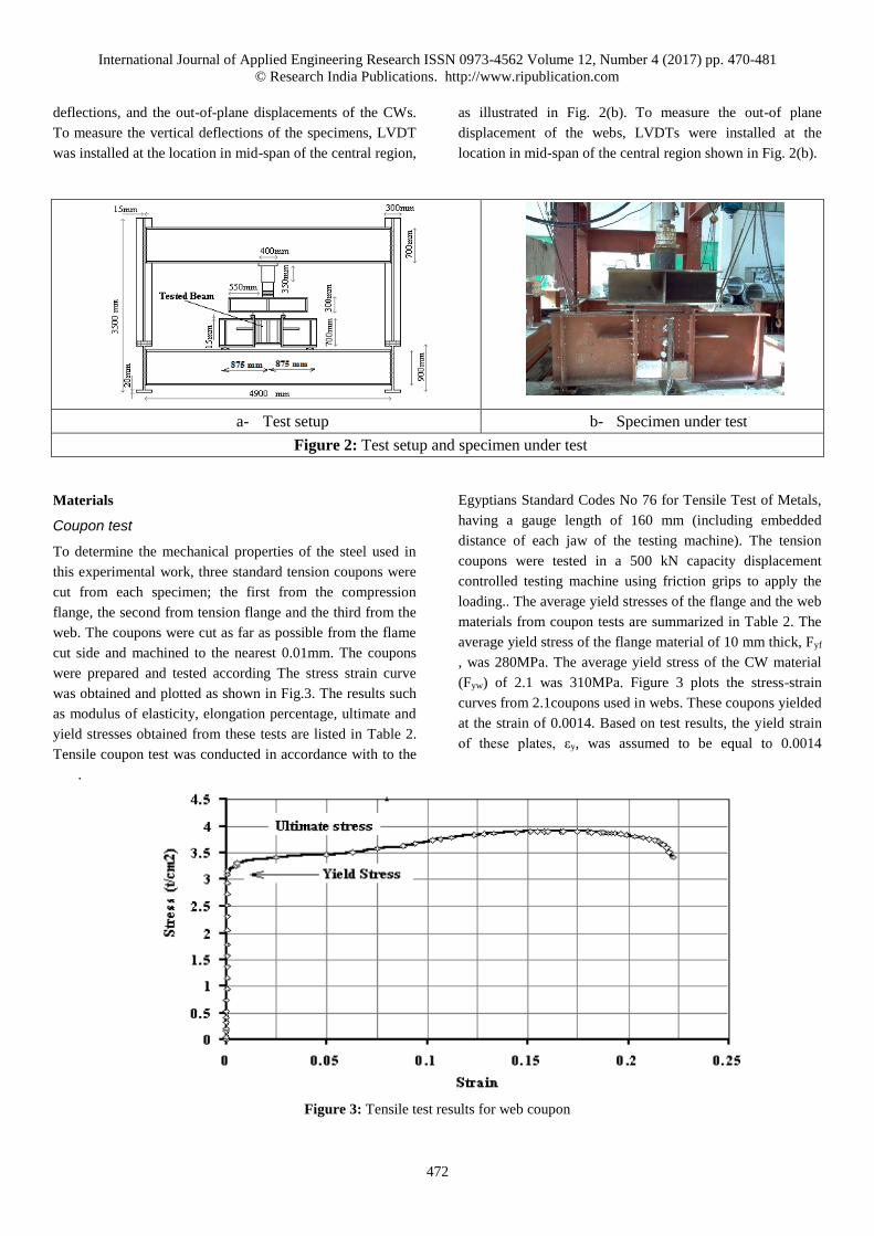
Test setup
The specimens tested under two lines loading, as shown in
Fig. 2. A concentrated load from the actuator was distributed
by the transfer beam. The capacity of the actuator was 1,000
kN. The central region with FW or CW, L (=0.4 m), was
subjected to constant bending moment. In both sides of the
central region, L1 (=0.75 m), the FW of 12 mm plates with
vertical and horizontal stiffeners was used to prevent shear
buckling. To prevent sudden lateral movement and torsion of
specimens, lateral supports were installed leaving 2 mm
spacing between the specimen and lateral supports. The
lateral supports were spaced 1.60 m apart away from the
transfer beam. The unbraced length of compressive flanges of
specimens was 1.60 m, by the locations of lateral supports.
To measure the strain of specimens, strain gauges were
attached to the webs, as shown in Fig. 2(b). Linear variable
displacement transformers (LVDT) were installed to measure
two kinds of displacements of specimens; the vertical
International Journal of Applied Engineering Research ISSN 0973-4562 Volume 12, Number 4 (2017) pp. 470-481
© Research India Publications. http://www.ripublication.com
472
deflections, and the out-of-plane displacements of the CWs.
To measure the vertical deflections of the specimens, LVDT
was installed at the location in mid-span of the central region,
as illustrated in Fig. 2(b). To measure the out-of plane
displacement of the webs, LVDTs were installed at the
location in mid-span of the central region shown in Fig. 2(b).
a- Test setup b- Specimen under test
Figure 2: Test setup and specimen under test
Materials
Coupon test
To determine the mechanical properties of the steel used in
this experimental work, three standard tension coupons were
cut from each specimen; the first from the compression
flange, the second from tension flange and the third from the
web. The coupons were cut as far as possible from the flame
cut side and machined to the nearest 0.01mm. The coupons
were prepared and tested according The stress strain curve
was obtained and plotted as shown in Fig.3. The results such
as modulus of elasticity, elongation percentage, ultimate and
yield stresses obtained from these tests are listed in Table 2.
Tensile coupon test was conducted in accordance with to the
Egyptians Standard Codes No 76 for Tensile Test of Metals,
having a gauge length of 160 mm (including embedded
distance of each jaw of the testing machine). The tension
coupons were tested in a 500 kN capacity displacement
controlled testing machine using friction grips to apply the
loading.. The average yield stresses of the flange and the web
materials from coupon tests are summarized in Table 2. The
average yield stress of the flange material of 10 mm thick, Fyf
, was 280MPa. The average yield stress of the CW material
(Fyw) of 2.1 was 310MPa. Figure 3 plots the stress-strain
curves from 2.1coupons used in webs. These coupons yielded
at the strain of 0.0014. Based on test results, the yield strain
of these plates, εy, was assumed to be equal to 0.0014
.
Figure 3: Tensile test results for web coupon

International Journal of Applied Engineering Research ISSN 0973-4562 Volume 12, Number 4 (2017) pp. 470-481
© Research India Publications. http://www.ripublication.com
473
Table 2: Modulus of Elasticity, Elongation percentage, Ultimate and Yield stresses
Coupon Type FY (N/mm2) Fu (N/mm2) E (N/mm2)
Compact Flange 300 375 200000 28
Non-compact Flange 320 390 213000 25
Web 310 390 205000 24
Failure mechanism
Specimens CWNCF101 and FWNCF201 after failure are
shown in figure 4; the vertical flange buckling into the
corrugated and FW beams can be noted in these specimens.
The flange and the CW buckled abruptly at the mid span of
the specimen, after yield of the top flange. As the load
increased, the buckling in the top flange increased, and then
the local buckling started to be deformed in case of FW only.
During the test, the strength of the bottom flange degraded,
and made the bottom flange yield first before the top flange
yielded.Until the bottom flange yielded, the specimen
behaved elastically, showing a linear relationship of load-
displacement curves. After the bottom flange began to yield,
the bending stiffness of the specimen gradually decreased.
After the whole section of the bottom flange yielded, and the
top flange began to yield, the bending stiffness of the
specimen considerably decreased. Unlike the steel beam with
the FW, the steel beam with CW behavior did not show any
local web buckling.
Specimens CWCF102 and FWCF202 after failure are shown
in figure 5; the top flange behave as compact flange during
all test time and without local buckling. The FW buckled
abruptly at the mid span of the specimen in the top middle
part. As the load increased, the buckling in the local web
buckling increased till failure. The behavior of steel beam
with CF and CW was controlled by the global web buckling.
a- Failure shape of steel beam with CW. b- Failure shape of steel beam with FW.
Figure 4: Steel beam specimens with non-compact flanges after testing
a) Failure shape of steel beam with CW b) Failure shape of steel beam with FW.
Figure 5: Steel beam specimens with compact flanges after testing

International Journal of Applied Engineering Research ISSN 0973-4562 Volume 12, Number 4 (2017) pp. 470-481
© Research India Publications. http://www.ripublication.com
474
Test results
Figure 6 shows mid span vertical displacement of test
specimens according to the applied vertical load obtained
experimentally. In table 3, the maximum load achieved by
each specimen with the crossponding maximum
displacement were listed. From these values it can be
conclude that the flexural strength of steel beams could be
decreased from 10% to 20% in case of using corrugated web
instead of flat web.
Table 3: Maximum load and displacement obtained experimentally
Spec. No. Max. load
(kN)
Max. displacement (mm) Load (%) from
reference Note
CWNCF101 100 12 80
CWCF102 345 13 87
FWNCF201 125 4.2 1 reference
FWCF202 400 10 1 reference
a. Beams with non-compact flanges and CW or
FW b. Beams with compact flanges and CW or FW
Figure 6: Load vs mid-span deflection - Experimental results of bare Steel beams
FINITE ELEMENT MODELING
The finite element elastic-plastic shell (Shell43) was
considered for steel section which built in ANSYS software
package. The element Shell43 is defined by four nodes
having six degrees of freedom at each node. The deformation
shapes are linear in both in-plane directions. The Shell43
element is capable of describing plasticity, large deflections
and large strains. The element allows for plasticity, creep,
stress stiffening, large deflections, and large strain
capabilities. In order to avoid numerical problems, the values
measured in the experimental tests for the material properties
of the steel components (webs and flanges) were used in the
finite element analyses. Displacement boundary conditions
were needed to constrain the model to get a unique solution.
To ensure that the model acts in the same way as the
experimental beam boundary conditions need to be applied at
the supports and loadings exist. The support was modeled in
such a way that hinged and roller were created. A single line
of nodes on the plate were given constraint in the Y, and X
directions, applied as constant values of zero in one side ,
where in the other side a single line of nodes on the plate
were given constraint in the X only. The force applied at ten
nodes each node on the plate is one tenth of the actual force
applied to eliminate the effect of located strain in each node.
Figure 1 illustrates the applied loads and boundary condition
for meshed steel beam with flat or CW. The finite element
mesh in the models was investigated by varying the size of
elements. In the flanges and web, the size of the elements
was 25 mm (length and width). The typical finite element
models of steel beams with corrugated or FW subjected to
vertical loads are shown in Fig. 7.
0
20
40
60
80
100
120
140
160
180
200
0 2 4 6 8 10 12 14 16 18 20
Non Compact Flange Beams
Ver
tica
lL
oad
kN
Vertical Displacement (mm)
Expermintal Flat Web results
Expermintal Corrugated Web results
International Journal of Applied Engineering Research ISSN 0973-4562 Volume 12, Number 4 (2017) pp. 470-481
© Research India Publications. http://www.ripublication.com
475
a. CW steel beam model b. FW steel beam model
Figure 7: Finite element model and boundary conditions
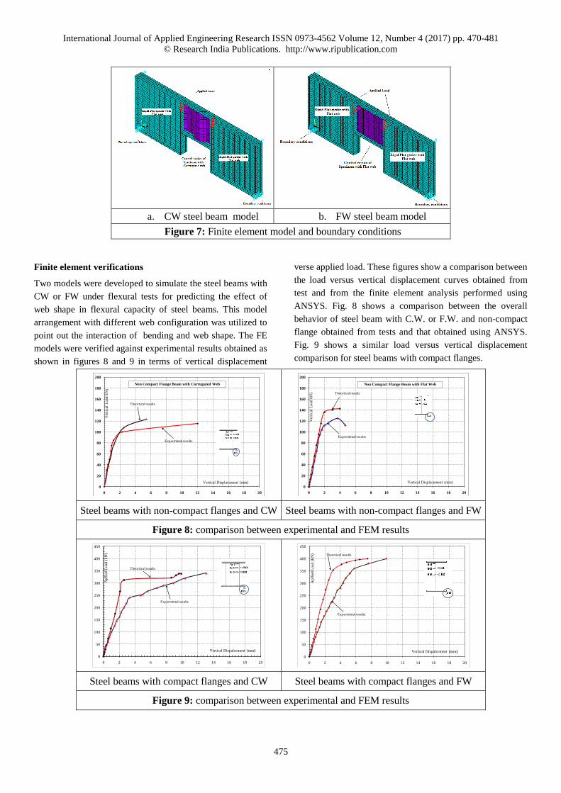
Finite element verifications
Two models were developed to simulate the steel beams with
CW or FW under flexural tests for predicting the effect of
web shape in flexural capacity of steel beams. This model
arrangement with different web configuration was utilized to
point out the interaction of bending and web shape. The FE
models were verified against experimental results obtained as
shown in figures 8 and 9 in terms of vertical displacement
verse applied load. These figures show a comparison between
the load versus vertical displacement curves obtained from
test and from the finite element analysis performed using
ANSYS. Fig. 8 shows a comparison between the overall
behavior of steel beam with C.W. or F.W. and non-compact
flange obtained from tests and that obtained using ANSYS.
Fig. 9 shows a similar load versus vertical displacement
comparison for steel beams with compact flanges.
Steel beams with non-compact flanges and CW Steel beams with non-compact flanges and FW
Figure 8: comparison between experimental and FEM results
Steel beams with compact flanges and CW Steel beams with compact flanges and FW
Figure 9: comparison between experimental and FEM results
0
20
40
60
80
100
120
140
160
180
200
0 2 4 6 8 10 12 14 16 18 20
Non Compact Flange Beam with Corrugated Web
Ver
tica
lL
oad
kN
)
Vertical Displacement (mm)
Expermintal results
Theortical results
0
20
40
60
80
100
120
140
160
180
200
0 2 4 6 8 10 12 14 16 18 20
Non Compact Flange Beam with Flat Web
Ver
tica
lL
oad
kN
)
Vertical Displacement (mm)
Expermintal results
Theortical results
0
50
100
150
200
250
300
350
400
450
0 2 4 6 8 10 12 14 16 18 20
Expermintal results
Theortical results
Ap
llie
d L
oad
(k
N)
Vertical Dispalcement (mm)
0
50
100
150
200
250
300
350
400
450
0 2 4 6 8 10 12 14 16 18 20
Expermintal results
Theortical results
Ap
llie
d L
oad
(k
N)
Vertical Dispalcement (mm)

International Journal of Applied Engineering Research ISSN 0973-4562 Volume 12, Number 4 (2017) pp. 470-481
© Research India Publications. http://www.ripublication.com
476
COMPOSITE CONCRETE/STEEL BEAMS WITH
CORRUGATED WEB
Specimens fabrication
The experimental program extended to study this effect when
using CW in composite concrete-steel beams. Two composite
concrete/steel beams with a corrugated web were fabricated
to study the effect of corrugated web on the beam flexural
capacity. The concrete slabs and the steel beams were
directly connected by shear connectors. Each of the beams
was 3100 mm long and simply supported on a span of 3000
mm. The concrete slabs of the composite beams were 900mm
long and 500mm wide. Each beam was divided into three
lengths; the middle one-third of the span (L=0.9 m) was
subjected to a constant moment, wherein both sides of the
middle one-third, bare stiffened steel beam were used to
prevent shear or moment buckling. The bolted connection
between the middle one-third and other parts was designed to
ensure failure at a mid-span without slip or bending in the
bolts. Figure 10 illustrates the details of fabricated composite
beams B1 and B2,which comprised top and bottom steel
flanges of 150mm in width and 10mm in thickness,
corrugated webs of 130mm in height and 2mm in thickness
as well as a top concrete slab. The reinforced concrete slab
was 80mm in depth. Meanwhile, the shear connectors had
angles measuring 40 × 40 × 4mm with a length of 150mm.
The angles were continuously welded to the top steel flange
and spaced at 200mm. The concrete slab contained a welded
mesh of reinforcement at mid-depth. The mesh reinforcement
comprised 10mm diameter high-tensile steel bars that were
longitudinally and transversally spaced by 150 mm and 178
mm, respectively. The stiffened and corrugated parts were
connected using 10mm thick plates and six M16 grade 10.2
bolts arranged in two columns and three rows. Central
distances of 100mm between the columns and 75mm
between the rows were used. A seat angle, measuring 100 ×
100 × 10mm, was welded at one leg to the bottom steel
flange of the tested part and connected with transversal
stiffeners by bolts from each end to avoid any failure in the
weld between the bottom steel flange and the transversal
stiffeners at both ends of the tested part. The component
plates and the webs were also accurately machined. The webs
in the tested parts were efficiently corrugated to obtain the
desired corrugation profiles. Meanwhile, the webs in all
beams were continuously welded to the flanges and vertical
stiffeners. Beam testing was conducted using a 5000kN-
capacity testing machine in the steel construction laboratory
of the faculty of engineering at Assiut university; Egypt. The
test beams were placed over the support at their ends, which
is in line with the end-bearing stiffeners to avoid the local
flange and web failure, as shown in Fig. 10. One end of the
beams was supported on a roller, and the other on a hinge, to
simulate the simply supported condition. The mechanical
properties of the flange and the web were the average of the
three specimens of the flange and web steel. Table 4 shows
the obtained mechanical properties (e.g., modulus of
elasticity, elongation percentage, ultimate and yield stresses)
for the six tension coupons and average results, respectively.
Figure 11 shows load versus vertical displacement curves
obtained from tests. Table 5 shows the maximum load and
moment achieved by the composite concrete steel beams with
corrugated web experimentally.
Table 4: Modulus of Elasticity, Elongation percentage,
Ultimate and Yield stresses
Coupon
Type
FY
(N/mm2)
Fu
(N/mm2)
E
(N/mm2)
CF 300 375 200000 28
NCF 320 390 213000 25
Web 310 390 205000 24
Table 5: Test results of composite concrete-steel beams
Mode of
failure
MU
(KN.m)
Pu /
pcr
pu
(kN)
kN
pcr
(kN)
kN
fcu
(N/mm2)
N /mm2
beam
No
Flex.
Comp.
(ductile)
89.25 2.12 170 62 27.5 B1
Flex.
Comp.
(ductile)
89.25 2.83 170 60 27.5 B2

International Journal of Applied Engineering Research ISSN 0973-4562 Volume 12, Number 4 (2017) pp. 470-481
© Research India Publications. http://www.ripublication.com
477
a. Cross-section elevation
b. Section A-A – Cross-section plan
c. Section B-B d. Section C-C
Figure 10: Details of test specimens B1 and B2 (all dimensions in mm)
Figure 11: Load–mid-span deflection curve for B1 and B2
Limit state design process
The limit state design is the latest design criteria and
procedures given in AS 4100, AS 2327.1, Eurocode 4, AISC-
LRFD specifications, and Australian Standards AS/NZS
1170. The limit state design philosophy has been adopted in
the current codes of practice as the basic design method for
the design of steel and composite structures as it is believed
that this method is capable of yielding safer and more
economical design solutions. This limit state may be caused
by the failure of one or more structural members, the
1050
50
stiffened part
1050 900
stiffened part
10thk. Bearing stiffener
10thk. transverse stiffener10thk. transverse stiffener
10thk. horizontal stiffener
on both sides of web 50
6Y10@178mm L 40X40X4mm L=150mm
shear stud@225mm
10thk. horizontal stiffener
on both sides of web
on both sides of web
on both sides of web
on both sides of webA A
C
C
B
B
5Y10@150mm10thk. Bearing stiffener
on both sides of web
mmmmmmmm
mm
3000
200 100 200 100 200 5050 50501050 1050
10
0
10thk. Bearing stiffener
on both sides of web
10thk. horizontal stiffener
on both sides of web
10thk. transverse stiffener
on both sides of web
10thk. horizontal stiffener
on both sides of web
10thk. transverse stiffener
on both sides of web
10thk. Bearing stiffener
on both sides of web
Sectio A-A
mm
mm
mm
mm
2
10
15
0
150
104
0 80
500 6Y10@178mm
5Y10@150mm
Section B-B
23
0
150
28
10
25
0
28
19
4
150
10thk. Bearing stiffener
on both sides of web
Section C-C
0
20
40
60
80
100
120
140
160
180
200
0 5 10 15 20 25 30 35
B1
B2
Ap
pli
ed
vert
ical L
oad
(kN
)
Mid-span Deflection (mm)
P/2 P/2

International Journal of Applied Engineering Research ISSN 0973-4562 Volume 12, Number 4 (2017) pp. 470-481
© Research India Publications. http://www.ripublication.com
478
instability of structural members or the whole structure, or
excessive deformations of the structure. In the limit state
design, the performance of a structure is evaluated by
comparison of design action effects with a number of limiting
conditions of usefulness.
Figure 12: Plastic stress distribution in composite section with 0 ≤ β ≤ 1.
Using the plastic stress distribution in composite section
shown in figure 12 the design equations process will be
performed as follow:
The composite beam is designed with (degree of shear
connection) β = 0.60 at the mid-span section as defined in
clause 1.4.3 of AS 2327.1 (β =Fcp
Fcc):
Fccis the compressive forces in the concrete slab with
complete shear connection
Fcpis the compressive forces in the concrete slab with
partial shear connection
The tensile capacity of the steel section is computed as:
Fst = [(bf1 ∗ tf1 + bf2 ∗ tf2) ∗ fyf + dw ∗ tw ∗ fyw]
The compressive forces in the concrete slab with partial
shear connection
Fst = Fcc
Fcp = β ∗ Fcc
The compressive capacity of the concrete slab is computed
as:
Fc1 = 0.85 ∗ fc′ ∗ bcf ∗ (Dc − hr) + As bar ∗ fy bar
Since Fcp<Fc1, the first plastic natural axis (PNA) lies in the
concrete cover slab.
The depth of the first PNA in the concrete slab is calculated
as:
dn1 =Fcp
0.85 ∗ fc′ ∗ bcf
The compressive force in the steel section is computed as:
Fsc = Fst − Fcp
The slenderness of the top steel flange in compression is:
λef =(bf − tw) ∗ 0.50
tf
∗ √fyf
250
Hence, the top flange of the steel section is compact; the
capacity of the steel top flange is:
2 ∗ Ff1 = 2 ∗ bf1 ∗ tf1 ∗ fyf
In this case 𝐹𝑠𝑐< 2 ∗ 𝐹𝑓1, the second natural axis lies in the
top flange of the steel section.
The depth of the second neutral axis is computed as:
dn2 =Fsc
bf1 ∗ (2 ∗ fyf)
The distance from the centroid of Fcp to top face of the steel
section is
dc = Dc −dn1
2
The distance from the centroid of Fst to the top face of the
steel section is given as :
dst =Ds
2
The distance from the centroid of Fsc to the top fiber of the
steel section is:
dsc =dn2
2
The nominal moment capacity is calculated as
Mb = Fcp ∗ (dc + dsc) + Fst ∗ (dst − dsc)
The result obtained from the above mentioned design
process was the nominal designed moment capacity which
found to be equal 84.3 kN.m. This value represents 95%
from the maximum moment that the specimens resisted

International Journal of Applied Engineering Research ISSN 0973-4562 Volume 12, Number 4 (2017) pp. 470-481
© Research India Publications. http://www.ripublication.com
479
experimentally. Details of the design process and the final
result shown in appendix A of this paper.
CONCLUSIONS
To study the effect of corrugated web on flexural capacity of
steel beams, a full scale test was conducted with
conventional steel I beams and compared with steel beams
with corrugated web. Experimental work has revealed the
range where the flexural capacity decreased. The study was
extended to compare the nominal moment capacity that can
be obtained theoretically from limit state design process and
experimentally for composite concrete steel beams with
corrugated web. Study results concluded the following:
1- The flexural capacity of steel beam with corrugated
web is less than the conventional steel I beam in a
range between 10 to 20%.
2- Flexural behavior of steel beam with flat web
shows local flange buckling followed by web local
buckling, unlike the steel beam with corrugated
web which shows earlier flange local buckling only.
3- The flexural capacity of composite concrete-steel
beam could be decreased by the same percentages
mentioned above in the case of using corrugated
web instead of flat web.
4- The finite element model can simulate the behavior
of bare steel beams especially in the elastic stage to
an acceptable degree of accuracy
REFRENCES
[1] Abbas, H.H., (2003); Analysis and Design of CW
Plate Girder for Bridges Using High Performance
Steel, Ph.D. Dissertation Lehigh University.
[2] Abbas, H. H., Sause, R., and Driver, R. G. (2006).
“Behavior of CW I-girders under in-plane loads.”
Journal of Engineering Mechanics, ASCE, 132(8),
pp.806-814.
[3] Aschinger, R. and Lindner, J. (1997). “Zu
Besonderheitenbei Trapezsteg Trägern.” Stahlbau,
66(3), pp. 136-142 (in German).
[4] Chan, C. L., Khalid, Y. A., Sahar, B. B., and
Hamouda, A.M. S. (2002). “Finite element analysis
of corrugated web beams under bending.” Journal
of Constructional SteelResearch, 58(11), pp. 1391-
1406.
[5] Elgaaly, M., Seshadri, A., and Hamilton, R. W.
(1997).“Bending strength of steel beams with
CWs.” Journal of Structural Engineering, ASCE,
123(6), pp.772-782.
[6] Huang, L., Hikosaka, H., and Komine, K.
(2004).“Simulation of accordion effect in
corrugated steel web with concrete flanges.”
Computers and Structures, 82, pp.2061-2069.
[7] Johnson, R. P. and Cafolla, J. (1997). “Local flange
bucklingin plate girders with corrugated steel
webs.” Proc.Institution of Civil Engineers-
Structures and Buildings,122(2), pp. 148-156.
[8] Khalid, Y. A., Chan, C. L., Sahari, B. B., and
Hamouda, A.M. S. (2004). “Bending behaviour of
corrugated web beams.” Journal of Materials
Processing Technology,150(3), pp. 242-254.
[9] Leiva-Aravena, L. (1987). Trapezoidally Corrug-
ated Panels: Buckling Behaviour under Axial
Compressionand Shear. Publication S: 87(1),
Division of Steel andTimber Structures, Chalmers
University of Technology,Gothenburg, Sweden.
[10] Lindner, J. (1992). “Zur Bemessung von
Trapezsteg Trägern.” Stahlbau, 61(10), pp. 311-318
(in German).
[11] Metwally, A. E. and Loov, R. E. (2003).
“Corrugated steel webs for prestressed concrete
girders.” Materials and Structures, 36(2), pp. 127-
134.
[12] Oh, J. Y., Lee, D. H., and Kim, K. S. (2012).
“Accordion effect of prestressed steel beams with
CWs.” Thin-Walled Structures, 57, pp. 49-61.
[13] Pasternak and Kubieniec, (2010), "Plate girders
with corrugated webs" Journal of Civil Engineering
and Management, 16(2), pp. 166-171
[14] Protte, W. (1993). “Zur Gurtbeulungeines
Trägernmit Profiliertem Stegblech.” Stahlbau,
62(11), pp. 327-332 (in German).
[15] Sayed-Ahmed, E. Y. (2007). “Design aspects of
steel I girders with corrugated steel webs.”
Electronic Journal of Structural Engineering, 7, pp.
27-40.
[16] Watanabe, K. and Kubo, M. (2006). “In-plane
bending capacity of steel girders with corrugated
web plates.” Journal of Japan Society of Civil
Engineers, 62(2), pp. 323-336 (in Japanese).

International Journal of Applied Engineering Research ISSN 0973-4562 Volume 12, Number 4 (2017) pp. 470-481
© Research India Publications. http://www.ripublication.com
480
Nomenclature
b : The length of the horizontal panel
bf : Flange width
c : Distance between flange plastic hinges
d : projected length of the inclined panel
𝑑𝑐 : The distance from the centroid of Fcp to top face of the steel section
𝑑𝑠𝑡 : The distance from the centroid of Fst to the top face of the steel section
𝑑𝑠𝑐 : The distance from the centroid of Fsc to the top fiber of the steel section
E: : Modulus of elasticity
𝐹𝑓1 : Capacity of the steel top flange
𝐹𝑐𝑐 : is the compressive forces in the concrete slab with complete shear connection
𝐹𝑐𝑝 : is the compressive forces in the concrete slab with partial shear connection
𝐹𝑠𝑐 : The compressive force in the steel section
fcu : Concrete compressive strength
fyf : Flange yield stress
fyw : Web yield stress
hr : The corrugation depth
𝑀𝑏 : The nominal moment capacity
𝑀𝑑 : The design nominal moment capacity
Pu : Ultimate load achieved experimentally.
tw : Web thickness
tf : Flange thickness
θ : The corrugation angle
β : Degree of shear connection
𝜆𝑒𝑓 : The slenderness of the top steel flange in compression
Appendix A
The composite beam is designed with (degree of shear connection) β = 0.60 at the mid-span section as defined in clause 1.4.3 of
AS 2327.1 (𝛽 =𝐹𝑐𝑝
𝐹𝑐𝑐):
𝐹𝑐𝑐is the compressive forces in the concrete slab with complete shear connection
𝐹𝑐𝑝is the compressive forces in the concrete slab with partial shear connection
The tensile capacity of the steel section is computed as:
𝐹𝑠𝑡 = [(𝑏𝑓1 ∗ 𝑡𝑓1 + 𝑏𝑓2 ∗ 𝑡𝑓2) ∗ 𝑓𝑦𝑓 + 𝑑𝑤 ∗ 𝑡𝑤 ∗ 𝑓𝑦𝑤] ∗ 0.85
𝐹𝑠𝑡 = [(150 ∗ 10 + 150 ∗ 10) ∗ 310 + 130 ∗ 2 ∗ 310] ∗ 0.85 = 859010 𝑁
The compressive forces in the concrete slab with partial shear connection
𝐹𝑠𝑡 = 𝐹𝑐𝑐
𝐹𝑐𝑝 = 𝛽 ∗ 𝐹𝑐𝑐
𝐹𝑐𝑝 = 0.6 ∗ 859.01 = 515.406 kN
The compressive capacity of the concrete slab is computed as:
𝐹𝑐1 = 0.85 ∗ 𝑓𝑐′ ∗ 𝑏𝑐𝑓 ∗ (𝐷𝑐 − ℎ𝑟) + 𝐴𝑠 𝑏𝑎𝑟 ∗ 𝑓𝑦 𝑏𝑎𝑟
𝐹𝑐1 = 0.85 ∗ 27.5 ∗ 500 ∗ (80) + 5 ∗ 78.57 ∗ 360 = 1076429 𝑁 = 1076.43𝑘𝑁
Since 𝐹𝑐𝑝<𝐹𝑐1, the first plastic natural axis (PNA) lies in the concrete cover slab.
The depth of the first PNA in the concrete slab is calculated as:

International Journal of Applied Engineering Research ISSN 0973-4562 Volume 12, Number 4 (2017) pp. 470-481
© Research India Publications. http://www.ripublication.com
481
𝑑𝑛1 =𝐹𝑐𝑝
0.85 ∗ 𝑓𝑐′ ∗ 𝑏𝑐𝑓
𝑑𝑛1 =515.406 ∗ 1000
0.85 ∗ 27.5 ∗ 500 = 44.1 𝑚𝑚
The compressive force in the steel section is computed as:
𝐹𝑠𝑐 = 𝐹𝑠𝑡 − 𝐹𝑐𝑝
𝐹𝑠𝑐 = 859.01 − 515.406 = 343.6 𝑘𝑁
The slenderness of the top steel flange in compression is:
𝜆𝑒𝑓 =(𝑏𝑓 − 𝑡𝑤) ∗ 0.50
𝑡𝑓
∗ √𝑓𝑦𝑓
250
𝜆𝑒𝑓 =(150 − 2) ∗ 0.50
10∗ √
310
250 = 8.2 < 9
Hence, the top flange of the steel section is compact; the capacity of the steel top flange is:
2 ∗ 𝐹𝑓1 = 2 ∗ 𝑏𝑓1 ∗ 𝑡𝑓1 ∗ 𝑓𝑦𝑓
2 ∗ 𝐹𝑓1 = 2 ∗ 150 ∗ 10 ∗ 310 = 930000𝑁 = 930 𝑘𝑁
If 𝐹𝑠𝑐< 2 ∗ 𝐹𝑓1, the second natural axis lies in the top flange of the steel section.
The depth of the second neutral axis is computed as:
𝑑𝑛2 =𝐹𝑠𝑐
𝑏𝑓1 ∗ (2 ∗ 𝑓𝑦𝑓)
𝑑𝑛2 =343.06 ∗ 1000
150 ∗ (2 ∗ 310) = 3.69 𝑚𝑚 < 𝑡𝑓
The distance from the centroid of Fcp to top face of the steel section is
𝑑𝑐 = 𝐷𝑐 −𝑑𝑛1
2
𝑑𝑐 = 80 −44.1
2 = 58 𝑚𝑚
The distance from the centroid of Fst to the top face of the steel section is given as :
𝑑𝑠𝑡 =𝐷𝑠
2
𝑑𝑠𝑡 =150
2 = 75 𝑚𝑚
The distance from the centroid of Fsc to the top fiber of the steel section is:
𝑑𝑠𝑐 =𝑑𝑛2
2
𝑑𝑠𝑐 =3.69
2 = 1.8 𝑚𝑚
The nominal moment capacity is calculated as
𝑀𝑏 = 𝐹𝑐𝑝 ∗ (𝑑𝑐 + 𝑑𝑠𝑐) + 𝐹𝑠𝑡 ∗ (𝑑𝑠𝑡 − 𝑑𝑠𝑐)
𝑀𝑏 = 515406 ∗ (58 + 1.8) + 859010 ∗ (75 − 1.8) = 93700000 = 93.7 𝑘𝑁. 𝑚
𝑀𝑑 = 𝜙 ∗ 𝑀𝑏 = 0.9 ∗ 93.7 = 84.3 𝑘𝑁. 𝑚