Embed Size (px)
Citation preview
ECE 477 Final ReportSpring 2005
Team Code Name: _____I, Robotic Waitress______________________ Team ID: __10__
Team Members (#1 is Team Leader):
#1: ___Jer-Wei Lam______________ Signature: ____________________ Date: 05/04/2005
#2: ___Kevin Muthuri____________ Signature: ____________________ Date: 05/04/2005
#3: ___Ming Sum Wong___________ Signature: ____________________ Date: 05/04/2005

ECE 477 Final Report Spring 2005
#4: ___Jacinto Chang_____________ Signature: ____________________ Date: 05/04/2005
REPORT EVALUATION
Component/Criterion Score Multiplier Points
Abstract 0 1 2 3 4 5 6 7 8 9 10 X 1
Project Overview and Block Diagram 0 1 2 3 4 5 6 7 8 9 10 X 2
Team Success Criteria/Fulfillment 0 1 2 3 4 5 6 7 8 9 10 X 2
Constraint Analysis/Component Selection 0 1 2 3 4 5 6 7 8 9 10 X 2
Patent Liability Analysis 0 1 2 3 4 5 6 7 8 9 10 X 2
Reliability and Safety Analysis 0 1 2 3 4 5 6 7 8 9 10 X 2
Ethical/Environmental Impact Analysis 0 1 2 3 4 5 6 7 8 9 10 X 2
Packaging Design Considerations 0 1 2 3 4 5 6 7 8 9 10 X 2
Schematic Design Considerations 0 1 2 3 4 5 6 7 8 9 10 X 2
PCB Layout Design Considerations 0 1 2 3 4 5 6 7 8 9 10 X 2
Software Design Considerations 0 1 2 3 4 5 6 7 8 9 10 X 2
Version 2 Changes 0 1 2 3 4 5 6 7 8 9 10 X 1
Summary and Conclusions 0 1 2 3 4 5 6 7 8 9 10 X 1
References 0 1 2 3 4 5 6 7 8 9 10 X 2
Appendix A: Individual Contributions 0 1 2 3 4 5 6 7 8 9 10 X 4
Appendix B: Packaging 0 1 2 3 4 5 6 7 8 9 10 X 2
Appendix C: Schematic 0 1 2 3 4 5 6 7 8 9 10 X 2
Appendix D: Top & Bottom Copper 0 1 2 3 4 5 6 7 8 9 10 X 2
Appendix E: Parts List Spreadsheet 0 1 2 3 4 5 6 7 8 9 10 X 2
Appendix F: Software Listing 0 1 2 3 4 5 6 7 8 9 10 X 2
Appendix G: User Manual 0 1 2 3 4 5 6 7 8 9 10 X 2
Appendix H: FMECA Worksheet 0 1 2 3 4 5 6 7 8 9 10 X 2
Technical Writing Style 0 1 2 3 4 5 6 7 8 9 10 X 5
CD of Website Image and Reports/Poster 0 1 2 3 4 5 6 7 8 9 10 X 2
TOTAL
-ii-
Comments:

ECE 477 Final Report Spring 2005
TABLE OF CONTENTS
Abstract 1 1.0 Project Overview and Block Diagram 2 2.0 Team Success Criteria and Fulfillment 4 3.0 Constraint Analysis and Component Selection 5 4.0 Patent Liability Analysis 10 5.0 Reliability and Safety Analysis 13 6.0 Ethical and Environmental Impact Analysis 18 7.0 Packaging Design Considerations 22 8.0 Schematic Design Considerations 25 9.0 PCB Layout Design Considerations 2810.0 Software Design Considerations 3011.0 Version 2 Changes 3412.0 Summary and Conclusions 3513.0 References 36Appendix A: Individual Contributions A-1Appendix B: Packaging B-1Appendix C: Schematic C-1Appendix D: PCB Layout Top and Bottom Copper D-1Appendix E: Parts List Spreadsheet E-1Appendix F: Software Listing F-1Appendix G: User Manual G-1Appendix H: FMECA Worksheet H-1
-iii-
ECE 477 Final Report Spring 2005
Abstract
The purpose of this project is to design an automated robotic waitress that is capable of traveling
through given set points in order to serve food to various tables in a restaurant. Proximity IR
sensors will be used to detect any objects blocking the robots’ path. Another IR sensor on the
tray will check if the tray has been emptied and is ready to go back to the control center. It will
communicate wirelessly through a Radio Frequency (RF) interface to a control center to acquire
an instruction denoting which table to travel to, signal alerts, and also send its current status. By
counting the number of rotations of the motor, a reasonable estimate of the robotic waitress’
position can be calculated. With this information, the control center has the ability to
circumnavigate obstacles in the waitress’ path using a software algorithm if needed. An intuitive
user interface will be provided on the control center computer. This software will allow the user
to check on the current status and position of the robot and also call the robotic waitress back to
the control center at any point in time. All calculations and navigation algorithms are done in the
microcontroller.
-1-

ECE 477 Final Report Spring 2005
1.0 Project Overview and Block Diagram
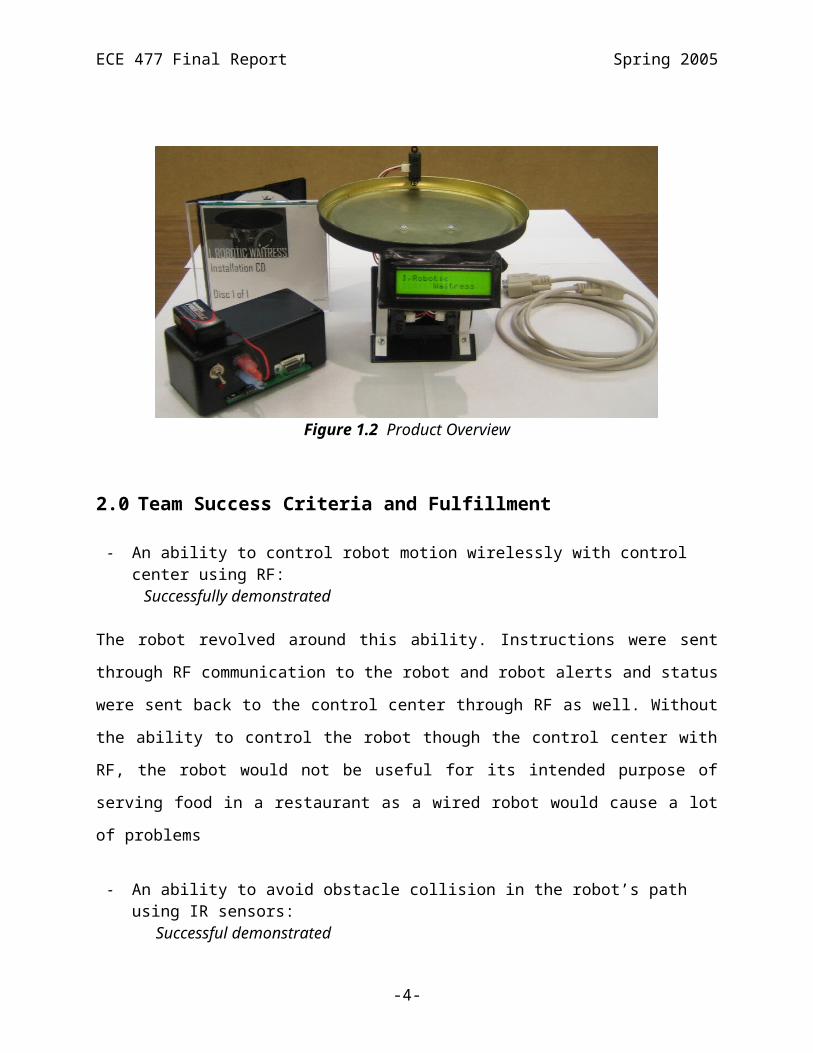
The “Robotic Waitress” delivers food to a designated table autonomously. It comprises of two
major components, the robot and the control center. The robot and the control center
communicate with each other using RF. The control center instructs the robot by sending it
packets of bytes to indicate the table where food is to be delivered. These packets are comprised
of a start byte, a data byte, and an end of package byte. Once the robot has received a valid
packet, it will deliver food to the designated table. It decodes the packet too see what table the
food is to be delivered to and then looks at the stored coordinates of the given table to calculate
its path. Once food has been delivered, the robot will return to its original departure point. The
system includes several external features to increase its dependability. An LCD on the robot
displays the current status of the robot, a buzzer is used as an alarm, an IR sensor is used as a
food detector, and two proximity IR sensors are used to detect obstacles along the path of the
robot. The robot is also capable of sending alerts back to the control center. Upon encountering
an obstacle, the robot tries to re-route, if it fails, it sends an alert back to the control center. It also
sends an alert back to the control center if the food has been removed before the robot reaches its
assigned table. The robot uses two servos that are powered by four AA batteries. The robots’
main board and the control centers’ RF system are powered by a 9V battery.
-2-

ECE 477 Final Report Spring 2005
Figure 1.1 Block Diagram
Figure 1.2 Product Overview
-3-

ECE 477 Final Report Spring 2005
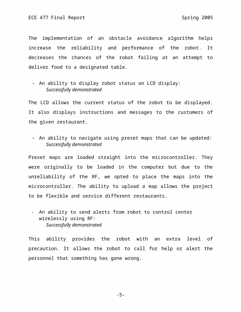
2.0 Team Success Criteria and Fulfillment
- An ability to control robot motion wirelessly with control center using RF: Successfully demonstrated
The robot revolved around this ability. Instructions were sent through RF communication to the
robot and robot alerts and status were sent back to the control center through RF as well. Without
the ability to control the robot though the control center with RF, the robot would not be useful
for its intended purpose of serving food in a restaurant as a wired robot would cause a lot of
problems
- An ability to avoid obstacle collision in the robot’s path using IR sensors: Successful demonstrated
The implementation of an obstacle avoidance algorithm helps increase the reliability and
performance of the robot. It decreases the chances of the robot failing at an attempt to deliver
food to a designated table.
- An ability to display robot status on LCD display: Successfully demonstrated
The LCD allows the current status of the robot to be displayed. It also displays instructions and
messages to the customers of the given restaurant.
- An ability to navigate using preset maps that can be updated: Successfully demonstrated
Preset maps are loaded straight into the microcontroller. They were originally to be loaded in the
computer but due to the unreliability of the RF, we opted to place the maps into the
microcontroller. The ability to upload a map allows the project to be flexible and service
different restaurants.
- An ability to send alerts from robot to control center wirelessly using RF: Successfully demonstrated
This ability provides the robot with an extra level of precaution. It allows the robot to call for
help or alert the personnel that something has gone wrong.
-4-

ECE 477 Final Report Spring 2005
3.0 Constraint Analysis and Component Selection
Computational Requirements
Computationally expensive tasks required for this project have been reduced by offloading
certain tasks from the microcontroller to the control center host computer. The exact position of
the robotic waitress is not needed by the robot itself, it is sufficient to record the number of times
the wheels have rotated since the last check point. The number of rotations is actually done by
counting the pulse width signal provided to the motors. Other simpler computational tasks were
left to the microcontroller but minimized in general.
Interface Requirements
The major interface to the microcontroller would be the servo motors [1]. These motors are
modified in such a way that only a pulse width module is needed to be supplied for them to run.
Using two motors, one for each wheel, requires the use of two PWM signals from the
microcontroller. As previously stated, keeping track of the distance traveled by the robot is of
major importance. To accomplish this task, a simple calculation can be made by observing the
sequence of pulses that the motor receives and the period of time the motor receives this
sequence of pulse. This attack to the problem simplifies calculations and avoids interfacing
directly with the motor for degrees rotated. A major setback of this method is its accuracy. It
assumes that the wheels are in contact with the ground at all times and therefore does not account
for slippage of the wheels.
The microcontroller must also interface with several infra-red (IR) sensors. Two IR sensors,
more specifically distance measuring sensors [2], will be needed in front of the robotic waitress
in order to detect obstacles in its path of travel. Two will be used instead of one because of the
limited detection angle of the chosen IR sensors. These sensors provide safer and higher
preventive measures for the robot. The chosen sensors work in an extremely simplistic manner:
if it detects an object closer than the chosen preset distance, a high signal is transmitted to the
microcontroller. Another IR sensor will also be used to detect if the tray on the waitress is empty;
-5-
ECE 477 Final Report Spring 2005
therefore, ready to go back to the control center for more instructions. However, this
implementation of the sensor on the tray only works if food is placed along the center line of the
tray as the angle of object detection of the sensor is minimal.
For wireless communication between the robotic waitress and the control center computer we
had initially chosen to use IR transmitters and receivers, but due to its small range of detection
and straight line of sight needed for reception of the signal, RF transmitters and receivers were
chosen. Due to varying restaurant sizes, reliable transmission for a distance of approximately 30
meters would be needed. Two separate sets of transmitters and receivers are to be used instead of
transceivers in order to minimize collision between inbound and outbound packets. The
frequency of the pair of transmitters and receivers were chosen to be of different harmonics, 418
MHz and 315 MHz, in order to minimize wave interference. Also, since a new communication
protocol will be implemented in our design the RF modules must then interface with the
microcontroller using UART connection.
Communication between the customers of a restaurant and the robotic waitress is absolutely
necessary. For this reason we decided to interface the microcontroller with a 16x2 LCD display
[3]. This LCD display will display robot status, destination point, and other messages. It will
need to interface 8 pins with the microcontroller, where 8 of those pins are needed to drive it.
This LCD display was chosen over other LCD displays that need 4 inputs to be driven because it
would be easier to drive the LCD display without the need to send in the data in packets.
A buzzer will be used as an alert sound. The buzzer is simple to interface and only needs one pin
from the microcontroller. It is activated whenever it finds an obstacle in its path. Such device
will be useful in for any type of alert needed. A buzzer was chosen over speakers because of its
simple input.
Power Supply Constraints
All components chosen are capable of running at 5 volts. The main concern with respect to
power is the use of servo motors. The heavier the robot is, the more power will be consumed. For
-6-
ECE 477 Final Report Spring 2005
this reason, we have decided to use a separate power supplies for the servo motors and the main
board. Four rechargeable batteries, providing 4.8 volts, will be used for the servo motors and a
stepped-down regulated 9 volt battery will be used for the main board. The main reason for the
split of power supplies is reliance. The batteries will definitely deplete quicker because of the
motors, and by having two separate power sources, we will be able to communicate with the
robot even when the robot is unable to move because of depleted batteries. To provide more cost
effective robotic waitress, we are to make it run on rechargeable batteries. The transmission
module at the control center will not come across the same problem. It will either be powered by
batteries or a 5VDC power source.
Packaging Constraints
Packaging is currently a big constraint. The initial purpose of our robotic waitress is to serve at
sushi restaurants due to its size. Later models will definitely be larger, but for this prototype the
size has been chosen to be small. The tray therefore may only contain the food for two tables at a
time. The size of the main board will be located under the tray and in the chassis of the robot.
This space is approximately 3 inches by 2 inches. However, if the design needs to be placed in a
bigger board, the layout of the PCB may be increased and finally be placed under the tray with
extensions coming from the chassis of the robot.
Weight is also a very important constraint. The amount of weight the robot is able to carry must
be limited. As weight increases more power is needed to drive the motors to move the robot. For
this reason we must keep the weight of the robotic waitress to its minimum, allowing more
weight to be placed on the tray instead. Inertia and momentum are also affected and increased as
weight increases. However, the robot will be traveling at a slower speed such that these two
factors will be of minimum effect.
Cost Constraints
A robotic waitress does not only increase efficiency in delivery of food but also uses less human
resources. This means that businesses using this robotic waitress will need fewer employees to
-7-

ECE 477 Final Report Spring 2005
serve as waiters and waitresses. Also, prototyping this product does cost over $100, but once it
goes into mass production, the production cost should drop to about $70. For these reasons, a
reasonable market price for such a serviceable robot would ideally be $199.
Component Selection Rationale
A very important factor that went into our component selection was simplicity, ease of use, and
low cost. When selecting the type of motors to be used in our design we initially looked at h-
bridge motors. But after some research we found there were servo motors which were much
simpler to operate as it only needed a pulse width modulated signal. Also, the fact that two
motors were needed, one for each wheel, lead us to choose the servo motors over the common h-
bridge motors. Other servo motors were researched as well, but finding an optimal size servo
motor for our pre-designed robot chassis was hard to find. For this reason, and also because no
encoder was needed, we chose the servo motor that were sold along with the chassis of the robot.
A great variety of RF modules were found. Our goal was to find cost efficient pair of RF
modules that would work within the range of 30 meters. The first set of RF modules were
manufactured by Linx Techonlogies and operated at three different frequencies 315Mhz,
418Mhz, and 433Mhz. These are capable of transmitting 5000 bps and also support serial
interfaces. The other set of RF modules where manufactured by Abacom Technologies. Their
modules worked on 418Mhz, 433.92Mhz, 868.35Mhz and 916.5Mhz but their transmission rate
was of 2400bps. Both of these manufacturers provided great product detail and seemed to suit
our project specifications. However, the modules provided by Abacom Technologies[4] were
more expensive and lead us to choose the Linx RF modules [5].
A microcontroller was needed to interface with all of the above peripherals and more. Some of
the requirements that our microcontroller must have is UART interface to communicate with the
RF modules, two PWM’s, two external interrupts, and a lot of general I/O pins. We initially
considered obtaining a PIC microcontroller as it was able to provide us with the features and
interfaces we needed. However, the small number of instruction set architecture provided made
us doubt on the PIC microcontroller. We were hoping to have more ISA instructions in order to
-8-

ECE 477 Final Report Spring 2005
ease its programming. After some research it was found that the ATMEL AVR series of
microcontrollers had similar features and interfaces but with a superior development
environment and instruction set architecture. The Atmel AVR series also offered a greater
number of working registers when compared to the PICmicros. We looked at a few models of
Atmel AVR’s and finally chose the ATmega32 [6] because it provided the entire interface
needed, plenty of IO pins, and a large EEPROM and FLASH memory.
-9-

ECE 477 Final Report Spring 2005
4.0 Patent Liability Analysis
The database on the US Patent and Trademark Office website[1] was searched with the keyword
“robotic waitress”, “robot waitress” and “food robot” to see if there is any similar project filed
for patents, however nothing was found. Then a searched was made to see if any patent may be
infringed by individual portions of our project and found a few possible infringements.
Patent #6,597,143 Mobile robot system using RF module
This patent is filed on June 12, 2001 and is assigned to Samsung Electronics [2]. In this patent, a
mobile robot system includes a RF module that is under the control of a controlling computer is
described. The mobile robot system includes a running device for moving the mobile robot about
a room, an obstacle detecting device for detecting the presence of an obstacle in the mobile
robot's path, a location recognizing device and transceivers for transmitting and receiving a
signal to control the various devices.
Patent #6,667,592 Mapped robot system
This patent is filed on August 13, 2001 and is assigned to Intellibot LLC [3]. This patent
describes a method of utilizing a robot system is provided comprising the steps of commanding
the robot system to perform a function in an area. The method further includes accessing by the
robot system a stored map of the area layout, the stored map having at least one function task
associated with the at least one area segment.
Patent #6,543,983 Robotic pick up and deliver system
This patent is filed on February 10, 2000 and is assigned to University of Virginia Patent
Foundation [4]. In this patent, a pick up and delivery system for use with mobile robots which
have a body with a horizontal upper surface is described. The system further uses multiple
stations, each of which contain at least one pallet retaining surface to contain at least two pallets.
The mobile robot picks up a pallet from a first station, and delivers the pallet to a second station.
Patent #6,760,647 Socially interactive autonomous robot
-10-
ECE 477 Final Report Spring 2005
This patent is filed on January 21, 2003 and is assigned to Axxon Robotics, LLC [5]. In this
patent, a robot that is capable of substantially autonomous movement includes a processing
device, a memory, and a mobility structure is described. The processor directs the robot to move
with any predetermined safe area having a boundary and a reference point. The robot also
exhibits features of social interactivity by accepting an input from a human.
Analysis of Patent LiabilityLiteral Infringement
No literal infringement exists.
Infringement under Doctrine of Equivalents
Patent #6,597,143 Mobile robot system using RF module
The description of this patent is very similar to Robotic Waitress. Both systems include a control
center that can communicate with the robot via an RF module, mobile robot that can move and
an obstacle detecting device for detecting the presence of an obstacle in the robot's path.
Although Robotic Waitress determines its position by counting the number of rotations of the
motor instead of a location recognizing device described by this patent, we are substantially
performing the same function.
Patent #6,667,592 Mapped robot system
Robotic Waitress performs similar function as the description of this patent. Both systems
contain information of the destinations so the robot can navigate to the designated area. However
the form we store the information is different. As described in this patent, information is stored
as an area layout map format and the stored map is edited by the robot system upon the detection
of an obstacle in the function path. Robotic Waitress just stores a list of instructions to get to the
destinations and nothing will be updated upon detection of an obstacle. Further more, no specific
function task is associated with each designated area in our design. Hence, infringement under
the doctrine of equivalents does not exist for this patent.
Patent #6,543,983 Robotic pick up and deliver system
-11-

ECE 477 Final Report Spring 2005
This patent describes a pick up and delivery system for use with mobile robots having a body
with a horizontal upper surface, which is similar to the tray mounted on Robotic Waitress.
However, this patent also describes the use of multiple stations which contain at least one pallet
retaining surface to contain at least two pallets. In our design, we do not have any physical
station. Neither pallet nor retaining surface is used. Since we do not perform exactly the same
function, we do not infringe this patent under doctrine of equivalents.
Patent #6,760,647 Socially interactive autonomous robot
Our design is similar to this patent in the way that both systems include a processing device, a
memory, and a mobility structure. However, this patent describes a method such that the sensors
are used to measure human condition. In Robotic Waitress, sensors are used to monitor the status
of the robot and to detect obstacles. Hence we do not infringe this patent under the doctrine of
equivalents as we perform substantially different functions.
Action RecommendedSince our design, Robotic Waitress may infringe the patent #6,597,143 (Mobile robot system
using RF module), we may have to obtain a license or pay royalty to Samsung Electronics [2] if
we decide to market the product. Another suggestion is that we can change our design to use
other transmission methods like WiFi or GPS to navigate our robot.
-12-

ECE 477 Final Report Spring 2005
5.0 Reliability and Safety Analysis Five components that were thought to have the greatest probability of failing based on
complexity of operation, heat dissipation and power consumption were chosen for reliability
analysis. These components were the LM7805C (Voltage Regulator), the RXM-418-LC-S-ND
(RF receiver module), the TXM-315-LC-ND (RF transmitter module), the ATMEGA32-16PI-
ND (Atmel micro controller), and the continuous-rotation ball bearing servo motors (GWS S03N
2BB Standard-torque Ball-bearing Servo motors modified for continuous rotation). These
components were chosen because they tended to generate the most heat and they were critical to
the correct working of the design. Constant failure rates of these devices were calculated based
on 106 hours of operation (λ P). The LM7805C failure rate was determined from Eq.1 below
whereby λP is the number of failures per 106 hours of operation. [1] The equation for MTTF
(mean time to failure) is listed as in Eq.2 below.
λP = (C1πT + C2πE) πQπL (Eq.1)
1/ λP = MTTF (Eq.2)
The parameter values in Eq.1 depend on various environmental constants as well as how the
LM7805C is designed. C1 is the die complexity, πT is the temperature coefficient, C2 is a constant
based on the number of pins, πE is an environmental constant, πQ is the manufacturing quality
factor and πL is the learning factor which is based on how long the component has been in
production. It was assumed that environmental temperatures would range between 25°C and
45°C. Table 5.1 lists the parameter values for the LM7805C; the assumptions made and
calculated failure/106 hours and MTTF.
Parameter Assumptions
C1 = 0.01 Linear device, number of transistors < 100 [1] , [2]
πT = 58 TJ < 125 °C [1], [2]
C2 = 0.00092 Hermetic, TO – 220, 3 pins [1], [2]
πE = 4 Ground mobile environment [1]
πQ = 1 High quality commercial device [1]
-13-

ECE 477 Final Report Spring 2005
πL = 1.0 ICs more than two years in production [1], [3]
λP = 0.58368
MTTF = 1.713 × 10⁶ hrs
Table 5.1: Component Reliability Analysis for LM7805C
The RXM-418-LC-S-ND and TXM-315-LC-ND were treated as surface acoustic devices [4]
which utilize Eq.3 to determine the failures per 106 hours.
λP = 2.1πQπ E (Eq.3) [1]
Table 5.2 lists the parameter values for both the RXM-418-LC-S-ND and TXM-315-LC-ND; the
assumptions made and calculated failure/106 hours and MTTF.
Parameter Assumptions
πQ = 1 No screen levels beyond best commercial
practice [1]
πE = 4 Ground mobile environment [1]
λP = 8.4
MTTF = 0.119 × 10⁶ hrs
Table 5.2: Component Reliability Analysis for RXM-418-LC-S-ND and TXM-315-LC-ND
For the ATMEGA32-16PI-ND, Eq.1 and Eq.2 were used to determine the failures/106 hours and
MTTF respectively. Table 5.3 lists the parameter values for the ATMEGA32-16PI-ND; the
assumptions made and calculated failure/106 hours and MTTF.
Parameter Assumptions
C1 = 0.14 MOS, 8 bits [1], [3]
πT = 1.5 TJ < 100 °C [1], [3]
C2 = 0.015 Hermetic, DIP, 40 pins [1], [3]
πE = 4 Ground mobile environment [1]
πQ = 1 High quality commercial device [1]
-14-

ECE 477 Final Report Spring 2005
πL = 1.0 ICs > two years in production [1], [3]
λP = 0.27
MTTF = 3.704 × 10⁶ hrs
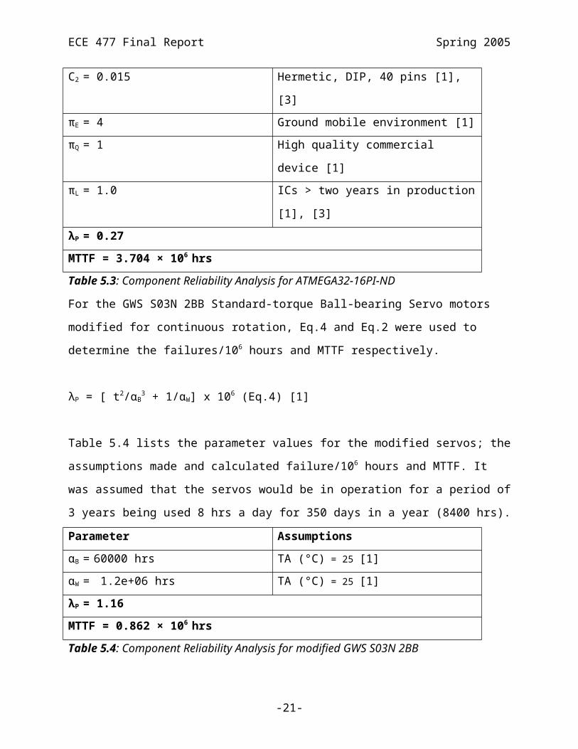
Table 5.3: Component Reliability Analysis for ATMEGA32-16PI-ND
For the GWS S03N 2BB Standard-torque Ball-bearing Servo motors modified for continuous
rotation, Eq.4 and Eq.2 were used to determine the failures/106 hours and MTTF respectively.
λP = [ t2/αB3 + 1/αW] x 106 (Eq.4) [1]
Table 5.4 lists the parameter values for the modified servos; the assumptions made and
calculated failure/106 hours and MTTF. It was assumed that the servos would be in operation for
a period of 3 years being used 8 hrs a day for 350 days in a year (8400 hrs).
Parameter Assumptions
αB = 60000 hrs TA (°C) = 25 [1]
αW = 1.2e+06 hrs TA (°C) = 25 [1]
λP = 1.16
MTTF = 0.862 × 10⁶ hrs
Table 5.4: Component Reliability Analysis for modified GWS S03N 2BB
From the calculations above, it was noted that of the five components chosen, the one most likely
to fail would be the RXM-418-LC-S-ND or the TXM-315-LC-ND RF modules. The MTTF for
the RF modules was determined to be 119,000 hrs, which is much less than 3,704,000 hrs for the
ATMEGA32-16PI-ND and 1, 713,000 hrs for the LM7805C, but only slightly less than 862,000
hrs for the LM7805C. If some of these devices failed in a particular manner, there may be a
potential for personal injury to users, consequently, such failures were considered to be of high
criticality. In addition, if any of the above devices malfunctioned, the overall design would not
work as intended. In reality, however, these components would have much lower failure rates
than determined because the junction temperatures would be much lower than the conservative
junction temperatures used in the calculations.
-15-
ECE 477 Final Report Spring 2005
Failure Mode, Effects and Criticality Analysis (FMECA)
Criticality was determined to be of two levels: low and high. A low criticality failure was defined
to be one that could be easily remedied by replacing a component or making slight modification
to the component such as recalibration of servo motors. On the other hand, a high criticality
failure was defined to be one that had a potential to cause personal injury to users or one that
would cause extensive damage to the design and may not be repairable. A failure rate of 10-6 was
determined acceptable for low criticality failures and 10-9 for medium criticality failures.
The schematic was divided into four functional blocks:
1. (A) Power Circuits.
2. (B) Microcontroller block
3. (C) Sensor block.
4. (D) RF Modules.
-16-

ECE 477 Final Report Spring 2005
Figure 5.1: Schematic divided up into Functional Blocks
-17-

ECE 477 Final Report Spring 2005
6.0 Ethical and Environmental Impact Analysis
Ethical Impact Analysis
As we now have a proof-of-concept, it is vital that we analyze the ethical impact of bringing our
design to market. Some of the key areas of concern are the durability, safety performance as well
as the social ethical impact of our robot design.
Durability – In order for our product to work in a real restaurant environment, our product
must be durable. The wheels, chassis and tray must be able to handle the every day beating in a
restaurant environment. In order to attain maximum durability, our design must be put through
a series of rigorous testing from which we can simulate real world handling of the robot. Weak
points must be reinforced and potentially the chassis may have to be redesigned if it was to be
made a solid platform. Limitations of the design should be made clear to the user through the
use of warning labels that are stuck onto the robot when the product is shipped. The user
manual should contain specifications of the design and limitations of the amount of weight,
type of product that it will be carrying.
Safety – Going in tandem with durability, our robot must be put through stringent testing for
operational safety. Due to the nature of the product where liquid may come in contact with the
physical robot, steps must be taken to ensure that all critical components be water tight to
prevent internal damage that may eventually lead to other safety issues. It is also very
important to notify customers in a restaurant that a robot is being operated in the vicinity.
People have to be aware that a machine is doing the task of servicing them and a watchful eye
must be kept when the robot is in operation. We strongly suggest the use of warning labels in
the restaurants to keep customers and employees alert all the time. A robot should be inspected
immediately if any signs of malfunctioning arise.
Rechargeable batteries must be handled with care when being charged. Overcharging of Ni-
MH, Ni-Cd, Li-ion, Li-polymer may cause fire or even explode [1]. Circuitry to prevent
overcharging and smart charging of these batteries should be adopted in our design to make it
-18-

ECE 477 Final Report Spring 2005
foolproof. Again, warning labels should be placed on the robot, batteries and charging unit to
warn people of the potential danger of mishandling the batteries.
Performance – The robot must be able to perform its task. In order to become an actual
waitress, it must be able to bring food to the table quickly and efficiently. As our product will
potentially be used as a business tool, it is very important that our company have an excellent
support team. Out of commission robots must be fixed or replaced promptly to prevent the
restaurant from not being able to deliver food to their customers.
Social Impact – It is important to note that an explosion of the use of robotic waitresses will
lead to potential job losses for human waiter/waitresses. This is due to the fact that robotic
waitresses can be more efficient and cheaper to operate versus the hiring of human
waiter/waitresses. The solution to a quick rise in unemployment is to limit the sales of robotic
waitresses into the mass market. This will allow for a smoother transition, better acceptance as
well as more time for human waiters/waitresses to find jobs in other fields.
Environmental Impact Analysis
The manufacturing, use and disposal of any product will have some sort of impact to the
environment and our product is no exception to the case. The following are the possible
environmental impact of our product through the various stages of its life cycle along with
possible solutions to the issues at hand.
Manufacturing stage
Problem: The use of solder in making our electronic components is hazardous. Also, the
consumption of solder can be lethal.
Solution: People working on the boards must wear eye protection. Fans that draw fumes away
from workers are to be turned used. The use of ventilation fans that contain both mechanical and
activated charcoal filter will considerably reduce hazardous fumes associated with soldering [6].
-19-
ECE 477 Final Report Spring 2005
Problem: The productions of our PCB consume many raw materials and contribute a fair
amount of hazardous waste that may harm our environment.
Solution: Good manufacturing processes should be followed and newer more environmentally
friendly manufacturing processes adopted as soon as they are viable from the manufacturing
standpoint. New stencil design will enable the design and manufacturing of lead-free PCBs [7].
Normal use stage Problem: Rechargeable batteries may leak poisonous chemicals if the robot system is not used
for a prolonged period of time. These chemicals may contaminate food that the robot will
possibly come in contact with when it is brought back to service.
Solution: Sealed battery packs should be in place of standard battery cell as to prevent
contamination should a leak occur. Highly leak resistant batteries such as the Sanyo “next
generation” lithium polymer batteries [8] should be considered.
Problem: Product may need to be serviced during its lifetime and care should be taken to avoid
contamination of lead to the tray area of the robot.
Solution: If the product has to be serviced for any reason, it is paramount that care be taken if
any parts have to be soldered or unsoldered as we do not want poisonous lead to come in contact
with the tray or be exposed such that when it is in service, food will become contaminated with
lead.
Disposal Recycling StageProblem: Inappropriate disposal of rechargeable batteries may cause harm to environment.
Solution: Most types of batteries have a fixed number of recharge cycles before it can no longer
hold its charge. Therefore it can be said that the user will have to replace several batteries
through the lifespan of the robot. To ensure batteries are recycled properly, our company will
adopt good after sales service for which customers can buy new batteries from us with rebate
-20-

ECE 477 Final Report Spring 2005
benefits. When we ship them the new batteries, we also attach a return envelope for which the
user can send back the old battery. When the batteries are received, a rebate will be issued. As a
responsible manufacturer, we will try to ensure that all the batteries that are put to use in our
robots are recycled properly at the end of the battery’s life.
Problem: At the end of the products life cycle all the electronic components should be recycled
in a proper manner.
Solution: Our PCB contains lead and cannot be disposed in landfills to prevent the lead from
contaminating soil and water [3]. Just like the process of recycling batteries that are used in our
robot, we will send prepaid postage packages to our customers when their robots are no longer of
service. We will then ensure everything is recycled the correct manner.
-21-

ECE 477 Final Report Spring 2005
7.0 Packaging Design Considerations
Commercial Product Analysis
1. Analysis of Garcia Robot
One commercially available robot that can be used as a robotic waitress is Garcia. Garcia can
be purchased directly from Acroname [1]. The robot measures 10.9 inches in length, 6.3
inches in width and is 3.7 inches high. Panels of aluminum are put together to form this
elaborate design. It even has a hinged compartment door to shield its internal workings from
the outside world.
Figure 7.1 , Orange Garcia
One positive aspect of the design of Garcia is its ability to shield its internal components
from outside exposure. This feature is extremely important in a making a robotic waitress as
it prevents food / drinks from damaging our circuitry. The elaborate and complex design has
its negatives as well. The sheer number of parts that go into building Garcia certainly makes
building a robot like this very expensive. Weight also becomes an issue as our robot will be
battery powered. This will lead to more power consumption on the motors part and less time
between battery charges.
By studying the Garcia robot design, we were able to conclude the importance of having to
shield the internal components from being overly exposed. We plan to copy this concept but
in a different manner. We will enclose our vital circuitry components by light shrink wrap
material which will protect it from common spills from food and drinks common in the
-22-
ECE 477 Final Report Spring 2005
restaurant industry but with an added benefit of a lighter material. This will allow more run
time between battery charges.
2. Analysis of Rogue ATR Robot
Another commercially available robot kit is the Rogue ATR Robot that can be found at
Hobby Engineering[2]. The robot features two tank-like tracks to tackle the terrain that it is
traveling on. The chassis is made out of aluminum which has been sprayed blue to make it
more attractive. The electronics on the Rogue ATR Robot are placed on top of the chassis
and are completely exposed as illustrated from Figure 2.1.
Figure 7.2, Rogue ATR Robot
The tank-like tracks that the Rogue ATR robot has are very practical as enables it to turn 360
degrees on the spot. However, our design only requires our robot to maneuver on relatively
smooth surfaces and the tank-like tracks are overkill. Complex gear mechanisms are also
required to make tank-tracks work, which will greatly increase initial as well as maintenance
costs. Also, the looks of the Rogue ATR robot isn’t as attractive; too military-like, especially
for it to become a robotic waitress. We like the idea of being able to rotate on the spot but
instead of using of tracks, we will use two wheels. Also, we intend of color our wheels bright
-23-

ECE 477 Final Report Spring 2005
red to make it attractive with the possibility of adding side ‘skirts’ to make it a little more
feminine-like.
Design Specification
Materials list :
Robot Chasis kit from Junun [3], 2X prefabricated wheels, 2X servos, modified cookie tin for
tray and misc screws and nuts.
Tooling Requirements:
Since most of the parts are prefabricated, the only tools required are standard sized screwdrivers
as well as a dremmel to make small holes to mount sensors where required.
Cost Weight Analysis of PackagingItem Cost Weight
(approx)
Chassis $10 40g
Tray $1 100g
Servos X24 $16 41g
Wheels (Pair) $6 10g
Batteries (4xAA , 1x 9V, battery holder) $10 170g
Total $43 361g (w/ batts)
181g (w/o
batts)
Table 7.1
-24-

ECE 477 Final Report Spring 2005
8.0 Schematic Design Considerations
Theory of Operation
The project consists of two main parts, the main board on the robotic waitress and the
communication board located at the control center. The main board consists of the
microcontroller and interfaces with sensors, servo motors, LED’s, a buzzer, and an RF
transmitter and receiver. The communication board consists of an RF transmitter and a receiver.
It sends and receives data to and from the main board and interfaces with a computer in order to
decipher sent data bytes or encode data bytes to be sent.
Atmel ATmega32 microcontroller:
The ATmega32 microcontroller [1] is the “brain” of the robotic waitress. It will be run at 8 MHz
using its internal oscillator to reduce the number of external components. It is also responsible
for processing all input signals from its external components. Such tasks involve performing the
appropriate action when receiving certain data from sensors and the RF receiver. More
specifically, the microcontroller will be using port A to drive the LCD. The microcontroller will
have to send the appropriate message to the LCD at all times. The UART will receive and send
data bytes to and from the control center through RF technology. It includes receiving traveling
instructions and sending current robot status to the control center. The microcontroller will
interpret the commands given by the control center and generate appropriate pulse width
modulated signals and drive the servo motors. Five other port pins will be dedicated to external
sensors. LED’s and a buzzer are also interfaced with the microcontroller and will be driven
appropriately. Other port pins will be left unused for the moment to reduce the number of
components on the board due to space constraints. The microcontroller will also need have a
timer module.
Standard-Torque Ball-Bearing Servo Motors:
-25-

ECE 477 Final Report Spring 2005
The GWS S03N 2BB Standard-torque Ball-bearing servo-motor [2] have been modified for
continuous rotation. Two of these have been used, one for each wheel of the robot. This servo-
motor has two ball bearings for long life and smooth, quiet operation. It is also capable of
generating 2.5kg-cm (47oz/in) of torque. They are easily driven by a pulse width modulated
signal provided by the microcontroller.
Distance Measuring Sensor:
The Sharp GP2D15 IR sensor [3] provides a digital output for an increased ease of use. A logical
high is outputted if it detects an object closer than 24cm and a logic low otherwise. It can also be
easily interfaced with the microcontroller as an interrupt input. Two of these sensors will be
placed at the front of the robot. Once any of these two sensors have been triggered, an interrupt
will occur causing the microcontroller to drive the buzzer and send a “help” message to the
control center after a short period of time. Another one of these sensors will be located on the
tray to detect if the tray is empty. These infrared sensors are capable of operating given a voltage
supply ranging from 4.5 to 5.5V and under temperature conditions ranging from -10 to +60 ºC.
Hitachi LCD Display:
The Hitachi HD44780U LCD Display [5] has an onboard controller which communicates with
the microcontroller. Since all the functions such as display RAM, character generator, and liquid
crystal driver are internally provided on one chip, a minimal system can be interfaced with the
LCD display controller. Data from the microcontroller is transmitted to the LCD through 8
parallel data pins and 3 control pins. External resisters are also used for the backlight control and
the brightness of the LCD screen. It also supports operation at 2.7 – 5.5 V.
RF Transmitter and Receiver:
There will be two transmitters and two receivers of different frequencies used. A set of
transceiver and receiver will be placed on the main board of the robot and the other set will be
placed at the communication board at the control center. All of these will be battery operated as
-26-

ECE 477 Final Report Spring 2005
they provide a cleaner, stable, and free of high-frequency noise voltage when compared with an
AC power supply.
The LINX TXM-XXX-LC RF transmitter [6] is a high performance SAW (Surface Acoustic
Wave) based CPCA (Carrier-Present Carrier-Absent) transmitter capable of sending data at a rate
of up to 5000 bps. It operates with 2.7-5.2 voltage supply range. Its operating temperature is
from -30ºC to +70ºC. For this device to operate at 5V, a 430 ohm resistor must be placed
between the module and ground. Also, a 0.1 uF bypass capacitor is provided between VCC and
ground. It is also recommended that all ground pins be connected to a groundplane. The
transmitter located at the main board of the robot will have the data input pin connected to the
UART output of the ATmega32. Its ANT pin of the transmitter is connected to the LINX XXX-
SP “Splatch” planar antenna [7]. The type of modulation used represents a logic low by the
absence of a carrier and logic high by the presence of the carrier. It can transmit data at distances
up to 300 feet when used in conjunction with a LINX LC series receiver.
The LINX RXM-XXX-LC-S RF receiver [8] is also a low cost, high performance SAW (surface
Acoustic Wave) based CPCA (Carrier-Present Carrier-Absent) receiver as well. It operates with
a voltage supply between 2.7-5.2V. Since our design will be running at 5V, a 200 ohm resistor
must be placed in-line with VCC. The data produced at the output pin is a CMOS-compatible
data output, which can be used to drive directly the ATmega32. Whenever there isn’t a carrier
present the output will remain low. The ANT pin is connected to the LINX XXX-SP “Splatch”
planar antenna.
At the control center board, transmitter and receiver will go through MAX233A [9], a line driver.
The signals will be inverted as they go through the line driver. Since a UART utilizes high
marking to indicate the absence of data, the inversion of the data is appropriate. Likewise, an
inverted signal will be transmitted to the main board’s receiver and be re-inverted by the UART.
-27-
ECE 477 Final Report Spring 2005
9.0 PCB Layout Design Considerations
There were two main boards implemented. The main board would be mounted under the food
tray right at the central section of the robot chassis while the other would comprise part of the
control center. Due to the small size of the robot, the main board size was limited to a size of
about 4 inches by 3 inches. Several of the components on the main board did not have suitable
footprints in the existing libraries and therefore required creating footprints for them. These
components included the RF transmitters and receivers, the RF antennas and the crystal
oscillator. Apart from the RF components, most of the other parts did not present many
constraints when doing the layout. First, the RF transmitter and receiver had to be placed on
opposite ends of the board so as to reduce electromagnetic interference. No conductive items
could be placed within 0.15inches of the receiver module’s top or sides, so as to reduce
electromagnetic interference [1]. Also, the receiver module had to be kept away from
interference sources such as high speed logic, switching power supplies and oscillators [1]. As a
result, the receiver module was isolated as much as possible from the rest of the circuitry. The
connection between the transmitter and receiver modules to their antenna required a trace that
ran for less than 0.25" but longer distances could be covered using 50Ω coax or a 50Ω microstrip
transmission line [1], [3]. As for the antennas, they required to be fed with traces less than or
equal to 0.25" [2]. This ensured that the antenna was not detuned, which could occur with longer
traces due to the antenna’s narrow bandwidth. Nothing could be placed under or directly beside
the antenna element [2]. Also, the area under the antennas on all board layers had to be
completely free of components, traces, or ground-planes [2]. In addition, no components or
traces could pass within .25" of the top, sides, front or back of the antennas [2]. The above
antenna requirements were so as to avoid antenna nulls or detuning. The RF transmitter and
receiver modules required a groundplane under the modules to connect the appropriate pins
using vias [1], [3]. The groundplane was to avoid inductances caused by long ground lines. As a
result of all these constraints, a great deal of space was taken up on the board to meet the
requirements hence making the layout challenging.
-28-

ECE 477 Final Report Spring 2005
As for the control center board; size was not much of a factor although the same constraints as
above had to be taken into account with regard to the RF components. For both boards, the
power and ground traces were 40mils so as to handle the larger current in the supply lines while
the other traces were all 12mils wide. Care was also taken to ensure that by-pass capacitors were
close to their respective chips so as to ensure effective filtering of the alternating current (AC)
component of the direct current (DC) supply [4].
-29-

ECE 477 Final Report Spring 2005
10.0 Software Design Considerations
Memory Models and Mappings
ATMEL Atmega32 features 32kb flash memory, 2Kb of SRAM and 1kb EEPROM. The
project’s program code is stored in the flash memory. Since computationally expensive tasks
required for this project have been limited by offloading certain tasks from the microcontroller to
the control center host computer, therefore, the estimated final size of the program code is only
about 10kb. The flash memory should be sufficient to accommodate our program code.
Memory mapping is automatically handled by CodeWizardAVR [2]. Program code and Boot
Loader code will be stored in the flash memory, while run-time data will be stored in the data
memory space (SRAM). The lowest 32 addresses of the data memory space comprise 32 general
purpose registers. The remainder of the data memory space is used to store variables and the
program stack. Our stack size is set to be 512 bytes.
Startup Code
The startup code was automatically generated by CodeWizardAVR [2]. It first initializes the
stack pointer and allocates memory space for global variables. Then it initializes different I/O
ports, external interrupts, timers, LCD module as well as USART. USART is initialized to a
baud rate of 300 in an asynchronous mode and both transmitter and receiver are enabled. This
allows the use of a RF module that can communicate with the PC’s control center.
Organization of Embedded Application Code
The application code is organized in a command-driven fashion with a polling loop in the main
code. The loop will keep checking if there is data input from the USART port and decode the
data to the corresponding movement instruction. Inside the movement function, the input pins of
the proximity sensors and the infrared sensor will be monitored to detect for obstacles and
missing food. Upon an obstacle detection, re-route function will be called. If the re-route is
unsuccessful, it will send alert back to the PC through the USART. Upon missing food detection,
it will also send alert back to the PC.
-30-
ECE 477 Final Report Spring 2005
Software Design Narrative
main()
This serves the functions described in startup code (in previous section). It also contains a polling
loop that will monitor for input data from UART. When there is input data, it buffers the two
data bytes and checks the bits of it. Therefore, information like opcode and moving distance can
be received and the code will call other functions depending on the information. It also sends
back information to the PC’s control center via UART.
move_forward( int cm)
This function takes one parameter which is the distance in centimeters that the robot will move
forward. It’s called by main() and the distance is also passed by main() as the parameter. It
contains a “for-loop” that sends a PWM pulse to drive the two servo motors moving in opposite
directions, such that the wheels will turn in the same direction. By controlling the number of
pulses, the servo motors will enable the robot to move the desired distance. Inside the “for-loop”,
input pins of the sensors are being monitored to detect missing food and obstacles. Upon missing
food detection, alert will be sent back to the PC. Move_obtacle( ) function will be called upon
obstacles detection.
move_reverse( int cm)
This function is similar to move_forward() except the PWM pulse is being set at a different
value, so that the servo motors will move in the opposite direction, which is moving backward.
rotate_left( int cm)
This function will send PWM pulses to drive the two servo motors moving in the same direction,
so that the wheels will turn in different directions which results in a rotate left 90 degrees. Then
it will travel the distance passed in the parameter by calling the move_forward function.
rotate_right( int cm)
This function is similar to rotate_left() except the PWM pulse is being set at a different value, so
that the servo motors will move in another direction which results in a rotate right 90 degrees.
-31-

ECE 477 Final Report Spring 2005
idle_servo(int mult)
This function takes a multiplier as the parameter. It will set the PWM pulse to a value such that
the servo motors will not move. This function is called between every movement instruction.
With the “pause” between movements, the residual inertia of the previous movement is
minimized; which will affect the precision of the next movement.
self_diagnose()
This function runs through several diagnostic tests. It first tests the idling of servos and the
buzzer. It also tests the proximity sensors and the food sensor.
move_obstacle(int cm)
This function takes the remaining travel distance as the parameter which is the displacement
distance the robot will move. It can avoid an obstacle on the robot’s path by circumnavigation. If
the robot detects another obstacle on its re-route, the buzzer will beep and an alert will be sent
back to the PC.
send_to_table(int table)
This function takes the table number as the parameter which is the table the robot will deliver to.
It contains lists of moving instruction for the tables such that the robot can navigate itself.
return_from_table(int table)
This function is similar to send_to_table( ) except it contains lists of moving instruction of the
return paths from the tables.
-32-

ECE 477 Final Report Spring 2005
Software Flowchart
Figure 10.1 Software flowchart
-33-

ECE 477 Final Report Spring 2005
11.0 Version 2 Changes
– Better positioning system with sensors on the table for location feedback:
Our current positioning system does not seem to be accurate enough. With a better
positioning system the percentage of error due to drifting or slipping of the robot would
be greatly reduced as error correction algorithms would be easier to implement.
– Use wider wheels for better traction:
It was observed that there was wheel slippage. The amount of slippage varied accordingly
with different surfaces. Wider wheels would increase friction and traction, increasing
accuracy of the robot as well.
– Weight sensor for tray
The current IR sensor is not enough for detecting if food is present on the tray. The IR
sensor currently is only capable of detecting objects within it line of sight. A weight
sensor would be a more accurate instrument for such a device.
– Provide keypad for food ordering
Currently our “Robotic Waitress” is unable to take orders. A keypad for restaurant
customers to input their orders would make the robot more convenient.
– Voice synthesizer
A voice synthesizer provides a more comfortable user interface with the customers of a
given restaurant. The use of a voice synthesizer for alerts and notices instead of the
currently used buzzer provides for a more user friendly robot. With a voice synthesizer
integrated, any messages displayed on the LCD can be played out loud at the same time.
– Human voice recognition
Human voice recognition could be used as a different method of sending instructions to
the robot. It would also take away the need for a computerized control center. Instructions
would be verbal instead of through the computer software interface.
-34-

ECE 477 Final Report Spring 2005
12.0 Summary and Conclusions
The project was successfully completed. The major accomplishments of this project were: designing a project from the ground-up with certain success criteria, programming and interfacing an ATmega microcontroller to external devices, and transmitting and receiving data through RF.
This was possible only with a lot of hard work, motivation, and dedication from each individual team member. This course has taught all of us the importance of teamwork in a project oriented environment and allowed us to work on our communications skills as well.
-35-

ECE 477 Final Report Spring 2005
13.0 References
Constraint Analysis and Component Selection References
[1] Servo Motors
http://www.iee.org/Events/Lectrs/Faraday/2005/Worksheets2005-v2.pdf
http://www.junun.org/MarkIII/Info.jsp?item=19
[2] Sharp GP2D15 Distance Sensors
http://www.junun.org/MarkIII/datasheets/GP2D12_15.pdf
[3] 16x2 Hitachi LCD Display
http://www.junun.org/MarkIII/datasheets/HD44780u.pdf
[4] Abacom Technologies AT-MT1-xxx
http://www.abacom-tech.com/transmitters.htm
[5] Linx Technologies TXM-xxx-LC RXM-xxx-LC
http://www.linxtechnologies.com/index.php?
section=products&category=rf_modules&subcategory=lc_series
[6] ATmega32 Microcontroller
http://rocky.digikey.com/WebLib/Atmel/Web%20Data/ATmega32(L)%20Preliminary
%20Complete.pdf
Patent Liability Analysis References
[1] United States Patent and Trademark Office
http://www.uspto.gov
[2] Samsung Electronics
http://www.samsung.com
[3] Intellibot LLC
http://www.richmond.com/business/newpatents.aspx?WeekStart=8/26/2003
[4] University of Virginia Patent Foundation
http://www.uvapf.org
[5] Axxon Robotics, LLC
http://www.softio.com/oeminfo.htm
-36-

ECE 477 Final Report Spring 2005
Reliability and Safety Analysis References
[1] MIL-HDBK-217F –http://shay.ecn.purdue.edu/~dsml/ece477/Homework/Spr2005/Mil-
Hdbk-217F.pdf[2] LM7805C data sheet –
http://cache.national.com/ds/LM/LM7512C.pdf[3] ATMEGA32-16PI-ND data sheet –
http://rocky.digikey.com/WebLib/Atmel/Web%20Data/ATmega32(L)%20Preliminary%20Complete.pdf
[4] RXM-418-LC-S-ND and TXM-315-LC-ND data sheets –
http://www.linxtechnologies.com/images/products_cat/rf_modules/lc_series/lc-s-
rxm_manual.pdf
http://www.linxtechnologies.com/images/products_cat/rf_modules/lc_series/lc-
txm_manual.pdf
Ethical and Environmental Impact Analysis References
[1] Battery Recycling :
http://www.buchmann.ca/Chap15-page8.asp
[2] PCB Recycling:
http://p2library.nfesc.navy.mil/P2_Opportunity_Handbook/2_II_8.html
[3] PCB Recycling issues :
http://www.ami.ac.uk/courses/topics/0113_prei/
[4] Soldering Hazards
http://www.adelaide.edu.au/hr/ohs/hazinfo/welding.html
[5] Robot Mark III Chasis
http://www.junun.org
[6] Fume Filters by Tomken Industries
http://tomkenindustries.com/exhauster.htm
[7] Stencil Technology boosts lead-free PCB production
http://www.processingtalk.com/news/tca/tca103.html
-37-

ECE 477 Final Report Spring 2005
[8] Sanyo Lithium Polymer – Leak resistant batteries
http://www.sanyo.com/batteries/lithpol.cfm
Packaging Design Considerations References
[1] Garcia Robot – Acroname
http://www.acroname.com/garcia/garcia.html
[2] Rogue ATR Robot – HobbyEngineering
http://www.hobbyengineering.com/SectionRK.html
[3] Junun – http://www.junun.org
Batteries - http://www.thomas-distributing.com/gp150aahc-u4.htm
Schematic Design Considerations References
[1] Atmel ATmega32 Microcontroller
http://www.atmel.com/dyn/resources/prod_documents/doc2503.pdf
[2] S03N 2BB Standard-Torque Ball-Bearing Servo Motor
http://www.junun.org/MarkIII/Info.jsp?item=19
[3] Sharp GP2D15 IR Sensor
http://www.junun.org/MarkIII/datasheets/GP2D12_15.pdf
[4] Sharp GPS036HEZ Tilt Sensor
http://www.junun.org/MarkIII/datasheets/GP1S036HEZ.pdf
[5] Hitachi HD44780U LCD Display
http://www.junun.org/MarkIII/datasheets/HD44780u.pdf
[6] LINX TXM-XXX-LC RF Transmitter
http://www.linxtechnologies.com/images/products_cat/rf_modules/lc_series/lc-
txm_manual.pdf
[7] LINX XXX-SP “Splatch” Planar Antenna
http://www.linxtechnologies.com/index.php?
section=products&category=antennas&subcategory=embeddable&series=sp_series
[8] LINX RXM-XXX-LC-S RF Receiver
http://www.linxtechnologies.com/images/products_cat/rf_modules/lc_series/lc-s-
rxm_manual.pdf
[9] MAX233A Line Driver
-38-

ECE 477 Final Report Spring 2005
http://www.alldatasheet.com/datasheet-pdf/pdf/MAXIM/MAX233A.html
PCB Layout Design Considerations References
[1] LinxTechnologies RXM-315/418-LC-S Datasheet –
http://www.linxtechnologies.com/images/products_cat/rf_modules/lc_series/lc-s-
rxm_manual.pdf
[2] LinxTechnologies “SPLATCH” PLANAR ANTENNA Datasheet –
http://www.antennafactor.com/documents/ant-xxx-sp_data_guide.pdf
[3] LinxTechnologies TXM-315/418-LC-S Datasheet –
http://www.linxtechnologies.com/images/products_cat/rf_modules/lc_series/lc-
txm_manual.pdf
[4] Motorolla AN1259 –
http://shay.ecn.purdue.edu/~dsml/ece477/Homework/Spr2005/AN1259.pdf
Software Design Considerations References
[1] Atmel Corporation, AVR ATMega32/ATMega32L Microcontroller Datasheet
http://shay.ecn.purdue.edu/~477grp8/docs/datasheets/Atmelmega32L.pdf
[2] CodeWizardAVR V1.23.8b Standard Automatic Program Generator
Copyright 1998-2002 HP Infotech s.r.l.
http://www.hpinfotech.ro
-39-

ECE 477 Final Report Spring 2005
Appendix A: Individual Contributions
A.1 Contributions of Jer-Wei Lam:
I was elected to be the team leader for group 10 because of my interest in robotics as well as my
experience with dealing with RF and Servo controls from dealing with Radio Controlled models
as a past time. During our first two meetings, I also volunteered to become the webmaster of our
team’s website as I have had a lot of experience coding websites. I also designed the lab
notebook pages to enable our group members to update their lab notebooks quickly and
efficiently.
During the meeting when the team decided how to distribute the homework assignments, I was
assigned to do the packaging and ethical analysis homework. Packaging then became my area of
expertise where I designed and fabricated the tray, LCD mount, designed and fabricated the
enclosure of the control center and designed custom mounts to hold the tray on the chassis that
was made with the help of Chuck from the workshop downstairs.
Together with Kevin, we worked tirelessly in programming all the code for the microcontroller. I
spent two to three weeks learning to work with the STK500 development board as well as to
program using codevisionAVR. I programmed all the functions that dealt with the mechanics (i.e
movement of the robot) as well as the integration and prototyping of the IR sensors. I was also in
charge of ordering of parts where I ensured our team had enough backup parts should the need
arise.
One of my major contributions to the team was in the population of the board. Together with the
aid of Jacinto, I populated both the robot’s PCB as well as the control center PCB. No
components were damaged during the soldering process. The mounting of switches, buzzer and
LEDs were also done by me.
This class has been one of my most enjoyable classes as it had given me the freedom to work on
my own schedule, try new and cool things as well as designing a proof-of-concept that actually
A-1

ECE 477 Final Report Spring 2005
works. I have spent endless hours in the lab and have given plenty of effort in making this
project a success. With this, I truly feel that I deserve a grade of an A.
A.2 Contributions of Kevin Muthuri:
Over the course of the semester, I gave many diverse contributions to this project. At the
beginning of the semester, I helped in the research for suitable components required for our
design. I researched on available micro-controllers appropriate for our needs. The other major
component I researched on was the Liquid Crystal Display (LCD) for the robotic waitress. I
decided to go with a 16x2 LCD since it was the best fit for the robot chassis in terms of size. In
addition, the Hitachi controller for the LCD would make interfacing easy. Once the LCD
arrived, I was responsible for prototyping its circuit, figuring out how to display characters on it
and interfacing it with the micro-controller.
Of the individual homework assignments, I completed the Printed Circuit Board (PCB) layout
and the reliability and safety analysis. The PCB layout took approximately 50 hrs to complete.
This was the most challenging part of the project for me since I had no prior experience with
PCB layout. However, I must say that it was a great learning experience and I am certain that the
knowledge I gained will prove to be very useful in the future. This homework was very vital to
our design because if there were major mistakes that could not be rectified, the hardware would
not work as intended and the entire project would fail.
From the reliability analysis I determined that the Mean Time to Failure (MTTF) for the most
delicate component was 119,000 hrs (13 yrs) for the Radio Frequency (RF) transmitter and
receiver modules. This showed that our design was relatively reliable, but using the robotic
waitress beyond 13 yrs would require an upgrade or purchasing a new product. For better
reliability, more dependable RF modules would have to be used.
My other major responsibilities included programming the microcontroller; part of which was
done by Sean. I spent about a week and a half figuring how to use the STK500 development kit
as well as codevisionAVR. Initially, we experienced major difficulties working with
codevisionAVR due to improper installation of the software. Nevertheless, I managed to identify
A-2

ECE 477 Final Report Spring 2005
the problem after extensive debugging and consultations with Charles Barnett and had the issue
resolved by re-installing codevisionAVR on our team computer. After familiarizing myself with
the software and the development board, I figured out how to use Universal Asynchronous
Receiver/Transmitter (UART) to receive and send messages using RF. I wrote the functions
dealing with RF communication between the robot and the control center in addition to the
execution control logic for the microcontroller software. Another main contribution I made to the
project was in the area of testing and debugging both the software and hardware. Several times I
was able to come up with suitable tests to pin-point the problem areas. For instance, when the
LCD abruptly stopped working, I suggested a test that located the cold solder joint that had
caused the problem.
Overall, ECE 477 has been not only been a valuable learning experience for me but an enjoyable
time too.
A.3 Contributions of Ming Sum Wong:
At the beginning of the semester I was the first one to come up with the idea for the project and
my teammates agreed with it. At the initial design stage, I was assigned to do research for the
navigation communication between the robot and the PC.
Our initial idea was to use RF for navigation communication and use IR for status and alert
communication. After doing research on the RF, I realized that RF was actually capable of status
and alert communication and it also had better range over IR. Once all the project details were
finalized, Jacinto and I began to research on which RF module to use. We decided to use
separate modules for receiver and transmitter instead of a single transceiver, as we thought it
would be easier to debug and implement. We finally chose the LINX RXM and TXM modules
as they were known to work in previous projects and they also met our budget. After the parts
arrived, Jacinto and I were responsible for prototyping them to make sure our circuit design
worked and there would be no interference between the two modules.
Later I volunteered to be responsible for the control center software such that we could test the
RF module with the software. I have spent countless hours researching the serial communication
A-3

ECE 477 Final Report Spring 2005
since I had no previous experience with it. Initially I was planning to use C and GTK to
implement the software. However due to its lack of portability for the computers on campus, I
decided to use Visual Basic instead. For the second half of the semester, I spent most of the time
developing the control center’s software interface and the communication protocol.
I discussed the communication protocol with Jacinto and later modified the protocol with Kevin,
as he was responsible for the microcontroller embedded code. We agreed that the navigation
calculation should be performed at the control center’s side and we began to implement this
mechanism. However after we populated the PCB board, we found that the RF was very noisy
and its range was not as good as expected. We have tried many different approaches like adding
synchronization bytes to the protocol. As it was impossible to use this communication method
with the poor RF, we were then forced to make a major change of software approach which was
to store the routes in the embedded code.
Besides the control center, I have also worked on the software consideration and patent liability
analysis homework. I have also helped a lot with soldering the components. Near the end of the
semester, I was involved in testing and debugging the final product.
Considering the effort I put into this project and the fact that our team met the success criteria, I
believe I deserve an A for this course.
A.4 Contributions of Jacinto Chang:
During the beginning of the semester I brainstormed with the rest of the team for a project idea.
Coming up with an appropriate project idea was crucial and we opted to choose one that would
be socially redeeming. After the project idea was finalized some of the work was split among
team members.
At the beginning Ming and I were in charge of the entire software interface to be used on a pc.
We were in charge of creating a user-friendly software GUI, which included the ability to send
packets of instructions to the robot serially. The software also had to be able to create a series of
A-4

ECE 477 Final Report Spring 2005
instructions for the robot to perform as our initial idea was to have each “move” instruction sent
one at a time. I then worked on creating the navigation algorithm for the robot. This program
would read a .txt file with the number of tables the restaurant will be servicing and their
respective coordinates. This code was implemented in a recursive manner and printed out the
instructions onto another text file. The final “Robotic Waitress” does not use this function
anymore. This was because the RF was found to be too unreliable and it did not seem safe and
reliable to send too many bytes of data at a time. To increase accuracy, the loading of maps and
routing calculations were moved to the microcontroller.
The team initially thought of using IR communication for the transmission of an alert signal from
the robot to the pc. I was in charge of doing research in this area and found that using IR to
communicate between the robot and the pc was not ideal and unreliable. Due to the line-of-sight
constraint of IR sensors, the robot would be limited to areas where it is still within the line-of-
sight of the control centers’ transceiver. Eventually a better solution was found. We decided to
use RF communication instead. Once this decision was made, Ming and I worked on researching
which RF modules would work best. We finally decided to use the LINX RXM and TXM
modules as they have been used in previous projects and their specifications met our robot’s
requirements. Separate modules for transmitting and receiving data were chosen over a
transceiver. After the purchase of these modules, Ming and I were responsible for prototyping
them to make sure they worked properly and that no interference existed between the two
modules. We first tested the modules separately with loop-back tests and later tested them
together.
I also worked on the schematic for the project. I did receive a lot of help from the rest of the team
members. This was helpful since each of us had researched different components and each had a
greater understanding of their researched component.
I also created a communication protocol for the RF communication. This involved deciding the
number of bytes to be sent from the pc to the robot and vice versa. It also involved the structure
of the packets to be sent out. This RF protocol was later modified by Ming and Kevin.
A-5

ECE 477 Final Report Spring 2005
Other contributions involved working on the population of the board with Jer-Wei, helping with
the final packaging of the board, and testing and debugging our final product.
A-6

ECE 477 Final Report Spring 2005
Appendix B: Packaging
Figure B.1 3D CAD I, Robotic Waitress design
Figure B.2 Front View of “I, Robotic Waitress”
B-1

ECE 477 Final Report Spring 2005
Figure B.2 Side View of “I, Robotic Waitress”
Figure B.3 Control Center Transceiver
B-2

ECE 477 Final Report Spring 2005
Appendix C: Schematic
Figure C.1 Main Board Schematic
C-1

ECE 477 Final Report Spring 2005
Figure C.2 Control Center Transceiver Schematic
C-2

ECE 477 Final Report Spring 2005
Appendix D: PCB Layout Top and Bottom Copper
Figure D.1 PCB Top Layer – Main Board
Figure D.2 PCB Bottom Layer – Main Board
D-1

ECE 477 Final Report Spring 2005
Figure D.3 PCB Top Layer – Control Center Transceiver Board
Figure D.4 PCB Bottom Layer – Control Center Transceiver Board
D-2

ECE 477 Final Report Spring 2005
Appendix E: Parts List Spreadsheet
Major Components
Description Vendor Part Number Unit Cost Quantity Total CostMicrocontroller Digikey ATMEGA32-16PI-ND $8.28 1 $8.28LCD 16x12 Junun HD44780U $8.50 1 $8.50RF Transmitter Digikey TXM-418-LC-ND $6.90 1 $6.90RF Receiver Digikey RXM-418-LC-S-ND $13.79 1 $13.79RF Transmitter Digikey TXM-315-LC-ND $6.90 1 $6.90RF Receiver Digikey RXM-315-LC-S-ND $13.79 1 $13.79Servo Motor Junun GWS S03TXF $16.00 2 $32.00IR Sensors Junun Sharp GP2D12 $8.25 3 $24.75
Total $114.91
Table E.1 Major components and costs
E-1

ECE 477 Final Report Spring 2005
Appendix F: Software Listing
**********************Start of Microcontroller Source Code************************
/*********************************************This program was produced by theCodeWizardAVR V1.23.8d StandardAutomatic Program Generator© Copyright 1998-2003 HP InfoTech s.r.l.http://www.hpinfotech.roe-mail:[email protected]
Project : Version : Date : 2/23/2005Author : Chuck BarnettCompany : Purdue UniversityComments:
Chip type : ATmega32Program type : ApplicationClock frequency : 4.000000 MHzMemory model : SmallExternal SRAM size : 0Data Stack size : 512*********************************************/ #include <mega32.h>
// Alphanumeric LCD Module functions#asm .equ __lcd_port=0x1B#endasm#include <lcd.h>
// Standard Input/Output functions#include <stdio.h> #include <stdlib.h> #include <string.h>#include <delay.h> #define DIAGNOSE "SELF DIAGNOSE"#define MFORWARD "MOVING FORWARD"#define MREVERSE "REVERSING"#define MLEFT "TURNING LEFT"#define MRIGHT "TURNING RIGHT" #define MIDLE "IDLE SERVOS" #define VERSION "1.0 Beta" #define LEFTEYE PINC.3#define RIGHTEYE PINC.4 #define FOODSENSOR PINC.5 #define BUZZER PORTB.3 #define PWMPERIOD 18 //18ms #define PWMPERIOD2 19 //18.5 #define LEFTLOOP 19 #define RIGHTLOOP 19
// Declare your global variables here int i,j,temp,pulse, il; int food_chk = 1; int int_one = 0;
F-1
ECE 477 Final Report Spring 2005
int int_two = 0;int int_three = 0; int int_four = 0; int int_seq = 0;char lcd_buffer[33];char start_byte, stop_byte, done_byte, inputchar_one, inputchar_two, prev_one, prev_two;
//prototype functions int getdistm(char *); int getopcode(char *);void dec2bin(int , char *);int move_forward(int );void move_reverse(int );void rotate_right();void rotate_left(); void idle_servo(int ); void self_diagnose();void beep_me(int );void seans_dance( ); void ircheck();int move_obstacle(int ); int send_to_table(int );int return_from_table(int );
void main(void)// Declare your local variables here int opcode, dist_m, dist_cm, dist_err, trvl_dist_cm;char s, t;char bin[9];char bin2[9];char opcode_bin[5]; char distm_bin[5];char distcm_bin;
// Input/Output Ports initialization// Port A initialization// Func0=Out Func1=Out Func2=Out Func3=Out Func4=Out Func5=Out Func6=Out Func7=Out // State0=0 State1=0 State2=0 State3=0 State4=0 State5=0 State6=0 State7=0 PORTA=0x00;DDRA=0xFF;
// Port B initialization// Func0=Out Func1=Out Func2=Out Func3=Out Func4=In Func5=In Func6=In Func7=In // State0=0 State1=0 State2=0 State3=0 State4=T State5=T State6=T State7=T PORTB=0x00;DDRB=0x0F;
// Port C initialization// Func0=Out Func1=In Func2=In Func3=In Func4=In Func5=In Func6=In Func7=Out // State0=0 State1=T State2=T State3=T State4=T State5=T State6=T State7=0 PORTC=0x00;DDRC=0x81;
// Port C initialization// Func0=Out Func1=In Func2=In Func3=In Func4=In Func5=In Func6=In Func7=Out // State0=0 State1=T State2=T State3=T State4=P State5=P State6=T State7=0 //PORTC=0x30;//DDRC=0x81;
// Port D initialization// Func0=In Func1=Out Func2=In Func3=In Func4=Out Func5=Out Func6=In Func7=In
F-2

ECE 477 Final Report Spring 2005
// State0=T State1=0 State2=T State3=T State4=0 State5=0 State6=T State7=T PORTD=0x00;DDRD=0x32;
// Timer/Counter 0 initialization// Clock source: System Clock// Clock value: Timer 0 Stopped// Mode: Normal top=FFh// OC0 output: DisconnectedTCCR0=0x00;TCNT0=0x00;OCR0=0x00;
// Timer/Counter 1 initialization// Clock source: System Clock// Clock value: Timer 1 Stopped// Mode: Normal top=FFFFh// OC1A output: Discon.// OC1B output: Discon.// Noise Canceler: Off// Input Capture on Falling EdgeTCCR1A=0x00;TCCR1B=0x00;TCNT1H=0x00;TCNT1L=0x00;OCR1AH=0x00;OCR1AL=0x00;OCR1BH=0x00;OCR1BL=0x00;
// Timer/Counter 2 initialization// Clock source: System Clock// Clock value: Timer 2 Stopped// Mode: Normal top=FFh// OC2 output: DisconnectedASSR=0x00;TCCR2=0x00;TCNT2=0x00;OCR2=0x00;
// External Interrupt(s) initialization// INT0: Off// INT1: Off// INT2: OffMCUCR=0x00;MCUCSR=0x00;
// Timer(s)/Counter(s) Interrupt(s) initializationTIMSK=0x00; // For 3.68Mhz// USART initialization// Communication Parameters: 8 Data, 1 Stop, No Parity// USART Receiver: On// USART Transmitter: On// USART Mode: Asynchronous// USART Baud rate: 300//UCSRA=0x00;//UCSRB=0x18;//UCSRC=0x86;//UBRRH=0x02;//UBRRL=0xFE;
F-3

ECE 477 Final Report Spring 2005
// For 4Mhz // USART initialization// Communication Parameters: 8 Data, 1 Stop, No Parity// USART Receiver: On// USART Transmitter: On// USART Mode: Asynchronous// USART Baud rate: 300UCSRA=0x00;UCSRB=0x18;UCSRC=0x86;UBRRH=0x03;UBRRL=0x40;
// Analog Comparator initialization// Analog Comparator: Off// Analog Comparator Input Capture by Timer/Counter 1: Off// Analog Comparator Output: OffACSR=0x80;SFIOR=0x00;
// LCD module initializationlcd_init(16); temp = 5;
pulse=12; //number of pulse // (one cycle) // |-----| | // | | | Drive Servo Left // | |------------| // total time for each cycle= 2300us + 18.3ms ~=20ms (based around this value // high low for testing) // (adjust value) il = 0;prev_one = (char) il;prev_two = (char) il; il = 48;done_byte = (char) il; il = 170;start_byte = (char) il; // initialize preamble byte il = 85;stop_byte = (char) il; // initialize conclusion byte //Introduce itself :)lcd_clear(); lcd_putsf("I,Robotic "); lcd_gotoxy(6,1);lcd_putsf("Waitress");delay_ms(2000);
// Self diagnosis testself_diagnose(); lcd_clear(); lcd_putsf("I,Robotic "); lcd_gotoxy(6,1);lcd_putsf("Waitress"); while(1) // Place your code here while (1)
F-4

ECE 477 Final Report Spring 2005
/* receive the pre-abmble character */ s=getchar(); il = (int) s; if (il == 170) inputchar_one = getchar(); t = getchar(); il = (int) t; /* echo data back if correct */ if (il == 85) int_one = (int)prev_one; int_three = (int)inputchar_one; /* If its the same instruction as the previous don't do anything. */ if ( (int_one == int_three) && (int_seq == 0)) il = 0; s = (char) il; t = (char) il; putchar(start_byte); putchar(done_byte); putchar(stop_byte); else prev_one = inputchar_one; putchar(start_byte); putchar(inputchar_one); putchar(stop_byte); int_seq = 1; break; else int_one = (int)prev_one; if ((int_one == 0)) il = 0; s = (char) il; t = (char) il; putchar(start_byte); putchar(s); putchar(stop_byte); else il = 0; s = (char) il; t = (char) il; putchar(start_byte); putchar(done_byte); putchar(stop_byte); lcd_clear(); i = (int) inputchar_one; dist_cm = (int) inputchar_one; dec2bin(i, bin); dec2bin(dist_cm, bin2);
F-5

ECE 477 Final Report Spring 2005
for(il=0; il < 4; il++) opcode_bin[il] = bin[il]; opcode_bin[il] = 0; // null terminate; for(il=4; il < 8; il++) distm_bin[il-4] = bin[il]; distm_bin[il-4] = 0; // null terminate; //lcd_putsf(" opcd:"); for(il=0; il < 4; il++) //lcd_putchar(opcode_bin[il]); //lcd_putsf(" m:"); for(il=0; il < 4; il++) //lcd_putchar(distm_bin[il]); //lcd_putsf(" cm:"); for(il=0; il < 8; il++) //lcd_putchar(bin2[il]); dist_m = getdistm(distm_bin); opcode = getopcode(opcode_bin); if (dist_cm == 240) lcd_clear();
lcd_putsf("Instr: Tab 1"); delay_ms(1000);
send_to_table(1); int_seq = 0; else if (dist_cm == 15) lcd_clear();
lcd_putsf("Instr: Tab 2"); delay_ms(1000);
send_to_table(2); int_seq = 0; else if (dist_cm == 146) lcd_clear();
lcd_putsf("Instr: Tab 3"); delay_ms(1000);
send_to_table(3); int_seq = 0; else if (dist_cm == 218) lcd_clear();
lcd_putsf("Instr: Tab 4"); delay_ms(1000);
send_to_table(4);
F-6
ECE 477 Final Report Spring 2005
int_seq = 0; ;
/* This function enables the robot to move in the reverse direction *//* the number of centimeters specified as its argument. */void move_reverse(int cm)
//lcd_clear();//lcd_putsf(MREVERSE); for (i=0;i<(cm*2);++i)
PORTD.4=1; //left PORTD.5=1; //right delay_us(1000); PORTD.4=0; delay_us(1000); PORTD.5=0; PORTD.4=0; delay_ms(PWMPERIOD); idle_servo(1); delay_ms(1000);
/* This function enables the robot to move forward the number *//* of centimeters specified as its argument. */int move_forward(int cm) char s, t, k, l;
int distance_moved =0; int j, dist_cm, obs , dist_err;//lcd_clear();//lcd_putsf(MFORWARD); obs =0;
// Forward Functionfor (i=0;i<(cm*2);++i)
PORTD.4=1; //left PORTD.5=1; //right delay_us(1250); PORTD.5=0; delay_us(750); //was 1000 PORTD.5=0; PORTD.4=0; delay_ms(PWMPERIOD2); distance_moved++;
//implement eye test here if (food_chk == 1) if (FOODSENSOR == 0) lcd_clear(); lcd_putsf("Food missing from tray"); for (j = 0; j < 20; j++) il = 255;
s = (char) il; putchar(start_byte); putchar(s); putchar(stop_byte);
F-7

ECE 477 Final Report Spring 2005
delay_ms(1000);
break; //dist_cm = (distance_moved/2) % 100;
//dist_err = (4*16) + ((distance_moved/2)/100); if(RIGHTEYE == 1 || LEFTEYE == 1) lcd_clear(); lcd_putsf("OBSTACLE avoid now"); beep_me(2); idle_servo(1); delay_ms(1000); obs = 1;
if ((move_obstacle((cm-(distance_moved/2)))) == 1) for (j = 0; j < 20; j++)
il = 153;
s = (char) il; putchar(start_byte); putchar(s); putchar(stop_byte); delay_ms(1000); break;
//*********************** idle_servo(1); delay_ms(1000); //distance_moved = distance_moved/2; //loop factor to distance travelled
return(obs); // 1 if obstacle 0 if no
/* This function makes the robot rotate to the right *//* by an agle of 90 degrees */ void rotate_right()
// Rotate Right Function //lcd_clear();//lcd_putsf(MRIGHT);
for (i=0; i<RIGHTLOOP ;++i) lcd_gotoxy(0,1); //lcd_putsf("Angle: "); //sprintf(lcd_buffer, "Angle: %2d", (i*7.5)); //itoa(i*9,lcd_buffer);
//lcd_puts(lcd_buffer); //lcd_putsf("deg "); PORTD.4=1; //left PORTD.5=1; //right delay_us(1000); //PORTD.5=0; delay_us(1000); PORTD.5=0; PORTD.4=0; delay_ms(PWMPERIOD);
F-8

ECE 477 Final Report Spring 2005
idle_servo(1); delay_ms(2000);
/* This function makes the robot rotate to the right *//* by an agle of 90 degrees */ void rotate_left()
// Rotate Left Function //lcd_clear();
//lcd_putsf(MLEFT); for (i=0; i<LEFTLOOP ;++i)
lcd_gotoxy(0,1); //lcd_putsf("Angle: "); //sprintf(lcd_buffer, "Angle: %2d", (i*7.5)); //itoa(i*9,lcd_buffer);
//lcd_puts(lcd_buffer); //lcd_putsf("deg "); PORTD.4=1; //left PORTD.5=1; //right delay_us(1000); PORTD.4=0; PORTD.5=0; delay_us(1000); PORTD.5=0; PORTD.4=0; delay_ms(PWMPERIOD); idle_servo(1);
delay_ms(2000);
/* This function test whether the servos are precisely calibrated *//* at idle i.e zero rotation at 1.5ms pulse width. */ void idle_servo(int mult) //every 1 is 1 second //lcd_clear();
//lcd_putsf(MIDLE);
for (i=0;i<(50*mult);++i)
PORTD.4=1; //left PORTD.5=1; //right delay_us(1500); PORTD.5=0; PORTD.4=0; delay_ms(18.5);
/* This function rusn through several diagnostic test: 1. Idling of servos 2. Tests the buzzer 3. Test the 3 IR sensors(2 obstacle and food) */void self_diagnose()
lcd_clear(); lcd_putsf(DIAGNOSE);
F-9

ECE 477 Final Report Spring 2005
delay_ms(1000); lcd_clear(); lcd_gotoxy(0,0); lcd_putsf("Diag: Servo Idl"); //test if servos idl lcd_gotoxy(0,1); lcd_putsf("1500"); //test if servos idle for (i=0;i<(400);++i)
PORTD.4=1; //left PORTD.5=1; //right delay_us(1500); PORTD.5=0; PORTD.4=0; delay_ms(18.5);
lcd_gotoxy(0,0); lcd_clear(); lcd_putsf("Diag: Buzz"); //test buzzer beep_me(2); lcd_gotoxy(0,0); lcd_clear(); lcd_putsf("Diag IR"); //test IR for (i=0; i<150; i++) if (RIGHTEYE == 1) lcd_gotoxy(0,1); lcd_putsf("R: 1"); else lcd_gotoxy(0,1); lcd_putsf("R: 0"); if (LEFTEYE == 1) lcd_gotoxy(5,1); lcd_putsf("L: 1"); else lcd_gotoxy(5,1); lcd_putsf("L: 0"); if (FOODSENSOR == 1) lcd_gotoxy(10,1); lcd_putsf("F: 1"); else lcd_gotoxy(10,1); lcd_putsf("F: 0");
delay_ms(100);
F-10

ECE 477 Final Report Spring 2005
/* This function sounds the buzzer for the number of seconds/* specified as its argument */ void beep_me(int seconds)
for (i=0; i<seconds;i++) BUZZER = 1; delay_ms(100); BUZZER = 0; delay_ms(400);
BUZZER = 1; delay_ms(100); BUZZER = 0; delay_ms(400);
/* This function was used at the very initial stages of the project *//* for testing purposes. Its no longer in use. */void seans_dance() delay_ms(2000); //idle_servo(10);
// Reverse Function move_forward(200);move_reverse(20);move_forward(20);
rotate_right(); delay_ms(2000);
rotate_left();delay_ms(2000);
rotate_left();delay_ms(2000);
lcd_clear();lcd_putsf(MRIGHT); rotate_right(); delay_ms(2000);
lcd_clear();lcd_putsf("DANCE ROUTINE OK"); lcd_gotoxy(0,1);lcd_putsf("SEAN ROCKS");
/* This function is a test for the IR sensors */ void ircheck() while(1) lcd_clear();
F-11

ECE 477 Final Report Spring 2005
if (RIGHTEYE == 1 || LEFTEYE == 1) lcd_gotoxy(0,0); lcd_putsf("OBJECT DETECTED "); //test if servos idle else
lcd_gotoxy(0,0); lcd_putsf("OBJECT NOT DETECTED"); //test if servos idle delay_ms(10); /* This function is no longer used with the current communication protocl *//* implementation. I was used in the initial communication protocl which *//* required sending micro-instructions to the robot *//* This function determines opcodes from binary bits. */int getopcode(char *binary) char zero[] = "0000"; char one[] = "0001"; char two[] = "0010"; char three[] = "0011"; char four[] = "0100"; char five[] = "0101"; char six[] = "0110"; char seven[] = "0111"; char eight[] = "1000"; char nine[] = "1001"; char ten[] = "1010"; char eleven[] = "1011"; char twelve[] = "1100"; char thirteen[] = "1101"; char fourteen[] = "1110"; char fifteen[] = "1111"; if (strcmp(binary, zero) == 0) return 0; else if (strcmp(binary, one) == 0) return 1; else if (strcmp(binary, two) == 0) return 2; else if (strcmp(binary, three) == 0) return 3; else if (strcmp(binary, four) == 0) return 4; else if (strcmp(binary, five) == 0) return 5; else if (strcmp(binary, six) == 0)
F-12

ECE 477 Final Report Spring 2005
return 6; else if (strcmp(binary, seven) == 0) return 7; else if (strcmp(binary, eight) == 0) return 8; else if (strcmp(binary, nine) == 0) return 9; else if (strcmp(binary, ten) == 0) return 10; else if (strcmp(binary, eleven) == 0) return 11; else if (strcmp(binary, twelve) == 0) return 12; else if (strcmp(binary, thirteen) == 0) return 13; else if (strcmp(binary, fourteen) == 0) return 14; else if (strcmp(binary, fifteen) == 0) return 15; else return -1; /* This function is no longer used with the current communication protocl *//* implementation. I was used in the initial communication protocl which *//* required sending micro-instructions to the robot *//* Determine distance in meters from binary bits */int getdistm(char *binary) char zero[] = "0000"; char one[] = "0001"; char two[] = "0010"; char three[] = "0011"; char four[] = "0100"; char five[] = "0101"; char six[] = "0110"; char seven[] = "0111"; char eight[] = "1000"; char nine[] = "1001"; char ten[] = "1010";
F-13

ECE 477 Final Report Spring 2005
char eleven[] = "1011"; char twelve[] = "1100"; char thirteen[] = "1101"; char fourteen[] = "1110"; char fifteen[] = "1111"; if (strcmp(binary, zero) == 0) return 0; else if (strcmp(binary, one) == 0) return 1; else if (strcmp(binary, two) == 0) return 2; else if (strcmp(binary, three) == 0) return 3; else if (strcmp(binary, four) == 0) return 4; else if (strcmp(binary, five) == 0) return 5; else if (strcmp(binary, six) == 0) return 6; else if (strcmp(binary, seven) == 0) return 7; else if (strcmp(binary, eight) == 0) return 8; else if (strcmp(binary, nine) == 0) return 9; else if (strcmp(binary, ten) == 0) return 10; else if (strcmp(binary, eleven) == 0) return 11; else if (strcmp(binary, twelve) == 0) return 12; else if (strcmp(binary, thirteen) == 0) return 13; else if (strcmp(binary, fourteen) == 0)
F-14

ECE 477 Final Report Spring 2005
return 14; else if (strcmp(binary, fifteen) == 0) return 15; else return -1; /* This function is no longer used with the current communication protocl *//* implementation. I was used in the initial communication protocl which *//* required sending micro-instructions to the robot *//* This function accepts a decimal integer and returns a binary coded string */void dec2bin(int decimal, char *binary) int k = 0, n = 0; int neg_flag = 0; int remain; char temp[9];
do remain = decimal % 2; decimal = decimal / 2; // whittle down decimal temp[k++] = remain + 0x30; // makes characters 0 or 1 while (decimal > 0);
while(k <8) temp[k++] = '0';
k = 8; while (k >= 0) binary[n++] = temp[--k]; // reverse spelling binary[n-1] = 0; // end with NULL
/* This function is used to circumnavigate an obstacle in the robots *//* path of motion. */int move_obstacle(int cm) char s, t, k, l;
int distance_moved =0; int dist_tmp, dist_err;
rotate_right(); // Forward Function
for (i=0;i<(20*2);++i)
PORTD.4=1; //left PORTD.5=1; //right delay_us(1250); PORTD.5=0; delay_us(750); PORTD.5=0; PORTD.4=0;
F-15

ECE 477 Final Report Spring 2005
delay_ms(PWMPERIOD2); distance_moved++; //implement eye test here if(RIGHTEYE == 1 || LEFTEYE == 1) lcd_clear(); lcd_putsf("OBSTACLE again!!!!"); idle_servo(1); delay_ms(1000); move_reverse(distance_moved/2); rotate_left(); beep_me(5);
return 1; //*********************** idle_servo(1); delay_ms(1000); rotate_left();distance_moved = 0;// Forward Functionfor (i=0;i<(cm*2);++i)
PORTD.4=1; //left PORTD.5=1; //right delay_us(1250); PORTD.5=0; delay_us(750); PORTD.5=0; PORTD.4=0; delay_ms(PWMPERIOD2); distance_moved++; //implement eye test here if(RIGHTEYE == 1 || LEFTEYE == 1) lcd_clear(); lcd_putsf("OBSTACLE again!!!!"); idle_servo(1); delay_ms(1000); move_reverse(distance_moved/2); rotate_right(); move_reverse(20); rotate_left(); beep_me(5);
return 1; idle_servo(1); delay_ms(1000); distance_moved =0;rotate_left();for (i=0;i<(20*2);++i)
PORTD.4=1; //left PORTD.5=1; //right delay_us(1250); PORTD.5=0; delay_us(750); PORTD.5=0; PORTD.4=0;
F-16

ECE 477 Final Report Spring 2005
delay_ms(PWMPERIOD2); distance_moved++; //implement eye test here if(RIGHTEYE == 1 || LEFTEYE == 1) lcd_clear(); lcd_putsf("OBSTACLE again!!!!"); idle_servo(1); delay_ms(1000); move_reverse(distance_moved/2); rotate_right(); move_reverse(cm); rotate_right(); move_reverse(20); rotate_left(); beep_me(5);
return 1; idle_servo(1); delay_ms(1000); return 0;
/* This function uses preset maps to navigate to the tables specified from *//* the control center. */int send_to_table(int table) if (table == 1) //Map to table 1 lcd_clear(); lcd_putsf("Deliver:"); lcd_gotoxy(0,1); lcd_putsf("Table 1"); move_forward(60); rotate_left(); move_forward(30); lcd_clear(); lcd_putsf("Remove Food"); beep_me(2); delay_ms(3000); if (FOODSENSOR == 0) //return food_chk = 0; return_from_table(1); food_chk = 1; else beep_me(10); food_chk = 0; return_from_table(1); food_chk = 1; else if (table == 2)
F-17

ECE 477 Final Report Spring 2005
//Map to table 2 lcd_clear(); lcd_putsf("Deliver:"); lcd_gotoxy(0,1); lcd_putsf("Table 2"); if (move_forward(120) == 0) rotate_left(); move_forward(30); lcd_clear(); lcd_putsf("Remove Food"); beep_me(2); delay_ms(3000); if (FOODSENSOR == 0) //return food_chk = 0; return_from_table(2); food_chk = 1; else beep_me(10); food_chk = 0; return_from_table(2); food_chk = 1; else if (table == 3) //Map to table 3 lcd_clear(); lcd_putsf("Deliver:"); lcd_gotoxy(0,1); lcd_putsf("Table 3"); move_forward(60); rotate_right(); move_forward(30); lcd_clear(); lcd_putsf("Remove Food"); beep_me(2); delay_ms(3000); if (FOODSENSOR == 0) //return food_chk = 0; return_from_table(3); food_chk = 1; else beep_me(10); food_chk = 0; return_from_table(3); food_chk = 1; else if (table == 4) //Map to table 2 lcd_clear(); lcd_putsf("Deliver:"); lcd_gotoxy(0,1);
F-18

ECE 477 Final Report Spring 2005
lcd_putsf("Table 4"); if (move_forward(120) == 0) rotate_right(); move_forward(30); lcd_clear(); lcd_putsf("Remove Food"); beep_me(2); delay_ms(3000); if (FOODSENSOR == 0) //return food_chk = 0; return_from_table(4); food_chk = 1; else beep_me(10); food_chk = 0; return_from_table(4); food_chk = 1;
/* This function uses preset maps to navigate from the tables to a specified *//* central location. */int return_from_table(int table) lcd_clear(); //Map back from table 1 if (table == 1) rotate_left(); rotate_left(); move_forward(30); rotate_right(); move_forward(60); rotate_left(); rotate_left(); //Map back from table 2 else if (table == 2) rotate_left(); rotate_left(); move_forward(30); rotate_right(); move_forward(120); rotate_left(); rotate_left(); //Map back from table 3 else if (table == 3) rotate_right(); rotate_right(); move_forward(30); rotate_left(); move_forward(60);
F-19
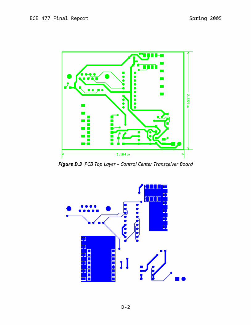
ECE 477 Final Report Spring 2005
rotate_left(); rotate_left(); //Map back from table 4 else if (table == 4) rotate_right(); rotate_right(); move_forward(30); rotate_left(); move_forward(120); rotate_left(); rotate_left();
***********************END of Microcontroller Source Code************************
*************************Start of GUI Source Code in VB**************************
' initialization of global variableDim newString As StringDim InArray(10, 1) As Integer 'instruction arrayDim InIndex As Integer 'to keep track which array index to be put inDim tablex(4) As Integer ' tables x coordinateDim tabley(4) As Integer ' tables y coordinateDim Opcode As Integer 'opcode from robotDim meter_robot As IntegerDim cm_robot As IntegerDim status As IntegerDim global_d As Integer 'to keep track of the direction of robotDim home As Integer 'to keep track if the robot is home
Private Sub Form_Unload(Cancel As Integer)Unload Form1
End Sub
Private Sub About_Click()frmAbout.ShowEnd Sub
'select tablePrivate Sub Command1_Click()
Dim Count As IntegerDim newString As StringDim firsttable As IntegerCount = 0
'check which tables are selectedFor i = 0 To 3
If Check1(i).Value = 1 ThenCount = Count + 1
F-20

ECE 477 Final Report Spring 2005
End IfNext i
If Count > 2 Then' error selecting more than two tables
For i = 0 To 3Check1(i).Value = FalseNext iCount = 0MsgBox ("You can only deliver to a maximum of two tables!"), vbOKOnly, "Error!"
ElseIf Count = 0 Then'No table selectedFor i = 0 To 3Check1(i).Value = FalseNext iCount = 0MsgBox ("You have to check at least one table!"), vbOKOnly, "Error!"
'correctElse
DisplayCount = 0
For i = 0 To 3
If Check1(i).Value = 1 And Count = 1 ThennewString = "Food is now being delivered to Table " & (i + 1)Text1.Text = Text1.Text + newString & "..."Check1(i).Value = 0Call SendBackup(i + 1)'put instructions into array and send themInIndex = -1Call calcroute(0, 0, 1, tablex(i + 1), tabley(i + 1))
InArray(InIndex + 1, 0) = 100InArray(InIndex + 1, 1) = 100
ElseIf Check1(i).Value = 1 And Count = 2 Then
If DisplayCount = 0 Then
'put instructions into array and send them, deliver to first tableInIndex = -1Call calcroute(0, 0, 1, tablex(i + 1), tabley(i + 1))
firsttable = inewString = "Food is now being delivered to Table " & (i + 1)
DisplayCount = DisplayCount + 1
ElseIf DisplayCount = 1 Then
'call calcroute to deliver to second table
F-21
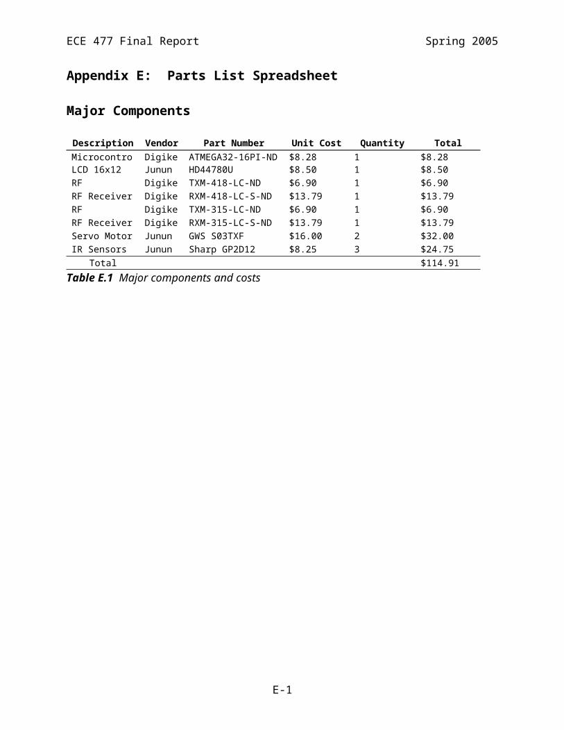
ECE 477 Final Report Spring 2005
Call calcroute(tablex(firsttable + 1), tabley(firttable + 1), 1, tablex(i + 1), tabley(i + 1))
InArray(InIndex + 1, 0) = 100InArray(InIndex + 1, 1) = 100
newString = newString + " and Table " & (i + 1)
End IfEnd IfNext i
' reset valuesFor i = 0 To 3Check1(i).Value = 0Table1 = iNext i
Count = 0'Text1.Text = Text1.Text + newString & vbCrLf
'Call SendInstruction
'enter = vbCrLf
End If
End Sub'this function sends command to the robot via RFPrivate Sub SendBackup(Tabl As Integer)Dim timeout As SingleDim sData As String ' Holds our incoming dataDim lHighByte As Long ' Holds HighByte valueDim lLowByte As Long ' Holds LowByte valueDim lWord As Long ' Holds the Word result
If Tabl = 1 Then
For i = 0 To 10timeout = TimerWhile Timer < timeout + 1DoEventsWendDebug.Print "sending"MSComm1.Output = Chr$(170) & Chr(240) & Chr$(85)Next i
DoMSComm1.InBufferCount = 0If MSComm1.InBufferCount = 3 Then Exit Dodummy = DoEvents()Loop Until Timer > timeout + 60
If MSComm1.InBufferCount = 3 Then
Debug.Print "get sth"sData = MSComm1.Input ' Get data (2 bytes)lHighByte = Asc(Mid$(sData, 2, 1)) ' get 1st byte
If lHighByte = 255 Then
Label5.Caption = "FOOD MISSING!!"
F-22

ECE 477 Final Report Spring 2005
ElseIf lHighByte = 153 Then
Label5.Caption = "OBSTACLE DETECTED, UNABLE TO RE-ROUTE"End IfEnd If
ElseIf Tabl = 2 Then
For i = 0 To 10timeout = TimerWhile Timer < timeout + 1DoEventsWendDebug.Print "sending"MSComm1.Output = Chr$(170) & Chr(15) & Chr$(85)Next i
DoMSComm1.InBufferCount = 0If MSComm1.InBufferCount = 3 Then Exit Dodummy = DoEvents()Loop Until Timer > timeout + 60
If MSComm1.InBufferCount = 3 Then
Debug.Print "get sth"sData = MSComm1.Input ' Get data (2 bytes)lHighByte = Asc(Mid$(sData, 2, 1)) ' get 1st byte
If lHighByte = 255 Then
Label5.Caption = "FOOD MISSING!!"ElseIf lHighByte = 153 Then
Label5.Caption = "OBSTACLE DETECTED, UNABLE TO RE-ROUTE"End IfEnd If
ElseIf Tabl = 3 Then
For i = 0 To 10timeout = TimerWhile Timer < timeout + 1DoEventsWendDebug.Print "sending"MSComm1.Output = Chr$(170) & Chr(146) & Chr$(85)Next i
DoMSComm1.InBufferCount = 0If MSComm1.InBufferCount = 3 Then Exit Dodummy = DoEvents()Loop Until Timer > timeout + 60
If MSComm1.InBufferCount = 3 Then
Debug.Print "get sth"sData = MSComm1.Input ' Get data (2 bytes)lHighByte = Asc(Mid$(sData, 2, 1)) ' get 1st byte
F-23
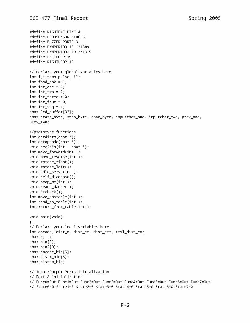
ECE 477 Final Report Spring 2005
If lHighByte = 255 Then
Label5.Caption = "FOOD MISSING!!"ElseIf lHighByte = 153 Then
Label5.Caption = "OBSTACLE DETECTED, UNABLE TO RE-ROUTE"End IfEnd IfElse
For i = 0 To 10timeout = TimerWhile Timer < timeout + 1DoEventsWendDebug.Print "sending"MSComm1.Output = Chr$(170) & Chr(218) & Chr$(85)Next i
DoMSComm1.InBufferCount = 0If MSComm1.InBufferCount = 3 Then Exit Dodummy = DoEvents()Loop Until Timer > timeout + 60
If MSComm1.InBufferCount = 3 Then
Debug.Print "get sth"sData = MSComm1.Input ' Get data (2 bytes)lHighByte = Asc(Mid$(sData, 2, 1)) ' get 1st byte
If lHighByte = 255 Then
Label5.Caption = "FOOD MISSING!!"ElseIf lHighByte = 153 Then
Label5.Caption = "OBSTACLE DETECTED, UNABLE TO RE-ROUTE"End IfEnd If
End IfEnd Sub
'old function that can send the instruction one by one to the robotPrivate Sub SendInstruction()Dim First As IntegerDim Second As IntegerDim Meter As DoubleDim sData As String ' Holds our incoming dataDim lHighByte As Long ' Holds HighByte valueDim lLowByte As Long ' Holds LowByte valueDim i As IntegerDim timeout As Single
i = 0Opcode = 15 'waitDebug.Print "send instruction is called"
While Not InArray(i, 0) = 100
Debug.Print "instruction!"
F-24

ECE 477 Final Report Spring 2005
Debug.Print i
Meter = InArray(i, 1) / 100' floor meterMeter = CDbl(CLng(Meter - 0.5))
First = InArray(i, 0) * 16 + MeterSecond = InArray(i, 1) Mod 100MSComm1.Output = Chr$(170) & Chr$(First) & Chr$(Second) & Chr$(85)Debug.Print "just send you a new INSTRUCTION, wait for acknowledgement"
timeout = Timer'check acknowledgement'Do'MSComm1.InBufferCount = 0'If MSComm1.InBufferCount = 4 Then Exit Do'dummy = DoEvents()'Loop Until Timer > Timeout + 2
'If MSComm1.InBufferCount = 4 Then
'sData = MSComm1.Input ' Get data (2 bytes)'lHighByte = Asc(Mid$(sData, 2, 1)) ' get 1st byte'lLowByte = Asc(Mid$(sData, 3, 1)) ' Get 2nd byte 'Opcode = (lHighByte And 240) / 16'meter_robot = lHighByte And 15'cm_robot = lLowByte'Debug.Print lHighByte'Debug.Print lLowByte
'End If
'Else'Debug.Print "I dun get 4 bytes!"
'End If
'If lHighByte = First And lLowByte = Second Then'VALID VALID VALID
'Debug.Print "acknowledgement received"
'check doneDebug.Print "start waiting for ur DONE"
timeout = Timer
DoMSComm1.InBufferCount = 0If MSComm1.InBufferCount = 4 Then Exit Dodummy = DoEvents()Loop Until Timer > timeout + 10
If MSComm1.InBufferCount = 4 Then
sData = MSComm1.Input ' Get data (2 bytes)lHighByte = Asc(Mid$(sData, 2, 1)) ' get 1st bytelLowByte = Asc(Mid$(sData, 3, 1)) ' Get 2nd byte Opcode = (lHighByte And 240) / 16meter_robot = lHighByte And 15
F-25
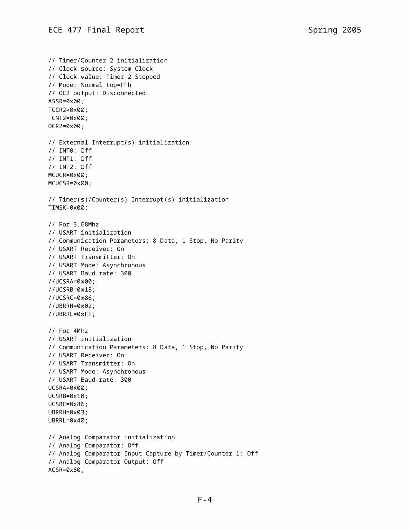
ECE 477 Final Report Spring 2005
cm_robot = lLowByte
'Debug.Print " and you should return OPCODE = 3!!!"'Debug.Print Opcode
If Not Opcode = 3 ThenDebug.Print "u didnt reply 3!!"ElseDebug.Print "You finish this instruction!!!"i = i + 1End If
Text1.Text = Text1.Text & ".."'VALID VALID VALIDElseDebug.Print "DIDNT GET CORRECT ACKNOWLEDGEMENT"End If
Wend
Text1.Text = Text1.Text & "Done!" & vbCrLfDebug.Print "FINISH ALL INSTRUCTIONS!!"End Sub
'call manual modePrivate Sub Command2_Click()If MSComm1.PortOpen = True ThenMSComm1.PortOpen = FalseEnd IfForm1.Visible = FalseForm2.Show
End Sub'connect to robotPrivate Sub Connect_Click()
If MSComm1.PortOpen = False Then MSComm1.CommPort = 1 MSComm1.Settings = "300,n,8,1" MSComm1.PortOpen = True ' Fire Rx Event Every Two BytesMSComm1.RThreshold = 3
' When Inputting Data Input 2 Bytes at a timeMSComm1.InputLen = 3
MSComm1.DTREnable = False
Else MsgBox ("Port already opened!"), vbOKOnly, "Error!"End IfEnd Sub
'disconnect to robotPrivate Sub Disconnect_Click()If MSComm1.PortOpen = True Then MSComm1.PortOpen = False
F-26
ECE 477 Final Report Spring 2005
Else MsgBox ("Port already closed!"), vbOKOnly, "Error!"End IfEnd Sub
Private Sub Form_Load()
' this function loads the coordinate from c:\sample.txt
Dim fso As New FileSystemObject Dim f As File Dim fsoStream As TextStream Dim wah() As String Dim strLine As String Dim i As Integer status = 0 tablex(1) = 20 tabley(1) = 20 i = 1 'On Error Resume Next 'Set f = fso.GetFile("C:\roboticwaitress\sample.txt") 'If f = Error Then 'Unload Form1 ' MsgBox ("Configuration File could not be found!"), vbOKOnly, "Error!" 'Else 'Set fsoStream = f.OpenAsTextStream(ForReading) ' Read the file line by line, debug.Printing the results to the Form 'Do While Not fsoStream.AtEndOfStream ' strLine = fsoStream.ReadLine ' wah = Split(strLine, ",") ' tablex(i) = wah(0) ' tabley(i) = wah(1) ' i = i + 1 'Loop 'fsoStream.Close Set fsoStream = Nothing Set f = Nothing Set fso = Nothing Text1.Text = Text1.Text & "Tables' coordinates loading from file...Done" & vbCrLf 'Call stupid'initialize direction and homeglobal_d = 1home = 1'End IfEnd Sub
Private Function BinaryToDecimal(Binary As String) As LongDim n As LongDim s As Integer
For s = 1 To Len(Binary)n = n + (Mid(Binary, Len(Binary) - s + 1, 1) * (2 ^ (s - 1)))Next s
BinaryToDecimal = nEnd Function'navigation alogorithmPrivate Sub calcroute(x1 As Integer, y1 As Integer, d As Integer, x2 As Integer, y2 As Integer)
F-27

ECE 477 Final Report Spring 2005
Dim difference(2) As IntegerDim position(2) As Integer
difference(0) = x2 - x1 difference(1) = y2 - y1 InIndex = InIndex + 1
'if on Y axis, travel the Y distance first' then travel the X
If x1 = 0 And y1 = 0 Then position(0) = 0 position(1) = 0 End If
If x1 = 0 Then If d = 1 Then If difference(1) > 0 Then 'travelling forward Debug.Print "Go forward " & difference(1) InArray(InIndex, 0) = 3 InArray(InIndex, 1) = difference(1) position(1) = position(1) + difference(1) Debug.Print "Current Position: " & position(0) & " " & position(1) Call calcroute(x1, y2, 1, x2, y2) ElseIf difference(1) < 0 Then 'travelling backwards Debug.Print "Turn 180 degrees, make d=3" Debug.Print "Go forward " & (-1) * difference(1) InArray(InIndex, 0) = 8 InArray(InIndex, 1) = (-1) * difference(1) position(1) = position(1) + difference(1) Debug.Print "Current Position: " & position(0) & " " & position(1) Call calcroute(x1, y2, 3, x2, y2) ElseIf difference(0) < 0 Then Debug.Print ("Turn -90 degrees, make d=4") Debug.Print "Go forward " & (-1) * difference(0) InArray(InIndex, 0) = 4 InArray(InIndex, 1) = (-1) * difference(0) position(0) = position(0) + difference(0) Debug.Print "Current Position: " & position(0) & " " & position(1) ElseIf difference(0) > 0 Then Debug.Print ("Turn 90 degrees, make d=2") Debug.Print "Go forward " & difference(0) InArray(InIndex, 0) = 5 InArray(InIndex, 1) = difference(0)
F-28

ECE 477 Final Report Spring 2005
position(0) = position(0) + difference(0) Debug.Print "Current Position: " & position(0) & " " & position(1) Else Debug.Print ("d1") End If ElseIf d = 2 Then If difference(1) > 0 Then Debug.Print ("Turn -90 degrees, make d=1") Debug.Print "Go forward " & difference(1) InArray(InIndex, 0) = 4 InArray(InIndex, 1) = difference(1) position(1) = position(1) + difference(1) Debug.Print "Current Position: " & position(0) & " " & position(1) Call calcroute(x1, y2, 1, x2, y2) ElseIf difference(1) < 0 Then Debug.Print ("Turn 90 degrees, make d=3") Debug.Print "Go forward " & (-1) * difference(1) InArray(InIndex, 0) = 5 InArray(InIndex, 1) = (-1) * difference(1) position(1) = position(1) + difference(1) Debug.Print "Current Position: " & position(0) & " " & position(1) Call calcroute(x1, y2, 3, x2, y2) ElseIf difference(0) < 0 Then Debug.Print ("Turn -180 degrees, make d=4") Debug.Print "Go forward " & (-1) * difference(0) InArray(InIndex, 0) = 8 InArray(InIndex, 1) = (-1) * difference(0) position(0) = position(0) + difference(0) Debug.Print "Current Position: " & position(0) & " " & position(1) ElseIf difference(0) > 0 Then Debug.Print "Go forward " & difference(0) InArray(InIndex, 0) = 3 InArray(InIndex, 1) = difference(0) position(0) = position(0) + difference(0) Debug.Print "Current Position: " & position(0) & " " & position(1) Else Debug.Print ("d2") End If ElseIf d = 3 Then If difference(1) < 0 Then Debug.Print "Go forward " & (-1) * difference(1) InArray(InIndex, 0) = 3 InArray(InIndex, 1) = (-1) * difference(1) position(1) = position(1) + difference(1) Debug.Print "Current Position: " & position(0) & " " & position(1)
F-29
ECE 477 Final Report Spring 2005
Call calcroute(x1, y2, 3, x2, y2) ElseIf difference(1) > 0 Then Debug.Print ("Turn 180 degrees, make d=1") Debug.Print "Go forward " & difference(1) InArray(InIndex, 0) = 8 InArray(InIndex, 1) = difference(1) position(1) = position(1) + difference(1) Debug.Print "Current Position: " & position(0) & " " & position(1) Call calcroute(x1, y2, 1, x2, y2) ElseIf difference(0) < 0 Then Debug.Print ("Turn 90 degrees, make d=4") Debug.Print "Go forward " & (-1) * difference(0) InArray(InIndex, 0) = 5 InArray(InIndex, 1) = (-1) * difference(0) position(0) = position(0) + difference(0) Debug.Print "Current Position: " & position(0) & " " & position(1) ElseIf (difference(0) > 0) Then Debug.Print ("Turn -90 degrees, make d=2") Debug.Print "Go forward " & difference(0) InArray(InIndex, 0) = 4 InArray(InIndex, 1) = difference(0) position(0) = position(0) + difference(0) Debug.Print "Current Position: " & position(0) & " " & position(1) Else Debug.Print ("d3") End If ElseIf d = 4 Then If difference(1) > 0 Then Debug.Print ("Turn 90 degrees, make d=1") Debug.Print "Go forward " & difference(1) InArray(InIndex, 0) = 5 InArray(InIndex, 1) = difference(1) position(1) = position(1) + difference(1) Debug.Print "Current Position: " & position(0) & " " & position(1) Call calcroute(x1, y2, 1, x2, y2) ElseIf difference(1) < 0 Then Debug.Print ("Turn -90 degrees, make d=3") Debug.Print "Go forward " & (-1) * difference(1) InArray(InIndex, 0) = 4 InArray(InIndex, 1) = (-1) * difference(1) position(1) = position(1) + difference(1) Debug.Print "Current Position: " & position(0) & " " & position(1) Call calcroute(x1, y2, 3, x2, y2) ElseIf difference(0) < 0 Then
F-30

ECE 477 Final Report Spring 2005
Debug.Print "Go forward " & (-1) * difference(0) InArray(InIndex, 0) = 3 InArray(InIndex, 1) = (-1) * difference(0) position(0) = position(0) + difference(0) Debug.Print "Current Position: " & position(0) & " " & position(1) ElseIf difference(0) > 0 Then Debug.Print ("Turn -180 degrees, make d2") Debug.Print "Go forward " & difference(0) InArray(InIndex, 0) = 8 InArray(InIndex, 1) = difference(0) position(0) = position(0) + difference(0) Debug.Print "Current Position: " & position(0) & " " & position(1) Else Debug.Print ("d4") End If End If Else ' not on Y axis
If d = 4 Then If x1 < 0 Then Debug.Print ("Turn 180 degrees, make d=2") Debug.Print "Go forward " & (-1) * x1 InArray(InIndex, 0) = 8 InArray(InIndex, 1) = (-1) * x1 position(0) = position(0) - x1 Debug.Print "Current Position: " & position(0) & " " & position(1) Call calcroute(0, y1, 2, x2, y2) ElseIf x1 > 0 Then Debug.Print "Go forward " & x1 InArray(InIndex, 0) = 3 InArray(InIndex, 1) = x1 position(0) = position(0) + x1 Debug.Print "Current Position: " & position(0) & " " & position(1) Call calcroute(0, y1, 4, x2, y2) Else Debug.Print ("Something has gone wrong") End If ElseIf d = 2 Then If x1 < 0 Then Debug.Print "Go forward " & (-1) * x1 InArray(InIndex, 0) = 3 InArray(InIndex, 1) = (-1) * x1 position(0) = position(0) - x1 Debug.Print "Current Position: " & position(0) & " " & position(1) Call calcroute(0, y1, 2, x2, y2) ElseIf x1 > 0 Then
F-31

ECE 477 Final Report Spring 2005
Debug.Print ("Turn -180 degrees, make d=4") Debug.Print "Go forward " & x1 InArray(InIndex, 0) = 8 InArray(InIndex, 1) = x1 position(0) = position(0) - x1 Debug.Print "Current Position: " & position(0) & " " & position(1) Call calcroute(0, y1, 4, x2, y2) Else Debug.Print ("Something has gone wrong") End If ElseIf d = 3 Then If x1 < 0 Then Debug.Print ("Turn -90 degrees, make d=2") Debug.Print "Go forward " & (-1) * x1 InArray(InIndex, 0) = 4 InArray(InIndex, 1) = (-1) * x1 position(0) = position(0) - x1 Debug.Print "Current Position: " & position(0) & " " & position(1) Call calcroute(0, y1, 2, x2, y2) ElseIf x1 > 0 Then Debug.Print ("Turn 90 degrees, make d=4") Debug.Print "Go forward " & x1 InArray(InIndex, 0) = 5 InArray(InIndex, 1) = x1 position(0) = position(0) + x1 Debug.Print "Current Position: " & position(0) & " " & position(1) Call calcroute(0, y1, 4, x2, y2) Else Debug.Print ("Something has gone wrong") End If ElseIf d = 1 Then If x1 < 0 Then Debug.Print ("Turn 90 degrees, make d=2") Debug.Print "Go forward " & (-1) * x1 InArray(InIndex, 0) = 5 InArray(InIndex, 1) = (-1) * x1 position(0) = position(0) - x1 Debug.Print "Current Position: " & position(0) & " " & position(1) Call calcroute(0, y1, 2, x2, y2) ElseIf x1 > 0 Then Debug.Print ("Turn -90 degrees, make d=4") Debug.Print "Go forward " & x1 InArray(InIndex, 0) = 4 InArray(InIndex, 1) = x1 position(0) = position(0) + x1 Debug.Print "Current Position: " & position(0) & " " & position(1) Call calcroute(0, y1, 4, x2, y2)
F-32

ECE 477 Final Report Spring 2005
Else Debug.Print ("Something has gone wrong") End If End IfEnd If
Exit Sub
End Sub
****************************End of GUI Source Code*****************************
F-33

ECE 477 Final Report Spring 2005
Appendix G: User Manual
Product Description
We are delighted that you have chosen to purchase the “I, Robotic Waitress” for your food
service needs. The “I, Robotic Waitress” will facilitate easy delivery of food at your restaurant
using Radio Frequency (RF) communication. The Waitress receives instructions from a control
center specifying which table to deliver food to. All food deliveries are made from a specified
central location. The control center consists of an RF transmitter (315 MHz) and a receiver (418
MHz) module packaged together on one printed circuit board. The control center also has a red
power Light Emitting Diode (LED), a green RF receiver LED and a yellow RF transmitter LED.
When the power switch is on, the red LED is lit while the green and yellow are lit when the
control center is receiving and transmitting RF data respectively. A Visual Basic application
running on a computer sends instructions to the Waitress using the Universal Asynchronous
Receiver/Transmitter (UART) controller on the computer and via the RF transmitter module on
the control center. The control center operates on a 9VDC battery.
When the Waitress receives instructions, it navigates to the specified table and attempts to avoid
obstacles in its path. In case an obstacle cannot be avoided, the Waitress sounds an alarm and
sends an RF message to notify the control center of its current status. Also, if the Waitress
detects that the food is missing from the tray before its gets to the specified table location, it
sounds an alarm and sends a message to notify the control center of the mishap. Upon
successfully delivering food to a table, the Waitress returns to the central location from where all
deliveries are made. While executing received instructions, the Waitress displays status
messages, such as the operation being performed, on the liquid crystal display (LCD). The
Waitress’ wheels are powered by four 1.5V AA batteries. The Waitress’ other major components
comprising the RF transmitter (418 MHz) and receiver (315 MHz), the LCD, the micro-
controller and the buzzer are all powered by a 9VDC battery.
Using the Waitress requires a simple installation of the Visual Basic control center
program on a computer and essentially connecting the required components.
G-1

ECE 477 Final Report Spring 2005
Product Illustration:
Figure G.1 Kit Contents
Figure G.2 Front View with Right, Left and Food Sensors
G-2

ECE 477 Final Report Spring 2005
Figure G.3 Bottom View – AA batteries
Figure G.4 Side View
Figure G.5 Back View
G-3

ECE 477 Final Report Spring 2005
Figure G.6 Control Center Transceiver
Figure G.7 Software Screen Shot
G-4

ECE 477 Final Report Spring 2005
Product Setup Instructions
Step1. Take out the robot, transceiver, serial cable, and installation CD out of the box. If your
robot has not already been programmed with your restaurant’s table layout, please do so by
sending it to an authorized deal or contact tech-support for further instructions on doing this
yourself.
Step 2. Install the software onto your computer. Insert the installation CD you’re your CD drive.
As a quick reminder, the provided software only runs under a Windows XP/ME/2000 platform.
After the CD has been inserted, go to ‘Start’-‘Run’ and type D:\setup.exe.
Step 3.After the installation of the software for the Control Center has been completed, proceed
by placing all the batteries. Place a 9V battery on the battery holder located above the servo
motors. Place another four AAA batteries into the battery pack located at the bottom of the robot.
Plug in another 9V battery into the adapter for the transceiver module provided.
Figure G.8 Bottom View Figure G.9 Side View
Step 4. Connect the transceiver to the computer with the serial cable. Make sure the serial cable
is properly plugged in. The serial port must also be plugged into COM port 1. Then, power up
the transceiver.
Step 5. Power up the Robotic Waitress and the servo motors by switching the two switches
located at the back of the robot.
G-5

ECE 477 Final Report Spring 2005
Figure G.10 Back View
Step 6.The Robotic Waitress is now ready to be used.
Tips Before Use:
- Align the robot before any instruction has been sent
- remove any obstacles in front of the robot
Product Use Instructions: There are a total of 4 switches on the robot for different purposes.To turn on/off the power of the robot:
Turn on/off the switch labeled "power" on the back side of the robot.
To turn on/off the motors of the robot:
Turn on/off the switch labeled "motors" on the back side of the robot.
To turn on/off the backlight of the LCD display of the robot:
Turn on/off the switch labeled "backlight" on the left side of the robot.
Figure G.11 Side View
To reset the robot:
Press the switch labeled "reset" on the left side of the robot.
G-6

ECE 477 Final Report Spring 2005
Once the software has been installed, you can easily send instructions to the robot. The
user interface consists of a menu, a status display window, check boxes for tables, and a "Go!"
button.
Figure G.12 Software Screen Shot
To deliver food to a table do the following:
Step1. Turn on the power of the robot and its motors
(Note: It's optional to turn on the backlight of the LCD display)
Step2. Put the food on the tray mounted on top of the robot
Step3. Open the software
Step4. Click on "Connect to robot..." button in the software's menu
Step5. Check the box labeled with the table number
(Note: You can only deliver food to one table each time)
Step6. Click the "Go!" button
The Robot's status will be displayed on the status window. In the event that the robot has
detected an obstacle in its path and is unable to re-route, the robot will go back to the starting
position automatically and an alert message will be displayed on the status window. In the event
that the food is taken away from the robot's tray on its way to the table, an alert message will be
displayed on the status window.
To disconnect from the robot:
Click on "Disconnect to robot..." button in the software's menu
(Note: It's recommended that you disconnect from the robot before you close the software)
G-7

ECE 477 Final Report Spring 2005
Troubleshooting GuideRobot ProblemsProblem Cause SolutionLCD display does not display anything
Power is not turned on
- Switch the power switch ON
Insufficient battery voltage
- Replace the 9V battery
Poor contact between battery and terminals
- Polish the terminals with a soft cotton swab before placing or replacing the battery
Robotic Waitress does not run in a straight line anymore
Worn out rubber traction bands
- Replace the rubber traction bands
Insufficient battery voltage
- Replace the AA batteries located at the bottom of the robot (Rechargeable batteries are recommended)
After boot up, the Robotic Waitress moves randomly
Obstacle sensors are blocked
- check for objects within 20 cm of the obstacle sensors- re-set the robot after obstacles have been removed
Robot is receiving junk data
- Move robot to an electronic-free environment and restart the robot- If problem persists contact tech-support
Robotic Waitress does not move even after instructions have been sent through the computer
Robot is not receiving instructions
- Check the status displayed on the LCD to see if instructions are being received by the robot- If no receiving status is displayed, move transceiver closer to the robot
The food tray is empty
- Place food on the tray before any instruction is sent. The robot does not move initially until food is present on the tray
Robotic Waitress has been just turned on, but the robot does not respond after an instruction has been sent from the pc
The self diagnostic test is still running
- After booting up the robot, allow 10 seconds for the robot to run the self diagnostic test before sending it any instructions
Servos are not powered up
- Turn the switch ON for the Servo motors located at the back of the robot
After the motors are powered, the robot moves slightly to a side
Not a problem - This is normal at power up. We recommend re-aligning the robot every time the robot leaves the starting point
G-8

ECE 477 Final Report Spring 2005
Control Center & Software Problems
Problem Cause SolutionError appears while installing the software
Running the software under incorrect platform
- The current software only runs in Windows XP/ME/2000
Can’t connect to the Robotic Waitress with the Control Center software
Serial cable is not connected properly
- Check the serial cable connection. - Make sure it is properly connected at the transceiver and the computer’s serial port.
Serial cable is connected to the wrong port
- Connect the serial cable to port 1 on the computer
Serial port is being used
- Make sure the serial port is not used by any other programs.- Close all programs that might be using the serial port
Control Center software doesn’t seem to be sending or receiving information
Serial cable is not connected properly
- Check the serial cable connection. - Make sure it is properly connected at the transceiver and the computer’s serial port.- Connect the serial cable to port 1 on the computer
Transceiver and/or robot is/are not powered
- Check the TX and RX LED’s- Turn the power switch ON for the transceiver, the robot, and the motors
Robotic Waitress does not respond to instructions sent by the software
Transceiver and/or robot is/are not powered
- Check the TX and RX LED’s on the transceiver and robot to make sure information is being sent and received- Turn the power switch ON for the transceiver, the robot, and the motors
Robot is out of communication range
- Check the TX and RX LED’s on the transceiver and robot to make sure information is being sent and received- Re-send instructions to the robot at a closer distance until proper communication has been achieved
For any other problems, contact the company’s tech support. Any unauthorized modification of the products will void the warranty.
G-9

ECE 477 Final Report Spring 2005
Appendix H: FMECA Worksheet
Failure No.
Failure Mode Possible Causes Failure Effects Method of Detection
Criticality Remarks
A1 VCC = 0 Failure of any component within block A.
Overall design failure
Observation Low
A2 VCC > 5V Failure of U1 (LM7805C)
System wide failure, other components could be damaged, unpredictable behavior
Observation High Can be prevented by a fuse, diode.
A3 PW1 = 0V Failure of C20, J2 Loss of power to servos, no motion robot
Observation of robot motion.
Low
B1 Random output of pins PD0, PD1
Failure of MCU1, software problem
No RF communication
Observation Low Could be detected using external watchdog.
B2 Random output of pins PA0, PA1, PA4, PA5, PA6, PA7
Failure of MCU1, software problem
Unpredictable LCD output
Observation of LCD
Low Could be detected using external watchdog.
H-1

ECE 477 Final Report Spring 2005
B3 Uncontrolled output of pins PC3, PC4, PC5, PC1, PC2,PD4, PD5
Failure of MCU1, software problem
Loss of servo operation, unpredictable obstacle, food & tilt sensor outputs
Observation of LCD
High Could be detected using external watchdog.
C1 IR sensors not working
Failure of J5, J6, J7, C6, C8, C9
Inability to detect obstacles precisely, food on tray
Observation High
D1 RF receiver modules not working
Failure of U5, U7 Inability to receive instructions from control center
Observation Low
D2 RF transmitter modules not working
Failure of U4, U8 Inability to send alerts/messages to the control center
Observation Low
H-2