Embed Size (px)
Citation preview

EE 462 Final Project Report:
Electric Upgrades- Supercapacitor Electric
Bicycle
John Chen
Wilson Fletcher
Spencer Esparza
Advisor:
Professor Art MacCarley
June 15, 2018

1
Table of contents
Section Page
Abstract 2
Introduction 2
Background 3
Research 5
Design Requirements 6
Design Results 9
Development/ Testing 15
Parts List 16
Possible Improvements 17
Conclusion 18
References 19
Senior Project Analysis 20
2
Abstract
Supercapacitors provide high current capabilities compared to conventional lithium-ion
batteries, allowing for fast charging and discharging of electrical energy. This project seeks to
test the benefits of supercapacitors in an electric bicycle unit in order to gain higher regenerative
energy. The main components of the bicycle are its regenerative motor, supercapacitor array, and
motor controller. Developing the project will provide data on the feasibility of using alternative
battery storage and charging.
Introduction:
The key to any successful consumer product is to first find an audience, a market to pitch
and sell to. It requires a unique solution to a problem that a large population experiences. As the
world continues to develop a large concern of the future includes the necessity of easy and
ethical transportation. Following the trends of many other industries including the automotive
and mass transit fields, exploring and developing upon the possibilities of electronic
transportation has opened opportunities to a more renewable future.
One of the largest issues observed in much of the power electronics field today is energy
storage. Rechargeable batteries have been a simple solution for many years and although their
technology is improving a large concern is the amount of energy converted to heat as a
byproduct of the battery’s daily functions. Since the 1950s capacitors have been studied as an
energy storage device. Although they posses unappealing traits for some applications capacitors
do have great potential uses in many situations. One such situation is in the regeneration of
energy.

3
Background:
Supercapacitors (or “ultracapacitors”) have specifically interesting characteristics when it
comes to rapid energy storage and release. Early evidence of the capabilities of these
supercapacitors is found in a racecar produced by Toyota in 2007. That year the hybrid Toyota
Supra HV-R coupe won a 24 hour endurance race by a respectable 19 laps.[6] This is a result of
the regenerative braking function of the automobile. Instead of the conventional disk brakes of a
normal car which convert speed into heat through friction this hybrid car was able to convert its
speed into electrical potential. As seen in modern hybrid cars, when decelerating an electric
engine has the capability to accept electric energy back into storage for future use instead of
dissipating the energy like waste. A distinct advantage of these supercapacitors is that they are
far more efficient through their charge and discharge cycles than a conventional battery.
Although they may not power a vehicle for long, their ability to quickly accept and redirect
energy is astounding. Toyota realized this and solved a large waste in potential in the fast paced
world of racing. In 2013, “ultracapacitors for an energy-saving braking energy recuperation
system [were installed] on light rail vehicles operated by the Portland, Oregon area’s Tri-County
Metropolitan Transportation District.”[7] This instalment plans to aid in keeping operation costs
to a minimum while simultaneously creating a more energy efficient and eco-friendly form of
transportation.
These examples along with many more show that supercapacitors have a place in the
future of hybrid and electric transportation systems. By observing the practical uses of these
components a goal was created to incorporate supercapacitors into a personal transportation
vehicle; one that requires no external power source but can run purely on manpower and assist
by making a more efficient system. The most apparent way to accomplish this task was to look
into the electric bicycle industry. Regenerative braking already exists in ebikes but is rarely used
because it is extremely inefficient in regenerating batteries and puts more of a burden on
pedaling.[8] If supercapacitors could be implemented to make the regeneration aspect more
efficient and just after assist with acceleration, much like the Toyota Supra, then a much easier
ride can be managed. This may also open up possibilities of riding in much more gradient cities.

4
The goal of this project is to incorporate supercapacitors to operate with an electronic bicycle
and create an efficient regeneration and acceleration system.

5
Research:
When beginning this project, one question that our group had was how does the energy
density of a supercapacitor system compare to a typical electric bicycle powered by a lithium-ion
battery. To calculate this, we first needed to calculate the energy density of our 10 series
capacitor system. By using U = ½ CV2 , it was calculated that at full charge (2.7V per cell), the
supercapacitors would contain 36450J of energy. This can be converted to watt-hours and comes
out to 10.125 Wh of total energy. This can be compared to a production lithium-ion battery
which contains 400 Wh of energy. [1] The weight of this 400W lithium-ion battery came out to
2.6 kg. A single supercapacitor weighs 260g [2] so 10 in series would weigh 2.6 kg. This results
in 153.8 Wh/kg for the battery and 3.9 Wh/kg for the supercapacitor system. The average
distance an ebike travelling on flat ground at 14 mph with a passenger weighing 165 lbs using a
lithium-ion pack is 58 miles [5]. When connected to the supercapacitor system, this distance is
reduced to only 1.58 miles (assuming all charge from the capacitors is used). The battery system
also does not require a direct drive motor which a supercapacitor system needs to capture
regeneration. A 500w direct drive motor weighs 5.8 kg [3] whereas a 500w geared dc motor
weighs 4.26 kg [4]. This additional 1.54kg reduces the Wh/kg of the supercapacitor system to
2.45.
Another factor that needed to be taken into account when calculating the total expected
distance from a full charge on the capacitors was the necessity to step the capacitor voltage up to
36v in order for use with the controller. Due to conservation of energy, as the voltage of the
supercapacitors began to sag, the current directed through the DC-DC converter would need to
increase in order to deliver the same power. The power requirements depend on the weight of the
passenger, the incline of the riding surface, and the desired speed. Even though the chosen motor
was rated for 500W, this power output was never achieved. In order for the controller to deliver
500W, the current supplied from our DC-DC converter would need to be 12.5A @ 40V. This
would require the fully charged capacitors to supply 18.5A @ 27V with no loss in the DC-DC
converter in order to achieve this output power. The DC-DC used in this project had a maximum
current rating of 20A however it was very difficult/dangerous to keep the supercapacitors at their
max charge as they had leakage currents (~2.7 mA at 25 C) [2] as well as the controller drew

6
~200mA of current. This caused the input voltage to quickly sag below 27V and cause the
required current through the DC-DC to increase past its rating.
Design Requirements:
Table 1. Design Requirements
Requirement Explanation
Direct Drive Motor Direct drive motors can be used as both a
motor and a generator. When coming to a
stop, they act as a generator returning energy
to the capacitors. During acceleration they
draw energy from the capacitors and act as a
motor.
Controller with regeneration capabilities The motor selected needs to have the ability
to capture the back emf and return it to the
capacitors.
10 Capacitors The starting voltage needs to be able to be
stepped up to the controller voltage with as
little extra weight as possible. 10 capacitors
would provide a maximum of 27V at full
charge, which can be boosted through a
DC-DC converter to 40V (Controller input).
Balancing Mosfets for Supercapacitors A mosfet-based balancing system is required
in order to keep the ultracapacitors at similar
voltages. This allows for all the
supercapacitors to be charged to their
maximum state without exceeding any
individual capacitor ratings.

7
Arduino-Based Throttle Regulation The arduino takes in voltages from both the
twist grip throttle and thumb brake and
ensures that the output voltage corresponds to
the intended user input. The voltage range for
the controller input is 0-3.5V.
DAC adapter for arduino The arduino natively outputs a PWM signal to
simulate analog. This was unacceptable for
the controller input and needed to be a pure
analog input. Using SPI, the DAC was
interfaced with the system in order to provide
this output.
External power for controller and arduino
circuitry
The external battery allows the controller to
stay on and powered even if the capacitors
drop below a certain threshold to power the
DC-DC. This allows the bicycle to
re-generate energy from no initial charge on
the capacitors.
Spring compression for capacitor enclosure Due to the fact that the supercapacitors were
intended to be welded together, there was no
intuitive alternative for connection. The final
design included a ¾ inch pipe with springs at
both ends to hold the capacitors within the
enclosure using pressure, ensuring a solid
contact between each tab of the capacitors.
Voltage tap wires for capacitors Each capacitor has a voltage tap at the
positive and negative terminals of the
capacitor in order to properly monitor and

8
balance the capacitor.
Separate Throttle and Brake Due to the fact that most off-the-shelf
throttles use a hall effect sensor in order to
generate an output voltage, it was impossible
to modify one in order to achieve voltage
levels below ~0.7V. This is why two separate
throttles were interfaced with an arduino in
order to create the throttle and brake
combination.

9
Design Results:
Figure 1: Electrical Diagram
The finalized design is seen in figure 1 above. The total number of capacitors was doubled in the
later stages of the project in order to allow for a higher input voltage into the DC-DC converter
which has a lower voltage cutoff of 8V. This DC-DC converter stepped the voltage up to 40 V
which was usable by both the motor controller and motor. A separate 22V lithium polymer
battery fed into a buck converter which stepped the voltage down to 12V which can be used by
both the arduino, relay, and controller to provide power to the controller when no charge remains
in the capacitors. The state of the controller was dictated by a twist grip and thumb throttle
combination. From the specification of the controller, the throttle input voltage from 0-1V
represented regeneration. The range from 1-4V represented forward thrust from the motor. This
was achieved by taking the signals from the throttle input and modifying them with an arduino in
order to get the appropriate voltage for the desired response. The regeneration draw from the
motor intensified as the voltage approached 0 making it a variable braking system. As the twist
grip throttle was actuated further forward, voltage increased toward 4 the current draw increased
causing greater acceleration. During forward motion, power was drawn directly from the DC-DC

10
converter and therefore the relay was in the state to draw power from this DC-DC. During
regeneration, the DC-DC controller was excluded and the return power was hooked up directly
between the regeneration of the motor controller and the ultracapacitors. Due to the fact that at
no load, the reverse voltage of the controller was 58V in regen, the voltage will always be higher
than our capacitor bank. Therefore it was possible to hook the regen wires directly to the
capacitor bank bypassing any reverse DC-DC conversion.
Figure 2: Capacitor Design
The finalized capacitor design is seen in figure 2 above. This design implemented the use of two
springs at either end of the tube, forcing the capacitor contacts together. As stated earlier, the
capacitors were meant to be laser welded together however we did not have access to this
technology for this project so this was the solution we came up with. Each capacitor has a
voltage tap wire seen above which can be used to monitor and balance the capacitors.
11
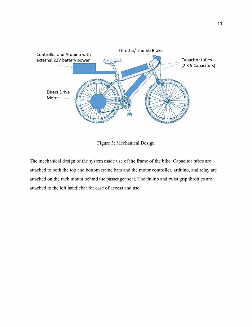
Figure 3: Mechanical Design
The mechanical design of the system made use of the frame of the bike. Capacitor tubes are
attached to both the top and bottom frame bars and the motor controller, arduino, and relay are
attached on the rack mount behind the passenger seat. The thumb and twist grip throttles are
attached to the left handlebar for ease of access and use.
12
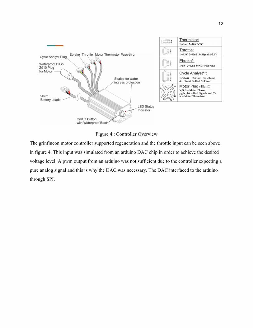
Figure 4 : Controller Overview
The grinfineon motor controller supported regeneration and the throttle input can be seen above
in figure 4. This input was simulated from an arduino DAC chip in order to achieve the desired
voltage level. A pwm output from an arduino was not sufficient due to the controller expecting a
pure analog signal and this is why the DAC was necessary. The DAC interfaced to the arduino
through SPI.

13
Figure 5 : Arduino Connections
Figure 5 is a schematic outlining the physical arduino connections made between the throttles,
MCP4921 DAC chip, and the relay.
Figure 6 : Capacitor Balancing System

14
The capacitor balancing system made use of the ALD810023 and ALD910023 supercapacitor
auto balancing MOSFET array. Each SAB MOSFET features a precision gate threshold voltage
in the Vt mode which is 2.3V when the gate-drain source terminals are connected together at a
drain-source current of IDS = 1uA. Different Vin produces an output current characteristic and
results in a variable resistance value that varies in value exponentially with Vin. This Vin when
connected across each supercapacitor in a series, balances each supercapacitor to within its
voltage and current limits [9].

15
Development/Testing:
While designing and assembling the bicycle several problems arose. The first issue showed in
the variable voltage of a capacitor powering a fixed voltage controller. This issue took the better
part of the time for this project in order to research and discover the best solution. Compromises
for both efficiency through the DC-DC converter and capacitance of the bank were made. These
compromises resulted in the most functional and efficient form of what was set out to be
accomplished.
Another issue occurred during assembly that caused the motor to jolt on and off. After a
thorough analysis and rewiring of a greater part of the system it turned out to be a severed wire
near the hub of the wheel. This wire was fixed and a modification to the casing was made to
better protect the fragile wires and reduce stress on the joint. This issue repeated upon adding the
forward throttle and brake. The cause of this problem was due to a pulse width modulated signal
output from the throttles. To fix this, a digital to analog converter allowed a steady signal to
reach the controller.
The previous issue of a jumpy operation occurred again later on in the project. Testing
with a power supply however made the motor run properly so the issue was cornered to the
capacitor bank. Going into the project it was known that these capacitors were purposed for laser
welding. Not having the time or capability to do so meant the bank would have to rely on a face
to face contact of the capacitors. Analysing the voltage across the bank gave good results of
about 20V but when we analysed the current draw from the bank of about 150 mV it became
obvious that there was a bad connection in the bank. After a meticulous reassembly of the
capacitor bank the bike functioned properly. In the second revision of the capacitor bank design,
springs were used to pressurize the contacts together to provide resistance during bumps and jolts
an electric bike experiences.
Another issue which presented itself through testing the first generation capacitor bank
was the voltage tap wires, which allowed the user to read the individual voltages of each
capacitor, coming loose and eliminating the ability to properly balance the cells. The solution to

16
this was to solder wires directly to a copper plate which was then inserted between each contact
of the capacitors.
When testing the first generation bicycle, the capacitors were deliberately undercharged
due to the fact that there was no protection circuitry on any of the capacitors to prevent
overvoltage. After extensive research, it was determined that a Supercapacitor Auto Balancing
Mosfet system was the optimal solution to guarantee that none of the cells exceeded their 2.7V
limit. In future tests, the bicycle would hold full charge to maximize energy storage for travel.
Parts List:
Table 2. Bill of Materials
Item Quantity Link Price
Bicycle 1 -- $150
Supercapacitor 10 -- $400
Direct Drive Motor 1 $150
12V - 40V Boost 1 $17
Motor Controller 1 $130
Capacitor Enclosure 2 $50
Misc Electronic Parts -- -- $100
Total $997

17
Possible Improvements:
With the main functionality of the electric bicycle completed, there are several
optimizations and aesthetic improvements to be made. Starting with the capacitor encasing, the
current setup is a pvc pipe used to enclose 5 capacitors and ensure proper electrical connection.
In order to differentiate this product from regular electric bicycles, an encasing that reveals the
supercapacitors allows for consumers to quickly notice the difference in this product. The
benefits to a clear encasing are aesthetics and advertisement. This would let people easily spot
the supercapacitors and perhaps increase interest in the product.
A second alternative encasing for the supercapacitors would be within the bicycle frame.
This version would require extra mechanical engineering and manufacturing to create this
bicycle frame specification. The benefit of this is to reduce volume. With 10-20 supercapacitors,
encasings take up significant space in between the bicycle frame. If a portion of the bicycle
frame was hollow, the capacitors would be able to fit inside and not need to be spread around the
bicycle. The downside to the frame idea is that the frame would need to be thicker in order to fit
capacitors inside. There would be production problems to solve in the future if the product
design were to use this style. There are few, if any, current bicycle frame manufacturers that
create this large hollow frame for these capacitors. In the end, this is one proposed encasing style
out of several.
Continuing on aesthetic improvements, the prototype bicycle requires its wires to be
cleaned up and managed. In the future iteration of the electrical design, the wires will be tightly
managed and unobstructive. The bicycle frame would have wire management attachments that
channel the wires from one part of the bicycle to another. For instance, the bicycle handle
controls need to attach to the controller in the rear. The acceleration and brake wires would be
combined in a single wire, along the frame of the bicycle, and reach the rear where the controller
is.
In order to appeal to customer needs, the bicycle’s weight and voltage rating need to be
optimized. A majority of the weight in the bicycle is from the regenerative motor. Ideally, the
motor should be as light as possible. The current motor could be replaced by a lighter one found
18
in the market in order to reduce weight. The bicycle frame is also a portion of the total weight
that can be reduced. Carbon fiber would be ideal as a frame material but at a high cost. The
supercapacitors are mandatory additional weight however.
Using only supercapacitors has proven to be possible. However, a hybrid
battery-capacitor system may yield some benefits. The extra battery can act as a backup to the
main capacitor energy storage as well as a power source for the controller unit. For example, the
motor can switch to the battery when the capacitors deplete and switch back to the capacitors
when they regenerated back enough energy. The cost of the backup battery can be significant so
it should be considered when deciding to add this feature.
Conclusion:
With the completion of a prototype supercapacitor electric bicycle, the project now
moves onto a refining phase. The implementation of the capacitors and motor is a proof of
concept and will be further advanced through research and development for customer
specifications and project optimizations. Functionally, the project is working with all the parts
together. The measurements during development show that this project is comparable to a typical
battery powered electric bicycle. In the future, the goal of this project is to create a consumer
product to put into the market. Adding features and improving upon the prototype will help
finalize a marketable product.

19
References
[1] https://www.bosch-ebike.com/us/products/batteries/
[2]https://www.mouser.com/datasheet/2/257/Maxwell_K2Series_DS_1015370-4-1179730.pdf
[3] https://www.ebikekit.com/products/rear-500w-heavy-duty-direct-drive-motor
[4]https://www.ebikekit.com/collections/e-bikekit-performance-no-battery/products/e-bikekit-per
formance-rear-no-battery
[5] https://www.bosch-ebike.com/us/service/range-assistant/
[6] https://www.scientificamerican.com/article/the-dark-horse-in-race-to/
[7]https://www.edn.com/electronics-blogs/powersource/4413126/Ultracapacitors-in-light-rail-reg
enerative-braking-system
[8] https://www.evelo.com/blog/why-dont-more-bikes-use-regenerative-braking/
[9] https://www.mouser.com/datasheet/2/8/ALD810023-464306.pdf
[10] Toxic Gas Emissions from Damaged Lithium Ion Batteries—Analysis and Safety
Enhancement Solution, [Online]. Available: www.mdpi.com/2313-0105/2/1/5/pdf [Accessed 26 November 2017]. Toxic emissions from improperly cared for Li-Po batteries
20
Analysis of Senior Project
Project Title: Electric Upgrades - Supercapacitor Electric Bicycle
Student Names: John Chen, Wilson Fletcher, Spencer Esparza
Advisor’s Name: Professor Art MacCarley
Summary of Functional Requirements:
This project will implement a supercapacitor array on an electric bicycle with a regenerative
motor. The system will power the motor when the user turns a throttle and set the motor in
forward mode and regenerate electrical energy when braking and activating regeneration mode.
The motor controller will take in the user inputs and manage the boost converter powering the
motor. The supercapacitor array will also have a protection circuit to prevent overloading.
Primary Constraints:
The primary constraints of this project are reliability, functionality, and cost. The controller and
motor must be able to reliably switch from regeneration and forward mode upon the user’s
control. For function, the power provided and regenerated by the supercapacitors must be
optimized in order to increase efficiency. The cost of the project must be as low as possible, with
the total cost being under $1000. With a lower total cost, the marketability of this product will
compete as an alternative to current electric bicycles.
Economic:
Introducing a supercapacitor bicycle means entering an established electric bicycle market.
Electric bicycles cost upwards of $1000 to $10000 depending on features. The main costs will be
materials, mainly metal for lower end bicycles and more expensive lightweight material for high
end ones. Having a high powered bicycle is more akin to a motorcycle or electric scooter. The
costs of this product is in maintenance. The maintenance includes the normal bicycle tune ups
like tire change and oiling. Electronic replacements are also a necessity.

21
Electric bicycles are a growing market, with more people using cleaner methods of
transportation. There are also many variations of bicycles: front motor, pedal motor, 1000W,
500W. These vehicles can be used to commute to and from work, or for leisurely travel. More
development will change the range of customers that would be interested in this product. Upon
selling the supercapacitor bicycle, the estimated profit will be $1,000,000 for 2000 sales. The
target audience would be bicycle enthusiasts who want to try out new technology.
Table 3. Bill of Materials
Item Quantity Price
Bicycle 1 $150
Supercapacitor 10 $400
Direct Drive Motor 1 $150
12V - 40V Boost 1 $17
Motor Controller 1 $130
Capacitor Enclosure 2 $50
Misc Electronic Parts -- $100
Total $997
Additional production costs would be manufacturing and testing. Testing equipment
include multimeters, oscilloscopes, soldering equipment, wire management equipment, and
adhesives. These costs will be included in the miscellaneous costs.

22
Figure 7: Gantt Chart at the start of Senior Project
FIgure 8: Gantt Chart at the end of Senior Project
Compared to the first timing estimate, the actual time spent on the project is significantly longer.
Certain sections of development also lasted throughout the entire length of the project.
23
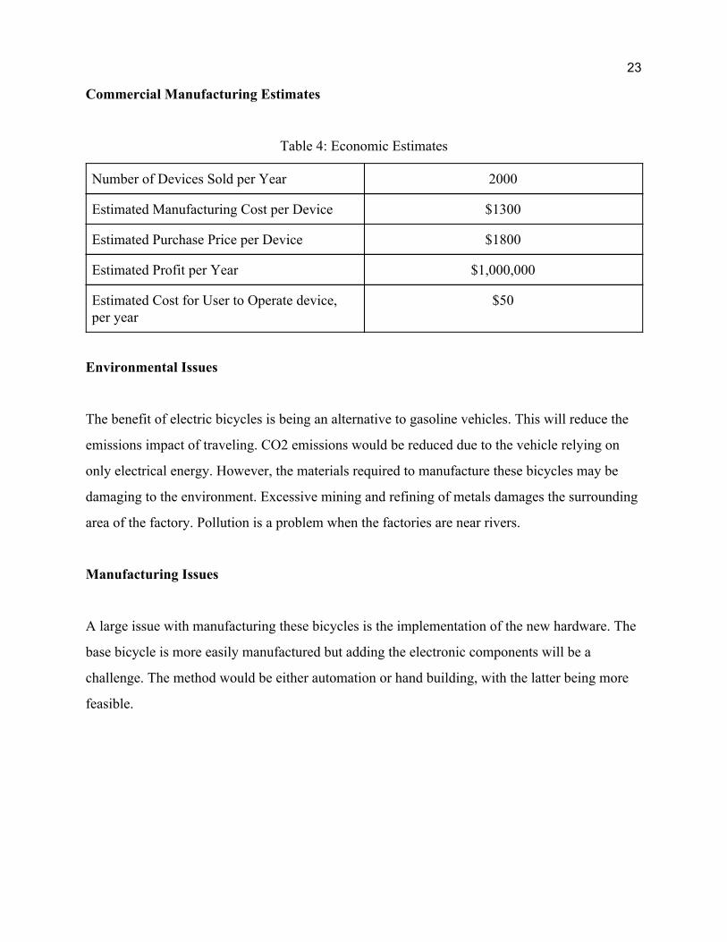
Commercial Manufacturing Estimates
Table 4: Economic Estimates
Number of Devices Sold per Year 2000
Estimated Manufacturing Cost per Device $1300
Estimated Purchase Price per Device $1800
Estimated Profit per Year $1,000,000
Estimated Cost for User to Operate device, per year
$50
Environmental Issues
The benefit of electric bicycles is being an alternative to gasoline vehicles. This will reduce the
emissions impact of traveling. CO2 emissions would be reduced due to the vehicle relying on
only electrical energy. However, the materials required to manufacture these bicycles may be
damaging to the environment. Excessive mining and refining of metals damages the surrounding
area of the factory. Pollution is a problem when the factories are near rivers.
Manufacturing Issues
A large issue with manufacturing these bicycles is the implementation of the new hardware. The
base bicycle is more easily manufactured but adding the electronic components will be a
challenge. The method would be either automation or hand building, with the latter being more
feasible.

24
Sustainability
Being a complex system of metal, rubber, and circuitry will limit the sustainability of this
product. Maintenance of the bicycle will create waste in electronics and metal. To help with this,
recycling programs would be able to recycle this waste. Upgrades to the current design would be
using recycled material to construct the bicycle. The recycled materials would depend on the
manufacturer’s use of materials in building bicycles however.
Ethics
Having electrical components on top of a mechanical bicycle leaves an extra layer of trust
between the user and the machine. The user would need to trust that the bicycle operates as
stated and is built as specified. The batteries on bicycles have substantial charge in that
sabotaging it will be a danger to the user. In order to fight against this, there will be multiple
safety mechanisms and protections for the bicycle. There will also be mechanical safeties as
well, such as brake pads. In case of bicycle theft, it is recommended to use bicycle locks for
protection.
Health and Safety
The hazards with using this product is the same as using a motorized bicycle. Vehicular safety is
an issue. A bicycle does not have the same safety features as a 5 seat car, so the user must be
careful when operating an electric bicycle. The user should not operate the vehicle when under
influence. Tampering with the bicycle may lead to injury.
25
Social and Political Issues
This project will be a publicly demonstrated product. The components used is easily identifiable
so the manufacturing choices may determine the fault for when a component fails. For example,
the supercapacitor manufacturer may take some blame if they created a faulty capacitor. Overall
however, the blame would first fall on the ones who sell the finished product. The stakeholders
would have economic benefits from selling their products but will also be taken accountable for
faults in manufacturing. It is the job of the final set of checkups before sale to ensure the
reliability of the product.
Development
The mechanical design of the system made use of the frame of the bike. Capacitor tubes are
attached to both the top and bottom frame bars and the motor controller, arduino, and relay are
attached on the rack mount behind the passenger seat. The thumb and twist grip throttles are
attached to the left handlebar for ease of access and use.
The capacitor balancing system made use of the ALD810023 and ALD910023
supercapacitor auto balancing MOSFET array. Each SAB MOSFET features a precision gate
threshold voltage in the Vt mode which is 2.3V when the gate-drain source terminals are
connected together at a drain-source current of 1uA. This design also implemented the use of two
springs at either end of the tube, forcing the capacitor contacts together.