Embed Size (px)
Citation preview
R. B. Darling EE-331 Laboratory Handbook Page 1

Organization, Hardware and Policies
R. B. Darling EE-331 Laboratory Handbook Page 2
page
I. Organization, Hardware and Policies
1. Introduction 5
2. Calendar for the Quarter 6
3. Location and Time Slots 7
4. Laboratory Groups 7
5. Laboratory Grading 8
6. Electronic Instrumentation 9
7. Parts Kits 16
8. Replacement Parts 19
9. Laboratory Notebooks 19
10. How to Use the Experimental Procedures 20
11. Errata, Improvements, and Acknowledgements 21
II. The Experiments
0. Laboratory Preliminaries and Data Acquisition using LabVIEW (E0)
P1. Transformer voltages E0.3
P2. Internal resistance of the lab transformer E0.5
P3. Create a curve tracer with your oscilloscope! E0.7
P4. Oscilloscope input resistance E0.9
P5. When is a wire not a wire? E0.10
P6. Temperature measurement using LabVIEW and DAQ hardwareE0.12
P7. Adding a Celsius to Fahrenheit conversion E0.17
P8. Saving the measurement results to spreadsheet files E0.18
1. 2-Terminal Device Characteristics and Diode Characterization (E1)
P1. Measurement of diode reverse leakage current E1.2
P2. Measurement of diode forward turn-on voltage E1.4
P3. Measurement of diode I-V characteristics using the oscilloscopeE1.6
P4. Effect of series and parallel resistances E1.9
P5. Measurement of diode I-V characteristics using LabVIEW E1.11
P6. Measurement of a zener diode E1.16
P7. Characterization of a light-emitting diode (LED) E1.17
P8. Characterization of a photoconductive cell E1.18
P9. Diode switching transients E1.19
2. Diode Circuit Applications (E2)
P1. Voltage clipper circuits E2.1
P2. Voltage limiter circuits E2.4
P3. Precision half-wave rectifier E2.6
P4. Half-wave rectifier and capacitive filtering E2.7
P5. Full-wave bridge rectifier and capacitive filtering E2.9

Organization, Hardware and Policies
R. B. Darling EE-331 Laboratory Handbook Page 3
P6. Zener diode voltage regulator E2.11
P7. Voltage clamper circuits E2.13
P8. Voltage multiplier circuits E2.14
3. JFET and MOSFET Characterization (E3)
P1. Discrete MOSFET lead, sex, and mode identification E3.3
P2. Integrated MOSFET lead, sex, and mode identification E3.7
P3. Measurement of a MOSFET using a LabVIEW curve tracer E3.10
P4. Measurement of CMOS pairs using a LabVIEW curve tracer E3.15
P5. Output conductance effects E3.18
P6. JFET gate lead, sex, and mode identification E3.19
P7. Measurement of a JFET using a LabVIEW curve tracer E3.20
P8. JFET variable attenuator E3.22
4. FET Driver, Load, and Switch Circuits (E4)
P1. E-mode MOSFET driver with resistor load E4.3
P2. E-mode MOSFET driver with D-mode load device E4.6
P3. D-mode JFET driver with resistor load E4.7
P4. CMOS inverter circuit E4.8
P5. CMOS Schmitt trigger circuit E4.9
P6. Create a VTC curve tracer using LabVIEW and DAQ hardwareE4.11
P7. CMOS inverter VTC measured using a LabVIEW curve tracerE4.17
P8. 3-input CMOS NAND gate E4.19
P9. CMOS analog switch characteristics E4.20
P10. CMOS analog switch logic circuits E4.23
P11. Flying capacitor voltage inverter E4.25
P12. Voltage step-up switch-mode power supply E4.27
P13. Sample and hold gate E4.29
5. CMOS Timing, Logic, and Memory Circuits (E5)
P1. NAND and NOR gate truth table verification E5.2
P2. Manual combinatorial logic analyzer using LabVIEW E5.6
P3. Automatic combinatorial logic analyzer using LabVIEW E5.9
P4. Non-latching monostable circuit E5.12
P5. Latching monostable circuit E5.14
P6. CMOS square wave oscillator E5.16
P7. Logic function implementation design E5.18
P8. Hardwired D-type flip-flop E5.19
P9. Asynchronous frequency divider circuits E5.20
P10. Synchronous finite state machine E5.22
P11. Push-on/push-off circuit E5.25
P12. CMOS ring oscillator E5.27
III. The Design Project: Information and Guidelines (D1)

Organization, Hardware and Policies
R. B. Darling EE-331 Laboratory Handbook Page 4
1. Overview of Electronic Circuit Design D1.1
2. Design Project Guidelines D1.3
3. Design Project Documentation D1.4

Organization, Hardware and Policies
R. B. Darling EE-331 Laboratory Handbook Page 5
Introduction
Purpose Skill in electronic circuit design is based mostly upon one's intuition about the
manner in which electronic devices operate, and upon how they interact when
interconnected in a circuit. Contrary to popular belief, the entire process of
engineering design does not take place behind the screen of a computer. The
computer is only a tool which is used to manage mundane bookkeeping chores
and to eliminate the most obvious errors. All of the computer-aided design
(CAD) software packages presently in existence only provide bookkeeping
assistance and do not eliminate the need for creativity from the designer. This
creativity must come from one's intuition. Thus, the primary purpose of this
laboratory is to start the process of training one's intuition about electronic
circuits.
Skills In addition, laboratory experience is necessary for building certain skills that
are needed in electrical engineering. These skills include the proper and
knowledgeable use of electronic instrumentation, the ability to prototype
designs, the ability to make certain routine measurements, and perhaps most
importantly, the ability to troubleshoot and correct problems in designs which
did not work as planned. These skills, like the creative spark itself, are not
obtained from rote mathematical analysis of the theory, nor do they come from
hours of flagelation with computer software. These skills and creativity
instead come from “hands-on” interaction with the subject matter in question,
which is of course what the laboratory provides.
Hacking The usefulness of the laboratory will be enhanced if a hacking attitude is
adopted. By this is meant an open-minded attitude of liberally trying out new
thoughts without a lot of mathematical analysis, library reference, or computer
simulation. Learn to make solder your programming language! Learn not to
trust any schematic until you see it working properly in front of you! Learn to
distrust SPICE! Learn to not trust that you have the correct wire in your hand
until you have traced back to find where the other end is going. Electronic
component parts are for the most part cheap and easily replaceable. Don’t be
afraid to push them to their limits or blow a few up in the quest for your new
design.

Organization, Hardware and Policies
R. B. Darling EE-331 Laboratory Handbook Page 6
Calendar for the Quarter
Overview The laboratories are intended to occur on a regular cycle of once per week
over the 10 weeks of the quarter. There is no laboratory activity the first
week. Laboratory work begins on a normal schedule starting the second week,
with a first meeting to get acquainted with the teaching assistant and to
perform some “warm-up” procedures with the lab equipment. After the 5
main laboratory experiments have been completed, the remainder of the
quarter is reserved for development of the design project. It is expected that
the design project should not carry over into finals week.
Week-1 No laboratory meeting
Week-2 Experiment-0 and introduction to the lab and the TA
Week-3 Experiment-1
Week-4 Experiment-2
Week-5 Experiment-3
Week-6 Experiment-4
Week-7 Experiment-5
Week-8 Open lab time for design project
Week-9 Open lab time for design project
Week-10 Open lab time for design project
Week-11 Finals Week: all labs should be completed before this
Reminders
My TA is
My Lab Section is
My Lab Time Slot is
My Lab Partners are
Organization, Hardware and Policies
R. B. Darling EE-331 Laboratory Handbook Page 7
Location and Time Slots
Location The laboratory will be held in Room 137 of the EE1 (EE/CSE) Building.
Time Slots Each laboratory section is allocated one 3-hour block of time per week. Due
to the heavy use of the Room 137 laboratory by other sections, and by other
classes as well, it is not possible to schedule time other than the pre-arranged
weekly slot.
In order to get the most out of your laboratory time, you should read through
the experimental procedures ahead of time to familiarize yourself with what
needs to be done. Some of the experiments require a good deal of set-up, and
you will need to move through the procedures expediently in order to finish
them all.
Laboratory Groups
Groups The overall EE-331 class is divided into laboratory sections of nominally 24
students each. The resources presently available in the Room 137 laboratory
only provide 8 complete test benches. Therefore, the students of each
laboratory section must work in 8 groups of 3 members each. Because of the
limited availability of equipment, this group size must remain fixed.
Teamwork It is rare in modern engineering for engineers to work completely by
themselves. In order to see a project through to its completion, an engineer
must interface with other engineers, managers, and technicians. It is a good
idea to start now (in this laboratory) in applying the basic ideas of working
within a group or team. These ideas include dividing up the tasks among team
members, managing the tasks so that they all are finished in concert with one
another, and most importantly, getting along peacefully with the rest of the
team throughout the process.
Who Does What In small groups of 3 members, it is important for everyone to participate
equally. The situation where one person does all of the work and the others
simply stand around and watch should be avoided at all cost. Your group
should set up some method to rotate around between members who are
recording data, manipulating the instruments, reading instructions, or
constructing or modifying the breadboards.

Organization, Hardware and Policies
R. B. Darling EE-331 Laboratory Handbook Page 8
Laboratory Grading
Experiments Each of the 5 experiments are weighted equally and are graded completely
from the write-up in the laboratory notebook. Experiment-0 is not graded.
The T.A. will only grade that part of the lab notebook which pertains to the
“Question-X” part which is asked within a given procedure. The rest of the
notebook entries are for your use. Consequently, you should put the answers
to the asked questions inside a highlighted box in your notebook so that the
T.A. can more easily find them. This is described later on in this handbook.
Each student of the group must submit a laboratory notebook, and the scores
are assigned individually, not to the group as a whole.
Design Project The design project, which occupies the last 3 weeks of the laboratory, will
involve a combined effort from the group as a whole. Each group will submit
one set of design documents (described later) and will demonstrate one
working version of their circuit. The score received on the design project will
be composed from the design documentation (50 percent) and from how well
the actual prototyped circuit performs, as demonstrated to the T.A. (50
percent). Each member of the group will receive the same score for the design
project.
Lab Grade The lab grade will be composed from the score on the experiment write-ups in
the lab notebook (60 percent) and from the score on the design project (40
percent). Even though the laboratory provides only 1 credit hour out of the 5
credits for the class, the laboratory grade will count 30 percent toward your
final class grade to emphasize its importance.
Organization, Hardware and Policies
R. B. Darling EE-331 Laboratory Handbook Page 9
Electronic Instrumentation
Quality Electronic instrumentation is becoming increasingly more sophisticated each
year. The laboratory in Room 137 is fortunate to have most of its equipment
donated from Hewlett-Packard (now Agilent,), Tektronix, Fluke, and National
Instruments. The generosity of these companies has created a laboratory
which is far superior to that which would have been possible with Washington
State funds alone. This equipment is generally state-of-the-art, and what one
should expect to find in a well-equiped electronics laboratory of a future
employer.
Operation Each piece of equipment has many different operational modes, features, and
functions, and to learn how to use all of these could take several days for each
instrument. Nevertheless, there are some basic operations on each instrument
that you should learn as quickly as possible. Presumably, some of the more
basic operational procedures have already been encountered in previous EE
laboratory courses. It is highly recommended to spend some time during the
first lab meeting (week 2; see calendar) to familiarize yourself with the given
instruments and how to configure them for their most basic functions.
Configuring Setting up an instrument to perform a given function is termed configuring the
instrument. In the laboratory procedures, you will be instructed to configure
certain instruments to produce a given function, for example, “configure a
DMM to measure voltage at the output node of the circuit.” From this, you
must be able to properly connect the test leads and program the instrument
from its front panel to produce this function. Since the specific instruments
may vary from bench to bench, you will not be given any specific instructions
for the instruments.
Handling Each piece of electronic instrumentation in the Room 137 laboratory is a
precision instrument, and each should be treated as such. It is very important
to think through what you are doing and consider the consequences before you
actually start the procedure. Unlike software manipulation, where one can
freely hack away without regard to consequence, playing around with real
voltages and currents can lead to serious damage, either to the test circuit
components, the instrument itself, or occasionally to the operator. This is
particularly true with signal generators and power supplies.
Problems One fact of life is that equipment breaks from time to time. If you think that
your particular instrument is not working properly, first contact the TA. Do
not try to fix any equipment yourselves. Also, do not move equipment from
bench to bench without first consulting the TA.

Organization, Hardware and Policies
R. B. Darling EE-331 Laboratory Handbook Page 10
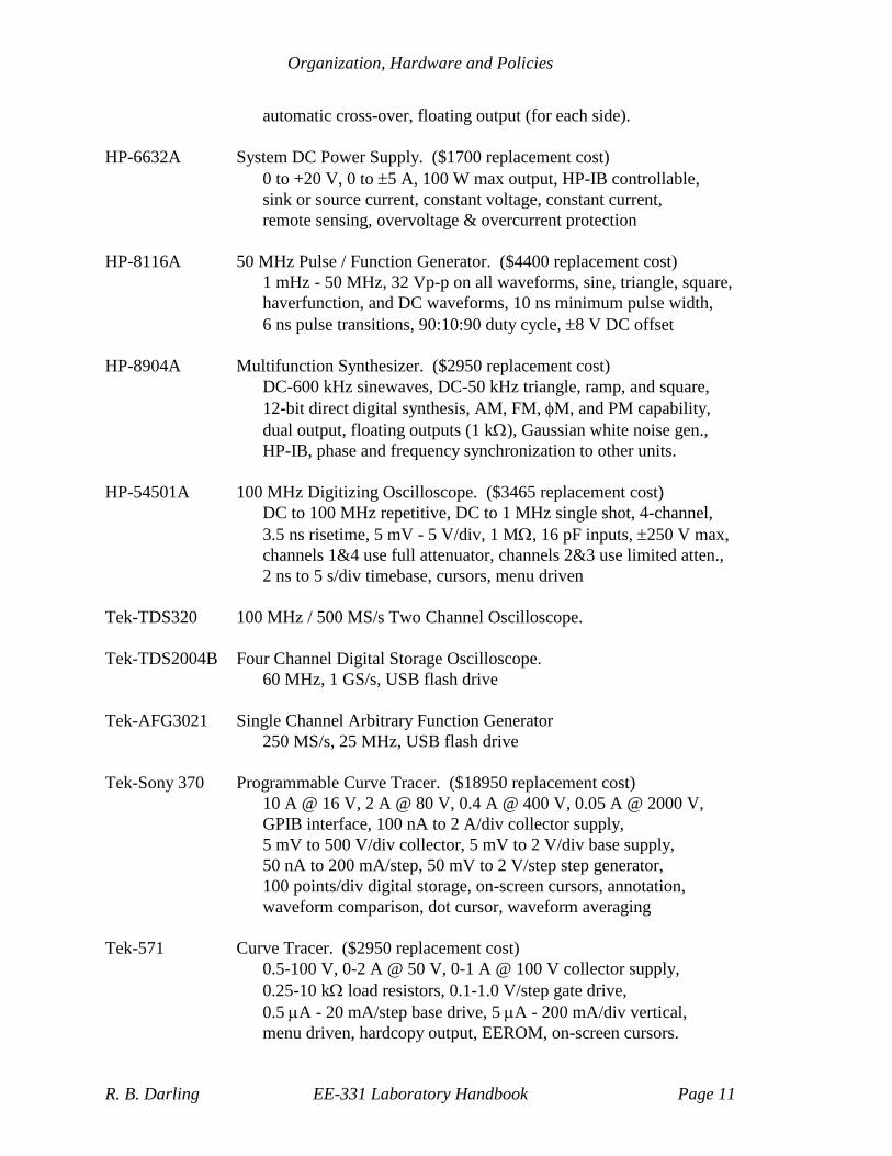
Specifications For purposes of perspective, listed below are some of the advertised
specifications on the various pieces of instrumentation available in the
Electrical Engineering Department laboratories, both past and present.
HP-3114A Function Generator. ($4800 replacement cost)
Lin/log sweep, gate, counted burst, AM/FM/VCO, HP-IB,
1/2 cycle mode, arbitrary waveform gen., phase lock N, N,
sine, square, and triangle 1mHz - 20 MHz, 0-10 Vpp into 50 ,
pulses and ramps to 2 MHz with 5-95 % symmetry.
HP-3312A Function Generator. ($1600 replacement cost)
0.1 Hz - 13 MHz, sine, triangle, ramp, pulse, AM, FM, sweep,
triggered, and gated, 80:20:80 % symmetry, 50 outputs,
20 Vpp into open circuit, 10 V DC offset, <20 ns pulse edges
HP-33120A 15 MHz Function / Arbitrary Waveform Generator. ($1725 cost)
Sine, square, triangle, and ramp waveforms, AM, FM, FSK, and
burst modulation, linear and log sweeps, 80:20:80 symmetry,
12 bit 16k arbitrary waveform generator @ 40 MS/s
HP-3478A Digital Multimeter. ($995 replacement cost)
3-1/2 to 5-1/2 digit accuracy, 100 nV resolution, true rms,
4-wire ohmmeter, HP-IB, electronic calibration, 90 readings/sec,
300 kHz bandwidth, 4:1 crest factor, autoranging.
HP-34401A Digital Multimeter.
HP-3562A Dynamic Signal Analyzer. No longer manufactured.
100 kHz FFT analyzer, 2 channel, internal source and noise source
HP-3582A Spectrum Analyzer. No longer manufactured.
20 kHz FFT analyzer, 2 channel, internal source and noise source
Tek-2711 Spectrum Analyzer.
9 kHz – 1.8 GHz, 50 Ω input
Agilent-E3630A Triple Output DC Power Supply.
0 to +6 V @ 2.5 A, 0 to +20 V @ 0.5 A, and 0 to −20 V @ 0.5 A,
HP-6236B Triple Output Power Supply. ($900 replacement cost)
0 to +6 V @ 2.5 A, 0 to +20 V @ 0.5 A, and 0 to −20 V @ 0.5 A,
35 W total, constant voltage with current limit, dual tracking
HP-6255A Dual DC Power Supply. ($1900 replacement cost)
0-40 V, 0-1.5 A, 0-60 W, constant voltage/constant current modes,
Organization, Hardware and Policies
R. B. Darling EE-331 Laboratory Handbook Page 11
automatic cross-over, floating output (for each side).
HP-6632A System DC Power Supply. ($1700 replacement cost)
0 to +20 V, 0 to 5 A, 100 W max output, HP-IB controllable,
sink or source current, constant voltage, constant current,
remote sensing, overvoltage & overcurrent protection
HP-8116A 50 MHz Pulse / Function Generator. ($4400 replacement cost)
1 mHz - 50 MHz, 32 Vp-p on all waveforms, sine, triangle, square,
haverfunction, and DC waveforms, 10 ns minimum pulse width,
6 ns pulse transitions, 90:10:90 duty cycle, 8 V DC offset
HP-8904A Multifunction Synthesizer. ($2950 replacement cost)
DC-600 kHz sinewaves, DC-50 kHz triangle, ramp, and square,
12-bit direct digital synthesis, AM, FM, M, and PM capability,
dual output, floating outputs (1 k), Gaussian white noise gen.,
HP-IB, phase and frequency synchronization to other units.
HP-54501A 100 MHz Digitizing Oscilloscope. ($3465 replacement cost)
DC to 100 MHz repetitive, DC to 1 MHz single shot, 4-channel,
3.5 ns risetime, 5 mV - 5 V/div, 1 M, 16 pF inputs, 250 V max,
channels 1&4 use full attenuator, channels 2&3 use limited atten.,
2 ns to 5 s/div timebase, cursors, menu driven
Tek-TDS320 100 MHz / 500 MS/s Two Channel Oscilloscope.
Tek-TDS2004B Four Channel Digital Storage Oscilloscope.
60 MHz, 1 GS/s, USB flash drive
Tek-AFG3021 Single Channel Arbitrary Function Generator
250 MS/s, 25 MHz, USB flash drive
Tek-Sony 370 Programmable Curve Tracer. ($18950 replacement cost)
10 A @ 16 V, 2 A @ 80 V, 0.4 A @ 400 V, 0.05 A @ 2000 V,
GPIB interface, 100 nA to 2 A/div collector supply,
5 mV to 500 V/div collector, 5 mV to 2 V/div base supply,
50 nA to 200 mA/step, 50 mV to 2 V/step step generator,
100 points/div digital storage, on-screen cursors, annotation,
waveform comparison, dot cursor, waveform averaging
Tek-571 Curve Tracer. ($2950 replacement cost)
0.5-100 V, 0-2 A @ 50 V, 0-1 A @ 100 V collector supply,
0.25-10 k load resistors, 0.1-1.0 V/step gate drive,
0.5 A - 20 mA/step base drive, 5 A - 200 mA/div vertical,
menu driven, hardcopy output, EEROM, on-screen cursors.
Organization, Hardware and Policies
R. B. Darling EE-331 Laboratory Handbook Page 12
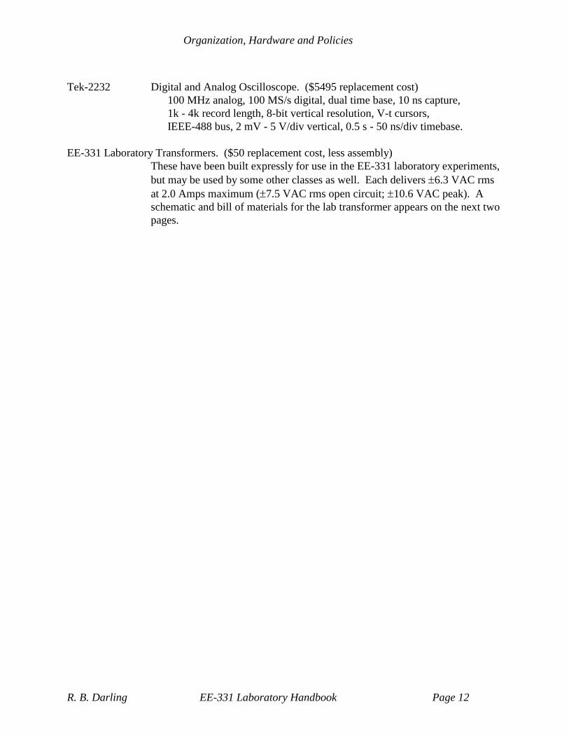
Tek-2232 Digital and Analog Oscilloscope. ($5495 replacement cost)
100 MHz analog, 100 MS/s digital, dual time base, 10 ns capture,
1k - 4k record length, 8-bit vertical resolution, V-t cursors,
IEEE-488 bus, 2 mV - 5 V/div vertical, 0.5 s - 50 ns/div timebase.
EE-331 Laboratory Transformers. ($50 replacement cost, less assembly)
These have been built expressly for use in the EE-331 laboratory experiments,
but may be used by some other classes as well. Each delivers 6.3 VAC rms
at 2.0 Amps maximum (7.5 VAC rms open circuit; 10.6 VAC peak). A
schematic and bill of materials for the lab transformer appears on the next two
pages.

Organization, Hardware and Policies
R. B. Darling EE-331 Laboratory Handbook Page 13
EE-331 Laboratory Transformer Schematic:
T1
P-8130Stancor
S1
MTA-106DALCOSwitch
F1
3AG 0.5Ampslow blow3453-LF1
fuseholder
F2
3AG 2Ampfast acting
3453-LF1fuseholder
F3
3AG 2Ampfast acting
3453-LF1fuseholder
J1
111-0103-001Johnson
(black)
1
J2
111-0101-001Johnson
(white)
1
J3
111-0102-001Johnson
(red)
1
J4
111-0104-001Johnson
(g reen)
1
P1
Belden 17406BNEMA 5-15P
18AWG power cord
120 VAC
+6.3 VAC
Neutral
-6.3 VAC
Ground
HOT
GROUND
NEUTRAL
Output = +/- 7.5 Vrms @ open circuit
Output = +/- 6.3 Vrms @ 2.0 Amps
4"x5"x3" gray aluminum cabinet
Bud AU-1028
screw terminal/banana socketson std. 0.75" spacing
(black)
(g reen)
(white)
SAFETY
LXFMR331 1A
EE-331 Lab Transformer
Robert B. Darling
Device Electronics LaboratoryDepartment of Electrical Engineering, Box 352500University of WashingtonSeattle, Washington 98195 U.S.A.
A
1 1Friday, March 17, 2000
Title
Size Document Number Rev
Date: Sheet of

Organization, Hardware and Policies
R. B. Darling EE-331 Laboratory Handbook Page 14
EE-331 Laboratory Transformer Bill of Materials:
Bill of Materials
EE-331 Lab Transformer
Design # LXFMR331-Rev. A1R.B.Darling, 1993/6/5
Identifier Manufacturer Part Number Description Quantity Price Each Subtotal
T1 Stancor P-8130 120VAC:12.6 CT@2A, 25VA 1 $11.25 $11.25
power transformer
S1 ALCOSwitch MTA-106D SPDT 120V@6A switch 1 $3.60 $3.60
F1 Littelfuse 3AG 0.5 A slow blow fuse 1 $0.87 $0.87
F2,F3 Littelfuse 3AG 2.0 A fast acting fuse 2 $0.25 $0.50
P1 Belden 17406B black PVC NEMA 5-15P 1 $5.39 $5.39
three-wire power cord
J1 Johnson 111-0103-001 black banana/screw jack 1 $1.44 $1.44
J2 Johnson 111-0101-001 white banana/screw jack 1 $1.44 $1.44
J3 Johnson 111-0102-001 red banana/screw jack 1 $1.44 $1.44
J4 Johnson 111-0104-001 green banana/screw jack 1 $1.44 $1.44
Littelfuse 3453-LF1 3AG fuse holder 3 $1.72 $5.16
Bud AU-1028 4"x5"x3" aluminum cabinet 1 $12.80 $12.80
Subtotal for each unit: $45.33
8.2 % sales tax $3.72
Subtotal with tax: $49.05
Total for EE-331 labs: 12 $49.05 $588.56

Organization, Hardware and Policies
R. B. Darling EE-331 Laboratory Handbook Page 15
List of Equipment Needed for each of the Experiments
Experiment-0 Laboratory Preliminaries
digital multimeter
EE-331 6.3 VAC laboratory transformer
oscilloscope
DC power supply
Computer running LabVIEW
NI-USB-6009 DAQ and USB cable
Experiment-1 2-Terminal Device Characteristics and Diode Characterization
digital multimeter
EE-331 6.3 VAC laboratory transformer
oscilloscope
DC power supply
Computer running LabVIEW
NI-USB-6009 DAQ and USB cable
Experiment-2 Diode Circuit Applications
EE-331 6.3 VAC laboratory transformer
DC power supply
oscilloscope
digital multimeter
Experiment-3 JFET and MOSFET Characterization
digital multimeter
DC power supply
Computer running LabVIEW
NI-USB-6009 DAQ and USB cable
Experiment-4 FET Driver, Load, and Switch Circuits
DC power supply
digital multimeter
function generator
oscilloscope
NI-USB-6009 DAQ and USB cable
Experiment-5 CMOS Timing, Logic, and Memory Circuits
DC power supply
function generator
oscilloscope
NI-USB-6009 DAQ and USB cable

Organization, Hardware and Policies
R. B. Darling EE-331 Laboratory Handbook Page 16
Parts Kits
Purchase Each laboratory group must purchase one standard kit of parts for the EE-331
laboratory experiments. This kit contains all of the necessary parts which will
be used in the five experiments. The parts kit is not intended to supply all of
the parts which may be needed in the design project; these are an additional
purchase. The parts kits may be purchased from the E.E. Stores, room 147 of
the EE1 building. Parts can be purchased through the E.E. Stores window
which opens into the room 137 laboratory. It is suggested that the members of
the laboratory group divide up the cost of the parts between themselves.
Contents The standard-issue EE-331 parts kit should contain the following:
Quantity Industry
Part Number
Description EE Stores
Part Number
EE Stores
Price (Each)
1 Resistor, 100 Ω, 1/4 W, 5% RBD0-100
1 Resistor, 470 Ω, 1/4 W, 5% RBD0-470
3 Resistor, 1.0 kΩ, 1/4 W, 5% RBD3-1.0
1 Resistor, 4.7 kΩ, 1/4 W, 5% RBD3-4.7
7 Resistor, 10 kΩ, 1/4 W, 5% RBD3-10
1 Resistor, 20 kΩ, 1/4 W, 5% RBD3-20
1 Resistor, 33 kΩ, 1/4 W, 5% RBD3-33
3 Resistor, 100 kΩ, 1/4 W, 5% RBD3-100
1 Resistor, 220 kΩ, 1/4 W, 5% RBD3-220
1 Resistor, 1.0 MΩ, 1/4 W, 5% RBD6-1.0
2 Resistor, 10 MΩ, 1/4 W, 5% RBD6-10
1 Resistor, 100 Ω, 1/4 W, 1% RCD0-100
3 Resistor, 1.0 kΩ, 1/4 W, 1% RCD3-1.0
6 Resistor, 10 kΩ, 1/4 W, 1% RCD3-10
3 Resistor, 100 kΩ, 1/4 W, 1% RCD3-100
1 Resistor, 1.0 MΩ, 1/4 W, 1% RCD6-1.0
1 Potentiometer, 10 kΩ, 1 turn T34-103
1 Potentiometer, 100 kΩ, 1 turn T34-104
4 Capacitor, 33 pF, ceramic disk CC0-33
4 Capacitor, 220 pF, ceramic disk CC1-22
4 Capacitor, 0.001 F, ceramic disk CC2-10
1 Capacitor, 0.047 F, ceramic disk CC3-47
6 Capacitor, 0.1 F, ceramic disk CC4-10
6 Capacitor, 10 F, 25 V, electrolytic CE6-10
1 Capacitor, 33 F, 25 V, electrolytic CE6-33.25
1 Inductor, 100 mH I4-10
2 1N34A Diode, Germanium 1N34A
2 1N4148 Diode, Silicon, high speed switching 1N4148
6 1N4007 Diode, Silicon, rectifier, 1000 V, 1 A 1N4007
3 1N4732 Diode, Zener, 4.7 V 1N4732
2 1N4744 Diode, Zener, 15 V 1N4744
2 1N5819 Diode, Silicon Schottky, 40 V, 1 A 1N5819
1 HT-32 Diac, Silicon, 27-32 V HT-32
4 LN28RP
(Panasonic)
LED, red, GaAsP, T1-3/4 (5 mm), 700 nm,
0.8 mcd @ 15 mA, 2 V
LN28RP

Organization, Hardware and Policies
R. B. Darling EE-331 Laboratory Handbook Page 17
1 VT-301
(EG&G VacTec)
Photoconductive cell, CdSe VT-301
2 MPF102 JFET, n-channel, D-mode MPF102
1 2N7000 MOSFET, n-channel, E-mode, 60 V 2N7000
1 CD4001 IC, quad 2-input NOR gate CD4001
1 CD4007 IC, CMOS array CD4007
1 CD4011 IC, quad 2-input NAND gate CD4011
2 CD4013 IC, dual D-type flip-flop CD4013
1 CD4016 IC, quad analog switch CD4016
1 MC1458 IC, dual operational amplifier MC1458
1 LM35DZ IC, Centigrade temperature sensor LM35DZ
1 Potentiometer trimming tool
1 Spool of #22 AWG solid hook up wire
1 Plastic compartmented box

Organization, Hardware and Policies
R. B. Darling EE-331 Laboratory Handbook Page 18
Breadboards At least one superstrip (solderless breadboard) will be required for the
laboratory. If you already have one of these from a previous laboratory, there
is no need to buy a second one. The E.E. Stores will sell parts kits either with,
or without, the superstrip breadboards.
The $10.00 superstrip uses 770 alloy contacts which is generally satisfactory
for all purposes in this lab. Those with wealthy parents may wish to flaunt
their social status and buy the gold-plated contact version for about $35.00.
These are available to the gullible at many of the local electronics parts stores.
Test Leads The laboratory in Room 137 only maintains the following test leads for each
bench:
Two 10 oscilloscope probes
Two BNC(m)-to-BNC(m) coaxial cables
Two BNC(f)-to-dual alligator clip leads
Assorted banana plug(m)-to-banana plug(m) jumpers
Many of these test leads have a tendency to wander from their proper point of
use. To help reduce your irritation level, you are strongly suggested to buy
and maintain your own set of test leads. These can be either made up yourself,
or purchased from the stockroom.
The premier version consists of a male banana plug on one end and a squeeze-
hook on the other. A less expensive version is to make a set of leads from #22
AWG solid wire and put a banana plug on one end. Simply stripping off 1/4"
of insulation from the other end will provide a connection that can be plugged
into the tie points on the solderless breadboards. Cheaper still (but least
convenient) is to just use #22 AWG solid wire and attach the end that would
have the banana plug to the banana jack on the instruments (when possible).
Handling Parts The CMOS integrated circuits and the discrete MOSFET's are static sensitive
devices which are quite easily destroyed by careless handling. The discrete
MOSFET's in particular are extremely sensitive because they do not contain
any internal protection diodes. All of these parts should be stored on the black
conductive foam until they are needed. Make sure that you are grounded
when you remove any of these parts from the foam, so as to avoid possible
electrostatic discharge (ESD) damage. Also, make certain that your circuits
are connected properly before applying power to them.

Organization, Hardware and Policies
R. B. Darling EE-331 Laboratory Handbook Page 19
Replacement Parts
Kablooey! You are responsible for replacing any parts that you blow out as a result of
either static or improper circuit connections. The E.E. Stores is not
responsible for ensuring that you have working parts. In addition, they will
not accept back used parts for a refund. Static sensitive CMOS devices are a
fact of modern electronics. Part of the purpose of this laboratory is to train
you in how to successfully handle and employ these devices.
Laboratory Notebooks
Notetaking 60 percent of the laboratory grade is derived from the laboratory notebook.
This notebook is intended to look and function as a running scratchpad for
your experimental lab work. It does not have to be particularly pretty, but it
does need to be legible enough for the T.A. to make sense out of it.
Laboratory notebooks are not designed to be taken home and recopied; you
should learn to write clearly and legibly on the fly. In the long term, this will
save you a lot of time.
What to Include In general, you should include anything that you want to remind yourself about
in the future. These can be calculations, instrument settings and/or unusual
characteristics, measurement results, circuit schematics, or specific
conclusions from the experiments.
What to Highlight For purposes of grading, the T.A. will only be looking for answers to each of
the “Question-X” sections, which appear within each of the experimental
procedures. The remainder of the lab notebook is for your own use and will
not count for or against your notebook grade. As a result, you should put a
colored or highlighted box around each place in you notebook which responds
to the “Question-X” section so that the T.A. can more easily locate it. In
general, if it is not highlighted or circled with an obvious box, the T.A. is
under no obligation to count it.
Two Notebooks In general, the T.A. will attempt to grade and return each experiment within 2
weeks or so. However, the labs run each week, so there exists a problem in
getting the graded lab notebook back to each student in time for the next lab
session. To fix this problem, it is suggested that you use two notebooks, and
alternate lab experiments between them. This way, the T.A. can be grading
one notebook while you are working with the other.
Organization, Hardware and Policies
R. B. Darling EE-331 Laboratory Handbook Page 20
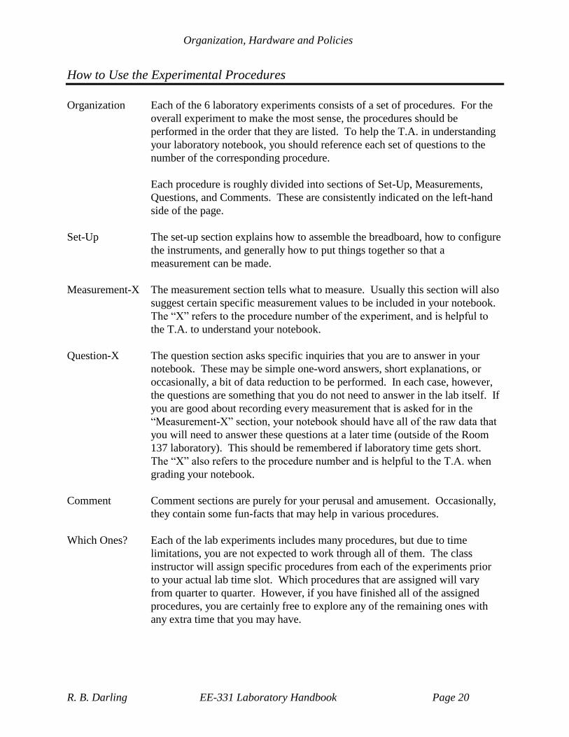
How to Use the Experimental Procedures
Organization Each of the 6 laboratory experiments consists of a set of procedures. For the
overall experiment to make the most sense, the procedures should be
performed in the order that they are listed. To help the T.A. in understanding
your laboratory notebook, you should reference each set of questions to the
number of the corresponding procedure.
Each procedure is roughly divided into sections of Set-Up, Measurements,
Questions, and Comments. These are consistently indicated on the left-hand
side of the page.
Set-Up The set-up section explains how to assemble the breadboard, how to configure
the instruments, and generally how to put things together so that a
measurement can be made.
Measurement-X The measurement section tells what to measure. Usually this section will also
suggest certain specific measurement values to be included in your notebook.
The “X” refers to the procedure number of the experiment, and is helpful to
the T.A. to understand your notebook.
Question-X The question section asks specific inquiries that you are to answer in your
notebook. These may be simple one-word answers, short explanations, or
occasionally, a bit of data reduction to be performed. In each case, however,
the questions are something that you do not need to answer in the lab itself. If
you are good about recording every measurement that is asked for in the
“Measurement-X” section, your notebook should have all of the raw data that
you will need to answer these questions at a later time (outside of the Room
137 laboratory). This should be remembered if laboratory time gets short.
The “X” also refers to the procedure number and is helpful to the T.A. when
grading your notebook.
Comment Comment sections are purely for your perusal and amusement. Occasionally,
they contain some fun-facts that may help in various procedures.
Which Ones? Each of the lab experiments includes many procedures, but due to time
limitations, you are not expected to work through all of them. The class
instructor will assign specific procedures from each of the experiments prior
to your actual lab time slot. Which procedures that are assigned will vary
from quarter to quarter. However, if you have finished all of the assigned
procedures, you are certainly free to explore any of the remaining ones with
any extra time that you may have.

Organization, Hardware and Policies
R. B. Darling EE-331 Laboratory Handbook Page 21
Errata, Improvements, and Acknowledgements
Errata Despite best efforts, there most likely exist errors in this laboratory manual:
possibly incorrect instrument settings, schematic errors, incorrect part values,
and/or simply silly instructions. The best proofreading will undoubtedly be by
the class using this handbook, so it is YOU who should tell the author about
the mistakes. The plan is for this laboratory handbook to be regularly revised.
Please send your uncovered errors to:
Prof. R. B. Darling
Dept. of Electrical Engineering
Box 352500
University of Washington
Seattle, WA 98195-2500
or send e-mail to:
Improvements Likewise, if you have any suggestions for improvements in this laboratory
handbook, the procedures contained therein, or the laboratory itself, I welcome
your comments. Please send them to me at either of the above addresses. I
would also welcome any suggestions for new procedures to be added to the
existing set of experiments.
Thanks! The author is indebted to the many previous students of EE-331 who have
contributed their careful suggestions (and relentless complaints) as these have
helped immeasurably to make this laboratory handbook more effective.
Thanks are also extended to Dr. W. T. Dietze, who taught EE-331 during the
1996-97 academic year, and who contributed the initial versions of procedures
0.1, 0.2, 0.3, 0.4, 0.5, 2.2, 2.3, 3.7, 4.9, 4.10, and 4.11.


![Chapter 1: Diode circuits vtusolutionvtusolution.in/uploads/9/9/9/3/99939970/analog_electronic[15ec32].pdf · Chapter 1: Diode circuits ... • Diode testing • Zener diode • Diode](https://img.dokumen.tips/doc/110x75/5aedefea7f8b9a9031905d54/chapter-1-diode-circuits-vt-15ec32pdfchapter-1-diode-circuits-diode.jpg)