Embed Size (px)
Citation preview

Information for the operatorof the machine/system
EDK82MVXXX!N;,
Global Drive8200 motecFrequency inverter0.25 ... 7.5 kW
Ä!N;,ä

This documentation applies to 8200 motec inverters as of version
E82MV xxx _ x B001 XX Vx 2x
Type
Power
(e. g. 551 = 55 × 101 W = 0,55 kW)
(e. g. 752 = 75 × 102 W = 7,5 kW)
Voltage class2 = 230 V4 = 400 V/500 V
Hardware version
Software version
2002 Lenze AG
This documentation contains all information the machine operator require in orderto operate the drive controller of the 8200 motec series installed in yourmachine/system.
If you do not change the content, you are allowed to use the information in thisdocumentation for your purposes without contacting Lenze.
The information necessary for the project planning of a machine/system can be found inthe Mounting Instructions and Operating Instructions for the 8200 motec frequencyinverters. The Mounting Instructions are included in the scope of delivery, the OperatingInstructions can be ordered at your Lenze representative.
The downloading of the Lenze documentation can be made in the internet as an AdobeAcrobat file:
http://www.lenze.de
1.0 03/2002 TD14

Safety informationLenze controllers
3l EDK82MVXXX EN 1.0
1 Safety information
1.1 General safety and application notes for Lenze controllers(according to Low-Voltage Directive 73/23/EEC)
1. GeneralLenze controllers (frequency inverters, servo inverters, DC controllers) can carry a voltage or parts of the controllers can rotate during operation. Surfaces can be hot.If the required cover is removed, the controllers are used inappropriately or installed or operated incorrectly, severe damage to persons or material assets can occur.For more information please see the documentation.All operations concerning transport, installation, and commissioning as well as maintenance must be carried out by qualified, skilled personnel (IEC 364 and CENELEC HD384 or DIN VDE 0100 and IEC report 664 or DIN VDE 0110 and national regulations for the prevention of accidents must be observed).According to this basic safety information qualified, skilled personnel are persons who are familiar with the assembly, installation, commissioning, and operation of theproduct and who have the qualifications necessary for their occupation.
2. Intended useDrive controllers are components which are designed for the installation into electrical systems or machinery. They are not to be used as domestic appliances, but onlyfor industrial purposes according to EN 61000-3-2. The documentation contains information about the compliance of the limit values with EN 61000-3-2.When installing controllers into machines, commissioning of the drive controllers (i.e. the starting of operation as directed) is prohibited until it is proven that the machinecorresponds to the regulations of the EC Directive 98/37/EG (Machinery Directive); EN 60204 (VDE 0113) must be observed.Commissioning (i.e. starting of operation as directed) is only allowed when there is compliance with the EMC Directive (89/336/EEC).The drive controllers meet the requirements of the Low-Voltage Directive 73/23/EEC. The harmonised standards EN 50178/DIN VDE 0160 apply to the controllers.The technical data as well as the connection conditions can be obtained from the nameplate and the documentation. The instructions given must be strictly observed.Warning: Controllers are products with restricted availability according to EN 61800-3. These products can cause interferences in residential premises. If controllers areused in residential premises, corresponding measures are required.
3. Transport, storageThe notes on transport, storage and appropriate handling must be observed.Climatic conditions according to EN 50178 apply.
4. InstallationThe controllers must be installed and cooled according to the regulations given in the corresponding Instructions.Ensure careful handling and avoid mechanical overload. Do not bend any components and do not change the insulation distances during transport and storage. Electroniccomponents and contacts must not be touched.Controllers contain electrostatically sensitive components which can easily be damaged by inappropriate handling. Do not damage or destroy any electrical componentssince this could mean hazards for your health!
5. Electrical connectionWhen working on live controllers, the valid national regulations for the prevention of accidents (e. g. VBG 4) must be observed.The electrical installation must be carried out in compliance with the corresponding regulations (e.g. cable cross-sections, fuses, PE connection). Additional notes andinformation can be obtained from the corresponding Instructions.The Instructions contain notes concerning wiring according to EMC regulations (shielding, earthing, filters and cable routing). These notes must also be observed whenusing CE-marked controllers. The compliance with limit values required by the EMC legislation is the responsibility of the manufacturer of the machine or system.
6. OperationIf necessary, systems including controllers must be equipped with additional monitoring and protection devices according to the applying safety regulations (e.g. regulationfor technical equipment, regulation for the prevention of accidents). The controller can be adapted to your application. Please observe the corresponding information givenin the Instructions.After a controller has been disconnected from the voltage supply, all live components and power connections must not be touched immediately because capacitors canstill be charged. Please observe the corresponding stickers on the controller.All protection covers and doors must be shut during operation.Note for UL-approved systems with integrated controllers: UL warnings are notes which only apply to UL systems. The Instructions give UL-related information.
7. Safe standstillThe variant V004 of 9300 and 9300 vector, the variant Bx4x of 8200 vector controller and the axis controller ECSXA064 support the function ”Safe standstill”, protectionagainst unexpected start, according to the requirements of Annex I No. 1.2.7 of the EC Directive ”Machinery” 98/37/EG, DIN EN 954-1 category 3 and DIN EN 1037. Pleaseobserve the notes on the function ”Safe standstill” given in the corresponding Instructions.
8. Maintenance and servicePlease observe the Instructions given by the manufacturer.
Please observe the product-specific safety and application notes in these Instructions.
Safety informationLenze low-voltage machinery
4 lEDK82MVXXX EN 1.0
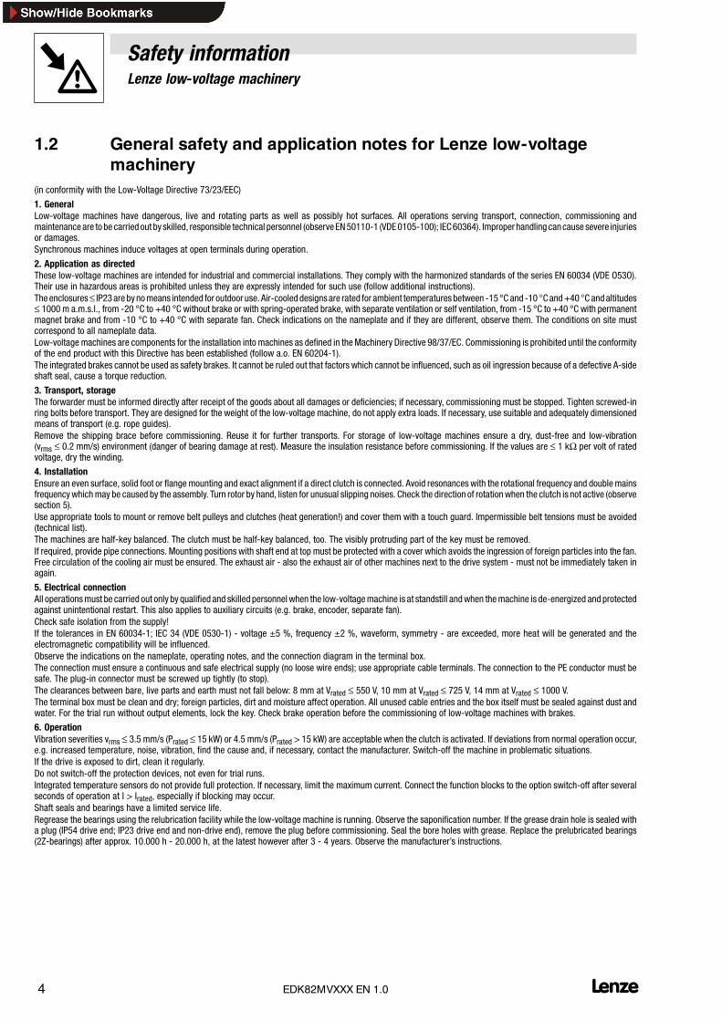
1.2 General safety and application notes for Lenze low-voltagemachinery
(in conformity with the Low-Voltage Directive 73/23/EEC)
1. GeneralLow-voltage machines have dangerous, live and rotating parts as well as possibly hot surfaces. All operations serving transport, connection, commissioning andmaintenance are to be carried out by skilled, responsible technical personnel (observe EN50110-1 (VDE0105-100); IEC60364). Improperhandling cancause severe injuriesor damages.Synchronous machines induce voltages at open terminals during operation.
2. Application as directedThese low-voltage machines are intended for industrial and commercial installations. They comply with the harmonized standards of the series EN 60034 (VDE O53O).Their use in hazardous areas is prohibited unless they are expressly intended for such use (follow additional instructions).The enclosures≤ IP23are bynomeans intended for outdoor use. Air-cooled designs are rated for ambient temperatures between -15 °C and -10 Cand+40 C andaltitudes≤ 1000 m a.m.s.l., from -20 °C to +40 °C without brake or with spring-operated brake, with separate ventilation or self ventilation, from -15 °C to +40 °C with permanentmagnet brake and from -10 °C to +40 °C with separate fan. Check indications on the nameplate and if they are different, observe them. The conditions on site mustcorrespond to all nameplate data.Low-voltage machines are components for the installation into machines as defined in theMachinery Directive 98/37/EC. Commissioning is prohibited until the conformityof the end product with this Directive has been established (follow a.o. EN 60204-1).The integrated brakes cannot be used as safety brakes. It cannot be ruled out that factors which cannot be influenced, such as oil ingression because of a defective A-sideshaft seal, cause a torque reduction.
3. Transport, storageThe forwarder must be informed directly after receipt of the goods about all damages or deficiencies; if necessary, commissioning must be stopped. Tighten screwed-inring bolts before transport. They are designed for the weight of the low-voltage machine, do not apply extra loads. If necessary, use suitable and adequately dimensionedmeans of transport (e.g. rope guides).Remove the shipping brace before commissioning. Reuse it for further transports. For storage of low-voltage machines ensure a dry, dust-free and low-vibration(vrms ≤ 0.2 mm/s) environment (danger of bearing damage at rest). Measure the insulation resistance before commissioning. If the values are ≤ 1 kΩ per volt of ratedvoltage, dry the winding.
4. InstallationEnsure an even surface, solid foot or flange mounting and exact alignment if a direct clutch is connected. Avoid resonances with the rotational frequency and double mainsfrequency whichmay be caused by the assembly. Turn rotor by hand, listen for unusual slipping noises. Check the direction of rotationwhen the clutch is not active (observesection 5).Use appropriate tools to mount or remove belt pulleys and clutches (heat generation!) and cover them with a touch guard. Impermissible belt tensions must be avoided(technical list).The machines are half-key balanced. The clutch must be half-key balanced, too. The visibly protruding part of the key must be removed.If required, provide pipe connections. Mounting positions with shaft end at top must be protected with a cover which avoids the ingression of foreign particles into the fan.Free circulation of the cooling air must be ensured. The exhaust air - also the exhaust air of other machines next to the drive system - must not be immediately taken inagain.
5. Electrical connectionAll operationsmust be carried out only by qualified and skilled personnel when the low-voltagemachine is at standstill andwhen themachine is de-energized and protectedagainst unintentional restart. This also applies to auxiliary circuits (e.g. brake, encoder, separate fan).Check safe isolation from the supply!If the tolerances in EN 60034-1; IEC 34 (VDE 0530-1) - voltage ±5 %, frequency ±2 %, waveform, symmetry - are exceeded, more heat will be generated and theelectromagnetic compatibility will be influenced.Observe the indications on the nameplate, operating notes, and the connection diagram in the terminal box.The connection must ensure a continuous and safe electrical supply (no loose wire ends); use appropriate cable terminals. The connection to the PE conductor must besafe. The plug-in connector must be screwed up tightly (to stop).The clearances between bare, live parts and earth must not fall below: 8 mm at Vrated ≤ 550 V, 10 mm at Vrated ≤ 725 V, 14 mm at Vrated ≤ 1000 V.The terminal box must be clean and dry; foreign particles, dirt and moisture affect operation. All unused cable entries and the box itself must be sealed against dust andwater. For the trial run without output elements, lock the key. Check brake operation before the commissioning of low-voltage machines with brakes.
6. OperationVibration severities vrms ≤ 3.5 mm/s (Prated ≤ 15 kW) or 4.5 mm/s (Prated > 15 kW) are acceptable when the clutch is activated. If deviations from normal operation occur,e.g. increased temperature, noise, vibration, find the cause and, if necessary, contact the manufacturer. Switch-off the machine in problematic situations.If the drive is exposed to dirt, clean it regularly.Do not switch-off the protection devices, not even for trial runs.Integrated temperature sensors do not provide full protection. If necessary, limit the maximum current. Connect the function blocks to the option switch-off after severalseconds of operation at I > Irated, especially if blocking may occur.Shaft seals and bearings have a limited service life.Regrease the bearings using the relubrication facility while the low-voltage machine is running. Observe the saponification number. If the grease drain hole is sealed witha plug (IP54 drive end; IP23 drive end and non-drive end), remove the plug before commissioning. Seal the bore holes with grease. Replace the prelubricated bearings(2Z-bearings) after approx. 10.000 h - 20.000 h, at the latest however after 3 - 4 years. Observe the manufacturer’s instructions.
Safety informationResidual hazards, Layout of the safety instructions
5l EDK82MVXXX EN 1.0
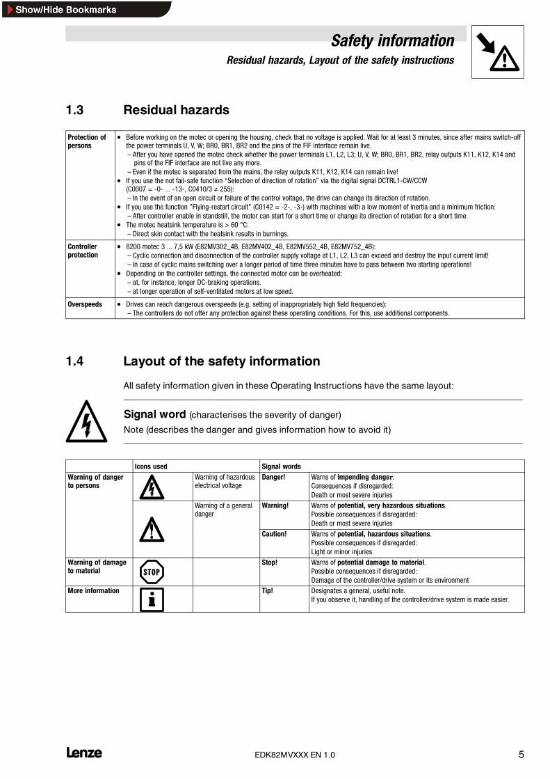
1.3 Residual hazards
Protection ofpersons
• Before working on the motec or opening the housing, check that no voltage is applied. Wait for at least 3 minutes, since after mains switch-offthe power terminals U, V, W; BR0, BR1, BR2 and the pins of the FIF interface remain live.– After you have opened the motec check whether the power terminals L1, L2, L3; U, V, W; BR0, BR1, BR2, relay outputs K11, K12, K14 andpins of the FIF interface are not live any more.
– Even if the motec is separated from the mains, the relay outputs K11, K12, K14 can remain live!• If you use the not fail-safe function “Selection of direction of rotation” via the digital signal DCTRL1-CW/CCW
(C0007 = -0- ... -13-, C0410/3 ≠ 255):– In the event of an open circuit or failure of the control voltage, the drive can change its direction of rotation.
• If you use the function ”Flying-restart circuit” (C0142 = -2-, -3-) with machines with a low moment of inertia and a minimum friction:– After controller enable in standstill, the motor can start for a short time or change its direction of rotation for a short time.
• The motec heatsink temperature is > 60 °C:– Direct skin contact with the heatsink results in burnings.
Controllerprotection
• 8200 motec 3 ... 7,5 kW (E82MV302_4B, E82MV402_4B, E82MV552_4B, E82MV752_4B):– Cyclic connection and disconnection of the controller supply voltage at L1, L2, L3 can exceed and destroy the input current limit!– In case of cyclic mains switching over a longer period of time three minutes have to pass between two starting operations!
• Depending on the controller settings, the connected motor can be overheated:– at, for instance, longer DC-braking operations.– at longer operation of self-ventilated motors at low speed.
Overspeeds • Drives can reach dangerous overspeeds (e.g. setting of inappropriately high field frequencies):– The controllers do not offer any protection against these operating conditions. For this, use additional components.
1.4 Layout of the safety information
All safety information given in these Operating Instructions have the same layout:
Signal word (characterises the severity of danger)
Note (describes the danger and gives information how to avoid it)
Icons used Signal wordsWarning of dangerto persons
Warning of hazardouselectrical voltage
Danger! Warns of impending danger.Consequences if disregarded:Death or most severe injuries
Warning of a generaldanger
Warning! Warns of potential, very hazardous situations.Possible consequences if disregarded:Death or most severe injuries
Caution! Warns of potential, hazardous situations.Possible consequences if disregarded:Light or minor injuries
Warning of damageto material
Stop! Warns of potential damage to material.Possible consequences if disregarded:Damage of the controller/drive system or its environment
More information Tip! Designates a general, useful note.If you observe it, handling of the controller/drive system is made easier.

Parameter settingParameter setting using the keypad
6 lEDK82MVXXX EN 1.0
2 Parameter setting
2.1 Parameter setting using the keypad
The keypad is available as accessory. A full description can be obtained from the informationincluded in the keypad delivery.
Function keys
Status display
Bargraph display
Function bar 1
Function bar 2
Parameter set
Code number Changes possible when Subcode number
Changes possible whenlamp is blinking
Parameter value with unit
2.1.1 Menu structure
All parameters for controller setting or monitoring are saved in codes under the menus User and all.The codes have numbers and are abbreviated in the text with a ”C” before the number. Somecodes store the parameters in numerical “subcodes” to ensure that parameter setting is clearlystructured (example: C0517 menu User).
• The menu User
– is active after every mains switching or keypad attachment during operation.– contains all codes for a standard application with linear V/f characteristic control (Lenze
setting).– can be modified as required under C0517.
• The menu all
– contains all codes.– shows a list of all codes in ascending order.
• The change between User and all and how to change parameters in the codes is describedon the following pages.

Parameter settingParameter setting using the keypad
7l EDK82MVXXX EN 1.0
2.1.2 The menu UUUUsssseeeerrrr - The 10 most important drive parameters
After mains switching or plugging in the keypad during operation, the 10 codes defined to be themost important in the user menu User (Code C0517) are available immediately.
In default setting the menu contains User all codes required for a standard application with linear V/fcharacteristic control.
Code Name Lenze settingC0050 Output frequency Display: Output frequency without slip compensationC0034 Setpoint selection range -0- Standard I/O X3/8: 0 ... 5 V / 0 ... 10 V / 0 ... 20 mAC0034 Setpoint selection range 0
Application I/OX3/1U: 0 ... 5 V / 0 ... 10 VX3/2U: 0 ... 5 V / 0 ... 10 V
C0007 Fixed configuration of digital inputs -0- E4 E3 E2 E1C0007 Fixed configuration of digital inputs 0CW/CCW DCB JOG2/3 JOG1/3
CW/CCW rotation DC-injection brake Selection of fixed setpointsC0010 Minimum output frequency 0.00 HzC0011 Maximum output frequency 50.00 HzC0012 Acceleration time main setpoint 5.00 secC0013 Deceleration time main setpoint 5.00 secC0015 V/f rated frequency 50.00 HzC0016 Umin boost depending on the inverter typeC0002 Parameter set transfer/reset see code table
Tip!Use C0002 ”Parameter set transfer” to easily transfer configurations from one controller to the otheror to reset the controller to Lenze settings.

Parameter settingParameter setting using the keypad
8 lEDK82MVXXX EN 1.0
2.1.3 Change between the menus UUUUSSSSEEEErrrr and AAAALLLLLLLL
000000
Hi Hz
Lo
1 PS
0002
000000
Hi Hz
Lo
1 PS
0002
000000
Hi Hz
Lo
1 PS
001 6
000000
Hi Hz
Lo
1 PS
001 5
000000
Hi Hz
Lo
1 PS
001 3
000000
Hi Hz
Lo
1 PS
001 2
000000
Hi Hz
Lo
1 PS
001 1
000000
Hi Hz
Lo
1 PS
001 0
000000
Hi Hz
Lo
1 PS
0007
000000
Hi Hz
Lo
1 PS
0034
000000
Hi Hz
Lo
1 PS
0050
~5 s
0000050000
1
PS
Hi Hz
Lo 5
USEr000
000
Hi Hz
Lo
1 PS
0988
000000
Hi Hz
Lo
1 PS
0001
000000
Hi Hz
Lo
1 PS
0007
ALL
000000
Hi Hz
Lo
1 PS
001 0
AL L000
Hi Hz
Lo
1 PS
0050
su er000
Hi Hz
Lo
1 PS
0050
8200vec075
2.1.4 Parameter change in menus
Step Keys Display Note Example1. Controller inhibit Only necessary if you want to change codes marked with “[ ]” in
the code table, e. g. [C0002].All other parameters can be changed during operation.
2. Set parameters Reduce C00123.
p
XXXX Select code 0012 (acceleration time)from 5 00 s to 1 00 s4.
001For codes without subcodes: Jump to (and then 6.) from 5.00 s to 1.00 s
5. XXX Select subcode6. 5.00 s7. XXXXX Set parameters 1.00 s8. STOre Acknowledge entry if blinking
Acknowledge entry if is not blinking; is not active9. Restart the ”loop” at 2. to set other parameters.

Troubleshooting and fault eliminationMaloperation of the drive
9l EDK82MVXXX EN 1.0
3 Troubleshooting and fault elimination
3.1 Maloperation of the drive
Fault Cause RemedyMotor does notrotate
DC-bus voltage too low(Red LED is blinking every 0.4 s;keypad display LU)
Check mains voltage
Controller inhibited(Green LED is blinking, keypad display: )
Remove the controller inhibit, controller inhibit can be setthrough several sources
Automatic start inhibited (C0142 = 0 or 2) LOW-HIGH edge at X3/28If necessary, correct start condition (C0142)
DC injection brake active (DCB) Deactivate DC-injection brakeMechanical motor brake is not released Manual or electrical release of mechanical motor brakeQuick stop (QSP) active (keypad display: ) Remove quick stopSetpoint = 0 Setpoint selectionJOG setpoint activated and JOG frequency = 0 JOG setpoint selection (C0037 ... C0039)Active fault Eliminate faultWrong parameter set active Change to correct parameter set via terminalControl mode C0014 = -4-, -5-, but no motor parameter identification Motor parameter identification (C0148)Under C0410 several functions, which exclude each other, are assigned to thesame signal source.
Correct configuration in C0410
Use internal voltage source X3/20 for function modules Standard-I/O, INTERBUS,PROFIBUS-DP or LECOM-B (RS485):Bridge between X3/7 and X3/39 is missing
Jumper terminals
Motor does not Defective motor cable Check motor cableMotor does notrotate smoothly Maximum current too low (C0022, C0023) Adaptation to applicationrotate smoothly
Motor underexcited or overexcited Check parameter setting (C0015, C0016, C0014)C0084, C0087, C0088, C0089, C0090, C0091 and/or C0092 are not adapted tothe motor data
Manual adaptation or identification of motor parameters(C0148)
Current Setting of C0016 too high Correct settingCurrentconsumption of Setting of C0015 too low Correct settingconsumption ofmotor too high C0084, C0087, C0088, C0089, C0090, C0091 and/or C0092 are not adapted to
the motor dataManual adaptation or identification of motor parameters(C0148)
Motor rotates,setpoints are“0”
With the function of the keypad a setpoint has been selected. Set the setpoint to ”0” by C0140 = 0
Motorparameteridentification
Motor too small compared with rated power
identificationstops with errorLP1
DC brake active via terminal
Unacceptabledrive responsewith vectorcontrol
various Vector control optimisation

Troubleshooting and fault eliminationError messages
10 lEDK82MVXXX EN 1.0
3.2 LEDs at the controller (operating status display)
LED Operating statusgreen redon off Controller enabledon on Mains switched on and automatic start inhibitedblinking off Controller inhibitedoff blinking every second Fault active, check under C0161off blinking every 0.4 seconds Undervoltage switch-offfast blinking off Motor parameter identification
3.3 Fault messages at the keypad or in the parameter settingprogram Global Drive Control
Display Fault Cause Remedy
Keypad PC 1)
noer 0 No fault - -
ccr 71 System fault Strong interferences on control cables Shield control cablesccr
y
Ground or earth loops in the wiring
ce0
61 Communication error to AIF Transmission of control commands via AIF isinterfered
Plug the communication module firmly into the handterminal
ce1
62 Communciation error atCAN-IN1 with sync control
CAN-IN1 object receives faulty data orcommunication interrupted
• Plug-in connection for bus module Check FIF• Check transmitter• Increase monitoring time under C0357/1 if necessary
ce2
63 Communication error toCAN-IN2
CAN-IN2 object receives faulty data orcommunication is interrupted
• Plug-in connection for bus module Check FIF• Check transmitter• Increase monitoring time under C0357/2 if necessary
ce3
64 Communication error toCAN-IN1 with event or timecontrol
CAN-IN1 object receives faulty data orcommunication interrupted
• Plug-in connection for bus module Check FIF• Check transmitter• Increase monitoring time under C0357/3 if necessary
ce4
65 BUS-OFF(many communication errorsoccurred)
Controller has received too many faulty telegramsvia system bus and has been disconnected from thebus
• Check whether the bus terminator is available• Check screen contact of the cables• Check PE connection• Check the bus load, if necessary, reduce the baud rate
ce5
66 CAN Time-Out With remote parameter setting via system bus(C0370):Slave does not respond. Communication monitoringtime exceeded
• Check wiring of the system bus• Check system bus configuration
Operation with module on FIF:Internal error
Contact Lenze
ce6
67 Function module system bus(CAN) is set to ”Warning” or”BUS-OFF”(only generated if C0128 = 1)
CAN controller sends ”Warning” or ”BUS-OFF” • Check whether the bus is terminated• Check screen contact of the cables• Check PE connection• Check the bus load, if necessary, reduce the baud rate
EEr
91 External error (TRIP-SET) A digital signal used for the function TRIP set hasbeen activated.
Check external encoder
H05
105 Internal fault Contact Lenze
id1
140 Faulty parameter identification Motor not connected Connect motor
LP1
32 Error in motor phase(only generated if C0597 = 1)
• Failure of one/several motor phase(s)• Motor current too low
• Check motor cables• Vmin boost
C t t ith di d tLP1 182 Error in motor phase(only generated if C0597 = 2)
min• Connect motor with corresponding power or adapt
motor under C0599
LU 1030 DC-bus undervoltage Mains voltage too low Check mains voltageLU
g
DC-bus voltage too low Check supply module
400 V controller connected to 240 V mains Connect the controller to the appropriate mains voltage
Troubleshooting and fault eliminationError messages
11l EDK82MVXXX EN 1.0
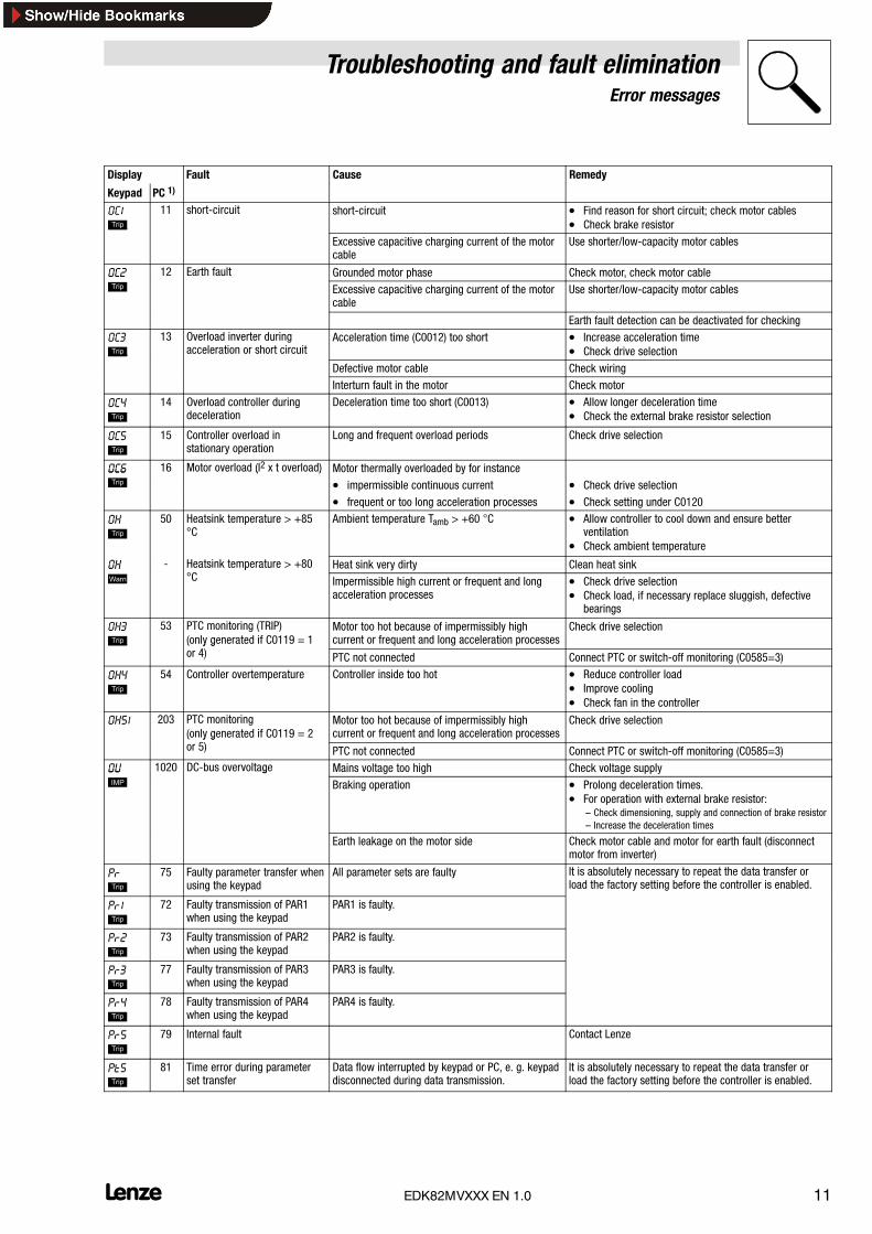
Display RemedyCauseFault
Keypad PC 1)
OC1
11 short-circuit short-circuit • Find reason for short circuit; check motor cables• Check brake resistor
Excessive capacitive charging current of the motorcable
Use shorter/low-capacity motor cables
OC2 12 Earth fault Grounded motor phase Check motor, check motor cableOC2 Excessive capacitive charging current of the motor
cableUse shorter/low-capacity motor cables
Earth fault detection can be deactivated for checking
OC3
13 Overload inverter duringacceleration or short circuit
Acceleration time (C0012) too short • Increase acceleration time• Check drive selection
Defective motor cable Check wiring
Interturn fault in the motor Check motor
OC4
14 Overload controller duringdeceleration
Deceleration time too short (C0013) • Allow longer deceleration time• Check the external brake resistor selection
OC5
15 Controller overload instationary operation
Long and frequent overload periods Check drive selection
OC6 16 Motor overload (I2 x t overload) Motor thermally overloaded by for instanceOC6
( )
• impermissible continuous current • Check drive selection
• frequent or too long acceleration processes • Check setting under C0120
OH
50 Heatsink temperature > +85°C
Ambient temperature Tamb > +60 C • Allow controller to cool down and ensure betterventilation
• Check ambient temperature
OH - Heatsink temperature > +80°C
Heat sink very dirty Clean heat sinkOH
p°C Impermissible high current or frequent and long
acceleration processes• Check drive selection• Check load, if necessary replace sluggish, defective
bearings
OH3
53 PTC monitoring (TRIP)(only generated if C0119 = 1
4)
Motor too hot because of impermissibly highcurrent or frequent and long acceleration processes
Check drive selection ( y g
or 4) PTC not connected Connect PTC or switch-off monitoring (C0585=3)
OH4
54 Controller overtemperature Controller inside too hot • Reduce controller load• Improve cooling• Check fan in the controller
OH51 203 PTC monitoring(only generated if C0119 = 2
)
Motor too hot because of impermissibly highcurrent or frequent and long acceleration processes
Check drive selection( y gor 5) PTC not connected Connect PTC or switch-off monitoring (C0585=3)
OU 1020 DC-bus overvoltage Mains voltage too high Check voltage supplyOU
g
Braking operation • Prolong deceleration times.• For operation with external brake resistor:
– Check dimensioning, supply and connection of brake resistor– Increase the deceleration times
Earth leakage on the motor side Check motor cable and motor for earth fault (disconnectmotor from inverter)
Pr
75 Faulty parameter transfer whenusing the keypad
All parameter sets are faulty It is absolutely necessary to repeat the data transfer orload the factory setting before the controller is enabled.
Pr1
72 Faulty transmission of PAR1when using the keypad
PAR1 is faulty.
Pr2
73 Faulty transmission of PAR2when using the keypad
PAR2 is faulty.
Pr3
77 Faulty transmission of PAR3when using the keypad
PAR3 is faulty.
Pr4
78 Faulty transmission of PAR4when using the keypad
PAR4 is faulty.
Pr5
79 Internal fault Contact Lenze
Pt5
81 Time error during parameterset transfer
Data flow interrupted by keypad or PC, e. g. keypaddisconnected during data transmission.
It is absolutely necessary to repeat the data transfer orload the factory setting before the controller is enabled.

Troubleshooting and fault eliminationError messages
12 lEDK82MVXXX EN 1.0
Display RemedyCauseFault
Keypad PC 1)
rSt
76 Faulty auto-TRIP reset More than 8 fault messages in 10 minutes Depends on the fault message
sd5
85 Open wire at analog input(setpoint range 4 ... 20 mA)
Current at analog input < 4 mA Close circuit at analog input
1) LECOM error number


Lenze Drives GmbH, Postfach 10 13 52, D-31763 Hameln Standort: Hans-Lenze-Straße 1, D-31855 Aerzen, Telefon +49 (0) 51 54 / 82-0, Telefax +49 (0) 51 54 / 82-21 11 Telefax Service +49 (0) 51 54 / 82-11 12 E-Mail: [email protected] · Internet: http://www.Lenze.com
Printed in Germany 04/10