Embed Size (px)
Citation preview

Rev. G 12/1/17
Econami Digital Sound Decoder
Steam User’s Guide Software Release 1.6
Previous software versions included
Notice The information in this document is subject to change without notice. SoundTraxx (Throttle Up! Corp.) shall not be liable for technical or editorial errors or omissions contained herein, nor for incidental or consequential damage resulting from the furnishing, performance or use of this material. This document contains information protected by copyright. No part of this document may be photocopied or reproduced in any form without the prior written consent of Throttle Up! Corp. Product names mentioned herein may be trademarks and/or registered trademarks of their respective companies. SoundTraxx, Econami, Tsunami, Tsunami2, SoundTraxx DCC, Dynamic Digital Exhaust, Auto-Exhaust, Hyperlight, Hyperdrive2, SoundCar, CurrentKeeper, and Intelligent Consisting are trademarks of Throttle Up! Corp.

Contents
All Aboard! ..................................................................................................................... 4
Overview ................................................................................................................................ 4
Using Econami for Steam ....................................................................................................... 5
CV Programming Tutorial ....................................................................................................... 9
Introduction to Programming .................................................................................................11
Basic Programming .................................................................................................... 15
Configuring the Address ........................................................................................................15
Configuring the Decoder ........................................................................................................16
Configuring Throttle and Braking ...........................................................................................18
Configuring Lighting Outputs .................................................................................................23
Configuring Sound Effects .....................................................................................................29
Configuring Automatic Sound ................................................................................................34
Advanced Programming ............................................................................................. 37
Configuring the Equalizer ......................................................................................................37
Configuring Dynamic Digital Exhaust .....................................................................................39
Configuring Function Mapping ...............................................................................................41
Configuring Hyperdrive2 ........................................................................................................47
Configuring for Advanced Consist Operation .........................................................................51
Miscellaneous Features .............................................................................................. 55
Configuring Analog Mode Operation ......................................................................................55
Operating With a CurrentKeeper™ ........................................................................................58
Troubleshooting .......................................................................................................... 59
Sorting Out Decoder Difficulties .............................................................................................59
Appendix A: Decimal-Hex-Binary Conversions ........................................................ 62
Appendix B: Steam Econami CV Reference ............................................................. 63
Appendix C: License Agreement ............................................................................... 64
Appendix D: Service and Warranty Policy ................................................................ 65
Appendix E: Declaration of Conformity .................................................................... 66

All Aboard!
Econami Steam User’s Guide 4
All Aboard!
Overview Congratulations on purchasing your SoundTraxx Econami Digital Sound Decoder (DSD) for steam locomotives! This user’s guide shows you how to operate Econami and customize each decoder setting to fit your preferences, while providing some helpful troubleshooting tips along the way.
We suggest referring to the user documents listed below as you read this user’s guide.
Econami Installation Guide
Provides instructions and strategies for successful sound installations. Econami Steam Technical Reference
Offers a list of all included CVs and details making adjustments to settings.
Econami Sound Selection References
Lists each included sound effect for configuring a prototypical operating experience. Decoder Selector
Assists in selecting the correct decoder and speaker for many models in all scales.
Videos Page
Provides instructional videos and product demonstrations.
Steam Sound Samples
Offers sound file previews of exhaust chuffs and steam whistle selections. Reference Documents
Includes helpful information such a glossary terms and specific installation information. Technical Notes
Provides notes about wiring practices and DCC compliance tests.
CurrentKeeper Reference
Includes supplemental information about operating and programming with this device.
Factory Installed Decoders
Visit this page for specific CV values and feature information for factory installed models.
These resources can be viewed and downloaded from our website at www.soundtraxx.com.

All Aboard!
Econami Steam User’s Guide 5
Using Econami for Steam The Econami Digital Sound Decoder (DSD) for steam is designed to enhance your model railroading experience, offering you sound just as realistic as your models – at an affordable cost. Discussed within this user’s guide, Econami provides an abundance of features, such as 28-function support, 20 Hyperlight lighting effects, Flex-Map function mapping technology, and back-EMF Hyperdrive2 advanced motor control, and drifting mode with Dynamic Digital Exhaust. Econami also provides selectable whistles, bells, exhaust chuffs, airpumps, and couplers to allow more versatility in creating your ideal model railroading experience. You can start using Econami right out of the package without making any adjustments. However, you may adjust settings at any time by making changes to Configuration Variables (CVs). Most DCC decoder and command station manuals call this “programming”, though this is misleading and sounds scarier than it is. At no point are you required to learn programming! This user’s guide will walk you through operating and programming Econami to its full capacity.
Default Function Assignments The first time you operate your Econami decoder, you will be able to activate features and sound effects by simply pressing the appropriate key on your cab or command station console. These are “default” function assignments. The effects listed in Table A are assigned to function keys F0-F28 by default. This section describes how to activate each effect with function keys. Note: You can assign any effect to function keys labeled as “Not Assigned” in Table A with Flex-Map function mapping CVs. Refer to “Configuring Function Mapping” for more information about customizing function assignments. Note: Pressing function keys F0-F28 will toggle functions “on” and “off” and activate effects.
Turn On the Lights Ensure your locomotive is in the forward direction, then turn on F0 to illuminate the headlight and spool up the dynamo. Reverse the locomotive direction to turn off the headlight and turn on the backup light. Pressing F0 a second time will turn off the dynamo, headlight, and backup light.
Note: On Econami UK Steam decoders the dynamo sound effect is not mapped to
F0. The dynamo is disabled from the factory but can be mapped to any function key using the Flex-Map function mapping feature.
Not included in software releases prior to version 1.3
Table A. Default Functions
Function Key Effect
F0(f) Headlight, Dynamo
F0(r) Backup Light, Dynamo
F1 Bell
F2 Whistle
F3 Short Whistle
F4 Cylinder Cocks
F5 Drifting Mode Enable
F6 Drifting Mode Disable
F7 Dimmer
F8 Mute
F9 Grade-Crossing Signal
F10 Blowdown
F11 Brake Squeal/Release
F12 Not Assigned
F13 Coupler, Coupler Release
F14 Switching Mode
F15 Not Assigned
F16 Water Stop
F17 Not Assigned
F18 Not Assigned
F19 Not Assigned
F20 Not Assigned
F21 Not Assigned
F22 Not Assigned
F23 “All Aboard!”/Coach Doors
F24 FX3 Function Output
F25 FX4 Function Output
F26 FX5 Function Output**
F27 FX6 Function Output**
F28 Not Assigned
**Available on select formats

All Aboard!
Econami Steam User’s Guide 6
Turn on F7 to dim the headlight or backup light before passing oncoming trains, or while waiting on a siding. Press F7 again to return the headlight and backup light outputs to full brightness.
Ring the Bell Turn on F1 to ring the bell. Press F1 again to stop ringing the bell. The bell is generally rung before moving the locomotive, when approaching crossings, to alert people or equipment near the track, and as a warning signal when necessary.
Note: On Econami UK Steam Decoders, the F1 key is defaulted to the Shunt Whistle effect, not the bell. The bell is disabled from the factory but can be mapped to any
function key using the Flex Map function mapping feature.
Blow the Whistle Signaling can make your operating sessions more fun! Engineers signal to notify passengers, crew, and other trains of common locomotive movements, such as stopping, moving forward, backing up, and approaching grade crossings. Econami provides three functions for signaling. Use F2, F3, and F9 to signal prototypically while you operate, as described below. Press and release F2 to blow the “long” whistle. Contrary to most function keys, the duration of the whistle blast is determined by how long you press F2. In other words, the whistle blast will start when you press F2, and stop when you release F2. Press F3 to issue the single “toot” of the “short” whistle. The short whistle will be the same length every time you press F3, unlike the playable whistle function (F2). Note: Function key F2 on the NCE Power Cab command station is on/off or “latching”, i.e., pressing F2 to turn on the function will start the whistle blast, and pressing F2 again to turn off the function will stop the whistle blast. To issue momentary whistle blasts with the NCE Power Cab, press and release the “Horn/Whistle” button instead of using F2. To issue the long-long-short-long grade-crossing signal automatically, turn on F9 as your locomotive approaches a grade crossing. Refer to Table B to view some more common signals.
Table B. Whistle Signals Long = –
Short = ●
Signal Description
– – ● – Approaching a grade crossing: hold final blast until crossing is occupied
● Applying brakes
– – Releasing brakes, proceeding forward
● ● ● When moving, stop; when stopped, back up
● ● ● ● Request signal from trainman
– ● ● ● Signal flagman to protect rear
– ● Warning signal: use when approaching areas with obstructed views and when approaching/passing passenger/freight trains
– Approaching stations, junctions, and railroad crossings at grades
Note: On Econami UK Steam Decoders, the Shunt Whistle effect is mapped to the F1 key and the Main Whistle effect is mapped to the F2 key. The F3 Short Whistle effect
will play a short blast of which ever whistle (Shunt or Main) blown last. The grade-crossing signal mapped to F9 is replaced with a “two-shorts” signal.

All Aboard!
Econami Steam User’s Guide 7
Activate Cylinder Cocks As you begin to accelerate from a stop, turn on F4 to purge the condensed water from the cylinder. The sound of the condensed water in the cylinder being expelled outwards with the steam, can be heard (“swish-swoosh”) as the engine moves.
Drifting Mode When your locomotive crests a grade and begins moving downhill, turn on F5 to simulate drifting. The locomotive will coast downhill and the decoder will mute the exhaust chuff and amplify the side rod clank. Drifting mode starts when the Johnson bar is set forward and the throttle is shut off. Turning off F6 will return all sound effects to their prior settings.
Mute Sound Effects Turn on F8 to mute all sound effects when you need to silence your train. The mute function allows a quick way to turn off sound effects for a phone call, for instance. Press F8 again to return all sound effect volume levels to their prior settings.
Blow Down the Boiler There’s sure to be particle buildup in the boiler of your engine. To clean the boiler’s mud ring, turn on F10 to open the blowdown valve and blow out the sediment. Turn off F10 to close the valve.
Apply and Release Brakes The brakes typically squeal just before the wheels stop turning. Turn on F11 before you decelerate to a stop. Before departing, turn off F11 to release the brakes.
Couple and Uncouple Turn on F13 to engage the coupler as you add cars to your train. When you uncouple, press F13 a second time to open the knuckle and separate the glad hands.
Use Switching Mode To improve throttle control for switching operations, turn on F14 to override all momentum CVs and reduce the current throttle setting by 50%. Press F14 again to reset locomotive speed to the prior speed step and reactivate all momentum CV settings. For more information about momentum CVs, refer to “Configuring Throttle and Braking.”
Activate Water Stop When your locomotive is stopped, turn on F16 to open the water hatch and fill the tender. Turn off F16 to stop filling the tender and close the hatch before departure.
Announce “All Aboard!” Turn on F23 before leaving the station to issue the conductor’s “all aboard!” announcement. After the coach doors slam shut, increase the throttle and depart the station.
Note: On Econami UK Steam Decoders, turning on F23 before leaving the station will issue a Guard whistle effect, not an “all aboard” announcement. After the coach doors
slam closed, increase the throttle and depart the station.
Turn On FX3-FX6 Lighting If you have additional lights wired to the FX3-FX6 function outputs, use function keys F24-F27 to activate them. Depending on board format, Econami offers up to six lighting outputs to support Hyperlight effects. To select Hyperlight effects for lighting outputs, refer to “Configuring Lighting Outputs.”

All Aboard!
Econami Steam User’s Guide 8
Make an Emergency Stop Press the emergency stop button to issue the emergency brake application and bring your train to an immediate stop.
Automatic Sound Effects Econami plays a variety sound effects automatically. Automatic sound effects respond prototypically to aspects of operation such as certain functions and speed settings.
Auto-Exhaust 2-cylinder exhaust for a light steam locomotive is Econami’s default setting, and the chuff rate is automatically regulated by the back-EMF sensor in response to motor load. For example, the chuff cadence will respond to changes in grade; the chuff becomes more rapid when the motor is spinning faster, and less rapid when the motor is impeded. To adjust the Auto-Exhaust chuff rate, refer to “Configuring Sound Effects.” When acceleration and deceleration rates have been set to non-zero values, the Dynamic Digital Exhaust (DDE) processor will automatically adjust the exhaust and side rod clank volume to simulate the engine building speed and coasting to a stop. You can also use F5 and F6 to simulate drifting manually if desired. Refer to “Configuring Throttle and Braking” to set acceleration and deceleration rates, and refer to “Configuring Dynamic Digital Exhaust” to adjust a given parameter of DDE throttle sensing. Furthermore, you can select 3-cylinder* or articulated type exhaust in place of 2-cylinder exhaust, and select from light, medium, heavy, and geared exhaust chuff types. Refer to “Configuring Sound Effects” for details regarding Econami’s exhaust selections.
Johnson Bar Changing the direction of the locomotive will automatically play the sound of the Johnson bar being moved forward or backward.
Side Rod Clank The “clanks” and “clunks” of the side rod occur with the exhaust chuff. You can use drifting mode to mute the exhaust chuff and elevate the volume of the side rod clank if desired.
Airpumps The airpump sound effect simulates air pressure being maintained in the reservoir during operation. The pump cadence will revert to its most rapid setting every time you engage the coupler and every third time you apply the brake function.
Note: On Econami UK Steam Decoders, the vacuum pump is the default.
Blower The blower simulates draft being maintained near the exhaust nozzle in the smokebox during operation.
* Not included in software releases prior to version 1.3

All Aboard!
Econami Steam User’s Guide 9
CV Programming Tutorial What is a CV? Configuration Variable (CV) is the industry-adopted term for a decoder’s user-adjustable memory locations. CVs allow you to adjust various decoder properties and customize your operating experience. The address, audio settings, motor control, lighting effects, and function assignments are just some of the properties you can adjust with CVs. You can modify CVs at any time and the decoder will save your settings even when the power is turned off. If reading about CV programming already has your head spinning, this tutorial will help you understand how CVs work. At first glance, you may feel overwhelmed by the large number of CVs offered by Econami. Don’t worry! You don’t need an engineering degree to customize your decoder’s settings. As you have already seen, the decoder has been shipped with all CVs pre-programmed so you can begin using your locomotive immediately without having to worry about what adjustments to make. Making adjustments is easy, and you can customize settings one CV at a time. As you become comfortable with its operation, move onto a new section and begin exploring the options and capabilities found there. Detailed information on any CV can be found in the Tsunami2 Steam Technical Reference. When in doubt, you can always reset the decoder to factory defaults. Refer to “Resetting CVs (Starting Over)” for more information.
Bits and Bytes All the bits, bytes, and other symbols used in decoder manuals as well as differences between command stations can make CV programming difficult to understand. The problem is compounded further by differences in each command station manufacturer’s user interface. Put simply, each CV contains a value that can be changed, and changing the value of a CV will modify a specific decoder setting. Each CV is made up of one byte (i.e., eight bits). However, knowing a little more about how CV values are represented will help you make the right adjustments. CV values are commonly represented in the two numeric formats listed below.
Binary Like computers, binary is the numbering system used in all DCC decoders. Binary units are called “bits” and can be represented as either 0 or 1.
Decimal Decimal representation is the format you will probably use most often. Each CV contains a decimal value from 0 to 255. We have tried to use the decimal number system in this manual when describing the proper values to program into a given CV; however, you will occasionally find values listed in the Technical Reference in both binary and decimal forms. For those more familiar with the binary method of programming, we have provided a handy-dandy conversion table in Appendix A that allows one to quickly convert between decimal, binary and hex (for some older command stations).
Programming by the Bits Most CVs contain a single piece of data which can be represented in decimal or binary. For example, CV 128 (Master Volume) can be loaded with any value from 0 to 255 and it will always and only affect one thing – the overall volume of the decoder.
All Aboard!
Econami Steam User’s Guide 10
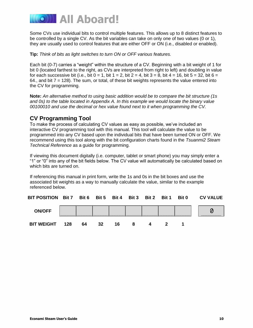
Some CVs use individual bits to control multiple features. This allows up to 8 distinct features to be controlled by a single CV. As the bit variables can take on only one of two values (0 or 1), they are usually used to control features that are either OFF or ON (i.e., disabled or enabled). Tip: Think of bits as light switches to turn ON or OFF various features. Each bit (0-7) carries a “weight” within the structure of a CV. Beginning with a bit weight of 1 for bit 0 (located farthest to the right, as CVs are interpreted from right to left) and doubling in value for each successive bit (i.e., bit 0 = 1, bit 1 = 2, bit 2 = 4, bit 3 = 8, bit 4 = 16, bit 5 = 32, bit 6 = 64., and bit 7 = 128). The sum, or total, of these bit weights represents the value entered into the CV for programming. Note: An alternative method to using basic addition would be to compare the bit structure (1s and 0s) to the table located in Appendix A. In this example we would locate the binary value 00100010 and use the decimal or hex value found next to it when programming the CV.
CV Programming Tool To make the process of calculating CV values as easy as possible, we’ve included an interactive CV programming tool with this manual. This tool will calculate the value to be programmed into any CV based upon the individual bits that have been turned ON or OFF. We recommend using this tool along with the bit configuration charts found in the Tsuanmi2 Steam Technical Reference as a guide for programming. If viewing this document digitally (i.e. computer, tablet or smart phone) you may simply enter a “1” or “0” into any of the bit fields below. The CV value will automatically be calculated based on which bits are turned on. If referencing this manual in print form, write the 1s and 0s in the bit boxes and use the associated bit weights as a way to manually calculate the value, similar to the example referenced below.
BIT POSITION Bit 7 Bit 6 Bit 5 Bit 4 Bit 3 Bit 2 Bit 1 Bit 0 CV VALUE
ON/OFF ______ ______ ______ ______ ______ ______ ______ ______
________
BIT WEIGHT 128 64 32 16 8 4 2 1

All Aboard!
Econami Steam User’s Guide 11
Introduction to Programming This section details CV programming modes, reading CVs, accessing indexed CVs, resetting CVs to factory defaults, and locking and unlocking CVs. Due to the varying CV programming methods used by DCC systems, we cannot provide comprehensive instructions that address every command station and must assume you understand the capabilities of your system on some level. Consult your DCC system manual or contact the manufacturer if you need more detailed programming instructions.
Programming Modes Econami supports Operations Mode and Service Mode programming.
Operations Mode Referred to as “Ops Mode” or “programming on the main,” Operations Mode allows you to program CVs during operation even when other locomotives and rolling stock are present. Being able to program during operation simplifies re-creating prototypical scenarios. For example, you can increase the momentum of a locomotive after it couples to a train. However, because data cannot be read back from the decoder, programming on the main will not allow you to verify CV values.
Service Mode Service Mode programming usually requires connecting the model to a dedicated programmer or placing it on a separate programming track. Econami supports four types of Service Mode instructions:
Address Mode: CV 1 may be modified Register Mode: CVs 1, 2, 3, 4, 7, 8, and 29 may be modified Paged Mode: A page register is used to modify any CV indirectly Direct Mode: All CVs may be directly modified
Reading CVs Some command stations permit you to read the value of a CV and verify its setting in Service Mode programming. If you have trouble reading or verifying CVs, there may be a problem within the command station’s design rather than with the decoder. Try another programming mode if you experience difficulties programming or reading CVs. Many of the newer DCC systems automatically select the appropriate programming mode and only require you to enter the CV number and desired value. However, some DCC systems may restrict the number of available CVs. If you’re having difficulty determining the programming modes supported by your DCC system, refer to the manual or contact the manufacturer. Note: Econami does not require a programming track booster, such as the PTB-100.
Configuration Variable Control CVs
CV 8: Manufacturer ID CV 15: CV Unlock Code CV 16: CV Lock ID CV 30: Error Information CV 31: CV Index 1 CV 32: CV Index 2 CVs 1.257-1.512: Indexed CV Page 1 CVs 2.257-2.512: Indexed CV Page 2
All Aboard!
Econami Steam User’s Guide 12
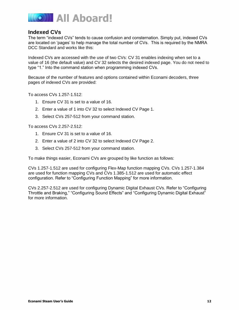
Indexed CVs The term “indexed CVs” tends to cause confusion and consternation. Simply put, indexed CVs are located on ‘pages’ to help manage the total number of CVs. This is required by the NMRA DCC Standard and works like this: Indexed CVs are accessed with the use of two CVs: CV 31 enables indexing when set to a value of 16 (the default value) and CV 32 selects the desired indexed page. You do not need to type “1.” Into the command station when programming indexed CVs. Because of the number of features and options contained within Econami decoders, three pages of indexed CVs are provided:
To access CVs 1.257-1.512:
1. Ensure CV 31 is set to a value of 16.
2. Enter a value of 1 into CV 32 to select Indexed CV Page 1.
3. Select CVs 257-512 from your command station. To access CVs 2.257-2.512:
1. Ensure CV 31 is set to a value of 16.
2. Enter a value of 2 into CV 32 to select Indexed CV Page 2.
3. Select CVs 257-512 from your command station. To make things easier, Econami CVs are grouped by like function as follows: CVs 1.257-1.512 are used for configuring Flex-Map function mapping CVs. CVs 1.257-1.384 are used for function mapping CVs and CVs 1.385-1.512 are used for automatic effect configuration. Refer to “Configuring Function Mapping” for more information. CVs 2.257-2.512 are used for configuring Dynamic Digital Exhaust CVs. Refer to “Configuring Throttle and Braking,” “Configuring Sound Effects” and “Configuring Dynamic Digital Exhaust” for more information.

All Aboard!
Econami Steam User’s Guide 13
Resetting CVs (Starting Over) Occasionally, a programming error ay occur and the decoder might not respond as you would’ve expected. Usually, this is caused by one or more CVs inadvertently being programmed to the wrong value. The CVs can be quickly reset to their factory default values. Follow the steps below to perform either a full or partial CV reset:
1. Turn on track power to the decoder. If you have a SoundTraxx CurrentKeeper™ or another device that maintains power, allow at least two minutes for charging before programming.
2. Enter one of the following values into CV 8 (Manufacturer ID) to perform a full or partial CV reset:
CV 8: Manufacturer ID
8 = Reset All CVs 9 = Reset CVs 1-128
10 = Reset CVs 129-256 11 = Reset CVs 1.257-1.512 12 = Reset CVs 2.257-2.512 13 = Reset CVs 3.257-3.512
3. Turn off track power to the decoder. Wait 5 seconds then return power to the decoder. If you have installed a SoundTraxx CurrentKeeper or another device that maintains track power, ensure that the device is fully discharged (usually about 3-4 minutes) before returning power.
4. Wait about 10 seconds after returning power to the decoder. All lights (headlight, backup light or effect lights), as well as the decoder’s error light, will flash 16 times to indicate CVs have been successfully reset. Econami will respond to primary address 3 after all CVs, or CVs 1-128 have been reset.
Note: Continue cycling power to the decoder if the CV reset is unsuccessful. If you are unable to reset CV values, continue to “Locking and Unlocking CVs” to verify the decoder is not locked.
Locking and Unlocking CVs The CV lock/unlock feature is designed to secure the decoder and prevent the inadvertent programming of CVs. For example, if you have installed a function decoder in addition to the sound decoder, you may wish to lock the CVs in one decoder while programming the other. To use the CV lock feature implemented in CVs 15 and 16, bit 0 of CV 30 must first be set to 1 (the default value is 0). This is to avoid accidently locking the decoder when the CV lock feature is not needed. CV 15 is the unlock code and may be programmed to any value from 0 to 255 regardless of whether the decoder is locked or unlocked. CV 16 is the lock code and may be set to any value from 0 to 7. CV 16 can only be programmed when the decoder is unlocked. Attempts to program CV 16 with a value greater than 7 will be ignored. The decoder is unlocked when the value in CV 15 matches the value in CV 16. Otherwise the decoder is locked and cannot be programmed in either Operations Mode or Service Mode. Further, a locked decoder cannot be reset to its factory defaults until it is unlocked. Econami decoders are shipped from the factory with all CVs unlocked, that is, CV 15 and 16 are both set to 0.
Locking and Unlocking CVs
CV 15: CV Unlock Code
CV 16: CV Lock ID
CV 30: Error Information

All Aboard!
Econami Steam User’s Guide 14
If the decoder is unlocked, changing the value in CV 16 will instantly lock the decoder. You must then set CV 15 to the same value as was just programmed into CV 16 to unlock the decoder again. If you use the CV locking feature for a multi-decoder installation in one model, each decoder must first have its lock code set prior to the installation of any other decoders. First install one decoder and program its lock code. Then install the next decoder and program its lock code. Since the first decoder is now locked, it will be unaffected by the programming of the second decoder. If you accidentally set the lock code of the two decoders to the same value you will need to disconnect one decoder and start over. Continue in this manner until all decoders have been installed and their lock codes have been set. Follow the steps below to lock and unlock CVs:
1. Enter a value of 1 into CV 30 (Error Information) to enable the CV lock/unlock feature.
2. Enter a value from 0 to 7 into CV 16 to set the lock code.
3. To unlock CVs, set CV 15 to the same value as CV 16.
4. To lock CVs, set CV 15 to a different value than CV 16 to unlock CVs. It is a good idea to set up a standardized system so you don’t forget the lock code settings. You might, for example, set all motor decoders to a CV lock code of 1, sound decoders to a lock code of 2, and function decoders to a lock code of 3. Keeping CV 15 set to 0 will guarantee the decoder stays locked until you are ready to begin programming.
If You Forget the Lock Code As there are only eight possible combinations, you can easily determine a forgotten lock code using trial and error with the following procedure:
1. Place the model on the programming track and enter a value of 0 into CV 15.
2. Try reading the value of CV 16. If the value is not read back, CVs are locked.
3. Enter a value of 1 into CV 15 and try reading the value of CV 16 again.
4. If the value is not read back, enter a value of 2 into CV 15 and try again.
5. Enter values 3-7 into CV 15 until the value of CV 16 is read back and CVs are unlocked. If you still can’t identify the lock code, there may be a problem with the installation, programming track, or decoder. Contact SoundTraxx Customer Support if this occurs. If you do not have access to a programming track with read-back capabilities (or are uncertain as to whether it is working properly), you can also use Operations Mode to discover the lock code by alternately programming CV 15 and setting another CV to a value where there is a known response. For example, changing CV 128 (Master Volume Control) will provide auditory feedback as to whether the decoder is unlocked by virtue of a change in sound level. Thus, you would begin by setting CV 15 to 0 and then setting CV 128 to 0. If the volume does not reduce to 0, the decoder is locked. Then set CV 15 to 1 and try programming CV 128 again. Repeat this process until you find a value for CV 15 that results in a change in sound volume as you change CV 128. Troubleshooting Tip: Even if you are not planning to use the CV Lock feature, it can still be accidentally activated by inadvertently programming CV 15 or 16 with a non-default value. If you have a decoder that is otherwise working properly (i.e., making sound and responding to throttle commands) but has suddenly stopped accepting CV changes, then first run through the procedure under “If You Forget The Lock Code” to determine if the decoder has been locked.
Basic Programming
Econami Steam User’s Guide 15
Basic Programming
Configuring the Address Like all DCC decoders, Econami responds to primary address 3 right out of the package. Address control CVs allow you to set primary and extended addresses or your choice, which can be useful when matching the decoder’s address with the number on the locomotive, for instance. Since most command stations will guide you through the process simply follow their instructions for programming your decoder address. We’ve included information about the CVs used to configure your decoder’s address for those who have older command stations or models that does not provide prompts for this process.
Setting Addresses Econami recognizes either the primary address (also known as the short address) in CV 1 or the extended (long) address in CVs 17-18. Whether you use the primary or extended address will first depend on whether or not your DCC system uses extended addressing (not all of them do, so if in doubt, see your command station owner’s manual.) Second, it will depend on your preferences and the numbering scheme you use for setting your decoder addresses. The extended address has the advantage that you can use all four digits of a locomotive’s road number for the decoder address making it easy to remember. Be aware that some DCC systems do not support the full range of available addresses. Programming Notes: You can set the primary and extended addresses in Service Mode (on the programming track) at any time. Some DCC systems also allow you to set the address in Operations Mode according to the following restrictions:
If the decoder’s primary address is enabled (bit 5 of CV 29 set to 0), only the extended address can be changed in Operations Mode.
If the decoder’s extended address is enabled (bit 5 of CV 29 set to 1), only the primary address can be changed in Operations Mode.
Primary Address The Primary address is commonly referred to as the “short” or “2-digit” address. Enter a value from 1 to 127 into CV 1 to set the primary address. All SoundTraxx decoders are set to primary address 3 by default. When selecting the locomotive with your DCC throttle, only enter “3” into the method used to select locomotives. Entering “03” or “0003” can inadvertently choose the extended address, which is not configured as the decoder’s default address type.
Extended Address Often referred to as the “long” or “4-digit” address, the extended address is actually made up of two CVs, 17 and 18. Unless you are an experienced user, you should not try to program these CVs individually as a specific protocol is required in order for the decoder to accept the new data (see the Econami Steam Technical Reference for details). After setting the extended address, set bit 5 of CV 29 (Configuration Data 1) to 1 to enable its usage. If bit 5 of CV 29 is set to 0, the decoder will continue to respond to the primary address. Continue to “Configuring the Decoder” for more information about CV 29.
Address Control CVs
CV 1: Primary Address
CVs 17-18: Extended Address

Basic Programming
Econami Steam User’s Guide 16
Configuring the Decoder CV 29 controls a variety of important settings. It determines locomotive direction, speed-step mode, alternate power source, speed tables, and the decoder address.
Configuring CV 29 This is the first CV that you’ll encounter which will need to be programmed by the bits. Refer to the “CV Programming Tutorial” for an interactive guide to programming multiple features in a single CV.
DIR: Locomotive Direction Bit 0 (DIR) is used to determine locomotive direction. Setting bit 0 to 1 will invert direction commands, and the decoder will interpret forward as reverse, and reverse as forward. This operating mode is most useful for setting up diesel engines that ran with the long hood section forward. However, it is also useful for electronically correcting installations where the motor wires were accidentally reversed and avoids dismantling the locomotive a second time.
F0: F0 Location (Speed-Step Mode Select) Bit 1 (F0) is used to determine the number of speed steps within the throttle range. 14, 28, and 128 speed-step modes are available, and 28/128 speed-step mode has been enabled by default. Select the highest number of speed steps supported by your command station for the most refined throttle operation.
APS: Alternate Power Source (Analog Mode) Setting bit 2 (APS) to 1 will allow the decoder to use an analog power source when a DCC signal is not present. Entering a value of 1 into CV 12 (Alternate Power Source) will enable analog mode (disabled by default). Refer to “Configuring for Analog Mode Operation” for more information.
STE: Speed Table Enable Setting bit 4 (STE) to 1 will select a linear or 28-point custom speed table in place of the 3-point speed table. Refer to “Configuring Throttle and Braking” for more information.
EAM: Primary or Extended Address Bit 5 (EAM) is used for selecting the active address. Setting bit 5 to 0 will enable the primary address. Set the primary address with CV 1 (Primary Address). CVs 17 and 18 (Extended Address) are used to set the extended address. Set bit 5 of CV 29 to 1 to enable the extended address. Refer to the previous section, “Configuring the Address,” for more information about setting the extended address.
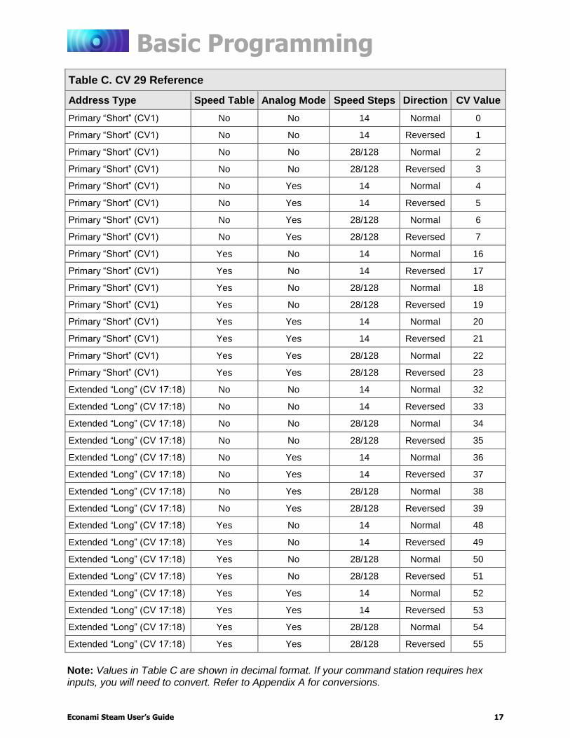
Refer to Table C on the following page to view decimal values for CV 29.
Decoder Configuration CVs
CV 29: Configuration Data 1
Bit 7 Bit 6 Bit 5 Bit 4 Bit 3 Bit 2 Bit 1 Bit 0
0 0 EAM STE 0 APS F0 DIR
Basic Programming
Econami Steam User’s Guide 17
Table C. CV 29 Reference
Address Type Speed Table Analog Mode Speed Steps Direction CV Value
Primary “Short” (CV1) No No 14 Normal 0
Primary “Short” (CV1) No No 14 Reversed 1
Primary “Short” (CV1) No No 28/128 Normal 2
Primary “Short” (CV1) No No 28/128 Reversed 3
Primary “Short” (CV1) No Yes 14 Normal 4
Primary “Short” (CV1) No Yes 14 Reversed 5
Primary “Short” (CV1) No Yes 28/128 Normal 6
Primary “Short” (CV1) No Yes 28/128 Reversed 7
Primary “Short” (CV1) Yes No 14 Normal 16
Primary “Short” (CV1) Yes No 14 Reversed 17
Primary “Short” (CV1) Yes No 28/128 Normal 18
Primary “Short” (CV1) Yes No 28/128 Reversed 19
Primary “Short” (CV1) Yes Yes 14 Normal 20
Primary “Short” (CV1) Yes Yes 14 Reversed 21
Primary “Short” (CV1) Yes Yes 28/128 Normal 22
Primary “Short” (CV1) Yes Yes 28/128 Reversed 23
Extended “Long” (CV 17:18) No No 14 Normal 32
Extended “Long” (CV 17:18) No No 14 Reversed 33
Extended “Long” (CV 17:18) No No 28/128 Normal 34
Extended “Long” (CV 17:18) No No 28/128 Reversed 35
Extended “Long” (CV 17:18) No Yes 14 Normal 36
Extended “Long” (CV 17:18) No Yes 14 Reversed 37
Extended “Long” (CV 17:18) No Yes 28/128 Normal 38
Extended “Long” (CV 17:18) No Yes 28/128 Reversed 39
Extended “Long” (CV 17:18) Yes No 14 Normal 48
Extended “Long” (CV 17:18) Yes No 14 Reversed 49
Extended “Long” (CV 17:18) Yes No 28/128 Normal 50
Extended “Long” (CV 17:18) Yes No 28/128 Reversed 51
Extended “Long” (CV 17:18) Yes Yes 14 Normal 52
Extended “Long” (CV 17:18) Yes Yes 14 Reversed 53
Extended “Long” (CV 17:18) Yes Yes 28/128 Normal 54
Extended “Long” (CV 17:18) Yes Yes 28/128 Reversed 55
Note: Values in Table C are shown in decimal format. If your command station requires hex inputs, you will need to convert. Refer to Appendix A for conversions.

Basic Programming
Econami Steam User’s Guide 18
Configuring Throttle and Braking You can use throttle and braking control CVs to customize the decoder’s throttle and braking settings to your operating preferences. This section details setting acceleration and deceleration rates, setting braking rates for the F11 Brake function, adjusting speed table settings, and enabling motor trim scaling factors. If this is overwhelming at first glance, don’t worry! It’s not necessary to change all of them if you don’t want to. We’ve already talked about speed step selection in CV 29.
Setting the Start Voltage Econami provides CV 2, Vstart, to set the starting voltage that is applied to the motor at Speed Step 1, and is used to compensate for inefficiencies in the locomotive’s motor and driveline. CV 2 may be programmed with any value between 0 and 255 with each step in value being about 0.5% of the maximum available motor voltage. To calculate the value of CV 2, you can use the formula:
Desired Starting Voltage
CV 2 = 255 x ——————————————
Maximum Motor Voltage
If your DCC system supports Operations Mode Programming, an alternative method for setting Vstart is to turn your throttle to the first speed step and then use the operations mode programming feature to increase the value in CV 2 until the locomotive just begins to move.
Setting Momentum Rates Econami provides two CVs to simulate the momentum due to train weight. CV 3 (Baseline Acceleration Rate) controls how fast the locomotive responds to increases in throttle settings. CV 4 (Baseline Deceleration Rate) controls how fast the locomotive will respond to decreases in the throttle setting. Both CVs can be programmed with any value from 0 to 255, with 255 corresponding to the slowest acceleration or deceleration rate. Lower settings yield a more responsive locomotive, which is useful for switching. When both CVs are set to 0, the locomotive will respond nearly instantly to any throttle changes. A setting of 255, on the other hand, will require several minutes for a locomotive to reach full speed from a standing stop. Setting acceleration and deceleration rates can allow the speed of the locomotive to match the sound effects regulated by Dynamic Digital Exhaust. When using 14 or 28 speed-step mode, configuring acceleration and deceleration rates will improve the decoder’s throttle response. This allows the locomotive to speed up and slow down without lurching from one speed step to the next.
Configure the F11 Brake The F11 brake function is not only used to activate the brake squeal sound effect, but can also be configured to simulate the brakes being applied. CV 117 (F11 Brake Rate) is used to set the deceleration rate that will occur when F11 brake function is turned on.
Throttle Control CVs
CV 2: Vstart CV 3: Baseline Acceleration Rate CV 4: Baseline Deceleration Rate CV 5: Vhigh CV 6: Vmid CV 25: Speed Table Enable CV 29: Configuration Data 1 CV 66: Forward Motor Trim CVs 67-94: Custom Speed Table CV 95: Reverse Motor Trim CV 117: F11 Brake Rate
Basic Programming
Econami Steam User’s Guide 19
Values from 0 to 255 may be programmed into CV 117. However, these values are interpreted by the decoder as a range from -127 to +127. Furthermore, values from 0 to 127 are interpreted as 0 to +127, whereas values from 128 to 255 are interpreted as 0 to -127. The value (-127 to +127) is added to the value of CV 4 (Baseline Deceleration Rate) and sets the braking rate. Higher values indicate longer braking rates. We recommend setting CV 3 (Baseline Acceleration Rate) to a minimum value of 20 before setting CV 117 so that the acceleration rate is comparable to the deceleration rate. If the combined value of CVs 4 and 117 is less than 0, or if CV 117 is set to 0 or 128, the F11 brake function will have no effect on the motor. Note: When consisting with active momentum and braking rates, ensure the values of CVs 3, 4, & 117 are the same for all units.

Basic Programming
Econami Steam User’s Guide 20
Setting the 3-Point Speed Curve By default, track voltage is distributed to the decoder with no variation in a straight line and the decoder responds instantly to the throttle setting. You can designate the amount of voltage applied at the first, middle, and last speed step with CV 2 (Vstart), CV 5 (Vhigh), and CV 6 (Vmid) to compensate for track power or throttle control inefficiencies. First, set bit 4 (STE) of CV 29 to 0. Then enter values from 1 to 255 into CVs 2, 5, and 6 to set the 3-point speed curve. Each value is equivalent to roughly 0.5% of the total supply voltage. Use the calculations below to determine starting, mid-point, and maximum voltage settings:
Vstart, Vmid, Vhigh = Supply Voltage × CV Value ÷ 255 Note: Use CV 218 (Analog Mode Motor Start Voltage) to set the starting voltage level for analog mode operation. Refer to “Configuring for Analog Mode Operation” for more information. If your system supports Operations Mode, refer to the steps below for an alternative method of setting the 3-point speed curve:
1. Place the unit on the mainline and set the throttle to speed-step 1, and then increase the value of CV 2 until the model responds to your preferred starting voltage.
2. Set the throttle to a medium speed step, and then increase the value of CV 6 until the model responds to your preferred mid-speed voltage.
3. Set the throttle to the maximum speed step, and then increase the value of CV 5 until the model responds according to your preferred high-speed voltage level.
Use the 3-Point Speed Curve The figure shown below gives an example of how CVs 2, 5, and 6 can be used to change voltage levels during operation.
Basic Programming
Econami Steam User’s Guide 21
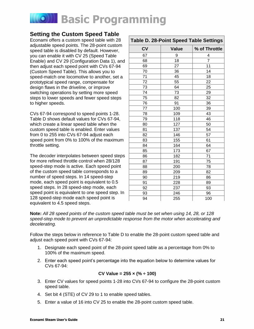
Setting the Custom Speed Table Econami offers a custom speed table with 28 adjustable speed points. The 28-point custom speed table is disabled by default. However, you can enable it with CV 25 (Speed Table Enable) and CV 29 (Configuration Data 1), and then adjust each speed point with CVs 67-94 (Custom Speed Table). This allows you to speed-match one locomotive to another, set a prototypical speed range, compensate for design flaws in the driveline, or improve switching operations by setting more speed steps to lower speeds and fewer speed steps to higher speeds. CVs 67-94 correspond to speed points 1-28. Table D shows default values for CVs 67-94, which create a linear speed table when the custom speed table is enabled. Enter values from 0 to 255 into CVs 67-94 adjust each speed point from 0% to 100% of the maximum throttle setting. The decoder interpolates between speed steps for more refined throttle control when 28/128 speed-step mode is active. Each speed point of the custom speed table corresponds to a number of speed steps. In 14 speed-step mode, each speed point is equivalent to 0.5 speed steps. In 28 speed-step mode, each speed point is equivalent to one speed step. In 128 speed-step mode each speed point is equivalent to 4.5 speed steps. Note: All 28 speed points of the custom speed table must be set when using 14, 28, or 128 speed-step mode to prevent an unpredictable response from the motor when accelerating and decelerating. Follow the steps below in reference to Table D to enable the 28-point custom speed table and adjust each speed point with CVs 67-94:
1. Designate each speed point of the 28-point speed table as a percentage from 0% to 100% of the maximum speed.
2. Enter each speed point’s percentage into the equation below to determine values for CVs 67-94:
CV Value = 255 × (% ÷ 100)
3. Enter CV values for speed points 1-28 into CVs 67-94 to configure the 28-point custom speed table.
4. Set bit 4 (STE) of CV 29 to 1 to enable speed tables.
5. Enter a value of 16 into CV 25 to enable the 28-point custom speed table.
Table D. 28-Point Speed Table Settings
CV Value % of Throttle
67 9 4
68 18 7
69 27 11
70 36 14
71 45 18
72 55 22
73 64 25
74 73 29
75 82 32
76 91 36
77 100 39
78 109 43
79 118 46
80 127 50
81 137 54
82 146 57
83 155 61
84 164 64
85 173 67
86 182 71
87 191 75
88 200 78
89 209 82
90 219 86
91 228 89
92 237 93
93 246 96
94 255 100

Basic Programming
Econami Steam User’s Guide 22
Setting Motor Trim CV 66 (Forward Motor Trim) and CV 95 (Reverse Motor Trim) are used to “trim” the forward and reverse drive voltages when the 28-point custom speed table is enabled. Setting motor trim can help compensate for speed differences between forward and reverse directions. For instance, if the throttle setting is the same in both directions and the locomotive appears to be moving faster in reverse, you can use CVs 66 and 95 to correct the speed difference. Entering values from 0 to 255 into CVs 66 and 95 will multiply the forward and reverse drive voltages by a scaling factor. Enter values from 1 to 127 to decrease speed. Enter values from 129 to 255 to increase speed. Entering a value of 0 or 128 into CVs 66 and 95 will set the scaling factor to 1 and will not modify the decoder’s drive voltage. Note: Bit 4 (STE) of CV 29 (Configuration Data 1) must be set to 1 for the motor trim scaling factors in CVs 66 and 95 to modify forward and reverse drive voltages.
Motor Trim CV Values
0 = Disabled
1 = Voltage × 0.008
↓ 127 = Voltage × 0.99
128 = Disabled
129 = Voltage × 1.008
↓ 255 = Voltage × 1.99
Basic Programming
Econami Steam User’s Guide 23
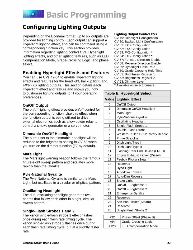
Configuring Lighting Outputs Depending on the Econami format, up to six outputs are provided for lighting control. Each output can support a Hyperlight lighting effect, and can be controlled using a corresponding function key. This section provides information regarding lighting control CVs, Hyperlight lighting effects, and other lighting features, such as LED Compensation Mode, Grade-Crossing Logic, and phase select.
Enabling Hyperlight Effects and Features You can use CVs 49-54 to enable Hyperlight lighting effects and features for the headlight, backup light, and FX3-FX6 lighting outputs. This section details each Hyperlight effect and feature and shows you how to customize lighting outputs to fit your operating preferences.
On/Off Output The on/off lighting effect provides on/off control for the corresponding function. Use this effect when the function output is being utilized to drive external electronics such as a low power relay to control a smoke generator or a servo motor.
Dimmable On/Off Headlight The output set to the dimmable headlight will be reduced to the brightness setting in CV 63 when you turn on the dimmer function (F7 by default).
Mars Light The Mars light warning beacon follows the famous figure-eight sweep pattern and oscillates more rapidly than the Gyralite.
Pyle-National Gyralite The Pyle-National Gyralite is similar to the Mars Light, but oscillates in a circular or elliptical pattern.
Oscillating Headlight The dual-oscillating headlight generates two beams that follow each other in a tight, circular sweep pattern.
Single-Flash Strobes 1 and 2 The xenon single-flash strobe 1 effect flashes once during each flash rate timing cycle. The xenon single-flash strobe 2 flashes once during each flash rate timing cycle, but at a slightly faster rate.
Lighting Output Control CVs
CV 49: Headlight Configuration CV 50: Backup Light Configuration CV 51: FX3 Configuration CV 52: FX4 Configuration CV 53: FX5 Configuration * CV 54: FX6 Configuration * CV 57: Forward Direction Enable CV 58: Reverse Direction Enable CV 59: Hyperlight Flash Rate CV 60: Grade-Crossing Hold Time CV 61: Brightness Register 1 CV 62: Brightness Register 2 CV 63: Dimmer Level
* Available on select formats
Table E. Hyperlight Select
Value Lighting Effect
0 On/Off Output
1 Dimmable On/Off Headlight
2 Mars Light
3 Pyle-National Gyralite
4 Oscillating Headlight
5 Single-Flash Strobe 1
6 Double-Flash Strobe
7 Western-Cullen D312 Rotary Beacon
8 Prime Stratolite
9 Ditch Light Type I
10 Ditch Light Type II
11 Flashing Rear End Device (FRED)
12 Engine Exhaust Flicker (Diesel)
13 Firebox Flicker (Steam)
14 Reserved
15 Dyno-Light
16 Auto-Dim Forward
17 Auto-Dim Reverse
18 Brake Light
19 On/Off – Brightness 1
20 On/Off – Brightness 2
21 Emergency Gyralite
22 Reserved
23 Ash Pan Flicker (Steam)
24 Reserved
25 Single-Flash Strobe 2
+32 Phase Offset (Phase B)
+64 Grade-Crossing Logic
+128 LED Compensation Mode

Basic Programming
Econami Steam User’s Guide 24
Double-Flash Strobe The xenon double-flash strobe effect emits two rapid flashes of light during each flash rate timing cycle. CV 59 is used to modify the flash rate timing cycle.
Western-Cullen D312 Rotary Beacon The Western-Cullen D312 Rotary Beacon effect follows a revolving reflector and bulb assembly flash-pattern.
Prime Stratolite The Stratolite is made up of four individual lamps arranged in a circular pattern. The Stratolite flashes in a clockwise direction in a mechanical “stepped” fashion, unlike the smooth motion of the rotary beacon.
Ditch Lights Type I and II Ditch lights type I and II flash together by default. When Grade-Crossing Logic is enabled, ditch light I assumes a steady “on” state before and after the crossing hold timer countdown. Conversely, ditch light II will remain off before and after the crossing hold timer countdown. To configure alternating ditch lights, set one lighting output to ditch light I or II and enable Grade-Crossing Logic, and then set a second lighting output to the same ditch light and enable Grade-Crossing Logic and phase offset.
FRED (Flashing Rear End Device) The FRED effect is a flashing red taillight that indicates the rear of the train.
Exhaust Flicker This effect produces a random flicker whose intensity increases with locomotive speed. This effect is best used by placing a red/orange LED in the exhaust stack. As the locomotive increases speed, it will glow brighter, imitating an increase in sparks and exhaust gases.
Firebox Flicker This effect produces a random flicker whose intensity resembles a burning fire and can be used with a lamp placed in the firebox area. The effect is improved when two lights are used, one yellow and one red or orange and each connected to a separate function output.
Dyno-Light The Dyno-light effect synchronizes the lamp brightness with the output of the dynamo to simulate the spool-up and shut off of the dynamo, and the heating and cooling of the bulb filament. The brightness increases as the dynamo heats up and decreases as it cools down.
Auto-Dim Forward and Reverse The auto-dim forward effect will automatically dim lighting outputs to the dimmer level in CV 63 when in the forward direction, and the auto-dim reverse effect will automatically dim lighting outputs to the dimmer level in CV 63 when in the reverse direction.
Brake Light The brake light effect is dimmed to the brightness setting in CV 63 when active. The brake light brightness level will be automatically set to 100% when you turn on the independent or train brake function (F11 by default).
Basic Programming
Econami Steam User’s Guide 25
On/Off Brightness 1 and 2 On/Off Brightness effects 1 and 2 allow you to independently adjust the level of up to 2 lighting outputs. You can accurately recreate low brilliance lighting effects on your model such as class lights, lit number boards or marker lamps. The on/off brightness 1 and 2 effects will set lighting outputs to the brightness levels of CVs 61 and 62, respectively.
Emergency Gyralite The emergency Gyralite follows the same oscillating sweep pattern as the Gyralite, and will automatically disable all active lighting effects.
Ash Pan Flicker The ash pan flicker effect slowly flickers from 25% to 100% brightness to simulate the glowing embers that filter into the ash pan from the firebox.
Phase Offset Add a value of 32 to the value of flashing Hyperlight effects to set the corresponding lighting output to Phase B from Phase A. Flashing effects set to Phase B will flash opposite of flashing effects set to Phase A, i.e., Phase A turns off when Phase B turns on, and Phase A turns on when Phase B turns off.
Grade-Crossing Logic Grade-Crossing Logic allows you to set up lighting functions, the bell, and whistle to automatically simulate encountering grade crossings. Add a value of 64 to enable Grade-Crossing Logic. Turning on the whistle function (F2 by default) or the grade-crossing signal function (F9 by default) will start the crossing hold timer countdown and allow lighting effects to assume a flashing state. Shown in Table F, flashing Hyperlight effects will return to an on or off state after the countdown ends. Practice activating Grade-Crossing Logic as your locomotive approaches a grade crossing. You can adjust the crossing hold timer countdown from 0 to 15 seconds by entering a value from 0 to 15 into CV 60 (Grade-Crossing Hold Time). To allow the bell to ring during the crossing hold timer countdown, enable the grade-crossing bell feature in CV 122 (Bell Select). Refer to “Configuring Sound Effects” for more information about the grade-crossing bell.
Refer to Table F located on the next page for a list of Hyperlight effects commonly configured with Grade Crossing Logic (including alternating ditch lights) and corresponding CV values.

Basic Programming
Econami Steam User’s Guide 26
Table F. Commonly Configured Hyperlight Effects
Effect Type
CV Value Grade Crossing
Logic Effect State Crossing Logic Off Crossing Logic On
Phase A Phase B Phase A Phase B
Mars Light 2 34 66 98 On
Pyle-National Gyralite 3 35 67 99 On
Oscillating Headlight 3 36 68 100 On
Single-Flash Strobe 1 5 37 69 101 Off
Single-Flash Strobe 2 25 57 89 131 Off
Double-Flash Strobe 6 38 70 102 Off
D312 Rotary Beacon 7 39 71 103 Off
Prime Stratolite 8 40 72 104 Off
Ditch Light I 9 41 73 105 On
Ditch Light II 10 42 74 106 Off
FRED 11 43 75 107 Off
LED Compensation Mode The brightness of an incandescent bulb is determined by voltage, whereas an LED’s brightness is determined by current. LED Compensation Mode alters the method of sending current to the LED to balance the LED and incandescent brightness levels. Add a value of 128 to enable LED Compensation Mode for the corresponding lighting output. Note: Enabling LED Compensation Mode will not change the output voltage. Resistors may still be necessary depending on the board format and drive voltage of the LED.

Basic Programming
Econami Steam User’s Guide 27
Adjusting Lighting Output Settings After configuring Hyperlight effects and features with CVs 49-54, adjust CV 57 (Forward Direction Enable), CV 58 (Reverse Direction Enable), CV 59 (Hyperlight Flash Rate), CV 61 (Brightness Register 1), CV 62 (Brightness Register 2), CV 63 (Dimmer Level), and CV 64 (Master Brightness Register) to customize lighting output direction, the Hyperlight flash rate, and brightness levels.
Enable Lighting Output Direction CV 57 determines the lighting outputs active in the forward direction, and CV 58 determines lighting outputs active in the reverse direction. Table G shows values used to enable lighting outputs for the forward and reverse directions. To enable lighting outputs for the forward direction, add the values of your preferred lighting outputs and enter the sum into CV 57. To enable lighting outputs for the reverse direction, add the values of your preferred lighting outputs and enter the sum into CV 58. The headlight is disabled in the reverse direction and the backup light is disabled for the forward direction by default.
Set the Hyperlight Flash Rate Adjust the flash rate of flashing Hyperlight effects from the fastest setting to the slowest setting by entering a value from 0 to 15 into CV 59.
Adjust Brightness Registers 1 and 2 Adjust the brightness level of lighting outputs set to the on/off brightness 1 effect from 0% to 100% by entering a value from 0 to 255 into CV 61. Adjust the brightness level of lighting outputs set to the on/off brightness 2 effect from 0% to 100% by entering a value from 0 to 255 into CV 62.
Adjust the Dimmer Level Adjust the brightness level of the dimmer function (F7 by default) from 0% to 100% by entering a value from 0 to 255 into CV 63. The dimmer level is set to 60% brightness by default.
Table G. CVs 57-58 Values
Lighting Output CV Value
Headlight +1 to enable
Backup Light +2 to enable
FX3 Output +4 to enable
FX4 Output +8 to enable
FX5 Output +16 to enable
FX6 Output +32 to enable

Basic Programming
Econami Steam User’s Guide 28
Example: Gyralite with Grade Crossing Logic and Firebox Flicker This example details using CV 51 (FX3 Configuration) and CV 52 (FX4 Configuration) to enable a Gyralite effect with Grade-Crossing Logic and a Firebox Flicker effect. Follow the steps below to set the FX3 lighting output to an on/off output with a Gyralite effect in Grade-Crossing logic and the Firebox Flicker effect to FX4.
1. Add the CV values for Grade-Crossing Logic (64) and Gyralite effects (3):
64 + 3 = 67
2. Enter a value of 67 into CV 51 to set the FX3 lighting output to a Gyralite and enable the Grade-Crossing Logic. Add a value of 128 for LED Compensation Mode, if using LEDs.
3. Enter a value of 13 into CV 52 to set the FX4 lighting output to Firebox Flicker effect. Add a value of 128 for LED Compensation Mode, if using LEDs.
Now “light off” the fire in the firebox by turning on FX4 (F25 by default) and watch the intensity of the fire change as fuel is burned.
Next, turn on F24 (by default) to enable the FX3 output. It will remain in a steady “on” state until your locomotive approaches a grade crossing and the whistle function (F2 by default) is turned on to activate Grade-Crossing Logic. The FX3 output will then change from a constant “on” state to a Gyralite effect. The FX3 output will revert to a steady “on” state after the crossing hold timer countdown ends.
Example: Headlight and Backup Light Direction This example details using CVs 57 and 58 to configure the directionality of the headlight and backup light outputs. Follow the steps below to turn the headlight and the backup lights on regardless of direction:
1. Note the bit definitions and the decimal value of each bit for CVs 57 and 58 (See Table G.). Bits 0-5 correspond to lighting outputs.
2. Setting all bits (0-5) to 1 in CV 57 will enable all lights in the forward direction. To do this, simply add the decimal values of all the outputs:
1 + 2 + 4 + 8 + 16 + 32 = 63 3. Enter a value of 63 into CV 57 to enable all lights in the forward direction.
4. Setting all other bits (0-5) to 1 in CV 58 will enable all lights in the reverse direction. To do this, simply add the decimal values of all the outputs:
1 + 2 + 4 + 8 + 16 + 32 = 63 5. Enter a value of 63 into CV 58 to enable all lights in the reverse direction.
Basic Programming
Econami Steam User’s Guide 29
Configuring Sound Effects Sound control CVs allow you to fully customize the decoder’s sound effects to fit your preferences. All sound effects included in Econami are recordings from actual locomotives and simulate the reality of operating a steam locomotive.
This section shows you how to:
1. Select different exhaust chuffs, whistles, bells, dynamos, airpumps, and couplers in place of the default sound effects.
2. Customize engine exhaust control such as 2-cylinder, 3-cylinder and articulated exhaust chuff.
3. Adjust the chuff rate
4. Adjust the volume levels of primary sound effect mixer channels, and enable quiet mode.
Selecting Sound Effects You can select exhaust chuffs, whistles, alternate whistles, bells, airpumps, dynamos, and couplers with sound effect select CVs.
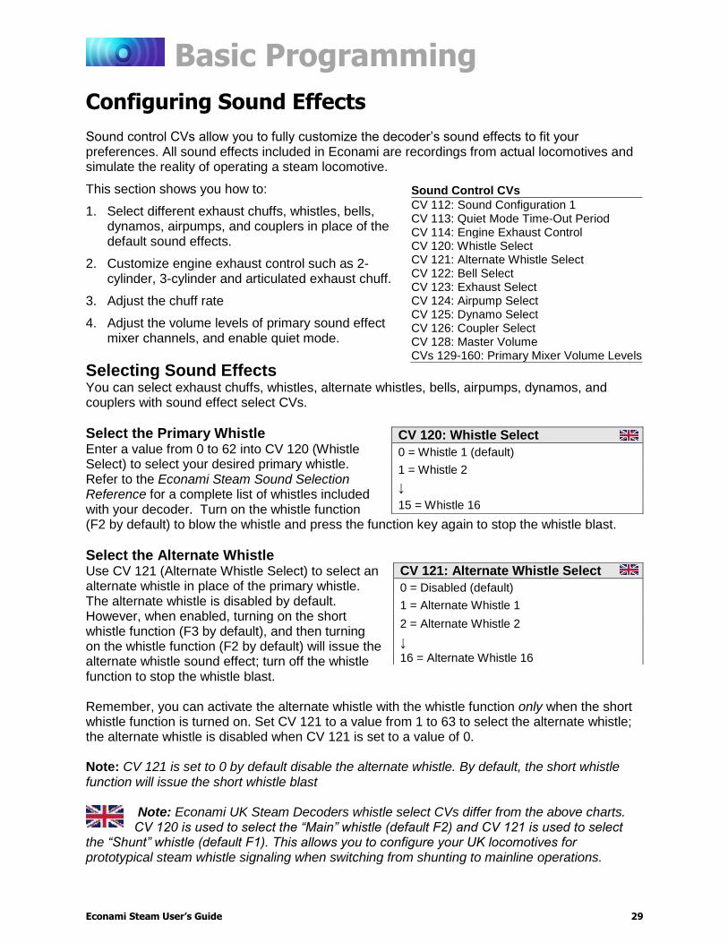
Select the Primary Whistle Enter a value from 0 to 62 into CV 120 (Whistle Select) to select your desired primary whistle. Refer to the Econami Steam Sound Selection Reference for a complete list of whistles included with your decoder. Turn on the whistle function (F2 by default) to blow the whistle and press the function key again to stop the whistle blast.
Select the Alternate Whistle Use CV 121 (Alternate Whistle Select) to select an alternate whistle in place of the primary whistle. The alternate whistle is disabled by default. However, when enabled, turning on the short whistle function (F3 by default), and then turning on the whistle function (F2 by default) will issue the alternate whistle sound effect; turn off the whistle function to stop the whistle blast. Remember, you can activate the alternate whistle with the whistle function only when the short whistle function is turned on. Set CV 121 to a value from 1 to 63 to select the alternate whistle; the alternate whistle is disabled when CV 121 is set to a value of 0. Note: CV 121 is set to 0 by default disable the alternate whistle. By default, the short whistle function will issue the short whistle blast
Note: Econami UK Steam Decoders whistle select CVs differ from the above charts. CV 120 is used to select the “Main” whistle (default F2) and CV 121 is used to select
the “Shunt” whistle (default F1). This allows you to configure your UK locomotives for prototypical steam whistle signaling when switching from shunting to mainline operations.
Sound Control CVs
CV 112: Sound Configuration 1 CV 113: Quiet Mode Time-Out Period CV 114: Engine Exhaust Control CV 120: Whistle Select CV 121: Alternate Whistle Select CV 122: Bell Select CV 123: Exhaust Select CV 124: Airpump Select CV 125: Dynamo Select CV 126: Coupler Select CV 128: Master Volume CVs 129-160: Primary Mixer Volume Levels
CV 120: Whistle Select
0 = Whistle 1 (default)
1 = Whistle 2
↓
15 = Whistle 16
CV 121: Alternate Whistle Select
0 = Disabled (default)
1 = Alternate Whistle 1
2 = Alternate Whistle 2
↓
16 = Alternate Whistle 16

Basic Programming
Econami Steam User’s Guide 30
Select the Bell Each decoder version has a selection of bells with pre-configured ring rates. Refer to the Econami Steam Sound Selection Reference to determine the range of values. For each bell, a range of up to 5 values is available. Within that range, higher values correspond to faster ring rates. Enter the desired value into CV 122 and turn on the bell function (F1 by default) to ring the bell. Press the function key again to stop the bell from ringing. Add a value of 128 to enable the grade-crossing bell. Enabling the grade-crossing bell in CV 122 allows the bell to ring during the crossing hold timer countdown after activating Grade-Crossing Logic with the whistle function (F2 by default). For more information about Grade-Crossing Logic, refer to “Configuring Lighting Outputs.”
Note: On Econami UK Steam Decoders, the F1 key is mapped to the shunt whistle function, not the bell. The bell is disabled from the factory but can be mapped to any
function key using the Flex Map function mapping feature.
Select the Exhaust Enter a value from 0 to 3 into CV 123 (Exhaust Select) to select your desired exhaust chuff. The exhaust chuff is automatically regulated by Dynamic Digital Exhaust and auto-exhaust. Refer to the Econami Steam Sound Selection Reference for a complete list of exhaust chuffs included with your decoder.
Note: Econami UK Steam Decoders exhaust chuff selections differ from the above chart.
Select the Airpump Setting CV 124 (Airpump Select) to a value from 0 to 4 will select one of five airpump sound effects. You can select a cross-compound airpump in place of single-phase, activate dual airpumps, or enable a vacuum pump.
Note: Econami UK Steam Decoders use option 4, the Vacuum Pump, as the default Airpump.
Select the Dynamo CV 125 (Dynamo Select) is used to select one of four dynamo sound effects. Set CV 125 to a value from 0 to 3 to select your preferred dynamo.
Note: Econami UK Steam Decoders have the dynamo volume (CV 133) muted. The
dynamo effect is also not mapped to the F0(f) F0(r) key.
CV 123: Exhaust Chuff Select
0 = Light (default) 1 = Medium 2 = Heavy 3 = Geared
CV 124: Airpump Select
0 = Single-phase (default) 1 = Cross-compound 2 = Dual single-phase 3 = Dual cross-compound 4 = Vacuum Pump
CV 125: Dynamo Select
0 = Dynamo 1 (default) 1 = Dynamo 2 2 = Dynamo 3 3 = Dynamo 4
Basic Programming
Econami Steam User’s Guide 31
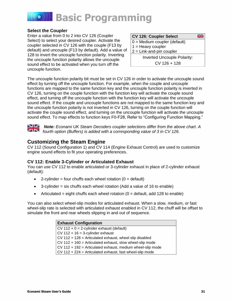
Select the Coupler Enter a value from 0 to 2 into CV 126 (Coupler Select) to select your desired coupler. Activate the coupler selected in CV 126 with the couple (F13 by default) and uncouple (F13 by default). Add a value of 128 to invert the uncouple function polarity. Inverting the uncouple function polarity allows the uncouple sound effect to be activated when you turn off the uncouple function. The uncouple function polarity bit must be set in CV 126 in order to activate the uncouple sound effect by turning off the uncouple function. For example, when the couple and uncouple functions are mapped to the same function key and the uncouple function polarity is inverted in CV 126, turning on the couple function with the function key will activate the couple sound effect, and turning off the uncouple function with the function key will activate the uncouple sound effect. If the couple and uncouple functions are not mapped to the same function key and the uncouple function polarity is not inverted in CV 126, turning on the couple function will activate the couple sound effect, and turning on the uncouple function will activate the uncouple sound effect. To map effects to function keys F0-F28, Refer to “Configuring Function Mapping.”
Note: Econami UK Steam Decoders coupler selections differ from the above chart. A fourth option (Buffers) is added with a corresponding value of 3 in CV 126.
Customizing the Steam Engine CV 112 (Sound Configuration 1) and CV 114 (Engine Exhaust Control) are used to customize engine sound effects to fit your operating preferences.
CV 112: Enable 3-Cylinder or Articulated Exhaust You can use CV 112 to enable articulated or 3-cylinder exhaust in place of 2-cylinder exhaust (default):
2-cylinder = four chuffs each wheel rotation (0 = default)
3-cylinder = six chuffs each wheel rotation (Add a value of 16 to enable)
Articulated = eight chuffs each wheel rotation (0 = default, add 128 to enable) You can also select wheel-slip modes for articulated exhaust. When a slow, medium, or fast wheel-slip rate is selected with articulated exhaust enabled in CV 112, the chuff will be offset to simulate the front and rear wheels slipping in and out of sequence.
Exhaust Configuration
CV 112 + 0 = 2-cylinder exhaust (default)
CV 112 + 16 = 3-cylinder exhaust
CV 112 + 128 = Articulated exhaust, wheel slip disabled
CV 112 + 160 = Articulated exhaust, slow wheel-slip mode
CV 112 + 192 = Articulated exhaust, medium wheel-slip mode
CV 112 + 224 = Articulated exhaust, fast wheel-slip mode
CV 126: Coupler Select
0 = Medium coupler (default) 1 = Heavy coupler 2 = Link-and-pin coupler
Inverted Uncouple Polarity:
CV 126 + 128

Basic Programming
Econami Steam User’s Guide 32
Adjust the Chuff Rate Adjust the cadence of the exhaust chuff to match your locomotive’s wheel rotations with CV 114. Entering values from 1 to 255 into CV 114 will determine the chuff rate. High values indicate more rapid chuffs, and low values indicate less rapid chuffs. CV 114 should merely be used to bring the chuff rate in line with wheel rotations. Setting CV 114 to a value of 0 will disable Auto-Exhaust. Place the locomotive on level track and increase the throttle from zero. If the chuff rate does not match the wheel rotations, enter higher or lower values into CV 114 until synchronized. The decoder will automatically adjust the cadence of the chuff to compensate for changes in motor load and speed.
Adjusting Volume Levels Volume control CVs allow you to set the master volume level for all sound effects, set the volume level of each sound effect, and enable quiet mode. Values from 0 to 255 may be programmed into any of the volume mixer CVs (Master Volume, Primary Mixer or Alternate Mixer) to set the volume level from 0% to 100%.
Adjust the Master Volume Level CV 128 (Master Volume) is used to adjust the volume level of all enabled sound effects, i.e., all mixer channels. Values from 0 to 255 may be programmed into CV 128 to set the volume level from 0% to 100%.
Adjust Primary Mixer Volume Levels CVs 129-160 (Primary Mixer Volume Levels) are used for setting the volume level of each sound effect, similar to a modern sound studio mixing board. Like CV 128 (Master Volume), values from 0 to 255 may be programmed into mixer channel CVs to adjust volume levels. For the best sound quality, optimize the volume levels by first determining the sound effect that should be the loudest. The whistle, for instance, usually creates the loudest sound. Then, adjust the volume levels of the remaining of the sound effects relative to the whistle. When you have all the sound effects to their respective volume levels, adjust the overall volume level with CV 128 as needed. Adjusting volume levels calls for a certain level of prudence to avoid “clipping” or “limiting,” which occurs when the sum of two or more signals exceeds the capacity of the output channel. Clipping is the clicking or popping sounds you may have heard through a pair of broken headphones or speakers. To avoid clipping, consider the sounds you play at the same time and make sure their volume levels aren’t set too high. For example, the whistle should be as loud as possible without causing clipping. If you start to hear some distortion, lower the volume level accordingly. Note: Be sure that your speaker is rated to match the audio amplifier of your decoder. Ratings for each format are available on the packaging and at www.soundtraxx.com. Failure to do so could cause severe damage to your speaker.
Refer to Table H on the next page to view default values for CVs 128-160.
CV 114: Exhaust Control
0 = Auto-Exhaust disabled
1 = Slowest chuff rate
↓
57 = Default
↓
255 = Fastest chuff rate
Basic Programming
Econami Steam User’s Guide 33
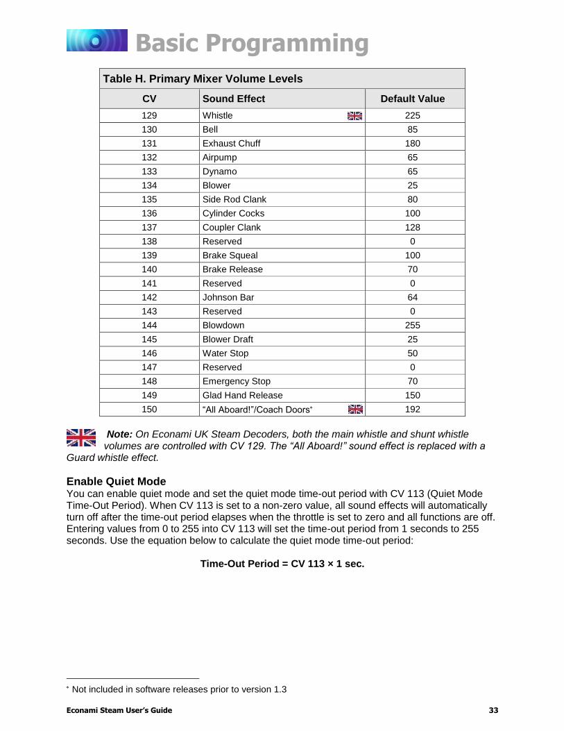
Table H. Primary Mixer Volume Levels
CV Sound Effect Default Value
129 Whistle 225
130 Bell 85
131 Exhaust Chuff 180
132 Airpump 65
133 Dynamo 65
134 Blower 25
135 Side Rod Clank 80
136 Cylinder Cocks 100
137 Coupler Clank 128
138 Reserved 0
139 Brake Squeal 100
140 Brake Release 70
141 Reserved 0
142 Johnson Bar 64
143 Reserved 0
144 Blowdown 255
145 Blower Draft 25
146 Water Stop 50
147 Reserved 0
148 Emergency Stop 70
149 Glad Hand Release 150
150 “All Aboard!”/Coach Doors 192
Note: On Econami UK Steam Decoders, both the main whistle and shunt whistle volumes are controlled with CV 129. The “All Aboard!” sound effect is replaced with a
Guard whistle effect.
Enable Quiet Mode You can enable quiet mode and set the quiet mode time-out period with CV 113 (Quiet Mode Time-Out Period). When CV 113 is set to a non-zero value, all sound effects will automatically turn off after the time-out period elapses when the throttle is set to zero and all functions are off. Entering values from 0 to 255 into CV 113 will set the time-out period from 1 seconds to 255 seconds. Use the equation below to calculate the quiet mode time-out period:
Time-Out Period = CV 113 × 1 sec.
Not included in software releases prior to version 1.3
Basic Programming
Econami Steam User’s Guide 34
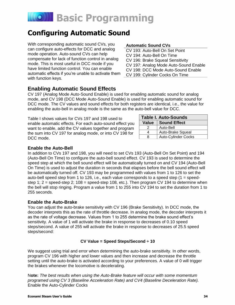
Configuring Automatic Sound With corresponding automatic sound CVs, you can configure auto-effects for DCC and analog mode operation. Auto-sound CVs can help compensate for lack of function control in analog mode. This is most useful in DCC mode if you have limited function control. You can enable automatic effects if you’re unable to activate them with function keys.
Enabling Automatic Sound Effects CV 197 (Analog Mode Auto-Sound Enable) is used for enabling automatic sound for analog mode, and CV 198 (DCC Mode Auto-Sound Enable) is used for enabling automatic sound for DCC mode. The CV values and sound effects for both registers are identical, i.e., the value for enabling the auto-bell in analog mode is the same as the auto-bell value for DCC. Table I shows values for CVs 197 and 198 used to enable automatic effects. For each auto-sound effect you want to enable, add the CV values together and program the sum into CV 197 for analog mode, or into CV 198 for DCC mode.
Enable the Auto-Bell In addition to CVs 197 and 198, you will need to set CVs 193 (Auto-Bell On Set Point) and 194 (Auto-Bell On Time) to configure the auto-bell sound effect. CV 193 is used to determine the speed step at which the bell sound effect will be automatically turned on and CV 194 (Auto-Bell On Time) is used to adjust the duration in seconds that elapses before the bell sound effect will be automatically turned off. CV 193 may be programmed with values from 1 to 126 to set the auto-bell speed step from 1 to 126, i.e., each value corresponds to a speed step (1 = speed-step 1; 2 = speed-step 2; 108 = speed-step 108, etc.). Then program CV 194 to determine when the bell will stop ringing. Program a value from 1 to 255 into CV 194 to set the duration from 1 to 255 seconds.
Enable the Auto-Brake You can adjust the auto-brake sensitivity with CV 196 (Brake Sensitivity). In DCC mode, the decoder interprets this as the rate of throttle decrease. In analog mode, the decoder interprets it as the rate of voltage decrease. Values from 1 to 255 determine the brake sound effect’s sensitivity. A value of 1 will activate the brake in response to decreases of 0.10 speed steps/second. A value of 255 will activate the brake in response to decreases of 25.5 speed steps/second:
CV Value = Speed Steps/Second ÷ 10 We suggest using trial and error when determining the auto-brake sensitivity. In other words, program CV 196 with higher and lower values and then increase and decrease the throttle setting until the auto-brake is activated according to your preferences. A value of 0 will trigger the brakes whenever the locomotive is decelerating. Note: The best results when using the Auto-Brake feature will occur with some momentum programed using CV 3 (Baseline Acceleration Rate) and CV4 (Baseline Deceleration Rate). Enable the Auto-Cylinder Cocks
Automatic Sound CVs
CV 193: Auto-Bell On Set Point CV 194: Auto-Bell On Time CV 196: Brake Squeal Sensitivity CV 197: Analog Mode Auto-Sound Enable CV 198: DCC Mode Auto-Sound Enable CV 199: Cylinder Cocks On Time
Table I. Auto-Sounds Value Sound Effect
2 Auto-Bell
4 Auto-Brake Squeal
8 Auto-Cylinder Cocks

Basic Programming
Econami Steam User’s Guide 35
Enable the Auto-Cylinder Cocks In addition to CVs 197 and 198, you will need to set CV 199 (Cylinder Cocks On Time) to configure the auto-cylinder cocks sound effect. CV 199 (Cylinder Cocks On Time) is used to adjust the duration the automatic cylinder cocks sound effect remains active after the engine is started. Entering values from 1 to 255 into CV 199 will adjust the duration from 1 to 255 seconds. The cylinder cocks sound effect will automatically turn off when the time period has elapsed. A value of 0 will disable automatic cylinder cocks.
Modifying Automatic Sound Effects Sound control CVs additionally allow you to modify automatic sound effects, such as the coach door slams that occur after the conductor’s “all aboard!” announcement.
Adjust the Coach Door Count Enter a value from 0 to 15 into CV 195 (Coach Door Count) to adjust the random number of coach door slams that occur with the all aboard/coach doors function. Turn on the all aboard/coach doors function while the locomotive is stopped to activate the conductor’s “all aboard!” announcement, followed by the random number of coach doors slams determined by the value of CV 195
Note: On UK Econami Steam Decoders, turning on F23 before leaving the station will issue a Guard whistle effect, not an “all aboard” announcement.
Example: Adjusting Sound Control CVs Using the information stated previously in this section, this example will guide you through configuring sound according to the following combination of adjustments:
CV 112: Select articulated exhaust with a fast wheel-slip rate
CV 113: Set the quiet mode time-out period to 30 seconds
CV 114: Synchronize the Auto-Exhaust chuff rate
CV 120: Select whistle 7
CV 121: Select alternate whistle 8
CV 122: Select bell 3 with a medium-fast ring rate and enable the grade-crossing bell
CV 123: Select the heavy exhaust chuff
CV 124: Enable dual cross-compound airpumps
CV 125: Select dynamo 4
CV 126: Select the heavy coupler with inverted uncouple function polarity
CV 195: Disable coach door slams
CV 199: Set the cylinder cocks on time to 15 seconds
1. Set CV 120 (Whistle Select) to a value of 6 to select whistle 7 as the primary whistle.
2. Set CV 121 (Alternate Whistle Select) to a value of 8 to select whistle 8 as the alternate whistle.
Not included in software releases prior to version 1.3
CV 195: Coach Door Count
0 = 0 door slams
1 = 1 door slam
↓
5 = 5 door slams (default)
↓
15 = 15 door slams
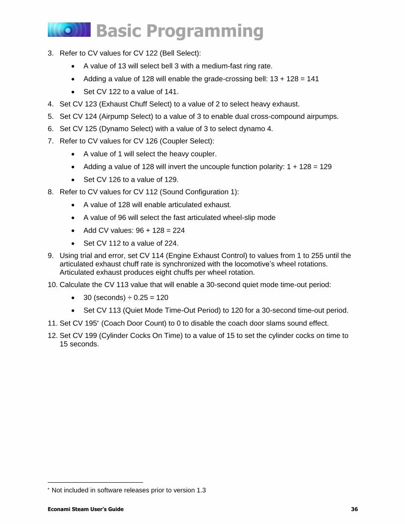
Basic Programming
Econami Steam User’s Guide 36
3. Refer to CV values for CV 122 (Bell Select):
A value of 13 will select bell 3 with a medium-fast ring rate.
Adding a value of 128 will enable the grade-crossing bell: 13 + 128 = 141
Set CV 122 to a value of 141.
4. Set CV 123 (Exhaust Chuff Select) to a value of 2 to select heavy exhaust.
5. Set CV 124 (Airpump Select) to a value of 3 to enable dual cross-compound airpumps.
6. Set CV 125 (Dynamo Select) with a value of 3 to select dynamo 4.
7. Refer to CV values for CV 126 (Coupler Select):
A value of 1 will select the heavy coupler.
Adding a value of 128 will invert the uncouple function polarity: 1 + 128 = 129
Set CV 126 to a value of 129.
8. Refer to CV values for CV 112 (Sound Configuration 1):
A value of 128 will enable articulated exhaust.
A value of 96 will select the fast articulated wheel-slip mode
Add CV values: 96 + 128 = 224
Set CV 112 to a value of 224.
9. Using trial and error, set CV 114 (Engine Exhaust Control) to values from 1 to 255 until the articulated exhaust chuff rate is synchronized with the locomotive’s wheel rotations. Articulated exhaust produces eight chuffs per wheel rotation.
10. Calculate the CV 113 value that will enable a 30-second quiet mode time-out period:
30 (seconds) ÷ 0.25 = 120
Set CV 113 (Quiet Mode Time-Out Period) to 120 for a 30-second time-out period.
11. Set CV 195 (Coach Door Count) to 0 to disable the coach door slams sound effect.
12. Set CV 199 (Cylinder Cocks On Time) to a value of 15 to set the cylinder cocks on time to 15 seconds.
Not included in software releases prior to version 1.3
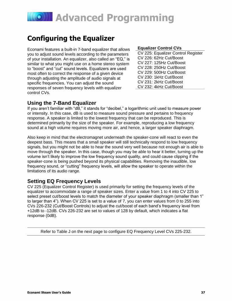
Advanced Programming
Econami Steam User’s Guide 37
Advanced Programming
Configuring the Equalizer Econami features a built-in 7-band equalizer that allows you to adjust sound levels according to the parameters of your installation. An equalizer, also called an “EQ,” is similar to what you might use on a home stereo system to “boost” and “cut” sound levels. Equalizers are used most often to correct the response of a given device through adjusting the amplitude of audio signals at specific frequencies. You can adjust the sound responses of seven frequency levels with equalizer control CVs.
Using the 7-Band Equalizer If you aren’t familiar with “dB,” it stands for “decibel,” a logarithmic unit used to measure power or intensity. In this case, dB is used to measure sound pressure and pertains to frequency response. A speaker is limited to the lowest frequency that can be reproduced. This is determined primarily by the size of the speaker. For example, reproducing a low frequency sound at a high volume requires moving more air, and hence, a larger speaker diaphragm. Also keep in mind that the electromagnet underneath the speaker-cone will react to even the deepest bass. This means that a small speaker will still technically respond to low frequency signals, but you might not be able to hear the sound very well because not enough air is able to move through the speaker. In this case, though you may be able to hear it better, turning up the volume isn’t likely to improve the low frequency sound quality, and could cause clipping if the speaker-cone is being pushed beyond its physical capabilities. Removing the inaudible, low frequency sound, or “cutting” frequency levels, will allow the speaker to operate within the limitations of its audio range.
Setting EQ Frequency Levels CV 225 (Equalizer Control Register) is used primarily for setting the frequency levels of the equalizer to accommodate a range of speaker sizes. Enter a value from 1 to 4 into CV 225 to select preset cut/boost levels to match the diameter of your speaker diaphragm (smaller than 1” to larger than 4”). When CV 225 is set to a value of 7, you can enter values from 0 to 255 into CVs 226-232 (Cut/Boost Controls) to adjust the cut/boost of each band’s frequency level from +12dB to -12dB. CVs 226-232 are set to values of 128 by default, which indicates a flat response (0dB).
Refer to Table J on the next page to configure EQ Frequency Level CVs 225-232.
Equalizer Control CVs
CV 225: Equalizer Control Register CV 226: 62Hz Cut/Boost CV 227: 125Hz Cut/Boost CV 228: 250Hz Cut/Boost CV 229: 500Hz Cut/Boost CV 230: 1kHz Cut/Boost CV 231: 2kHz Cut/Boost CV 232: 4kHz Cut/Boost

Advanced Programming
Econami Steam User’s Guide 38
Table J. CV 225: EQ Control Register *Cut/boost values for CVs 226-232 shown in red
CV Value Description 62Hz
CV 226 125Hz CV 227
250Hz CV 228
500Hz CV 229
1kHz CV 230
2kHz CV 231
4kHz CV 232
0 Flat 0dB 128
0dB 128
0dB 128
0dB 128
0dB 128
0dB 128
0dB 128
1 Micro Speaker (smaller than 1”)
-12dB 0
-12dB 0
+7.12 200
+3dB 160
+1.5dB 140
+0.8dB 132
0dB 128
2 Small Speaker (1” to 2”)
-6dB 60
-3dB 96
+4.1dB 168
+3dB 160
0dB 128
0dB 128
+0.8dB 132
3 Medium Speaker (2” to 4”)
-3dB 96
+4.1dB 168
+2.3dB 148
+1.1dB 136
0dB 128
0dB 128
0dB 128
4 Large Speaker (larger than 4”)
+6dB 192
+3dB 160
+1.5dB 140
0dB 128
0dB 128
0dB 128
0dB 128
7 Custom EQ Levels +/-12dB 0-255
+/-12dB 0-255
+/-12dB 0-255
+/-12dB 0-255
+/-12dB 0-255
+/-12dB 0-255
+/-12dB 0-255
The graph below indicates the minimum-to-maximum frequency response for each band. Notice the overlap from one frequency band to the next. Keep in mind that adjusting the response with one CV will raise or lower the sounds of nearby frequencies as well.
Making adjustments while sounds are playing is the easiest way to set the EQ because you can listen to each response. Because of this, we recommend programming this feature on the mainline. Start with CV 226 and make adjustments until you’re satisfied with each band’s frequency response. Depending upon the speaker you’re using, adjusting the lowest frequency bands may have little or no effect. If this is the case, the audio frequencies are out of the speaker’s range, and we suggest that you set the CV to 0 (-12dB). Note: Setting the cut/boost levels in CVs 226-232 to values that are too high may result in poor sound responses or damage the speaker. Ensure that equalizer settings do not exceed your speaker’s power rating to avoid this.
CV Value Cut/Boost
255 +12dB
224 +9dB
192 +6dB
160 +3dB
128 0dB
96 -3dB
64 -6dB
42 -9dB
0 -12dB
Advanced Programming
Econami Steam User’s Guide 39
Configuring Dynamic Digital Exhaust Dynamic Digital Exhaust (DDE) allows Econami to automatically regulate sound effects during operation in response to the throttle setting. With acceleration and deceleration rates set to non-zero values and DDE properly configured, the timbre and volume of the Auto-Exhaust and side rod clank will be characteristic to the throttle setting. Because locomotives and installations vary, you may need to adjust the DDE default settings to fit your situation. This section will guide you through programming DDE CVs so that you can fine-tune your operation. Note: To access Indexed CV Page 2 with CVs 257-512, CV 31 (CV Index 1) must be set to a value of 16 (default) and CV 32 (CV Index 2) must be set to a value of 2. CV 3 (Baseline Acceleration Rate) and CV 4 (Baseline Deceleration Rate) must be programmed to some nominal value. Otherwise, the throttle setting will instantly determine the locomotive’s speed, and the DDE will lack the range needed to noticeably simulate the change in exhaust when accelerating and decelerating to a desired speed step.
Adjusting DDE Sensitivity Levels CV 2.511 (DDE Throttle Sensitivity) is used to adjust the correlation between the throttle setting and the exhaust chuff sound effect. Simply put, when the throttle setting is much greater than the current locomotive speed, the load is very high. Conversely, when the throttle is much less than the current locomotive speed, the load is very low. As such, the DDE processor modifies the timbre and volume of sound effects in response to the throttle only when acceleration and deceleration rates are set in CV 3 (Baseline Acceleration Rate) and CV 4 (Baseline Deceleration Rate). You may enter a value from 0 to 255 into CV 2.511 to adjust the DDE throttle sensitivity level. Entering a value of 0 into CV 2.511 will disable DDE throttle sensing. Setting CV 2.511 to 255 indicates that the cadence and volume of the exhaust chuff sound effect will be most sensitive to the changes in throttle setting.
Adjusting DDE Volume Limits CV 2.505 (DDE Side Rod Clank Low Volume Limit), CV 2.506 (DDE Side Rod Clank High Volume Limit), CV 2.507 (DDE Exhaust Low Volume Limit), and CV 2.508 (DDE Exhaust High Volume Limit) are used to set low and high volume limits for the side rod clank and exhaust chuff sound effects that fluctuate according to the load sensed by the DDE processor. Rather than merely adjusting the volume level, adjusting CVs 2.505-2.508 allows you to attenuate and boost the sound of the exhaust and side rod clank from each effect’s mixer channel volume level. CV 2.506 and CV 2.507 are used to specify the side rod and exhaust sound response at low loads. CV 2.505, the side rod clank low volume limit, and CV 2.508, the exhaust high volume limit, are used to specify the sound response at high loads. During acceleration and when the locomotive is operating under high loads, CV 2.508 will determine the maximum boost in exhaust volume and CV 2.505 will determine the maximum reduction in rod clank volume. A value from 0 to 255 may be programmed into each CV. Under very high loads, the exhaust volume will be amplified by +12dB when CV 2.508 is set to 255 and the rod clank volume will be attenuated by -12dB when CV 2.505 is set to 255. A value of 0
Dynamic Digital Exhaust Control CVs
CV 2.505: DDE Side Rod Clank Low Volume Limit CV 2.506: DDE Side Rod Clank High Volume Limit CV 2.507: DDE Exhaust Low Volume Limit CV 2.508: DDE Exhaust High Volume Limit CV 2.509: DDE Attack Time Constant CV 2.510: DDE Release Time Constant CV 2.511: DDE Throttle Sensitivity

Advanced Programming
Econami Steam User’s Guide 40
indicates sound volume will not be adjusted in response to throttle increases. During deceleration and when the locomotive is operating under very low loads, CV 2.507 determines the maximum attenuation in exhaust volume and CV 2.506 will determine the maximum boost in side rod clank volume. Under very low load levels, the rod clank volume will be amplified by +12dB when CV 2.506 is set to 255 and the exhaust volume will be reduced by -12dB when CV 2.507 is set to 255. In summary, CVs 2.505-2.508 allow you to adjust each sound effect’s low and high volume limits to match your preference. For instance, setting CV 2.507 to a value of 64 and CV 2.508 to a value of 255 will make the exhaust 12 dB louder during acceleration and under very high loads, but will only attenuate it by 3dB during deceleration. You can try this with the side rod clank volume as well by programming CVs 2.505 and 2.506 with the same values.
Adjusting DDE Time Constants CV 2.509 (DDE Attack Time Constant) and CV 2.510 (DDE Release Time Constant) are used to determine how quickly the DDE processor reacts to changes in load and speed. CV 2.509 determines the duration of time that elapses from when the decoder receives a new throttle command (or senses a change in load) to the time the DDE processor begins to reshape the audio signal. CV 2.510 determines the duration of time that elapses between changes in the way the DDE processor reshapes the audio signal based upon increasing or decreasing throttle commands or changes in load. Entering a value from 1 to 255 into CVs 2.509 and 2.510 will adjust the DDE attack and release time constants from minimum to maximum. Entering a value of 0 into CVs 2.509 and 2.510 will set both DDE time constants to an “instant” response.
Example: Adjusting DDE We suggest you start configuring the DDE by setting the following CVs:
1. Set CVs 3 and 4 each to 40 to enable acceleration and deceleration rates.
Note: The value suggested for CVs 3 and 4 is provided for demonstration only. You may reprogram CV 3 and CV 4 at any time to fit your preferences.
2. Set CVs 2.511 to 0 to disable DDE throttle sensing.
3. Place your locomotive on a section of track that will allow the decoder enough time to accelerate to full speed. A set of stationary test track rollers is ideal for this.
4. Increase the throttle to the maximum setting and listen to the volume and tone of the exhaust chuff.
5. Decrease the throttle and bring the locomotive to a complete stop.
6. Set CV 2.511 to a value of 100 to re-enable DDE.
7. Increase the throttle to speed-step 40. As the locomotive accelerates to match the throttle setting, you should notice the elevated volume and the heavier, deeper tone of the exhaust chuff to simulate the engine working to build speed.
8. When the locomotive reaches the throttle setting, the exhaust chuff will return to its normal volume and tone.
9. Quickly set the throttle to zero.
10. As the locomotive speed decreases, the exhaust chuff’s volume and bass-level will recede into the background as the side rod clank’s volume is heightened.

Advanced Programming
Econami Steam User’s Guide 41
Configuring Function Mapping Function mapping CVs allow you to reassign any effect to any function key, enable effects to respond automatically to direction and movement changes, map an effect to the emergency stop button, and gives you the option of using NMRA “Legacy” function mapping. It’s easy to customize function assignments to fit any operating preference with Flex-Map function mapping technology! Note: To access Indexed CV Page 1 with CVs 257-512, CV 31 (CV Index 1) must be set to a value of 16 (default) and CV 32 (CV Index 2) must be set to a value of 1 (default).
Function Mapping with Flex-Map Technology To complement the decoder’s wide range of effects, Econami puts you in control of all function assignments. Flex-Map CVs determine default function assignments for Econami, and allow you to customize function keys and effects according to a simple and versatile format.
Customize Function Assignments CVs 1.257-1.384 (Effect Map Registers) are used for function mapping. Each effect corresponds to a CV. The value of each CV determines the F0-F28 function key used to control that effect. Follow the steps below to use CVs 1.257-1.384 for customizing function assignments:
1. Ensure CV 31 (CV Index 1) is set to a value of 16.
2. Enter a value of 1 into CV 32 (CV Index 2) to select Index CV Page 1 as the active indexed CV page and enable access to CVs 1.257-1.384.
3. Access CVs 257-384 from your command station.
4. Enter a value from 0 to 28 into CVs 257-384 to map the corresponding effect to function keys F0-F28.
To completely disable (or un-map) an effect, set the corresponding effect’s CV to a value of 255.
Refer to Table K and L on the next page for a list of CVs 1.257-1.384 and corresponding effects.
Function Mapping CVs
CV 31: CV Index 1 CV 32: CV Index 2 CVs 33-46: Function Status CVs CV 57: Forward Direction Enable CV 58: Reverse Direction Enable CVs 1.257-1.385: Effect Map Registers CVs 1.385-1.512: Effect Auxiliary Map Registers
Value = Function Key
0 = F0
1 = F1
↓
28 = F28
29-254 = Reserved
255 = Effect Disabled
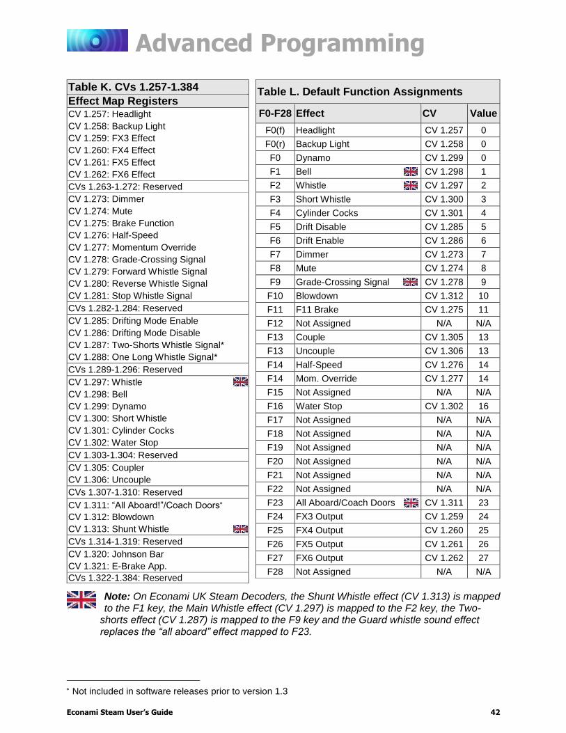
Advanced Programming
Econami Steam User’s Guide 42
Note: On Econami UK Steam Decoders, the Shunt Whistle effect (CV 1.313) is mapped to the F1 key, the Main Whistle effect (CV 1.297) is mapped to the F2 key, the Two-
shorts effect (CV 1.287) is mapped to the F9 key and the Guard whistle sound effect replaces the “all aboard” effect mapped to F23.
Not included in software releases prior to version 1.3
Table K. CVs 1.257-1.384
Effect Map Registers CV 1.257: Headlight
CV 1.258: Backup Light
CV 1.259: FX3 Effect
CV 1.260: FX4 Effect
CV 1.261: FX5 Effect
CV 1.262: FX6 Effect
CVs 1.263-1.272: Reserved
CV 1.273: Dimmer
CV 1.274: Mute
CV 1.275: Brake Function
CV 1.276: Half-Speed
CV 1.277: Momentum Override
CV 1.278: Grade-Crossing Signal
CV 1.279: Forward Whistle Signal
CV 1.280: Reverse Whistle Signal
CV 1.281: Stop Whistle Signal
CVs 1.282-1.284: Reserved
CV 1.285: Drifting Mode Enable
CV 1.286: Drifting Mode Disable
CV 1.287: Two-Shorts Whistle Signal*
CV 1.288: One Long Whistle Signal*
CVs 1.289-1.296: Reserved
CV 1.297: Whistle
CV 1.298: Bell
CV 1.299: Dynamo
CV 1.300: Short Whistle
CV 1.301: Cylinder Cocks
CV 1.302: Water Stop
CV 1.303-1.304: Reserved
CV 1.305: Coupler
CV 1.306: Uncouple
CVs 1.307-1.310: Reserved
CV 1.311: “All Aboard!”/Coach Doors
CV 1.312: Blowdown
CV 1.313: Shunt Whistle
CVs 1.314-1.319: Reserved
CV 1.320: Johnson Bar
CV 1.321: E-Brake App.
CVs 1.322-1.384: Reserved
Table L. Default Function Assignments
F0-F28 Effect CV Value
F0(f) Headlight CV 1.257 0
F0(r) Backup Light CV 1.258 0
F0 Dynamo CV 1.299 0
F1 Bell CV 1.298 1
F2 Whistle CV 1.297 2
F3 Short Whistle CV 1.300 3
F4 Cylinder Cocks CV 1.301 4
F5 Drift Disable CV 1.285 5
F6 Drift Enable CV 1.286 6
F7 Dimmer CV 1.273 7
F8 Mute CV 1.274 8
F9 Grade-Crossing Signal CV 1.278 9
F10 Blowdown CV 1.312 10
F11 F11 Brake CV 1.275 11
F12 Not Assigned N/A N/A
F13 Couple CV 1.305 13
F13 Uncouple CV 1.306 13
F14 Half-Speed CV 1.276 14
F14 Mom. Override CV 1.277 14
F15 Not Assigned N/A N/A
F16 Water Stop CV 1.302 16
F17 Not Assigned N/A N/A
F18 Not Assigned N/A N/A
F19 Not Assigned N/A N/A
F20 Not Assigned N/A N/A
F21 Not Assigned N/A N/A
F22 Not Assigned N/A N/A
F23 All Aboard/Coach Doors CV 1.311 23
F24 FX3 Output CV 1.259 24
F25 FX4 Output CV 1.260 25
F26 FX5 Output CV 1.261 26
F27 FX6 Output CV 1.262 27
F28 Not Assigned N/A N/A
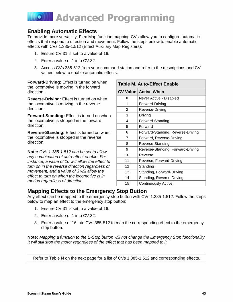
Advanced Programming
Econami Steam User’s Guide 43
Enabling Automatic Effects To provide more versatility, Flex-Map function mapping CVs allow you to configure automatic effects that respond to direction and movement. Follow the steps below to enable automatic effects with CVs 1.385-1.512 (Effect Auxiliary Map Registers):
1. Ensure CV 31 is set to a value of 16.
2. Enter a value of 1 into CV 32.
3. Access CVs 385-512 from your command station and refer to the descriptions and CV values below to enable automatic effects.
Forward-Driving: Effect is turned on when the locomotive is moving in the forward direction.
Reverse-Driving: Effect is turned on when the locomotive is moving in the reverse direction.
Forward-Standing: Effect is turned on when the locomotive is stopped in the forward direction.
Reverse-Standing: Effect is turned on when the locomotive is stopped in the reverse direction. Note: CVs 1.385-1.512 can be set to allow any combination of auto-effect enable. For instance, a value of 10 will allow the effect to turn on in the reverse direction regardless of movement, and a value of 3 will allow the effect to turn on when the locomotive is in motion regardless of direction.
Mapping Effects to the Emergency Stop Button Any effect can be mapped to the emergency stop button with CVs 1.385-1.512. Follow the steps below to map an effect to the emergency stop button:
1. Ensure CV 31 is set to a value of 16.
2. Enter a value of 1 into CV 32.
3. Enter a value of 16 into CVs 385-512 to map the corresponding effect to the emergency stop button.
Note: Mapping a function to the E-Stop button will not change the Emergency Stop functionality. It will still stop the motor regardless of the effect that has been mapped to it.
Refer to Table N on the next page for a list of CVs 1.385-1.512 and corresponding effects.
Table M. Auto-Effect Enable
CV Value Active When
0 Never Active - Disabled
1 Forward-Driving
2 Reverse-Driving
3 Driving
4 Forward-Standing
5 Forward
6 Forward-Standing, Reverse-Driving
7 Forward, Reverse-Driving
8 Reverse-Standing
9 Reverse-Standing, Forward-Driving
10 Reverse
11 Reverse, Forward-Driving
12 Standing
13 Standing, Forward-Driving
14 Standing, Reverse-Driving
15 Continuously Active

Advanced Programming
Econami Steam User’s Guide 44
Table N. CVs 1.385-1.512
Effect Auxiliary Map Registers
CV 1.385: Headlight
CV 1.386: Backup Light
CV 1.387: FX3 Effect
CV 1.388: FX4 Effect
CV 1.389: FX5 Effect
CV 1.390: FX6 Effect
CVs 1.391-1.400: Reserved
CV 1.401: Dimmer
CV 1.402: Mute
CV 1.403: F11 Brake
CV 1.404: Half-Speed
CV 1.405: Momentum Override
CV 1.406: Grade-Crossing Signal
CV 1.407: Forward Whistle Signal
CV 1.408: Reverse Whistle Signal
CV 1.409: Stop Whistle Signal
CV 1.410-1.412: Reserved
CV 1.413: Drift Disable
CV 1.414: Drift Enable
CV 1.415: Two-Shorts Whistle Signal*
CV 1.416: One Long Whistle Signal*
CVs 1.417-1.424: Reserved
CV 1.425: Whistle
CV 1.426: Bell
CV 1.427: Dynamo
CV 1.428: Short Whistle
CV 1.429: Cylinder Cocks
CV 1.430: Water Stop
CV 1.431-1.432: Reserved
CV 1.433: Couple
CV 1.434: Uncouple
CV 1.435-1.438: Reserved
CV 1.439: All Aboard/Coach Doors (Guard Whistle) CV 1.440: Blowdown
CV 1.441: Shunt Whistle* (UK Only)
CVs 1.442-1.447: Reserved
CV 1.448: Johnson Bar
CV 1.449: E-Brake App.
CVs 1.450-1.512: Reserved
Note: On Econami UK Steam Decoders CV 1.441 has been added to allow for auxiliary mapping of the shunt whistle effect. The Guard whistle sound effect replaces the “all
aboard” sound effect.
The Econami UK Steam decoder does not support any other whistle signals besides the “high-low” signal mapped with CV1.428. As no other signals can be played, CVs 1.406-1.409 cannot be mapped to a standing or driving condition.
Not included in software releases prior to version 1.3
Advanced Programming
Econami Steam User’s Guide 45
Flex-Map Examples The following examples detail using CVs 1.257-1.512 for function mapping, enabling automatic effects, and mapping an effect to the emergency stop button. Before accessing CVs 257-512, ensure CV 31 is set to a value of 16, and enter a value of 1 into CV 32.
Example: Mapping Steam Functions Adjusting CVs 1.257-1.384 (Effect Map Registers) to customize function assignments for steam locomotives is simple. Refer to Table K if needed. In this example, we will configure the grade-crossing signal and the cylinder cock functions with only two CVs:
1. We want to map the grade-crossing signal to function key F4. Set CV 1.278 to a value of 4 to map the grade-crossing signal to function key F4 (4 = F4). Now you can activate the long whistle with F2, the short whistle with F3, and the grade-crossing signal with F4.
2. Now we need to re-map the cylinder cocks (F4 by default) effect next to the blowdown function (F10 by default), program CV 1.301 to a value of 9 to map the cylinder cocks effect to function key F9 (9 = F9). This will allow you to clear the cylinders of condensed water with F9 and blow down the boiler with F10.
Example: Setting Up Automatic Signals You may want to use CVs 1.384-1.512 to enable automatic forward, reverse, and stop whistle signals. The following example details setting CV 1.407 (Forward Whistle Signal Auxiliary Map Register), CV 1.408 (Reverse Whistle Signal Auxiliary Map Register), and CV 1.409 (Stop Whistle Signal Auxiliary Map Register) to enable automatic whistle signals:
1. Enter a value of 1 into CV 407 to enable automatic forward signals when the locomotive is forward-driving.
2. Enter a value of 2 into CV 408 to enable automatic reverse signals when the locomotive is reverse-driving.
3. Enter a value of 12 into CV 409 to enable automatic stop signals when the locomotive is standing (regardless of direction).
Example: Mapping the Emergency Gyralite to the Emergency Stop Button You may want to map the emergency Gyralite to add a lighting effect to the emergency brake application effect. The following example details setting the emergency Gyralite to the FX3 lighting output, and mapping the FX3 effect to the emergency stop button:
1. Enter a value of 21 into CV 51 (FX3 Configuration) to set the emergency Gyralite to the FX3 lighting output. Refer to “Configuring Lighting Outputs” for more information.
2. Enter a value of 255 into CV 259 (FX3 Effect Map Register) to disable function control for the FX3 lighting output.
3. To map the emergency Gyralite to the emergency stop button, enter a value of 16 into CV 387 (FX3 Effect Auxiliary Map Register).
4. We want to map the grade-crossing signal to function key F4. Set CV 1.278 to a value of 4 to map the grade-crossing signal to function key F4 (4 = F4). Now you can activate the long whistle with F2, the short whistle with F3, and the grade-crossing signal with F4.
5. Now we need to re-map the cylinder cocks (F4 by default) effect next to the blowdown function (F10 by default), program CV 1.301 to a value of 9 to map the cylinder cocks effect to function key F9 (9 = F9). This will allow you to clear the cylinders of condensed water with F9 and blow down the boiler with F10.

Advanced Programming
Econami Steam User’s Guide 46
NMRA Legacy Function Mapping CVs 33-46 (Function Status CVs) are function mapping CVs stated in the NMRA Standards for DCC Configuration Variables (S-9.2.2). CVs 35-46 are used to assign effects to function keys F1-F12, and CVs 33 and 34 are used to assign effects to the F0 function key. If the same effect is selected for both reverse and forward F0 functions, that effect will turn on when the F0 function key is turned on regardless of locomotive direction. Note: CVs 33-46 are set to values of 0 by default, are a secondary method of function mapping, and are not used to determine Econami’s default function assignments. CVs 1.257-1.512 (Extended Function Mapping CVs) provide default function assignments for 28 function keys and offer comprehensive function mapping support for all of Econami’s effects in an uncomplicated and versatile format. However, mapping an effect to a function key (F0(f), F0(r), or F1-F12) using CVs 33-46 will override the corresponding function assignment mapped within CVs 1.257-1.384. As a result, the use of Legacy Function Mapping and Flex-Map Function Mapping together may produce undesirable results and is not recommended.
Table O. “Legacy” Function Output Map
Fu
ncti
on
Key
CV
HL O
utp
ut
BL O
utp
ut
Wh
istle
Bell
FX
3 O
utp
ut
FX
4 O
utp
ut
Dynam
o
Short
Wh
istle
Cylin
der
Cocks
Wate
r S
top
Dim
mer
Mute
Reserv
ed
Reserv
ed
Coup
ler
F0(f) 33 1 2 4 8 16 32 64 128
F0(r) 34 1 2 4 8 16 32 64 128
F1 35 1 2 4 8 16 32 64 128
F2 36 1 2 4 8 16 32 64 128
F3 37
1 2 4 8 16 32 64 128
F4 38 1 2 4 8 16 32 64 128
F5 39 1 2 4 8 16 32 64 128
F6 40 1 2 4 8 16 32 64 128
F7 41
1 2 4 8 16 32 64 128
F8 42 1 2 4 8 16 32 64 128
F9 43 1 2 4 8 16 32 64 128
F10 44
1 2 4 8 16 32 64 128
F11 45 1 2 4 8 16 32 64 128
F12 46 1 2 4 8 16 32 64 128
Note: On Econami UK Steam Decoders, the whistle effect is replaced with a main whistle effect and the bell effect is replaced with the shunt whistle effect.

Advanced Programming
Econami Steam User’s Guide 47
Configuring Hyperdrive2 Econami features Hyperdrive2 advanced motor control, providing high-frequency and high resolution pulse-width modulation (PWM) for silent motor control and a back-electromotive force (back-EMF) sensor to improve low-speed operation and maintain constant speeds. Load compensation and a proportional-integral (PI) control loop allows Econami to regulate motor speed in response to back-EMF measurements.
Setting Engine Recovery Speed Use CV 119 (Max Engine Recovery Speed) to designate the speed the motor will resume after momentary power losses. The recovery speed can be determined as a fixed speed step (absolute limiting) or a fraction of the throttle setting (proportional limiting). The locomotive speed will start at speed-step 0 after power losses when CV 119 is set to a value of 0 or 128. CV 119 is set to a value of 204 by default. Entering a value from 1 to 127 will designate the recovery speed as a fixed speed step from 1 to 127 (absolute limiting). If the recovery speed step in CV 119 is greater than the last speed step before power loss, the decoder will resume the throttle setting being received from the command station. Entering a value from 129 to 255 will designate the recovery speed as a fraction of the current throttle setting (proportional limiting). Higher values indicate higher speed settings. The decoder calculates the recovery speed after power losses as:
Recovery Speed = (CV 119 × Speed Step) ÷ 127
Adjusting Low-Speed Operation CV 211 (Low-Speed Compensation) is used to compensate for irregularities (if any) that occur during low-speed operation. You may enter values from 0 to 255 into CV 211 to specify the “gain value” that will be applied to the PID motor equation at low speeds. Increasing the gain value will allow the motor to operate smoother at lower speeds. When CV 211 is set to a value of 255, the effect is applied across the first nine speed steps; the gain value has a decreasing effect upon the motor as speed steps increase. This helps compensate for motors that are more difficult to start. In the event that you have an efficient motor that already spins at minimal voltages, it is possible that setting the gain value too high could elevate the locomotive’s minimum speed, and/or cause a stutter at low speeds while the control loop attempts to slow the motor. If you notice this, reduce the value of CV 211. We suggest setting CV 211 to the lowest value that will still improve low-speed operation.
Advanced Motor Control CVs
CV 10: EMF Feedback Cutout CV 119: Max Engine Recovery Speed CV 209: PID Kp Parameter CV 210: PID Ki Parameter CV 211: Low-Speed Compensation CV 212: BEMF Feedback Intensity CV 215: BEMF Reference Voltage CV 216: Motor Speed-Step Deadband CV 217: Motor Control Register
CV 119: Max Engine Recovery Speed
0 = Disabled 1 = Speed-step 1 ↓ 127 = Speed-step 127 (absolute limiting) 128 = Disabled 129 = 1% of throttle setting (proportional limiting) ↓ 255 = 100% of throttle setting (proportional limiting)

Advanced Programming
Econami Steam User’s Guide 48
Control Loop Coefficients Econami compensates for load changes in response to back-EMF voltage readings that compare motor load to locomotive speed. When a variation between them occurs, a proportional-integral (PI) control loop adjusts the motor voltage to compensate for the difference so that the locomotive’s speed remains consistent. Adjust the PI control loop with CV 209 (PID Kp Parameter) and CV 210 (PID Ki Parameter).
Kp Coefficient CV 209 is used for adjusting the proportional gain of the control loop, and compensates for dynamic changes in the motor load based on the contrast between the throttle setting and motor speed. CV 209 may be programmed with a value from 0 to 255. Higher values indicate higher levels of compensation. However, values that are too high may lead to inconsistencies in motor control.
Ki Coefficient CV 210 is used for adjusting the integral gain of the control loop, and compensates for static changes in motor load by applying a correction based on the integral difference between the throttle setting and the current motor speed. CV 210 may be set to a value from 0 to 255. Higher values indicate higher levels of compensation and a more sensitive control loop. We suggest setting CV 210 to the lowest value that still provides optimal performance; setting CV 210 to values that are too high may lead to oscillations in locomotive speed. Note: Setting CVs 209 and 210 to values of 0 will disable the control loop.
Strategy for Optimizing Hyperdrive2 Finding the right combination of CV settings requires some experimenting and patience. Be aware that these settings will inherently vary between locomotives. If you happen to make an adjustment to an advanced motor control CV that compromises operation in some way, you can reset CV settings with CV 8 (Manufacturer ID). Refer to “Introduction to Programming” for more information. Use your CV settings as starting points when configuring other locomotives. Adjusting a particular setting can actually degrade performance, and therefore changes should be made in small increments until you find your preferred result. And remember, the decoder’s default settings should provide satisfactory performance for most situations.
Example: Adjusting the Control Loop We suggest the following procedure to help fine-tune the CV settings:
1. Make sure all the Hyperdrive2 CVs are set to default values.
2. Set CV 2 (Vstart), CV 5 (Vhigh), and CV 6 (Vmid) to 0.
3. With the locomotive on level track, set the throttle to speed-step 20.
4. Increase the value of CV 209 until the locomotive’s speed becomes varied and choppy.
5. Reduce the value of CV 209 until speed is consistent, smooth, and without variance.
6. Increase the value of CV 210 until you notice the locomotive’s speed begin to oscillate.
7. Reduce the value of CV 210 until the oscillation stops.

Advanced Programming
Econami Steam User’s Guide 49
Setting the Load Compensation Curve CV 10 (EMF Feedback Cutout) and CV 212 (Back-EMF Feedback Intensity) are used to control the amount of load compensation applied to the motor across the throttle range. CV 212 can be set to a value from 0 to 255 to determine the amount of load compensation that is initially applied to the motor. A value of 0 disables load compensation altogether, while a value of 255 corresponds to 100% compensation. CV 10 determines the degree that the load compensation is reduced as the throttle speed is increased. When CV 10 is set to 0, the amount of load compensation is constant over the entire speed range, according to the value of CV 212. Setting CV 10 between 1 and 126 will determine the speed step at which the load compensation is reduced to 0. Setting CV 10 between 128 and 255 will select a partial load compensation reduction at full speed. The minimum load compensation level at speed-step 128 is calculated and illustrated as follows:
BEMF Intensity = CV 212 x (1 – (speed step ÷ CV 10) ÷ 255 In general, you will want to have full load compensation at low speeds that will gradually reduce to 0 at top speed. Set CV 10 to 126 to achieve this. When operating in a consist, you may need to reduce the value in CV 212 to reduce the low speed load compensation, and therefore avoid pitting the locomotives against each other.
BEMF Reference Voltage CV 215 (BEMF Reference Voltage) allows you to change the reference voltage for the back-EMF to match the voltage on your track. By matching the back-EMF reference voltage of the decoder with your track voltage, your locomotive will run smoother and more consistently. CV 215 may be programmed with any value from 60 to 255 to set the back-EMF reference Voltage from 6 to 25.5 volts. If you are planning to consist the model with other models equipped with SoundTraxx decoders (such as Tsunami or MC1 and MC2 DCC Mobile Decoders), make sure that the value entered in CV215 is equal to the observed voltage of the track output from your command station, so that the reference voltage is identical to your other decoders. To set this CV, simply take the observed voltage on your track and multiply it by 10 to calculate the programming value. For example, 12.5 Volts would be represented as a CV value of 125.
Setting the Motor Speed-Step Deadband* CV 216 (Motor Speed-Step Deadband) determines the speed step at which voltage is first applied to the motor to set the locomotive in motion. Entering values from 1 to 126 into CV 216 will set the motor speed-step deadband from speed-step 1 to speed-step 126. Setting CV 216 to higher values will allow the locomotive to remain stationary as the throttle is increased from zero.
* Not included in software releases prior to version 1.3

Advanced Programming
Econami Steam User’s Guide 50
Example: Motor Speed Step Deadband and Automatic Whistle Signals Refer to the following example to configure automatic forward-driving and reverse-driving whistle signals using CV 216:
1. To enable automatic forward-driving whistle signals, set CV 1.407 (Forward Whistle Signal Auxiliary Map Register) to a value of 1.
2. To enable automatic reverse-driving whistle signals, set CV 1.408 (Reverse Whistle Signal Auxiliary Map Register) to a value of 2.
3. o allow forward-driving and reverse-driving whistle signals to be issued after the throttle is increased from zero and before the locomotive begins to move, set CV 216 to a value of 3. The locomotive will begin to move at speed-step 3.
Enabling Back-EMF and Auto-Stop Back EMF is enabled by default to better regulate the operation of the motor. Disabling back-EMF control will deactivate all back-EMF regulated automatic features. Enter a value of 8 to enable auto-stop. Enabling auto-stop will bring the locomotive to a stop for 500ms before changing direction.
Advanced Programming
Econami Steam User’s Guide 51
Configuring for Advanced Consist Operation A consist is made up of several units that are coupled together to operate as a complete train. In model railroading, “Advanced Consisting” means that the decoder is used to configure the consist, instead of the command station. Consists allow an easy way for a single operator to run a multi-unit lash-up, for example. You can use advanced consist CVs to determine the decoder’s consist address, set consist acceleration and deceleration rates, enable function keys F0-F28, and configure automatic effects.
Setting the Consist Address Entering a value from 1 to 127 into CV 19 (Consist Address) will set the consist address from 1 to 127 for all units in the forward direction. Entering values from 129 to 255 into CV 19 will set the consist address from 1 to 127 for all units in the reverse direction (more common in diesel operations). Because the consist address is specific to direction, ensure all units are correctly oriented. Entering a value of 0 or 128 into CV 19 will disable the consist address. After setting the consist address, the decoder will still respond to the active primary or extended address for all commands except speed and direction data. The decoder will not recognize programing commands sent to the consist address in Operations Mode, and will only respond to programing commands sent to the decoder’s primary or extended address.
Enabling Consist Functions CV 21 (Consist Function Enable 1), CV 22 (Consist Function Enable 2), CV 245 (Consist Function Enable 3), and CV 246 (Consist Function Enable 4) allow you to enable functions for advanced consist operation when a valid consist address is active in CV 19. Note: You can enable the effects mapped to function keys in CVs 1.257-1.384 (Effect Map Registers) for advanced consist operation with CVs 21, 22, 245, and 246. Refer to “Using Econami” to default function assignments for F0-F28, and refer to “Configuring Function Mapping” to customize Flex-Map function mapping CVs.
Follow the steps on the next page to enable functions for advanced consist operation.
Advanced Consist CVs
CV 19: Consist Address CV 21: Consist Function Enable 1 CV 22: Consist Function Enable 2 CV 23: Consist Acceleration Rate CV 24: Consist Deceleration Rate CV 245: Consist Function Enable 3 CV 246: Consist Function Enable 4 CV 247: Consist Function Enable 5

Advanced Programming
Econami Steam User’s Guide 52
Consist Function Enable 1-4 The following procedure details enabling effects mapped to F0(f), F0(r), and F1-F28 for advanced consist operation:
1. Circle the CV values associated with your preferred F0-F28 function keys.
2. For each CV, add the values together and record the sum in the space provided. You should have four total CV values for enabling your preferred function keys when finished.
3. Enter each value into CVs 21, 22, 245, and 246 to enable your preferred functions for advanced consist operation.
CV 21: Consist Function Enable 1
Bit 7 Bit 6 Bit 5 Bit 4 Bit 3 Bit 2 Bit 1 Bit 0
Function F8 F7 F6 F5 F4 F3 F2 F1
CV Value 128 64 32 16 8 4 2 1
CV 21 Value = _____
CV 22: Consist Function Enable 2
Bit 7 Bit 6 Bit 5 Bit 4 Bit 3 Bit 2 Bit 1 Bit 0
Function 0 0 F12 F11 F10 F9 F0(r) F0(f)
CV Value 0 0 32 16 8 4 2 1
CV 22 Value = _____
CV 245: Consist Function Enable 3
Bit 7 Bit 6 Bit 5 Bit 4 Bit 3 Bit 2 Bit 1 Bit 0
Function F20 F19 F18 F17 F16 F15 F14 F13
CV Value 128 64 32 16 8 4 2 1
CV 245 Value = _____
CV 246: Consist Function Enable 4
Bit 7 Bit 6 Bit 5 Bit 4 Bit 3 Bit 2 Bit 1 Bit 0
Function F28 F27 F26 F25 F24 F23 F22 F21
CV Value 128 64 32 16 8 4 2 1
CV 246 Value = _____

Advanced Programming
Econami Steam User’s Guide 53
Setting Consist Momentum Rates CVs 23 (Consist Acceleration Rate) and 24 (Consist Deceleration Rate) are used to set the acceleration and deceleration rates for consists when a valid consist address is active. Like CVs 3 (Baseline Acceleration Rate) and 4 (Baseline Deceleration Rate), CVs 23 and 24 are used to determine the time it will take the consist to accelerate to full speed from a stop and come to a stop from full speed. Values from 0 to 255 may be programmed into each CV, though they are interpreted by the decoder as values from -127 to +127. Furthermore, values from 0 to 127 are interpreted as 0 to +127, whereas values from 128 to 255 are interpreted as 0 to -127. Consist acceleration and deceleration values from -127 to +127 are then added to the baseline acceleration and deceleration rates. In other words, the value of CV 23 is added to the value of CV 3 to create the consist acceleration offset, and the values of CVs 24 and 4 are added to create the consist deceleration offset. For example, if the value of CV 3 is 100, programming CV 23 with a value of 200 would adjust, or offset, the consist acceleration rate by -73, making the combined value of CVs 3 and 23 equal to 27. When the sum of CVs 23 and 3 equals 255, it will take approximately 3.8 minutes for the consist to accelerate to full speed from a complete stop. Likewise, when the sum of CVs 24 and 4 is 255, it will take 3.8 minutes to come to a complete stop from full speed. Programming values of 0 and 128 into CVs 23 and 24 will have no effect on acceleration or deceleration. Also, if the sums of CVs 23 and 3 and CVs 24 and 4 are each equal to 255, programming CVs 23 and 24 with positive values will not change the consist acceleration or deceleration rate because CV registers cannot contain values exceeding 255. Similarly, if CVs 3 and 4 are set to 0, programming CVs 23 and 24 with values from 128 to 255 (0 to -127) will have no effect because CV registers cannot contain negative values.
Enabling Consist Automatic Effects To provide more versatility, CV 247 (Consist Function Enable 5) can be used in conjunction with Flex-Map function mapping CVs to allow automatic effect configuration for advanced consist operation. Automatic effects will respond to direction and movement when enabled. Table P shows the CV values for configuring effects to respond according to the following circumstances:
Forward-Driving: Effect is turned on when the consist is moving in the forward direction.
Reverse-Driving: Effect is turned on when the consist is moving in the reverse direction.
Forward-Standing: Effect is turned on when the consist is stopped in the forward direction.
Reverse-Standing: Effect is turned on when the consist is stopped in the reverse direction. Emergency Stop: Effect is turned on when the consist receives an Emergency Stop command. Note: CV 247 can be set to allow any combination of auto-effect enable. For instance, a value of 10 will allow the effect to turn on in the reverse direction regardless of movement, and a value of 3 will allow the effect to turn on when the consist is in motion regardless of direction.
Table P. CV 247 Auto-Effect Enable
CV Value Active When
0 Never Active - Disabled
1 Forward-Driving
2 Reverse-Driving
3 Driving
4 Forward-Standing
5 Forward
6 Forward-Standing, Reverse-Driving
7 Forward, Reverse-Driving
8 Reverse-Standing
9 Reverse-Standing, Forward-Driving
10 Reverse
11 Reverse, Forward-Driving
12 Standing
13 Standing, Forward-Driving
14 Standing, Reverse-Driving
15 Continuously Active
16 Emergency Stop Button pressed

Advanced Programming
Econami Steam User’s Guide 54
Consist Example Let’s say you have a double-header consisting of two engines, shown as Nos. 4088 and 5239 below. Suppose you want to operate them as a single unit with consist address 40, meaning both engines will be consisted in the forward direction.
You will probably want to enable F8 and F11 for both units so you can mute sound effects and apply the brakes. However, you probably only want to enable the headlight, whistle, short whistle, and bell for the lead engine and enable the backup light for the trailing engine. In summary, this means enabling functions F0(f), F1, F2, F3, F8, and F11 for engine No. 4088, and enabling F0(r), F8 and F11 for engine No. 5239.
Lead Engine No. 4088:
1. Program CV 19 with a value of 40 to set the consist address.
2. Determine the CV values for CVs 21 and 22. Remember, you want to enable the bell, whistle, short whistle, and mute function using CV 21 and the headlight and F11 brake function using CV 22.
3. To enable F1, F2, F3, and F8, add the corresponding CV 21 bit values together: 1 + 2 + 4 + 128 = 135.
4. Program CV 21 with a value of 135 to enable the bell, whistle, short whistle, and mute function.
5. Do the same to enable F0(f) and F11 using CV 22: 1 + 16 = 17.
6. Program CV 22 with a value of 17 to enable the headlight and the F11 brake function.
Trailing Engine No. 5239:
1. Program CV 19 with a value of 40 to set the consist address.
2. For the trailing unit, enable the mute function using CV 21 and the backup light and brake function using CV 22.
3. To enable F8, program CV 21 with a value of 128 (total value of bit 7).
4. To enable F0(r) and F11, add the corresponding CV 22 bit values together: 2 + 16 = 18.
5. Program CV 22 with a value of 18 to enable the backup light and F11 brake function.
Table Q. Consist Example
No. 4088 Direction: Normal
No. 5239 Direction: Normal
CV 19 Value 40 CV 19 Value 40
CV 21 Value 135 CV 21 Value 128
CV 22 Value 17 CV 22 Value 18
Miscellaneous Features
Econami Steam User’s Guide 55
Miscellaneous Features
Configuring Analog Mode Operation Although Econami is designed to be operated in DCC, you can still use a conventional powerpack on a DC layout. The decoder operates entirely in response to track voltage when analog mode is enabled. Keep this in mind when configuring analog mode operation to take full advantage of the features offered by Econami. Note: Analog mode is disabled by default.
Enabling Analog Mode To enable analog mode, first enter a value of 1 into CV 12 (Alternate Power Source), then set bit 2 (APS) of CV 29 (Configuration Data 1) to 1. This will allow the decoder to receive an analog power source when a DCC signal is not available. For more information about adjusting the settings of CV 29, refer to “Configuring the Decoder.”
Operating in Analog Mode When analog mode is enabled, the decoder will be inoperative until track voltage is received from the powerpack. Increasing the throttle setting to roughly 6 Volts will deliver enough voltage to power the decoder’s internal circuitry and activate automatic sound effects while the locomotive is stopped. Increasing the throttle setting to roughly 8 Volts will set the locomotion in motion. You may use the throttle to control locomotive speed from this point. Keep in mind that you can only change direction when the locomotive is stopped. To improve low-voltage operation, the decoder automatically adjusts motor processes and sound effect volume in response to back-EMF voltage measurements to compensate for changes in motor load. Refer to “Configuring Hyperdrive2” for more information about motor control. Note: Do not exceed the input voltage rating of the decoder as stated on the product packaging. This will permanently damage the decoder! Decrease the throttle setting to zero immediately if this occurs. Refer to “Troubleshooting” to view each error code.
Enabling Analog Mode Functions When operating in analog mode, the effects mapped to function keys F0-F28 will turn on automatically when track voltage is received, and will stay on until track voltage is removed. CV 13 (Analog Mode Function Enable 1), CV 14 (Analog Mode Function Enable 2), CV 241 (Analog Mode Function Enable 3), and CV 242 (Analog Mode Function Enable 4) allow you to enable functions in analog mode. The decoder will automatically turn on all functions enabled for analog mode when track voltage is received. Note: You can enable the effects mapped to function keys in CVs 1.257-1.384 (Effect Map Registers) for analog mode operation with CVs 13, 14, 241, and 242. Refer to “Using Econami” to default function assignments for F0-F28, and refer to “Configuring Function Mapping” to customize Flex-Map function mapping CVs.
Follow the steps on the next page to enable functions for analog mode operation.
Analog Mode CVs
CV 12: Alternate Power Source CV 13: Analog Mode Function Enable 1 CV 14: Analog Mode Function Enable 2 CV 29: Configuration Data 1 CV 218: Analog Mode Motor Start Voltage CV 219: Analog Mode Engine Start Voltage CV 241: Analog Mode Function Enable 3 CV 242: Analog Mode Function Enable 4 CV 243: Analog Mode Function Enable 5
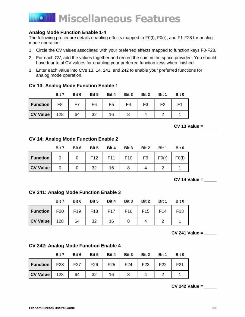
Miscellaneous Features
Econami Steam User’s Guide 56
Analog Mode Function Enable 1-4 The following procedure details enabling effects mapped to F0(f), F0(r), and F1-F28 for analog mode operation:
1. Circle the CV values associated with your preferred effects mapped to function keys F0-F28.
2. For each CV, add the values together and record the sum in the space provided. You should have four total CV values for enabling your preferred function keys when finished.
3. Enter each value into CVs 13, 14, 241, and 242 to enable your preferred functions for analog mode operation.
CV 13: Analog Mode Function Enable 1
Bit 7 Bit 6 Bit 5 Bit 4 Bit 3 Bit 2 Bit 1 Bit 0
Function F8 F7 F6 F5 F4 F3 F2 F1
CV Value 128 64 32 16 8 4 2 1
CV 13 Value = _____
CV 14: Analog Mode Function Enable 2
Bit 7 Bit 6 Bit 5 Bit 4 Bit 3 Bit 2 Bit 1 Bit 0
Function 0 0 F12 F11 F10 F9 F0(r) F0(f)
CV Value 0 0 32 16 8 4 2 1
CV 14 Value = _____
CV 241: Analog Mode Function Enable 3
Bit 7 Bit 6 Bit 5 Bit 4 Bit 3 Bit 2 Bit 1 Bit 0
Function F20 F19 F18 F17 F16 F15 F14 F13
CV Value 128 64 32 16 8 4 2 1
CV 241 Value = _____
CV 242: Analog Mode Function Enable 4
Bit 7 Bit 6 Bit 5 Bit 4 Bit 3 Bit 2 Bit 1 Bit 0
Function F28 F27 F26 F25 F24 F23 F22 F21
CV Value 128 64 32 16 8 4 2 1
CV 242 Value = _____
Miscellaneous Features
Econami Steam User’s Guide 57
Enabling Analog Mode Automatic Effects To provide more versatility, CV 243 (Analog Mode Function Enable 5) can be used in conjunction with Flex-Map function mapping CVs to allow automatic effect configuration for analog mode operation. Automatic effects will respond to direction and movement when enabled. Table R shows the CV values for configuring effects to respond according to the following circumstances:
Forward-Driving: Effect is turned on when the locomotive is moving in the forward direction.
Reverse-Driving: Effect is turned on when the locomotive is moving in the reverse direction.
Forward-Standing: Effect is turned on when the locomotive is stopped in the forward direction.
Reverse-Standing: Effect is turned on when the locomotive is stopped in the reverse direction. Note: CV 243 can be set to allow any combination of auto-effect enable. For instance, a value of 10 will allow the effect to turn on in the reverse direction regardless of movement, and a value of 3 will allow the effect to turn on when the locomotive is in motion regardless of direction.
Set the Analog Mode Start Voltage CV 218 (Analog Mode Motor Start Voltage) can be used to set the track voltage level at which power is applied to the motor to avoid the “motor-boating” effects that sometimes occur when using marginal powerpacks. Entering a value of 0 into CV 218 will set the starting voltage to 6V. Entering a value of 255 into CV 218 will set the starting voltage to the maximum setting. Set CV 218 to the lowest value that still achieves desired results. The motor will not start when the voltage level in CV 218 is set to an excessively high value. Note: Starting the motor at too low a voltage can cause the voltage from the powerpack to sag, resulting in a condition where the decoder loses power when attempting to power the motor.
Starting Voltage = (CV 218 ÷ 10) + 6V
Set the Analog Mode Engine Start Voltage CV 219 is used to adjust the voltage level applied to activate engine exhaust sound effects in analog mode. The engine exhaust start Voltage is calculated as a fraction of the minimum voltage required to power the decoder (6V). Starting Voltage is calculated as:
Starting Voltage = (CV 219 ÷ 10) + 5V Entering a value of 0 into CV 219 will set the engine exhaust start Voltage level to 6V. Entering a value of 255 into CV 219 will set the engine exhaust start voltage level to the maximum setting CV 218 (Analog Mode Motor Start Voltage) determines the voltage level applied to start the motor in analog mode. Set CV 218 to a value greater than the value of CV 219 to ensure engine exhaust sound effects are activated prior to motor start.
Table R. CV 243 Auto-Effect Enable
CV Value Active When
0 Never Active – Disabled
1 Forward-Driving
2 Reverse-Driving
3 Driving
4 Forward-Standing
5 Forward
6 Forward-Standing, Reverse-Driving
7 Forward, Reverse-Driving
8 Reverse-Standing
9 Reverse-Standing, Forward-Driving
10 Reverse
11 Reverse, Forward-Driving
12 Standing
13 Standing, Forward-Driving
14 Standing, Reverse-Driving
15 Continuously Active

Miscellaneous Features
Econami Steam User’s Guide 58
Note: Econami preforms better in analog mode when a higher quality, electronically regulated powerpack is used to supply filtered DC power. Using older rheostat-style or pulse powerpacks will make operation erratic and should not be used to power Econami-equipped installations in analog mode. If your powerpack has a pulse power switch, make sure that it is turned off.
Operating With a CurrentKeeper™ Your Econami has been designed to operate far more efficiently than previous generations of SoundTraxx DSDs giving you more reliable operations over dirty track, isolated frogs or other electrical imperfections than ever before. If your model has limited electrical pick-up or you desire to add more energy storage to the installation, a SoundTraxx CurrentKeeper can be used with any Econami decoder to provide added reliability. Refer to the Econami Installation Guide for more information about how to connect a CurrentKeeper to the various styles of decoders. The CurrentKeeper is designed to work with most decoder installations without the need to adjust any CVs. Occasionally, there are a few features and operating scenarios that warrant a minimal amount of programming for optimal operation. For more information including how to optimize the decoder for use with a CurrentKeeper in analog (DC) mode and how to limit the duration of operation of the model when it’s being powered by the CurrentKeeper, please refer to the “CurrentKeeper Reference” found on our website. .

Troubleshooting
Econami Steam User’s Guide 59
Troubleshooting
Sorting Out Decoder Difficulties If you have any difficulties operating your Econami Digital Sound Decoder, refer to this section first before doing anything else. We find that most problems are caused by errant CV values and can be easily corrected. We suggest you perform your diagnostics with the decoder on the programming track. If you are unable to locate the CV that is causing the problem, try resetting the CV values back to their defaults. Refer to “Resetting CVs and Starting Over” in the “Introduction to Programming” section for more information. The locomotive was running, but isn’t anymore
The decoder’s address has been accidentally changed.
CV 19 (Consist Address) has been inadvertently set.
CV 29 (Configuration Data 1) has been programmed to select other address.
CV 3 (Baseline Acceleration Rate) and/or CV 4 (Baseline Deceleration Rate) have been set to values that are too high.
Broken motor wire or track pickup wire. Tip: Check the decoder’s pilot light to confirm that track power is present. The locomotive isn’t running, and never has
Refer to the information above.
The decoder has been wired incorrectly. The locomotive is running, but isn’t producing sound
The mute function (F8 by default) is turned on.
Another function has been remapped to the mute function.
Volume control CVs (CVs 128-160) have been set to zero.
The speaker wire is broken.
The speaker needs to be replaced. The locomotive is running in a consist, but without sound and lighting
The consist functions are disabled. Refer to “Consist Function Enable” under the section “Configuring for Advanced Consist Operation” to set functions for consist operation.
The lights are alternating on and off as speed steps are changed
The decoder is set to 14 speed-step mode, while the command station is set to 28 or 128 speed-step mode.
The lights aren’t working
Refer to default function assignments to ensure that the correct button on your throttle is being pressed to activate the effect output.
The function mapping CVs have been improperly configured.
CV 64 (Master Brightness) has been set to a value of 0.
Lightbulbs or LEDs are burned-out.
If using 1.5 volt micro-bulbs, the resistor value is too large.
The lamp wires are broken.
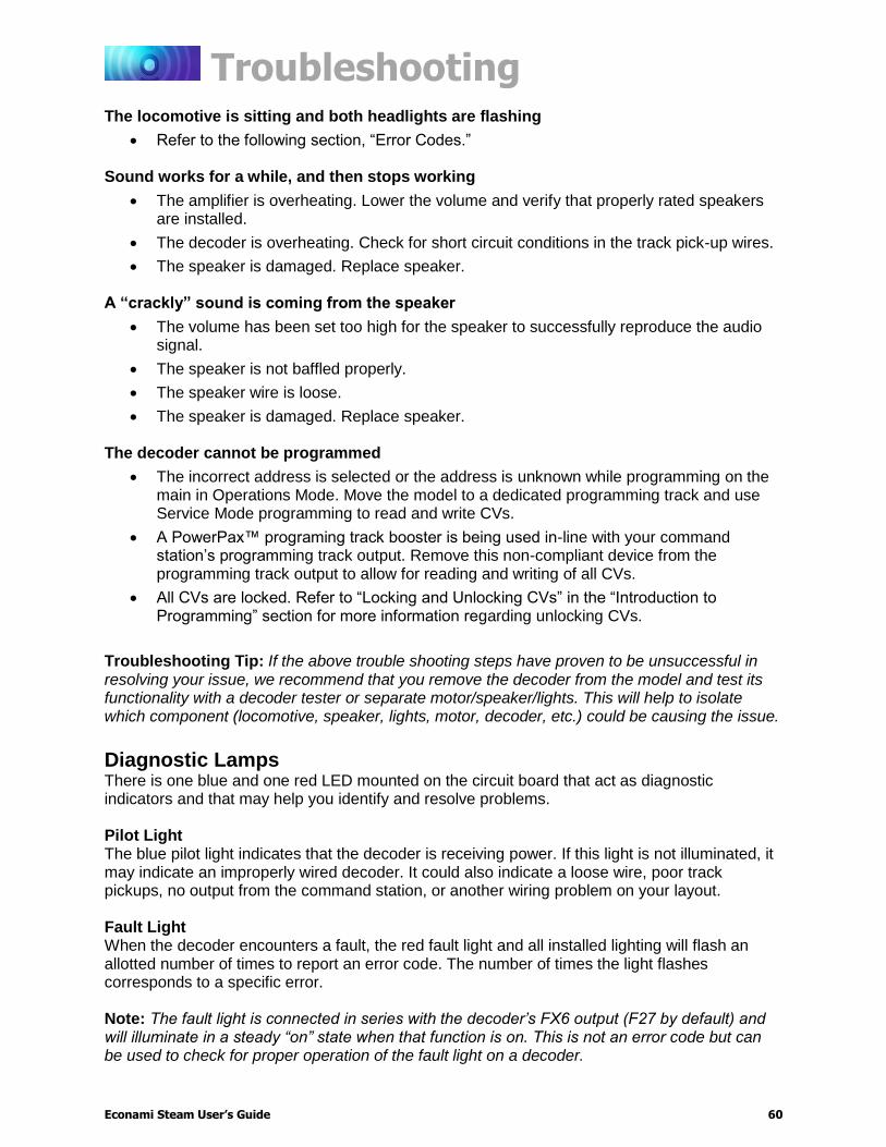
Troubleshooting
Econami Steam User’s Guide 60
The locomotive is sitting and both headlights are flashing
Refer to the following section, “Error Codes.” Sound works for a while, and then stops working
The amplifier is overheating. Lower the volume and verify that properly rated speakers are installed.
The decoder is overheating. Check for short circuit conditions in the track pick-up wires.
The speaker is damaged. Replace speaker. A “crackly” sound is coming from the speaker
The volume has been set too high for the speaker to successfully reproduce the audio signal.
The speaker is not baffled properly.
The speaker wire is loose.
The speaker is damaged. Replace speaker. The decoder cannot be programmed
The incorrect address is selected or the address is unknown while programming on the main in Operations Mode. Move the model to a dedicated programming track and use Service Mode programming to read and write CVs.
A PowerPax™ programing track booster is being used in-line with your command station’s programming track output. Remove this non-compliant device from the programming track output to allow for reading and writing of all CVs.
All CVs are locked. Refer to “Locking and Unlocking CVs” in the “Introduction to Programming” section for more information regarding unlocking CVs.
Troubleshooting Tip: If the above trouble shooting steps have proven to be unsuccessful in resolving your issue, we recommend that you remove the decoder from the model and test its functionality with a decoder tester or separate motor/speaker/lights. This will help to isolate which component (locomotive, speaker, lights, motor, decoder, etc.) could be causing the issue.
Diagnostic Lamps There is one blue and one red LED mounted on the circuit board that act as diagnostic indicators and that may help you identify and resolve problems. Pilot Light The blue pilot light indicates that the decoder is receiving power. If this light is not illuminated, it may indicate an improperly wired decoder. It could also indicate a loose wire, poor track pickups, no output from the command station, or another wiring problem on your layout. Fault Light When the decoder encounters a fault, the red fault light and all installed lighting will flash an allotted number of times to report an error code. The number of times the light flashes corresponds to a specific error. Note: The fault light is connected in series with the decoder’s FX6 output (F27 by default) and will illuminate in a steady “on” state when that function is on. This is not an error code but can be used to check for proper operation of the fault light on a decoder.

Troubleshooting
Econami Steam User’s Guide 61
Error Codes Error codes indicate problems that are easily solved. The decoder’s error codes are shown below for reference. Error 10: Over-Voltage Fault Voltage is monitored during normal operation to automatically deactivate sound and motor processes when voltage exceeds the decoder’s voltage limit. Settings resume when the voltage is reduced to within limits and will vary between decoder models. Note: The decoder’s absolute maximum voltage input varies with decoder model, generally between 22 and 27 volts! Refer to the decoder’s packaging for actual voltage limits as exceeding these limits may cause permanent damage to the decoder. Error 12: Motor Overload Fault The motor current is monitored during normal operation to automatically deactivate motor processes when the current exceeds the decoder’s rating. Power is returned to the motor after 100ms. The motor remains inactive if current-overload persists. Error 16: CV Reset This code indicates that a CV reset has occurred and all settings have been reset to default. Additional Error Codes Although rare, the decoder may also report the following error codes, which cannot be remedied by the user and require factory repair:
Error 5: EEROM Checksum Failure Error 6: EEROM Data Integrity Failure
If you’re still having difficulties, please contact our customer service department:
SoundTraxx Customer Support Center 141 Burnett Drive
Durango, CO 81301, USA Phone: (970) 259-0690
Email: [email protected] Monday-Friday, from 9am to 5:30pm (Mountain Time).

Appendix A:
Decimal-Hex-Binary Conversions
Econami Steam User’s Guide 62
Appendix A: Decimal-Hex-Binary Conversions

Appendix B: Steam Econami CV Reference
Econami Steam User’s Guide 63
Appendix B: Steam Econami CV Reference Primary CVs Sound Control CVs
CV 1: Primary Address CV 112: Sound Configuration 1
CV 2: Vstart CV 113: Quiet Mode Time-Out Period
CV 3: Baseline Acceleration Rate CV 114: Engine Exhaust Control CV 4: Baseline Deceleration Rate CV 117: F11 Brake Rate
CV 5: Vhigh CV 119: Max Engine Recovery Speed
CV 6: Vmid CV 120: Whistle Select CV 7: Manufacturer Version (Read-Only) CV 121: Alternate Whistle Select CV 8: Manufacturer ID CV 122: Bell Select CV 10: EMF Feedback Cutout CV 123: Exhaust Chuff Select CV 11: Packet Time-Out Value CV 124: Airpump Select CV 12: Alternate Power Source CV 125: Dynamo Select CV 13: Analog Mode Function Enable 1 CV 126: Coupler Select CV 14: Analog Mode Function Enable 2 CV 128: Master Volume
CV 15: CV Unlock Code CVs 129-150: Mixer Channel Volume Control CV 16: CV Lock ID CV 193: Auto-Bell On Set Point CVs 17-18: Extended Address CV 194: Auto-Bell On Time
CV 19: Consist Address CV 195: Coach Door Count CV 21: Consist Function Enable 1 CV 196: Brake Squeal Sensitivity
CV 22: Consist Function Enable 2 CV 197: Analog Mode Auto-Sound Enable
CV 23: Consist Acceleration Rate CV 198: DCC Mode Auto-Sound Enable
CV 24: Consist Deceleration Rate CV 199: Cylinder Cocks On Time
CV 25: Speed Table Enable Advanced Motor Control CVs
CV 29: Configuration Data 1 CV 209: PID Kp Parameter CV 30: Error Information CV 210: PID Ki Parameter CV 31: CV Index 1 (Read-Only) CV 211: Low-Speed Compensation
CV 32: CV Index 2 CV 212: BEMF Feedback Intensity
CV 33: F0(f) Output Location CV 213: BEMF Sample Period
CV 34: F0(r) Output Location CV 214: BEMF Sample Aperture Time
CV 35: F1 Output Location CV 215: BEMF Reference Voltage
CV 36: F2 Output Location CV 216: Motor Speed Step Deadband CV 37: F3 Output Location CV 217: Motor Control Register CV 38: F4 Output Location CV 218: Analog Mode Motor Start Voltage
CV 39: F5 Output Location CV 219: Analog Mode Engine Start Voltage*
CV 40: F6 Output Location 7-Band Equalizer CVs
CV 41: F7 Output Location CV 225: Equalizer Control Register CV 42: F8 Output Location CVs 226-232: Cut/Boost Controls
CV 43: F9 Output Location Analog Function Enable CVs
CV 44: F10 Output Location CV 241: Analog Mode Function Enable 3
CV 45: F11 Output Location CV 242: Analog Mode Function Enable 4
CV 46: F12 Output Location CV 243: Analog Mode Function Enable 5
Lighting Effect CVs Consist Function Enable CVs
CV 49: Headlight Effect Select CV 245: Consist Function Enable 3
CV 50: Backup Light Effect Select CV 246: Consist Function Enable 4
CV 51-54: FX3-FX6 Effect Select CV 247: Consist Function Enable 5
CV 57: Forward Direction Enable Index Page 1: Extended Function Mapping CVs
CV 58: Reverse Direction Enable CVs 1.257-1.384: Effect Map Registers CV 59: Hyperlight Flash Rate CVs 1.385-1.512: Effect Auxiliary Map Registers
CV 60: Grade-Crossing Hold Time Index Page 2: DDE Control CVs
CV 61: Brightness Register 1 CV 2.505: DDE Side Rod Clank Low Volume Limit CV 62: Brightness Register 2 CV 2.506: DDE Side Rod Clank High Volume Limit CV 63: Dimmer Level CV 2.507: DDE Exhaust Low Volume Limit
Speed Table CVs CV 2.508: DDE Exhaust High Volume Limit
CV 66: Forward Motor Trim CV 2.509: DDE Attack Time Constant CVs 67-94: Custom Speed Table CV 2.510: DDE Release Time Constant CV 95: Reverse Motor Trim CV 2.511: DDE Throttle Sensitivity
User Information CVs
CV 105: User Identifier 1
CV 106: User Identifier 2
Not included in software releases prior to version 1.3

Appendix C: License Agreement
Econami Steam User’s Guide 64
Appendix C: License Agreement Please read this license agreement carefully before opening the package that contains the Econami Digital Sound Decoder. Breaking the seal on the package indicates your acceptance of these license terms. If you have received the Econami Digital Sound Decoder pre-installed from your dealer, then use of the product indicates your acceptance of the agreement. If you do not agree with the terms, you should return the package unopened to the dealer from whom you received the package within thirty (30) days and your money will be refunded.
SoundTraxx Software License Agreement SoundTraxx provides the computer software/firmware embedded within the Econami Digital Sound Decoder and any modifications, updates, revisions or enhancements received by you from SoundTraxx or its dealers and licenses its use within the terms set below: A. You are granted a nonexclusive, nontransferable license to use the software/firmware
included with your Econami sound system only with the Econami sound system hardware that you purchased.
B. Title and ownership of the software/firmware, sound recordings, documentation and
accompanying materials, if any, and all associated intellectual property rights remain with SoundTraxx.
C. The structure, organization, and code of the software/firmware are the valuable properties of
SoundTraxx. You may not make copies of the hardware, software/firmware, code, or any portions thereof. You are not to modify, adapt, translate, reverse engineer, de-compile, disassemble or create derivative works based on the hardware or software/firmware.
D. Unauthorized copying of the software/firmware or documentation, or failure to comply with
the above restrictions, will result in automatic termination of this Agreement. This Agreement does not grant you any intellectual property rights.

Appendix D: Service and Warranty Policy
Econami Steam User’s Guide 65
Appendix D: Service and Warranty Policy
90-Day Safety-Net Service Warranty All SoundTraxx Digital Sound Decoders are tested thoroughly during production and are warranted to be operational and free of manufacturing defects before shipment. However, in the event an error occurs during installation, SoundTraxx will cover the repair under the conditions of our Safety-Net Service Warranty. If you damage the Digital Sound Decoder or it fails to operate within the first ninety (90) days, SoundTraxx will repair or replace the product free-of-charge under the following conditions: A. The original sales receipt confirming purchase from an authorized SoundTraxx dealer must
accompany the product. The date-of-purchase shown on the receipt must be within the last 90 days. SoundTraxx will return the original receipt with your repaired unit.
B. The product must show no signs of damage of which resulted from unauthorized repairs or
modifications. This includes, but is not limited to:
Removal of the shrink tubing from the decoder
Drilled or enlarged circuit board holes
A cut or trimmed circuit board C. The Digital Sound Decoder must be returned properly packaged and insured, with postage
paid; SoundTraxx is not responsible for products lost or damaged in transit.
Limits of Liability The foregoing shall constitute the sole and exclusive remedy of any owner of this product for breach of warranty including the implied warranties of merchantability and fitness. IN NO EVENT SHALL SOUNDTRAXX BE LIABLE FOR SPECIAL OR CONSEQUENTIAL DAMAGES OR FOR THE REPRESENTATIONS OF RETAIL SELLERS.
Visit www.soundtraxx.com/support to view complete warranty information.
Contacting Support Our service department is available Monday-Friday, from 9am to 5:30pm (Mountain Time).
SoundTraxx Customer Support Center
141 Burnett Drive Durango, CO 81301, USA
Phone: (970) 259-0690 Email: [email protected]

Appendix E: Declaration of Conformity
Econami Steam User’s Guide 66
Appendix E: Declaration of Conformity
Declaration of Conformity We, Throttle Up! Corp., dba SoundTraxx, 141 Burnett Drive, Durango, Colorado USA, declare in sole responsibility that the following products:
Product Description Econami Digital Sound Decoders Model Numbers ECO-100, ECO-200, ECO-PNP, ECO-21PNEM
Part Numbers 881001, 881002, 881006, 881101, 881102, 881105, 881106
comply with all relevant regulations of the following directive:
2014/30/EU Electromagnetic Compatibility (EMC Directive) and that the following harmonized standards have been applied: EN 55014-1:2006 + A1: 2009 Part 1: Emissions EN 55014-2:1997 + A2: 2008 Part 2: Immunity


![Paragon 2 Steam Technical Reference Manual1.10].pdf · Paragon 2 Steam Technical Reference Manual . 2 INTRODUCTION Introduction The Paragon 2 sound unit is a multi-function DCC decoder](https://img.dokumen.tips/doc/110x75/5b5cb9487f8b9ad21d8cbc9e/paragon-2-steam-technical-reference-110pdf-paragon-2-steam-technical-reference.jpg)