Embed Size (px)
Citation preview
Rev. H 11/14/17
Econami Digital Sound Decoder
Steam Technical Reference Software Release 1.6
Previous software versions included

Notice The information in this document is subject to change without notice. SoundTraxx (Throttle Up! Corp.) shall not be liable for technical or editorial errors or omissions contained herein, nor for incidental or consequential damage resulting from the furnishing, performance or use of this material. This document contains information protected by copyright. No part of this document may be photocopied or reproduced in any form without the prior written consent of Throttle Up! Corp. Product names mentioned herein may be trademarks and/or registered trademarks of their respective companies. SoundTraxx, Econami, Tsunami, SoundTraxx DCC, Dynamic Digital Exhaust, Auto-Exhaust, Hyperlight, Hyperdrive2, SoundCar, and Intelligent Consisting are trademarks of Throttle Up! Corp.

Contents Primary CVs ................................................................................... 6
CV 1: Primary Address .............................................................................................................................. 6 CV 2: Vstart ............................................................................................................................................... 7 CV 3: Baseline Acceleration Rate ............................................................................................................. 8 CV 4: Baseline Deceleration Rate............................................................................................................. 9 CV 5: Vhigh ............................................................................................................................................. 10 CV 6: Vmid .............................................................................................................................................. 11 CV 7: Manufacturer Version (Read-Only) ............................................................................................... 12 CV 8: Manufacturer ID ............................................................................................................................ 13 CV 10: EMF Feedback Cutout ................................................................................................................ 14 CV 11: Packet Time-Out Value ............................................................................................................... 15 CV 12: Alternate Power Source .............................................................................................................. 16 CV 13: Analog Mode Function Enable 1 ................................................................................................. 17 CV 14: Analog Mode Function Enable 2 ................................................................................................. 18 CV 15: CV Unlock Code .......................................................................................................................... 19 CV 16: CV Lock ID .................................................................................................................................. 20 CVs 17-18: Extended Address ................................................................................................................ 21 CV 19: Consist Address .......................................................................................................................... 22 CV 21: Consist Function Enable 1 .......................................................................................................... 23 CV 22: Consist Function Enable 2 .......................................................................................................... 24 CV 23: Consist Acceleration Rate ........................................................................................................... 25 CV 24: Consist Deceleration Rate .......................................................................................................... 26 CV 25: Speed Table Enable .................................................................................................................... 27 CV 29: Configuration Data 1 ................................................................................................................... 28 CV 30: Error Information ......................................................................................................................... 29 CV 31: CV Index 1................................................................................................................................... 30 CV 32: CV Index 2................................................................................................................................... 31 CVs 33-46: Function Status CVs ............................................................................................................ 32 CV 33: F0(f) Output Location .................................................................................................................. 33 CV 34: F0(r) Output Location .................................................................................................................. 34 CV 35: F1 Output Location ...................................................................................................................... 35 CV 36: F2 Output Location ...................................................................................................................... 36 CV 37: F3 Output Location ...................................................................................................................... 37 CV 38: F4 Output Location ...................................................................................................................... 38 CV 39: F5 Output Location ...................................................................................................................... 39 CV 40: F6 Output Location ...................................................................................................................... 40 CV 41: F7 Output Location ...................................................................................................................... 41 CV 42: F8 Output Location ...................................................................................................................... 42 CV 43: F9 Output Location ...................................................................................................................... 43 CV 44: F10 Output Location .................................................................................................................... 44 CV 45: F11 Output Location .................................................................................................................... 45 CV 46: F12 Output Location .................................................................................................................... 46
Lighting Effect CVs ...................................................................... 47 CVs 49-54: Hyperlight Effect Select ........................................................................................................ 47 CV 57: Forward Direction Enable ............................................................................................................ 51 CV 58: Reverse Direction Enable ........................................................................................................... 52 CV 59: Hyperlight Flash Rate .................................................................................................................. 53 CV 60: Grade-Crossing Hold Time ......................................................................................................... 54 CV 61: Brightness Register 1 .................................................................................................................. 55 CV 62: Brightness Register 2 .................................................................................................................. 56 CV 63: Dimmer Level .............................................................................................................................. 57
Speed Table CVs .......................................................................... 58 CV 66: Forward Motor Trim ..................................................................................................................... 58 CVs 67-94: Custom Speed Table ........................................................................................................... 59 CV 95: Reverse Motor Trim .................................................................................................................... 60

User Information CVs .................................................................. 61 CV 105: User Identifier 1 ......................................................................................................................... 61 CV 106: User Identifier 2 ......................................................................................................................... 62
Sound Control CVs ....................................................................... 63 CV 112: Sound Configuration 1 .............................................................................................................. 63 CV 113: Quiet Mode Time-Out Period .................................................................................................... 64 CV 114: Engine Exhaust Control ............................................................................................................ 65 CV 117: F11 Brake Rate ......................................................................................................................... 66 CV 119: Max Engine Recovery Speed ................................................................................................... 67 CV 120: Whistle Select ........................................................................................................................... 68 CV 121: Auxiliary Whistle Select ............................................................................................................. 69 CV 122: Bell Select ................................................................................................................................. 70 CV 123: Exhaust Select .......................................................................................................................... 71 CV 124: Airpump Select .......................................................................................................................... 72 CV 125: Dynamo Select .......................................................................................................................... 73 CV 126: Coupler Select ........................................................................................................................... 74 CV 128: Master Volume .......................................................................................................................... 75 CVs 129-150: Mixer Channel Volume Control ........................................................................................ 76 CV 193: Auto-Bell On Set Point .............................................................................................................. 77 CV 194: Auto-Bell On Time ..................................................................................................................... 78 CV 195: Coach Door Count .................................................................................................................... 79 CV 196: Brake Squeal Sensitivity ........................................................................................................... 80 CV 197: Analog Mode Auto-Sound Enable ............................................................................................. 81 CV 198: DCC Mode Auto-Sound Enable ................................................................................................ 82 CV 199: Cylinder Cocks On Time ........................................................................................................... 83
Advanced Motor Control CVs ....................................................... 84 CVs 209-218: Advanced Motor Control Registers .................................................................................. 84 CV 209: PID Kp Parameter ..................................................................................................................... 84 CV 210: PID Ki Parameter ...................................................................................................................... 85 CV 211: Low-Speed Compensation ........................................................................................................ 86 CV 212: BEMF Feedback Intensity ......................................................................................................... 87 CV 213: BEMF Sample Period ................................................................................................................ 88 CV 214: BEMF Sample Aperture Time ................................................................................................... 89 CV 215: BEMF Reference Voltage ......................................................................................................... 90 CV 216: Motor Speed Step Deadband ................................................................................................... 91 CV 217: Motor Control Register .............................................................................................................. 92 CV 218: Analog Mode Motor Start Voltage ............................................................................................. 93 CV 219: Analog Mode Engine Start Voltage ........................................................................................... 94
7-Band Equalizer CVs ................................................................... 95 CV 225: Equalizer Control Register ........................................................................................................ 95 CVs 226-232: Cut/Boost Controls ........................................................................................................... 96
Analog Function Enable CVs ........................................................ 97 CV 241: Analog Mode Function Enable 3 ............................................................................................... 97 CV 242: Analog Mode Function Enable 4 ............................................................................................... 98 CV 243: Analog Mode Function Enable 5 ............................................................................................... 99
Consist Function Enable CVs ...................................................... 100 CV 245: Consist Function Enable 3 ...................................................................................................... 100 CV 246: Consist Function Enable 4 ...................................................................................................... 101 CV 247: Consist Function Enable 5 ...................................................................................................... 102
Indexed CV Page 1 .................................................................... 103 CVs 1.257-1.512: Extended Function Mapping CVs ............................................................................ 103 CVs 1.257-1.384: Effect Map Registers ................................................................................................ 105 CVs 1.385-1.512: Effect Auxiliary Map Registers ................................................................................. 106

Indexed CV Page 2 .................................................................... 107 CVs 2.505-2.511: DDE Control CVs ..................................................................................................... 107 CV 2.505: DDE Side Rod Clank Low Volume Limit .............................................................................. 107 CV 2.506: DDE Side Rod Clank High Volume Limit ............................................................................. 108 CV 2.507: DDE Exhaust Low Volume Limit .......................................................................................... 109 CV 2.508: DDE Exhaust High Volume Limit ......................................................................................... 110 CV 2.509: DDE Attack Time Constant .................................................................................................. 111 CV 2.510: DDE Release Time Constant ............................................................................................... 112 CV 2.511: DDE Throttle Sensitivity ....................................................................................................... 113

Primary CVs
Econami Steam Technical Reference 6
Primary CVs
CV 1: Primary Address
Description CV 1 is used to set the decoder’s primary address from 1 to 127.
Bit 7 Bit 0
0 A6 A5 A4 A3 A2 A1 A0
A0-A6: Primary Address 0: Reserved
Additional Information Entering values from 1 to 127 into CV 1 will set the primary address while in Service Mode. The decoder will ignore commands that attempt to program this CV with values outside the range of 1 to 127. The decoder will process all valid instruction packets addressed with the value contained in CV 1 when bit 5 of CV 29 (Configuration Data 1) is set to 0. Entering a new value into CV 1 will:
Set the value of CV 19 (Consist Address) to 0.
Clear the Extended Address Mode Enable bit in CV 29 (bit 5). Bit 5 of CV 29 must be set to 1 in order for the value of CV 1 to be changed in Operations Mode. Setting bit 5 of CV 29 back to 0 will then allow the decoder to recognize the new primary address.
Default Value: 3 Related CVs: CV 17-18 (Extended Address)
CV 19 (Consist Address) CV 29 (Configuration Data 1)
Primary CVs
Econami Steam Technical Reference 7
CV 2: Vstart
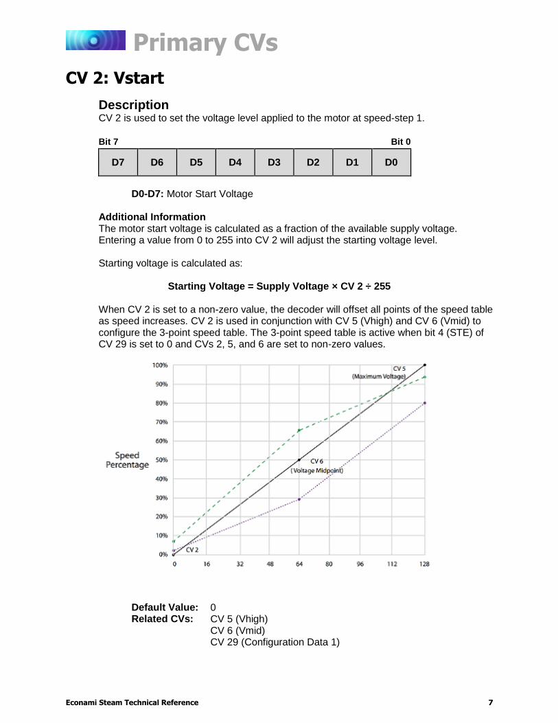
Description CV 2 is used to set the voltage level applied to the motor at speed-step 1.
Bit 7 Bit 0
D7 D6 D5 D4 D3 D2 D1 D0
D0-D7: Motor Start Voltage
Additional Information The motor start voltage is calculated as a fraction of the available supply voltage. Entering a value from 0 to 255 into CV 2 will adjust the starting voltage level. Starting voltage is calculated as:
Starting Voltage = Supply Voltage × CV 2 ÷ 255 When CV 2 is set to a non-zero value, the decoder will offset all points of the speed table as speed increases. CV 2 is used in conjunction with CV 5 (Vhigh) and CV 6 (Vmid) to configure the 3-point speed table. The 3-point speed table is active when bit 4 (STE) of CV 29 is set to 0 and CVs 2, 5, and 6 are set to non-zero values.
Default Value: 0 Related CVs: CV 5 (Vhigh)
CV 6 (Vmid) CV 29 (Configuration Data 1)
Primary CVs
Econami Steam Technical Reference 8
CV 3: Baseline Acceleration Rate
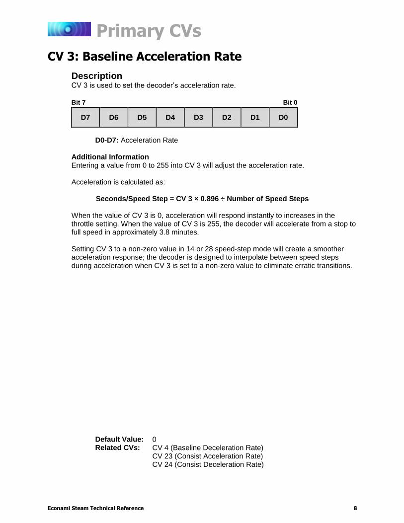
Description CV 3 is used to set the decoder’s acceleration rate.
Bit 7 Bit 0
D7 D6 D5 D4 D3 D2 D1 D0
D0-D7: Acceleration Rate
Additional Information Entering a value from 0 to 255 into CV 3 will adjust the acceleration rate. Acceleration is calculated as:
Seconds/Speed Step = CV 3 × 0.896 ÷ Number of Speed Steps When the value of CV 3 is 0, acceleration will respond instantly to increases in the throttle setting. When the value of CV 3 is 255, the decoder will accelerate from a stop to full speed in approximately 3.8 minutes. Setting CV 3 to a non-zero value in 14 or 28 speed-step mode will create a smoother acceleration response; the decoder is designed to interpolate between speed steps during acceleration when CV 3 is set to a non-zero value to eliminate erratic transitions.
Default Value: 0 Related CVs: CV 4 (Baseline Deceleration Rate)
CV 23 (Consist Acceleration Rate) CV 24 (Consist Deceleration Rate)

Primary CVs
Econami Steam Technical Reference 9
CV 4: Baseline Deceleration Rate
Description CV 4 is used to set the decoder’s deceleration rate.
Bit 7 Bit 0
D7 D6 D5 D4 D3 D2 D1 D0
D0-D7: Deceleration Rate
Additional Information Entering a value from 0 to 255 into CV 4 will adjust the deceleration rate. Deceleration is calculated as:
Seconds/Speed Step = CV 4 × 0.896 ÷ Number of Speed Steps When the value of CV 4 is 0, deceleration will respond instantly to decreases in the throttle setting. When the value of CV 4 is 255, the decoder will decelerate from full speed to a stop in approximately 3.8 minutes. Setting CV 4 to a non-zero value in 14 or 28 speed-step mode will create a smoother deceleration response; the decoder is designed to interpolate between speed steps during deceleration when CV 4 is set to a non-zero value to eliminate erratic transitions.
Default Value: 0 Related CVs: CV 3 (Baseline Acceleration Rate)
CV 23 (Consist Acceleration Rate) CV 24 (Consist Deceleration Rate) CV 117 (F11 Brake Rate)
Primary CVs
Econami Steam Technical Reference 10
CV 5: Vhigh
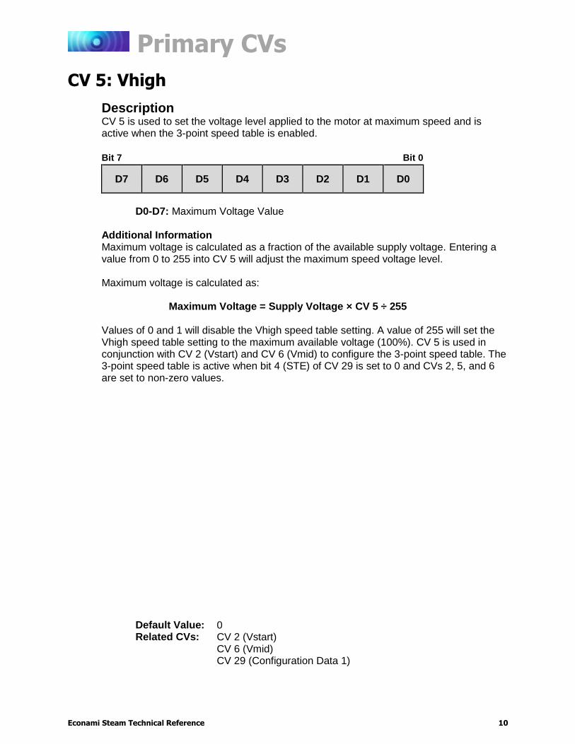
Description CV 5 is used to set the voltage level applied to the motor at maximum speed and is active when the 3-point speed table is enabled.
Bit 7 Bit 0
D7 D6 D5 D4 D3 D2 D1 D0
D0-D7: Maximum Voltage Value
Additional Information Maximum voltage is calculated as a fraction of the available supply voltage. Entering a value from 0 to 255 into CV 5 will adjust the maximum speed voltage level. Maximum voltage is calculated as:
Maximum Voltage = Supply Voltage × CV 5 ÷ 255 Values of 0 and 1 will disable the Vhigh speed table setting. A value of 255 will set the Vhigh speed table setting to the maximum available voltage (100%). CV 5 is used in conjunction with CV 2 (Vstart) and CV 6 (Vmid) to configure the 3-point speed table. The 3-point speed table is active when bit 4 (STE) of CV 29 is set to 0 and CVs 2, 5, and 6 are set to non-zero values.
Default Value: 0 Related CVs: CV 2 (Vstart)
CV 6 (Vmid) CV 29 (Configuration Data 1)
Primary CVs
Econami Steam Technical Reference 11
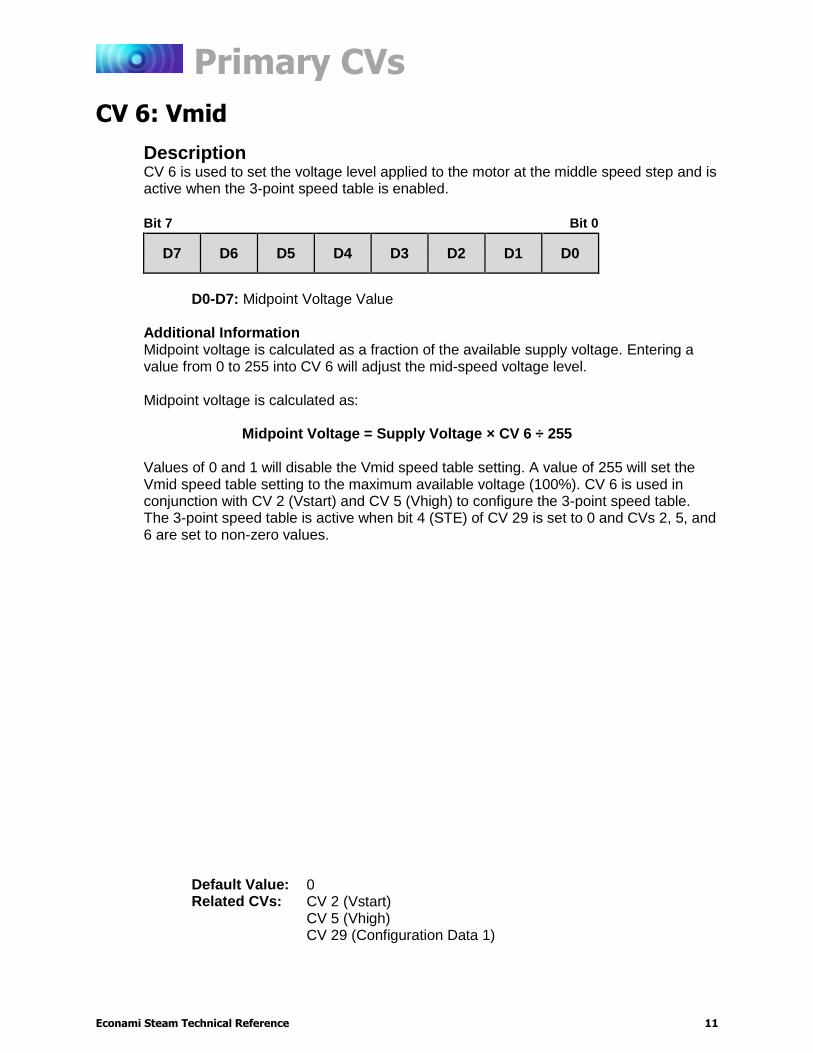
CV 6: Vmid
Description CV 6 is used to set the voltage level applied to the motor at the middle speed step and is active when the 3-point speed table is enabled.
Bit 7 Bit 0
D7 D6 D5 D4 D3 D2 D1 D0
D0-D7: Midpoint Voltage Value
Additional Information Midpoint voltage is calculated as a fraction of the available supply voltage. Entering a value from 0 to 255 into CV 6 will adjust the mid-speed voltage level. Midpoint voltage is calculated as:
Midpoint Voltage = Supply Voltage × CV 6 ÷ 255 Values of 0 and 1 will disable the Vmid speed table setting. A value of 255 will set the Vmid speed table setting to the maximum available voltage (100%). CV 6 is used in conjunction with CV 2 (Vstart) and CV 5 (Vhigh) to configure the 3-point speed table. The 3-point speed table is active when bit 4 (STE) of CV 29 is set to 0 and CVs 2, 5, and 6 are set to non-zero values.
Default Value: 0 Related CVs: CV 2 (Vstart)
CV 5 (Vhigh) CV 29 (Configuration Data 1)
Primary CVs
Econami Steam Technical Reference 12
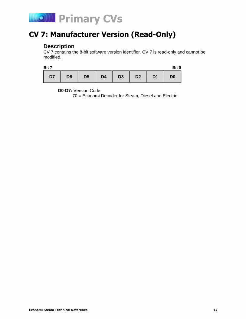
CV 7: Manufacturer Version (Read-Only)
Description CV 7 contains the 8-bit software version identifier. CV 7 is read-only and cannot be modified.
Bit 7 Bit 0
D7 D6 D5 D4 D3 D2 D1 D0
D0-D7: Version Code
70 = Econami Decoder for Steam, Diesel and Electric
Primary CVs
Econami Steam Technical Reference 13
CV 8: Manufacturer ID
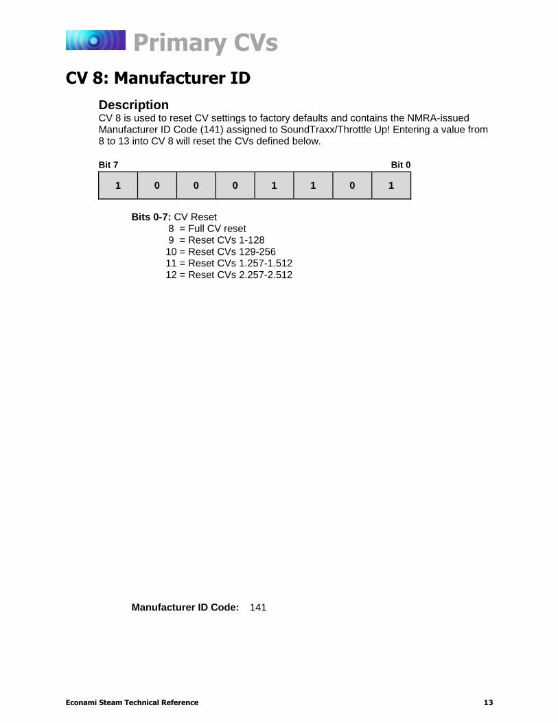
Description CV 8 is used to reset CV settings to factory defaults and contains the NMRA-issued Manufacturer ID Code (141) assigned to SoundTraxx/Throttle Up! Entering a value from 8 to 13 into CV 8 will reset the CVs defined below.
Bit 7 Bit 0
1 0 0 0 1 1 0 1
Bits 0-7: CV Reset
8 = Full CV reset 9 = Reset CVs 1-128 10 = Reset CVs 129-256 11 = Reset CVs 1.257-1.512 12 = Reset CVs 2.257-2.512
Manufacturer ID Code: 141
Primary CVs
Econami Steam Technical Reference 14
CV 10: EMF Feedback Cutout
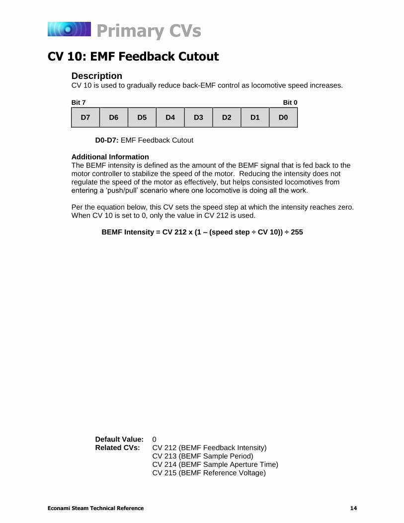
Description CV 10 is used to gradually reduce back-EMF control as locomotive speed increases.
Bit 7 Bit 0
D7 D6 D5 D4 D3 D2 D1 D0
D0-D7: EMF Feedback Cutout
Additional Information The BEMF intensity is defined as the amount of the BEMF signal that is fed back to the motor controller to stabilize the speed of the motor. Reducing the intensity does not regulate the speed of the motor as effectively, but helps consisted locomotives from entering a ‘push/pull’ scenario where one locomotive is doing all the work. Per the equation below, this CV sets the speed step at which the intensity reaches zero. When CV 10 is set to 0, only the value in CV 212 is used.
BEMF Intensity = CV 212 x (1 – (speed step ÷ CV 10)) ÷ 255
Default Value: 0 Related CVs: CV 212 (BEMF Feedback Intensity)
CV 213 (BEMF Sample Period) CV 214 (BEMF Sample Aperture Time) CV 215 (BEMF Reference Voltage)
Primary CVs
Econami Steam Technical Reference 15
CV 11: Packet Time-Out Value
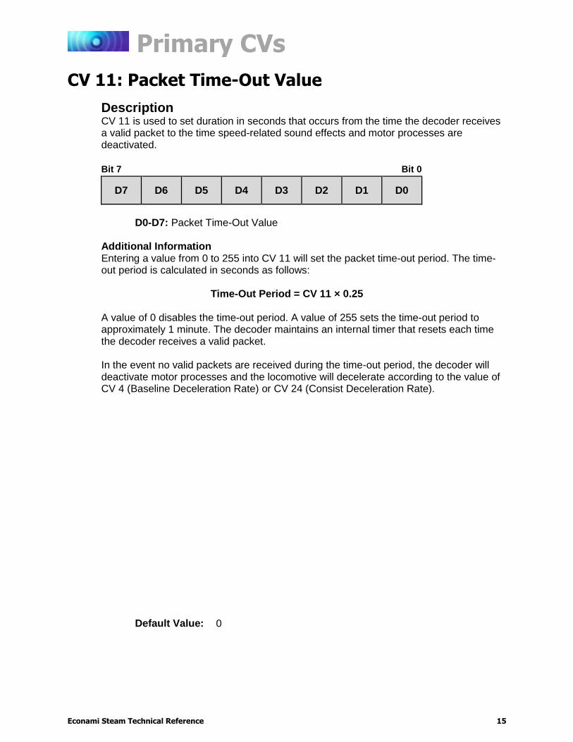
Description CV 11 is used to set duration in seconds that occurs from the time the decoder receives a valid packet to the time speed-related sound effects and motor processes are deactivated.
Bit 7 Bit 0
D7 D6 D5 D4 D3 D2 D1 D0
D0-D7: Packet Time-Out Value
Additional Information Entering a value from 0 to 255 into CV 11 will set the packet time-out period. The time-out period is calculated in seconds as follows:
Time-Out Period = CV 11 × 0.25 A value of 0 disables the time-out period. A value of 255 sets the time-out period to approximately 1 minute. The decoder maintains an internal timer that resets each time the decoder receives a valid packet. In the event no valid packets are received during the time-out period, the decoder will deactivate motor processes and the locomotive will decelerate according to the value of CV 4 (Baseline Deceleration Rate) or CV 24 (Consist Deceleration Rate).
Default Value: 0
Primary CVs
Econami Steam Technical Reference 16
CV 12: Alternate Power Source
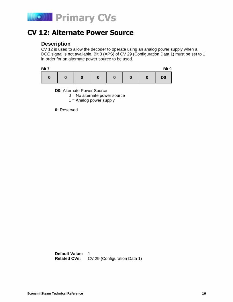
Description CV 12 is used to allow the decoder to operate using an analog power supply when a DCC signal is not available. Bit 3 (APS) of CV 29 (Configuration Data 1) must be set to 1 in order for an alternate power source to be used.
Bit 7 Bit 0
0 0 0 0 0 0 0 D0
D0: Alternate Power Source
0 = No alternate power source 1 = Analog power supply
0: Reserved
Default Value: 1 Related CVs: CV 29 (Configuration Data 1)
Primary CVs
Econami Steam Technical Reference 17
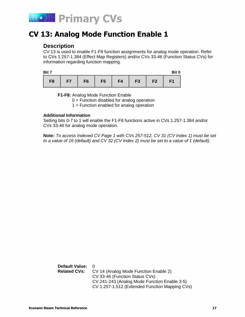
CV 13: Analog Mode Function Enable 1
Description CV 13 is used to enable F1-F8 function assignments for analog mode operation. Refer to CVs 1.257-1.384 (Effect Map Registers) and/or CVs 33-46 (Function Status CVs) for information regarding function mapping.
Bit 7 Bit 0
F8 F7 F6 F5 F4 F3 F2 F1
F1-F8: Analog Mode Function Enable
0 = Function disabled for analog operation 1 = Function enabled for analog operation
Additional Information Setting bits 0-7 to 1 will enable the F1-F8 functions active in CVs 1.257-1.384 and/or CVs 33-46 for analog mode operation. Note: To access Indexed CV Page 1 with CVs 257-512, CV 31 (CV Index 1) must be set to a value of 16 (default) and CV 32 (CV Index 2) must be set to a value of 1 (default).
Default Value: 0 Related CVs: CV 14 (Analog Mode Function Enable 2)
CV 33-46 (Function Status CVs) CV 241-243 (Analog Mode Function Enable 3-5) CV 1.257-1.512 (Extended Function Mapping CVs)
Primary CVs
Econami Steam Technical Reference 18
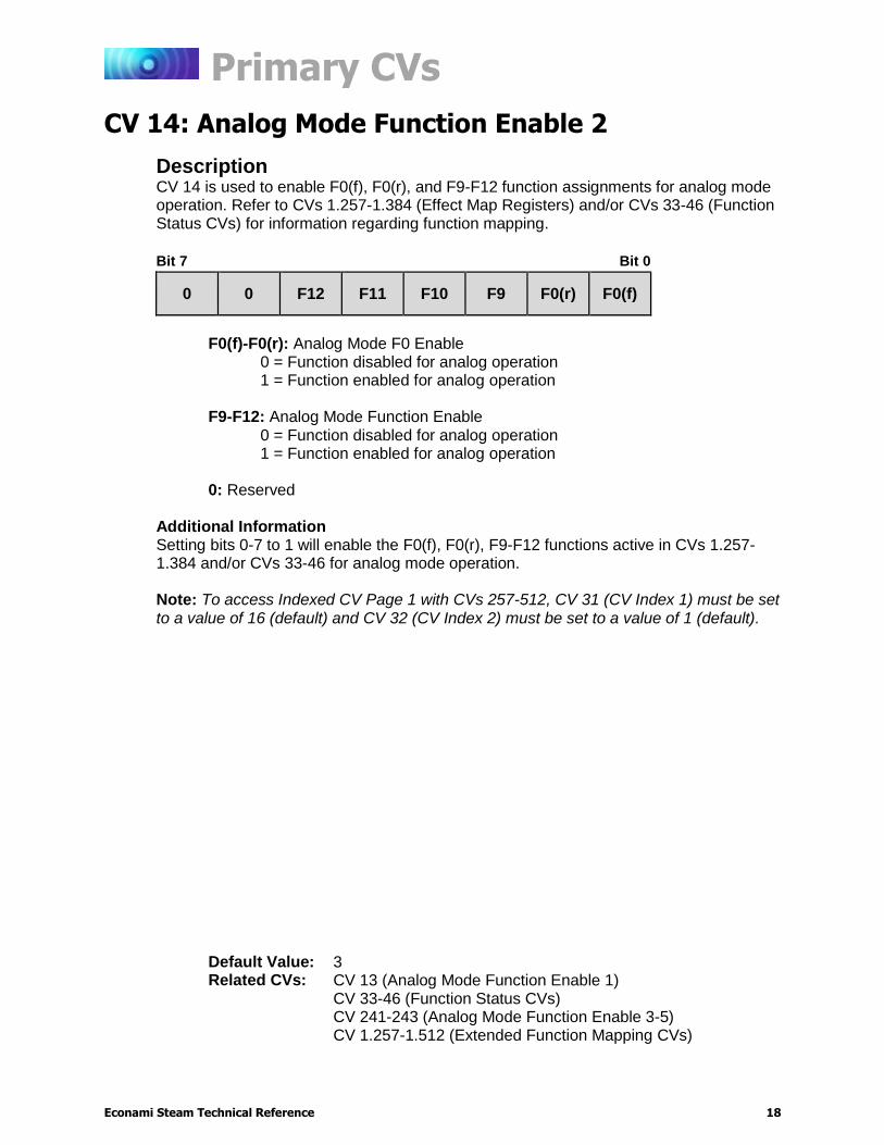
CV 14: Analog Mode Function Enable 2
Description CV 14 is used to enable F0(f), F0(r), and F9-F12 function assignments for analog mode operation. Refer to CVs 1.257-1.384 (Effect Map Registers) and/or CVs 33-46 (Function Status CVs) for information regarding function mapping.
Bit 7 Bit 0
0 0 F12 F11 F10 F9 F0(r) F0(f)
F0(f)-F0(r): Analog Mode F0 Enable
0 = Function disabled for analog operation 1 = Function enabled for analog operation
F9-F12: Analog Mode Function Enable
0 = Function disabled for analog operation 1 = Function enabled for analog operation
0: Reserved
Additional Information Setting bits 0-7 to 1 will enable the F0(f), F0(r), F9-F12 functions active in CVs 1.257-1.384 and/or CVs 33-46 for analog mode operation. Note: To access Indexed CV Page 1 with CVs 257-512, CV 31 (CV Index 1) must be set to a value of 16 (default) and CV 32 (CV Index 2) must be set to a value of 1 (default).
Default Value: 3 Related CVs: CV 13 (Analog Mode Function Enable 1)
CV 33-46 (Function Status CVs) CV 241-243 (Analog Mode Function Enable 3-5) CV 1.257-1.512 (Extended Function Mapping CVs)
Primary CVs
Econami Steam Technical Reference 19
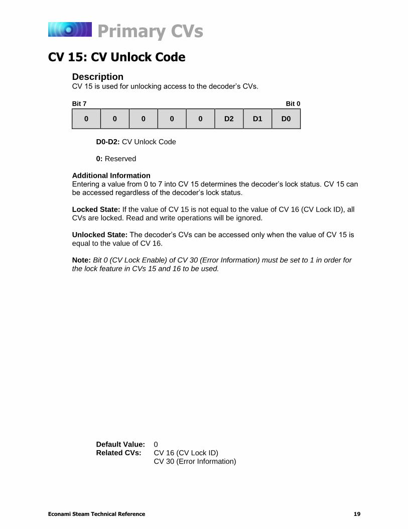
CV 15: CV Unlock Code
Description CV 15 is used for unlocking access to the decoder’s CVs.
Bit 7 Bit 0
0 0 0 0 0 D2 D1 D0
D0-D2: CV Unlock Code
0: Reserved
Additional Information Entering a value from 0 to 7 into CV 15 determines the decoder’s lock status. CV 15 can be accessed regardless of the decoder’s lock status. Locked State: If the value of CV 15 is not equal to the value of CV 16 (CV Lock ID), all CVs are locked. Read and write operations will be ignored. Unlocked State: The decoder’s CVs can be accessed only when the value of CV 15 is equal to the value of CV 16. Note: Bit 0 (CV Lock Enable) of CV 30 (Error Information) must be set to 1 in order for the lock feature in CVs 15 and 16 to be used.
Default Value: 0 Related CVs: CV 16 (CV Lock ID)
CV 30 (Error Information)
Primary CVs
Econami Steam Technical Reference 20
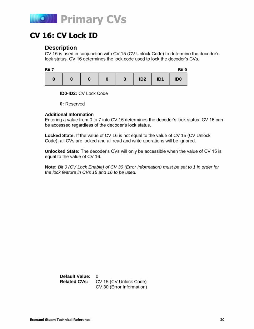
CV 16: CV Lock ID
Description CV 16 is used in conjunction with CV 15 (CV Unlock Code) to determine the decoder’s lock status. CV 16 determines the lock code used to lock the decoder’s CVs.
Bit 7 Bit 0
0 0 0 0 0 ID2 ID1 ID0
ID0-ID2: CV Lock Code 0: Reserved
Additional Information Entering a value from 0 to 7 into CV 16 determines the decoder’s lock status. CV 16 can be accessed regardless of the decoder’s lock status. Locked State: If the value of CV 16 is not equal to the value of CV 15 (CV Unlock Code), all CVs are locked and all read and write operations will be ignored. Unlocked State: The decoder’s CVs will only be accessible when the value of CV 15 is equal to the value of CV 16. Note: Bit 0 (CV Lock Enable) of CV 30 (Error Information) must be set to 1 in order for the lock feature in CVs 15 and 16 to be used.
Default Value: 0 Related CVs: CV 15 (CV Unlock Code)
CV 30 (Error Information)
Primary CVs
Econami Steam Technical Reference 21
CVs 17-18: Extended Address
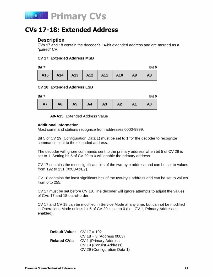
Description CVs 17 and 18 contain the decoder’s 14-bit extended address and are merged as a “paired” CV. CV 17: Extended Address MSB
Bit 7 Bit 0
A15 A14 A13 A12 A11 A10 A9 A8
CV 18: Extended Address LSB
Bit 7 Bit 0
A7 A6 A5 A4 A3 A2 A1 A0
A0-A15: Extended Address Value
Additional Information Most command stations recognize from addresses 0000-9999. Bit 5 of CV 29 (Configuration Data 1) must be set to 1 for the decoder to recognize commands sent to the extended address. The decoder will ignore commands sent to the primary address when bit 5 of CV 29 is set to 1. Setting bit 5 of CV 29 to 0 will enable the primary address. CV 17 contains the most significant bits of the two-byte address and can be set to values from 192 to 231 (0xC0-0xE7). CV 18 contains the least significant bits of the two-byte address and can be set to values from 0 to 255. CV 17 must be set before CV 18. The decoder will ignore attempts to adjust the values of CVs 17 and 18 out-of-order. CV 17 and CV 18 can be modified in Service Mode at any time, but cannot be modified in Operations Mode unless bit 5 of CV 29 is set to 0 (i.e., CV 1, Primary Address is enabled).
Default Value: CV 17 = 192 CV 18 = 3 (Address 0003) Related CVs: CV 1 (Primary Address
CV 19 (Consist Address) CV 29 (Configuration Data 1)
Primary CVs
Econami Steam Technical Reference 22
CV 19: Consist Address
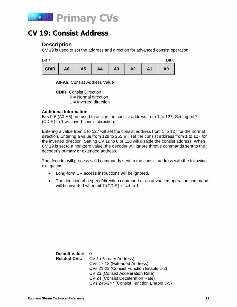
Description CV 19 is used to set the address and direction for advanced consist operation.
Bit 7 Bit 0
CDIR A6 A5 A4 A3 A2 A1 A0
A0-A6: Consist Address Value
CDIR: Consist Direction
0 = Normal direction 1 = Inverted direction
Additional Information Bits 0-6 (A0-A6) are used to assign the consist address from 1 to 127. Setting bit 7 (CDIR) to 1 will invert consist direction. Entering a value from 1 to 127 will set the consist address from 1 to 127 for the normal direction. Entering a value from 129 to 255 will set the consist address from 1 to 127 for the inverted direction. Setting CV 19 to 0 or 128 will disable the consist address. When CV 19 is set to a non-zero value, the decoder will ignore throttle commands sent to the decoder’s primary or extended address. The decoder will process valid commands sent to the consist address with the following exceptions:
Long-form CV access instructions will be ignored.
The direction of a speed/direction command or an advanced operation command will be inverted when bit 7 (CDIR) is set to 1.
Default Value: 0 Related CVs: CV 1 (Primary Address)
CVs 17-18 (Extended Address) CVs 21-22 (Consist Function Enable 1-2) CV 23 (Consist Acceleration Rate) CV 24 (Consist Deceleration Rate) CVs 245-247 (Consist Function Enable 3-5)
Primary CVs
Econami Steam Technical Reference 23
CV 21: Consist Function Enable 1
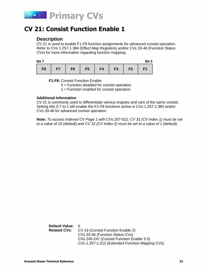
Description CV 21 is used to enable F1-F8 function assignments for advanced consist operation. Refer to CVs 1.257-1.384 (Effect Map Registers) and/or CVs 33-46 (Function Status CVs) for more information regarding function mapping.
Bit 7 Bit 0
F8 F7 F6 F5 F4 F3 F2 F1
F1-F8: Consist Function Enable
0 = Function disabled for consist operation 1 = Function enabled for consist operation
Additional Information CV 21 is commonly used to differentiate various engines and cars of the same consist. Setting bits 0-7 to 1 will enable the F1-F8 functions active in CVs 1.257-1.384 and/or CVs 33-46 for advanced consist operation.
Note: To access Indexed CV Page 1 with CVs 257-512, CV 31 (CV Index 1) must be set to a value of 16 (default) and CV 32 (CV Index 2) must be set to a value of 1 (default).
Default Value: 0 Related CVs: CV 19 (Consist Function Enable 2)
CVs 33-46 (Function Status CVs) CVs 245-247 (Consist Function Enable 3-5) CVs 1.257-1.512 (Extended Function Mapping CVs)
Primary CVs
Econami Steam Technical Reference 24
CV 22: Consist Function Enable 2
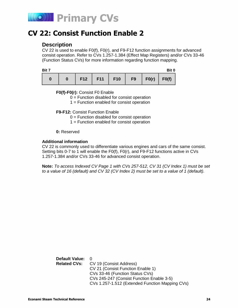
Description CV 22 is used to enable F0(f), F0(r), and F9-F12 function assignments for advanced consist operation. Refer to CVs 1.257-1.384 (Effect Map Registers) and/or CVs 33-46 (Function Status CVs) for more information regarding function mapping.
Bit 7 Bit 0
0 0 F12 F11 F10 F9 F0(r) F0(f)
F0(f)-F0(r): Consist F0 Enable
0 = Function disabled for consist operation 1 = Function enabled for consist operation
F9-F12: Consist Function Enable
0 = Function disabled for consist operation 1 = Function enabled for consist operation
0: Reserved
Additional information CV 22 is commonly used to differentiate various engines and cars of the same consist. Setting bits 0-7 to 1 will enable the F0(f), F0(r), and F9-F12 functions active in CVs 1.257-1.384 and/or CVs 33-46 for advanced consist operation.
Note: To access Indexed CV Page 1 with CVs 257-512, CV 31 (CV Index 1) must be set to a value of 16 (default) and CV 32 (CV Index 2) must be set to a value of 1 (default).
Default Value: 0 Related CVs: CV 19 (Consist Address)
CV 21 (Consist Function Enable 1) CVs 33-46 (Function Status CVs) CVs 245-247 (Consist Function Enable 3-5) CVs 1.257-1.512 (Extended Function Mapping CVs)

Primary CVs
Econami Steam Technical Reference 25
CV 23: Consist Acceleration Rate
Description CV 23 is used to set the consist acceleration rate. CV 19 must contain a valid consist address for the consist acceleration rate to be active.
Bit 7 Bit 0
SIGN D6 D5 D4 D3 D2 D1 D0
D0-D6: Consist Acceleration Offset SIGN: Sign
0 = Positive value 1 = Negative value
Additional Information The value of CV 23 determines the consist acceleration rate in relation to CV 3 (Baseline Acceleration Rate). When the consist address is active, the consist acceleration rate is added to or subtracted from the decoder’s baseline acceleration rate depending on the sign bit. Entering a value from 1 to 127 into CV 23 will increase the consist acceleration rate from the baseline acceleration rate in CV 3. Entering values from 129 to 255 into CV 23 will decrease the consist acceleration rate from the baseline acceleration rate in CV 3. Values of 0 and 128 will disable the consist acceleration rate and the decoder will use the value in CV 3.
When bit 7 (SIGN) of CV 23 is set to 0, the value added to CV 3 will be positive, where if bit 7 is set to 1, the value added to CV 3 will be negative:
0-127 128-255
0 = 0 128 = 0
1 = 1 129 = -1
.
.
.
.
.
.
127 = 127 255 = -127
Acceleration is calculated as:
Seconds/Speed Step = (CV 3 + CV 23) × 0.896 ÷ Number of Speed Steps
Default Value: 0 Related CVs: CV 3 (Baseline Acceleration Rate)
CV 4 (Baseline Deceleration Rate) CV 19 (Consist Address) CV 24 (Consist Deceleration Rate)
Primary CVs
Econami Steam Technical Reference 26
CV 24: Consist Deceleration Rate
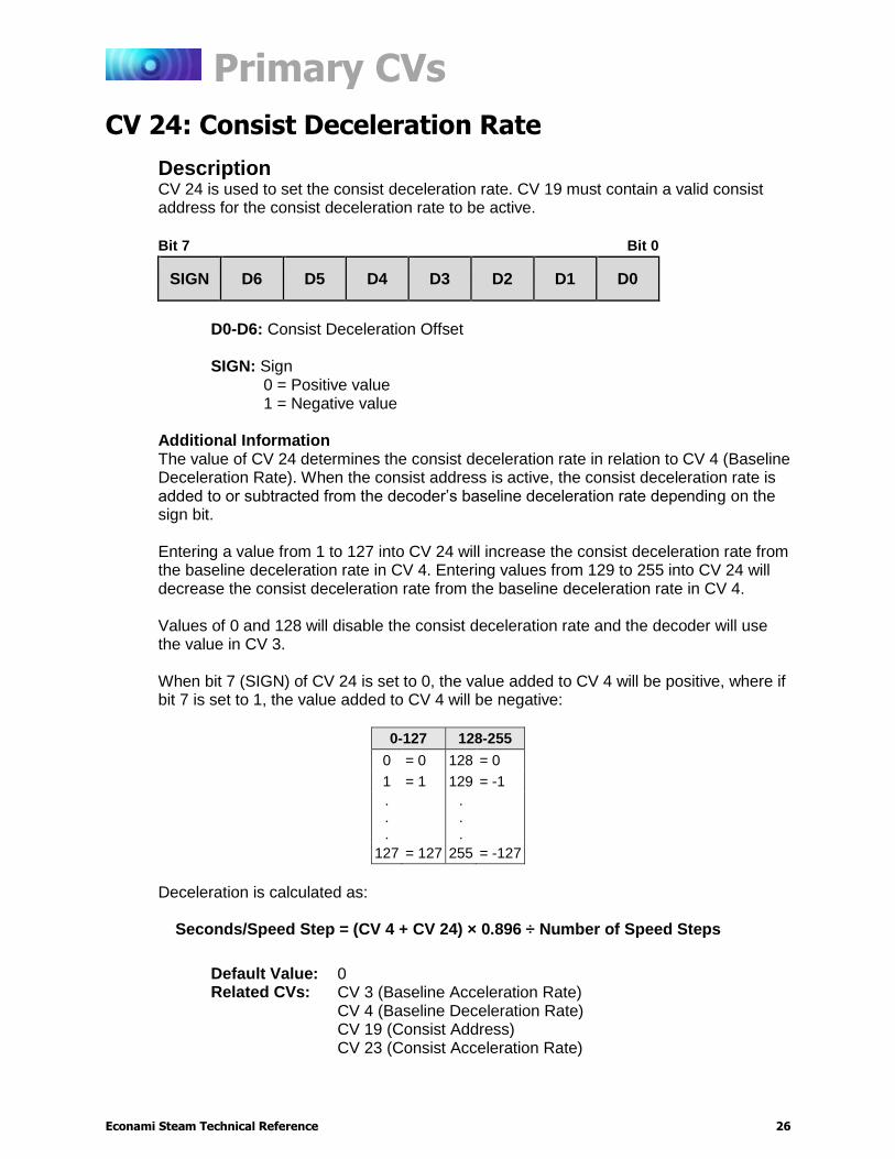
Description CV 24 is used to set the consist deceleration rate. CV 19 must contain a valid consist address for the consist deceleration rate to be active.
Bit 7 Bit 0
SIGN D6 D5 D4 D3 D2 D1 D0
D0-D6: Consist Deceleration Offset SIGN: Sign
0 = Positive value 1 = Negative value
Additional Information The value of CV 24 determines the consist deceleration rate in relation to CV 4 (Baseline Deceleration Rate). When the consist address is active, the consist deceleration rate is added to or subtracted from the decoder’s baseline deceleration rate depending on the sign bit. Entering a value from 1 to 127 into CV 24 will increase the consist deceleration rate from the baseline deceleration rate in CV 4. Entering values from 129 to 255 into CV 24 will decrease the consist deceleration rate from the baseline deceleration rate in CV 4. Values of 0 and 128 will disable the consist deceleration rate and the decoder will use the value in CV 3.
When bit 7 (SIGN) of CV 24 is set to 0, the value added to CV 4 will be positive, where if bit 7 is set to 1, the value added to CV 4 will be negative:
0-127 128-255
0 = 0 128 = 0
1 = 1 129 = -1
.
.
.
.
.
.
127 = 127 255 = -127
Deceleration is calculated as:
Seconds/Speed Step = (CV 4 + CV 24) × 0.896 ÷ Number of Speed Steps
Default Value: 0 Related CVs: CV 3 (Baseline Acceleration Rate)
CV 4 (Baseline Deceleration Rate) CV 19 (Consist Address) CV 23 (Consist Acceleration Rate)
Primary CVs
Econami Steam Technical Reference 27
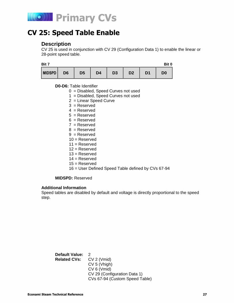
CV 25: Speed Table Enable
Description CV 25 is used in conjunction with CV 29 (Configuration Data 1) to enable the linear or 28-point speed table.
Bit 7 Bit 0
MIDSPD D6 D5 D4 D3 D2 D1 D0
D0-D6: Table Identifier
0 = Disabled, Speed Curves not used 1 = Disabled, Speed Curves not used 2 = Linear Speed Curve 3 = Reserved 4 = Reserved 5 = Reserved 6 = Reserved 7 = Reserved 8 = Reserved 9 = Reserved 10 = Reserved 11 = Reserved 12 = Reserved 13 = Reserved 14 = Reserved 15 = Reserved 16 = User Defined Speed Table defined by CVs 67-94
MIDSPD: Reserved
Additional Information Speed tables are disabled by default and voltage is directly proportional to the speed step.
Default Value: 2 Related CVs: CV 2 (Vmid)
CV 5 (Vhigh) CV 6 (Vmid) CV 29 (Configuration Data 1) CVs 67-94 (Custom Speed Table)
Primary CVs
Econami Steam Technical Reference 28
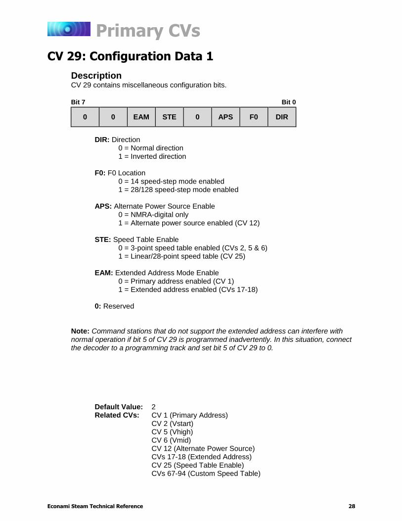
CV 29: Configuration Data 1
Description CV 29 contains miscellaneous configuration bits.
Bit 7 Bit 0
0 0 EAM STE 0 APS F0 DIR
DIR: Direction
0 = Normal direction 1 = Inverted direction
F0: F0 Location
0 = 14 speed-step mode enabled 1 = 28/128 speed-step mode enabled
APS: Alternate Power Source Enable
0 = NMRA-digital only 1 = Alternate power source enabled (CV 12)
STE: Speed Table Enable
0 = 3-point speed table enabled (CVs 2, 5 & 6) 1 = Linear/28-point speed table (CV 25)
EAM: Extended Address Mode Enable
0 = Primary address enabled (CV 1) 1 = Extended address enabled (CVs 17-18)
0: Reserved
Note: Command stations that do not support the extended address can interfere with normal operation if bit 5 of CV 29 is programmed inadvertently. In this situation, connect the decoder to a programming track and set bit 5 of CV 29 to 0.
Default Value: 2 Related CVs: CV 1 (Primary Address)
CV 2 (Vstart) CV 5 (Vhigh) CV 6 (Vmid) CV 12 (Alternate Power Source) CVs 17-18 (Extended Address) CV 25 (Speed Table Enable) CVs 67-94 (Custom Speed Table)

Primary CVs
Econami Steam Technical Reference 29
CV 30: Error Information
Description CV 30 is used to allow the decoder’s CVs to be locked and unlocked with CV 15 (CV Unlock Code) and CV 16 (CV Lock ID).
Bit 7 Bit 0
0 0 0 0 0 0 0 LCK
LCK: CV Lock/Unlock Enable
0 = CV lock/unlock feature disabled 1 = CV lock/unlock feature enabled (CVs 15-16)
0: Reserved
Default Value: 0 Related CVs: CV 15 (CV Unlock Code)
CV 16 (CV Lock ID)
Primary CVs
Econami Steam Technical Reference 30
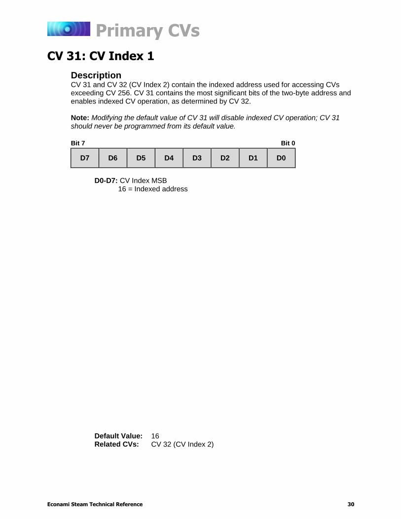
CV 31: CV Index 1
Description CV 31 and CV 32 (CV Index 2) contain the indexed address used for accessing CVs exceeding CV 256. CV 31 contains the most significant bits of the two-byte address and enables indexed CV operation, as determined by CV 32. Note: Modifying the default value of CV 31 will disable indexed CV operation; CV 31 should never be programmed from its default value.
Bit 7 Bit 0
D7 D6 D5 D4 D3 D2 D1 D0
D0-D7: CV Index MSB
16 = Indexed address
Default Value: 16 Related CVs: CV 32 (CV Index 2)
Primary CVs
Econami Steam Technical Reference 31
CV 32: CV Index 2
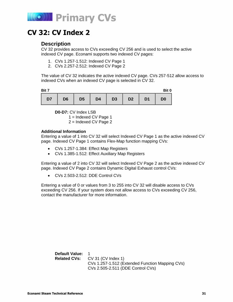
Description CV 32 provides access to CVs exceeding CV 256 and is used to select the active indexed CV page. Econami supports two indexed CV pages:
1. CVs 1.257-1.512: Indexed CV Page 1 2. CVs 2.257-2.512: Indexed CV Page 2
The value of CV 32 indicates the active indexed CV page. CVs 257-512 allow access to indexed CVs when an indexed CV page is selected in CV 32.
Bit 7 Bit 0
D7 D6 D5 D4 D3 D2 D1 D0
D0-D7: CV Index LSB
1 = Indexed CV Page 1 2 = Indexed CV Page 2
Additional Information Entering a value of 1 into CV 32 will select Indexed CV Page 1 as the active indexed CV page. Indexed CV Page 1 contains Flex-Map function mapping CVs:
CVs 1.257-1.384: Effect Map Registers
CVs 1.385-1.512: Effect Auxiliary Map Registers Entering a value of 2 into CV 32 will select Indexed CV Page 2 as the active indexed CV page. Indexed CV Page 2 contains Dynamic Digital Exhaust control CVs:
CVs 2.503-2.512: DDE Control CVs
Entering a value of 0 or values from 3 to 255 into CV 32 will disable access to CVs exceeding CV 256. If your system does not allow access to CVs exceeding CV 256, contact the manufacturer for more information.
Default Value: 1 Related CVs: CV 31 (CV Index 1)
CVs 1.257-1.512 (Extended Function Mapping CVs) CVs 2.505-2.511 (DDE Control CVs)

Primary CVs
Econami Steam Technical Reference 32
CVs 33-46: Function Status CVs
Function Status CVs 33-46 can be used to map a limited range of effects to functions F0-F12 and are included to remain consistent with NMRA Standards for DCC Configuration Variables (S-9.2.2, p.7). Note: CVs 33-46 are set to values of 0 by default, are a secondary method of function mapping, and are not used to determine Econami’s default function assignments. CVs 1.257-1.512 (Extended Function Mapping CVs) provide default function assignments for 28 function keys and offer comprehensive function mapping support for all of Econami’s effects in an uncomplicated and versatile format. However, mapping an effect to a function key (F0(f), F0(r), or F1-F12) using CVs 33-46 will override the corresponding function assignment mapped within CVs 1.257-1.384. Effects mapped to CV 33 (F0(f) Output Location) can be activated in the forward direction only and effects mapped to CV 34 (F0(r) Output Location) can be activated in the reverse direction only. This output is bidirectional only when same effect has been mapped to both CVs. The function mapping table provided below indicates the values used for mapping functions to effects. All provided effects cannot be mapped to all F0-F12 functions keys.
Function Output Map
Fu
ncti
on
Ke
y
CV
HL O
utp
ut
BL O
utp
ut
Wh
istle
Be
ll
FX
3 O
utp
ut
FX
4 O
utp
ut
Dynam
o
Short
Whis
tle
Cylin
der
Cocks
Wate
r S
top
Dim
mer
Mute
Reserv
ed
Bra
kes
Coup
ler
F0(f) 33 1 2 4 8 16 32 64 128
F0(r) 34 1 2 4 8 16 32 64 128
F1 35 1 2 4 8 16 32 64 128
F2 36 1 2 4 8 16 32 64 128
F3 37
1 2 4 8 16 32 64 128
F4 38 1 2 4 8 16 32 64 128
F5 39 1 2 4 8 16 32 64 128
F6 40 1 2 4 8 16 32 64 128
F7 41
1 2 4 8 16 32 64 128
F8 42 1 2 4 8 16 32 64 128
F9 43 1 2 4 8 16 32 64 128
F10 44
1 2 4 8 16 32 64 128
F11 45 1 2 4 8 16 32 64 128
F12 46 1 2 4 8 16 32 64 128

Primary CVs
Econami Steam Technical Reference 33
CV 33: F0(f) Output Location
Description
CV 33 is used to map a given effect to the F0(f) function key. The enabled effect will be activated when the F0(f) function is turned on. Disabled effects will have no relation to the F0(f) function key.
Bit 7 Bit 0
SWH DYN FX4 FX3 BEL WH BL HL
HL: Headlight Output
0 = Headlight disabled 1 = Headlight enabled
BL: Backup Light Output 0 = Backup light disabled 1 = Backup light enabled
WH: Whistle 0 = Whistle disabled 1 = Whistle enabled
BEL: Bell 0 = Bell disabled 1 = Bell enabled
FX3: FX3 Output 0 = FX3 disabled 1 = FX3 enabled
FX4: FX4 Output 0 = FX4 disabled 1 = FX4 enabled
DYN: Dynamo 0 = Dynamo disabled 1 = Dynamo enabled
SWH: Short Whistle 0 = Short whistle disabled 1 = Short whistle enabled
Default Value: 0
Primary CVs
Econami Steam Technical Reference 34
CV 34: F0(r) Output Location
Description
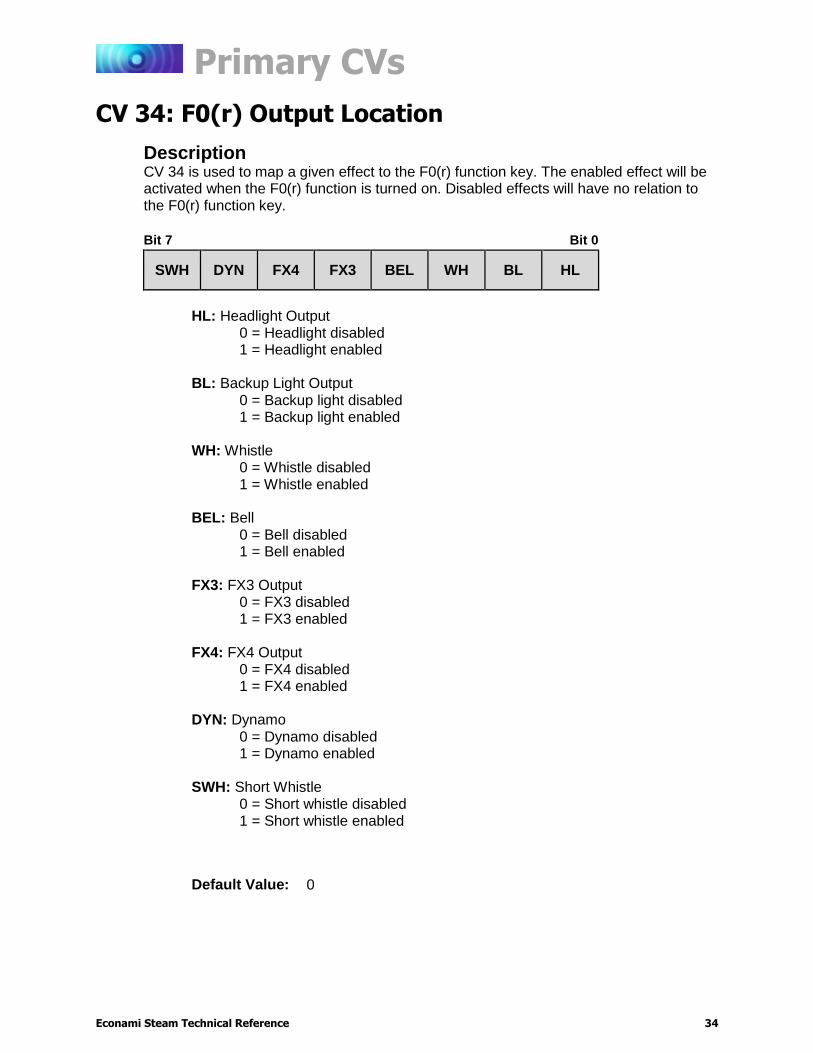
CV 34 is used to map a given effect to the F0(r) function key. The enabled effect will be activated when the F0(r) function is turned on. Disabled effects will have no relation to the F0(r) function key.
Bit 7 Bit 0
SWH DYN FX4 FX3 BEL WH BL HL
HL: Headlight Output
0 = Headlight disabled 1 = Headlight enabled
BL: Backup Light Output 0 = Backup light disabled 1 = Backup light enabled
WH: Whistle 0 = Whistle disabled 1 = Whistle enabled
BEL: Bell 0 = Bell disabled 1 = Bell enabled
FX3: FX3 Output 0 = FX3 disabled 1 = FX3 enabled
FX4: FX4 Output 0 = FX4 disabled 1 = FX4 enabled
DYN: Dynamo 0 = Dynamo disabled 1 = Dynamo enabled
SWH: Short Whistle 0 = Short whistle disabled 1 = Short whistle enabled
Default Value: 0
Primary CVs
Econami Steam Technical Reference 35
CV 35: F1 Output Location
Description
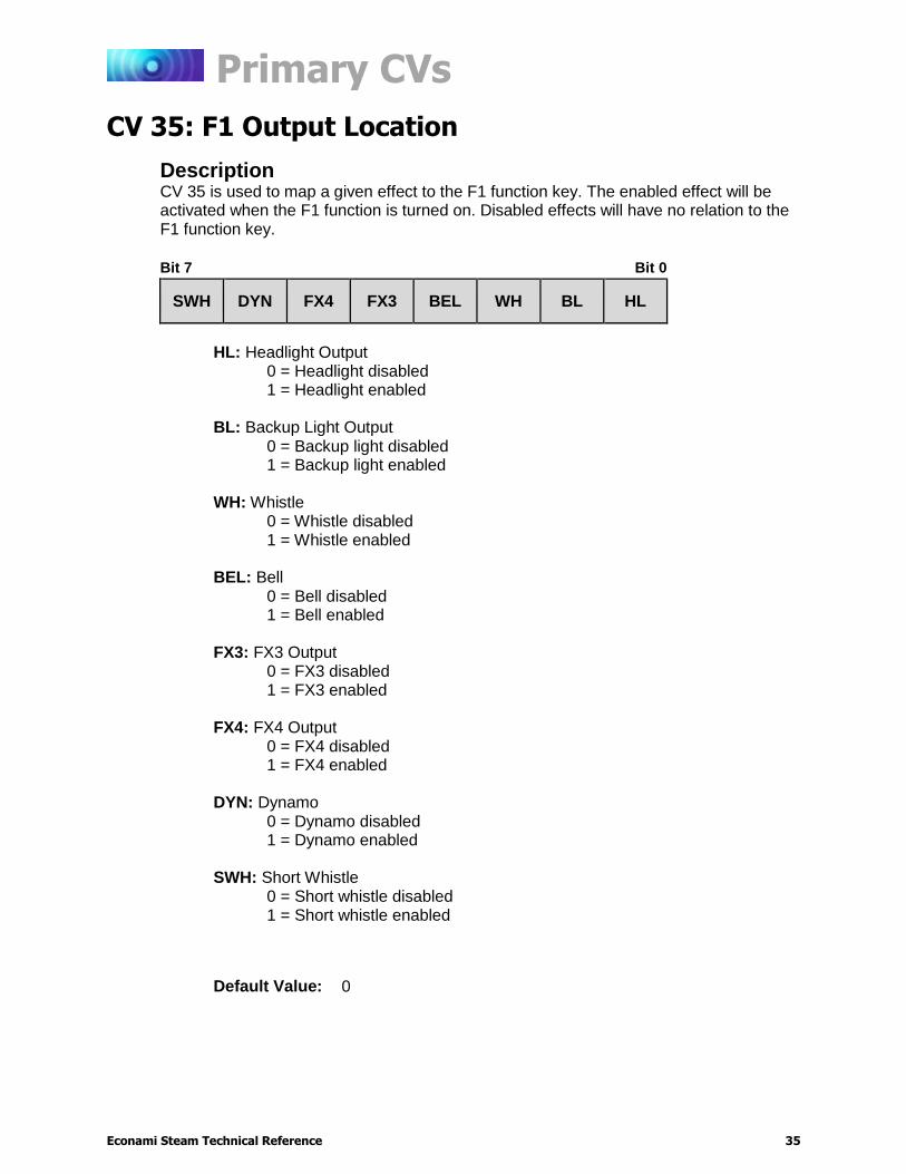
CV 35 is used to map a given effect to the F1 function key. The enabled effect will be activated when the F1 function is turned on. Disabled effects will have no relation to the F1 function key.
Bit 7 Bit 0
SWH DYN FX4 FX3 BEL WH BL HL
HL: Headlight Output
0 = Headlight disabled 1 = Headlight enabled
BL: Backup Light Output 0 = Backup light disabled 1 = Backup light enabled
WH: Whistle 0 = Whistle disabled 1 = Whistle enabled
BEL: Bell 0 = Bell disabled 1 = Bell enabled
FX3: FX3 Output 0 = FX3 disabled 1 = FX3 enabled
FX4: FX4 Output 0 = FX4 disabled 1 = FX4 enabled
DYN: Dynamo 0 = Dynamo disabled 1 = Dynamo enabled
SWH: Short Whistle 0 = Short whistle disabled 1 = Short whistle enabled
Default Value: 0

Primary CVs
Econami Steam Technical Reference 36
CV 36: F2 Output Location
Description
CV 36 is used to map a given effect to the F2 function key. The enabled effect will be activated when the F2 function is turned on. Disabled effects will have no relation to the F2 function key.
Bit 7 Bit 0
SWH DYN FX4 FX3 BEL WH BL HL
HL: Headlight Output
0 = Headlight disabled 1 = Headlight enabled
BL: Backup Light Output 0 = Backup light disabled 1 = Backup light enabled
WH: Whistle 0 = Whistle disabled 1 = Whistle enabled
BEL: Bell 0 = Bell disabled 1 = Bell enabled
FX3: FX3 Output 0 = FX3 disabled 1 = FX3 enabled
FX4: FX4 Output 0 = FX4 disabled 1 = FX4 enabled
DYN: Dynamo 0 = Dynamo disabled 1 = Dynamo enabled
SWH: Short Whistle 0 = Short whistle disabled 1 = Short whistle enabled
Default Value: 0

Primary CVs
Econami Steam Technical Reference 37
CV 37: F3 Output Location
Description
CV 37 is used to map a given effect to the F3 function key. The enabled effect will be activated when the F3 function is turned on. Disabled effects will have no relation to the F3 function key.
Bit 7 Bit 0
DIM WS CYL SWH DYN FX4 FX3 BEL
BEL: Bell
0 = Bell disabled 1 = Bell enabled
FX3: FX3 Output 0 = FX3 disabled 1 = FX3 enabled
FX4: FX4 Output 0 = FX4 disabled 1 = FX4 enabled
DYN: Dynamo 0 = Dynamo disabled 1 = Dynamo enabled
SWH: Short Whistle 0 = Short whistle disabled 1 = Short whistle enabled
CYL: Cylinder Cocks 0 = Cylinder cocks disabled 1 = Cylinder cocks enabled
WS: Water Stop 0 = Water stop disabled 1 = Water stop enabled
DIM: Dimmer 0 = Dimmer disabled 1 = Dimmer enabled
Default Value: 0

Primary CVs
Econami Steam Technical Reference 38
CV 38: F4 Output Location
Description
CV 38 is used to map a given effect to the F4 function key. The enabled effect will be activated when the F4 function is turned on. Disabled effects will have no relation to the F4 function key.
Bit 7 Bit 0
DIM WS CYL SWH DYN FX4 FX3 BEL
BEL: Bell
0 = Bell disabled 1 = Bell enabled
FX3: FX3 Output 0 = FX3 disabled 1 = FX3 enabled
FX4: FX4 Output 0 = FX4 disabled 1 = FX4 enabled
DYN: Dynamo 0 = Dynamo disabled 1 = Dynamo enabled
SWH: Short Whistle 0 = Short whistle disabled 1 = Short whistle enabled
CYL: Cylinder Cocks 0 = Cylinder cocks disabled 1 = Cylinder cocks enabled
WS: Water Stop 0 = Water stop disabled 1 = Water stop enabled
DIM: Dimmer 0 = Dimmer disabled 1 = Dimmer enabled
Default Value: 0

Primary CVs
Econami Steam Technical Reference 39
CV 39: F5 Output Location
Description
CV 39 is used to map a given effect to the F5 function key. The enabled effect will be activated when the F5 function is turned on. Disabled effects will have no relation to the F5 function key.
Bit 7 Bit 0
DIM WS CYL SWH DYN FX4 FX3 BEL
BEL: Bell
0 = Bell disabled 1 = Bell enabled
FX3: FX3 Output 0 = FX3 disabled 1 = FX3 enabled
FX4: FX4 Output 0 = FX4 disabled 1 = FX4 enabled
DYN: Dynamo 0 = Dynamo disabled 1 = Dynamo enabled
SWH: Short Whistle 0 = Short whistle disabled 1 = Short whistle enabled
CYL: Cylinder Cocks 0 = Cylinder cocks disabled 1 = Cylinder cocks enabled
WS: Water Stop 0 = Water stop disabled 1 = Water stop enabled
DIM: Dimmer 0 = Dimmer disabled 1 = Dimmer enabled
Default Value: 0
Primary CVs
Econami Steam Technical Reference 40
CV 40: F6 Output Location
Description
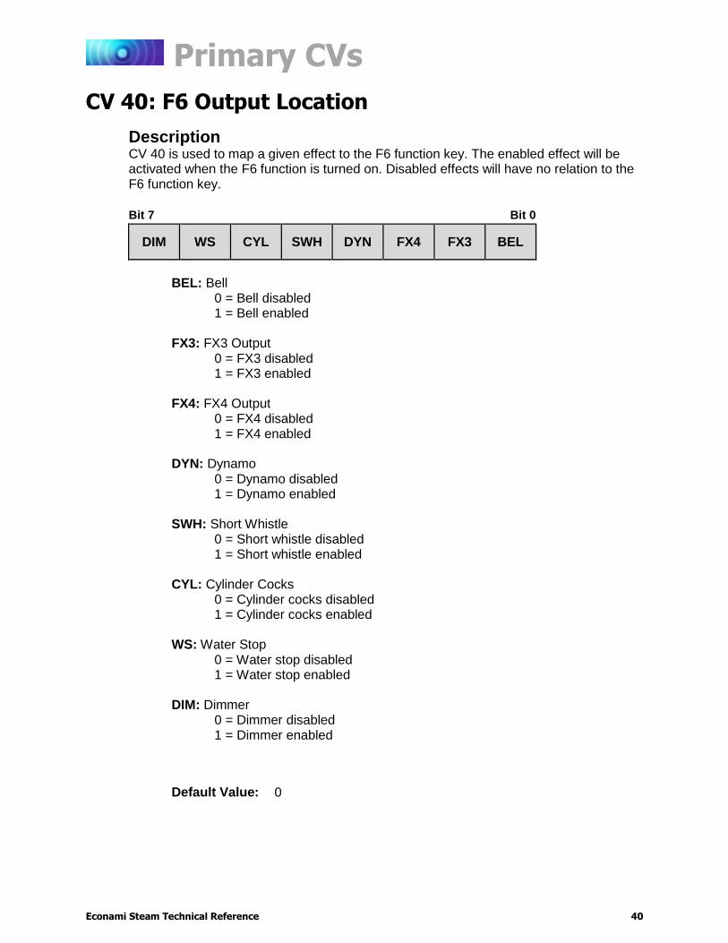
CV 40 is used to map a given effect to the F6 function key. The enabled effect will be activated when the F6 function is turned on. Disabled effects will have no relation to the F6 function key.
Bit 7 Bit 0
DIM WS CYL SWH DYN FX4 FX3 BEL
BEL: Bell
0 = Bell disabled 1 = Bell enabled
FX3: FX3 Output 0 = FX3 disabled 1 = FX3 enabled
FX4: FX4 Output 0 = FX4 disabled 1 = FX4 enabled
DYN: Dynamo 0 = Dynamo disabled 1 = Dynamo enabled
SWH: Short Whistle 0 = Short whistle disabled 1 = Short whistle enabled
CYL: Cylinder Cocks 0 = Cylinder cocks disabled 1 = Cylinder cocks enabled
WS: Water Stop 0 = Water stop disabled 1 = Water stop enabled
DIM: Dimmer 0 = Dimmer disabled 1 = Dimmer enabled
Default Value: 0
Primary CVs
Econami Steam Technical Reference 41
CV 41: F7 Output Location
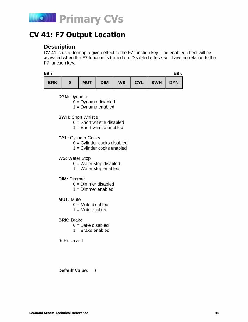
Description
CV 41 is used to map a given effect to the F7 function key. The enabled effect will be activated when the F7 function is turned on. Disabled effects will have no relation to the F7 function key.
Bit 7 Bit 0
BRK 0 MUT DIM WS CYL SWH DYN
DYN: Dynamo
0 = Dynamo disabled 1 = Dynamo enabled
SWH: Short Whistle 0 = Short whistle disabled 1 = Short whistle enabled
CYL: Cylinder Cocks 0 = Cylinder cocks disabled 1 = Cylinder cocks enabled
WS: Water Stop 0 = Water stop disabled 1 = Water stop enabled
DIM: Dimmer 0 = Dimmer disabled 1 = Dimmer enabled
MUT: Mute 0 = Mute disabled 1 = Mute enabled
BRK: Brake 0 = Bake disabled 1 = Brake enabled
0: Reserved
Default Value: 0

Primary CVs
Econami Steam Technical Reference 42
CV 42: F8 Output Location
Description
CV 42 is used to map a given effect to the F8 function key. The enabled effect will be activated when the F8 function is turned on. Disabled effects will have no relation to the F8 function key.
Bit 7 Bit 0
BRK 0 MUT DIM WS CYL SWH DYN
DYN: Dynamo
0 = Dynamo disabled 1 = Dynamo enabled
SWH: Short Whistle 0 = Short whistle disabled 1 = Short whistle enabled
CYL: Cylinder Cocks 0 = Cylinder cocks disabled 1 = Cylinder cocks enabled
WS: Water Stop 0 = Water stop disabled 1 = Water stop enabled
DIM: Dimmer 0 = Dimmer disabled 1 = Dimmer enabled
MUT: Mute 0 = Mute disabled 1 = Mute enabled
BRK: Brake 0 = Bake disabled 1 = Brake enabled
0: Reserved
Default Value: 0

Primary CVs
Econami Steam Technical Reference 43
CV 43: F9 Output Location
Description
CV 43 is used to map a given effect to the F9 function key. The enabled effect will be activated when the F9 function is turned on. Disabled effects will have no relation to the F9 function key.
Bit 7 Bit 0
BRK 0 MUT DIM WS CYL SWH DYN
DYN: Dynamo
0 = Dynamo disabled 1 = Dynamo enabled
SWH: Short Whistle 0 = Short whistle disabled 1 = Short whistle enabled
CYL: Cylinder Cocks 0 = Cylinder cocks disabled 1 = Cylinder cocks enabled
WS: Water Stop 0 = Water stop disabled 1 = Water stop enabled
DIM: Dimmer 0 = Dimmer disabled 1 = Dimmer enabled
MUT: Mute 0 = Mute disabled 1 = Mute enabled
BRK: Brake 0 = Bake disabled 1 = Brake enabled
0: Reserved
Default Value: 0

Primary CVs
Econami Steam Technical Reference 44
CV 44: F10 Output Location
Description
CV 44 is used to map a given effect to the F10 function key. The enabled effect will be activated when the F10 function is turned on. Disabled effects will have no relation to the F10 function key.
Bit 7 Bit 0
CPL BRK 0 MUT DIM WS CYL SWH
SWH: Short Whistle
0 = Short whistle disabled 1 = Short whistle enabled
CYL: Cylinder Cocks 0 = Cylinder cocks disabled 1 = Cylinder cocks enabled
WS: Water Stop 0 = Water stop disabled 1 = Water stop enabled
DIM: Dimmer 0 = Dimmer disabled 1 = Dimmer enabled
MUT: Mute 0 = Mute disabled 1 = Mute enabled
BRK: Brake 0 = Bake disabled 1 = Brake enabled
CPL: Coupler 0 = Coupler disabled 1 = Coupler enabled
0: Reserved
Default Value: 0

Primary CVs
Econami Steam Technical Reference 45
CV 45: F11 Output Location
Description
CV 45 is used to map a given effect to the F11 function key. The enabled effect will be activated when the F11 function is turned on. Disabled effects will have no relation to the F11 function key.
Bit 7 Bit 0
CPL BRK 0 MUT DIM WS CYL SWH
SWH: Short Whistle
0 = Short whistle disabled 1 = Short whistle enabled
CYL: Cylinder Cocks 0 = Cylinder cocks disabled 1 = Cylinder cocks enabled
WS: Water Stop 0 = Water stop disabled 1 = Water stop enabled
DIM: Dimmer 0 = Dimmer disabled 1 = Dimmer enabled
MUT: Mute 0 = Mute disabled 1 = Mute enabled
BRK: Brake 0 = Bake disabled 1 = Brake enabled
CPL: Coupler 0 = Coupler disabled 1 = Coupler enabled
0: Reserved
Default Value: 0

Primary CVs
Econami Steam Technical Reference 46
CV 46: F12 Output Location
Description
CV 46 is used to map a given effect to the F12 function key. The enabled effect will be activated when the F12 function is turned on. Disabled effects will have no relation to the F12 function key.
Bit 7 Bit 0
CPL BRK 0 MUT DIM WS CYL SWH
SWH: Short Whistle
0 = Short whistle disabled 1 = Short whistle enabled
CYL: Cylinder Cocks 0 = Cylinder cocks disabled 1 = Cylinder cocks enabled
WS: Water Stop 0 = Water stop disabled 1 = Water stop enabled
DIM: Dimmer 0 = Dimmer disabled 1 = Dimmer enabled
MUT: Mute 0 = Mute disabled 1 = Mute enabled
BRK: Brake 0 = Bake disabled 1 = Brake enabled
CPL: Coupler 0 = Coupler disabled 1 = Coupler enabled
0: Reserved
Default Value: 0
Lighting Effect CVs
Econami Steam Technical Reference 47
Lighting Effect CVs
CVs 49-54: Hyperlight Effect Select
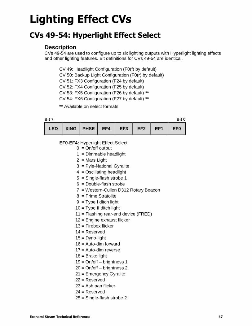
Description CVs 49-54 are used to configure up to six lighting outputs with Hyperlight lighting effects and other lighting features. Bit definitions for CVs 49-54 are identical.
CV 49: Headlight Configuration (F0(f) by default)
CV 50: Backup Light Configuration (F0(r) by default)
CV 51: FX3 Configuration (F24 by default)
CV 52: FX4 Configuration (F25 by default)
CV 53: FX5 Configuration (F26 by default) **
CV 54: FX6 Configuration (F27 by default) **
** Available on select formats
Bit 7 Bit 0
LED XING PHSE EF4 EF3 EF2 EF1 EF0
EF0-EF4: Hyperlight Effect Select
0
1
2
3
4
5
6
7
8
9
10
11
12
13
14
15
16
17
18
19
20
21
22
23
24
25
= On/off output
= Dimmable headlight
= Mars Light
= Pyle-National Gyralite
= Oscillating headlight
= Single-flash strobe 1
= Double-flash strobe
= Western-Cullen D312 Rotary Beacon
= Prime Stratolite
= Type I ditch light
= Type II ditch light
= Flashing rear-end device (FRED)
= Engine exhaust flicker
= Firebox flicker
= Reserved
= Dyno-light
= Auto-dim forward
= Auto-dim reverse
= Brake light
= On/off – brightness 1
= On/off – brightness 2
= Emergency Gyralite
= Reserved
= Ash pan flicker
= Reserved
= Single-flash strobe 2
Lighting Effect CVs
Econami Steam Technical Reference 48
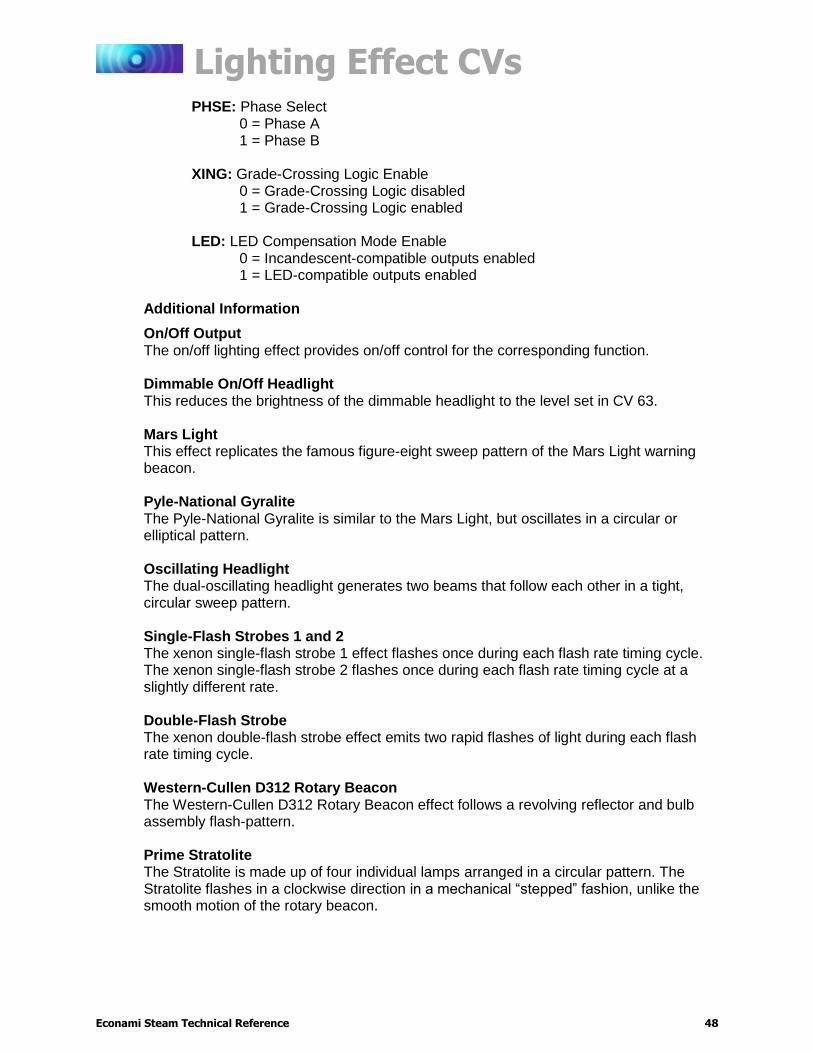
PHSE: Phase Select 0 = Phase A 1 = Phase B
XING: Grade-Crossing Logic Enable 0 = Grade-Crossing Logic disabled 1 = Grade-Crossing Logic enabled
LED: LED Compensation Mode Enable 0 = Incandescent-compatible outputs enabled 1 = LED-compatible outputs enabled
Additional Information
On/Off Output The on/off lighting effect provides on/off control for the corresponding function. Dimmable On/Off Headlight This reduces the brightness of the dimmable headlight to the level set in CV 63. Mars Light This effect replicates the famous figure-eight sweep pattern of the Mars Light warning beacon. Pyle-National Gyralite The Pyle-National Gyralite is similar to the Mars Light, but oscillates in a circular or elliptical pattern. Oscillating Headlight The dual-oscillating headlight generates two beams that follow each other in a tight, circular sweep pattern. Single-Flash Strobes 1 and 2 The xenon single-flash strobe 1 effect flashes once during each flash rate timing cycle. The xenon single-flash strobe 2 flashes once during each flash rate timing cycle at a slightly different rate. Double-Flash Strobe The xenon double-flash strobe effect emits two rapid flashes of light during each flash rate timing cycle. Western-Cullen D312 Rotary Beacon The Western-Cullen D312 Rotary Beacon effect follows a revolving reflector and bulb assembly flash-pattern. Prime Stratolite The Stratolite is made up of four individual lamps arranged in a circular pattern. The Stratolite flashes in a clockwise direction in a mechanical “stepped” fashion, unlike the smooth motion of the rotary beacon.
Lighting Effect CVs
Econami Steam Technical Reference 49
Ditch Lights I and II Ditch lights I and II flash together by default. When Grade-Crossing Logic is enabled, ditch light I assumes a steady “on” state before and after the crossing hold timer countdown. Conversely, ditch light II will remain off before and after the crossing hold timer countdown. To configure alternating ditch lights, set one lighting output to ditch light I or II and enable Grade-Crossing Logic, and then set a second lighting output to the same ditch light and enable Grade-Crossing Logic and phase offset. FRED (Flashing Rear End Device) The FRED effect is a flashing red taillight that indicates the rear of the train. Exhaust Flicker The exhaust flicker effect simulates a light flickering inside the cab. The flicker becomes more rapid and brighter as the locomotive emits higher volumes of exhaust to produce more power. The brightness of the flicker ranges from 0% to 100% in proportion to locomotive speed. Firebox Flicker The firebox flicker effect flickers at random to simulate the fire burning fuel in the firebox. Dyno-Light The Dyno-light effect synchronizes the lamp brightness with the output of the dynamo to simulate the spool-up and shut off of the dynamo, and the heating and cooling of the bulb filament. The brightness increases as the dynamo heats up and decreases as it cools down. Auto-Dim Forward and Reverse The auto-dim forward effect will automatically dim lighting outputs to the dimmer level in CV 63 when stopped or in the forward direction, and the auto-dim reverse effect will automatically dim lighting outputs to the dimmer level in CV 63 when stopped or in the reverse direction. Brake Light The brake light effect is dimmed to the brightness setting in CV 63 when active. The brake light brightness level will be automatically set to 100% when you turn on the brake function (F11 by default). On/Off Brightness 1 and 2 The on/off brightness 1 and 2 effects will set lighting outputs to the brightness levels of CVs 61 and 62, respectively. Emergency Gyralite The emergency Gyralite follows the same oscillating sweep pattern as the Gyralite, and will automatically disable all active lighting effects.
Lighting Effect CVs
Econami Steam Technical Reference 50
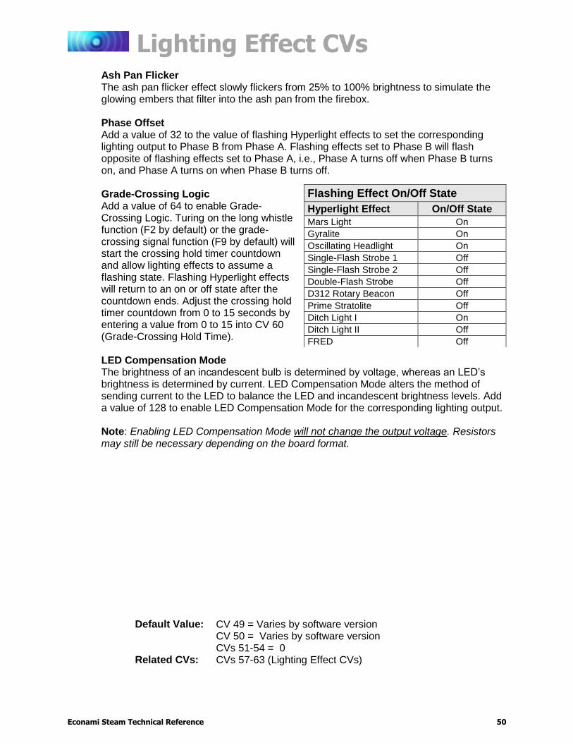
Ash Pan Flicker The ash pan flicker effect slowly flickers from 25% to 100% brightness to simulate the glowing embers that filter into the ash pan from the firebox.
Phase Offset Add a value of 32 to the value of flashing Hyperlight effects to set the corresponding lighting output to Phase B from Phase A. Flashing effects set to Phase B will flash opposite of flashing effects set to Phase A, i.e., Phase A turns off when Phase B turns on, and Phase A turns on when Phase B turns off. Grade-Crossing Logic Add a value of 64 to enable Grade-Crossing Logic. Turing on the long whistle function (F2 by default) or the grade-crossing signal function (F9 by default) will start the crossing hold timer countdown and allow lighting effects to assume a flashing state. Flashing Hyperlight effects will return to an on or off state after the countdown ends. Adjust the crossing hold timer countdown from 0 to 15 seconds by entering a value from 0 to 15 into CV 60 (Grade-Crossing Hold Time). LED Compensation Mode The brightness of an incandescent bulb is determined by voltage, whereas an LED’s brightness is determined by current. LED Compensation Mode alters the method of sending current to the LED to balance the LED and incandescent brightness levels. Add a value of 128 to enable LED Compensation Mode for the corresponding lighting output. Note: Enabling LED Compensation Mode will not change the output voltage. Resistors may still be necessary depending on the board format.
Flashing Effect On/Off State
Hyperlight Effect On/Off State
Mars Light On
Gyralite On
Oscillating Headlight On
Single-Flash Strobe 1 Off
Single-Flash Strobe 2 Off
Double-Flash Strobe Off
D312 Rotary Beacon Off
Prime Stratolite Off
Ditch Light I On
Ditch Light II Off
FRED Off
Default Value: CV 49 = Varies by software version CV 50 = Varies by software version CVs 51-54 = 0
Related CVs: CVs 57-63 (Lighting Effect CVs)
Lighting Effect CVs
Econami Steam Technical Reference 51
CV 57: Forward Direction Enable
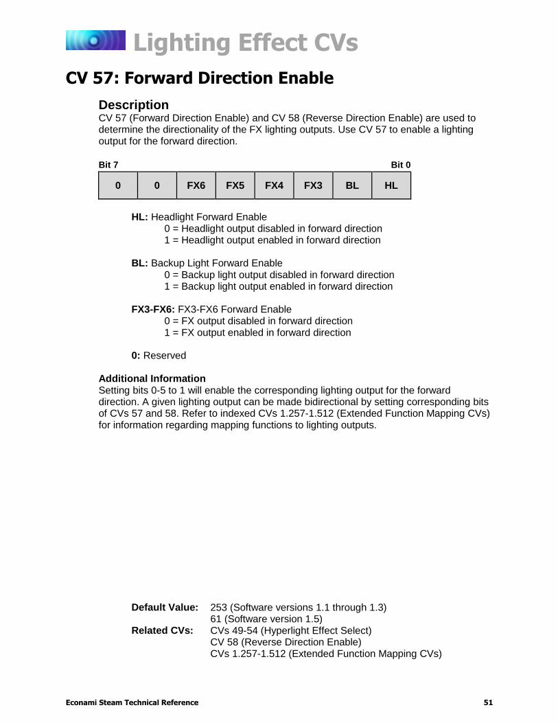
Description CV 57 (Forward Direction Enable) and CV 58 (Reverse Direction Enable) are used to determine the directionality of the FX lighting outputs. Use CV 57 to enable a lighting output for the forward direction.
Bit 7 Bit 0
0 0 FX6 FX5 FX4 FX3 BL HL
HL: Headlight Forward Enable
0 = Headlight output disabled in forward direction 1 = Headlight output enabled in forward direction
BL: Backup Light Forward Enable 0 = Backup light output disabled in forward direction 1 = Backup light output enabled in forward direction
FX3-FX6: FX3-FX6 Forward Enable 0 = FX output disabled in forward direction 1 = FX output enabled in forward direction
0: Reserved
Additional Information Setting bits 0-5 to 1 will enable the corresponding lighting output for the forward direction. A given lighting output can be made bidirectional by setting corresponding bits of CVs 57 and 58. Refer to indexed CVs 1.257-1.512 (Extended Function Mapping CVs) for information regarding mapping functions to lighting outputs.
Default Value: 253 (Software versions 1.1 through 1.3) 61 (Software version 1.5)
Related CVs: CVs 49-54 (Hyperlight Effect Select) CV 58 (Reverse Direction Enable) CVs 1.257-1.512 (Extended Function Mapping CVs)
Lighting Effect CVs
Econami Steam Technical Reference 52
CV 58: Reverse Direction Enable
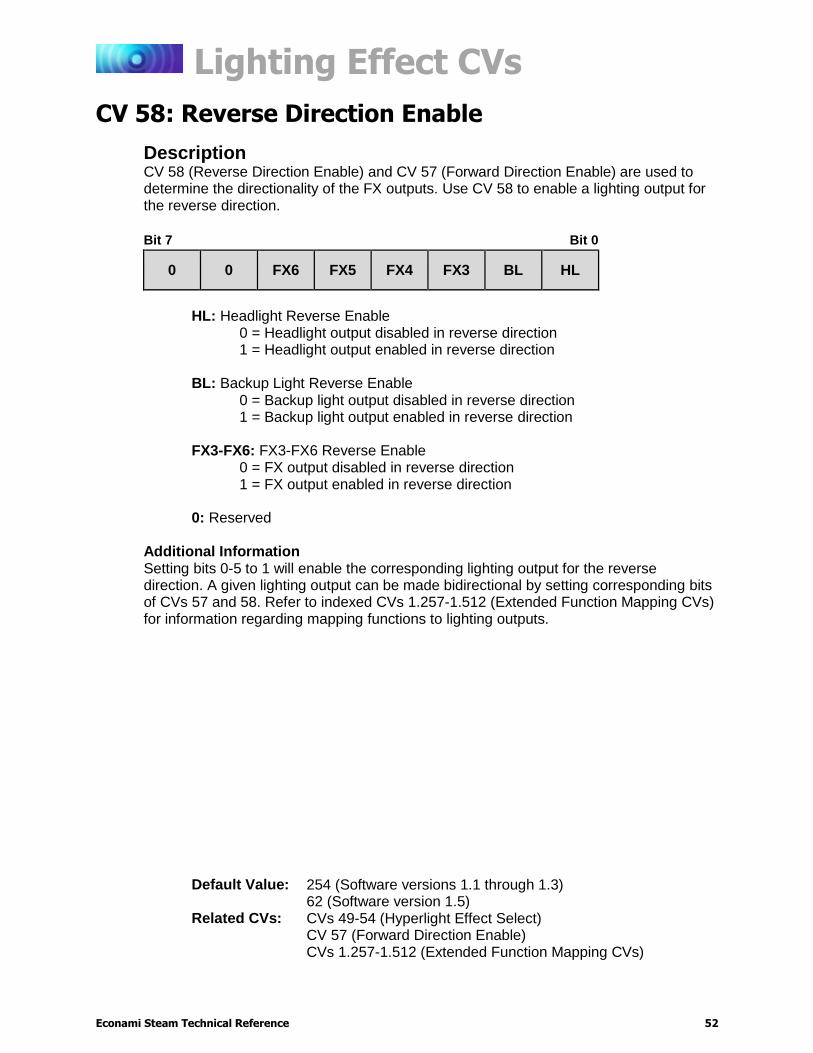
Description CV 58 (Reverse Direction Enable) and CV 57 (Forward Direction Enable) are used to determine the directionality of the FX outputs. Use CV 58 to enable a lighting output for the reverse direction.
Bit 7 Bit 0
0 0 FX6 FX5 FX4 FX3 BL HL
HL: Headlight Reverse Enable
0 = Headlight output disabled in reverse direction 1 = Headlight output enabled in reverse direction
BL: Backup Light Reverse Enable 0 = Backup light output disabled in reverse direction 1 = Backup light output enabled in reverse direction
FX3-FX6: FX3-FX6 Reverse Enable 0 = FX output disabled in reverse direction 1 = FX output enabled in reverse direction
0: Reserved
Additional Information Setting bits 0-5 to 1 will enable the corresponding lighting output for the reverse direction. A given lighting output can be made bidirectional by setting corresponding bits of CVs 57 and 58. Refer to indexed CVs 1.257-1.512 (Extended Function Mapping CVs) for information regarding mapping functions to lighting outputs.
Default Value: 254 (Software versions 1.1 through 1.3) 62 (Software version 1.5)
Related CVs: CVs 49-54 (Hyperlight Effect Select) CV 57 (Forward Direction Enable) CVs 1.257-1.512 (Extended Function Mapping CVs)

Lighting Effect CVs
Econami Steam Technical Reference 53
CV 59: Hyperlight Flash Rate
Description CV 59 is used to set the flash rate of all enabled flashing Hyperlight effects.
Bit 7 Bit 0
0 0 0 0 FR3 FR2 FR1 FR0
FR0-FR3: Hyperlight Flash Rate Select
0 = Fastest flash rate . . .
15 = Slowest flash rate
0: Reserved
Default Value: 2 (Software versions 1.1 through 1.3) 3 (Software version 1.5)
Related CVs: CVs 49-54 (Hyperlight Effect Select) CV 60 (Grade-Crossing Hold Time)
Lighting Effect CVs
Econami Steam Technical Reference 54
CV 60: Grade-Crossing Hold Time
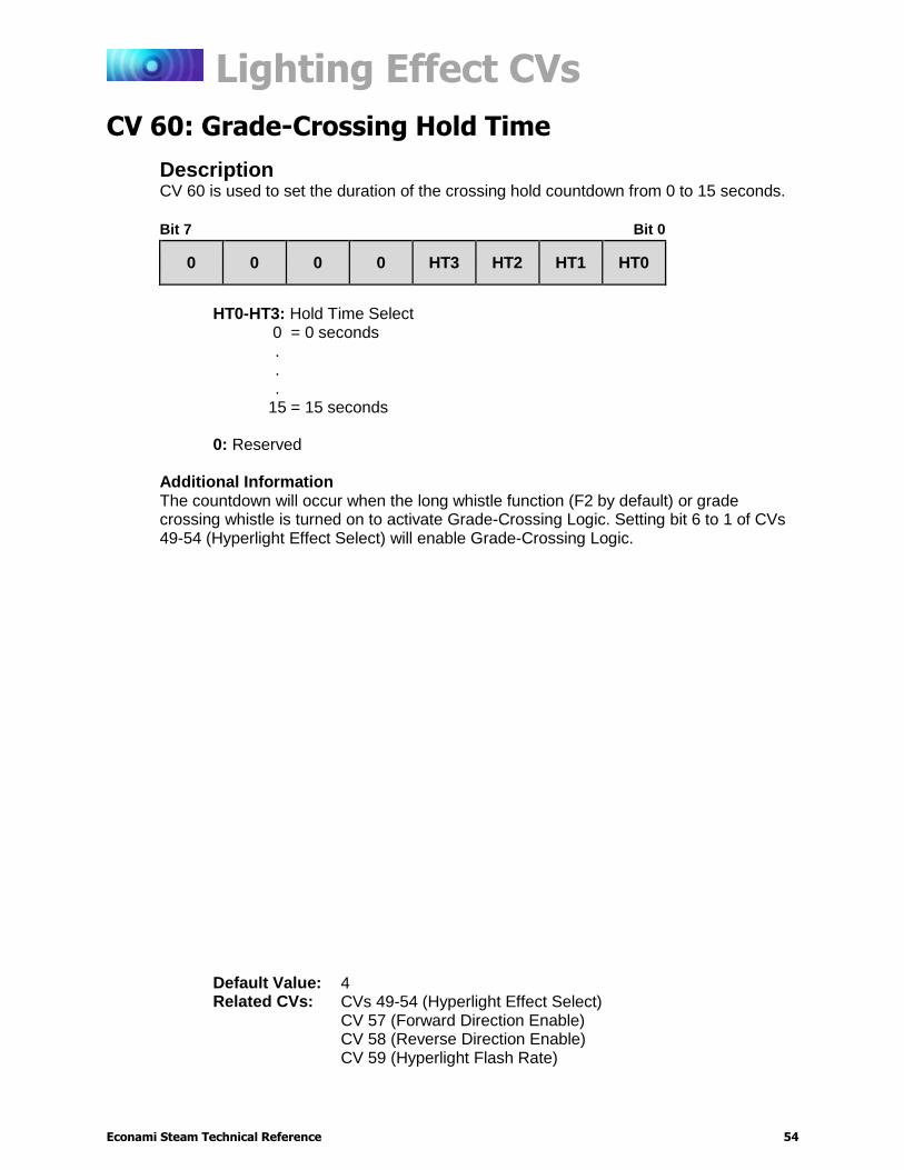
Description CV 60 is used to set the duration of the crossing hold countdown from 0 to 15 seconds.
Bit 7 Bit 0
0 0 0 0 HT3 HT2 HT1 HT0
HT0-HT3: Hold Time Select
0 = 0 seconds . . .
15 = 15 seconds
0: Reserved
Additional Information The countdown will occur when the long whistle function (F2 by default) or grade crossing whistle is turned on to activate Grade-Crossing Logic. Setting bit 6 to 1 of CVs 49-54 (Hyperlight Effect Select) will enable Grade-Crossing Logic.
Default Value: 4 Related CVs: CVs 49-54 (Hyperlight Effect Select)
CV 57 (Forward Direction Enable) CV 58 (Reverse Direction Enable) CV 59 (Hyperlight Flash Rate)
Lighting Effect CVs
Econami Steam Technical Reference 55
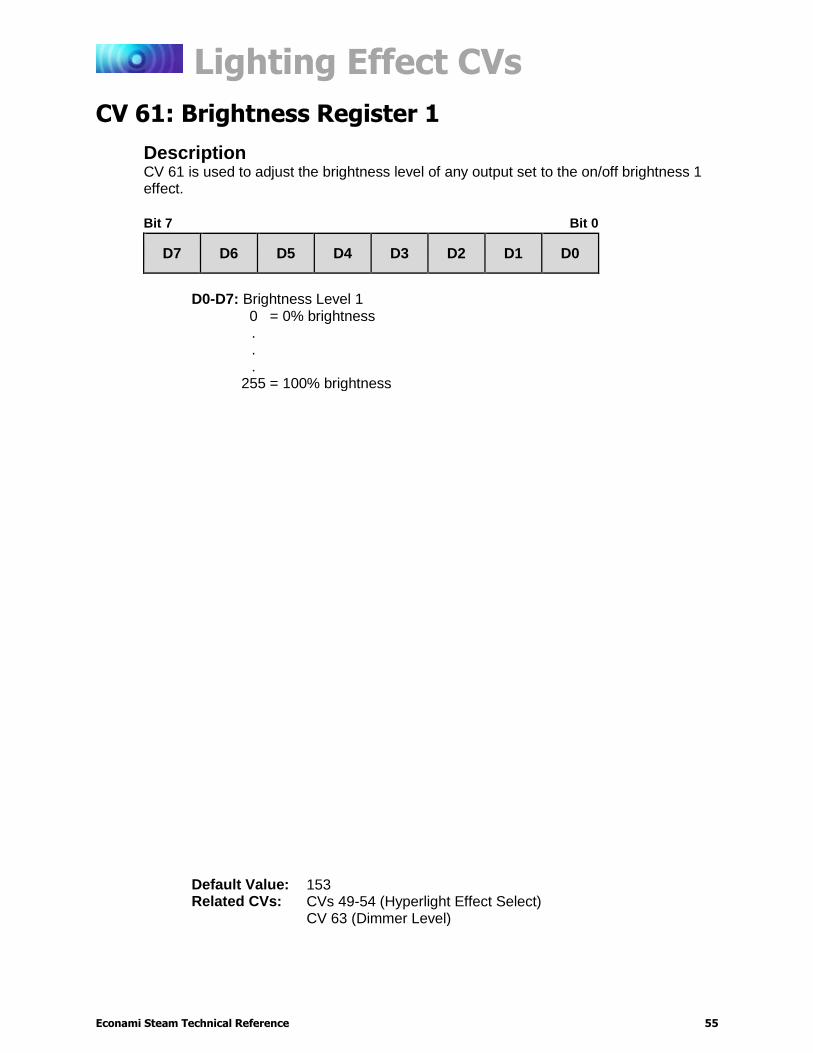
CV 61: Brightness Register 1
Description CV 61 is used to adjust the brightness level of any output set to the on/off brightness 1 effect.
Bit 7 Bit 0
D7 D6 D5 D4 D3 D2 D1 D0
D0-D7: Brightness Level 1
0 = 0% brightness . . .
255 = 100% brightness
Default Value: 153 Related CVs: CVs 49-54 (Hyperlight Effect Select)
CV 63 (Dimmer Level)
Lighting Effect CVs
Econami Steam Technical Reference 56
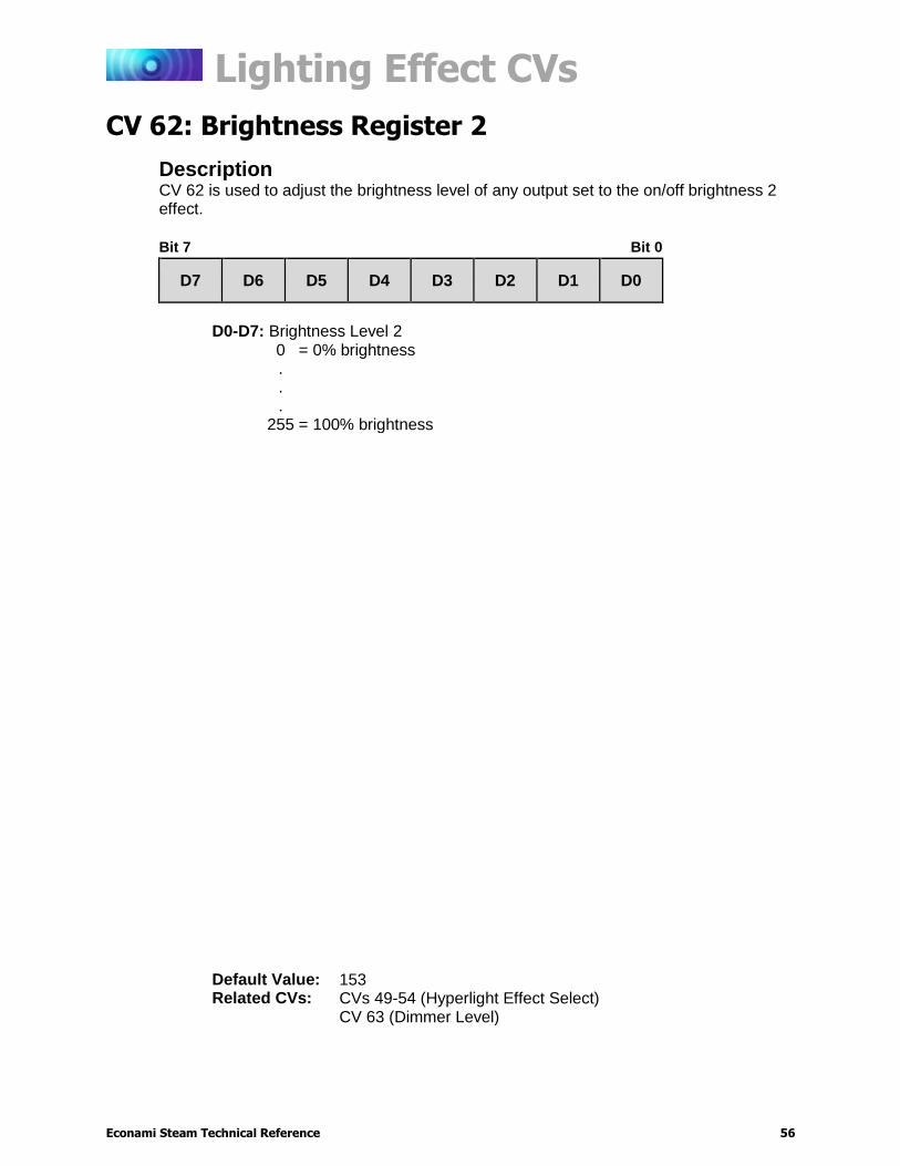
CV 62: Brightness Register 2
Description CV 62 is used to adjust the brightness level of any output set to the on/off brightness 2 effect.
Bit 7 Bit 0
D7 D6 D5 D4 D3 D2 D1 D0
D0-D7: Brightness Level 2
0 = 0% brightness . . .
255 = 100% brightness
Default Value: 153 Related CVs: CVs 49-54 (Hyperlight Effect Select)
CV 63 (Dimmer Level)

Lighting Effect CVs
Econami Steam Technical Reference 57
CV 63: Dimmer Level
Description CV 63 is used to adjust the brightness level of the on/off dimmable headlight effect. The brightness of the headlight will be automatically dimmed to the value of CV 63 when the dimmer function (F7 by default) is turned on.
Bit 7 Bit 0
D7 D6 D5 D4 D3 D2 D1 D0
D0-D7: Dimmer Level
0 = 0% brightness . . .
255 = 100% brightness
Default Value: 153 Related CVs: CVs 49-54 (Hyperlight Effect Select)
CV 61 (Brightness Register 1) CV 62 (Brightness Register 2)
Speed Table CVs
Econami Steam Technical Reference 58
Speed Table CVs
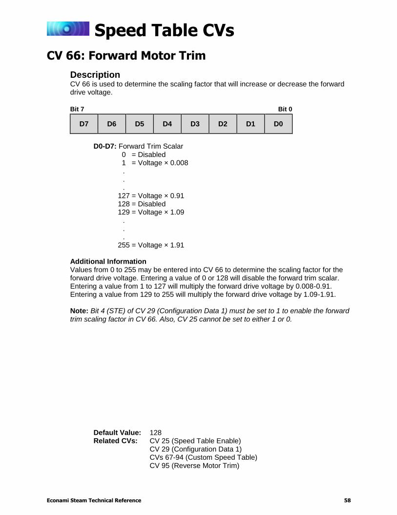
CV 66: Forward Motor Trim
Description CV 66 is used to determine the scaling factor that will increase or decrease the forward drive voltage.
Bit 7 Bit 0
D7 D6 D5 D4 D3 D2 D1 D0
D0-D7: Forward Trim Scalar
0 = Disabled 1 = Voltage × 0.008 . . .
127 = Voltage × 0.91 128 = Disabled 129 = Voltage × 1.09
.
.
.
255 = Voltage × 1.91
Additional Information Values from 0 to 255 may be entered into CV 66 to determine the scaling factor for the forward drive voltage. Entering a value of 0 or 128 will disable the forward trim scalar. Entering a value from 1 to 127 will multiply the forward drive voltage by 0.008-0.91. Entering a value from 129 to 255 will multiply the forward drive voltage by 1.09-1.91. Note: Bit 4 (STE) of CV 29 (Configuration Data 1) must be set to 1 to enable the forward trim scaling factor in CV 66. Also, CV 25 cannot be set to either 1 or 0.
Default Value: 128 Related CVs: CV 25 (Speed Table Enable)
CV 29 (Configuration Data 1) CVs 67-94 (Custom Speed Table) CV 95 (Reverse Motor Trim)
Speed Table CVs
Econami Steam Technical Reference 59
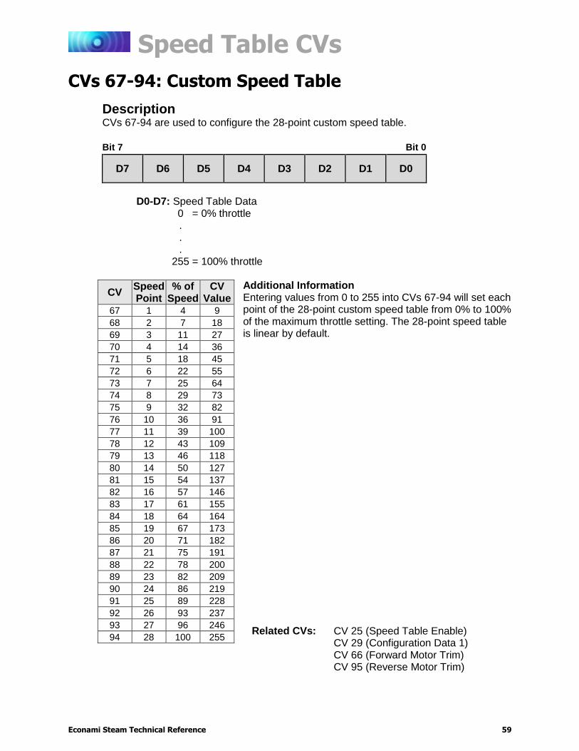
CVs 67-94: Custom Speed Table
Description CVs 67-94 are used to configure the 28-point custom speed table.
Bit 7 Bit 0
D7 D6 D5 D4 D3 D2 D1 D0
D0-D7: Speed Table Data
0 = 0% throttle . . .
255 = 100% throttle
Additional Information Entering values from 0 to 255 into CVs 67-94 will set each point of the 28-point custom speed table from 0% to 100% of the maximum throttle setting. The 28-point speed table is linear by default.
CV Speed Point
% of Speed
CV Value
67 1 4 9
68 2 7 18
69 3 11 27
70 4 14 36
71 5 18 45
72 6 22 55
73 7 25 64
74 8 29 73
75 9 32 82
76 10 36 91
77 11 39 100
78 12 43 109
79 13 46 118
80 14 50 127
81 15 54 137
82 16 57 146
83 17 61 155
84 18 64 164
85 19 67 173
86 20 71 182
87 21 75 191
88 22 78 200
89 23 82 209
90 24 86 219
91 25 89 228
92 26 93 237
93 27 96 246
94 28 100 255 Related CVs: CV 25 (Speed Table Enable)
CV 29 (Configuration Data 1) CV 66 (Forward Motor Trim) CV 95 (Reverse Motor Trim)

Speed Table CVs
Econami Steam Technical Reference 60
CV 95: Reverse Motor Trim
Description CV 95 is used to determine the scaling factor that will increase or decrease the reverse drive voltage.
Bit 7 Bit 0
D7 D6 D5 D4 D3 D2 D1 D0
D0-D7: Reverse Trim Scalar
0 = Disabled 1 = Voltage ÷ 0.008 . . .
127 = Voltage ÷ 0.91 128 = Disabled 129 = Voltage × 1.09
.
.
.
255 = Voltage × 1.91
Additional Information Values from 0 to 255 may be entered into CV 95 to determine the scaling factor for the reverse drive voltage. Entering a value of 0 or 128 will disable the reverse trim scalar. Entering a value from 1 to 127 will decrease the reverse drive voltage by 0.008-0.91. Entering a value from 129 to 255 will increase the reverse drive voltage by 1.09-1.91. Note: Bit 4 (STE) of CV 29 (Configuration Data 1) must be set to 1 to enable the reverse trim scaling factor in CV 95. Also, CV 25 cannot be set to either 1 or 0.
Default Value: 128 Related CVs: CV 25 (Speed Table Enable)
CV 29 (Configuration Data 1) CVs 67-94 (Custom Speed Table) CV 66 (Forward Motor Trim)
User Information CVs
Econami Steam Technical Reference 61
User Information CVs
CV 105: User Identifier 1
Description
CV 105 indicates the software’s major revision code and provides storage for user-supplied data. This CV has no other effect on decoder operation.
Bit 7 Bit 0
D7 D6 D5 D4 D3 D2 D1 D0
D0-D7: User Identifier Data
Additional Information This CV may be programmed with any value from 0 to 255. CV 105 will return to the software’s major revision code when the decoder is reset to factory settings.
Default Value: Varies by software revision Related CVs: CV 106 (User Identifier 2)
User Information CVs
Econami Steam Technical Reference 62
CV 106: User Identifier 2
Description
CV 106 indicates the software’s minor revision code. This CV may be used to provide storage for user-supplied data. This CV has no other effect on decoder operation.
Bit 7 Bit 0
D7 D6 D5 D4 D3 D2 D1 D0
D0-D7: User Identifier Data
Additional Information This CV may be programmed with any value from 0 to 255. CV 106 will return to the software’s minor revision code when the decoder is reset to factory settings.
Default Value: Varies by software revision Related CVs: CV 105 (User Identifier 1)
Sound Control CVs
Econami Steam Technical Reference 63
Sound Control CVs
CV 112: Sound Configuration 1
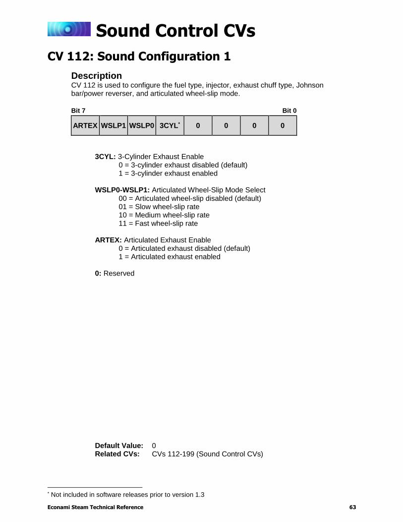
Description CV 112 is used to configure the fuel type, injector, exhaust chuff type, Johnson bar/power reverser, and articulated wheel-slip mode.
Bit 7 Bit 0
ARTEX WSLP1 WSLP0 3CYL* 0 0 0 0
3CYL: 3-Cylinder Exhaust Enable 0 = 3-cylinder exhaust disabled (default) 1 = 3-cylinder exhaust enabled
WSLP0-WSLP1: Articulated Wheel-Slip Mode Select
00 = Articulated wheel-slip disabled (default) 01 = Slow wheel-slip rate 10 = Medium wheel-slip rate 11 = Fast wheel-slip rate
ARTEX: Articulated Exhaust Enable
0 = Articulated exhaust disabled (default) 1 = Articulated exhaust enabled
0: Reserved
* Not included in software releases prior to version 1.3
Default Value: 0 Related CVs: CVs 112-199 (Sound Control CVs)
Sound Control CVs
Econami Steam Technical Reference 64
CV 113: Quiet Mode Time-Out Period
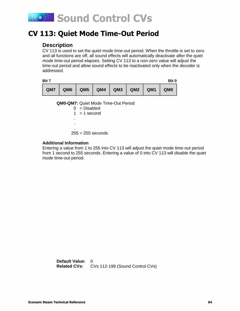
Description CV 113 is used to set the quiet mode time-out period. When the throttle is set to zero and all functions are off, all sound effects will automatically deactivate after the quiet mode time-out period elapses. Setting CV 113 to a non-zero value will adjust the time-out period and allow sound effects to be reactivated only when the decoder is addressed.
Bit 7 Bit 0
QM7 QM6 QM5 QM4 QM3 QM2 QM1 QM0
QM0-QM7: Quiet Mode Time-Out Period
0 = Disabled 1 = 1 second . . .
255 = 255 seconds
Additional Information Entering a value from 1 to 255 into CV 113 will adjust the quiet mode time-out period from 1 second to 255 seconds. Entering a value of 0 into CV 113 will disable the quiet mode time-out period.
Default Value: 0 Related CVs: CVs 112-199 (Sound Control CVs)
Sound Control CVs
Econami Steam Technical Reference 65
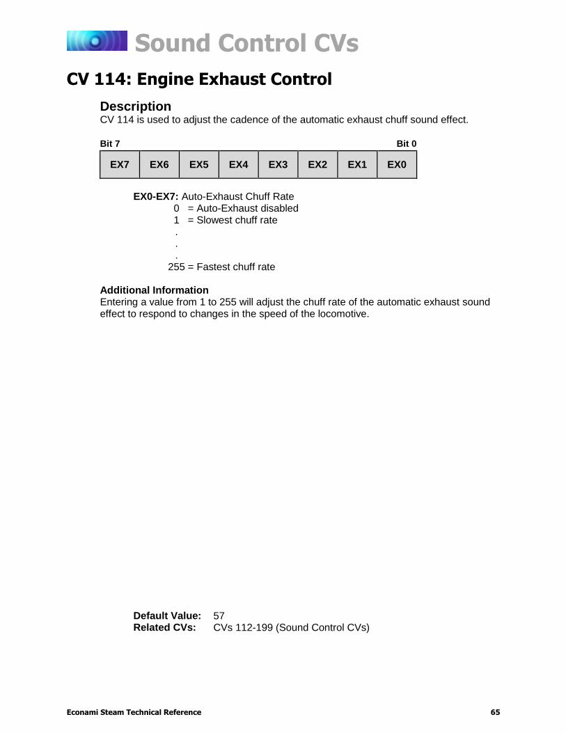
CV 114: Engine Exhaust Control
Description CV 114 is used to adjust the cadence of the automatic exhaust chuff sound effect.
Bit 7 Bit 0
EX7 EX6 EX5 EX4 EX3 EX2 EX1 EX0
EX0-EX7: Auto-Exhaust Chuff Rate
0 = Auto-Exhaust disabled 1 = Slowest chuff rate . . .
255 = Fastest chuff rate
Additional Information Entering a value from 1 to 255 will adjust the chuff rate of the automatic exhaust sound effect to respond to changes in the speed of the locomotive.
Default Value: 57 Related CVs: CVs 112-199 (Sound Control CVs)
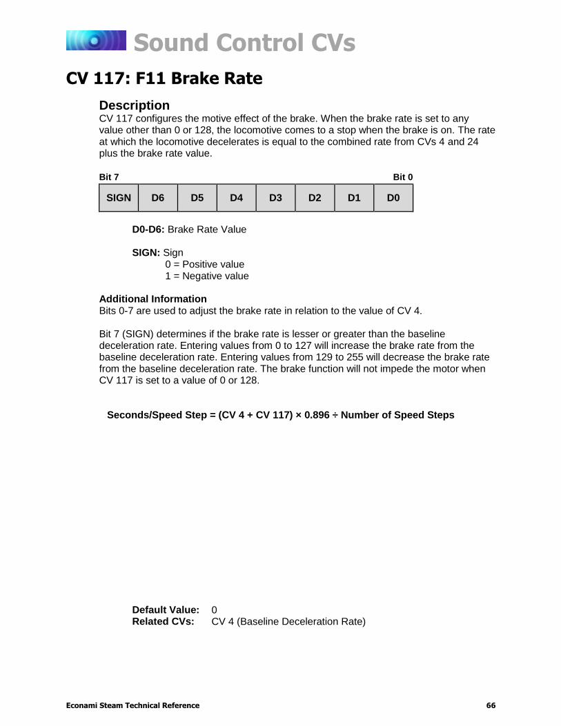
Sound Control CVs
Econami Steam Technical Reference 66
CV 117: F11 Brake Rate
Description CV 117 configures the motive effect of the brake. When the brake rate is set to any value other than 0 or 128, the locomotive comes to a stop when the brake is on. The rate at which the locomotive decelerates is equal to the combined rate from CVs 4 and 24 plus the brake rate value.
Bit 7 Bit 0
SIGN D6 D5 D4 D3 D2 D1 D0
D0-D6: Brake Rate Value
SIGN: Sign
0 = Positive value 1 = Negative value
Additional Information Bits 0-7 are used to adjust the brake rate in relation to the value of CV 4. Bit 7 (SIGN) determines if the brake rate is lesser or greater than the baseline deceleration rate. Entering values from 0 to 127 will increase the brake rate from the baseline deceleration rate. Entering values from 129 to 255 will decrease the brake rate from the baseline deceleration rate. The brake function will not impede the motor when CV 117 is set to a value of 0 or 128.
Seconds/Speed Step = (CV 4 + CV 117) × 0.896 ÷ Number of Speed Steps
Default Value: 0 Related CVs: CV 4 (Baseline Deceleration Rate)
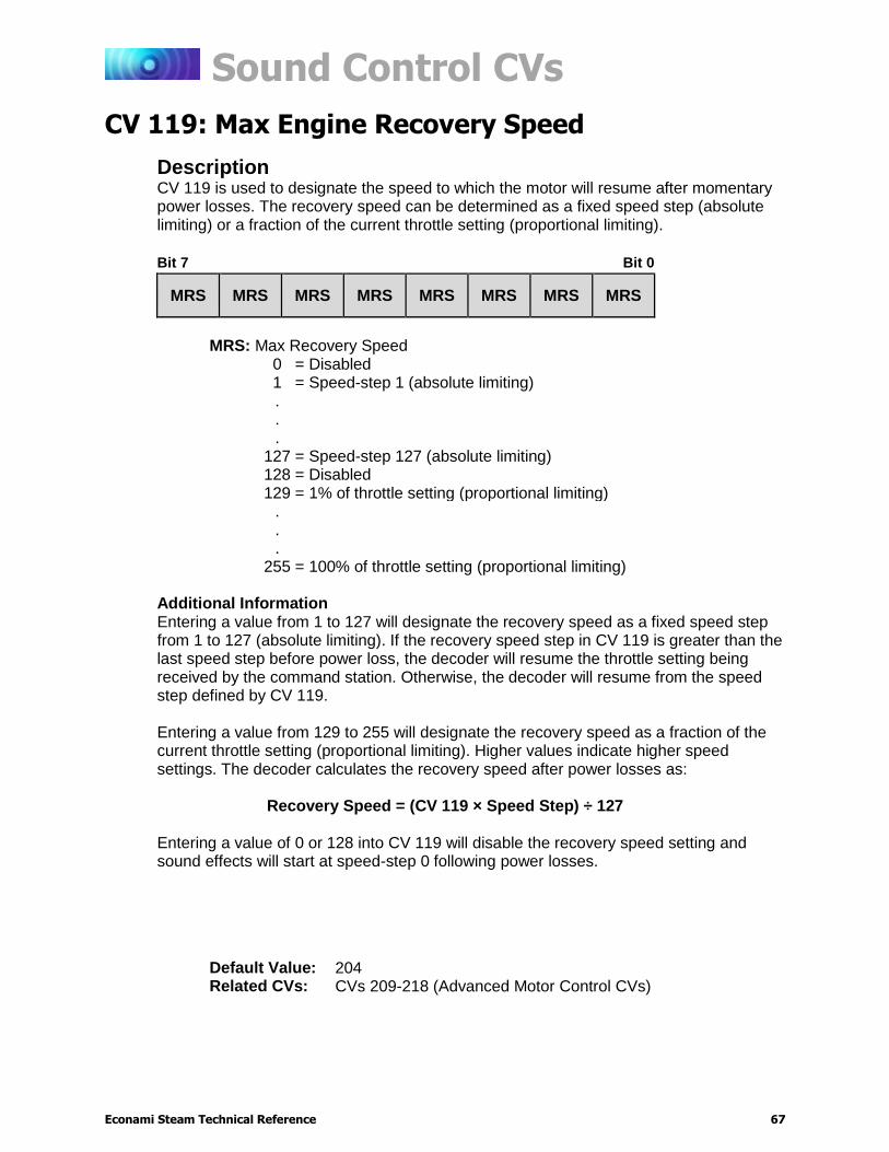
Sound Control CVs
Econami Steam Technical Reference 67
CV 119: Max Engine Recovery Speed
Description CV 119 is used to designate the speed to which the motor will resume after momentary power losses. The recovery speed can be determined as a fixed speed step (absolute limiting) or a fraction of the current throttle setting (proportional limiting).
Bit 7 Bit 0
MRS MRS MRS MRS MRS MRS MRS MRS
MRS: Max Recovery Speed
0 = Disabled 1 = Speed-step 1 (absolute limiting) . . .
127 = Speed-step 127 (absolute limiting) 128 = Disabled 129 = 1% of throttle setting (proportional limiting)
.
.
.
255 = 100% of throttle setting (proportional limiting)
Additional Information Entering a value from 1 to 127 will designate the recovery speed as a fixed speed step from 1 to 127 (absolute limiting). If the recovery speed step in CV 119 is greater than the last speed step before power loss, the decoder will resume the throttle setting being received by the command station. Otherwise, the decoder will resume from the speed step defined by CV 119. Entering a value from 129 to 255 will designate the recovery speed as a fraction of the current throttle setting (proportional limiting). Higher values indicate higher speed settings. The decoder calculates the recovery speed after power losses as:
Recovery Speed = (CV 119 × Speed Step) ÷ 127 Entering a value of 0 or 128 into CV 119 will disable the recovery speed setting and sound effects will start at speed-step 0 following power losses.
Default Value: 204 Related CVs: CVs 209-218 (Advanced Motor Control CVs)
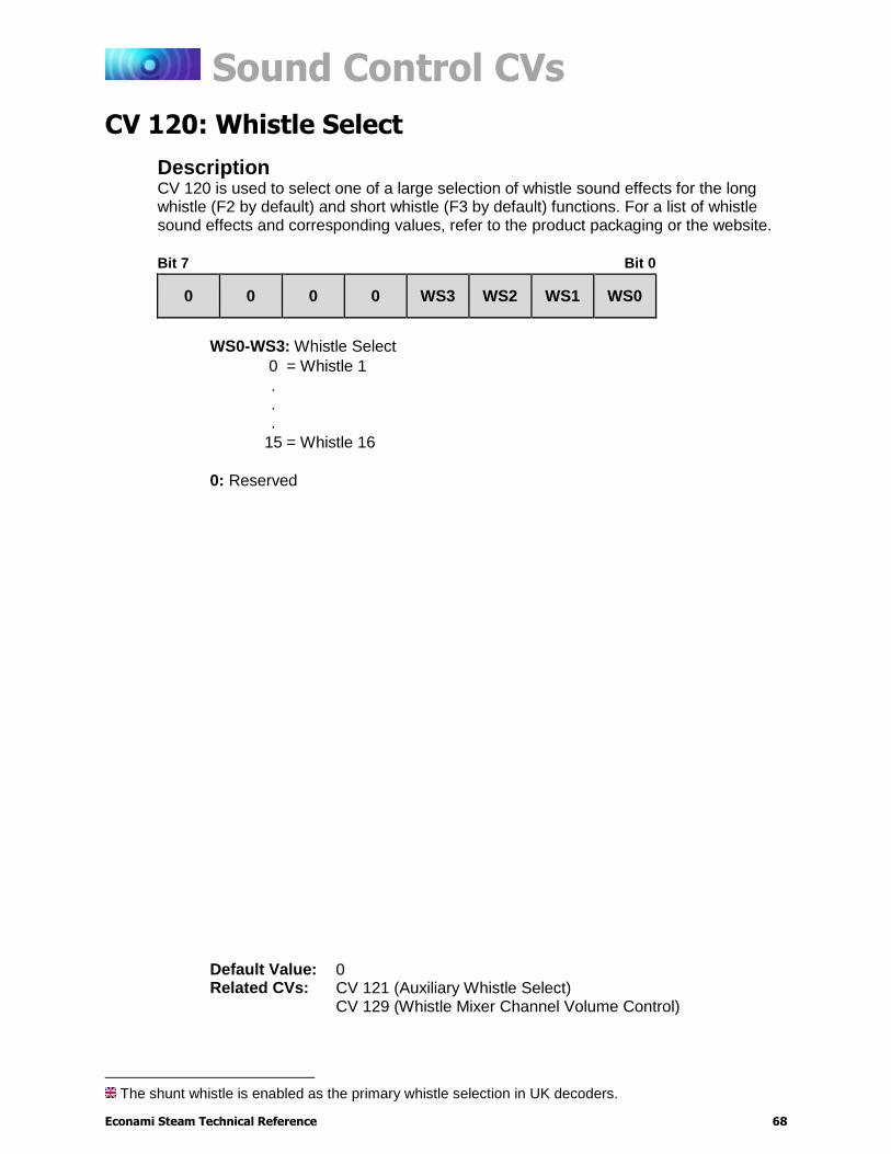
Sound Control CVs
Econami Steam Technical Reference 68
CV 120: Whistle Select1
Description CV 120 is used to select one of a large selection of whistle sound effects for the long whistle (F2 by default) and short whistle (F3 by default) functions. For a list of whistle sound effects and corresponding values, refer to the product packaging or the website.
Bit 7 Bit 0
0 0 0 0 WS3 WS2 WS1 WS0
WS0-WS3: Whistle Select
0 = Whistle 1
.
.
.
15 = Whistle 16
0: Reserved
The shunt whistle is enabled as the primary whistle selection in UK decoders.
Default Value: 0 Related CVs: CV 121 (Auxiliary Whistle Select)
CV 129 (Whistle Mixer Channel Volume Control)

Sound Control CVs
Econami Steam Technical Reference 69
CV 121: Auxiliary Whistle Select
Description CV 121 is used for selecting one of a large number of alternate whistle sound effects. For a list of whistle sound effects and corresponding values, refer to the product packaging or the website.
Bit 7 Bit 0
0 0 0 AWS4 AWS3 AWS2 AWS1 AWS0
AWS0-AWS4: Alternate Whistle Select
0 = Alternate Whistle disabled
1 = Replaces Short Whistle with Alternate Whistle 1
.
.
.
16 = Replaces Short Whistle with Alternate Whistle 16
0: Reserved
More Information Bits 0-5 (AWS0-AWS5) are used to select the alternate whistle sound effect. When the alternate whistle is enabled it disables the short whistle function. When the alternate whistle is enabled and the short whistle function is turned on, the long whistle function is used to activate the alternate whistle sound effect.
The main whistle is enabled as the auxiliary whistle selection in UK decoders.
Default Value: 0 Related CVs: CV 120 (Whistle Select)
CV 129 (Whistle Mixer Channel Volume Control)
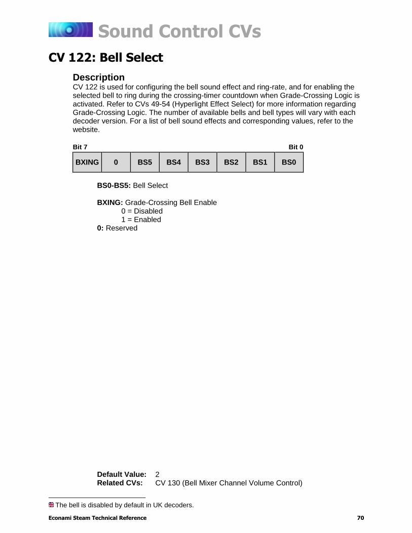
Sound Control CVs
Econami Steam Technical Reference 70
CV 122: Bell Select2
Description CV 122 is used for configuring the bell sound effect and ring-rate, and for enabling the selected bell to ring during the crossing-timer countdown when Grade-Crossing Logic is activated. Refer to CVs 49-54 (Hyperlight Effect Select) for more information regarding Grade-Crossing Logic. The number of available bells and bell types will vary with each decoder version. For a list of bell sound effects and corresponding values, refer to the website.
Bit 7 Bit 0
BXING 0 BS5 BS4 BS3 BS2 BS1 BS0
BS0-BS5: Bell Select
BXING: Grade-Crossing Bell Enable
0 = Disabled 1 = Enabled
0: Reserved
The bell is disabled by default in UK decoders.
Default Value: 2 Related CVs: CV 130 (Bell Mixer Channel Volume Control)
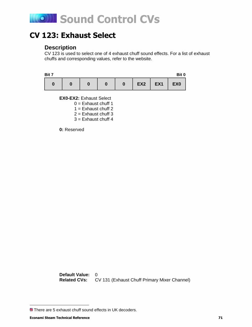
Sound Control CVs
Econami Steam Technical Reference 71
CV 123: Exhaust Select
Description CV 123 is used to select one of 4 exhaust chuff sound effects. For a list of exhaust chuffs and corresponding values, refer to the website.
Bit 7 Bit 0
0 0 0 0 0 EX2 EX1 EX0
EX0-EX2: Exhaust Select
0 = Exhaust chuff 1 1 = Exhaust chuff 2 2 = Exhaust chuff 3 3 = Exhaust chuff 4
0: Reserved
There are 5 exhaust chuff sound effects in UK decoders.
Default Value: 0 Related CVs: CV 131 (Exhaust Chuff Primary Mixer Channel)
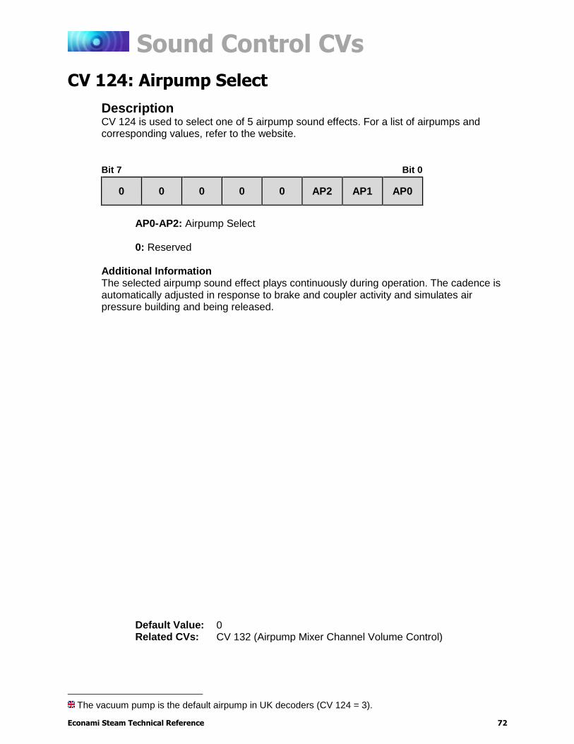
Sound Control CVs
Econami Steam Technical Reference 72
CV 124: Airpump Select
Description CV 124 is used to select one of 5 airpump sound effects. For a list of airpumps and corresponding values, refer to the website.
Bit 7 Bit 0
0 0 0 0 0 AP2 AP1 AP0
AP0-AP2: Airpump Select
0: Reserved
Additional Information The selected airpump sound effect plays continuously during operation. The cadence is automatically adjusted in response to brake and coupler activity and simulates air pressure building and being released.
The vacuum pump is the default airpump in UK decoders (CV 124 = 3).
Default Value: 0 Related CVs: CV 132 (Airpump Mixer Channel Volume Control)
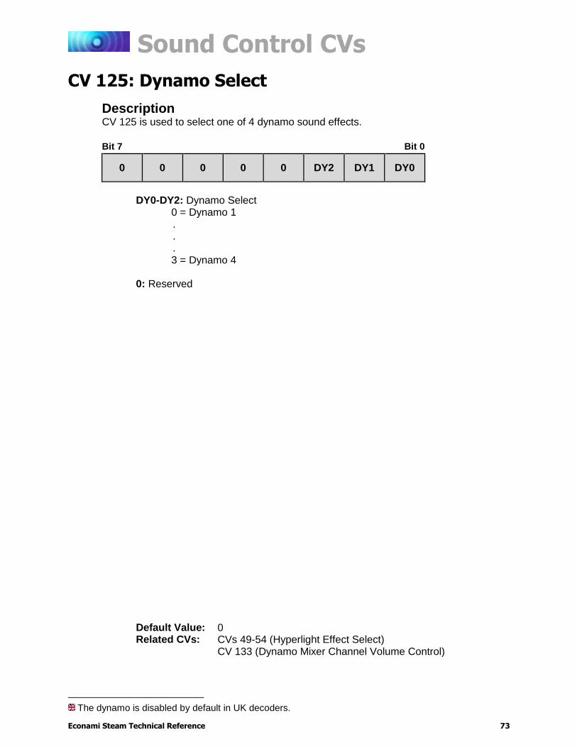
Sound Control CVs
Econami Steam Technical Reference 73
CV 125: Dynamo Select3
Description CV 125 is used to select one of 4 dynamo sound effects.
Bit 7 Bit 0
0 0 0 0 0 DY2 DY1 DY0
DY0-DY2: Dynamo Select
0 = Dynamo 1 . . .
3 = Dynamo 4 0: Reserved
The dynamo is disabled by default in UK decoders.
Default Value: 0 Related CVs: CVs 49-54 (Hyperlight Effect Select)
CV 133 (Dynamo Mixer Channel Volume Control)
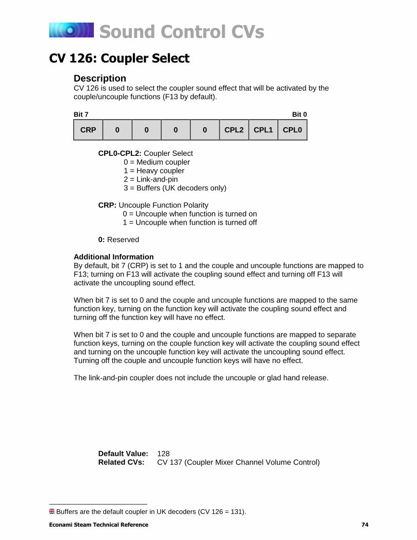
Sound Control CVs
Econami Steam Technical Reference 74
CV 126: Coupler Select4
Description CV 126 is used to select the coupler sound effect that will be activated by the couple/uncouple functions (F13 by default).
Bit 7 Bit 0
CRP 0 0 0 0 CPL2 CPL1 CPL0
CPL0-CPL2: Coupler Select
0 = Medium coupler 1 = Heavy coupler 2 = Link-and-pin 3 = Buffers (UK decoders only)
CRP: Uncouple Function Polarity
0 = Uncouple when function is turned on 1 = Uncouple when function is turned off
0: Reserved
Additional Information By default, bit 7 (CRP) is set to 1 and the couple and uncouple functions are mapped to F13; turning on F13 will activate the coupling sound effect and turning off F13 will activate the uncoupling sound effect. When bit 7 is set to 0 and the couple and uncouple functions are mapped to the same function key, turning on the function key will activate the coupling sound effect and turning off the function key will have no effect. When bit 7 is set to 0 and the couple and uncouple functions are mapped to separate function keys, turning on the couple function key will activate the coupling sound effect and turning on the uncouple function key will activate the uncoupling sound effect. Turning off the couple and uncouple function keys will have no effect. The link-and-pin coupler does not include the uncouple or glad hand release.
Buffers are the default coupler in UK decoders (CV 126 = 131).
Default Value: 128 Related CVs: CV 137 (Coupler Mixer Channel Volume Control)
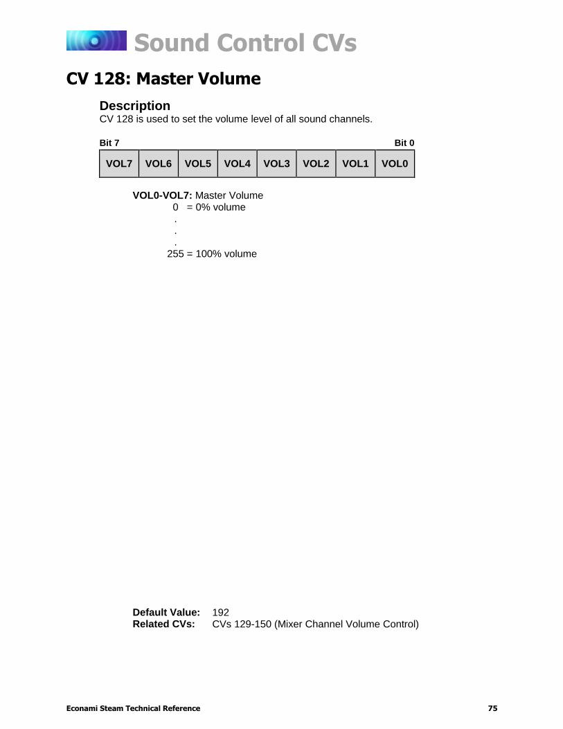
Sound Control CVs
Econami Steam Technical Reference 75
CV 128: Master Volume
Description CV 128 is used to set the volume level of all sound channels.
Bit 7 Bit 0
VOL7 VOL6 VOL5 VOL4 VOL3 VOL2 VOL1 VOL0
VOL0-VOL7: Master Volume
0 = 0% volume . . .
255 = 100% volume
Default Value: 192 Related CVs: CVs 129-150 (Mixer Channel Volume Control)
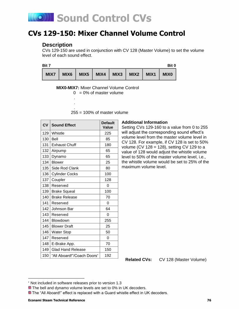
Sound Control CVs
Econami Steam Technical Reference 76
CVs 129-150: Mixer Channel Volume Control
Description CVs 129-150 are used in conjunction with CV 128 (Master Volume) to set the volume level of each sound effect.
Bit 7 Bit 0
MIX7 MIX6 MIX5 MIX4 MIX3 MIX2 MIX1 MIX0
MIX0-MIX7: Mixer Channel Volume Control
0 = 0% of master volume . . .
255 = 100% of master volume
Additional Information Setting CVs 129-160 to a value from 0 to 255 will adjust the corresponding sound effect’s volume level from the master volume level in CV 128. For example, if CV 128 is set to 50% volume (CV 128 = 128), setting CV 129 to a value of 128 would adjust the whistle volume level to 50% of the master volume level, i.e., the whistle volume would be set to 25% of the maximum volume level.
Not included in software releases prior to version 1.3
The bell and dynamo volume levels are set to 0% in UK decoders.
The “All Aboard!” effect is replaced with a Guard whistle effect in UK decoders.
CV Sound Effect Default Value
129 Whistle 225
130 Bell 85
131 Exhaust Chuff 180
132 Airpump 65
133 Dynamo 65
134 Blower 25
135 Side Rod Clank 80
136 Cylinder Cocks 100
137 Coupler 128
138 Reserved 0
139 Brake Squeal 100
140 Brake Release 70
141 Reserved 0
142 Johnson Bar 64
143 Reserved 0
144 Blowdown 255
145 Blower Draft 25
146 Water Stop 50
147 Reserved 0
148 E-Brake App. 70
149 Glad Hand Release 150
150 “All Aboard!”/Coach Doors 192 Related CVs: CV 128 (Master Volume)
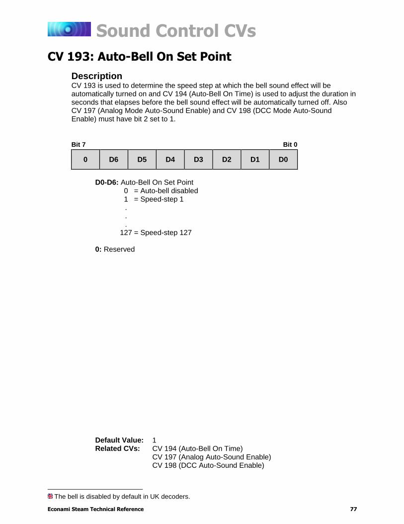
Sound Control CVs
Econami Steam Technical Reference 77
CV 193: Auto-Bell On Set Point5
Description CV 193 is used to determine the speed step at which the bell sound effect will be automatically turned on and CV 194 (Auto-Bell On Time) is used to adjust the duration in seconds that elapses before the bell sound effect will be automatically turned off. Also CV 197 (Analog Mode Auto-Sound Enable) and CV 198 (DCC Mode Auto-Sound Enable) must have bit 2 set to 1.
Bit 7 Bit 0
0 D6 D5 D4 D3 D2 D1 D0
D0-D6: Auto-Bell On Set Point
0 = Auto-bell disabled 1 = Speed-step 1 . . .
127 = Speed-step 127 0: Reserved
The bell is disabled by default in UK decoders.
Default Value: 1 Related CVs: CV 194 (Auto-Bell On Time)
CV 197 (Analog Auto-Sound Enable) CV 198 (DCC Auto-Sound Enable)
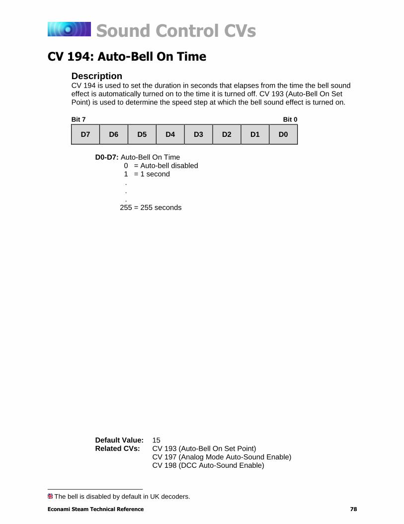
Sound Control CVs
Econami Steam Technical Reference 78
CV 194: Auto-Bell On Time6
Description CV 194 is used to set the duration in seconds that elapses from the time the bell sound effect is automatically turned on to the time it is turned off. CV 193 (Auto-Bell On Set Point) is used to determine the speed step at which the bell sound effect is turned on.
Bit 7 Bit 0
D7 D6 D5 D4 D3 D2 D1 D0
D0-D7: Auto-Bell On Time
0 = Auto-bell disabled 1 = 1 second . . .
255 = 255 seconds
The bell is disabled by default in UK decoders.
Default Value: 15 Related CVs: CV 193 (Auto-Bell On Set Point)
CV 197 (Analog Mode Auto-Sound Enable) CV 198 (DCC Auto-Sound Enable)
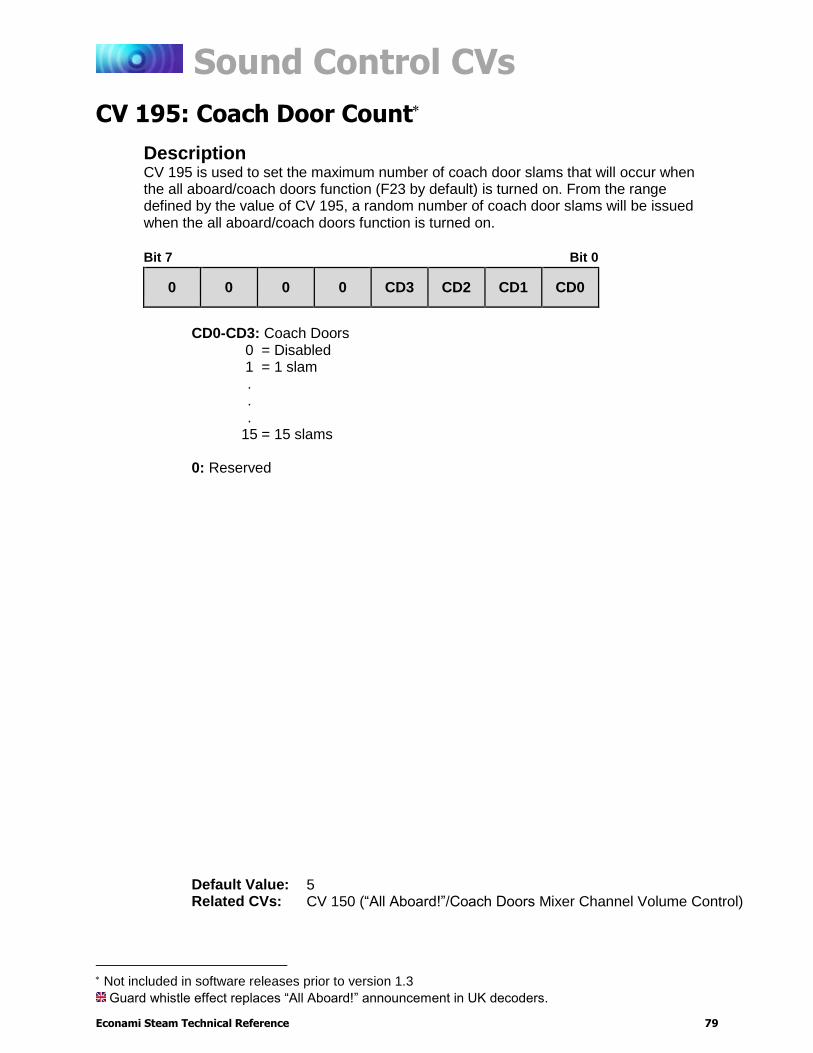
Sound Control CVs
Econami Steam Technical Reference 79
CV 195: Coach Door Count
Description CV 195 is used to set the maximum number of coach door slams that will occur when the all aboard/coach doors function (F23 by default) is turned on. From the range defined by the value of CV 195, a random number of coach door slams will be issued when the all aboard/coach doors function is turned on.
Bit 7 Bit 0
0 0 0 0 CD3 CD2 CD1 CD0
CD0-CD3: Coach Doors
0 = Disabled 1 = 1 slam . . .
15 = 15 slams 0: Reserved
Not included in software releases prior to version 1.3
Guard whistle effect replaces “All Aboard!” announcement in UK decoders.
Default Value: 5 Related CVs: CV 150 (“All Aboard!”/Coach Doors Mixer Channel Volume Control)
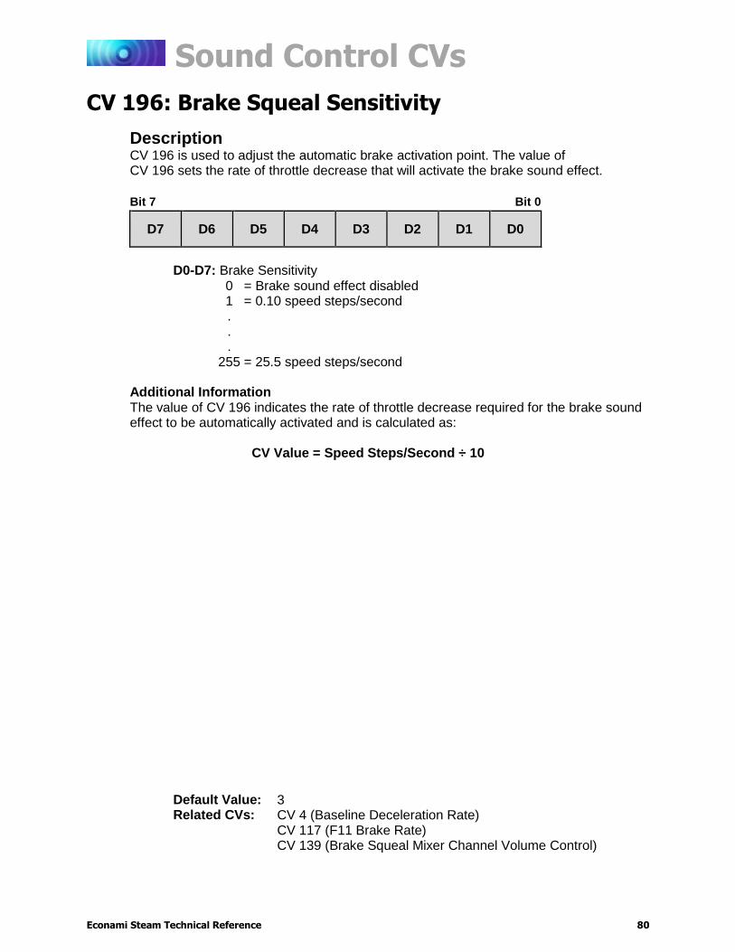
Sound Control CVs
Econami Steam Technical Reference 80
CV 196: Brake Squeal Sensitivity
Description CV 196 is used to adjust the automatic brake activation point. The value of CV 196 sets the rate of throttle decrease that will activate the brake sound effect.
Bit 7 Bit 0
D7 D6 D5 D4 D3 D2 D1 D0
D0-D7: Brake Sensitivity
0 = Brake sound effect disabled 1 = 0.10 speed steps/second . . .
255 = 25.5 speed steps/second Additional Information The value of CV 196 indicates the rate of throttle decrease required for the brake sound effect to be automatically activated and is calculated as:
CV Value = Speed Steps/Second ÷ 10
Default Value: 3 Related CVs: CV 4 (Baseline Deceleration Rate)
CV 117 (F11 Brake Rate) CV 139 (Brake Squeal Mixer Channel Volume Control)
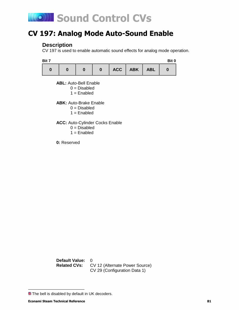
Sound Control CVs
Econami Steam Technical Reference 81
CV 197: Analog Mode Auto-Sound Enable7
Description CV 197 is used to enable automatic sound effects for analog mode operation.
Bit 7 Bit 0
0 0 0 0 ACC ABK ABL 0
ABL: Auto-Bell Enable
0 = Disabled 1 = Enabled
ABK: Auto-Brake Enable
0 = Disabled 1 = Enabled
ACC: Auto-Cylinder Cocks Enable 0 = Disabled 1 = Enabled
0: Reserved
The bell is disabled by default in UK decoders.
Default Value: 0 Related CVs: CV 12 (Alternate Power Source)
CV 29 (Configuration Data 1)
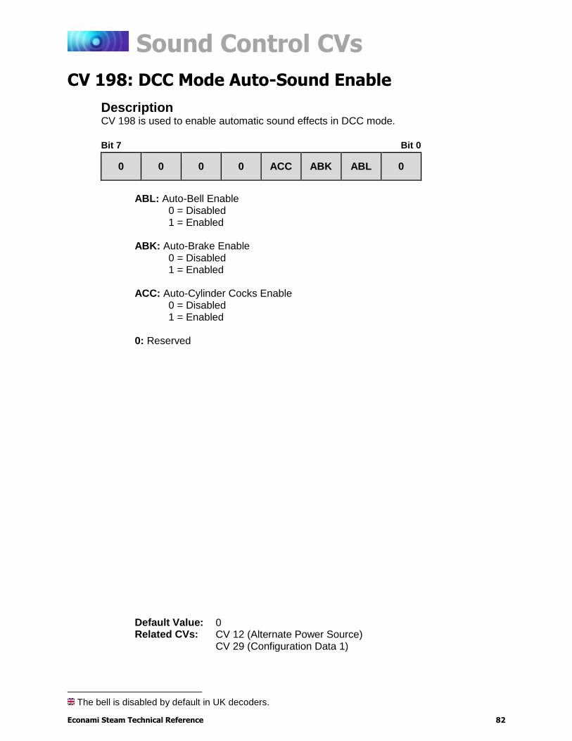
Sound Control CVs
Econami Steam Technical Reference 82
CV 198: DCC Mode Auto-Sound Enable8
Description CV 198 is used to enable automatic sound effects in DCC mode.
Bit 7 Bit 0
0 0 0 0 ACC ABK ABL 0
ABL: Auto-Bell Enable
0 = Disabled 1 = Enabled
ABK: Auto-Brake Enable
0 = Disabled 1 = Enabled
ACC: Auto-Cylinder Cocks Enable 0 = Disabled 1 = Enabled
0: Reserved
The bell is disabled by default in UK decoders.
Default Value: 0 Related CVs: CV 12 (Alternate Power Source)
CV 29 (Configuration Data 1)
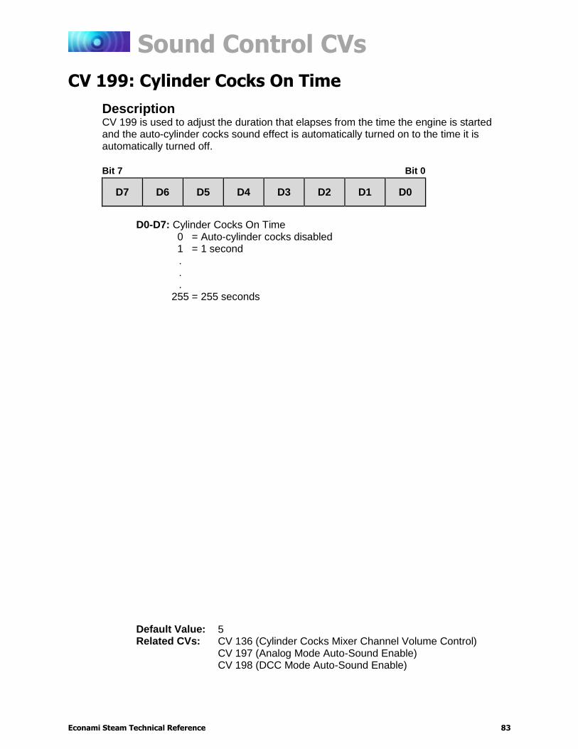
Sound Control CVs
Econami Steam Technical Reference 83
CV 199: Cylinder Cocks On Time
Description CV 199 is used to adjust the duration that elapses from the time the engine is started and the auto-cylinder cocks sound effect is automatically turned on to the time it is automatically turned off.
Bit 7 Bit 0
D7 D6 D5 D4 D3 D2 D1 D0
D0-D7: Cylinder Cocks On Time
0 = Auto-cylinder cocks disabled 1 = 1 second . . .
255 = 255 seconds
Default Value: 5 Related CVs: CV 136 (Cylinder Cocks Mixer Channel Volume Control)
CV 197 (Analog Mode Auto-Sound Enable) CV 198 (DCC Mode Auto-Sound Enable)
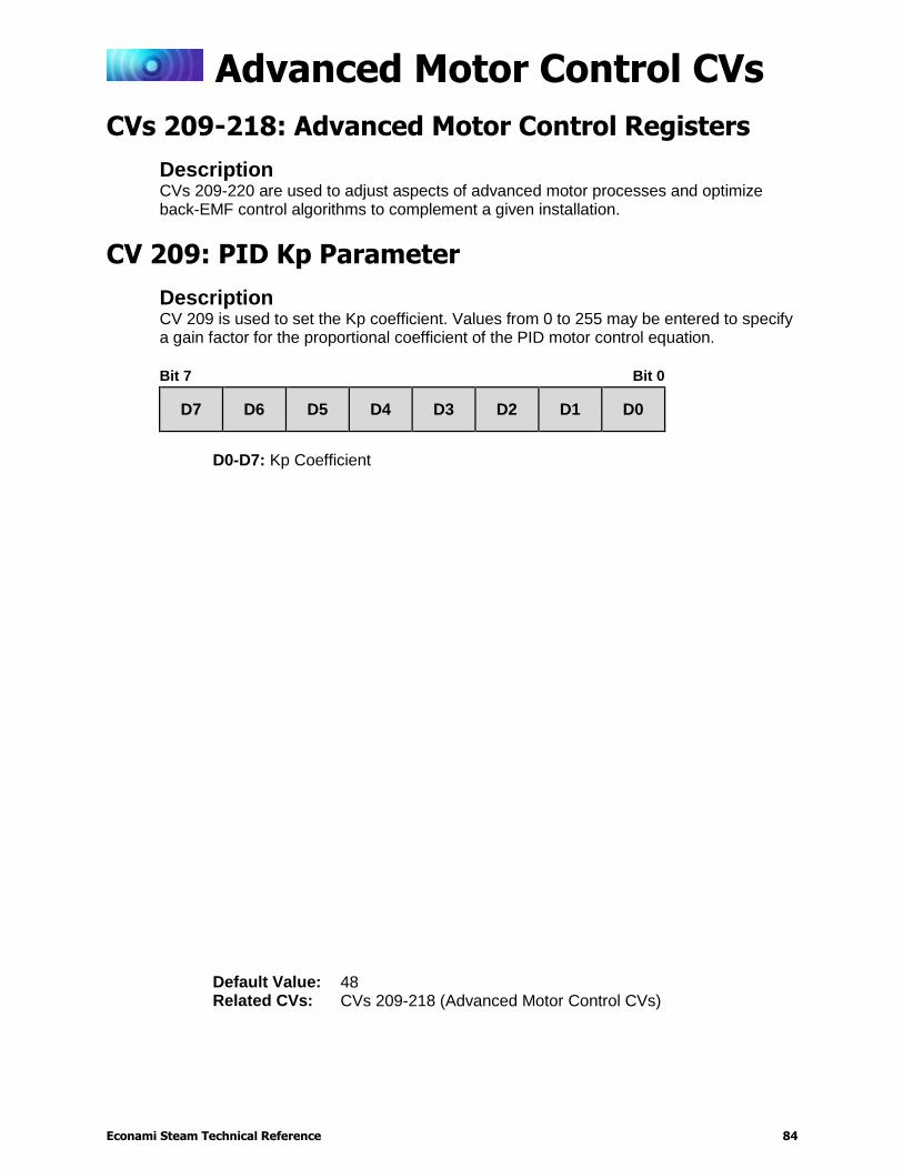
Advanced Motor Control CVs
Econami Steam Technical Reference 84
Advanced Motor Control CVs
CVs 209-218: Advanced Motor Control Registers
Description CVs 209-220 are used to adjust aspects of advanced motor processes and optimize back-EMF control algorithms to complement a given installation.
CV 209: PID Kp Parameter
Description CV 209 is used to set the Kp coefficient. Values from 0 to 255 may be entered to specify a gain factor for the proportional coefficient of the PID motor control equation.
Bit 7 Bit 0
D7 D6 D5 D4 D3 D2 D1 D0
D0-D7: Kp Coefficient
Default Value: 48 Related CVs: CVs 209-218 (Advanced Motor Control CVs)
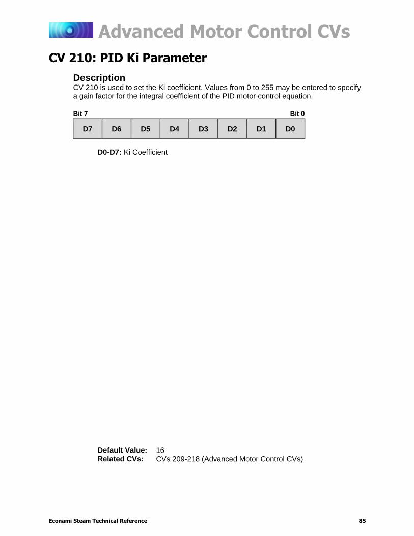
Advanced Motor Control CVs
Econami Steam Technical Reference 85
CV 210: PID Ki Parameter
Description CV 210 is used to set the Ki coefficient. Values from 0 to 255 may be entered to specify a gain factor for the integral coefficient of the PID motor control equation.
Bit 7 Bit 0
D7 D6 D5 D4 D3 D2 D1 D0
D0-D7: Ki Coefficient
Default Value: 16 Related CVs: CVs 209-218 (Advanced Motor Control CVs)
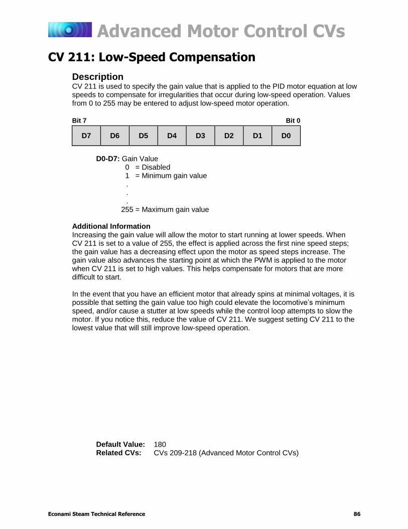
Advanced Motor Control CVs
Econami Steam Technical Reference 86
CV 211: Low-Speed Compensation
Description
CV 211 is used to specify the gain value that is applied to the PID motor equation at low speeds to compensate for irregularities that occur during low-speed operation. Values from 0 to 255 may be entered to adjust low-speed motor operation.
Bit 7 Bit 0
D7 D6 D5 D4 D3 D2 D1 D0
D0-D7: Gain Value
0 = Disabled 1 = Minimum gain value . . .
255 = Maximum gain value
Additional Information Increasing the gain value will allow the motor to start running at lower speeds. When CV 211 is set to a value of 255, the effect is applied across the first nine speed steps; the gain value has a decreasing effect upon the motor as speed steps increase. The gain value also advances the starting point at which the PWM is applied to the motor when CV 211 is set to high values. This helps compensate for motors that are more difficult to start. In the event that you have an efficient motor that already spins at minimal voltages, it is possible that setting the gain value too high could elevate the locomotive’s minimum speed, and/or cause a stutter at low speeds while the control loop attempts to slow the motor. If you notice this, reduce the value of CV 211. We suggest setting CV 211 to the lowest value that will still improve low-speed operation.
Default Value: 180 Related CVs: CVs 209-218 (Advanced Motor Control CVs)
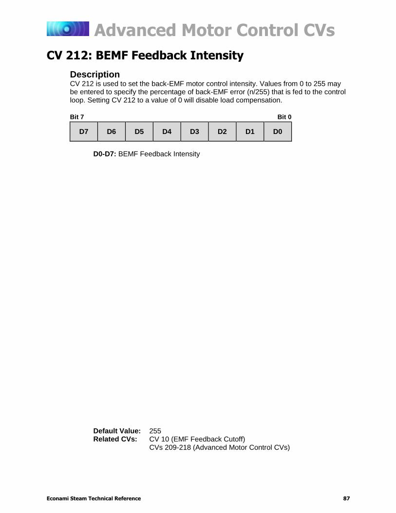
Advanced Motor Control CVs
Econami Steam Technical Reference 87
CV 212: BEMF Feedback Intensity
Description CV 212 is used to set the back-EMF motor control intensity. Values from 0 to 255 may be entered to specify the percentage of back-EMF error (n/255) that is fed to the control loop. Setting CV 212 to a value of 0 will disable load compensation.
Bit 7 Bit 0
D7 D6 D5 D4 D3 D2 D1 D0
D0-D7: BEMF Feedback Intensity
Default Value: 255 Related CVs: CV 10 (EMF Feedback Cutoff)
CVs 209-218 (Advanced Motor Control CVs)

Advanced Motor Control CVs
Econami Steam Technical Reference 88
CV 213: BEMF Sample Period
Description CV 213 is used to set the back-EMF sample period.
Bit 7 Bit 0
0 0 0 D4 D3 D2 D1 D0
D0-D4: BEMF Sample Period 0: Reserved
Additional Information Additional Information Values from 0 to 31 may be entered into bits 0-4 (D0-D4) to set the BEMF Sample Period that specifies the time period in mS (milliseconds) between measurements.
Default Value: 9 Related CVs: CVs 209-218 (Advanced Motor Control CVs)
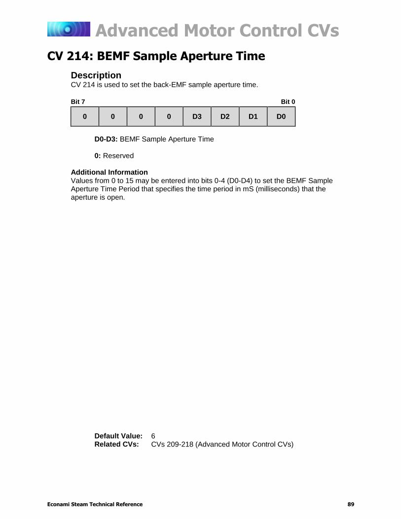
Advanced Motor Control CVs
Econami Steam Technical Reference 89
CV 214: BEMF Sample Aperture Time
Description CV 214 is used to set the back-EMF sample aperture time.
Bit 7 Bit 0
0 0 0 0 D3 D2 D1 D0
D0-D3: BEMF Sample Aperture Time 0: Reserved
Additional Information Values from 0 to 15 may be entered into bits 0-4 (D0-D4) to set the BEMF Sample Aperture Time Period that specifies the time period in mS (milliseconds) that the aperture is open.
Default Value: 6 Related CVs: CVs 209-218 (Advanced Motor Control CVs)
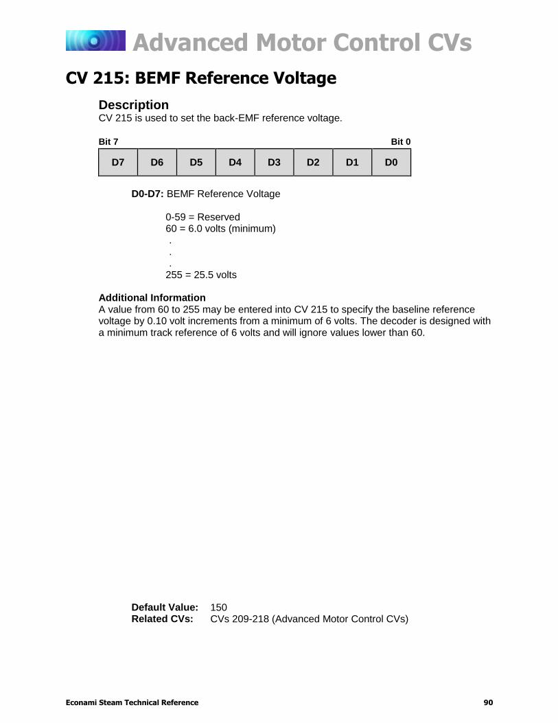
Advanced Motor Control CVs
Econami Steam Technical Reference 90
CV 215: BEMF Reference Voltage
Description CV 215 is used to set the back-EMF reference voltage.
Bit 7 Bit 0
D7 D6 D5 D4 D3 D2 D1 D0
D0-D7: BEMF Reference Voltage
0-59 = Reserved 60 = 6.0 volts (minimum) . . .
255 = 25.5 volts Additional Information A value from 60 to 255 may be entered into CV 215 to specify the baseline reference voltage by 0.10 volt increments from a minimum of 6 volts. The decoder is designed with a minimum track reference of 6 volts and will ignore values lower than 60.
Default Value: 150 Related CVs: CVs 209-218 (Advanced Motor Control CVs)

Advanced Motor Control CVs
Econami Steam Technical Reference 91
CV 216: Motor Speed Step Deadband
Description CV 216 is used to determine the speed step at which voltage is first applied to the motor output to put the locomotive into motion.
Bit 7 Bit 0
0 D6 D5 D4 D3 D2 D1 D0
D0-D6: Motor Speed Step Deadband
0 = Disabled 1 = Speed-step 1 . . .
127 = Speed-step 127
0: Reserved
Not included in software releases prior to version 1.3
Default Value: 0 Related CVs: CVs 209-218 (Advanced Motor Control CVs)
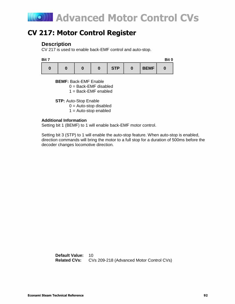
Advanced Motor Control CVs
Econami Steam Technical Reference 92
CV 217: Motor Control Register
Description CV 217 is used to enable back-EMF control and auto-stop.
Bit 7 Bit 0
0 0 0 0 STP 0 BEMF 0
BEMF: Back-EMF Enable
0 = Back-EMF disabled 1 = Back-EMF enabled
STP: Auto-Stop Enable
0 = Auto-stop disabled 1 = Auto-stop enabled
Additional Information Setting bit 1 (BEMF) to 1 will enable back-EMF motor control. Setting bit 3 (STP) to 1 will enable the auto-stop feature. When auto-stop is enabled, direction commands will bring the motor to a full stop for a duration of 500ms before the decoder changes locomotive direction.
Default Value: 10 Related CVs: CVs 209-218 (Advanced Motor Control CVs)
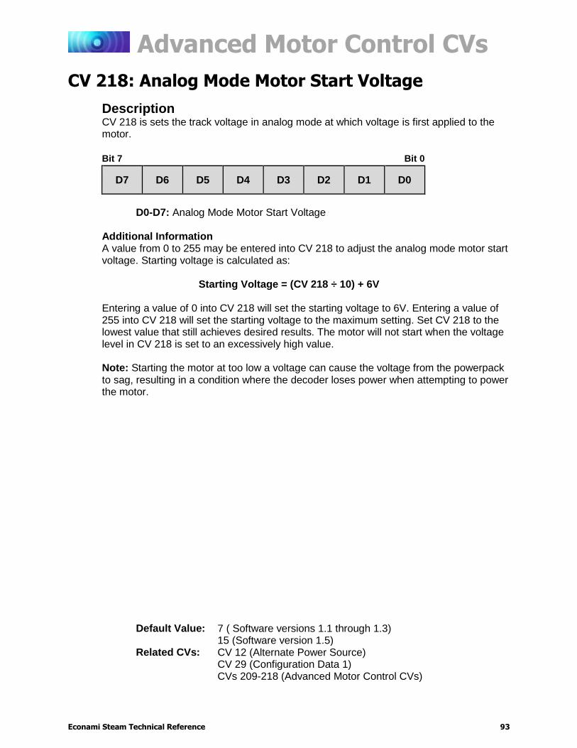
Advanced Motor Control CVs
Econami Steam Technical Reference 93
CV 218: Analog Mode Motor Start Voltage
Description CV 218 is sets the track voltage in analog mode at which voltage is first applied to the motor.
Bit 7 Bit 0
D7 D6 D5 D4 D3 D2 D1 D0
D0-D7: Analog Mode Motor Start Voltage
Additional Information A value from 0 to 255 may be entered into CV 218 to adjust the analog mode motor start voltage. Starting voltage is calculated as:
Starting Voltage = (CV 218 ÷ 10) + 6V
Entering a value of 0 into CV 218 will set the starting voltage to 6V. Entering a value of 255 into CV 218 will set the starting voltage to the maximum setting. Set CV 218 to the lowest value that still achieves desired results. The motor will not start when the voltage level in CV 218 is set to an excessively high value. Note: Starting the motor at too low a voltage can cause the voltage from the powerpack to sag, resulting in a condition where the decoder loses power when attempting to power the motor.
Default Value: 7 ( Software versions 1.1 through 1.3) 15 (Software version 1.5)
Related CVs: CV 12 (Alternate Power Source) CV 29 (Configuration Data 1) CVs 209-218 (Advanced Motor Control CVs)
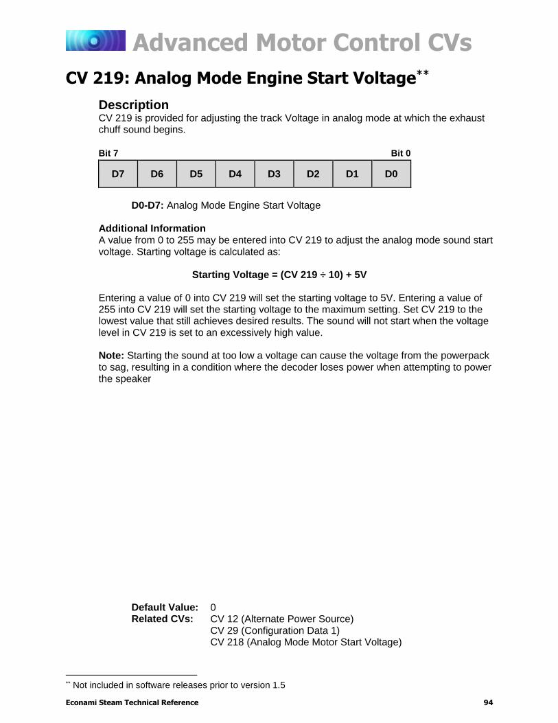
Advanced Motor Control CVs
Econami Steam Technical Reference 94
CV 219: Analog Mode Engine Start Voltage**
Description CV 219 is provided for adjusting the track Voltage in analog mode at which the exhaust chuff sound begins.
Bit 7 Bit 0
D7 D6 D5 D4 D3 D2 D1 D0
D0-D7: Analog Mode Engine Start Voltage
Additional Information A value from 0 to 255 may be entered into CV 219 to adjust the analog mode sound start voltage. Starting voltage is calculated as:
Starting Voltage = (CV 219 ÷ 10) + 5V
Entering a value of 0 into CV 219 will set the starting voltage to 5V. Entering a value of 255 into CV 219 will set the starting voltage to the maximum setting. Set CV 219 to the lowest value that still achieves desired results. The sound will not start when the voltage level in CV 219 is set to an excessively high value. Note: Starting the sound at too low a voltage can cause the voltage from the powerpack to sag, resulting in a condition where the decoder loses power when attempting to power the speaker
** Not included in software releases prior to version 1.5
Default Value: 0 Related CVs: CV 12 (Alternate Power Source)
CV 29 (Configuration Data 1) CV 218 (Analog Mode Motor Start Voltage)
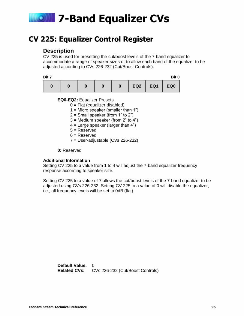
7-Band Equalizer CVs
Econami Steam Technical Reference 95
7-Band Equalizer CVs
CV 225: Equalizer Control Register
Description CV 225 is used for presetting the cut/boost levels of the 7-band equalizer to accommodate a range of speaker sizes or to allow each band of the equalizer to be adjusted according to CVs 226-232 (Cut/Boost Controls).
Bit 7 Bit 0
0 0 0 0 0 EQ2 EQ1 EQ0
EQ0-EQ2: Equalizer Presets
0 = Flat (equalizer disabled) 1 = Micro speaker (smaller than 1”) 2 = Small speaker (from 1” to 2”) 3 = Medium speaker (from 2” to 4”) 4 = Large speaker (larger than 4”) 5 = Reserved 6 = Reserved 7 = User-adjustable (CVs 226-232)
0: Reserved
Additional Information Setting CV 225 to a value from 1 to 4 will adjust the 7-band equalizer frequency response according to speaker size. Setting CV 225 to a value of 7 allows the cut/boost levels of the 7-band equalizer to be adjusted using CVs 226-232. Setting CV 225 to a value of 0 will disable the equalizer, i.e., all frequency levels will be set to 0dB (flat).
Default Value: 0 Related CVs: CVs 226-232 (Cut/Boost Controls)

7-Band Equalizer CVs
Econami Steam Technical Reference 96
CVs 226-232: Cut/Boost Controls
Description The frequency levels of the equalizer are divided into seven bands, ranging from 62Hz to 4kHz. Modify each band’s frequency response from -12dB (cut) to +12dB (boost) by entering values from 0 to 255 into the following CVs:
CV 226: 62Hz Cut/Boost
CV 227: 125Hz Cut/Boost
CV 228: 250Hz Cut/Boost
CV 229: 500Hz Cut/Boost
CV 230: 1kHz Cut/Boost
CV 231: 2kHz Cut/Boost
CV 232: 4kHz Cut/Boost
Bit 7 Bit 0
D7 D6 D5 D4 D3 D2 D1 D0
D0-D7: Cut/Boost Level
0 = -12dB cut
.
.
.
127 = -0.95dB cut
128 = 0dB (flat)
129 = +0.95dB boost
.
.
.
255 = +12dB boost
Note: A value of 7 must be entered into CV 225 (Equalizer Control Register) to enable CVs 226-232 (Cut/Boost Controls).
Default Value: CV 226 = 128 CV 227 = 128 CV 228 = 128 CV 229 = 128 CV 230 = 128 CV 231 = 128 CV 232 = 128
Related CVs: CVs 224-236 (Audio Control CVs)
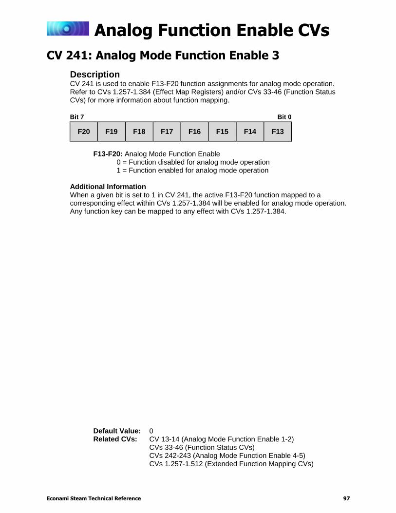
Analog Function Enable CVs
Econami Steam Technical Reference 97
Analog Function Enable CVs
CV 241: Analog Mode Function Enable 3
Description CV 241 is used to enable F13-F20 function assignments for analog mode operation. Refer to CVs 1.257-1.384 (Effect Map Registers) and/or CVs 33-46 (Function Status CVs) for more information about function mapping.
Bit 7 Bit 0
F20 F19 F18 F17 F16 F15 F14 F13
F13-F20: Analog Mode Function Enable
0 = Function disabled for analog mode operation 1 = Function enabled for analog mode operation
Additional Information When a given bit is set to 1 in CV 241, the active F13-F20 function mapped to a corresponding effect within CVs 1.257-1.384 will be enabled for analog mode operation. Any function key can be mapped to any effect with CVs 1.257-1.384.
Default Value: 0 Related CVs: CV 13-14 (Analog Mode Function Enable 1-2)
CVs 33-46 (Function Status CVs) CVs 242-243 (Analog Mode Function Enable 4-5) CVs 1.257-1.512 (Extended Function Mapping CVs)
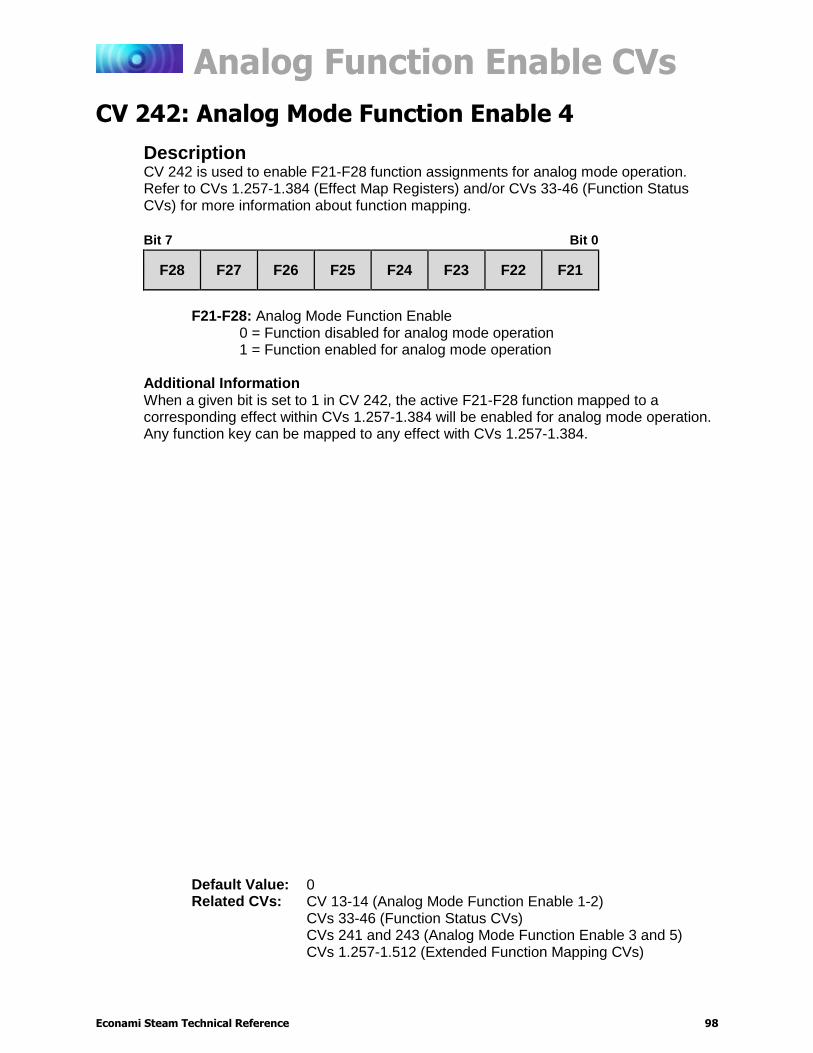
Analog Function Enable CVs
Econami Steam Technical Reference 98
CV 242: Analog Mode Function Enable 4
Description CV 242 is used to enable F21-F28 function assignments for analog mode operation. Refer to CVs 1.257-1.384 (Effect Map Registers) and/or CVs 33-46 (Function Status CVs) for more information about function mapping.
Bit 7 Bit 0
F28 F27 F26 F25 F24 F23 F22 F21
F21-F28: Analog Mode Function Enable
0 = Function disabled for analog mode operation 1 = Function enabled for analog mode operation
Additional Information When a given bit is set to 1 in CV 242, the active F21-F28 function mapped to a corresponding effect within CVs 1.257-1.384 will be enabled for analog mode operation. Any function key can be mapped to any effect with CVs 1.257-1.384.
Default Value: 0 Related CVs: CV 13-14 (Analog Mode Function Enable 1-2)
CVs 33-46 (Function Status CVs) CVs 241 and 243 (Analog Mode Function Enable 3 and 5) CVs 1.257-1.512 (Extended Function Mapping CVs)
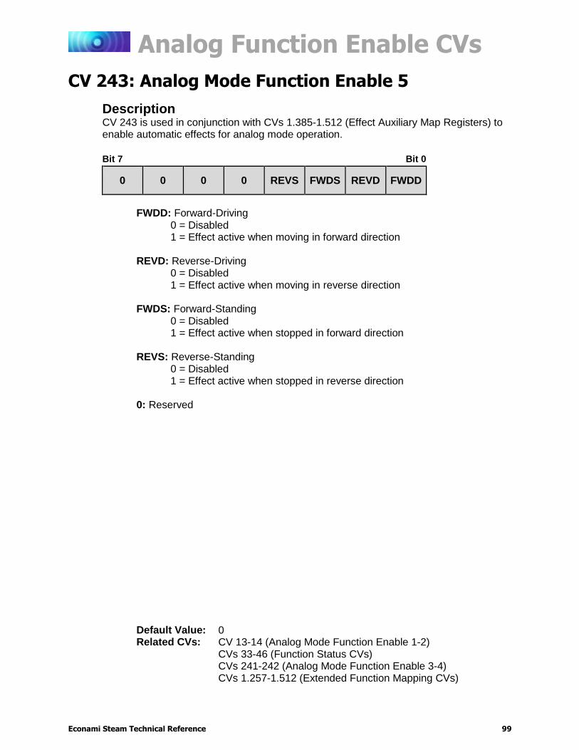
Analog Function Enable CVs
Econami Steam Technical Reference 99
CV 243: Analog Mode Function Enable 5
Description CV 243 is used in conjunction with CVs 1.385-1.512 (Effect Auxiliary Map Registers) to enable automatic effects for analog mode operation.
Bit 7 Bit 0
0 0 0 0 REVS FWDS REVD FWDD
FWDD: Forward-Driving
0 = Disabled 1 = Effect active when moving in forward direction
REVD: Reverse-Driving 0 = Disabled 1 = Effect active when moving in reverse direction
FWDS: Forward-Standing 0 = Disabled 1 = Effect active when stopped in forward direction
REVS: Reverse-Standing 0 = Disabled 1 = Effect active when stopped in reverse direction
0: Reserved
Default Value: 0 Related CVs: CV 13-14 (Analog Mode Function Enable 1-2)
CVs 33-46 (Function Status CVs) CVs 241-242 (Analog Mode Function Enable 3-4) CVs 1.257-1.512 (Extended Function Mapping CVs)
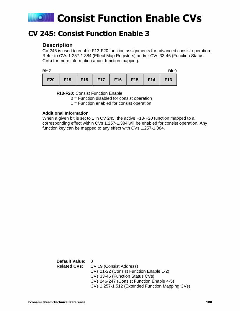
Consist Function Enable CVs
Econami Steam Technical Reference 100
Consist Function Enable CVs
CV 245: Consist Function Enable 3
Description CV 245 is used to enable F13-F20 function assignments for advanced consist operation. Refer to CVs 1.257-1.384 (Effect Map Registers) and/or CVs 33-46 (Function Status CVs) for more information about function mapping.
Bit 7 Bit 0
F20 F19 F18 F17 F16 F15 F14 F13
F13-F20: Consist Function Enable
0 = Function disabled for consist operation 1 = Function enabled for consist operation
Additional Information When a given bit is set to 1 in CV 245, the active F13-F20 function mapped to a corresponding effect within CVs 1.257-1.384 will be enabled for consist operation. Any function key can be mapped to any effect with CVs 1.257-1.384.
Default Value: 0 Related CVs: CV 19 (Consist Address)
CVs 21-22 (Consist Function Enable 1-2) CVs 33-46 (Function Status CVs) CVs 246-247 (Consist Function Enable 4-5) CVs 1.257-1.512 (Extended Function Mapping CVs)
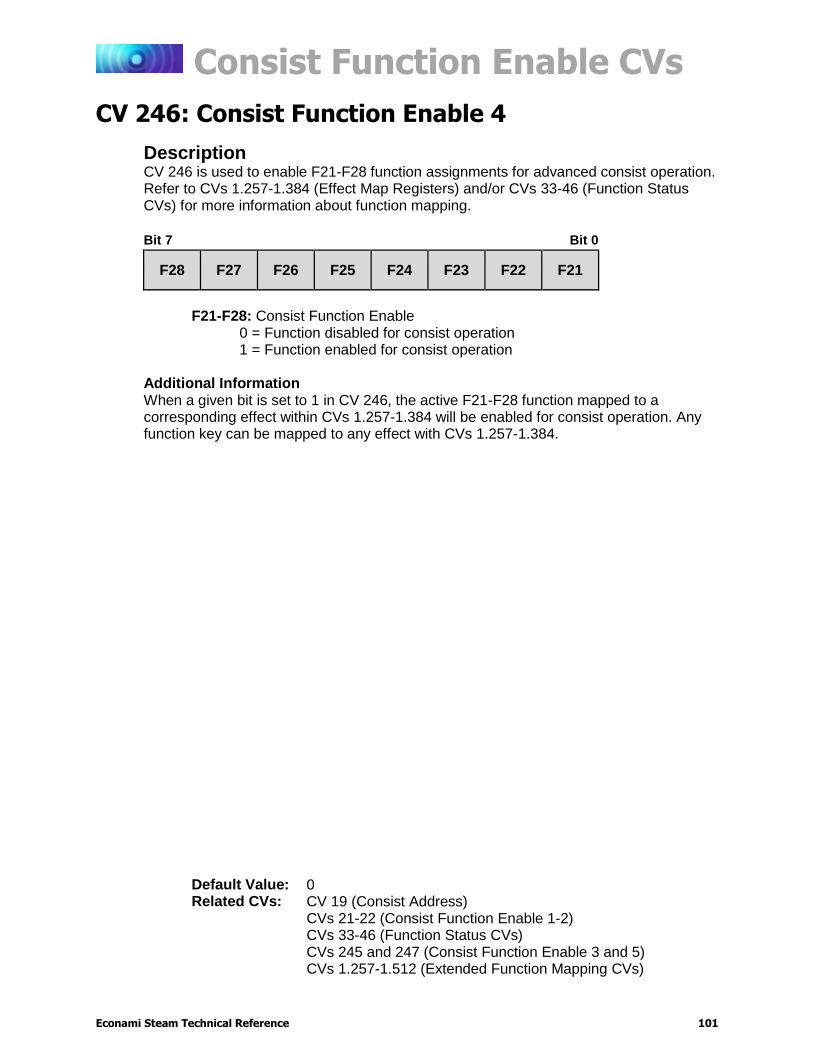
Consist Function Enable CVs
Econami Steam Technical Reference 101
CV 246: Consist Function Enable 4
Description CV 246 is used to enable F21-F28 function assignments for advanced consist operation. Refer to CVs 1.257-1.384 (Effect Map Registers) and/or CVs 33-46 (Function Status CVs) for more information about function mapping.
Bit 7 Bit 0
F28 F27 F26 F25 F24 F23 F22 F21
F21-F28: Consist Function Enable
0 = Function disabled for consist operation 1 = Function enabled for consist operation
Additional Information When a given bit is set to 1 in CV 246, the active F21-F28 function mapped to a corresponding effect within CVs 1.257-1.384 will be enabled for consist operation. Any function key can be mapped to any effect with CVs 1.257-1.384.
Default Value: 0 Related CVs: CV 19 (Consist Address)
CVs 21-22 (Consist Function Enable 1-2) CVs 33-46 (Function Status CVs) CVs 245 and 247 (Consist Function Enable 3 and 5) CVs 1.257-1.512 (Extended Function Mapping CVs)

Consist Function Enable CVs
Econami Steam Technical Reference 102
CV 247: Consist Function Enable 5
Description CV 247 is used in conjunction with CVs 1.385-1.512 (Effect Auxiliary Map Registers) to enable automatic effects and map an effect to the emergency stop button for advanced consist operation. The emergency stop button will bring the motor to a stop regardless of effect mapping.
Bit 7 Bit 0
0 0 0 ESTP REVS FWDS REVD FWDD
FWDD: Forward-Driving
0 = Effect is function controlled only 1 = Effect active when moving in forward direction
REVD: Reverse-Driving 0 = Effect is function controlled only 1 = Effect active when moving in reverse direction
FWDS: Forward-Standing 0 = Effect is function controlled only 1 = Effect active when stopped in forward direction
REVS: Reverse-Standing 0 = Effect is function controlled only 1 = Effect active when stopped in reverse direction
ESTP: Emergency Stop Button 0 = Emergency brake application sound effects enabled 1 = Effect mapped in CVs 1.385-1.512 (bit 4: ESTP) enabled
0: Reserved
Default Value: 0 Related CVs: CV 19 (Consist Address)
CVs 21-22 (Consist Function Enable 1-2) CVs 33-46 (Function Status CVs) CVs 245-246 (Consist Function Enable 3-4) CVs 1.257-1.512 (Extended Function Mapping CVs)
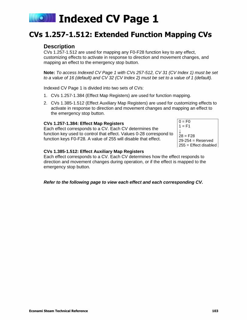
Indexed CV Page 1
Econami Steam Technical Reference 103
Indexed CV Page 1
CVs 1.257-1.512: Extended Function Mapping CVs
Description CVs 1.257-1.512 are used for mapping any F0-F28 function key to any effect, customizing effects to activate in response to direction and movement changes, and mapping an effect to the emergency stop button. Note: To access Indexed CV Page 1 with CVs 257-512, CV 31 (CV Index 1) must be set to a value of 16 (default) and CV 32 (CV Index 2) must be set to a value of 1 (default). Indexed CV Page 1 is divided into two sets of CVs:
1. CVs 1.257-1.384 (Effect Map Registers) are used for function mapping.
2. CVs 1.385-1.512 (Effect Auxiliary Map Registers) are used for customizing effects to activate in response to direction and movement changes and mapping an effect to the emergency stop button.
CVs 1.257-1.384: Effect Map Registers Each effect corresponds to a CV. Each CV determines the function key used to control that effect. Values 0-28 correspond to function keys F0-F28. A value of 255 will disable that effect.
CVs 1.385-1.512: Effect Auxiliary Map Registers Each effect corresponds to a CV. Each CV determines how the effect responds to direction and movement changes during operation, or if the effect is mapped to the emergency stop button. Refer to the following page to view each effect and each corresponding CV.
0 = F0 1 = F1
↓ 28 = F28 29-254 = Reserved 255 = Effect disabled
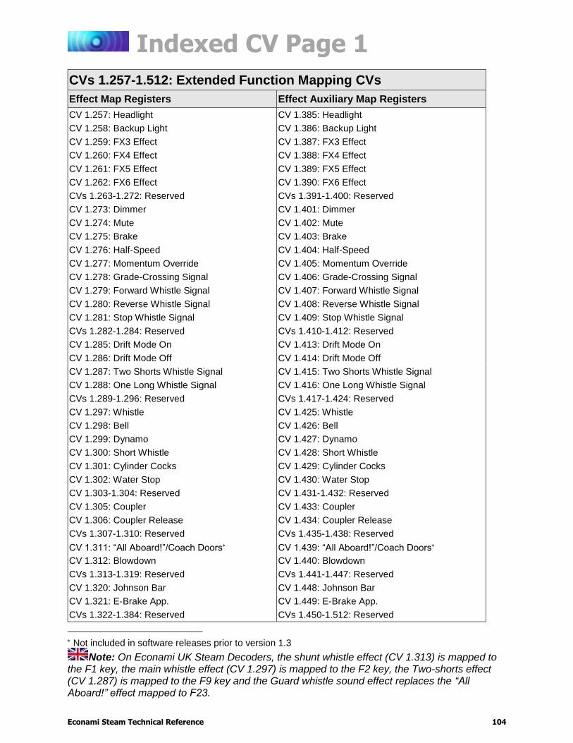
Indexed CV Page 1
Econami Steam Technical Reference 104
CVs 1.257-1.512: Extended Function Mapping CVs
Effect Map Registers Effect Auxiliary Map Registers
CV 1.257: Headlight CV 1.385: Headlight
CV 1.258: Backup Light CV 1.386: Backup Light
CV 1.259: FX3 Effect CV 1.387: FX3 Effect
CV 1.260: FX4 Effect CV 1.388: FX4 Effect
CV 1.261: FX5 Effect CV 1.389: FX5 Effect
CV 1.262: FX6 Effect CV 1.390: FX6 Effect
CVs 1.263-1.272: Reserved CVs 1.391-1.400: Reserved
CV 1.273: Dimmer CV 1.401: Dimmer
CV 1.274: Mute CV 1.402: Mute
CV 1.275: Brake CV 1.403: Brake
CV 1.276: Half-Speed CV 1.404: Half-Speed
CV 1.277: Momentum Override CV 1.405: Momentum Override
CV 1.278: Grade-Crossing Signal CV 1.406: Grade-Crossing Signal
CV 1.279: Forward Whistle Signal CV 1.407: Forward Whistle Signal
CV 1.280: Reverse Whistle Signal CV 1.408: Reverse Whistle Signal
CV 1.281: Stop Whistle Signal CV 1.409: Stop Whistle Signal
CVs 1.282-1.284: Reserved CVs 1.410-1.412: Reserved
CV 1.285: Drift Mode On CV 1.413: Drift Mode On
CV 1.286: Drift Mode Off CV 1.414: Drift Mode Off
CV 1.287: Two Shorts Whistle Signal CV 1.415: Two Shorts Whistle Signal
CV 1.288: One Long Whistle Signal CV 1.416: One Long Whistle Signal
CVs 1.289-1.296: Reserved CVs 1.417-1.424: Reserved
CV 1.297: Whistle CV 1.425: Whistle
CV 1.298: Bell CV 1.426: Bell
CV 1.299: Dynamo CV 1.427: Dynamo
CV 1.300: Short Whistle CV 1.428: Short Whistle
CV 1.301: Cylinder Cocks CV 1.429: Cylinder Cocks
CV 1.302: Water Stop CV 1.430: Water Stop
CV 1.303-1.304: Reserved CV 1.431-1.432: Reserved
CV 1.305: Coupler CV 1.433: Coupler
CV 1.306: Coupler Release CV 1.434: Coupler Release
CVs 1.307-1.310: Reserved CVs 1.435-1.438: Reserved
CV 1.311: “All Aboard!”/Coach Doors CV 1.439: “All Aboard!”/Coach Doors
CV 1.312: Blowdown CV 1.440: Blowdown
CVs 1.313-1.319: Reserved CVs 1.441-1.447: Reserved
CV 1.320: Johnson Bar CV 1.448: Johnson Bar
CV 1.321: E-Brake App. CV 1.449: E-Brake App.
CVs 1.322-1.384: Reserved CVs 1.450-1.512: Reserved
Not included in software releases prior to version 1.3
Note: On Econami UK Steam Decoders, the shunt whistle effect (CV 1.313) is mapped to the F1 key, the main whistle effect (CV 1.297) is mapped to the F2 key, the Two-shorts effect (CV 1.287) is mapped to the F9 key and the Guard whistle sound effect replaces the “All Aboard!” effect mapped to F23.
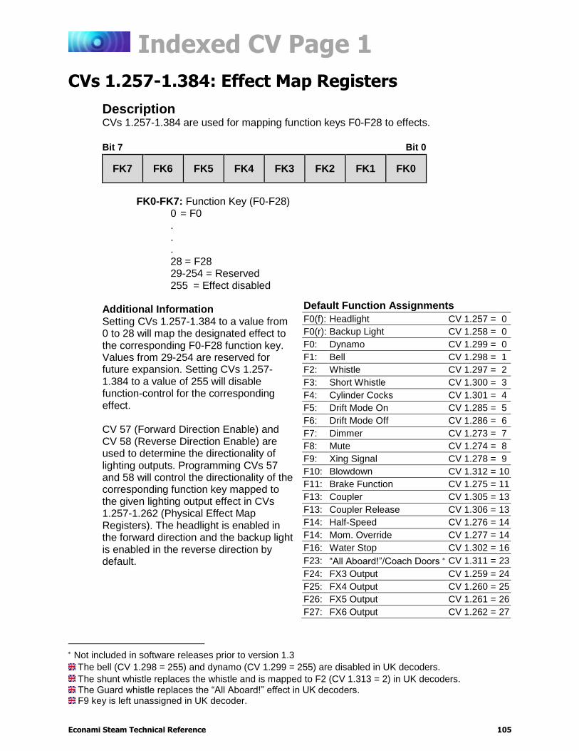
Indexed CV Page 1
Econami Steam Technical Reference 105
CVs 1.257-1.384: Effect Map Registers
Description CVs 1.257-1.384 are used for mapping function keys F0-F28 to effects.
Bit 7 Bit 0
FK7 FK6 FK5 FK4 FK3 FK2 FK1 FK0
FK0-FK7: Function Key (F0-F28)
0 = F0 . . .
28 = F28 29-254 = Reserved 255 = Effect disabled
Additional Information Setting CVs 1.257-1.384 to a value from 0 to 28 will map the designated effect to the corresponding F0-F28 function key. Values from 29-254 are reserved for future expansion. Setting CVs 1.257-1.384 to a value of 255 will disable function-control for the corresponding effect. CV 57 (Forward Direction Enable) and CV 58 (Reverse Direction Enable) are used to determine the directionality of lighting outputs. Programming CVs 57 and 58 will control the directionality of the corresponding function key mapped to the given lighting output effect in CVs 1.257-1.262 (Physical Effect Map Registers). The headlight is enabled in the forward direction and the backup light is enabled in the reverse direction by default.
Not included in software releases prior to version 1.3
The bell (CV 1.298 = 255) and dynamo (CV 1.299 = 255) are disabled in UK decoders.
The shunt whistle replaces the whistle and is mapped to F2 (CV 1.313 = 2) in UK decoders. The Guard whistle replaces the “All Aboard!” effect in UK decoders. F9 key is left unassigned in UK decoder.
Default Function Assignments
F0(f): Headlight CV 1.257 = 0
F0(r): Backup Light CV 1.258 = 0
F0: Dynamo CV 1.299 = 0
F1: Bell CV 1.298 = 1
F2: Whistle CV 1.297 = 2
F3: Short Whistle CV 1.300 = 3
F4: Cylinder Cocks CV 1.301 = 4
F5: Drift Mode On CV 1.285 = 5
F6: Drift Mode Off CV 1.286 = 6
F7: Dimmer CV 1.273 = 7
F8: Mute CV 1.274 = 8
F9: Xing Signal CV 1.278 = 9
F10: Blowdown CV 1.312 = 10
F11: Brake Function CV 1.275 = 11
F13: Coupler CV 1.305 = 13
F13: Coupler Release CV 1.306 = 13
F14: Half-Speed CV 1.276 = 14
F14: Mom. Override CV 1.277 = 14
F16: Water Stop CV 1.302 = 16
F23: “All Aboard!”/Coach Doors CV 1.311 = 23
F24: FX3 Output CV 1.259 = 24
F25: FX4 Output CV 1.260 = 25
F26: FX5 Output CV 1.261 = 26
F27: FX6 Output CV 1.262 = 27

Indexed CV Page 1
Econami Steam Technical Reference 106
CVs 1.385-1.512: Effect Auxiliary Map Registers
Description CVs 1.385-1.512 are used for configuring automatic effects and mapping an effect to the emergency stop button. A given effect can be configured to respond automatically to changes in direction (forward/reverse) and movement (driving/standing) during operation. The emergency stop button will perform the same utility irrespective of the effect mapped to it. CV 32 (CV Index 2) must be set to a value of 1 when accessing CVs 1.257-1.512.
Bit 7 Bit 0
0 0 0 ESTP REVS FWDS REVD FWDD
FWDD: Forward-Driving
0 = Effect activated by function key only 1 = Effect active when moving in forward direction
REVD: Reverse-Driving 0 = Effect activated by function key only 1 = Effect active when moving in reverse direction
FWDS: Forward-Standing 0 = Effect activated by function key only 1 = Effect active when stopped in forward direction
REVS: Reverse-Standing 0 = Effect activated by function key only 1 = Effect active when stopped in reverse direction
ESTP: Emergency Stop Button
0 = Emergency brake application sound effects (default) 1 = Effect mapped to emergency stop button
0: Reserved

Indexed CV Page 2
Econami Steam Technical Reference 107
Indexed CV Page 2
CVs 2.505-2.511: DDE Control CVs
Description CVs 2.503-2.512 are used to adjust parameters of the Dynamic Digital Exhaust (DDE) processor. Configuring DDE CVs allows the engine exhaust sound effects to be modified in response to motor load and/or speed during operation. Note: To access Indexed CV Page 2 with CVs 257-512, CV 31 (CV Index 1) must be set to a value of 16 (default) and CV 32 (CV Index 2) must be set to a value of 2.
CV 2.505: DDE Side Rod Clank Low Volume Limit
Description CV 2.505 is used to determine the maximum attenuation level of the side rod clank sound effect when the motor is operating at high speeds. The side rod clank low volume limit setting will be added to the corresponding mixer channel setting.
Bit 7 Bit 0
D7 D6 D5 D4 D3 D2 D1 D0
D0-D7: DDE Side Rod Clank Low Volume Limit
0 = 0dB 1 = -0.047dB . . .
255 = -12dB
Default Value: 255 Related CVs: CV 128 (Master Volume)
CVs 129-150 (Mixer Channel Volume Control) CVs 2.505-2.511 (DDE Control CVs)
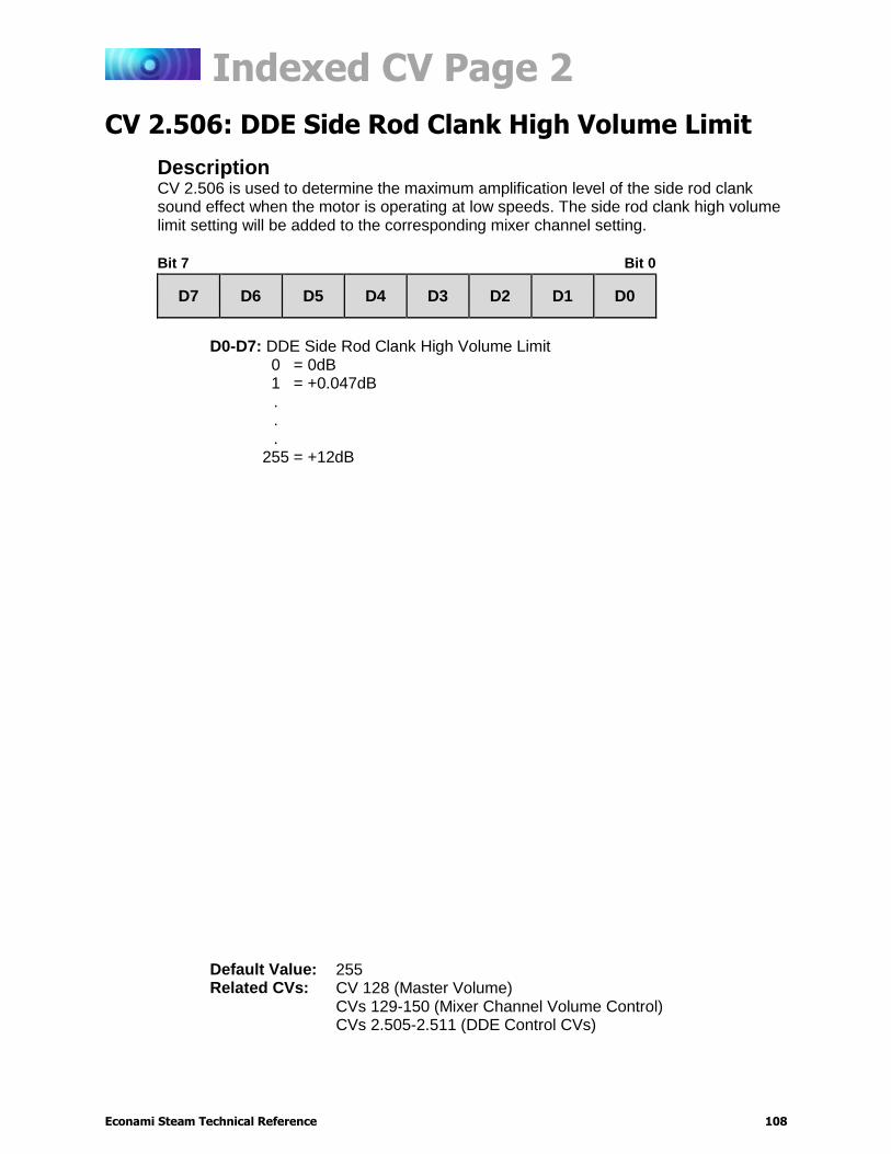
Indexed CV Page 2
Econami Steam Technical Reference 108
CV 2.506: DDE Side Rod Clank High Volume Limit
Description CV 2.506 is used to determine the maximum amplification level of the side rod clank sound effect when the motor is operating at low speeds. The side rod clank high volume limit setting will be added to the corresponding mixer channel setting.
Bit 7 Bit 0
D7 D6 D5 D4 D3 D2 D1 D0
D0-D7: DDE Side Rod Clank High Volume Limit
0 = 0dB 1 = +0.047dB . . .
255 = +12dB
Default Value: 255 Related CVs: CV 128 (Master Volume)
CVs 129-150 (Mixer Channel Volume Control) CVs 2.505-2.511 (DDE Control CVs)

Indexed CV Page 2
Econami Steam Technical Reference 109
CV 2.507: DDE Exhaust Low Volume Limit
Description CV 2.507 is used to determine the maximum attenuation level of the exhaust sound effect when the motor is operating at low speeds. The exhaust low volume limit setting will be added to the corresponding mixer channel setting.
Bit 7 Bit 0
D7 D6 D5 D4 D3 D2 D1 D0
D0-D7: DDE Exhaust Low Volume Limit
0 = 0dB 1 = -0.047dB . . .
255 = -12dB
Default Value: 255 Related CVs: CV 128 (Master Volume)
CVs 129-150 (Mixer Channel Volume Control) CVs 2.505-2.511 (DDE Control CVs)
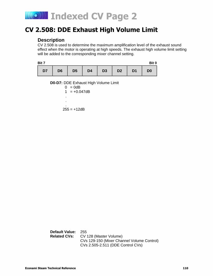
Indexed CV Page 2
Econami Steam Technical Reference 110
CV 2.508: DDE Exhaust High Volume Limit
Description CV 2.508 is used to determine the maximum amplification level of the exhaust sound effect when the motor is operating at high speeds. The exhaust high volume limit setting will be added to the corresponding mixer channel setting.
Bit 7 Bit 0
D7 D6 D5 D4 D3 D2 D1 D0
D0-D7: DDE Exhaust High Volume Limit
0 = 0dB 1 = +0.047dB . . .
255 = +12dB
Default Value: 255 Related CVs: CV 128 (Master Volume)
CVs 129-150 (Mixer Channel Volume Control) CVs 2.505-2.511 (DDE Control CVs)

Indexed CV Page 2
Econami Steam Technical Reference 111
CV 2.509: DDE Attack Time Constant
Description CV 2.509 is used to determine the DDE attack time constants, i.e., how quickly sound effects are modified in response to throttle changes. CV 2.509 determines the amount of time that elapses from the time the decoder receives a new throttle command to the time the DDE processor begins to reshape the audio signal. Longer response times (higher values) may help to ‘smooth out’ the DDE response.
Bit 7 Bit 0
D7 D6 D5 D4 D3 D2 D1 D0
D0-D7: DDE Attack Time Constant
0 = Shorter response time . . .
255 = Longer response time. Note: In previous Econami software releases 1.1 through 1.3, the Attack Time Constant range is inverted, meaning that lower values result in a longer response times and higher values result in shorter response times.
Default Value: 10 (Software versions 1.1 through 1.3) 216 (Software version 1.5)
Related CVs: CVs 2.505-2.511 (DDE Control CVs)
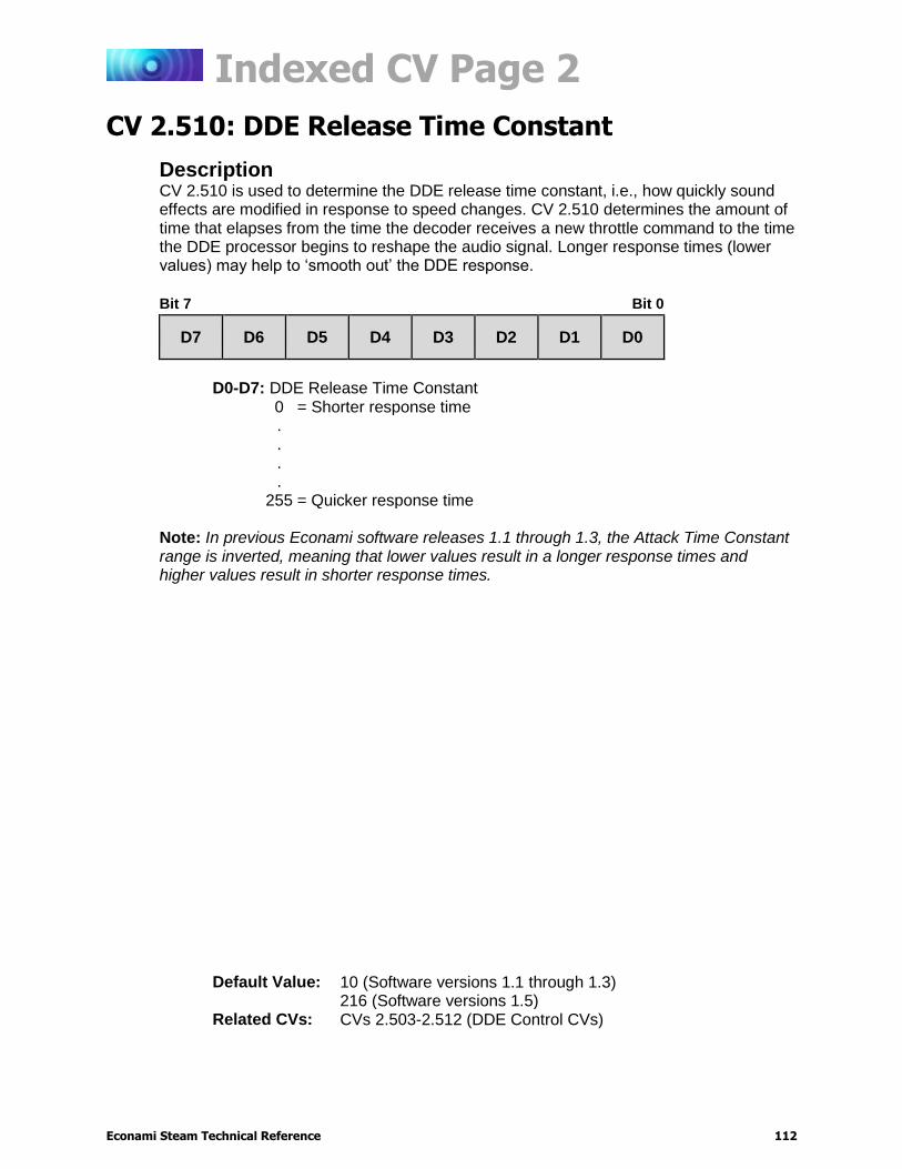
Indexed CV Page 2
Econami Steam Technical Reference 112
CV 2.510: DDE Release Time Constant
Description CV 2.510 is used to determine the DDE release time constant, i.e., how quickly sound effects are modified in response to speed changes. CV 2.510 determines the amount of time that elapses from the time the decoder receives a new throttle command to the time the DDE processor begins to reshape the audio signal. Longer response times (lower values) may help to ‘smooth out’ the DDE response.
Bit 7 Bit 0
D7 D6 D5 D4 D3 D2 D1 D0
D0-D7: DDE Release Time Constant
0 = Shorter response time . . . .
255 = Quicker response time Note: In previous Econami software releases 1.1 through 1.3, the Attack Time Constant range is inverted, meaning that lower values result in a longer response times and higher values result in shorter response times.
Default Value: 10 (Software versions 1.1 through 1.3) 216 (Software versions 1.5)
Related CVs: CVs 2.503-2.512 (DDE Control CVs)

Indexed CV Page 2
Econami Steam Technical Reference 113
CV 2.511: DDE Throttle Sensitivity
Description CV 2.511 is used to adjust the correlation between the throttle setting and speed-related sound effects. When the decoder has momentum programmed, this CV sets how much the load signal is affected by the model accelerating/decelerating.
Bit 7 Bit 0
D7 D6 D5 D4 D3 D2 D1 D0
D0-D7: DDE Throttle Sensitivity
0 = Disabled 1 = Minimum sensitivity . . .
255 = Maximum sensitivity Additional Information Setting CV 2.511 to 0 will disable DDE throttle sensing. Setting CV 2.511 to 255 indicates that the cadence and volume of speed-related sound effects will be most sensitive to the throttle setting.
Default Value: 10 Related CVs: CVs 2.505-2.511 (DDE Control CVs)


![Paragon 2 Steam Technical Reference Manual1.10].pdf · Paragon 2 Steam Technical Reference Manual . 2 INTRODUCTION Introduction The Paragon 2 sound unit is a multi-function DCC decoder](https://img.dokumen.tips/doc/110x75/5b5cb9487f8b9ad21d8cbc9e/paragon-2-steam-technical-reference-110pdf-paragon-2-steam-technical-reference.jpg)