Embed Size (px)
Citation preview

CARBONEX Sp. z o.o. ul. Budowlana 19
41-100 Siemianowice Śląskie tel/fax +48 32 2030819
www.carbonex.katowice.pl
====================================================================================================
DEVICE OF WIRELESS SHAFT COMMUNICATION
ECHO-S
TECHNICAL AND OPERATING MANUAL
No DTR-28S/2009
April 2013.

TABLE OF CONTENTS
1 Use and range of application. 2 Marking. 3 Certificates. 4 Terms of application. 5 Technical data. 6 Description. 7 Installation. 8 Maintenance. 9 Transport and storage. 10 List of spare parts. 11 Guarantee.
LIST OF DRAWINGS
28S. System ECHO-S – overall structure variant 1 28S.2 System ECHO-S – overall structure variant 2 28S.01 Cage device – outline drawing
28S.01.S.01 Cage device – block diagram
28S.01.S.02 Cage device – assembly diagram
28.01.05 Cage device – box type SAKN 28S.02 Headframe unit – outline drawing
28S.02.S.01 Headframe unit – block diagram
28S.02.S.02 Headframe unit – assembly diagram
28S.02.S.03 Headframe unit – input/output circuits
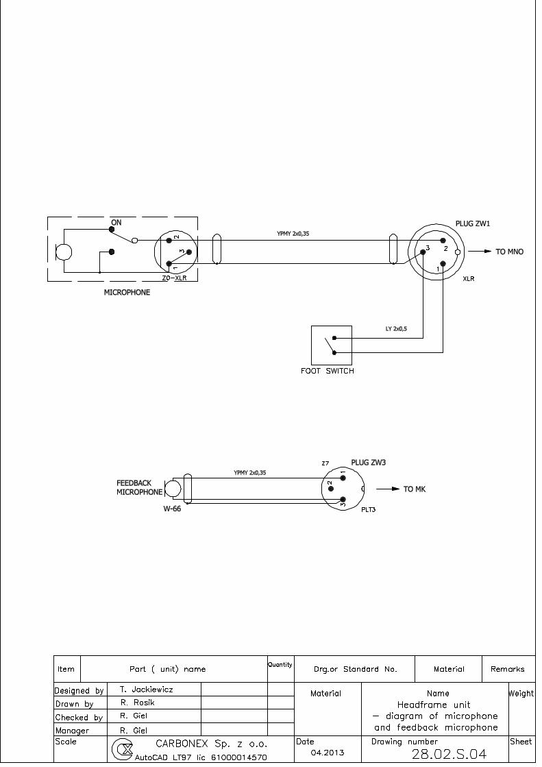
28.02.S04 Headframe unit – diagram of microphone and feedback microphone
28.03 Coupler type SK – outline drawing
28.03.M1 Coupler type SK – installation drawing variant 1
28.03.M2 Coupler type SK – installation drawing variant 2
28.04 Coupler type SS – outline drawing
28.04.M1 Coupler type SS – installation drawing variant 1
28.04.M2 Coupler type SS – installation drawing variant 2
28.05.S.01 Junction box type STK/E – interconnect wiring diagram
28.06.S.01 Junction box type SPSS – interconnect wiring diagram

Hazards identification
The cage unit is powered by 12VDC NiMH battery. It should be taken to consider that
in a fully charged battery during setting up might be done by accident shorting pins
which may cause battery leakage, overheat and in a consequence may cause injuries
(such as burns). The battery should be charged only by the original charger ŁAE-S3.
Used batteries should not be thrown away in the trash.
Headframe unit is supplied from 230 VAC network and should be connected to a wall
outlet with a protective pin (this applies to primary and reserve power supply). The
casing of headframe unit is made of sheet steel, so it should be grounded. Opening the
housing is allowed only after turning off power. The "!" sign on the input/output block
means that the inside can be dangerous voltage from the shaft system.
1. Use and range of application
Device of wireless shaft communication ECHO-S is designed to communicate between crew in conveyance (cage or skip) and hoist operator in mine shaft. The basic advantages of this system are following: - two-way half duplex audio communication, - sending remote control signals from cage to hoist, - receiving information signals from hoist to cage. The cage unit is made as intrinsically safe device group I, category M1. The device is intended to use in time of shaft inspection, person ride, emergency egress as well as maintenance in shaft. The principle of working of this device is utilization rope as carrier to move electromagnetic waves. Carrier is created by:
- headrope, tailrope and conveyances (in case of friction hoist), - guiderope and earth (in case of drum hoist), - additional rope and earth (in other cases).
Electric continuity of such loop is the main condition of correct work of device. Electromagnetic wave is generated to the loop and received from it by inductive couplers. In headframe there are fixed two inductive couplers (transmitter and receiver) in such way, that headrope crosses by their center. Over cage there are fixed another pair of couplers. Headframe unit sends signal by inductive coupler (transmitter) to rope and cage unit receive signals from rope by other inductive coupler (receiver). Communication from cage unit to headframe unit is performed in the same way by other pair of couplers. Only one device can work in one loop. The device has 4 frequency performances: A, B, C, D thanks to which, it is possible to use four devices in one shaft.

2. Marking
MARKING ABBREVIATED MARKING
Device of wireless shaft communication ECHO-S ECHO-S
The device consists of a headframe unit, cage unit and battery charger.
Cage unit consists of:
MARKING ABBREVIATED MARKING
Cage device type ECHO/AK-S frequency performance A,B,C,D ECHO/AK-S-A,B,C,D
Battery type BAKS-9 BAKS-9
Box type SAKN SAKN
Coupler type SK-32 (transmitter, frequency performance A) SK-32
Coupler type SK-64 (receiver, frequency performance A) SK-64
Coupler type SK-48 (transmitter, frequency performance B) SK-48
Coupler type SK-80 (receiver, frequency performance B) SK-80
Coupler type SK-80 (transmitter, frequency performance C) SK-80
Coupler type SK-80 (receiver, frequency performance C) SK-80
Coupler type SK-80 (transmitter, frequency performance D) SK-80
Coupler type SK-80 (receiver, frequency performance D) SK-80
Junction box type STK/E STK/E
Headframe unit consists of:
MARKING ABBREVIATED MARKING
Headframe device type ECHO/AS-S frequency performance A,B,C,D ECHO/AS-S-A,B,C,D
Microphone with foot switch microphone type MNO MNO
Loudspeaker Feedback microphone type MK MK
Coupler type SS-32 (receiver, frequency performance A) SS-32
Coupler type SS-64 (transmitter, frequency performance A) SS-64
Coupler type SS-48 (receiver, frequency performance B) SS-48
Coupler type SS-80 (transmitter, frequency performance B) SS-80
Coupler type SS-80 (receiver, frequency performance C) SS-80
Coupler type SS-80 (transmitter, frequency performance C) SS-80
Coupler type SS-80 (receiver, frequency performance D) SS-80
Coupler type SS-80 (transmitter, frequency performance D) SS-80
Junction box type SPSS SPSS
MARKING ABBREVIATED MARKING
Battery charger ŁAE-S3 ŁAE-S3

3. Certificates
Headrfame unit met requirement of the European Union directive no. 94/9/WE (ATEX) and other standards which are harmonized with them certificate no. KDB 09ATEX023X issued by the Notified Body no. 1453 Central Mining Institute. Experimental Mine „BARBARA” 43-190 Mikołów , ul. Podleska 72. The PCA (Polish Centre for Accreditation)
accreditation no. AC038.
As well as met requirement of electromagnetic compatibility in accordance with the European Union directive no. 89/336/EEC including the changes 91/263/EEC,92/31/EEC and 93/68/EEC and standards harmonized with it protocol no. LKE/043/2004 issued by the Laboratory of Electromagnetic Compatibility, Institute of Telecommunication and Acoustics Wroclaw Engineering College. The PCA (Polish Centre for Accreditation) accreditation no AB 167. 4. Terms of application
4.1. The shaft has to have tailrope, the conveyance must be suspended on at least two ropes or two guide ropes must exist.
4.2. There should be electrical connection between headrope and tailrope or between two guideropes.
4.3. Over the conveyance which we want to get communication should be mounted a pair of couplers, and second pair of couplers should be mounted in headframe.
4.4. In one shaft there may work only one cage unit in specific frequency performance, in the case of using two devices they have to have different frequency performance. The same applies to two cage units installed in one conveyance.
4.5. Couplers type SK (or SS in variant 2) can be connected only to cage unit ECHO/AK-S-x, connection may be made either directly or through box STK/E.
4.6. Battery type BAKS-9 can be charged only by battery charger type ŁAE-S3 made by CARBONEX.
4.7. Maintenance may be carried out only by authorized personnel. 4.8. It is forbidden to make any change in device and use the device in another way as
mentioned in this manual.

5. Technical data
5.1. Normal working conditions.
5.1.1. Cage unit
5.1.1.1. Temperature range -20ºC to + 40ºC
5.1.1.2. Humidity < 98%
5.1.2. Headframe unit
5.1.2.1. Temperature range 0ºC to + 40ºC
5.1.2.2. Humidity < 80%
5.2. General parameters
5.2.1. Type of work - audio signal semiduplex - remote control signals duplex
5.2.2. Type of modulation FM
5.2.3. Frequency performance:
- A (from cage unit to headframe unit) 32 kHz - A (from headframe unit to cage unit) 64 kHz - B (from cage unit to headframe unit) 48 kHz - B (from headframe unit to cage unit) 80 kHz - C (from cage unit to headframe unit) 112 kHz - C (from headframe unit to cage unit) 144 kHz - D (from cage unit to headframe unit) 128 kHz - D (from headframe unit to cage unit) 160 kHz
5.2.4. Method of sending signals serial
5.2.5. Delay of sending signals < 0,1 s
5.2.6. Range of work 1250 m
5.3. Cage unit
5.3.1. Power supply battery 12 V (10.5÷15 V)
5.3.2. Indication of low battery 11.5 V
5.3.3. Current consumption max. 400 mA
5.3.4. Output signal 14 Vpp
5.3.5. Receiver sensitivity 1 mV
5.3.6. Operating time without battery replacement 10 h 5.3.7. Marking I M1 Ex ia I Ma
5.3.8. Protection degree IP54
5.3.9. Dimensions 520 x 300 x 145 mm
5.3.10. Weight 15 kg
5.4. Headframe unit
5.4.1. Main and reserve power supply 230 VAC
5.4.2. Power consumption 50 VA
5.4.3. Output signal 14 Vpp
5.4.4. Receiver sensitivity 2 mV
5.4.5. Number, type and parameters of outputs 11 relays (DPDT 1A, 250VAC) 1 opto relay (2A, 200 VDC)
5.4.6. Number and type of input 14 NO contact
5.4.7. Dimensions 282 x 350 x 240 mm
5.4.8. Weight 10 kg

5.5. Coupler type SK
5.5.1. Nominal inductance SK-32 178 µH SK-48 80 µH SK-64 40 µH SK-80 40 µH 5.5.2. Protection degree IP54 5.5.3. Dimensions 265 x 220 x 90 mm 5.5.4. Weight 4,5 kg
5.6. Coupler type SS
5.6.1. Nominal inductance SK-32 178 µH SK-48 80 µH SK-64 40 µH SK-80 40 µH 5.6.2. Protection degree IP54 5.6.3. Dimensions 335 x 265 x 40 mm 5.6.4. Weight 4,5 kg
6. Description
Drawing no. 28S shows overall structure the communication system in arrangement with the headrope and tailrope. Drawing no. 28S.2 explains principle of work the communication system in arrangement with the guiderope. In headframe there are installed two inductive couplers in such a way that the rope passes through the center of couplers. One of them is transceiver and the second one is receiver. The second pair of couplers are fitted over conveyance. Transceiver coupler sends current signal, which flows through rope to the receiving coupler. The main condition of proper work of system is existence of a closed loop for current flow. This loop is formed by headrope, tailrope and conveyances. Other way of making such loop is by connecting two headropes. In case of existing guiderope loop may be done by making connection between two such ropes or by connecting to ground ends of guiderope. Blok diagram of cage device is shown in drawing no. 28S.01.S.01. Blok diagram of headframe device is shown in drawing no. 28S.02.S.01. Transmitters of both devices emit continuously carrier frequencies. There are two carrier frequencies at each system, which depend on devices performance. When the carrier frequency is received the device is switched to ready mode.
6.1. Audio communication is realized in an semiduplex way. In cage device broadcast is done after pressing the button "N/O", conveyance has priority. In headframe unit broadcast is done after pressing microphone foot switch.
6.2. Signal SJ is used to transmit the Code of Signal. After pressing button "SYGNAŁY JEDNOUDERZENIOWE" in cage device, output opto relay “SJ” is turned on for 200 milliseconds in headframe unit. In cage unit we should hear bell if feedback microphone would be fastened near to signal bell. Control block “BT” in headframe device turns on output opto relay “SJ” under following conditions:
• closed input no. 2 (person ride) or 3 (shaft inspection).

6.3. Signal alarm is send from cage device after pressing button "ALARM". It is possible to hear alarm bell in cage device, for this purpose should be closed input no. 4 in headframe unit. This input activates feedback microphone.
6.4. Signal blockade is done by switching the switch "BLOKADA" in cage unit into position “ZAŁ”. Next to the switch is red led confirming the activation of the lock (closed input no. 5 in headframe unit).
6.5. Automatic control is possible after switching the switch "ZDALNE URUCHOMIENIE" in cage unit into position "ZAŁ" and receiving confirmation of activation that state (closed input no. 8 in headframe unit).
Automatic control can only be enabled in shaft inspection mode (closed input no. 3 in headframe unit), using the following control buttons:
−raise, STOP –stop, −lower, V2 –middle speed, V3 –high speed.
Note:
The low speed “V1” should be automatically turned on when automatic control mode is selected.
Warning:
High speed V3 can only be available when the crew is in a safe place.
Identification of the location is realized by closing input US (man riding) in cage unit.
TABLE OF OUTPUTS OF HEADFRAME UNIT Relay Function Description
P1 Ready (GOT)
Relay is turned on, when cage unit and headframe unit are turned on, both are operational, and there is communication between them.
P2 Checking of Code of Signal
(KI)
Relay will be turned on for 6 seconds when:
- closed input no. 2 (person ride) or 3 (shaft inspection) and, - closed input no. 6 (machine in rest) and, - closed input no. 7 two or three times (raise, lower). Relay is released:
- after 6 seconds or, - after opening input no. 6 (machine in rest) or, - after closing input no. 7 one time (stop).
P3 Alarm (A)
In normal operation when headframe unit is in ready mode, relay is turned on. The relay will be turned off when: - closed input no. 2 (person ride) or 3 (shaft inspection) and, - button "ALARM" in cage device would be pressed or, - there will be a loss of communication between units.
P4 Blockade (B)
In normal operation when headframe unit is in ready mode, relay is turned on. The relay will be turned off when: - switch "BLOKADA" in cage unit would be set in position “ZAŁ” or, - there will be a loss of communication between units.

P5 Automatic control (ZU)
Relay will be turned on when:
- closed input no. 3 (shaft inspection) and, - switch "ZDALNE URUCHOMIENIE" in cage unit would be set in
position “ZAŁ”.
P6 Middle speed (V2)
Relay will be turned on when:
- closed input no. 3 (shaft inspection) and, - switch "ZDALNE URUCHOMIENIE" in cage unit would be set in
position “ZAŁ” and, - button "V2" in cage device would be pressed.
P7 High speed
(V3)
Relay will be turned on when:
- closed input no. 3 (shaft inspection) and, - switch "ZDALNE URUCHOMIENIE" in cage unit would be set in
position “ZAŁ” and, - button "V3" in cage device would be pressed and, - input US (pin 4, 7 in coupler socket) in cage unit is closed.
P8 Raise ()
Relay will be turned on when:
- closed input no. 3 (shaft inspection) and, - switch "ZDALNE URUCHOMIENIE" in cage unit would be set in
position “ZAŁ” and, - button "" in cage device would be pressed.
P9 Stop (STOP)
In normal operation when headframe unit is in ready mode, relay is turned on. The relay will be turned off when: - button "STOP" in cage device would be pressed or, - there will be a loss of communication between units.
P10 Lower ()
Relay will be turned on when:
- closed input no. 3 (shaft inspection) and, - switch "ZDALNE URUCHOMIENIE" in cage unit would be set in
position “ZAŁ” and, - button "" in cage device would be pressed.
P11 Man riding (US)
Relay will be turned on when:
- closed input US (man riding) in cage unit,
P12 Code of Signal (SJ)
Opto relay will be turned on for 200 milliseconds when: - closed input no. 2 (person ride) or 3 (shaft inspection) and, - button "SJ" in cage device would be pressed. Caution: when input no. 8 (automatic control) is closed, opto relay
is blocked.

6.6. Description of faceplate of cage unit
• "ZASILANIE"-switch on/off, when red led next to the switch lights means that the battery voltage is correct, when led flashes means discharging the battery.
• "ZDALNE URUCHOMIENIE"-automatic control switch, green led next to the switch lights when input no.8 in headframe unit is closed.
• "BLOKADA"-blockade switch, red led next to the switch lights when input no.5 in headframe unit is closed.
• "ALARM"-alarm button. • "SYGNALIZACJA JEDNOUDERZENIOWA"-button to transmit the Code of Signal,
yellow led “ZSJ” next to the button lights when input no.1 in headframe unit is closed, this led is used to indicate the Code of Signal mode.
• "V3"-high sped button, green led next to the button lights when input no.13 in headframe unit is closed.
• "V2"-medium sped button, green led next to the button lights when input no.12 in headframe unit is closed.
• "V1"-green led lights when input no.11 in headframe unit is closed. • "↑"-raise button, green led next to the button lights when input no.9 in headframe unit is
closed. • "STOP"-stop button. • "↓"-lower button, green led next to the button lights when input no.10 in headframe unit is
closed. • "N/O"-button for audio broadcasting. • "SN"-yellow led lights when the transmitter coupler is unserviceable. • "SO"-yellow led lights when the receiver coupler is unserviceable. • "FNN"-yellow led lights when there is a lack of carrier frequency of the transmitter. • "FNO"-yellow led lights when there is a lack of carrier frequency of the receiver. • "RSz"-green led indicates shaft inspection mode, lights when input no.3 in headframe unit
is closed. • "JO"-green led indicates person ride mode, lights when input no.2 in headframe unit is
closed. • "SPR"-green led indicates when the cage unit is ready for use. • "US"-yellow led indicates when input “man riding” (pin 4, 7 in coupler socket) in cage unit
is closed.
6.7. Description of faceplate of headframe unit
6.7.1. Power Block.
The leds indicates the presence of power supply.
6.7.2. Block BN
The led "SN" lights when the transmitter coupler is unserviceable. The led "KN" lights when there is a lack of carrier frequency of the transmitter. Led indicator indicates the level of transmitting wave.

6.7.3. Block BT
GOT Ready SJ Code of Signal A Alarm B Blockade ZU Automatic control ↑ Raise Stop Stop ↓ Lower V2 Medium speed V3 High speed US Man riding
6.7.4. Block BO
The led "SO" lights when the receiver coupler is unserviceable. The led "KO" lights when there is a lack of carrier frequency of the receiver. Led indicator indicates the level of receiving wave. Knob is used to adjust volume level.
6.7.5. Block BKI
KI Checking of Code of Signal
6.7.6. Block BSG1
ZSJ Code of Signal mode JO Person ride RSz Shaft inspection AL Alarm
BL Blockade MZ Machine in rest SJW Input of checking of Code of Signal
6.7.7. Block BSG2
ZU Automatic control ↑ Raise
↓ Lower
V1 Low speed
V2 Medium speed
V3 High speed
S1/S2 Control of pair of couplers
6.7.8. Block BSS
The led “S1” lights when pair of couplers S1 is turned on. The led “S2” lights when pair of couplers S2 is turned on
Couplers can be switched by the switch which is located on the front of the block or by input no. 14 in that case the switch should set in position "0". Open contact at input no. 14 switched pair of couplers S1 whereas closed input switched pair of couplers S2.

7. Installation
7.1. Unpacking
During unpacking, check the completeness of the set according to the proof of delivery. Check if the power switch on the cage unit was in off position during transport and storage. The switch in on position could cause discharging of battery.
7.2. Cage device
Cage device is shown in drawing no.28S.01. Housing is divided into two parts. At the bottom there are placed electronics board, buttons and switches, at the top battery socket. The walls of the housing are made of stainless steel sheet. In the bottom side of the housing there is a socket for connecting couplers and in the right side socket to charge battery without removing it out of housing. Access to battery and electronics board is possible after unscrewing proper cover. Device is designed for mounting on the wall of conveyance using 4 screws M8. If device is exposed to rain or water in shaft it is recommended to mount it in additional box SAKN.
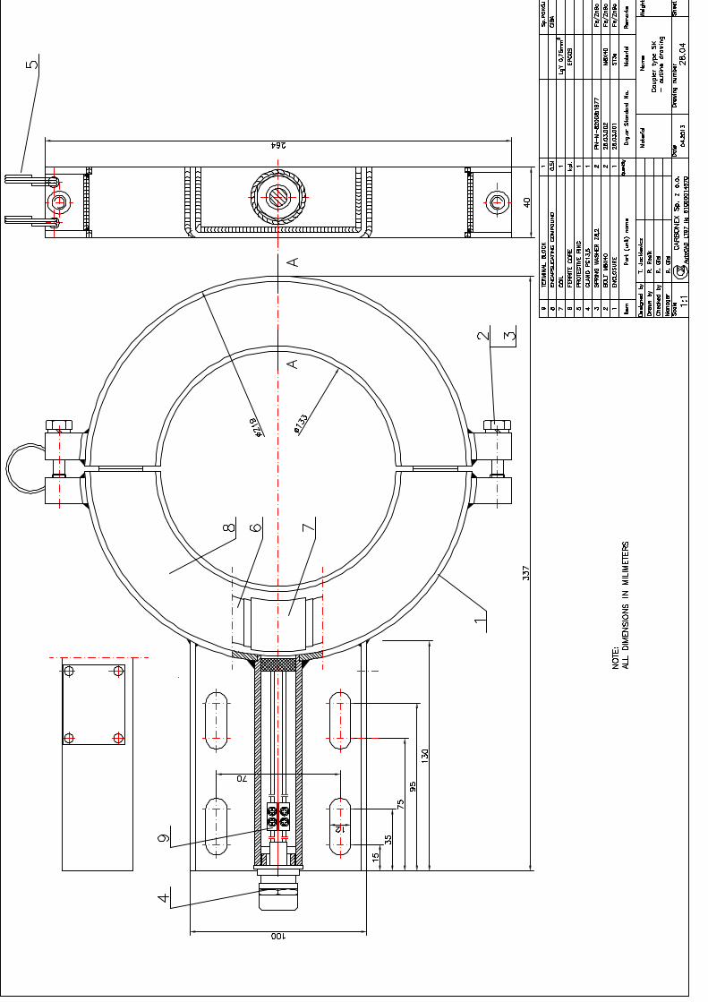
7.3. Coupler type SK
Coupler type SK is shown in drawing no.28.03. Coupler consists of two parts, to allow his assembly around rope. There is an ferromagnetic core with coil inside housing of device. Core and coil are encapsulated by chemical compound. There are two variant of installation of coupler. There is shown in drawings no.28.03.M1 and 28.03.M2.
7.4. Box type STK/E
Box type STK/E is shown in drawing no.28.05.S.01. It is designed to connect cables: PAK, PAKS and PAKD with couplers. Note:
The PAKD cable has incorporated connection between pins 4 and 7 for indicating
“man riding” mode.
7.5. Headframe unit
Headframe device is shown in drawing no.28S.02. Housing consist of three parts: power supply unit from the left side, main unit in the center and input/output circuit unit at the right side. Center unit consist of mainboard and subrack for 7 eurocards. Headframe unit is designed for mounting in the winding engine room using 4 screws M8. Method of connecting headframe unit is shown in drawing no.28S.02.S.02, 28S.02.S.03 and 28.S.02.S.04.
7.6. Coupler type SS
Coupler type SS is shown in drawing no.28.04. Coupler consists of two parts, to allow his assembly around rope. There is an ferromagnetic core with coil inside housing of device. Core and coil are encapsulated by chemical compound. There are two variant of installation of coupler. There is shown in drawings no.28.04.M1 and 28.04.M2. The couplers differ only way of fixing.
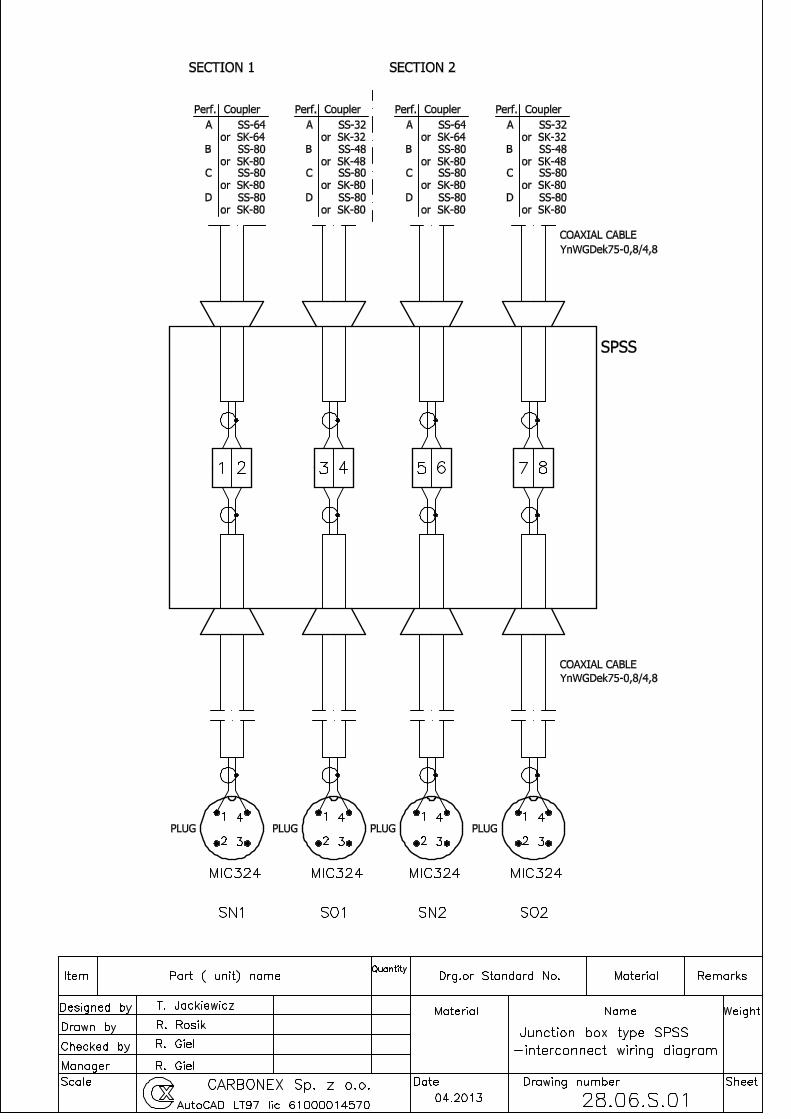
7.4. Box type SPSS
Box type SPSS is shown in drawing no.28.06.S.01. It is designed to connect coaxial cables with couplers if necessary.

8. Maintenance
Before using any cage device it is recommended to charge the battery, using a charger type ŁAE-S3 CARBONEX company production. Charging may take place only in room without any danger vapours. Battery, on which there are traces of leakage should be withdrawn by person of service and returned to the manufacturer. The battery may not have dents. In the headframe device power-up sequence is as follows: first "ZASILANIE PODSTAWOWE" (MAIN POWER) and second "ZASILANIE REZERWOWE" (RESERVE POWER). In other case there might be occur an arc on contacts of power supply switch relay. Cage device should not be at the same time, use the audio and control. After pressing simultaneously two control buttons only one of them will be send. The foot switch should be pushed only in time of audio transmission. Measurements of the installation should be performed at least once a year.
Inductance of coupler type SK should be measured in disconnected plug of cage unit. During the measurements the headframe unit must be turned off.
Type Value (Required) Comments Pin
SK-32 178 µH (150-240) µH Perf. (A) 3-6
SK-64 40 µH (30-60) µH Perf. (A) 2-5
SK-48 80 µH (65-120) µH Perf. (B) 3-6
SK-80 40 µH (30-60) µH Perf. (B,C,D) 2-5
Insulation resistance of coupler type SK should be measured in disconnected plug of cage unit. Measurement voltage 500 V. Measurement performed in safe zone between conveyance and Pin in accordance with the table.
Type Value Comments Pin
SK-32 > 100 kΩ Perf. (A) 3
SK-64 > 100 kΩ Perf. (A) 2
SK-48 > 100 kΩ Perf. (B) 3
SK-80 > 100 kΩ Perf. (B,C,D) 2
Inductance of coupler type SS should be measured in disconnected plug of cage unit. During the measurements the cage unit must be turned off.
Type Value (Required) Comments Pin
SS-32 178 µH (150-240) µH Perf. (A) 3-6
SS-64 40 µH (30-60) µH Perf. (A) 2-5
SS-48 80 µH (65-120) µH Perf. (B) 3-6
SS-80 40 µH (30-60) µH Perf. (B,C,D) 2-5
Insulation resistance of coupler type SS should be measured in disconnected plug of headframe unit. Measurement voltage 60 V. Measurement performed between ground and Pin in accordance with the table.
Type Value Comments Pin
SS-32 > 100 kΩ Perf. (A) 4
SS-64 > 100 kΩ Perf. (A) 4
SS-48 > 100 kΩ Perf. (B) 4
SS-80 > 100 kΩ Perf. (B) 4
9. Transport and storage
The device can be transported by any means of transport. During transport, equipment shall be protected against rain and strong mechanical shock. The temperature during transport should be in the range of -25ºC ÷ +60ºC. The device will be ready for use after keeping it in the room temperature for 6 hours. The device shall be stored in a closed room where the humidity should not exceed the permissible limit of 75% and the temperature ranging from 0°C to 60ºC. The room should be free of active vapours or chemical compounds. In case of storage longer than 14 days before installing cage device should be connected to the battery charger. 10. List of spare parts
10.1 Cage unit
10.1.1. Cage device type ECHO/AK-S-(A or B or C or D)
10.1.2. Battery type BAKS-9
10.1.3. Box type SAKN
10.1.4. Coupler type SK-32, 64, 48, 80
10.1.5. Plug type ZGT28KP7a
10.1.6. Socket ZGT28B7S
10.1.7. Box type STK/E
10.1.8. Cable PAK
10.1.9. Cable PAKD
10.1.10. Cable PAKS
10.1.11. Protection cover ZGT28W
10.2 Headframe unit
10.2.1. Headframe device type ECHO/AS-S-(A or B or C or D)
• Block BZ - power supply block
• Block BN - block of transmission
• Block BT - control block
• Block BO - block of receiving
• Block BKI - checking of Code of Signal block
• Block BSG1 - galvanic separation block • Block BSG2 - galvanic separation block
• Block BSS - control of couplers block
• Opto relay type W6212DDX-1
• Relay type Finder 48.52 (12VDC)
10.2.2. Microphone with foot switch microphone type MNO
10.2.3. Loudspeaker
10.2.4. Feedback microphone type MK
10.2.5. Coupler type SS-32, 64, 48, 80
10.2.6. Box type SPSS
10.2.7. Plug type MIC-324
10.2.8. Plug type MIC-323
10.2.9. Plug type MIC-322
10.2.10. Plug type XLR
It is allowed to replace these items. Any repair of components may only be performed by authorized employees of the CARBONEX company.

11. Guarantee
The manufacturer, CARBONEX Sp. z o.o. ul. Budowlana 19 41- 100 Siemianowice Śląskie, Poland
guarantees: 12.1. The highest quality and proper functioning of the device in accordance with the terms
and conditions given in this manual. 12.2. Guarantee period: 12 months from the date of purchase. 12.3. During guarantee period, all the repairs are carried out free of cost, provided that the
customer shall be responsible for any transportation cost. 12.4. Guarantee terms and conditions do not apply if the mechanical damages are caused by
improper use and operation of the device. 12.5. Sales and after sales service. After sales service and supply of spare parts on payment.
Any repair/damage shall be reported through phone/fax no. +48 32 203 08 19 or to service department of:
CARBONEX Sp. z o.o. ul. Budowlana 19 41- 100 Siemianowice Śląskie, Poland e-mail: [email protected] web: carbonex.katowice.pl