Embed Size (px)
Citation preview

©CFMRI Last modified 4/11/2014 1
Multi‐echoMulti‐slice(MEMS)HighPerformancefMRIatCFMRI
TableofContentsMulti‐echo Multi‐slice (MEMS) High Performance fMRI at CFMRI ........................................................................... 1
Introduction ........................................................................................................................................................... 2
MEMS Protocols .................................................................................................................................................... 4
Run MEMS protocol ............................................................................................................................................... 5
Set up and prepare ............................................................................................................................................ 5
Scan MEMS protocol ......................................................................................................................................... 5
End exam and transfer MEMS Data ................................................................................................................... 8
Reconstruct and pre‐process MEMS data ............................................................................................................. 8
Data Requirements ............................................................................................................................................ 9
Running the pipeline ......................................................................................................................................... 9
Error Logging ..................................................................................................................................................... 9
Output ............................................................................................................................................................. 10
Appendix I ............................................................................................................................................................ 11
Appendix II: MEMS Pipeline Output files ............................................................................................................ 12
Appendix III: MEICA (More information will be added as they become available) ............................................ 15

©CFMRI Last modified 4/11/2014 2
IntroductionA major need in the analysis of Blood Oxygen Level Dependent (BOLD) functional MRI (fMRI) data is the ability to
distinguish BOLD related signals from non‐BOLD related signals, such as those due to physiological fluctuations
or head motion. Previous studies 1 have shown that the amplitude of the BOLD signal variations has a linear
dependence on echo time (TE), whereas the amplitude of the non‐BOLD signal variations does not (Figure 1).
1 Peltier SJ, Noll DC, T2* dependence of low frequency functional connectivity, Neruoimage, 2002; 16(4)
TE1=15.5
TE2=36.7
TE3=57.9
Echo Time (TE)
% Signal Chan
ge
% Signal Chan
ge
Echo Time (TE)
Non‐BOLD signal (noise)
BOLD signal
AB
C
Figure 1. A: fMRI data acquired at 3 different TEs. B: noise signal
amplitude does not depend on TE. C: BOLD signal amplitude has a
linear dependence on TE. (Figure credit: Valur Olaffson)

©CFMRI Last modified 4/11/2014 3
Kundu et al 2 3 extended this observation
to Independent Component Analysis (ICA)
of multi‐echo fMRI data, where ICA
components that display TE dependencies
are considered BOLD signals; ICA
components that do not display TE
dependencies are considered noise and
thus removed from the fMRI data. This
fMRI denoising method, known as multi‐
echo ICA (ME‐ICA), has been shown to
robustly detect motion and other non‐
BOLD related signals, and to significantly
improve signal to noise ratio and
functional connectivity estimates (Figure
2).
A potential disadvantage of multi‐echo
fMRI is the time cost associated with
acquiring multiple echoes. However
various acceleration techniques are
available to speed up fMRI data
acquisition, such as the simultaneous
multi‐slice (SMS) technique where multiple ( N>1) slices are excited at a time providing a factor of N reduction
in scan time, and parallel imaging methods (such as GRAPPA or SENSE) that shorten the time required for the
readout of each echo. At the Center for fMRI (CFMRI) we provide an accelerated multi‐echo multi‐slice (MEMS)
protocol that is capable of acquiring full brain multi‐echo fMRI data with a TR of ~ 1sec. The use of multi‐echo
data with shorter TRs has been shown to improve the ability to detect functional networks.
Note that the MEMS protocol requires the use of the Nova Medical 32 channel head coil.
2 Kundu P et al, Differentiating BOLD and non‐BOLD signals in fMRI time series using multi‐echo EPI. Neuroimage, 2012;60(3) 3 Kundu P et al, Integrated strategy for improving functional connectivity mapping using multi‐echo fMRI, PNAS, 2013; 110(40)
Figure 2. Comparison of the default mode network maps
after applying standard denoising method (i.e. motion
correction) and MEICA method (Figure credit: Kundu et al;
2013).
Standard den
oising
MEICA den
oising
©CFMRI Last modified 4/11/2014 4
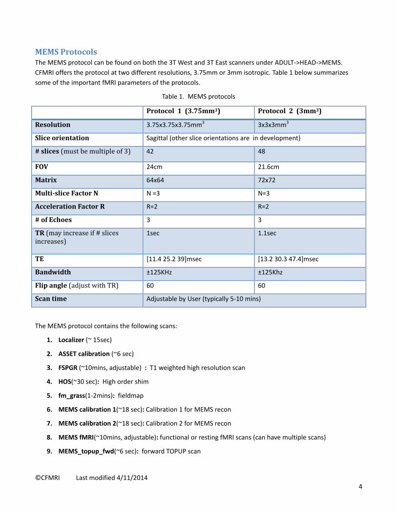
MEMSProtocolsThe MEMS protocol can be found on both the 3T West and 3T East scanners under ADULT‐>HEAD‐>MEMS.
CFMRI offers the protocol at two different resolutions, 3.75mm or 3mm isotropic. Table 1 below summarizes
some of the important fMRI parameters of the protocols.
Table 1. MEMS protocols
Protocol1 (3.75mm3) Protocol2(3mm3)
Resolution 3.75x3.75x3.75mm3 3x3x3mm3
Sliceorientation Sagittal (other slice orientations are in development)
#slices(mustbemultipleof3) 42 48
FOV 24cm 21.6cm
Matrix 64x64 72x72
Multi‐sliceFactorN N =3 N=3
AccelerationFactorR R=2 R=2
#ofEchoes 3 3
TR(mayincreaseif#slicesincreases)
1sec
1.1sec
TE [11.4 25.2 39]msec [13.2 30.3 47.4]msec
Bandwidth ±125KHz ±125Khz
Flipangle(adjustwithTR) 60 60
Scantime Adjustable by User (typically 5‐10 mins)
The MEMS protocol contains the following scans:
1. Localizer (~ 15sec)
2. ASSET calibration (~6 sec)
3. FSPGR (~10mins, adjustable) : T1 weighted high resolution scan
4. HOS(~30 sec): High order shim
5. fm_grass(1‐2mins): fieldmap
6. MEMS calibration 1(~18 sec): Calibration 1 for MEMS recon
7. MEMS calibration 2(~18 sec): Calibration 2 for MEMS recon
8. MEMS fMRI(~10mins, adjustable): functional or resting fMRI scans (can have multiple scans)
9. MEMS_topup_fwd(~6 sec): forward TOPUP scan

©CFMRI Last modified 4/11/2014 5
10. MEMS_topup_rvs(~6 sec): reverse TOPUP scan
The fm_grass scan and the calibration 1 and 2 scans are required for reconstructing the fMRI scan. If there is
more than one fMRI scan, the graphical prescriptions of all fMRI scans have to be matched exactly (use copyRx
on the scanner). If the prescription changes, a new set of the fm_grass, calibration 1 and 2, and the topup fwd
and rvs scans matching the new prescription will be required.
The topup_fwd and topup_rvs scan pair are used to measure a fieldmap which can be applied to the fMRI
images for correcting geometric distortions. They are typically scanned immediately before or after the fMRI
scans. In the case of a scan session containing several fMRI scans in a row where there is concern about subject
motion during the session, users may acquire one topup scan pair before the fMRI scans and another pair at the
end of the session. The first pair can be used for correcting the fMRI data before the motion occurs, and the
second pair for correcting the fMRI data after the motion.
RunMEMSprotocol
Setupandprepare1. Place the 32channel coil on the scanner table and plug it in. Make sure the coil is recognized by the
scanner by checking the information on the iROC monitor on top of the scanner.
2. Set up peripheral equipment such as the projector, screen, and stimulus laptop etc if needed.
3. Set up the subject on scanner patient table.
4. Setup physiological monitoring if needed.
5. On the console computer, click the downward arrow on the Tools icon. In the drop down menu, select
Command Window. In the command window type ‘RTctrl start’ to start realtime. Drag this window to
the lower right corner of the screen so it is easily accessible and not blocking the scan area of the screen.
(NOTE: this step must be done before Start Exam in step 6)
6. Register the subject and Start Exam.
ScanMEMSprotocol1. Localizer
Save Rx and Scan
2. Asset Cal
Setup, Prescribe Rx, Save Rx, and Scan
3. FSPGR T1
Setup, Prescribe Rx, Save Rx, and Scan.
IMPORTANT: While waiting for the FSPGR to finish, prescribe and save the “fm_grass” scan below the
HOS scan. This step MUST be done before running the next HOS scan.
4. HOS (high order shim)
Setup and Save Rx (no need to prescribe slices). Click OK in the popup window saying “Running high
order shim for clinical Protocol: fm_grass”. Then click Scan.

©CFMRI Last modified 4/11/2014 6
Once the scan finishes, an HOS window will appear. In the HOS window, adjust the size and location of
the ROIs to enclose the whole brain (see figure below);
Click Calculate Shim, then Done. Make a note of the current RMS and predicted RMS values reported in
the lower left of the window. The difference between the two values is indicative of HOS efficacy.
Run the HOS a second time by clicking Scan and choose Same Series in the popup window. Once the
HOS window appears, click Calculate Shim (do not modify the ROIs). Verify that the new current and
predicted RMS values are converging and consistent with the previously predicted value (See figure
below). If yes, click Done to finish.
The HOS scan can be repeated a third time if needed. We have typically seen RMS value convergence in
two iterations. In case the RMS value does not converge in three iterations, please click Quit to skip HOS.
Please alert the CFMRI staff of the HOS malfunction, or report the problem using the online web‐
schedule program at your earliest convenience.
5. fm_grass
Scan
fm_grass

©CFMRI Last modified 4/11/2014 7
6. mems cal 1(see NOTE below)
Copy Rx from fm_grass, save Rx, download, and scan.
7. mems cal 2 (see NOTE below)
Copy Rx from fm_grass, save Rx, download, and scan.
8. mems_rest_rvs (see NOTE below)
Copy Rx from fm_grass, save Rx, download, and scan.
9. mems_topup_fwd (see NOTE below)
Copy Rx from fm_grass , save Rx, download and scan.
10. mems_topup_rvs (see NOTE below)
Copy Rx from fm_grass, save Rx, download and scan.
NOTE:
Each of the mems scans (scan 6‐10) needs to be downloaded prior to the respective scan.
The download step ensures that RDS client is started to receive the acquired MRI data. If
the RDS client is not ON, no MRI data will be saved.
Below are some useful tools:
o Type ck in the command window to check if the RDS client is ON. This should be
checked after each download to make sure RDS client is ON before Scan.
o Type memslist in the command window to list the raw data files. Anytime during an
hcp scan, use memslist to check if data is being saved.
If an MEMS scan has to be stopped before it finishes, for example when subject activates
the emergency squeeze ball, please do the following:
o Type kk in the command window to kill the RDS client then press Stop Scan button.
After the emergency situation or errors are cleared, copy & paste the scan, download
and Scan.
o If the Stop Scan button is pressed before the RDS client is killed, a TPS reset must be
performed before the scan can continue. A TPS reset usually takes 2‐3 minutes. After
the TPS reset, copy & paste the scan, download and Scan.
Due to limitations with the RDS server software, after a mems scan finishes, the status of
the scan shows “Action Failed”. You can ignore this status. Additionally, as soon as the
next scan is downloaded, the previous mems scan is pushed downward in the scan list as
if it has not been scanned. Please pay attention to which scans have already been done
and which have not.
Appendix I lists all command‐line tools available for use with the MEMS protocols.

©CFMRI Last modified 4/11/2014 8
EndexamandtransferMEMSData On the computer console, click on End ‐> End Exam
In the command window, type RTctrl stop to stop realtime.
In the command window, type memscopy to transfer mems data (P files).
Usage: memscopy ‐s server –r raid# ‐d studyfolder login
example: memscopy –s fmrimems –r raid16 –d myhcpfolder mylogin
Transfer Dicom data using gecopy.
Usage: gecopy ‐s server ‐r raid# ‐d studyfolder login
example: gecopy –s fmrimems –r raid16 –d myhcpfolder mylogin
Transfer physio data using physiocopy as needed.
Usage: physiocopy ‐s server ‐d studyfolder starttime endtime login
example: physiocopy –s fmrimems –d myhcpfolder 14:00 15:00 mylogin
After data transfer completes, close all command windows and clean up the scanner suite.
Reconstructandpre‐processMEMSdataWe provide a Pipeline for reconstructing the MEMS data. The pipeline consists of four functional modules:
1. Data validation: checks if all required data files are present.
2. Data reconstruction: reconstructs the fMRI images.
3. Quality control: calculates temporal SNR and estimates T2* maps.
4. Pre‐processing (optional): performs motion correction, registration and distortion correction (see the
diagram below). Due to the use of in‐plane acceleration in the protocol, the in‐plane image distortions
are typically small, and so this step may be skipped at the discretion of the user.
Motion correction and
Registration to one of the
TOPUP pair that has the
same phase encoding
direction
( align_epi_anat.py)
fMRI data Echo 1
Apply distortion correction
( TOPUP)
fMRI data Echo 2 fMRI data Echo 3
Motion correction
(3dvolreg)
Apply the transformation
matrix from Echo 2
(3dAllineate)
Apply distortion correction
(TOPUP)
Motion correction
(3dvolreg)
Apply the transformation
matrix from Echo 2
(3dAllineate)
Apply distortion correction
(TOPUP)

©CFMRI Last modified 4/11/2014 9
5. post‐processing using MEICA (optional, see Appendix III) : Performs MEICA denoising.
SystemandDataRequirements Add the following path to your ~/matlab/startup.m file. Create the file if the file does not exist.
All data must be located in the same folder. Use unix command ls to check if all the data are present (see
example below). The data required include dicom files of the fmap scan and the T1 structural scan
(stored in exam/subject directory), and pfiles from the calibration scan 1 and 2 , one or more fMRI
scans, and two TOPUP scans
Runningthepipeline1. Login into your assigned server (either fmrimems.ucsd.edu or fmrimems2.ucsd.edu).
2. Change to the directory where the data are located.
3. Type at the Linux prompt: domems.py [‐topup] [‐meica]
Options:
‐topup: to apply EPI distortion correction
‐meica: to apply MultiEcho ICA (see Appendix III)
Your job will be queued. Type qstat to check queue status, or qdel followed by the job number to remove from
the queue.
ErrorLoggingA log file is automatically saved in the current data directory under the log folder. Automatic email notifications
will also be sent upon job success or failure to the email address registered with the server account (usually the
PI’s email address).
path(path,'/apps/matlabcode/spiralfmap2');
path(path,'/apps/matlabcode/domems');
path(path,'/apps/afni_matlab/matlab');
path(path,'/apps/matlabcode/fmritools');
fmrimems2.ucsd.edu:mems_data>> ls e207 (contains the s‐folders for the fmap_grass scan and the T1 structural scan) P12288_spep_mems_110829_0917.7 (Pfile for calibration scan 1) P12800_spep_mems_110829_0918.7 (Pfile for calibration scan2 ) P13312_spep_mems_110829_0918.7 (Pfile for fMRI scan) P13824_spep_mems_110829_0919.7 (Pfile for topup foward) P14336_spep_mems_110829_0920.7 (Pfile for topup reverse)

©CFMRI Last modified 4/11/2014 10
OutputAll output is saved under the processed folder. The pre‐processed fMRI data (motion and distortion corrected)
are: myhifipa0<study num>_e0<echo num>_afni_al.nii.gz
Example: myhifipa01_e01_afni_al.nii.gz
For a more complete description of the output files, please see Appendix II.
myhifipa01_e01_afni_al.nii.gz
myhifipa01_e02_afni_al.nii.gz
myhifipa01_e03_afni_al.nii.gz

©CFMRI Last modified 4/11/2014 11
AppendixI
Table 1: Summary of command‐line tools for running MEMS protocol
Command Usage Description
RTctrlstart RTctrl Start Start Realtime (Must be done before “Start Exam”)
RTctrlstop RTctrl Stop End Realtime (Must be done after “End Exam”)
ck ck Check if RDS client is ON
kk kk Kill all active RDS clients
memslist memslist List raw data files of the current MEMS scan session.
memscopy memscopy ‐s server ‐d studyfolder login Transfer MEMS raw data files to server.
gecopy gecopy ‐s server ‐r raid# ‐d studyfolder login
Transfer DICOM files to server.
physiocopy physiocopy ‐s server –d studyfolder starttime endtime login
(*starttime and endtime format: hh:mm)
Transfer physio files to fmrimems server.
cdtail
cd /export/home/sdc/RTafni/var/log tail –f <last log file name>
Check realtime status and log file

©CFMRI Last modified 4/11/2014 12
AppendixII:MEMSPipelineOutputfilesAll outputs are saved under “processed” folder. Below is a list of selected outputs that users may examine for
sanity check purpose or for trouble shooting when there are errors in the reconstruction process. Users should
contact CFMRI ([email protected]) for questions regarding these files.
bcaipi_<orientation>_<phase encoding dir>_mems0<study num>brik_e0<echo num>+orig.BRIK Example: bcaipi_sag_rev_mems01brik_e01+orig.BRIK
mems<study num>_e0<echo num>.nii.gz Example: mems01_e01.nii.gz
Reconstructed fMRI data (all 3 echoes) in BRIK and NIFTI format before motion correction and distortion correction. These images have visible distortions, but should be free of obvious artifacts, and have typical T2* BOLD contrast (the example below shows four brain slices).
topup_sag_fwdbrik+orig.BRIK and topup_sag_revbrik+orig.BRIK PhaseOne.nii.gz and PhaseTwo.nii.gz
Reconstructed images from the TOPUP scan pair in BRIK and NIFTI format. Verify that the distortions in these two datasets are opposite in direction to each other, and there are no obvious imaging artifacts.
coilmap_sag_rev_sess_fmapbrik+orig.BRIK
This is the reconstructed data from calibration 1 which will be used to estimate coil sensitivity profile. This scan is a spin echo, single band and single echo scan. The images should be free of artifacts, and have minimal signal dropout in the OFC area of the brain (see right).
anat.nii.gz
T1 Structure dataset in NIFTI format (if provided)
mems01_e01.nii.gz
mems01_e03.nii.gz
mems01_e02.nii.gz
PhaseOne.nii.gz
PhaseTwo.nii.gz

©CFMRI Last modified 4/11/2014 13
bcaipi_<orientation>_<phase encoding dir>_mems0<study num>brik _T2s.jpg bcaipi_<orientation>_<phase encoding dir>_mems0<study num>brik _T2s_hist.jpg bcaipi_<orientation>_<phase encoding dir>_mems0<study num>brik _e01_tSNR.jpg bcaipi_<orientation>_<phase encoding dir>_mems0<study num>brik _e01_tSNR_hist.jpg bcaipi_<orientation>_<phase encoding dir>_mems0<study num>brik _e02_tSNR.jpg bcaipi_<orientation>_<phase encoding dir>_mems0<study num>brik _e02_tSNR_hist.jpg bcaipi_<orientation>_<phase encoding dir>_mems0<study num>brik _e03_tSNR.jpg bcaipi_<orientation>_<phase encoding dir>_mems0<study num>brik _e03_tSNR_hist.jpg
The T2* and tSNR maps generated for Quality Assurance (see examples below).

©CFMRI Last modified 4/11/2014 14
b02b0.cnf acqparams5r.txt BothPhases.topup_log Coefficents_fieldcoef.nii.gz Coefficents_movpar.txt TopupField.nii.gz Magnitudes.nii.gz
Topup configuration and intermediate files (for more information about the TOPUP distortion correction method please refer to the FSL web site).
mems0<study num>_e0<echo num>_vr.nii.gz mems0<study num>_e0<echo num>_afni_al.nii.gz mems0<study num>_e0<echo num>.nii.gz_vr_motion.1D mems0<study num>_e0<echo num>.nii.gz_al_mat.aff12.1D mems0<study num>_e0<echo num>.nii.gz_al_reg_mat.aff12.1D
Motion corrected and reregistered fmri data (all three echoes). The 1D files are the motion parameters and transformation matrices. Please see Reconstruct and pre‐process MEMS data section for information on registration steps.
script_<timestamp>.sh Example: script_2013‐10‐24‐18:59:34.sh
Pre‐processing script containing motion and distortion correction steps. User can look up the pre‐processing steps carried out to the fMRI dataset.

©CFMRI Last modified 4/11/2014 15
AppendixIII:MEICA(Moreinformationwillbeaddedinafutureversionofthismanual)
The Pipeline also supports the MEICA denoising method. To invoke MEICA denoising automatically after the
pipeline finishes reconstructing data, use the ‐‐meica option when calling domems.py. For example
domems.py ‐‐meica
The script requires the following python path to be included in your .cshrc file:
set path=( $path . ~/bin /usr/local/bin /apps/Enthought/Canopy_64bit/User/bin )


![FIL Event--related related fMRIfMRI Event-related fMRI · • Sampling at [0,4,8,12…] post-stimulus may miss peak signal • Typical TR for 48 slice EPI at 3mm spacing is ~ 4s •](https://img.dokumen.tips/doc/110x75/5f08f3387e708231d4248297/fil-event-related-related-fmrifmri-event-related-fmri-a-sampling-at-04812.jpg)