Embed Size (px)
Citation preview

+
風力発電が電力系統に提供できる アンシラリーサービス
関西大学 システム理工学部 准教授 安田 陽
第21回CEEシンポジウム
再生可能エネルギー 時代の電力需給の 新たな調整資源
を考える
2015年5月11日 @東京大学
生産技術研究所 コンベンションホール
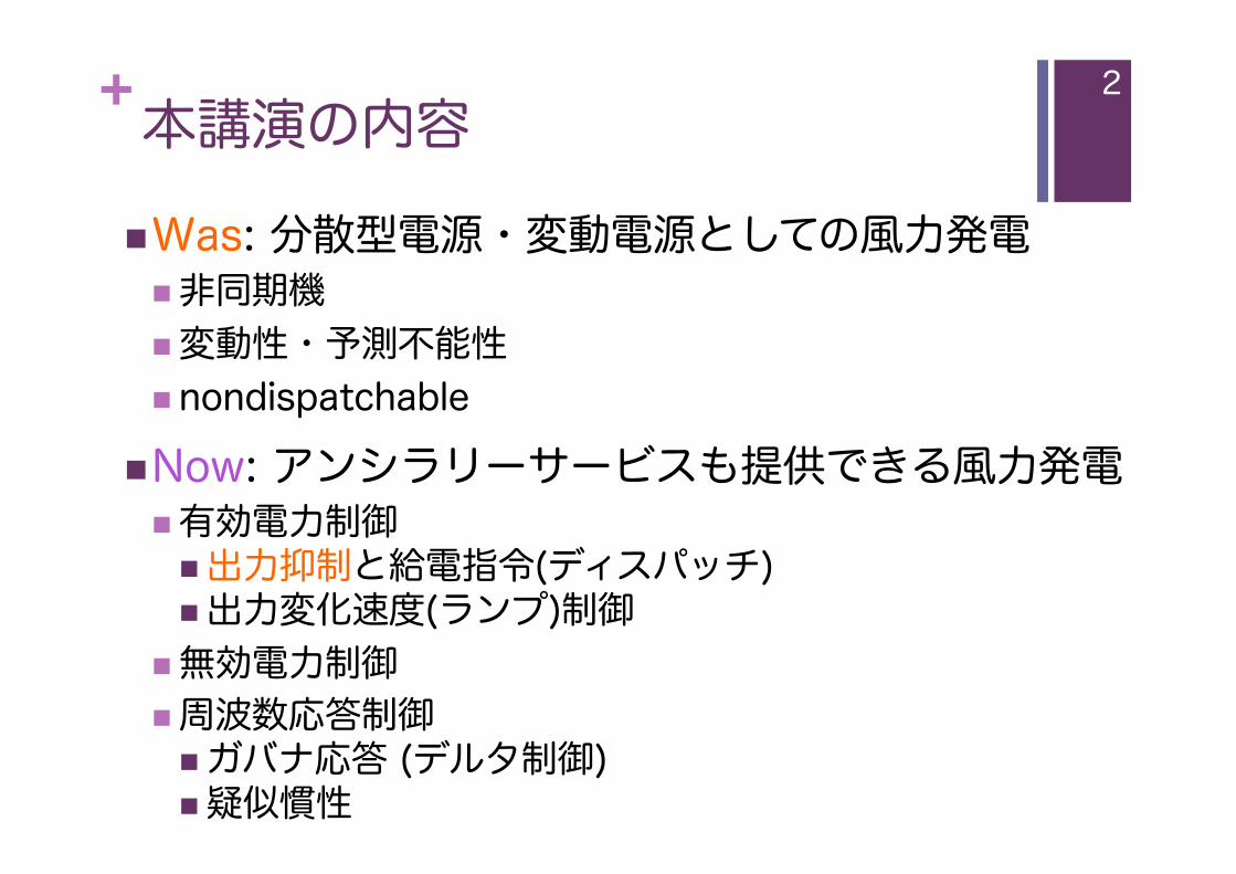
+本講演の内容 ! Was: 分散型電源・変動電源としての風力発電
! 非同期機 ! 変動性・予測不能性 ! nondispatchable
! Now: アンシラリーサービスも提供できる風力発電 ! 有効電力制御
! 出力抑制と給電指令(ディスパッチ) ! 出力変化速度(ランプ)制御
! 無効電力制御 ! 周波数応答制御
! ガバナ応答 (デルタ制御) ! 疑似慣性
2

+本日の参考文献 (1/2)
! Ackermann編著: 「風力発電導入のための電力系統工学」, オーム社 (2013) ! 第12章 グリッドコードの性能検証と認証 Markus Fischer et al. (Enercon)
! 第13章 風力発電の電気設計 N. Miller et al. (GE Energy)
! 第40章 大規模ウィンドファームの 集合化モデルと短時間電圧安定性 V. Ackhmatov and B. Andersen (Siemens Wind)
! など
3

+本日の主な参考文献 (2/2)
! Siemens: White Paper “Siemens Wind Turbines – Wind Power Supervisor (WPS) /Park Pilot”, 2010
! TWENTIES Project: Final Report, 2013 ! TWENTIES Project: DEMO 1 (WP 9: System
Services Provided by Wind Farms), 2013
! A. Hansen and M. Altin: “Impact of advanced wind power ancillary services on power system”, DTU Wind Energy Report 2015
TWENTIES project Final report October 2013
SWP EN White Paper, WPS/Park PilotDocument ID: E R WP EN-60-0000-1304-02
Henrik Stiesdal / 2010.04.25Conveyed confidentially as trade secret
Siemens Wind Power A/S © All Rights Reserved 2010
1 / 19Siemens Wind Turbines, EN White Paper, Park Pilot, 2010.04.25.doc
Siemens Wind Turbines Wind Power Supervisor (WPS) /Park Pilot White Paper Henrik Stiesdal
4
DTU
Vin
dene
rgi
E R
appo
rt 2
015
Impact of advanced wind power ancillary services on power system
Anca D. Hansen and Müfit Altin
DTU Wind Energy E-0081
January 2015

+
風力発電の 系統運用への貢献 (有効電力制御)
出力抑制 需給バランス制御 ランプ制御 デルタ制御
6

+風力発電所の系統運用への貢献
! 出力抑制 ! 需給バランス制御 (出典) IEA Wind Task25:「風力発電大量導入時の電力系統の設計と運用」, 日本電機工業会 (2013)
7
2. Power system impacts of wind power
33
• delta control where the output of the wind power plant with a delta amount so this amount can be used as spinning reserve
• rate limitation where the output of the wind power plant is not allowed to increase more than a specified amount per minute
• droop control
• system protection by output reduction.
Absolute Power Limitation Balance Control Power Rate Limitation
Delta Control
Power Power Power Power
time time time time
Possible
Actual
Possible Possible Possible
Actual Actual
Actual
Fig 13. Outline of the active power control functions. The plots show the possible power and the actual achieved power with the different control functions active.
The four first types of regulation are illustrated in Fig 13. Results from the Horns Rev wind power plant executing several types of regulation commanded are shown in Fig 14 (Kristoffersen, 2005). It shows that the wind power plant is quite capable of performing fast regulation of the output.
出力
時間
実際の出力
利用可能電力

+風力発電所の系統運用への貢献
! ランプ制御 ! デルタ制御
8
(出典) IEA Wind Task25:「風力発電大量導入時の電力系統の設計と運用」, 日本電機工業会 (2013)
2. Power system impacts of wind power
33
• delta control where the output of the wind power plant with a delta amount so this amount can be used as spinning reserve
• rate limitation where the output of the wind power plant is not allowed to increase more than a specified amount per minute
• droop control
• system protection by output reduction.
Absolute Power Limitation Balance Control Power Rate Limitation
Delta Control
Power Power Power Power
time time time time
Possible
Actual
Possible Possible Possible
Actual Actual
Actual
Fig 13. Outline of the active power control functions. The plots show the possible power and the actual achieved power with the different control functions active.
The four first types of regulation are illustrated in Fig 13. Results from the Horns Rev wind power plant executing several types of regulation commanded are shown in Fig 14 (Kristoffersen, 2005). It shows that the wind power plant is quite capable of performing fast regulation of the output.
出力
時間
実際の出力
利用可能電力
出力
時間
実際の出力
利用可能電力

+出力抑制の実施例 (アイルランド)
0"
5"
10"
15"
20"
25"
30"
35"
40"
45"
0"
1000"
2000"
3000"
4000"
5000"
6000"
%"
MW"
Hour"
Load"15-Jan-11" Wind"15-Jan-11" %"Wind"Penetration"15-Jan-11"
200 MW 出力抑制 (02:45~06:30)
(出典) M. O’Malley: Wind integration workshop in Tokyo (2012)�
9

+出力抑制の実施例 (米国テキサス)
(出典) http://www.eia.gov/todayinenergy/detail.cfm?id=16831#tabs_SpotPriceSlider-2�
10

+風力発電所のランプ制御試験 (Siemens Wind)
SWP EN White Paper, WPS/Park PilotDocument ID: E R WP EN-60-0000-1304-02
Henrik Stiesdal / 2010.04.25Conveyed confidentially as trade secret
Siemens Wind Power A/S © All Rights Reserved 2010
8 / 19Siemens Wind Turbines, EN White Paper, Park Pilot, 2010.04.25.doc
Fig. 3.1 MW ramp control A well defined slope of the actual power illustrates the ability to control the ramp very accurately from in this case 120 MW to about 0 MW. A separate parameter controls the ramp-up rate of change, and in addition to applying the ramp func-tion during parameter changes it can also be set up to apply during start-up of the wind power plant. This is particularly important after a high wind shut-down or a power restoration during high wind con-ditions. In both such conditions the turbines will be resuming production in a staggered fashion based on individual start delay timers or as dictated by the terrain. To further control the power rate of change the start-up ramp rate function is available. A special version of ramp rate control can be activated to reduce the production variation during nor-mal production (Variation Control). This function will only control the rate of MW increase as the wind speed picks up or new turbines are released for production. It will not have any impact on the down-wards rate of change.
(��) Siemens: White Paper , 2010
11

+風力発電所の周波数応答試験 (Siemens Wind)
(��) Siemens: White Paper , 2010
SWP EN White Paper, WPS/Park PilotDocument ID: E R WP EN-60-0000-1304-02
Henrik Stiesdal / 2010.04.25Conveyed confidentially as trade secret
Siemens Wind Power A/S © All Rights Reserved 2010
10 / 19Siemens Wind Turbines, EN White Paper, Park Pilot, 2010.04.25.doc
A sensitive mode frequency response configuration is an available option where the wind power plant is set up to respond to over- and under-frequency. To utilize this operational mode, the ability to in-crease the power production during low frequency events is essential and the power must be main-tained at a level below the available power, e.g. by a delta control. A typical frequency deadband set-ting for the sensitive mode is +/- 0.015 Hz for 50 Hz systems (0.0167 Hz for 60 Hz systems). The re-sponse can be adjusted by adjusting the slope of a droop characteristic.
Fig. 4.1 Proportional response to frequency injection signal During the test plotted in Fig. 4.1, the wind power plant was operating with a reduced output (with a spinning reserve), making it possible to increase the power output in response to the injected and measured frequency signals.
Fig. 4.2 Proportional response to injection above nominal frequency
Siemens Frequency Response
出力変化速度 (ランプレート) < 10%/min
12

+デルタ制御試験 (デンマーク)
! 上方および下方予備力を提供可能 ! デンマークでは洋上風力発電所 (Horns RevおよびNysted) に実装済み
Delta control – Danish grid code
• Delta control provides fixed reserve • Reserve can be utilised in
• Delta control already implemented in Horns Rev and Nysted
Reserve can be utilised in frequency control (droop and deadband)
1 Power
0 6
0.7
0.8
0.9
1
.]
PavailPdel
P
0.3
0.4
0.5
0.6
Pow
er [p
u
Pref,wf
PavailPdelPdel
0
0.1
0.2
0 100 200 300 400 500 600 Frequencfsy fs+fdy fd+
Risø DTU, Technical University of DenmarkRisø DTU, Technical University of Denmark 16 April 2009WES seminar10
Time [s]
(出典) P. Sørensen: Frequency control in power systems with large scale wind power, Risø DTU (2009)�
13
周波数調定率制御

+デンマークのグリッドコード におけるデルタ制御の規定 Danish grid code for wind turbines
Risø DTU, Technical University of DenmarkRisø DTU, Technical University of Denmark 16 April 2009WES seminar9
(出典) P. Sørensen: Frequency control in power systems with large scale wind power, Risø DTU (2009)�
14

+
風力発電所の電圧制御 (無効電力制御)
15

+風力発電所の電圧制御試験 (Siemens Wind)
(��) Siemens: White Paper , 2010
SWP EN White Paper, WPS/Park PilotDocument ID: E R WP EN-60-0000-1304-02
Henrik Stiesdal / 2010.04.25Conveyed confidentially as trade secret
Siemens Wind Power A/S © All Rights Reserved 2010
11 / 19Siemens Wind Turbines, EN White Paper, Park Pilot, 2010.04.25.doc
Note that the turbine attains minimum power almost coincidentally with the maximum frequency. Obvi-ously, the turbines are much faster than steam or gas turbines, which are usually constrained by a ramp rate of 10% per minute or less. With their fast regulation, the wind turbines are able to contribute more effectively to maintaining the grid frequency. Trigger limits and gain values can be set up based on a large set of configuration parameters and the frequency response can be activated and deactivated during operation without stopping the wind power plant.
5. Voltage Control
Being able to contribute to a stable voltage at the wind turbine level introduces a significant amount of flexibility in grid operation and design. The wind power plant can be configured to play an integral role in maintaining the grid voltage within required levels. The FSFC wind turbine, together with the High Performance Park Pilot (HPPP), utilizes two levels of regulation to achieve reliable voltage regulation. The first voltage regulation loop is located locally in the wind turbine controller. This is a fast acting regulator following the reference transmitted from the central voltage controller in the HPPP. At a slower rate, the central voltage controller broadcasts new references to the turbines every 150 ms. The reference value is calculated based on the number of wind turbines available, the central voltage reference, the measured voltage, and the reactive power exchange at the wind farm central measurement and control point. Operating the turbines with a combination of central voltage control, local voltage control and a low-voltage ride-through function at the local level will optimize response to grid voltage sags or swells. At the same time, the mechanical structure of the turbine is decoupled from the grid so that large devia-tions on the grid do not directly transfer to high torques to the gearbox, bearings or blades.
Fig. 5.1 Voltage reference step test (1% step up/down followed by 2% step up/down)
16

+風力発電所の電圧制御試験 (Siemens Wind)
SWP EN White Paper, WPS/Park PilotDocument ID: E R WP EN-60-0000-1304-02
Henrik Stiesdal / 2010.04.25Conveyed confidentially as trade secret
Siemens Wind Power A/S © All Rights Reserved 2010
12 / 19Siemens Wind Turbines, EN White Paper, Park Pilot, 2010.04.25.doc
As the voltage changes at the central point of control, the voltage will change at the turbine level and the fast voltage control loop will respond, increasing or reducing the voltage as directed. The central voltage controller fine-tunes the response, including the slope defined by the reactive droop setting, by adjusting the references transmitted to the turbines. The control is tuned to optimize reaction time with minimal overshoot. For installations where the Siemens wind power plant operates in conjunction with a separate Flexible AC Transmission System (FACTS) device like Static Var Compensator (SVC) or static synchronous compensator (STATCOM), a set of parameters or tags can be exported via a communication interface. The interface makes it possible to coordinate the FACTS device control in order to get a stable opera-tion, so that the two systems work in harmony. Similarly, if a Siemens wind power plant is installed next to another voltage control system, it is possi-ble to define a voltage droop control to prevent oscillations between two neighboring voltage control systems. The other system can be another wind power plant, a synchronous generator, or any other type of voltage control device.
Fig. 5.2 Central voltage control with active slope (droop control) In the instance above, the voltage reference was set to 34.5 kV (no reactive power exchange with the grid at nominal voltage). As the voltage increases, the amount of reactive power absorbed by the wind power plant increases. The FSFC remains in voltage control mode to optimize response to sags or swells in the grid voltage. While operating in voltage control, reactive power is provided within the wind farm capability. However, to avoid sudden spikes in the reactive power flow during voltage control when the wind speed is insuf-ficient for active power production is it in some cases necessary to add user constraints to the reactive power capability. Such constraints can either be set as absolute limitations on the reactive power or as power factor constraints. The reactive power constraint is activated once the power production is be-low a configurable threshold as shown in the figures below.
(��) Siemens: White Paper , 2010
17

+風力発電所の無効電力制御試験 (Siemens Wind)
(��) Siemens: White Paper , 2010
SWP EN White Paper, WPS/Park PilotDocument ID: E R WP EN-60-0000-1304-02
Henrik Stiesdal / 2010.04.25Conveyed confidentially as trade secret
Siemens Wind Power A/S © All Rights Reserved 2010
15 / 19Siemens Wind Turbines, EN White Paper, Park Pilot, 2010.04.25.doc
Fig. 5.5 MVAr control. Active only when the turbines are producing As turbines cut out during low wind conditions the total MVAr output will be defined by the characteris-tics of the wind power plant infrastructure; typically it will be slightly capacitive. For optional reactive power control during no production, please consult your Siemens representative. Power factor mode is a sub-version of reactive power MVAr mode, where the desired power factor is converted to an internal MVAr reference based on the actual production. For further details please re-fer to the WPS manual.
6. Fault Ride-Through (FRT)
The voltage ride-through is a complex function combining the ability of the converter to quickly provide reactive voltage support if the voltage drops down below a trigger level, as well as pitch operations. This function operates locally at the turbine level and is independent of other HPPP regulations active at the time of any voltage drop.
18

+VPP (仮想発電所) による 有効/無効電力制御
Deliverable D16.4 – 2nd Draft Revision: 2.0
11
Figure 2-1: Layout of the Demo 2 tests
The demonstration consists of two main tests:
The first one is the active power regulation. In order to perform secondary frequency control, several wind farms will be aggregated and curtailed to create an active power regulation band. Two separate tests will be performed. The first one will check that the time response of the clusters is equivalent to that of a conventional plant that takes part in secondary frequency control, and the second one will analyse the behaviour when providing a regulation band and following set points sent by the TSO.
Figure 2-2: Methodology to assess the economic impact of a VPP in the German system
The second one is the reactive power regulation. It has the objective to stabilize voltage in a region or zone of the TSO network, the wind farms will be aggregated to provide voltage regulation. A cluster controller (AVC) has been implemented into the cluster and will validate how wind farms can participate, in real time, in the voltage control of the transmission network by controlling the voltage profile of the grid, in order to relieve congestions or voltage collapses and to provide voltage stability services.
P available
P maxReg. Band
P minReg. Band
P produced OfferedRegulation
BandP offered
Active Power
Time
1 Hour
15 min
15 min
Considered forecast deviation
< 100 s
< 100 s
Ρ
Ρ
P available
P max
P min
P requestedRegulation Band
P offered
Active Power
Time
1 Hour
set points each 4 seconds
Considered forecast deviation
(出典) TWENTIES Project: DEMO 1 by WP9 (2013) �
19

+電圧制御の実証試験 (TWENTIES)
6
2. GENERAL INTRODUCTION .
The aim of this report is to present the results of the tests carried out in tasks 9.3: Secondary Frequency Control Demonstration and 9.4: Voltage Control Demonstration of the TWENTIES project.
Relevant preliminary tests will also be presented in order to describe the technical difficulties that had to be overcome before achieving satisfactory results in both voltage and secondary frequency control demonstrations.
Fifteen wind farms from the south of Spain have taken part in this demonstration and have been grouped in three clusters, as shown in Figure 1.
Figure 1: wind farm clusters in TWENTIES
These wind farms are connected to three different 400 kV nodes in the transmission grid: Tajo de la Encantada , Arcos de la Frontera, and Huéneja, which are approximately 350 km apart.
The demonstration is divided into two main tests: a wide-area voltage control test and a secondary frequency control test. In the first case, all the TWENTIES wind farms will control their reactive power generation and consumption in a coordinated fashion, thus modifying the voltages in the 400 kV nodes in a controlled way (see Chapter 3). In the second case, the active power generation from the wind turbines will be aggregated and curtailed so as to be able to provide the regulation band that the secondary control needs according to the Spanish Secondary Frequency Control rules (see Chapter 4).
In both tests the TSO (Red Eléctrica de España) sends the required setpoints to Iberdrola’s control centre (CORE). In the case of the secondary frequency control the TWENTIES front-ends installed in CORE calculate the setpoints for each wind farm, which are sent through the UCC (Control and Communications Unit) equipment in each cluster. In the case of the voltage control test, the TSO sends a setpoint for the 400 kV nodes through CORE, and the UCCs recalculate the required setpoints that will have to be applied in the wind farms as detailed in Deliverable 3.1
112 MW 122 MW
248 MW
400 kV 220 kV
9
3. VOLTAGE CONTROL TEST
3.1. TEST DESCRIPTION
The aim of this test is to demonstrate that grouped wind generators can provide wide-area voltage control services to the transmission system. Several advantages arise when achieving this goal:
• An increase of transmission system security and stability due to the ancillary services that can be provided by wind energy already in operation.
• A further increase of wind power generation during low demand hours or under high penetration conditions, thanks to higher system controllability.
• Reduced power system losses due to optimally distributed reactive compensation and wide-area voltage control.
The voltage of the whole 400 kV corridor between Arcos de la Frontera and Huéneja (see Figure 1) will be modified following the setpoints that the TSO sends from its control centre. These setpoints may have the objective of obtaining a lower voltage profile, a higher voltage profile or an uniform voltage profile, depending on the conditions of the grid.
Figure 3: Variation in the voltage profiles.
The controller installed in each of the cluster UCCs will receive the voltage setpoint trough CORE and generate a reactive power setpoint for each wind farm in order to maintain the received voltage setpoint, taking into account the reactive power available in the existing wind farms. The setpoints must be reached in less than five minutes.
A� B� C�
A�
B�
C�
(出典) TWENTIES Project: DEMO 1 by WP9 (2013) �
20

+電圧制御の実証試験 (TWENTIES)
14
There is also a zone in which the setpoints are not followed:
Figure 9: Voltage failing to follow setpoint
This was caused by the next issues:
• The controller is trying to compensate the reactive power generation and consumption of the cables and the electrical infrastructure up to the connection point. The ability of the wind turbines to consume and generate reactive power has limits, so there are moments when this capacity is saturated and the wind farms can no longer modify the voltage.
Figure 10: Wind farms calculate their maximum and minimum Q capabilities and the controller adjusts its setpoints according to these bands.
• The reactions of generators not taking part in TWENTIES could not be controlled and had to be compensated with the wind farms owned by Iberdrola..
1 1.2 1.4 1.6 1.8 2 2.2 2.4
220
221
222
223
224
225
226
Hueneja cluster 15/03/2012
Time (hours)
Volta
ge (k
V)
Voltage setpoint (220kV)Measured voltage (220 kV)
0 0.5 1 1.5 2 2.5 3 3.5 4
-15
-10
-5
0
5
10
15
Time (hours)
Reactive power in Dólar 1
Rea
ctiv
e po
wer
(MVA
r)
Maximum Q capacitiveMaximum Q inductiveQ setpointQ measured
(出典) TWENTIES Project: DEMO 1 by WP9 (2013) �
13
Figure 7: Detail of the oscillations
These fast variations were due to the fact that the controller in CORE receiving and sending setpoints too fast and making the wind farms to react too fast and thus causing voltage peaks that made the transformer’s OLTC to react in consequence. This cycle time was increased for the next test (30 seconds). Dead bands for the measurements were also added, in order to avoid the controller to send too many different setpoints reacting to small changes in the voltage levels. The last modification studied for the next tests were the slope and dead band parameters in the voltage control formula, shown below.
Figure 8: Voltage control formula in the UCC regulator
0.5 0.6 0.7 0.8 0.9 1 1.1 1.2 1.3 1.4 1.5
222
223
224
225
226
227
Hueneja cluster
Time (hours)
Volta
ge (k
V)
Voltage setpoint (220kV)Measured voltage (220 kV)
21

+
風力発電の疑似慣性 virtual inertia/ synthesized inertia
22

+疑似慣性 (GE Energy)
(出典) N. Miller: “Impact of frequency responsive wind plant controls of grid performance, GE Energy (2010) �
23

+疑似慣性 (GE Energy)
(出典) N. Miller: “Impact of frequency responsive wind plant controls of grid performance, GE Energy (2010) �
24

+疑似慣性 (GE Energy)
(出典) N. Miller: “Impact of frequency responsive wind plant controls of grid performance, GE Energy (2010) �
25

+疑似慣性 (Risø-DTU)
The aggregated WPP model is integrated in the 12-bus power system model [2] in order to perform and analyse different simulation test cases. The generic power system model, shown in Figure 4, has been developed with the wind power scenarios which vary from 0% to 50% penetration levels. It reproduces the necessary grid characteristics for actuation and impact assessment of the new enhanced ancillary services, like inertial response (IR), power oscillation damping (POD) and synchronising power (SP) on the power system. A complete description of it can be
Figure 3: Typical in/out waveforms overview of the new control functionalities [1].
Figure 4: Structure for Generic 12-bus System for Wind Integration Studies [2].
WPP Active or Reactive Power output POD controller
PODQ'I
P PODP'
Active Power or Current Magnitude
time
time
IR controllerIRP'
f'
dtdf /
1pu Grid Frequency
time
P
time
WPP Power Output'
SP controllerSPP'
G'
T'
Load Angle
Time
WPP power output
Time
Area 2
Area 1
Area 3
768 MVA
640 MVA
400 MVA
500 MVA
G1
G2
G4
Bus 2
Bus 5
Bus 4
Bus 10
Bus 6Bus 12
Bus 9(Slack)
Bus 1
Bus 7 Bus 8
G3
Bus 3
Bus 11
L6
L2
L5L4
L3
TG1
AT1
TG2
TG4
AT2
TG3
230 kV
13.8-15 kV
345 kV
C4C5
L1
Line 4-5
Line 3-4(double)
Line 4-6Line 1-6
Line 1-2 Line 2-5
Line 7-8
300 [email protected] MVAR
200 MVAR
400 km100 km
150 km
300 km 300 km
100 km
600 km
L7
-100 MVAR
Area 4
8
(出典) A. Hansen and M. Altin: Impact of advanced wind power ancillary services on power system, DTU Wind Energy Report 2015
26

+疑似慣性シミュレーション結果 (Risø-DTU)
4.3 Inertial response simulations – partial load case (0.86 pu wind speed)
Figure 6 illustrates the frequency excursion during the IR event defined in Table 1 both for the basic case (i.e. no wind power) and the case with 20% wind power online penetration with and without activation of IR ancillary service inside WPPs. Since the conventional power plants are not replaced in 20% wind power scenario, there is not considerable difference between the basic case (0% wind power) and 20% wind power scenario without IR contribution.
Figure 7 compares the 50% wind power penetration case where no IR inside WPPs is activated with the cases where the IR is activated one by one first inside WPP1, then in WPP2 too and in the last also in WPP3 too.
Figure 6: System frequency excursion during IR event, 0.86pu wind speed and 20%
wind power penetration with and without inertial response from WPPs.
0 5 10 15 20 25 30 35 40 45 500.97
0.975
0.98
0.985
0.99
0.995
1
1.005
Time [s]
Fre
quen
cy [
pu]
20% Wind Power Penetration
Basic CaseWithout IRWith IR
Safety margin
Load shedding limit
13
(出典) A. Hansen and M. Altin: Impact of advanced wind power ancillary services on power system, DTU Wind Energy Report 2015
27

+慣性応答に関するグリッドコード
! 今のところ Hydro-Québec TransÉnergieの グリッドコードのみ ! 慣性応答: 過酷な周波数逸脱に対する風車の動的な応答を測定すること。
! ただし,実際の多くのメーカーの風車に実装済み
! 【5/11講演後の追加情報】 ! ENTSO-E: Requirement for Grid Connectionにも “Synthetic Inertia”の若干の記述が見られる。 ! http://networkcodes.entsoe.eu/wp-content/uploads/
2013/08/130308_Final_Version_NC_RfG1.pdf
28

+
まとめに代えて
文献からの引用
29

+風力発電所の系統運用への貢献 (有効電力制御)
! いくつかのメーカから提案されている最新型の有効電力制御では、系統に関する性能目標を達成するために風車および風力発電所の電気的出力を管理することができる。
! ピッチ制御や、タイプIIIやIVの風車の場合にはコンバータの制御によって有効電力を調整する風車の能力は、系統運用に大きく影響を与えている。
! 風力発電を出力抑制することにより系統にアンシラリーを提供する機会を提供することが可能となる。
(出典) Ackermann編著:「風力発電導入のための電力系統工学」, オーム社 (2013) 第13章
30

+風力発電所の系統運用への貢献 (有効電力制御)
! 風力発電所で出力抑制が可能であると、風力発電所を自動発電制御(AGC)に組み込むことも可能となる。近年、いくつかの風力発電所がAGC給電指令により運用されている。
! 多くの風力発電所は出力が増加する速度を制限する能力を有しており、いくつかの系統ではこのような出力上昇速度の制御性能が要求されている。
! 出力変化速度の制限は、それを行うことが正当化される系統運用条件に対してのみ行うことができ、多用すべきではない。
(出典) Ackermann編著:「風力発電導入のための電力系統工学」, オーム社 (2013) 第13章
31

+風力発電所の系統運用への貢献 (無効電力制御)
! 電力系統から見れば、風力発電所の無効電力供給能力は、動的な電圧サポートが必要な系統の強化に用いられる調相機やSVC、STATCOMのようなさまざまな動的無効電力補償装置と同等である。
! このような特徴をもつ風力発電所により、連続的な電圧制御を用いて効果的に系統を強化することが可能となる。
(出典) Ackermann編著:「風力発電導入のための電力系統工学」, オーム社 (2013) 第13章
32

+風力発電所の系統運用への貢献 (ガバナ応答制御) ! DFIGおよびフル定格コンバータをもつ風車の多くは、系統周波数の変動に対してリアルタイムで出力を調整する能力をもっている。
! 系統が公称周波数のときに風車が出力可能な電力以下で運転していれば、系統周波数が不感帯より低下した際に出力を上げることも可能である。したがって、(中略)風車も系統に対して瞬動予備力として貢献することも可能である。
! ほとんど大多数の系統運用条件では、他の従来型電源でこの機能を提供した方がよりコスト効率が高くなる。風力発電所のこの機能が系統から必要とされるときのみ、この能力を提供することが望ましい。
(出典) Ackermann編著:「風力発電導入のための電力系統工学」, オーム社 (2013) 第13章
33
+風力発電所の系統運用への貢献 (疑似慣性) ! 慣性応答をもつ風車がいくつかのメーカから提供されている。ガバナ応答とは異なり、慣性応答はより高速で過渡的な性質をもつ。したがって、この特性を用いることで発電電力量が制限されるという不利益は発生しない。
! 風車の慣性応答は同期機のものまねではない。ほとんどの系統で重要な尺度となっている周波数低下の程度を制限する優れた性能が、風車制御により提供することが可能である。
(出典) Ackermann編著:「風力発電導入のための電力系統工学」, オーム社 (2013) 第13章
34

+柔軟性の選択肢 (IEA Wind Task25 Fact Sheetより)
35
・・・・・・・・・・・・・・・・・・・・・・・・・・・・・・・・・・・・・・・・・・・・・・・・・・・・・・・・・・・・・・・・・・・・・・・・・・・・・・・・・・・・・・・・・・・・・・・・・・・・・・・・・・・・・・・・・・・・・・・・・・・・・・・・・・・・・・・・・・・・・・・・・・・・・・・・・・・・・・・・・・・・・・・・・・・・・・・・・・・・・・・・・・・・・・・・・・・・・・・・・・・・・・・・・・・・・・・・・・・・・・・・・・・・・・・・・・・・・・・・・・・・・・・・・・・・・・・・・・・・・・・・・・・・・・・・・・・・・・・・・・・・・・・・・・・・・・・・・・・・・・・・・・・・・・・・・・・・・・・・・・・・・・・・・・・・・・・・・・・・・・・・・・・・・・・・・・・・・・・・・・・・・・・・・・・・・・・・・・・・・・・・・・・・・・・・・・・・・・・・・・・・・・・・・・・・・・・・・・・・・・・・・・・・・・・・・・・・・・・・・・・・・・・・・・・・・・・・・・・・・・・・・・・・・・・・・・・・・・・・・・・・・・・・・・・・・・・・・・・・・・・・・・・・・・・・・・・・・・・・・・・・・・・・・・・・・・・・・・・・・・・・・・・・・・・・・・・・・・・・・・・・・・・・・・・・・・・・・・・・・・・・・・・・・・・・・・・・・・・・・・・・・・・・・・・・・・・・・・・・・・・・・・・・・・・・・・・・・・・・・・・・・・・・・・・・・・・・・・・・・・・・・・・・・・・・・・・・・・・・・・・・・・・・・・・・・・・・・・・・・・・・・・・・・・・・・・・・・・・・・・・・・・・・・・・・・・・・・・・・・・・・・・・・・・・・・・・・・・・・・・・・・・・・・・・・・・・・・・・・・・・・・・・・・・・・・・・・・・・・・・・・・・・・・・・・・・・・・・・・・・・・・・・・・・・・・・・・・・・・・・・・・・・・・・・・・・・・・・・・・・・・・・・・・・・・・・・・・・・・・・・・・・・・・・・・・・・・・・・・・・・・・・・・・・・・・・・・・・・・・・・・・・・・・・・・・・・・・・・・・・・・・・・・・・・・・・・・・・・・・・・・・・・・・・・・・・・・・・・・・・・・・・・・・・・・・・・・・・・・・・・・・・・・・・・・・・・・・・・・・・・・・・・・・・・・・・・・・・・・・・・・・・・・・・・・・・・・・・・・・・・・・・・・・・・・・・・・・・・・・・・・・・・・・・・・・・・・・・・・・・・・・・・・・・・・・・・・・・・・・・・・・・・・・・・・・・・・・・・・・・・・・・・・・・・・・・・・・・・・・・・・・・・・・・・・・・・・・・・・・・・・・・・・・・・・・・・・・・・・・・・・・・・・・・・・・・・・・・・・・・・・・・・・・・・・・・・・・・・・・・・・・・・・・・・・・・・・・・・・・・・・・・・・・・・・・・・・・・・・・・・・・・・・・・・・・・・・・・・・・・・・・・・・・・・・・・・・・・・・・・・・・・・・・・・・・・・・・・・・・・・・・・・・・・・・・・・・・・・・・・・・・・・・・・・・・・・・・・・・・・・・・・・・・・・・・・・・・・・・・・・・・・・・・・・・・・・・・・・・・・・・・・・・・・・・・・・・・・・・・・・・・・・・・・・・・・・・・・・・・・・・・・・・・・・・・・・・・・・・・・・・・・・・・・・・・・・・・・・・・・・・・・・・・・・・・・・・・・・・・・・・・・・・・・・・・・・・・・・・・・・・・・・・・・・・・・・・・・・・・・・・・・・・・・・・・・・・・・・・・・・・・・・・・・・・・・・・・・・・・・・・・・・・・・・・・・・・・・・・・・・・・・・・・・・・
・・・・・・・・・・・・・・・・・・・・・・・・・・・・・・・・・・・・・・・・・・・・・・・・・・・・・・・・・・・・・・・・・・・・・・・・・・・・・・・・・・・・・・・・・・・・・・・・・・・・・・・・・・・・・・・・・・・・・・・・・・・・・・・・・・・・・・・・・・・・・・・・・・・・・・・・・・・・・・・・・・・・・・・・・・・・・・・・・・・・・・・・・・・・・・・・・・・・・・・・・・・・・・・・・・・・・・・・・・・・・・・・・・・・・・・・・・・・・・・・・・・・・・・・・・・・・・・・・・・・・・・・・・・・・・・・・・・・・・・・・・・・・・・・・・・・・・・・・・・・・・・・・・・・・・・・・・・・・・・・・・・・・・・・・・・・・・・・・・・・・・・・・・・・・・・・・・・・・・・・・・・・・・・・・・・・・・・・・・・・・・・・・・・・・・・・・・・・・・・・・・・・・・・・・・・・・・・・・・・・・・・・・・・・・・・・・・・・・・・・・・・・・・・・・・・・・・・・・・・・・・・・・・・・・・・・・・・・・・・・・・・・・・・・・・・・・・・・・・・・・・・・・・・・・・・・・・・・・・・・・・・・・・・・・・・・・・・・・・・・・・・・・・・・・・・・・・・・・・・・・・・・・・・・・・・・・・・・・・・・・・・・・・・・・・・・・・・・・・・・・・・・・・・・・・・・・・・・・・・・・・・・・・・・・・・・・・・・・・・・・・・・・・・・・・・・・・・・・・・・・・・・・・・・・・・・・・・・・・・・・・・・・・・・・・・・・・・・・・・・・・・・・・・・・・・・・・・・・・・・・・・・・・・・・・・・・・・・・・・・・・・・・・・・・・・・・・・・・・・・・・・・・・・・・・・・・・・・・・・・・・・・・・・・・・・・・・・・・・・・・・・・・・・・・・・・・・・・・・・・・・・・・・・・・・・・・・・・・・・・・・・・・・・・・・・・・・・・・・・・・・・・・・・・・・・・・・・・・・・・・・・・・・・・・・・・・・・・・・・・・・・・・・・・・・・・・・・・・・・・・・・・・・・・・・・・・・・・・・・・・・・・・・・・・・・・・・・・・・・・・・・・・・・・・・・・・・・・・・・・・・・・・・・・・・・・・・・・・・・・・・・・・・・・・・・・・・・・・・・・・・・・・・・・・・・・・・・・・・・・・・・・・・・・・・・・・・・・・・・・・・・・・・・・・・・・・・・・・・・・・・・・・・・・・・・・・・・・・・・・・・・・・・・・・・・・・・・・・・・・・・・・・・・・・・・・・・・・・・・・・・・・・・・・・・・・・・・・・・・・・・・・・・・・・・・・・・・・・・・・・・・・・・・・・・・・・・・・・・・・・・・・・・・・・・・・・・・・・・・・・・・・・・・・・・・・・・・・・・・・・・・・・・・・・・・・・・・・・・・・・・・・・・・・・・・・・・・・・・・・・・・・・・・・・・・・・・・・・・・・・・・・・・・・・・・・・・・・・・・・・・・・・・・・・・・・・・・・・・・・・・・・・・・・・・・・・・・・・・・・・・・・・・・・・・・・・・・・・・・・・・・・・・・・・・・・・・・・・・・・・・・・・・・・・・・・・・・・・・・・・・・・・・・・・・・・・・・・・・・・・・・・・・・・・・・・・・・・・・・・・・・・・・・・・・・・・・・・・・・・・・・・・・・・・・・・・・・・・・・・・・・・・・・・・・・・・・・・・・・・・・・・・・・・・・・・・・・・・・・・・・・・・・・・・・・・・・・・・・・・・・・・・・・・・・・・・・・・・・・・・・・・・・・・・・・・・・・・・・・・・・・・・・・・・・・・・・・・・・・・・・・・・・・・・・・・連載 欧州の風力発電最前線―第 4 回―連載 欧州の風力発電最前線―第 4 回―
http://sgforum.impress.co.jp/sgnl/26 │JUN 2015│ │JUN 2015│ 27
1967年生まれ。1994年 3月、横浜国立大学大学院博士課程後期課程修了。博士(工学)。同年4月、関西大学工学部(当時)助手。専任講師、助教授を経て現在、同大学システム理工学部 准教授。現在の専門分野は風力発電の耐雷設計および系統連系問題。日本風力エネルギー学会理事。電気学会 風力発電システムの雷リスクマネジメント技術調査専門委員会 委員長。IEA Wind Task25(風力発電大量導入)、IEC/ TC88/MT24(風車耐雷)などの国際委員会メンバー。主な著作として『日本の知らない風力発電の実力』(オーム社)、翻訳書(共訳)として『洋上風力発電』(鹿島出版会)、『風力発電導入のための電力系統工学』(オーム社)など。
安田 陽(やすだ よう)関西大学 システム理工学部 電気電子情報工学科 准教授
◎ P r o f i l e
(3)この結果(筆者補足:エネルギー貯蔵の検討)は系統の柔軟性や電源構成、電源の変動性によって決まるが、導入率が20%以下では小さな離島の系統を除いたすべての系統で経済的に妥当となるとは言えず、導入率50%以上ではほとんどの系統で電力貯蔵が経済的に妥当となる注 11。
(4)風力発電の導入率が電力系統の総需要の 10~ 20%であれば、新たな電力貯蔵設備を建設するコスト効率はまだ低い注 12。
(5)集合化によっていかなる負荷および電源の変動性も効果的に低減できるような大規模な電力系統において、風力発電専用のバックアップを設ける(★蓄電池を設置することでしょうか??)ことは、コスト効率的に望ましくない。これは、特定の火力発電所が供給停止した場合に備え専用の電力貯蔵設備を設置したり、特定の負荷の変動に追従するための専用の発電所を設けたりするのが無益であるのと同様である注 12。
しかもこれらの文献で言う「エネルギー貯蔵」の選択肢としては、まず揚水発電が想定
され、それよりもコストの高い蓄電池は選択肢のなかでも最後列であるということも留意すべきである。 図3は、風力や太陽光などの変動する再エネ電源を大量に導入するためのさまざまな選択肢をコストや検討優先順位ごとに並べた概念図である。この図で用いられている「柔軟性」は、再エネ系統連系の国際的議論の場で盛んに登場する用語であり、国際エネルギー機関 (IEA:International Energy Agency)の定義によると、(1)制御可能な電源(2)エネルギー貯蔵(3)連系線(4)デマンドサイド(需要側)の4つに分類される。このうちエネルギー貯蔵とは、まず既存の揚水発電が選択肢の最初に挙げられる。化学的な蓄電池は大容量電力貯蔵用としては研究開発段階であり依然としてコストが高く、市場投入の段階ではないため、図3に見る通りあらゆる選択肢の最後(図の右上)に位置づけられている。これらの文献に限らず、多くの海外論文や報告書で同様のことが指摘されている。
〔2〕日本におけるローカルミニマム
一方、日本では、これまでも「蓄電池併用枠」などという形で風力発電所への蓄電池併設が誘導されたり、最近でも2015年1月26日に施行されたFIT(固定価格買取制度)省令の改正注13後の対策として、「蓄電池設置等による出力変動の緩和対策」が暗に推奨されるケースも依然として続いている。また国や地方自治体から支援される補助金の多くが太陽光に併設する蓄電池も対象としている。そのコストは、電力の最終消費者が支払う電気料金ではなく、別の形(税金)で国民や地域住民が負担することになる。 このように、原因者負担の原則の名の下に発電事業者に変動対策を行わせるのは(そして日本では一見合理的で公平かのように考えられているのは)、まさにローカルミニマムの典型例であると言える。本来、再エネの変動は電力系統全体でコントロールしたほうが合理的で、実際に欧州や北米ではそれが実証されているにもかかわらずである。 厄介なことに、この再エネ接続に関するローカルミニマム問題は一般の人々よりも、技術に詳しいエンジニアこそが陥りがちであるということも指摘しなければならない。技術論だけで満足するということは、結局ローカルな探索問題で終わってしまう可能
性もある。特にエネルギー問題に関しては、技術論だけでなく、経済学や政策学も含めたより広域の探索方法(問題解決)を模索しなければならない。 欧州や北米の送電会社が再エネ接続の技術的対策やコスト負担の責務を負っているのは、ボランティアでもなく、政府から強制されたわけでもない。単純にそのほうが社会コストが最適化されることに気づいたからであり、そのような制度設計のもとではビジネスチャンスになり得るからである。きわめて合理的な帰結であるが、この考え方自体が日本ではまだまだ浸透していない。それが故に、全体の動向を俯瞰せず特定の情報だけがバランス悪く日本に紹介されたり、一面的・恣意的な解釈を何の疑問もなく受け入れる土壌を生んでしまうのかも知れない。蓄電池に関する海外情報はまさにその典型だと筆者は見ている。 次回は、蓄電池の再エネ応用の動向に関して、具体的なエビデンス(根拠)を提示しながら、日本と海外のギャップを論じていきたい。
(第5回に続く)
▼ 注 13電気事業者による再生可能エネルギー電気の調達に関する特別措置法施行規則(平成二十四年経済産業省令第四十六号)、平成27年1月22日改正、1月26日施行
▼ 注 12国際エネルギー機関 風力実施協定第 25分科会 (IEA Wind Task25) 著、産業技術総合研究所、日本電機工業会 訳、「風力発電が大量に導入された電力系統の設計と運用」第1期最終報告書、日本電機工業会、2012年
図 3 再エネ大量導入のための系統柔軟性向上
〔出所 国際エネルギー機関 風力実施協定第25分科会 (IEA Wind Task25)による「Facts Sheet」(2015年) をもとに著者翻訳〕