Embed Size (px)
Citation preview

General MIDI Explorer Professor Daniel Holcomb
UMass Amherst Fall 2016
ECE 353 Lab 2

Computer Systems Lab 1 UMass2
Intro to Instructor▪ Joined UMass in Jan 2015 (BS/MS @ UMass, PhD @ Berkeley,
Research Fellow @ Michigan) ▪ Research Interests
• Modeling and Verification of Embedded Systems: 597MB • VLSI Circuit Design: 558/559 • Hardware Security: 591CF • Formal Verification
▪ Past projects • Atmospheric research balloon payload • IC fingerprinting • QoS proofs for on-chip networks
▪ Current research • Ultra-low energy encryption (Secure Dust) • Circuit camouflaging and reverse engineering • Embedded systems for environmental sensing
with P. Voss, Smith College

Computer Systems Lab 1 UMass3
Schedule▪ 10/3: Lab 1 due (Prof. Krishna) ▪ 10/24: Lab 2 due on Moodle, will post signups for check-off
▪ Lab component of the course does not have regular lectures ▪ Two mandatory lectures for introducing lab 2 (9/29 and 10/4)
▪ We don’t take attendance ▪ We will introduce everything about the lab in these lectures, so it is
important to attend ▪ After that will have optional discussion sections during class time

Computer Systems Lab 1 UMass4
Class Information for Labs 2 and 4▪ http://ece353.ecs.umass.edu ▪ Getting help
• TA office hours: 7-9pm every day in Duda Hall • My office hours: Tu/Th 10AM-11AM in KEB 309H • Discussion sections in lab Tu/Th 1-2:30 (after the lab lectures finish)
• No set material to cover • Opportunity for Q&A • Clearing up points of confusion • In-depth discussions on topics from lab
• Email me for appointment to meet at other times ▪ Grading
• Lab 2 and Lab 4 equal weight (each 17.5% of final grade) • Final exam (30% of grade) – 50% of questions from Lab 2 and 4
▪ Lab Kits contain everything needed for lab ▪ Duda Hall
• Suggested workspace but not required • You have access 24 hrs/day • No food or beverages in Lab!

Computer Systems Lab 1 UMass5
Grading for Labs 2 and 4▪ Demo
• Schedule will be posted online, sign up for slots • Lab assessment (on course webpage)
• Assessment shows exactly what we will test at demo • Complete by you and submitted with report (to help you prepare) • Completed by us at demo (this one counts for your grade)
▪ Report • Submitted on Moodle by 11:55pm on due date • Include commented code as separate file • See assignment for details • Be concise in report
▪ Changing code between submission and demo not allowed (we check)
▪ Lab 2 due 10/24 on Moodle, will post signups for demo slots after that ▪ Late submissions: 15 points per day penalty

Computer Systems Lab 1 UMass6
Computer Systems *Lab*▪ Focus is on integrating hardware and software ▪ Prototyping systems on a breadboard
▪ This is first step in building embedded systems ▪ PCB design and fabrication comes later (but not in this course)
▪ Fundamental skills for career and future courses
▪ Building systems means having to confront reality ▪ This is a feature of labs, not a bug ▪ Learning to debug with support
▪ Some well known examples of pesky bugs in real systems ▪ Challenger Explosion (1986): o-ring failure in cold weather ▪ Faster-than-light neutrino anomaly (2011-2012): bad connection on
fiber connection that carries laser pulse

Computer Systems Lab 1 UMass7
Teaching Philosophy for Labs▪ Each group will encounter and resolve unique bugs ▪ Debugging is detective work
“An LED driven by pin A1 is not lighting up. I’ve verified that the program executes the line of code that sets PORTA, and can see the signal go high in the watch window. However, the output pin on the board only goes to 1.4V even when no LED is attached, and we expect it to go to 5.0V.”
“LEDs are not lighting up”
image from www.quotesgram.com
image from www.pinterest.com

Computer Systems Lab 1 UMass8
Technical Introduction to Lab Assignment

Computer Systems Lab 1 UMass9
Lab Objectives• Building a complete system (General MIDI Explorer) • Record MIDI packets from computer when prompted • Store packets on breadboard • Show notes on LEDs • Playback (with modification) to computer
MIDI
ComputerATmega32Record
Playback
Sensors LEDs
Modify

Computer Systems Lab 1 UMass10
Lab Objectives▪ Exposure to microcontroller programming
• Lower abstraction than first lab • Programming for a specific processor • Focus is on interaction with hardware components • The program logic itself is the easy part
▪ Introduction to MIDI • Serial communication • Notes and instruments • Will use MIDI in 4th lab as well
▪ Intended to be a FUN project

Computer Systems Lab 1 UMass11
ATmega32 AVR▪ ≤16MHz CMOS 8-bit microcontroller
with AVR RISC instruction set ▪ Harvard architecture (separate program
and data memory) ▪ Less than $5 (in large quantity) ▪ 32 general purpose registers ▪ 32KB of Flash (program memory) ▪ 2Kb internal SRAM ▪ 1KB EEPROM – 100k erase cycles ▪ 8 and 16 bit counters ▪ USART/SPI/I2C ▪ 8-channel 10-bit ADC ▪ JTAG ▪ 4 8-bit I/O ports ▪ Less than 10mW when active

Computer Systems Lab 1 UMass12
Flexible Tool. Many Configurations. Use Carefully
www.wengerna.com

Computer Systems Lab 1 UMass13
Schematic

Computer Systems Lab 1 UMass14
On Breadboard

Computer Systems Lab 1 UMass15
Special-purpose Registers▪ AVR uses memory-mapped architecture
• Program interacts with the hardware modules by writing/reading to/from registers at specific addresses
• These registers have designated meanings • We refer to these by names instead of
addresses • Translation from names to addresses is
accomplished by macro definitions in a header file
▪ Important concept: named registers are not variables • Some are writable, some are readable, some
are readable and writeable • Values can get modified by the hardware
“normal” data
registers
registers for config.
status I/O etc
data memory
“TWBR”
“SPL”
“TWSR”“TWAR”
“SPH”“SREG”

Computer Systems Lab 1 UMass16
A Simple C Program#include <avr/io.h> // Standard AVR header#include <avr/delay.h> // Delay loop functionsint main(void) {
DDRA = 0xFF; // set Port A direction as output while (1) {
for (int i=1; i<=128; i=i*2) {PORTA = i; // write to Port A_delay_loop_2(30000);
}}
}
from ATmega32 datasheet

Computer Systems Lab 1 UMass17
Special-purpose Registers▪ When assigning values to special registers,
what happens on the processor? ▪ (e.g. DDRA = 0xFF) ▪ The program writes a value to a
designated memory address ▪ The hardware module that controls Port A
is configured by that register ▪ When reading special register values, what
happens on the processor? ▪ (e.g. foo = PINA) ▪ The program reads a value from
designated memory address ▪ The hardware module that controls Port A
knows to make pin values accessible in that address
Bit of PINA
Bit of PORTA
Bit of DDRA
from ATmega32 datasheet

Computer Systems Lab 1 UMass18

Computer Systems Lab 1 UMass19
Configuring Special-purpose Registers▪ Included header file <io.h> will further include the appropriate
definitions for the selected processor ▪ <iom32.h> defines macros that replace names with addresses in the
program

Computer Systems Lab 1 UMass20
Overview of Lab 2▪ Write C program for AVR ATmega32 ▪ Use AVR Studio and AVR gcc compiler to compile ▪ Program and debug AVR through JTAG ▪ Program controls hardware modules on microcontroller and causes
project to record and playback music as intended

Computer Systems Lab 1 UMass21
Hardware Modules for lab

Computer Systems Lab 1 UMass
1. Communication using USART and opto-isolation circuit • To send and receive MIDI notes
2. Counter and Interrupts • To keep track of timing between notes for recording and playback
3. Storage with EEPROM • To store notes and timing on microcontroller
4. I/O • LEDs to show notes • Switches to choose record or playback mode • ADC (Analog to Digital Converter) to digitize the amount of light
falling on sensors
22
Hardware Components

Computer Systems Lab 1 UMass23
MIDI▪ Musical Instrument Digital Interface ▪ Common hardware interface and protocol ▪ Allows electronic musical devices to
communicate with each other ▪ MIDI messages are transmitted asynchronously
(no shared clock) ▪ We will send/receive MIDI messages using
microcontroller USART • USART – Universal Synchronous/Asynchronous
Receiver Transmitter • Flexible module with configurable data format,
baud rates, etc.
time
bit 0 bit 1 bit n-1
no char
start stop...
Special effects at Universal Studios orchestrated using MIDI show control
MIDI keyboard
monoprice.com
wikipedia.com

Computer Systems Lab 1 UMass24
MIDI Specification▪ Start and end of note signified by three transmitted bytes
(6 total bytes to push and release a key) ▪ Byte 1: Status byte (MSB is on)
• Byte 1 contains code for Note On, Off, other ctrl, ChID ▪ Bytes 2,3: Data bytes (MSB is off)
• Byte 2 contains the note number (128 different notes, 10 octaves) • Byte 3 contains velocity of note (how hard is key/instrument pressed)
STOPbit
Idle MSBLSB
START bit
0 1 2 3 4 5 6 7
10
Dataword
idle
@1.5BT
idle
@8.5BT
stopstartstart
8bits
stopstart stop
8bits 8bits
@2.5BT
frame3frame2frame1

Computer Systems Lab 1 UMass25
Decoding of a MIDI Message▪ 31,250 bits/s fixed baud rate ▪ Bit time (BT) is 32µs ▪ With START & STOP bits, a MIDI frame is 10BT, 320µs
• You will see this on scope or logic analyzer ▪ For lab 2, the microcontroller’s USART handles receive/transmit ▪ For lab 4, will be sampling MIDI values with your own hardware
design
idle
@1.5BT
idle
@8.5BT
stopstartstart
8bits
stopstart stop
8bits 8bits
@2.5BT
frame3frame2frame1

Computer Systems Lab 1 UMass26
USART▪ USART – Universal Synchronous/Asynchronous Receiver Transmitter ▪ Flexible hardware module that can implement many different serial
communication protocols ▪ After configuration, USART handles the low-level communication details ▪ We interact with communication by write/read to/from USART registers ▪ What USART settings for MIDI?
• USART Baud rate = 31,250 • USART mode = Asynchronous • 8 data bits, 1 stop bit, no parity bits • Receive and Transmit both on

Computer Systems Lab 1 UMass27
Using the USART▪ UCSRA/UCSRB/UCSRC (USART Control Status Register A/B/C) ▪ UBRRH/UBRRL (USART Baud Rate Register High/Low) ▪ Can find all the details in datasheet (incl. code examples)
trans
mit
comple
te
data
reg.
empty etc
...rec
eive
comple
te

Computer Systems Lab 1 UMass28
Opto-isolator▪ Voltage-based communication only works if
devices share a reference (ground) • PC and microcontroller may not
▪ Solution: opto-isolator ▪ Opto-isolator relays signals from inputs to
outputs, but with no electrical connection between input circuit and output circuit
▪ How does that work? • Light-based signals inside chip package • LED in transmitter circuit • Photosensor in receiver circuit
▪ Communication between isolated circuitsOldNorthChurch,Boston.Opto-isolatedcommunicationcirca1775
Circuit 1 with own power/ground e.g. PC
Circuit 2 with own power/ground e.g. breadboard circuit
wikipedia.com
avagotech.com

Computer Systems Lab 1 UMass29
Opto-isolator▪ Your breadboard will only
have opto-isolator on the MIDI input to the microcontroller
▪ Why not on the microcontroller output (i.e. PC input)?
▪ This opto-isolator is in MIDI-to-USB converter

Computer Systems Lab 1 UMass30
Schematic (MIDI Ports)
14 2 5
3
1 2 3
45
14 2 5
3
1 2 3
45
MIDI in (PC-to-breadboard)
MIDI out (breadboard-to-PC)
IN OUT
The two MIDI ports are the same part. The pins are numbered the
same, because a MIDI cable would cross the signals internally. If you hooked up a MIDI cable from one
port to another, the numbers would match up as shown at right (note
that OUT is flipped).
14 2 5
3IN
1425
3 OUT
VCCr
OUT.4
IN.4
IN.5
OUT.5
ATmega.Pin15(txd)
r
r
cable
cable
Imagine that you run a MIDI cable from an OUT port to an IN port. The current path would be as shown here:
opto.
DIP pins in breadboard
looking into ports
(same nums. as overall
schematic)
on transmit device
on transmit device
on receive device

Computer Systems Lab 1 UMass31
Hardware Components1. Communication using USART and opto-isolation circuit
• To send and receive MIDI notes 2. Counter and Interrupts
• To keep track of timing between notes for recording and playback 3. Storage with EEPROM
• To store notes and timing on microcontroller 4. I/O
• LEDs to show notes • Switches to choose record or playback mode • ADC (Analog to Digital Converter) to digitize the amount of light
falling on sensors

Computer Systems Lab 1 UMass32
Timer 1 Interrupts▪ Need to know how much time passes between notes ▪ How to keep time on microcontroller?
• Set 16-bit counter (timer 1) to run in background and trigger an interrupt whenever it overflows (TIMSK)
• Count the number of overflows to record time ▪ Enable interrupts to occur when timer overflows ▪ ISR (interrupt service routine)
• Code that processor jumps to when an interrupt event occurs • A large number of events can trigger interrupts • Must configure microcontroller to determine which interrupt triggers should
be enabled (in our case only timer overflows)#include<avr/interrupt.h>…ISR(TIMER1_OVF_vect, ISR_NAKED) {
// do this each when timer1 overflow occurs}

Computer Systems Lab 1 UMass33
Timer 1 Prescaler▪ How often does 16-bit timer overflow? ▪ How many overflows do we need to count? ▪ How to fix this? Use a prescaler ▪ Basic idea: frequency divide system clock before counting ▪ Configuration register for pre-scaler (TCCR1B) ▪ How frequent are interrupts if prescaling by 1024?

Computer Systems Lab 1 UMass34
Hardware Components1. Communication using USART and opto-isolation circuit
• To send and receive MIDI notes 2. Counter and Interrupts
• To keep track of timing between notes for recording and playback 3. Storage with EEPROM
• To store notes and timing on microcontroller 4. I/O
• LEDs to show notes • Switches to choose record or playback mode • ADC (Analog to Digital Converter) to digitize the amount of light
falling on sensors

Computer Systems Lab 1 UMass35
EEPROM▪ Non-volatile data memory (retains value after chip is powered off) ▪ 1k bytes of memory -- don’t accidentally overwrite memory after writing
first 1k bytes
▪ How to write to EEPROM? • Check control register to see whether writes are enabled (EECR) • Set data and address registers (EEDR, EEAR) • Enable write and then write data (EECR)
▪ How to read EEPROM? • Set address register (EEAR) • Start a read operation (EECR)
▪ What should be stored in EEPROM for each note? • 6 bytes plus timing? • Can we get away with storing less?

Computer Systems Lab 1 UMass36
Hardware Components1. Communication using USART and opto-isolation circuit
• To send and receive MIDI notes 2. Counter and Interrupts
• To keep track of timing between notes for recording and playback 3. Storage with EEPROM
• To store notes and timing on microcontroller 4. I/O
• LEDs to show notes • Switches to choose record or playback mode • ADC (Analog to Digital Converter) to digitize the amount of light
falling on sensors
switches
sensors
Computer Systems Lab 1 UMass37
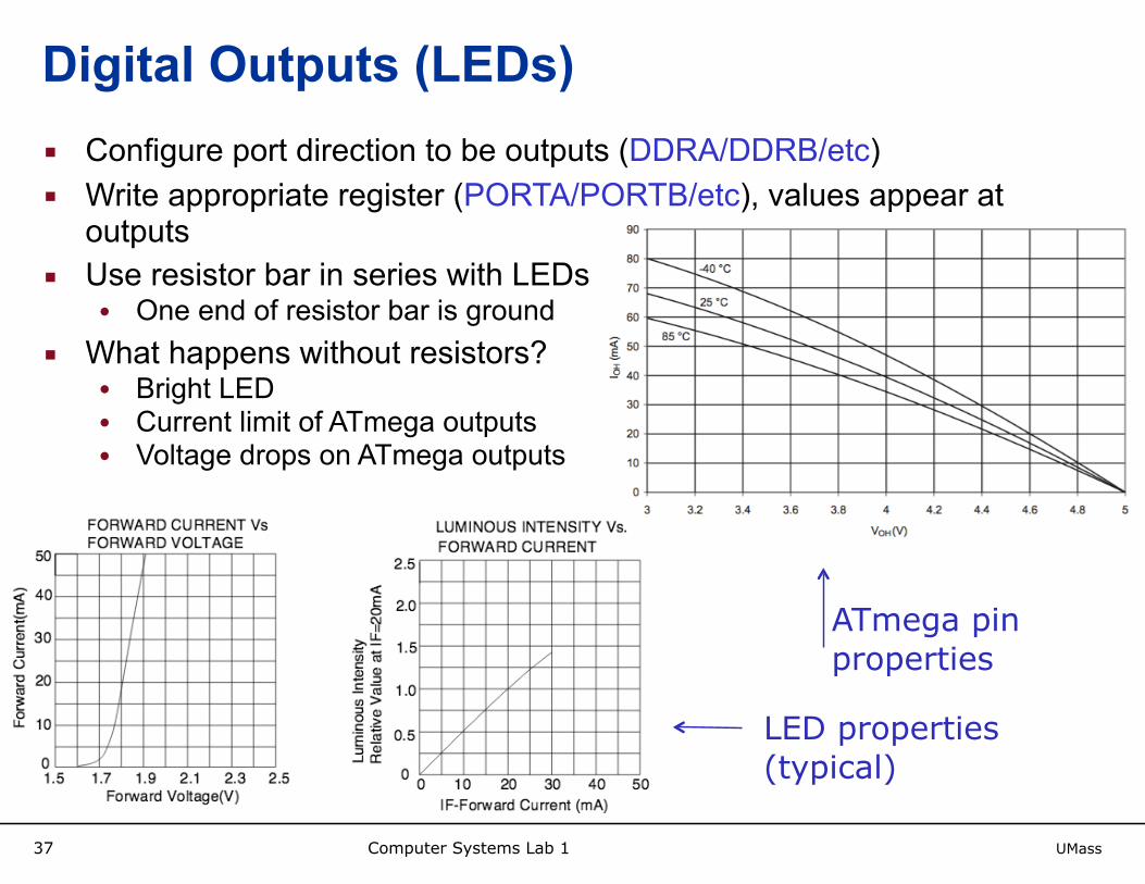
Digital Outputs (LEDs)▪ Configure port direction to be outputs (DDRA/DDRB/etc) ▪ Write appropriate register (PORTA/PORTB/etc), values appear at
outputs ▪ Use resistor bar in series with LEDs
• One end of resistor bar is ground ▪ What happens without resistors?
• Bright LED • Current limit of ATmega outputs • Voltage drops on ATmega outputs
LED properties (typical)
ATmega pin properties

Computer Systems Lab 1 UMass
▪ Configure port directions to be inputs (e.g. DDRA for port A) ▪ Then, a register (e.g. PINA) will contain the input values from pins ▪ Read register to get pin values ▪ Playback and record switches connect pins to either VCC or gnd ▪ Reset uses a button and pull-up circuit (shown below)
38
Digital Inputs (switches)
r = 1k
push-button
VCC
VPIN ≈ VCC or VPIN ≈ 0
reset pin
pull-up resistor
open or shorted
ATmega
input pins

Computer Systems Lab 1 UMass39
Analog Input from Sensor▪ 2 analog inputs will adjust the playback if the modify switch is on
during playback • This allows you to “play” the GME like an instrument • Analog inputs are ignored if modify switch is off
▪ 1st analog input must speed up and slow down playback ▪ You are free to decide how to use the 2nd analog input
• Repeat notes during playback • Change notes • ???

Computer Systems Lab 1 UMass40
Photocell▪ Essentially a light-dependent resistor ▪ Why the squiggly shape?
For a good overview: https://cdn-learn.adafruit.com/assets/assets/000/010/129/original/APP_PhotocellIntroduction.pdf
adafruit.com

Computer Systems Lab 1 UMass41
Analog Input from Photocell▪ Hardware setup translating photocell resistance to analog voltage ▪ Describe analog voltage as function of cell resistance ▪ This setup is called a single-ended conversion, we are measuring the
analog input with respect to ground of microcontroller
http://advancedphotonix.com/wp-content/uploads/PDV-P8103.pdf
r = 20k
photocell
VCC
pin (ADC)
ATmega

Computer Systems Lab 1 UMass42
Analog Input from Sensor▪ Configure chosen pin as analog input (e.g. PORTA) ▪ Select the pin that should be used for ADC (ADMUX) ▪ Start analog-to-digital conversion by setting appropriate bit of status
register (ADCSRA) ▪ Monitor appropriate bit of ADCSRA to wait for conversion to complete
• Could also set an interrupt to occur when conversion finishes ▪ Read out the 10-bit digitized value from ADCL and ADCH after
conversion is complete ▪ Reset ADC for next use
▪ This particular ADC uses successive approximation for conversion • Come see me if you want to know more about it

Computer Systems Lab 1 UMass43
Analog to Digital Conversion
VIN (ADC input voltage)
ADC output code
0x3FF
0x000
0 VREF
0x001
0x002
…
…
…
• What are min and max ADC outputs for photo sensor?
• Does bright light cause high output or low output?
VREF is configurable; can use internal 2.56 V source

Computer Systems Lab 1 UMass44
Programming Tips

Computer Systems Lab 1 UMass45
Pseudocode of a Possible Implementation
Configure timers/USART/interrupts/etcwhile (1) {
if (recording) {USART_Read()EEPROM_Write()
}if (playing) {
EEPROM_Read()if (modifying) {
//modify}USART_Write()
}}

Computer Systems Lab 1 UMass46
Programming Tips: Use of Bitmasks▪ Recall bitwise operators in C
• a = b & c • a = b | c • a = b << c• etc
▪ Bit-check: to check whether a single bit is high/low • (1<<3) is 0b00001000 • PINA & (1 << 3)
• … = 0b00001000 if bit 3 of PINA is 1 • … = 0b00000000 if bit 3 of PINA is 0
▪ Can use “if (PINA & (1 << 3))” as branching condition • (PINA & (1 << 3)) is 0x00 unless pin 3 of PINA is 1• All other bits of PINA are irrelevant
▪ What about if(PINA && (1 << 3))?

Computer Systems Lab 1 UMass47
Programming Tips: Use of Bitmasks▪ Bit-set: to set/clear a single bit while leaving others unchanged
• PORTA |= (1 << 3); // is equivalent to… • PORTA = PORTA|(1 << 3);• …Sets bit 3 high, leaves all other bits unchanged
▪ Just as PORTA is defined to represent a memory location, names are also defined for individual bits of registers • PORTA3 represents the number 3 • PINA |= (1 << PORTA3)• PINB &= ~(1 << PORTB3) //clear bit 3 of port B• PINA |= (1 << PORTB2) // would this work?
▪ Having names for individual bits is very useful in control registers, since the bits there have entirely different meanings if (UCSRA & (1<<RXC)) {
// USART is done receiving}

Computer Systems Lab 1 UMass48
Programming Tips: Appropriate Datatypes▪ 8-bit processor ▪ int is 16 bits ▪ long is 32 bits
▪ May want to use “uint8_t” for 8-bit integer values ▪ May want to use “uint16_t” for 16-bit integer values
▪ e.g. ADC outputs
▪ How are 16-bit types handled on 8-bit processors?

Computer Systems Lab 1 UMass49
Suggestion for Building Project Incrementally
▪ Try example code from this presentation course website • Verify that you can program microcontroller and step through program
▪ Write simple sketch of code • Verify that playback/record switches lead to the expected points in code
▪ Verify that USART receives MIDI correctly • Use watch window or light up LEDs to show received notes
▪ Verify that USART correctly sends MIDI to PC • Start by sending hard-coded constants
▪ Verify that ADC works correctly • Use watch windows or light up LEDs to see ADC output • Check whether ADC value matches applied voltage
▪ Verify functions for reading and writing EEPROM • Simple test routine applying a few values

Computer Systems Lab 1 UMass50
General Advice▪ Consult the Atmega32 datasheet
• Pin layouts • Code examples • Everything you need to manipulate the microcontroller for project is there!
▪ Use the AVR studio debugger • Check the value of pins and registers • Single step through code to find source of problems
▪ Debug with logic analyzer and oscilloscope • Check frequency of USART outputs on scope
▪ Use internet resources • avrfreaks.net is a good resource for examples
▪ Start early and get help early if stuck

Computer Systems Lab 1 UMass51
Tool flow for Putting code onto ATMega32

Computer Systems Lab 1 UMass52
WinAVR▪ WinAVR is a set of development tools for Atmel AVR RISC
microprocessors ▪ Programs written in C, compiled with GCC and avr-libc ▪ Open source, can be obtained at: winavr.sourceforge.net

Computer Systems Lab 1 UMass53
Build Process▪ Board Assembly ▪ C Programming
• WinAVR • AVR Studio version 4 (IDE) • JTAG Programmer
▪ Testing • In-Circuit Emulator • MIDI-OX • Saleae Logic Analyzer
• Instructions on saleae.com • Oscilloscope in lab

Computer Systems Lab 1 UMass54
AVR Studio Demo: Getting Started▪ Open AVR Studio ▪ Create new project ▪ Select AVR GCC for the project type ▪ Type in a project title and choose project directory if necessary ▪ Click next and select the debugging platform (JTAG ICE) used to
program the MCU as well as the MCU that you are using (ATmega32) ▪ Finish

Computer Systems Lab 1 UMass55
AVR Studio Demo: Configure Projectgo to Project —> Configuration Options 1.Choose the appropriate clock frequency for your part 2.Under custom options, should see WinAVR for avr-gcc and make 3.May need to add include directories and libraries if not seeing any external dependency files listed in project after building
1.2.
3.

Computer Systems Lab 1 UMass56
AVR Studio Demo: Program DeviceWrite code, then then… 1.Build your project
2.Connect to the MCU, and then A. Erase the device B. load to flash memory the .hex file
created in your project directory (location of hex file is set through project configuration window)
Now program will start executing!

Computer Systems Lab 1 UMass57
In Circuit Emulator▪ Use ICE to debug code as it runs on ATmega32 ▪ Critical for completing project and diagnosing bugs ▪ Click on triangle to start debug ▪ Use controls to move through code
• Step through code one instruction at a time • Set breakpoints in code
▪ Watch windows to see values of variables changing as program runs

Computer Systems Lab 1 UMass58
ICE Watch Windows
Note: this was compiled with option -o0 to turn off compiler optimization (otherwise var x gets removed by compiler and can’t be added to watch window)

Computer Systems Lab 1 UMass59
MIDI-OX Software▪ Open MIDI device in options menu
▪ Select Yamaha UX16 (if not available, need to install driver)

Computer Systems Lab 1 UMass60
MIDI-OX Software▪ Click on the keyboard button, press key on computer keyboard ▪ Hear sound, and key appears in output monitor ▪ This note was sent to the GME (can see it on scope)
• Note on is a 3-byte message • Note off is a 3-byte message (shortly after the first)
▪ Note will appear on input monitor later when played back from GME

Computer Systems Lab 1 UMass61
Play MIDI File in MIDI-Ox▪ Actions —> Play MIDI opens MIDIBar ▪ Choose file to play in MIDIBar