Embed Size (px)
Citation preview
ECE 331 – Digital Systems Design
Introduction to Sequential Logic Circuits(aka. Finite State Machines)
andFSM Analysis
(Lecture #19)
ECE 331 - Digital Systems Design 2
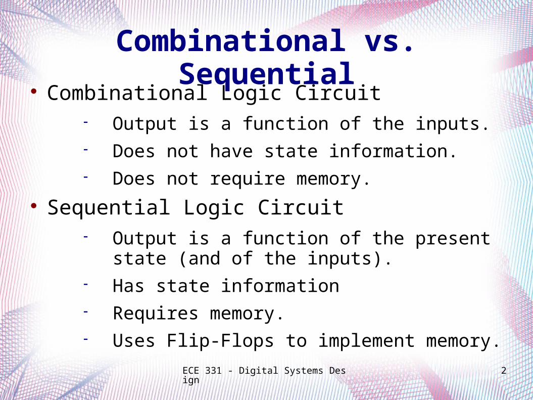
Combinational vs. Sequential Combinational Logic Circuit
Output is a function of the inputs. Does not have state information. Does not require memory.
Sequential Logic Circuit Output is a function of the present state (and
of the inputs). Has state information Requires memory. Uses Flip-Flops to implement memory.
ECE 331 - Digital Systems Design 3
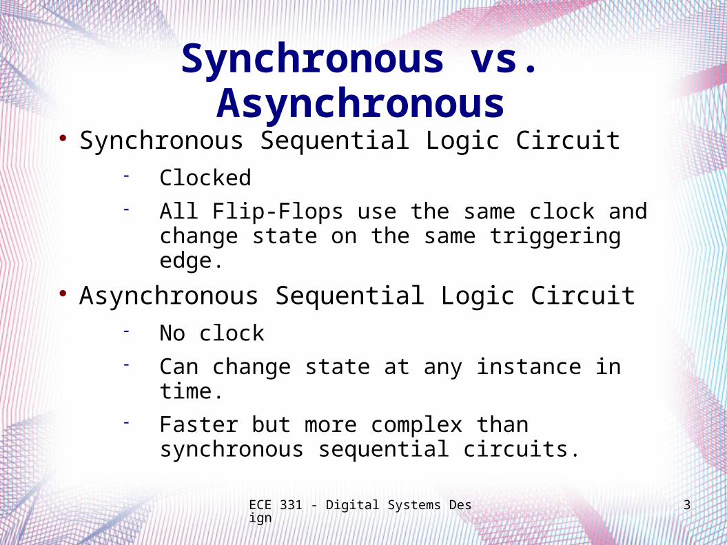
Synchronous vs. Asynchronous Synchronous Sequential Logic Circuit
Clocked All Flip-Flops use the same clock and
change state on the same triggering edge.
Asynchronous Sequential Logic Circuit No clock Can change state at any instance in time. Faster but more complex than
synchronous sequential circuits.
ECE 331 - Digital Systems Design 4
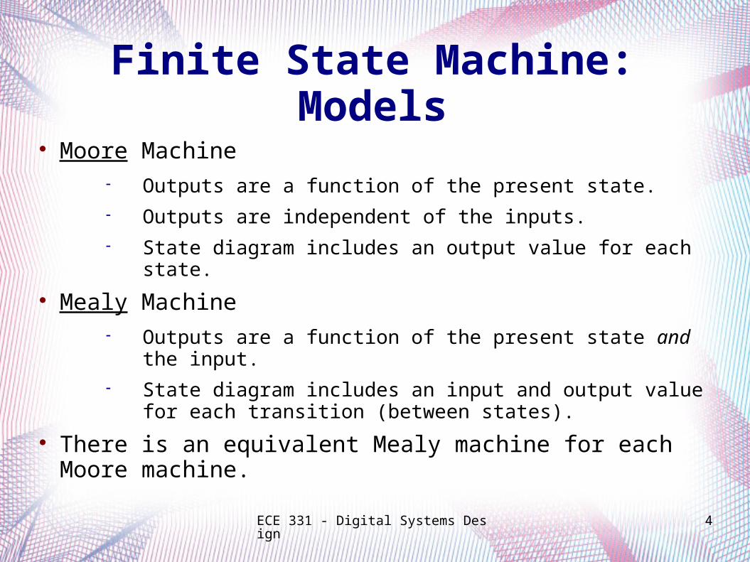
Finite State Machine: Models Moore Machine
Outputs are a function of the present state. Outputs are independent of the inputs. State diagram includes an output value for each state.
Mealy Machine Outputs are a function of the present state and the input. State diagram includes an input and output value for
each transition (between states).
There is an equivalent Mealy machine for each Moore machine.
ECE 331 - Digital Systems Design 5
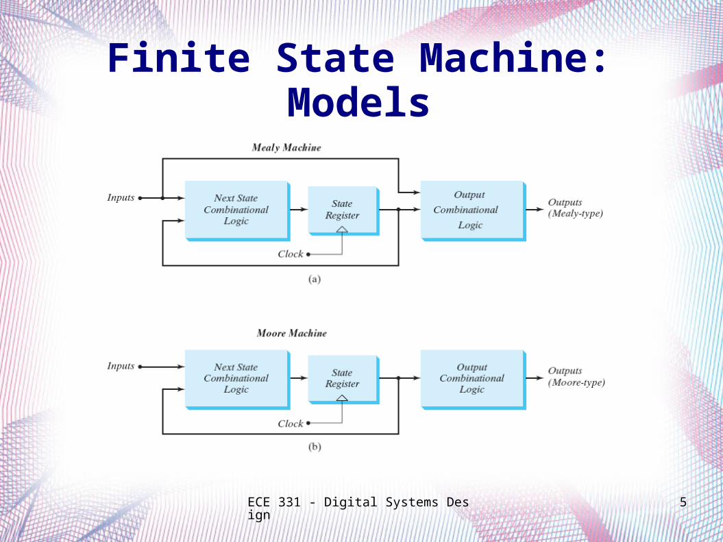
Finite State Machine: Models
ECE 331 - Digital Systems Design 6
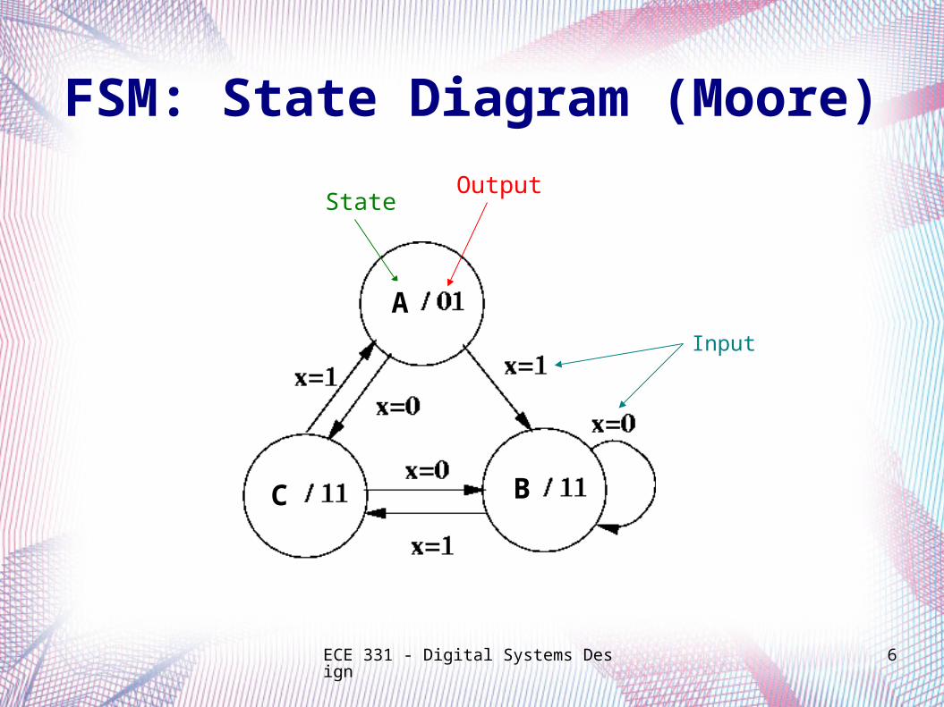
FSM: State Diagram (Moore)
StateOutput
Input
A
BC
ECE 331 - Digital Systems Design 7
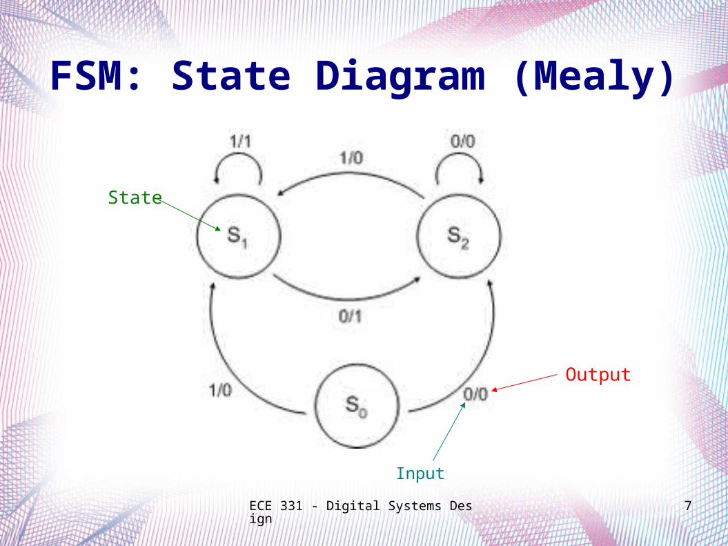
FSM: State Diagram (Mealy)
State
Output
Input
ECE 331 - Digital Systems Design 8
Finite State Machine Analysis
ECE 331 - Digital Systems Design 9
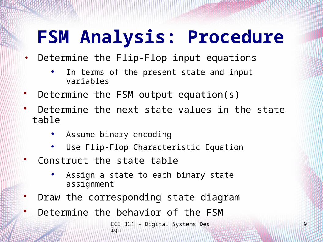
FSM Analysis: Procedure• Determine the Flip-Flop input equations
In terms of the present state and input variables
• Determine the FSM output equation(s)
• Determine the next state values in the state table Assume binary encoding Use Flip-Flop Characteristic Equation
• Construct the state table Assign a state to each binary state assignment
• Draw the corresponding state diagram
• Determine the behavior of the FSM

ECE 331 - Digital Systems Design 10
Example:
FSM using D Flip-Flops
FSM Analysis
11
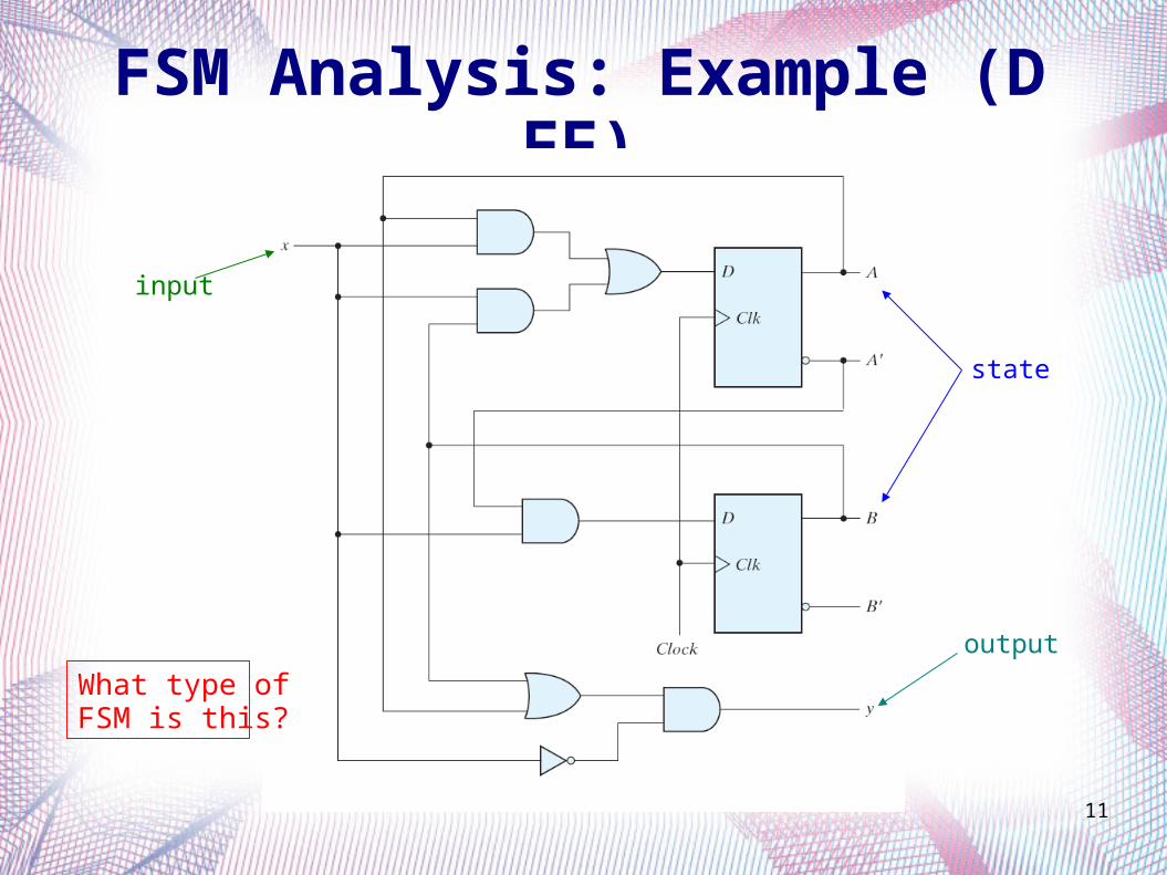
FSM Analysis: Example (D FF)
input
state
output
What type of FSM is this?
ECE 331 - Digital Systems Design 12
FSM Analysis: Example (D FF)
Determine the FF input equations and the FSM output equation(s)
ECE 331 - Digital Systems Design 13
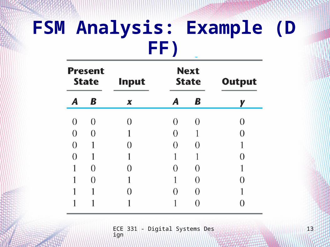
FSM Analysis: Example (D FF)
ECE 331 - Digital Systems Design 14
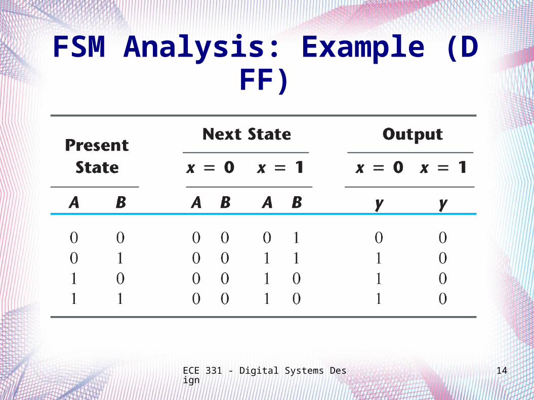
FSM Analysis: Example (D FF)
ECE 331 - Digital Systems Design 15
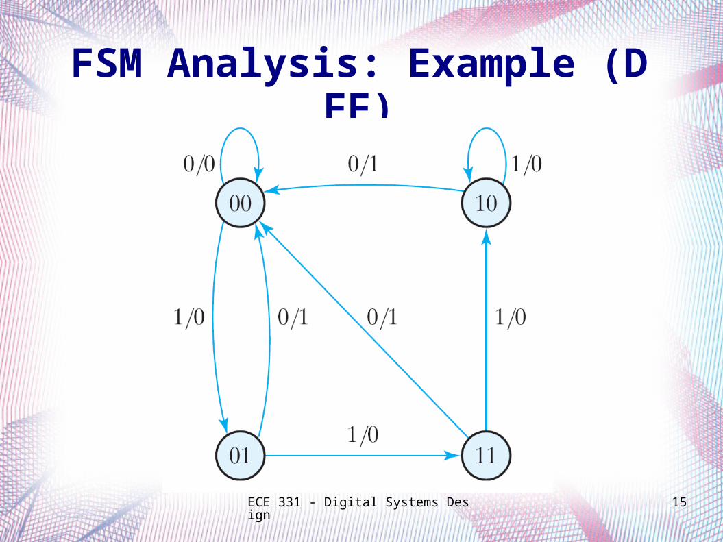
FSM Analysis: Example (D FF)
ECE 331 - Digital Systems Design 16
Example:
FSM using JK Flip-Flops
FSM Analysis
ECE 331 - Digital Systems Design 17
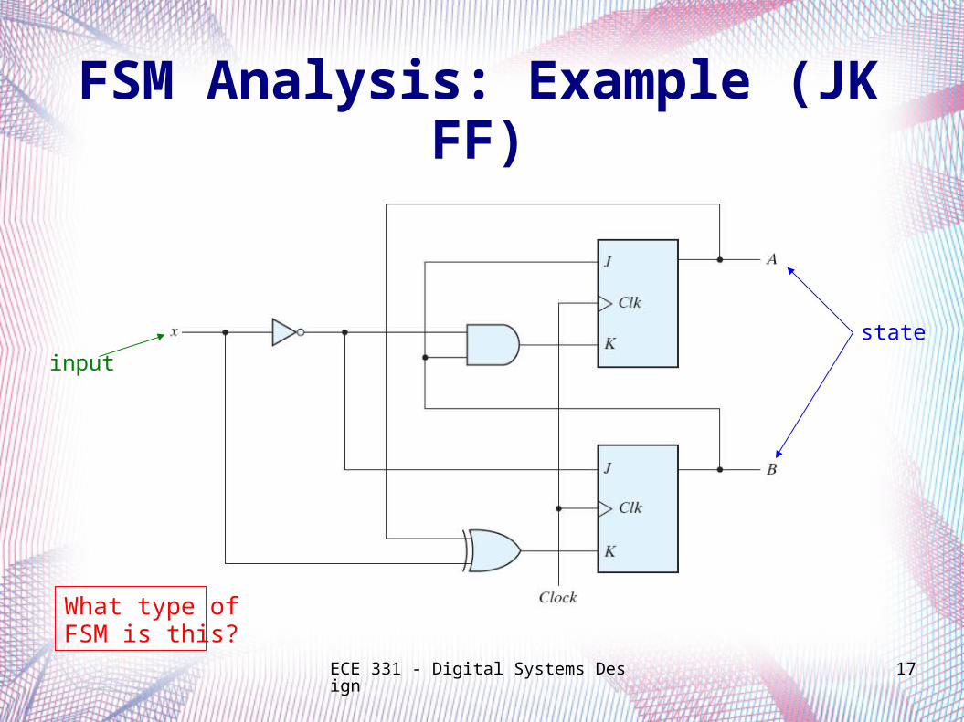
FSM Analysis: Example (JK FF)
input
state
What type of FSM is this?
ECE 331 - Digital Systems Design 18
FSM Analysis: Example (JK FF)
Determine the FF input equations and the FSM output equation(s)
ECE 331 - Digital Systems Design 19
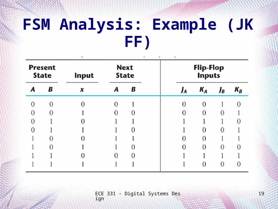
FSM Analysis: Example (JK FF)
ECE 331 - Digital Systems Design 20
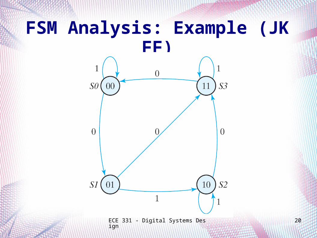
FSM Analysis: Example (JK FF)
ECE 331 - Digital Systems Design 21
Example:
FSM using T Flip-Flops
FSM Analysis
ECE 331 - Digital Systems Design 22
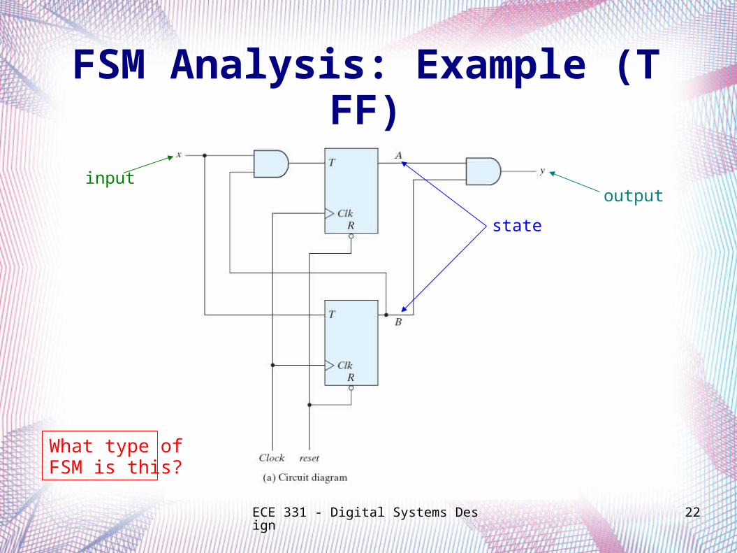
FSM Analysis: Example (T FF)
input
state
output
What type of FSM is this?
ECE 331 - Digital Systems Design 23
FSM Analysis: Example (T FF)
Determine the FF input equations and the FSM output equation(s)
ECE 331 - Digital Systems Design 24
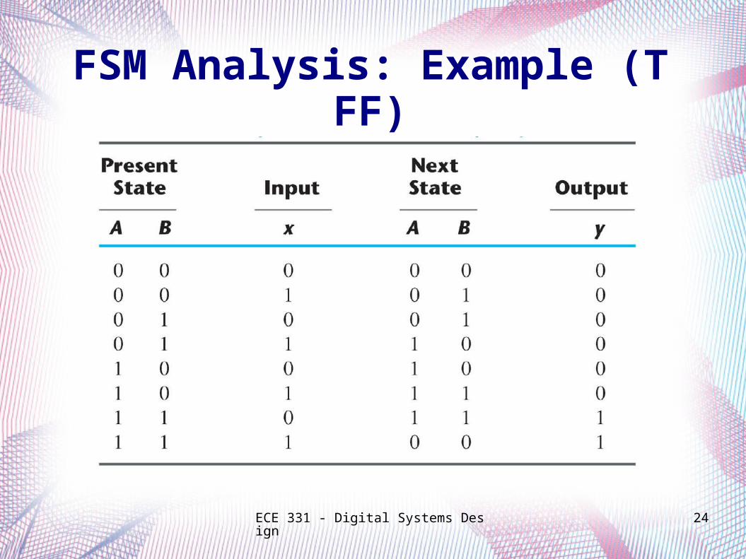
FSM Analysis: Example (T FF)
ECE 331 - Digital Systems Design 25
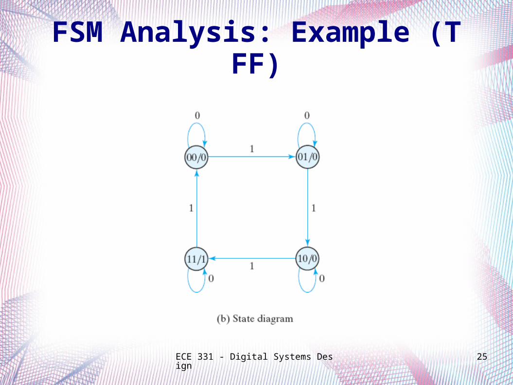
FSM Analysis: Example (T FF)
ECE 331 - Digital Systems Design 26
Acknowledgments
The slides used in this lecture were taken, with permission, from those provided by Pearson Prentice Hall for
Digital Design (4th Edition).
They are the property of and are copyrighted by Pearson Education.


![FSM [Autosaved]](https://img.dokumen.tips/doc/110x75/577cda6c1a28ab9e78a5a27e/fsm-autosaved.jpg)