Embed Size (px)
Citation preview

*28507088_1118*Drive Technology \ Drive Automation \ System Integration \ Services
Operating instructions
ECDriveS®
ECC-DBC Binary Control, ECR Roller Drive , ECG Gearmotor
Edition 11/2018 28507088/EN

SEW-EURODRIVE—Driving the world

Table of contents
Operating instructions – ECDriveS® 3
Table of contents1 General information.................................................................................................................. 5
1.1 About this documentation ............................................................................................... 51.2 Information on this documentation.................................................................................. 51.3 Structure of the safety notes ........................................................................................... 5
1.3.1 Meaning of signal words ................................................................................ 51.3.2 Structure of section-related safety notes........................................................ 51.3.3 Structure of embedded safety notes .............................................................. 6
1.4 Rights to claim under limited warranty ............................................................................ 71.5 Other applicable documentation ..................................................................................... 71.6 Product names and trademarks...................................................................................... 71.7 Copyright notice .............................................................................................................. 7
2 Safety notes .............................................................................................................................. 82.1 Preliminary information ................................................................................................... 82.2 Duties of the user............................................................................................................ 82.3 Target group ................................................................................................................... 82.4 Designated use ............................................................................................................... 92.5 Functional safety technology .......................................................................................... 92.6 Transport....................................................................................................................... 102.7 Installation/assembly..................................................................................................... 10
2.7.1 Restrictions of use........................................................................................ 102.8 Electrical installation ..................................................................................................... 10
2.8.1 Required preventive measure ...................................................................... 102.9 Startup/operation .......................................................................................................... 11
3 Device structure ..................................................................................................................... 123.1 Type code ..................................................................................................................... 12
3.1.1 Type code ECR roller drive .......................................................................... 123.1.2 Type code ECG gearmotor .......................................................................... 133.1.3 Type designation of the controls .................................................................. 13
3.2 Overview of the roller drives ......................................................................................... 143.2.1 ECR roller drive............................................................................................ 143.2.2 ECG gearmotor ............................................................................................ 15
3.3 Overview of the hardware of the ECC-DBC binary control ........................................... 163.4 Definition of the motor direction of rotation ................................................................... 16
4 Installation............................................................................................................................... 174.1 Mechanical installation.................................................................................................. 17
4.1.1 Mounting the ECR roller drive ...................................................................... 174.1.2 Mounting the ECG gearmotor ...................................................................... 204.1.3 Mounting the ECC-DBC binary control ........................................................ 20
4.2 Electrical installation ..................................................................................................... 224.2.1 General information...................................................................................... 224.2.2 Installation instructions................................................................................. 224.2.3 Grounding of switched-mode power supply ................................................. 234.2.4 Terminal designation.................................................................................... 2328
5070
88/E
N –
11/
2018

Table of contents
Operating instructions – ECDriveS®4
4.2.5 Wiring diagrams ........................................................................................... 25
5 Startup ..................................................................................................................................... 265.1 General information ...................................................................................................... 265.2 Setting the DIP switches ............................................................................................... 26
5.2.1 DIP switches 1 to 5: Roller speed ................................................................ 275.2.2 DIP switches 7 to 10: Roller acceleration/deceleration ................................ 28
5.3 Controlling the roller speed ........................................................................................... 29
6 Operation................................................................................................................................. 306.1 Status and error statuses.............................................................................................. 30
7 Inspection/maintenance......................................................................................................... 317.1 Storage ......................................................................................................................... 31
8 Technical data......................................................................................................................... 328.1 Technical data of the ECR roller drive .......................................................................... 32
8.1.1 Electrical data............................................................................................... 328.2 Technical data of the ECG gearmotor .......................................................................... 32
8.2.1 Electrical data............................................................................................... 328.2.2 Pulses per revolution.................................................................................... 33
8.3 Technical data of the ECC-DBC binary control............................................................. 34
2850
7088
/EN
– 1
1/20
18

1General informationAbout this documentation
Operating instructions – ECDriveS® 5
1 General information1.1 About this documentation
The current version of the documentation is the original.This documentation is an integral part of the product. The documentation is intendedfor all employees who perform work on the product.Make sure this documentation is accessible and legible. Ensure that persons respons-ible for the systems and their operation as well as persons who work on the productindependently have read through the documentation carefully and understood it. If youare unclear about any of the information in this documentation, or if you require furtherinformation, contact SEW‑EURODRIVE.
1.2 Information on this documentationThis documentation describes the ECDriveS® roller drive system.This document shows how to install and connect the ECR roller drive/ECG roller gear-motor and how to start up the roller drive system with the ECC-DBC binary control.
1.3 Structure of the safety notes1.3.1 Meaning of signal words
The following table shows the grading and meaning of the signal words for safetynotes.
Signal word Meaning Consequences if disregarded
DANGER Imminent hazard Severe or fatal injuries
WARNING Possible dangerous situation Severe or fatal injuries
CAUTION Possible dangerous situation Minor injuries
NOTICE Possible damage to property Damage to the product or its envi-ronment
INFORMATION Useful information or tip: Simplifieshandling of the product.
1.3.2 Structure of section-related safety notesSection-related safety notes do not apply to a specific action but to several actionspertaining to one subject. The hazard symbols used either indicate a general hazardor a specific hazard.This is the formal structure of a safety note for a specific section:
SIGNAL WORDType and source of hazard.Possible consequence(s) if disregarded.• Measure(s) to prevent the hazard.
2850
7088
/EN
– 1
1/20
18

1 General informationStructure of the safety notes
Operating instructions – ECDriveS®6
Meaning of the hazard symbolsThe hazard symbols in the safety notes have the following meaning:
Hazard symbol MeaningGeneral hazard
Warning of dangerous electrical voltage
Warning of hot surfaces
Warning of automatic restart
1.3.3 Structure of embedded safety notesEmbedded safety notes are directly integrated into the instructions just before the de-scription of the dangerous action.This is the formal structure of an embedded safety note:
SIGNAL WORD Type and source of hazard. Possible consequence(s) if disregar-ded. Measure(s) to prevent the hazard.
2850
7088
/EN
– 1
1/20
18

1General informationRights to claim under limited warranty
Operating instructions – ECDriveS® 7
1.4 Rights to claim under limited warrantyRead the information in this documentation. This is essential for fault-free operationand fulfillment of any rights to claim under limited warranty. Read the documentationbefore you start working with the product.
1.5 Other applicable documentationObserve the corresponding documentation for all further components.
1.6 Product names and trademarks
The brands and product names in this documentation are trademarks or registeredtrademarks of their respective titleholders.
1.7 Copyright notice
© 2018 SEW‑EURODRIVE. All rights reserved. Unauthorized reproduction, modifica-tion, distribution or any other use of the whole or any part of this documentation isstrictly prohibited.
2850
7088
/EN
– 1
1/20
18

2 Safety notesPreliminary information
Operating instructions – ECDriveS®8
2 Safety notes2.1 Preliminary information
The following general safety notes serve the purpose of preventing injury to personsand damage to property. They primarily apply to the use of products described in thisdocumentation. If you use additional components, also observe the relevant warningand safety notes.
2.2 Duties of the userAs the user, you must ensure that the basic safety notes are observed and compliedwith. Make sure that persons responsible for the machinery and its operation as wellas persons who work on the device independently have read through the documenta-tion carefully and understood it.As the user, you must ensure that all of the work listed in the following is carried outonly by qualified specialists:• Setup and installation• Installation and connection• Startup• Maintenance and repairs• Shutdown• DisassemblyEnsure that the persons who work on the product pay attention to the following regula-tions, conditions, documentation, and information:• National and regional safety and accident prevention regulations• Warning and safety signs on the product• All other relevant project planning documents, installation and startup instructions,
and wiring diagrams• Do not assemble, install or operate damaged products• All system-specific specifications and conditionsEnsure that systems in which the product is installed are equipped with additionalmonitoring and protection devices. Observe the applicable safety regulations and le-gislation governing technical work equipment and accident prevention regulations.
2.3 Target group
Specialist for me-chanical work
Any mechanical work may only be performed by adequately qualified specialists. Spe-cialists in the context of this documentation are persons familiar with the design, me-chanical installation, troubleshooting, and maintenance of the product who possessthe following qualifications:• Qualification in the mechanical area in accordance with the national regulations• Familiarity with this documentation
2850
7088
/EN
– 1
1/20
18

2Safety notesDesignated use
Operating instructions – ECDriveS® 9
Specialist for elec-trotechnical work
Any electrotechnical work may only be performed by electrically skilled persons with asuitable education. Electrically skilled persons in the context of this documentation arepersons familiar with electrical installation, startup, troubleshooting, and maintenanceof the product who possess the following qualifications:• Qualification in the electrotechnical area in accordance with the national regula-
tions• Familiarity with this documentation
Additional qualifi-cation
In addition to that, these persons must be familiar with the valid safety regulations andlaws, as well as with the requirements of the standards, directives, and laws specifiedin this documentation. The persons must have the express authorization of the com-pany to operate, program, parameterize, label, and ground units, systems, and circuitsin accordance with the standards of safety technology.
Instructed persons All work in the areas of transportation, storage, operation and waste disposal must becarried out by persons who are trained appropriately. The purpose of the instruction isthat the persons are capable of performing the required tasks and work steps in a safeand correct manner.
2.4 Designated useThe product is intended for installation in electrical plants or machines.In case of installation in electrical systems or machines, startup of the product is pro-hibited until it is determined that the machine meets the requirements stipulated in thelocal laws and directives. For Europe, Machinery Directive 2006/42/EC as well as theEMC Directive 2014/30/EU apply. Observe EN 60204-1 (Safety of machinery -– elec-trical equipment of machines).The standards given in the declaration of conformity apply to the product.The product is designed for stationary use.Technical data and information on the connection conditions are provided on thenameplate and in chapter "Technical data" in the documentation. Always comply withthe data and conditions.Unintended or improper use of the product may result in severe injury to persons anddamage to property.
2.5 Functional safety technologyThe product must not perform any safety functions without a higher-level safety sys-tem, unless explicitly allowed by the documentation.
2850
7088
/EN
– 1
1/20
18

2 Safety notesTransport
Operating instructions – ECDriveS®10
2.6 Transport
Inspect the shipment for damage as soon as you receive the delivery. Inform the ship-ping company immediately about any damage. If the product is damaged, it must notbe assembled, installed or started up.Observe the following notes when transporting the device:• Ensure that the product is not subject to mechanical impact.• Before transportation, cover the connections with the supplied protection caps.• Only place the product on the cooling fins or on the side without connectors during
transportation.• Always use lifting eyes if available.If necessary, use suitable, sufficiently dimensioned handling equipment.Observe the information on climatic conditions in chapter "Technical data" of the docu-mentation.
2.7 Installation/assemblyEnsure that the product is installed and cooled according to the regulations in the doc-umentation.Protect the product from strong mechanical strain. The product and its mounting partsmust never protrude into the path of persons or vehicles. Ensure that components arenot deformed and insulation spaces are not changed, particularly during transportationand handling. Electric components must not be mechanically damaged or destroyed.Observe the notes in chapter "Mechanical installation" (→ 2 17) in the documenta-tion.
2.7.1 Restrictions of useThe following applications are prohibited unless explicitly permitted:• Use in potentially explosive areas• Use in areas exposed to harmful oils, acids, gases, vapors, dust, and radiation• Operation in applications with impermissibly high mechanical vibration and shock
loads in excess of the regulations stipulated in EN 61800-5-1• Use at an elevation of more than 1000 m above sea level
2.8 Electrical installation
Ensure that all of the required covers are correctly attached after carrying out the elec-trical installation.Make sure that preventive measures and protection devices comply with the applic-able regulations (e.g. EN 60204-1 or EN 61800-5-1).
2.8.1 Required preventive measureUse the drive system only in systems that comply with the requirements of protectionclass 3 according to EN 61140, e.g. SELV.
2850
7088
/EN
– 1
1/20
18

2Safety notesStartup/operation
Operating instructions – ECDriveS® 11
2.9 Startup/operationObserve the safety notes in the chapters "Startup" (→ 2 26) and "Opera-tion" (→ 2 30) in the documentation.Ensure that all required covers are mounted properly before applying the supplyvoltage.Depending on the degree of protection, products may have live, uninsulated, andsometimes moving or rotating parts, as well as hot surfaces during operation.In the event of deviations from normal operation, switch the product off. Possible devi-ations are increased temperatures, noise, or vibration, for example. Determine thecause. Contact SEW‑EURODRIVE if necessary.Mechanical blocking or internal protective functions of the product can cause a motorstandstill. Eliminating the cause of the problem or performing a reset may result in thedrive restarting automatically. If, for safety reasons, this is not permitted for the drive-controlled machine, first disconnect the product from the supply system and then starttroubleshooting.Risk of burns: The surface temperature of the product can exceed 60 °C during opera-tion. Do not touch the product during operation. Let the product cool down beforetouching it.
2850
7088
/EN
– 1
1/20
18

3 Device structureType code
Operating instructions – ECDriveS®12
3 Device structure
3.1 Type code3.1.1 Type code ECR roller drive
Example: ECR-A2M-50-450-045-Z-A-V1Product family EC EC = ECDriveS® device familyProduct type R R = Roller
DesignA • A = IP54 degree of protection (standard)
• W = IP66 degree of protection (wet area application)• Z = Operation up to -30 °C (deep-freezing application)
Voltage 2 2 = 24 VMotor connection M Motor cable M8, 1000 mm
Roller diameter 50 • 50 = 50 mm• 48 = 48.6 mm1)
Length between frames 450 Roller length in mm
Speed class
045 Speed in m/min• 015• 020• 025• 035• 045• 060• 075• 095• 125• 175• 215
Tube options
Z • Z = Galvanized steel (standard)• J = Stainless design• U = PUR coating 2 mm• P = PVC hose 2 mm• K = Cone 1.8° on galvanized steel• C = Cone 1.8° on steel in stainless steel design• D = PVC hose on steel in stainless steel design• E = PUR hose on steel in stainless steel design• X = Special design
Axis design
A • A =Cable side: M12×1.25 on 11 mm hexagonOpposite side: M8 female thread
• B =Cable side: M12×1.25 on 11 mm hexagonOn the opposite side: Smooth 11 mm spring-loaded hexagon axis
Transmission heads
V1 • A0 = Smooth tube without groove or drive head• V1 = Drive head for Poly-V-belt in shape PJ according to DIN 7867• G0 = Tube with groove head• G1 = Grooved tube with groove position 50/80• GX = Grooved tube with special groove position
1) Only available in the USA (1.9 inch).
2850
7088
/EN
– 1
1/20
18

3Device structureType code
Operating instructions – ECDriveS® 13
3.1.2 Type code ECG gearmotorExample: ECG-A2M-67-A-K0
Product family EC EC = ECDriveS® device familyProduct type G G = GearmotorDesign A A = IP54 degree of protectionVoltage 2 2 = 24 VMotor options M M8 plug connector
Gear unit ratio
67 Gear ratio i:• 67• 45• 33• 27• 18• 15• 11• 9
Version A A = Standard mounting 4xM5x7Output shaft K0 K = Key
X Special design
3.1.3 Type designation of the controls• ECC-DBC-24-00: Binary control• ECC-DFC-24-00: Fieldbus controller
2850
7088
/EN
– 1
1/20
18

3 Device structureOverview of the roller drives
Operating instructions – ECDriveS®14
3.2 Overview of the roller drives3.2.1 ECR roller drive
[1] [2] [3] [2]
19809722123
[1] Electrical connection[2] Axis journal[3] Motor roller
Nameplate
1 0 0 10 A 1
DC24V3
XX
XXXX-XXX-XX-XX-XX
XXX
[1]
[2][3]
19516478219
[1] Type designation, e.g.: ECR-A2M-50-450-045-Z-B-V0[2] Voltage[3] Serial number
2850
7088
/EN
– 1
1/20
18

3Device structureOverview of the roller drives
Operating instructions – ECDriveS® 15
3.2.2 ECG gearmotor[1] [2] [3]
19809719179
[1] Electrical connection[2] Gearmotor[3] Motor shaft
Nameplate
19516434699
2850
7088
/EN
– 1
1/20
18

3 Device structureOverview of the hardware of the ECC-DBC binary control
Operating instructions – ECDriveS®16
3.3 Overview of the hardware of the ECC-DBC binary control
24 VECC-DBC-24-00
21 43 65 87 109
0 V
[1][2]
[5] [3][4][6][7][8]
[9]
25852264587
[1] Removable feed-in terminal 24 V[2] Removable I/O terminal strip[3] LED “Overtemperature”[4] Operation LED[5] DIP switch[6] LED "Start"[7] LED "Hold"[8] LED "Stop"[9] ECR or ECG roller drive connection
3.4 Definition of the motor direction of rotationThe definition of the motor direction of rotation is based on the view of the motor rollerfrom the cable output side.• Clockwise (CW)• Counter-clockwise (CCW)
2850
7088
/EN
– 1
1/20
18
4InstallationMechanical installation
Operating instructions – ECDriveS® 17
4 Installation
4.1 Mechanical installation
4.1.1 Mounting the ECR roller drive
CAUTIONImproper fixation of the axis can destroy the motor roller.Possible damage to property.• Make sure not to damage the cable during assembly.• Ensure the correct torque for the screw connections.• Do not use an impact screwdriver to tighten the screws and nuts.
INFORMATIONThe procedure for the mechanical installation depends on the design of the motorroller.
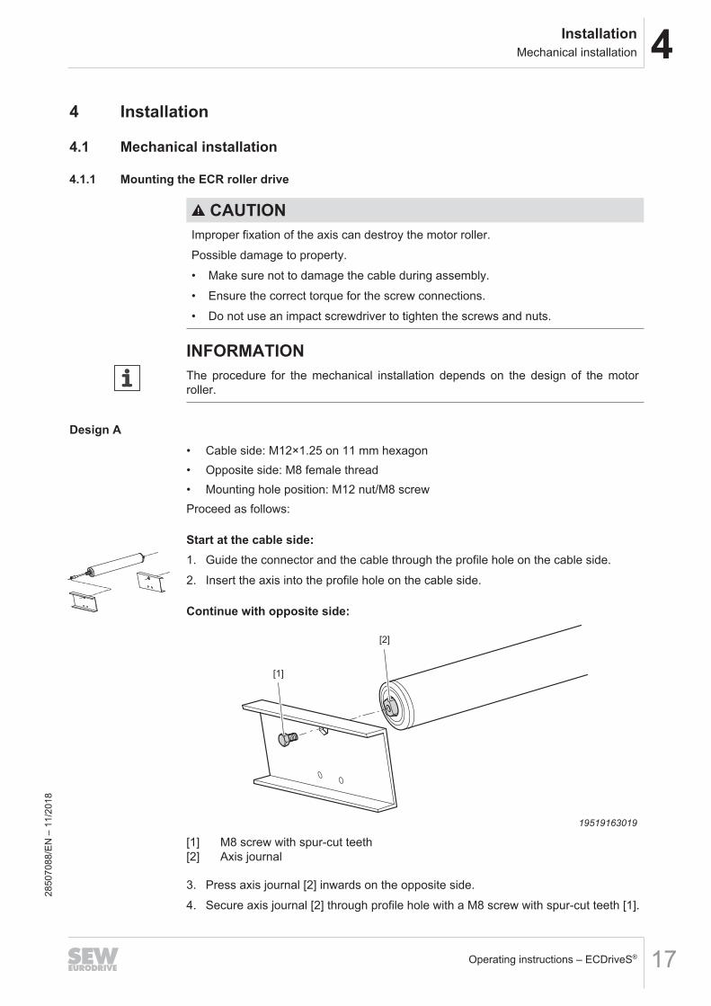
Design A• Cable side: M12×1.25 on 11 mm hexagon• Opposite side: M8 female thread• Mounting hole position: M12 nut/M8 screwProceed as follows:
Start at the cable side:1. Guide the connector and the cable through the profile hole on the cable side.2. Insert the axis into the profile hole on the cable side.
Continue with opposite side:
[1]
[2]
19519163019
[1] M8 screw with spur-cut teeth[2] Axis journal
3. Press axis journal [2] inwards on the opposite side.4. Secure axis journal [2] through profile hole with a M8 screw with spur-cut teeth [1].
2850
7088
/EN
– 1
1/20
18

4 InstallationMechanical installation
Operating instructions – ECDriveS®18
Continue with cable side:
[1]
[2]
19844223243
[1] M12 flange nut[2] Axis
5. Screw the flange nut [1] from outside onto the axis [2] on the cable side.6. Grip axis [2] from inside with a suitable tool and tighten the flange nut [1] with a
tightening torque of 50 Nm.
Continue with opposite side:7. Grip axis journal [2] from inside on the opposite side with a suitable tool and
tighten the screw with spur-cut teeth [1] from outside with a tightening torque of10 – 14 Nm.
Design B• Cable side: M12×1.25 on 11 mm hexagon• On the opposite side: smooth 11 mm spring-loaded hexagon axis• Mounting hole position: M12 nutProceed as follows:
Start at the cable side:1. Guide the connector and the cable through the profile hole on the cable side.2. Insert the axis into the profile hole on the cable side.
2850
7088
/EN
– 1
1/20
18

4InstallationMechanical installation
Operating instructions – ECDriveS® 19
Continue with opposite side:
[1]
[2]
19520502923
[1] Profile hole[2] Spring axis
3. Press spring axis [2] inwards on the opposite side and insert the motor roller intothe conveyor.
4. When the motor roller reaches its proper position on the profile hole [1], releasespring axis [2].
Continue with cable side:
[1]
[2]
19844223243
[1] M12 flange nut[2] Axis
5. Screw the flange nut [1] from outside onto the axis [2] on the cable side.6. Grip axis [2] from inside with a suitable tool and tighten the flange nut [1] with a
tightening torque of 50 Nm.
2850
7088
/EN
– 1
1/20
18

4 InstallationMechanical installation
Operating instructions – ECDriveS®20
4.1.2 Mounting the ECG gearmotor
CAUTIONSharp edges due to open keyway.Cuts.• Insert the key into the keyway.• Pull a protective tubing over the shaft.
4 x M5
19516487947
Proceed as follows:1. Place the gearmotor onto the carrier plate.2. Secure the gearmotor with four M5 screws with spring washers as threadlocker.3. Tighten the screws with a tightening torque of 2.5 – 3.5 Nm.
Permitted mounting positionsIn general, only mounting positions M1, M3, M5 and M6 are approved. ContactSEW‑EURODRIVE when using the ECG gearmotor in mounting position M2 or M4.
4.1.3 Mounting the ECC-DBC binary controlThe ECC-DBC binary control must be mounted with its long side in parallel to the con-veyor belt. The plate of the heat sink of the binary control must be in contact with theframe of the conveyor belt. Secure the binary control with screws to the frame of theconveyor belt. Guide the screws through both mounting bores of the binary control aswell as through matching bores drilled in the frame of the conveyor belt.Observe the following mounting instructions:• The metal surface of the heat sink must point to the frame of the conveyor belt.
The heat sink must only be accessible if the binary control has been removed fromthe frame of the conveyor belt.
• The binary control must be installed on a grounded metal surface or must have aconducting wire that establishes a ground connection to the heat sink of the binarycontrol.
• The binary control must be installed in such a way that the operator can easily andwithout any hindrance disconnect the current supply connector, the motor con-nector, and the control signal connector.
• The binary control must be easily accessible.
2850
7088
/EN
– 1
1/20
18

4InstallationMechanical installation
Operating instructions – ECDriveS® 21
ECC-DBC-24-00
21 43 65 87 109
[1]
[1]
19852798219
[1] Mounting holes Ø 6 mm
[1]
[2]
19852794507
[1] Frame of the conveyor belt[2] Binary control with metal plate as heat sink
2850
7088
/EN
– 1
1/20
18

4 InstallationElectrical installation
Operating instructions – ECDriveS®22
4.2 Electrical installation
4.2.1 General informationThe motor roller’s input end of the shaft and/or the mounting bracket must be electri-cally connected with the grounded frame of the conveyor belt.
WARNINGRisk of crushing if the drive starts up unintentionally.Severe or fatal injuries.• Before you start working on the unit, disconnect the motor and all connected op-
tions from the power supply.• Secure the motor against unintended power-up.
WARNINGElectric shock due to faulty ground connection or equipotential bonding.Severe or fatal injuries.• Make sure to install the ground connection and equipotential bonding correctly.
NOTICEDanger due to incorrect dimensioning of the current supply.Damage to property• Before starting installation work, familiarize yourself with the power requirements
of the motors.• Make sure that the current supply and the wiring are correctly dimensioned on
the basis of the applicable directives and standards.
4.2.2 Installation instructionsThe nominal voltage of the ECDriveS® control must correspond to the data for the sup-ply voltage.Dimension the cable cross section according to the input current I1 of the inverter (seechapter "Technical data" (→ 2 32)).ECDriveS® is an enclosed drive system. Therefore, you must only connect ECR orECG motors from SEW‑EURODRIVE to the motor connections.Use the ECDriveS® drive system only in systems that comply with the requirements ofprotection class 3 according to EN 61140, e.g. SELV.Thermal overload protection of the connection lead shall be provided by at least one ofthe following means:• The maximum output current of the 24 V switched-mode power supply is limited to
the value of the maximum current carrying capacity of the connected conductor.• Fuses in utilization category gG• Type C miniature circuit breaker
2850
7088
/EN
– 1
1/20
18

4InstallationElectrical installation
Operating instructions – ECDriveS® 23
4.2.3 Grounding of switched-mode power supplyAccording to the requirements for a SELV system, the mass connections of the outputchannels must be connected with the ground potential of the switched-mode powersupply (SMPS).
[1]
+ -
[1]
- +
25884830987
[1] Switched-mode power supply
If several switched-mode power supplies are connected in parallel, the mass connec-tions of at least one device must be grounded.
4.2.4 Terminal designation
24 VECC-DBC-24-00
21 43 65 87 109
0 V
[1][2]
25852312459
[1] Removable feed-in terminal 24 V[2] Removable E/A terminal strip
Removable feed-in terminal [1]This is a removable 2-pin connector with screw terminals. Cable sizes are within therange of 0.4 mm2 and 1.5 mm2 (28 AWG and 16 AWG). The terminal assignment isshown in the illustration.
2850
7088
/EN
– 1
1/20
18

4 InstallationElectrical installation
Operating instructions – ECDriveS®24
Removable I/O terminal strip [2]This is a removable 5-pin connector with screw terminals. Cable sizes are within therange of 0.4 mm2 and 1.5 mm2 (28 AWG and 16 AWG).
[1]
[2]
[3]
[4]
[5]
19853478795
[1] Provides +24 V output voltage if error state is active
[2] +24 V input voltage activates speed control (see section Run A and Run B)
[3] +24 V input voltage activates speed control (see section Run A and Run B)
[4] At an input voltage of +24 V, the motor runs against the direction selected onDIP switch 6
[5] 0 V ground connection
Run A Run B DescriptionON OFF Motor roller starts and runs with 100% of the speed selected on DIP
switches 1 to 5
OFF ON Motor roller starts and runs with 50% of the speed selected on DIPswitches 1 to 5
ON ON Motor roller starts and runs with 75% of the speed selected on DIPswitches 1 to 5
OFF OFF Motor roller stops
2850
7088
/EN
– 1
1/20
18

4InstallationElectrical installation
Operating instructions – ECDriveS® 25
4.2.5 Wiring diagramsFor the terminal assignment of the feed-in terminal and the I/O terminal strip, refer tochapter "Terminal designation" (→ 2 23).
PNP module with RUN/REVERSE wiring
ECC-DBC-24-00
21 43 65 87 109
DC 24 V
19886800779
As a requirement for the direction of rotation reversal using the "reverse" input, "RUNA" or "RUN B" must be activated.Observe that the roller drive must be stopped before the direction of rotation is re-versed.
PNP module with error output wiring
ECC-DBC-24-00
21 43 65 87 109
[1]
19886797835
[1] Max. 100 mA
For this connection, the current must not exceed 100 mA. If the device connected withthe error output requires a higher current, an interface relay must be used in between.
2850
7088
/EN
– 1
1/20
18

5 StartupGeneral information
Operating instructions – ECDriveS®26
5 Startup
5.1 General information
WARNINGRisk of crushing if the drive starts up unintentionally.Severe or fatal injuries.• Before you start working on the unit, disconnect the motor and all connected op-
tions from the power supply.• Secure the motor against unintended power-up.
CAUTIONThe surfaces on the drive can be very hot during operation.Risk of burns.• Let the motor cool down sufficiently before you start working on it.
5.2 Setting the DIP switches
24 VECC-DBC-24-00
21 43 65 87 109
0 V
[1]
25852135947
[1] DIP switch
There is an expandable and transparent protection cover above the DIP switches andthe LED field of the binary control. Open the protection cover from the lower edge ofthe binary control to operate the DIP switches. Make sure that the cover is closed pro-perly after setting the DIP switches.
DIP switch Function Button positionOFF ON
1
Speed selection See section DIP switches 1 to 5: Roller speed
2
3
4
5
6 Direction of rotation CW CCW
2850
7088
/EN
– 1
1/20
18

5StartupSetting the DIP switches
Operating instructions – ECDriveS® 27
DIP switch Function Button positionOFF ON
7
Selection acceleration/de-celeration
See section DIP switches 7 to 10: Rolleracceleration/deceleration
8
9
10
5.2.1 DIP switches 1 to 5: Roller speed
S1 S2 S3 S4 S5 Motor speed in min-1
- - - - - 580- - - - x 800- - - x - 1000- - - x x 1200- - x - - 1400- - x - x 1600- - x x - 1800- - x x x 2000- x - - - 2200- x - - x 2400- x - x - 2600- x - x x 2800- x x - - 3000- x x - x 3200- x x x - 3400- x x x x 3600x - - - - 3800x - - - x 4000x - - x - 4200x - - x x 4400x - x - - 4600x - x - x 4800x - x x - 4900x - x x x 5000x x - - - 5100x x - - x 5200x x - x - 5300x x - x x 5400x x x - - 5500x x x - x 5600x x x x - 5700x x x x x 5800
x = ON- = OFF
2850
7088
/EN
– 1
1/20
18

5 StartupSetting the DIP switches
Operating instructions – ECDriveS®28
5.2.2 DIP switches 7 to 10: Roller acceleration/deceleration
S7 S8 S9 S10 acceleration/deceleration time in s- - - - 0.05- - - x 0.1- - x - 0.2- - x x 0.3- x - - 0.4- x - x 0.5- x x - 0.6- x x x 0.7x - - - 0.8x - - x 1x - x - 1.2x - x x 1.4x x - - 1.6x x - x 1.8x x x - 2x x x x 2.5
x = ON- = OFF
Notice: The specified time in seconds applies to the acceleration and to the decelera-tion.
2850
7088
/EN
– 1
1/20
18

5StartupControlling the roller speed
Operating instructions – ECDriveS® 29
5.3 Controlling the roller speedTo calculate the roller speed based on the motor speed selected on DIP switchswitches 1 to 5, the diameter of the respective roller as well as the gear unit reductionratio of the motor roller must be known.The following table shows the speed classes of the ECR motor rollers and their re-spective reduction ratios.
Speed class Gear unit reduction ratio10 67.22 : 1
15 45 : 1
20 32.94 : 1
25 27 : 1
35 18.3 : 1
45 15 : 1
60 10.98 : 1
75 9 : 1
95 6.818 : 1
125 5 : 1
175 3.66 : 1
215 3 : 1
The formula for calculating the roller speed in meters per seconds:
v =n
i
D
60
Mot roller
× ×
π
20132896779
The following example shows the calculation for one roller with the speed class 75 and50 mm roller diameter at 5000 min-1:
5000
9
0 05
60
× ×
=π
.1.45 m/s
20132978059
2850
7088
/EN
– 1
1/20
18
6 OperationStatus and error statuses
Operating instructions – ECDriveS®30
6 Operation
6.1 Status and error statuses
24 VECC-DBC-24-00
21 43 65 87 109
0 V
[5][4][3][2][1]
25852351627
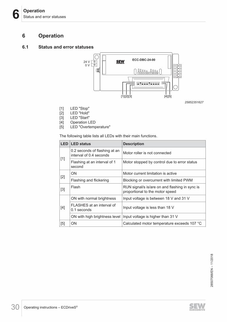
[1] LED "Stop"[2] LED "Hold"[3] LED "Start"[4] Operation LED[5] LED "Overtemperature"
The following table lists all LEDs with their main functions.
LED LED status Description
[1]
0.2 seconds of flashing at aninterval of 0.4 seconds Motor roller is not connected
Flashing at an interval of 1second
Motor stopped by control due to error status
[2]ON Motor current limitation is active
Flashing and flickering Blocking or overcurrent with limited PWM
[3] Flash RUN signal/s is/are on and flashing in sync isproportional to the motor speed
[4]
ON with normal brightness Input voltage is between 18 V and 31 V
FLASHES at an interval of0.1 seconds Input voltage is less than 18 V
ON with high brightness level Input voltage is higher than 31 V
[5] ON Calculated motor temperature exceeds 107 °C
2850
7088
/EN
– 1
1/20
18

7Inspection/maintenanceStorage
Operating instructions – ECDriveS® 31
7 Inspection/maintenance
WARNINGRisk of crushing if the drive starts up unintentionally.Severe or fatal injuries.• Before you start working on the unit, disconnect the motor and all connected op-
tions from the power supply.• Secure the motor against unintended power-up.
CAUTIONThe surfaces on the drive can be very hot during operation.Risk of burns.• Let the motor cool down sufficiently before you start working on it.
If necessary, all components of the ECDriveS® system are replaced. It is not plannedto have the components repaired.
7.1 Storage• Never store the roller motor / gearmotor and the modules of the control in the
open.• Store the roller motor / gearmotor and the modules of the control in a temperature
range of -30 °C to +70 °C and a relative humidity of 10% to 90% (non-condens-ing).
2850
7088
/EN
– 1
1/20
18

8 Technical dataTechnical data of the ECR roller drive
Operating instructions – ECDriveS®32
8 Technical data
8.1 Technical data of the ECR roller drive8.1.1 Electrical data
ECR-A2M-..Voltage: DC 24 V
Nominal mechanical output power at 25 °C: 40 W
Nominal current: 2.5 A
Maximum starting current: 7.2 A
Ambient temperatures: -10 °C – 40 °C
Humidity: 10 to 90%, not condensing
Degree of protection: IP54, optional IP66
Maximum motor cable length: 5 m
8.2 Technical data of the ECG gearmotor8.2.1 Electrical data
ECG-A2M-..Voltage: DC 24 V
Nominal mechanical output power at 25 °C: 40 W
Nominal current: 2.5 A
Maximum starting current: 7.2 A
Ambient temperatures: -10 °C – 40 °C
Humidity: 10 to 90%, not condensing
Degree of protection: IP54, optional IP66
Maximum motor cable length: 5 m28
5070
88/E
N –
11/
2018

8Technical dataTechnical data of the ECG gearmotor
Operating instructions – ECDriveS® 33
8.2.2 Pulses per revolution
Nominal gear ra-tio
Real gear ratio Pulses per revolution Gear unit back-lash in degrees
67 67.221) 2009 4.8
45 45.00 1350 5.1
33 32.94 988 5.1
27 27.00 810 5.1
18 18.331) 549 4.5
15 15.00 450 4.7
11 10.98 329 4.7
9 9.00 270 4.71) Infinite gear unit ratio (67.22 = 67 2/9, 18.33 = 18 1/3)
2850
7088
/EN
– 1
1/20
18
8 Technical dataTechnical data of the ECC-DBC binary control
Operating instructions – ECDriveS®34
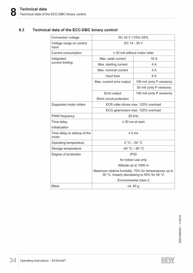
8.3 Technical data of the ECC-DBC binary control
Connection voltage DC 24 V +15%/-25%
Voltage range on controlinput
DC 14 ‑ 30 V
Current consumption ≈ 30 mA without motor roller
Integratedcurrent limiting
Max. peak current 16 A
Max. starting current 4 A
Max. nominal current 3 A
Input fuse 8 A
Max. current error output 100 mA (only P versions)
50 mA (only P versions)
Error outputShort circuit protection
150 mA (only P versions)
Supported motor rollers ECR roller drives max. 120% overload
ECG gearmotors max. 120% overload
PWM frequency 20 kHz
Time delayInitialization
≤ 20 ms at start
Time delay to startup of themotor
≤ 5 ms
Operating temperature 0 °C – 50 °C
Storage temperature -40 °C – 85 °C
Degree of protection IP20for indoor use only
Altitude up to 1000 mMaximum relative humidity: 70% for temperatures up to
30 °C, linearly decreasing to 50% for 50 °CEnvironmental class 2
Mass ca. 60 g
2850
7088
/EN
– 1
1/20
18


SEW-EURODRIVE—Driving the world
SEW-EURODRIVE GmbH & Co KGErnst-Blickle-Str. 4276646 BRUCHSALGERMANYTel. +49 7251 75-0Fax +49 7251 [email protected]