Embed Size (px)
Citation preview

ECdrive T2ECdrive T2-FR
EN Installation and service instructions
180347-00

ECdrive T2
2
Contents
1 Introduction...............................................................................................................................................................41.1 Symbols and illustrations ..............................................................................................................................................................................41.2 Revisions and validity .....................................................................................................................................................................................41.3 Product liability .................................................................................................................................................................................................41.4 Reference documents .....................................................................................................................................................................................4
2 Fundamental safety precautions .......................................................................................................................52.1 Intended use.......................................................................................................................................................................................................52.2 Safety notices .....................................................................................................................................................................................................52.3 Safety-conscious working .............................................................................................................................................................................62.4 Environmentally conscious working .........................................................................................................................................................62.5 Safety instructions related to transportation and storage ...............................................................................................................62.6 Qualification .......................................................................................................................................................................................................6
3 About this document .............................................................................................................................................73.1 Overview ..............................................................................................................................................................................................................7
4 Overview.....................................................................................................................................................................84.1 Diagrams ..............................................................................................................................................................................................................84.2 Tools and aids .....................................................................................................................................................................................................94.3 Torques .................................................................................................................................................................................................................94.4 Components and assembly groups ...........................................................................................................................................................9
5 Installation ............................................................................................................................................................... 105.1 Preparations to be made on site .............................................................................................................................................................. 105.2 Preparing the track ....................................................................................................................................................................................... 105.3 Checking/preparing cable routing ......................................................................................................................................................... 105.4 Mount intermediate plates (optional) ....................................................................................................................................................115.5 Mounting the track ........................................................................................................................................................................................125.6 Installing the angled floor guide ..............................................................................................................................................................135.7 Fitting the door leaves ..................................................................................................................................................................................135.7.1 Mount the single roller carriage on the door leaf ..............................................................................................................................135.7.2 Fitting the door leaf with single roller carriage ...................................................................................................................................145.7.3 Mount the support bracket for the double roller carriage on the leaf. ......................................................................................155.7.4 Fitting the door leaf with double roller carriage ............................................................................................................................... 165.8 Mounting the drive components .............................................................................................................................................................195.8.1 Mounting the module carriers on the left and right .........................................................................................................................195.8.2 Drive drawings ................................................................................................................................................................................................ 205.8.3 Dimensions in the drive drawings (ISO and ESG (toughened safety glass) profile system and wooden leaves) ...... 215.8.4 Mounting the toothed belt ........................................................................................................................................................................ 225.8.5 Tensioning the toothed belt ...................................................................................................................................................................... 225.8.6 Setting the closing position for 2-leaf systems .................................................................................................................................. 235.8.7 Connecting the left and right module carriers to the power supply ......................................................................................... 235.8.8 Connecting the toothed belt locking (optional) and control unit .............................................................................................. 245.8.9 Mounting the transformer earthing ....................................................................................................................................................... 25
6 Production test and commissioning .............................................................................................................. 266.1 Connecting the drive ................................................................................................................................................................................... 266.2 Connecting cover earthing ........................................................................................................................................................................ 266.3 Mounting the cover securing device ..................................................................................................................................................... 276.3.1 Drill a hole for the toothed belt locking (optional). .......................................................................................................................... 276.3.2 Mounting the cover fixing .......................................................................................................................................................................... 276.3.3 Mounting the safety equipment ............................................................................................................................................................. 286.3.4 Installing switches/push buttons ............................................................................................................................................................ 286.3.5 Installing programme switch .................................................................................................................................................................... 286.4 Commissioning the door system ............................................................................................................................................................. 296.4.1 Creating test log ............................................................................................................................................................................................. 29

ECdrive T2
3
6.5 Dismantling ..................................................................................................................................................................................................... 29
7 Service and maintenance .................................................................................................................................. 297.1 Mechanical service ........................................................................................................................................................................................ 297.1.1 Checking toothed belt tension ................................................................................................................................................................ 297.1.2 Tensioning the toothed belt ...................................................................................................................................................................... 297.2 Maintenance .................................................................................................................................................................................................... 30
8 Troubleshooting .....................................................................................................................................................318.1 Mechanical faults ............................................................................................................................................................................................318.1.1 Checking the door leaves ............................................................................................................................................................................318.1.2 Replacing brushes on single roller carriage ........................................................................................................................................ 328.1.3 Replacing brushes on double roller carriage ...................................................................................................................................... 328.2 Electrical faults................................................................................................................................................................................................ 338.2.1 Replacing fuse in transformer ................................................................................................................................................................... 33
9 Inspection of the installed system .................................................................................................................. 349.1 Measures for protection and prevention of pinching, impact, shearing or drawing-in spots: ........................................ 349.2 Mounting checklist ECdrive T2 ................................................................................................................................................................. 34

ECdrive T2
4
Introduction
1 Introduction
1.1 Symbols and illustrations
Warning noticesWarning notices are used in these instructions to warn you of property damage and personal injury.
X Always read and observe these warning notices. X Observe all measures marked with the warning symbol and warning word .
Warning symbol
Warning word Meaning
WARNING Danger to persons. Non-compliance can result in death or serious injuries.
More symbols and illustrationsImportant information and technical notes are highlighted to explain correct operation.
Symbol Meaning
means “important note”. Information to prevent property damage, to understand or optimise the operation sequences.
means “additional Information”
X Symbol for an action: This means you have to do something.
X If there are several actions to be taken, keep to the given order.
1.2 Revisions and validityValid for version and ECdrive T2-FR from model year 2019.
1.3 Product liabilityIn compliance with the liability of the manufacturer for his products as defined in the German “Product Liability Act”, compliance with the information contained in this brochure (product information and intended use, misuse, product performance, product maintenance, obligations to provide information and instructions) must be en-sured. Failure to comply releases the manufacturer from his statutory liability.
1.4 Reference documentsType NameWiring diagram DCU1-NT
DCU1-2M-NTUser manual DCU1-NT
DCU1-2M-NT Faults and corrective measures DCU1
DCU1-2MCable plan Single leaf
Double leafSafety analysisPre-installation instructions VP ECdrive T2 / -FRInstallation instructions Girder section and side panelInstallation instructions Leaf and side panel profile systems
The diagrams are subject to change without notice. Use only the most recent version.

ECdrive T2
5
Fundamental safety precautions
2 Fundamental safety precautions
2.1 Intended useThe sliding door system is used for the automatic opening and closing of a building passage. The sliding door system may only be used in a vertical installation position and in dry rooms within the permit-ted application area (see installation and service instructions).
The sliding door system is designed for pedestrian traffic in buildings. The sliding door system is not designed for the following uses: à for industrial use à for area of application which do not serve pedestrian traffic (such as garage doors) à on mobile objects such as ships
The sliding door system may only be used: à in the modes of operation provided for by GEZE à with the components approved / released by GEZE à with the software delivered by GEZE à in the installation variants / types of installation documented by GEZE à within the tested/approved area of application (climate / temperature / IP rating)
Any other use is considered non-intended and will lead to the exclusion of all liability and warranty claims to GEZE.
2.2 Safety notices à Intervention and modifications which influence the safety technology and functionality of the door system
may only be carried out by GEZE. à Problem-free and safe operation assumes proper transportation, proper set-up and installation, qualified
operation and correct maintenance have taken place. à The relevant accident prevention regulations and other generally recognised safety-related or health & safety
rules must be kept. à Only original accessories, original spare parts and accessories approved by GEZE guarantee problem-free
function of the door system. à The mandatory installation, maintenance and repair work must be performed by properly trained personnel
authorised by GEZE. à The country-specific laws and regulations are to be observed during safety-related tests. à If unauthorised changes are made to the system, GEZE cannot be held liable in any way whatsoever for any
resulting damage, and the approval for use in escape and rescue routes ceases. à GEZE does not accept any warranty for combinations with third-party products. à Furthermore, only original GEZE parts may be used for repair and maintenance work. à The connection to the mains voltage must be made by a professional electrician. Perform the power connec-
tion and equipment earth conductor test in accordance with VDE 0100 Part 610. à Use an on-site 10-A overload cut-out as the line-side disconnecting device. à Protect the display programme switch against unauthorised access. à In compliance with Machinery Directive 2006/42/EC, a risk analysis must be performed and the door system
identified in accordance with CE Marking Directive 93/68/EEC before the door system is commissioned. à Observe the current status of directives, standards and country-specific regulations, especially:
à DIN 18650: 2010-06 “Building hardware– Powered pedestrian doors” à VDE 0100, Part 610: 2004-04 “Installing Electrical Power Systems with Nominal Voltages up to 1000 V” à DIN EN 16005: 2013-01 “Power operated pedestrian doorsets; safety in use; Requirements and test methods” à DIN EN 60335-1: 2012-10 “Safety of electrical devices for home use and similar purposes - Part 1: General
requirements (IEC 60335-1: 2010, modified), German version EN 60335-1: 2012 à DIN EN 60335-2-103: 2016-05 “Safety of electrical devices for home use and similar purposes - Part 2-103:
Special requirements for drives for gates, doors and windows. (IEC 60335-2-103: 2006, modified + A1: 2010, modified), German version EN 60335-2-103: 2015
The product should be installed or incorporated in such a way that effortless access to the product is guaranteed during any repairs and/or maintenance, and that any removal costs do not stand out of proportion to the value of the product

ECdrive T2
6
Fundamental safety precautions
2.3 Safety-conscious working à Secure workplace against unauthorised entry. à Watch the swivelling range of long system parts. à Never carry out work with a high safety risk (e.g. installing the drive, cover or door leaf) while alone. à Secure the cover/drive panels against falling. à Secure non-fixed components to prevent them falling. à Only use the cables prescribed in the cable plan provided. Cables must be shielded in compliance with the
wiring diagram. à Secure loose, internal drive cables with cable ties. à Before working on the electrical system:
à Disconnect the drive from the 230 V mains and secure it against being switched back on again. Check isola-tion from power supply.
à Disconnect the control unit from the 24 V rechargeable battery. à When an Uninterruptible Power Supply (UPS) is used, the system will still be under voltage even when discon-
nected from the mains. à Always use insulated wire-end ferrules for wire cores. à Make sure of sufficient lighting. à Use safety glass. à Attach safety stickers to glass door leaves. à Danger of injury with opened drive. Hair, clothing, cables, etc. can be drawn in by rotating parts. à Danger of injury caused by unsecured crushing, impact, drawing-in or shearing spots. à Danger of injury due to broken glass. Always only use safety glass. à Danger of injury due to sharp edges on the drive and door leaf. à Danger of injury during installation through freely moving parts.
2.4 Environmentally conscious working à When disposing of the door system, separate the different materials and have them recycled. à Do not dispose of batteries and rechargeable batteries with household waste. à Comply with the statutory regulations when disposing of the door system and the batteries/rechargeable
batteries.
2.5 Safety instructions related to transportation and storage à The ECdrive T2 door drive is not built for hard knocks or for falling from a height. X Do not throw, do not drop.
à Storage temperatures under –30 °C and above +60 °C can result in damage to the device. à Protect against humidity. à Use special glass transport devices (e.g. A-frames) for transporting glass. à Separate several panels on a frame or during storage using intermediate layers (e.g. cork pads, paper or plastic cords). à Always store glass in a vertical position on level and load-bearing ground. Use suitable material as a support
(e.g. wooden slats). à In the case of insulated glass, make sure that it is placed flush across the entire element thickness on at least 2
supports. à During storage and support, safety devices must not cause any damage to the glass or edge seal of insulated
glass and must be attached flat on the pane surface. à Dry, well ventilated, closed, weather-proof and UV-protected rooms are suitable as storage areas.
2.6 QualificationInstallation of the GEZE sliding door drive may only be carried out by experts authorised by GEZE.

ECdrive T2
7
About this document
3 About this document
3.1 OverviewThese instructions describe the installation of the automatic sliding door drive / ECdrive T2-FR without side panels.The installation of the side panels and the girder section is described in the installation instructions “Girder sec-tion with side panel” (70518-9-0959).
View from the front
�
� �
View from above (ECdrive T2 with ISO profiles in wall and post-rail construction)
�
��
View from the side (ECdrive T2 with ISO profiles in post-rail construction)
1 Sliding door drive2 Moving leaf3 Protective door leaf4 Floor guide5 Safety leaf
�
�
�
�

ECdrive T2
8
Overview
4 Overview
4.1 DiagramsDrawing no. Type Name70518-0-001 Drive drawing ECdrive T2, drives70518-ep01 Installation diagram ISO glass fitting, 1-leaf70518-ep02 Installation diagram ISO glass fitting, 2-leaf70518-ep03 Installation diagram ESG (toughened safety glass) glass fitting, 1-leaf70518-ep04 Installation diagram ESG (toughened safety glass) glass fitting, 2-leaf70518-ep17 Installation diagram ISO post-rail construction 1-leaf70518-ep18 Installation diagram ISO post-rail construction 2-leaf70518-ep19 Installation diagram ESG (toughened safety glass) post-rail construction
1-leaf70518-ep20 Installation diagram ESG (toughened safety glass) post-rail construction
2-leaf70518-ep21 Installation diagram ISO Lock A 1-leaf70518-ep22 Installation diagram ISO Lock A 2-leaf70518-ep23 Installation diagram ISO Lock M 1-leaf70518-ep24 Installation diagram ISO Lock M 2-leaf70518-ep33 Installation diagram ISO post-rail construction Lock A 1-leaf70518-ep34 Installation diagram ISO post-rail construction Lock A 2-leaf70518-ep35 Installation diagram ISO post-rail construction Lock M 1-leaf70518-ep36 Installation diagram ISO post-rail construction Lock M 2-leaf70518-ep37 Installation diagram Protective leaf attachment70518-ep38 Installation diagram ISO-ESG (toughened safety glass) side panel
on site 70518-ep39 Installation diagram Wooden leaf on site 1-leaf70518-ep40 Installation diagram Wooden leaf on site 2-leaf70518-2-0203 Component drawing Cover 100×132
70484-ep04 Safety leaf for sliding door drives
The diagrams are subject to change without notice. Use only the most recent version.

ECdrive T2
9
Overview
4.2 Tools and aids
Tool Size
Tape measure
Marking pen
Torque spanner
Allen key 2 mm, 2,5 mm, 3 mm, 4 mm, 5 mm, 6 mm
Open-ended spanner 8 mm, 10 mm, 13 mm, 15 mm
Screwdriver set up to 6 mm; cross slot PH2 and PH4
Torx key T × 20; bit length at least 110 mm
Side-cutting pliers
Crimping pliers for cables
Wire stripper
Multimeter
Display programme switch DCU1 (mat. no. 103940)
Key switch (ECdrive T2-FR only) (mat. no. 074437)
Ring spanner 8 mm, 10 mm
Pin punch 4 mm
4.3 TorquesThe torques are given with the respective installation step.
4.4 Components and assembly groupsSee the ep-drawing for the required installation situation and drive drawings.

ECdrive T2
10
Installation
5 Installation X Secure workplace against unauthorised entry. X Always work with a second person. X Use a stepladder or stepstool. X Keep inside area of track clean.
5.1 Preparations to be made on site X Check the preparations made on site by the customer to ensure proper installation:
à Type and load capacity of the façade construction or suspending frame à Evenness of the installation surface à Evenness of the finished floor level à Cable plan requirements
5.2 Preparing the track
Pre-mounted systems are delivered with attached module carrier. X Remove the module carriers to make it easier to fix the track to the wall.
If there is only a little space between the track and the wall: X Push the stop buffer onto the track. X Pre-mount the side panels.
5.3 Checking/preparing cable routingThe line feed is on the left-hand side of the drive. If the cables have been routed incorrectly on site and emerge in the centre or on the right-hand side, they can be routed via the cable guides ID 180897 (optional) along the back of the track to the left.
When the 230 V cable is routed through the drive it must be doubly insulated.
X Insert cable (1) into the track. X Clip cable guides (3) into the track. X Fasten the cable to the cable guides using
cable ties (2).
�
��
The number of cable guides required depends on the opening width: à ÖW < 1250 mm = 6 cable guides (1x ID 180897) à ÖW < 2350 mm = 12 cable guides (2x ID 180897) à ÖW < 3000 mm = 18 cable guides (3x ID 180897)

ECdrive T2
11
Installation
5.4 Mount intermediate plates (optional)
1
X Clip the intermediate plates (1) onto the rear of the track. à Upper row of drill holes for wall mounting à Lower row of drill holes for the clip of the intermediate plate
Mounting can also be carried out conversely depending on the building structure (post design). Use the upper row of drill holes for fixing if possible.
ECdrive T2
12
Installation
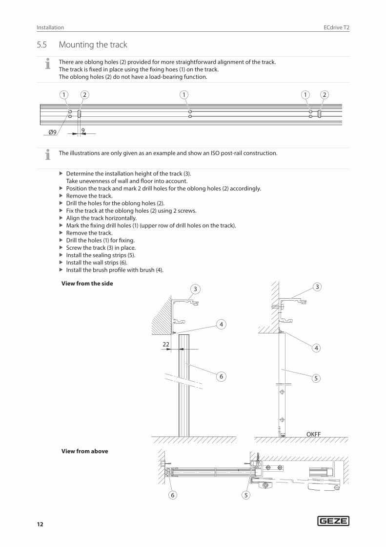
5.5 Mounting the track
There are oblong holes (2) provided for more straightforward alignment of the track. The track is fixed in place using the fixing hoes (1) on the track. The oblong holes (2) do not have a load-bearing function.
�� � � �
�� �
The illustrations are only given as an example and show an ISO post-rail construction.
X Determine the installation height of the track (3). Take unevenness of wall and floor into account.
X Position the track and mark 2 drill holes for the oblong holes (2) accordingly. X Remove the track. X Drill the holes for the oblong holes (2). X Fix the track at the oblong holes (2) using 2 screws. X Align the track horizontally. X Mark the fixing drill holes (1) (upper row of drill holes on the track). X Remove the track. X Drill the holes (1) for fixing. X Screw the track (3) in place. X Install the sealing strips (5). X Install the wall strips (6). X Install the brush profile with brush (4).
View from the side
��
����
�
�
�
�
�
�
View from above
� �

ECdrive T2
13
Installation
5.6 Installing the angled floor guide
à See the installation instructions “Continuous floor guide” (70723-9-0988) on how to install the continuous floor guide.
à For further information see the respective installation drawing, Chapter 4.1.
X Screw the angled floor guide (2) tight using 3 countersunk screws DIN 7991 M5×12 (1) (torque 6 Nm).
�
�
5.7 Fitting the door leaves
5.7.1 Mount the single roller carriage on the door leaf
X Screw the roller carriage (1) onto the door leaf.
�
�
X Position the single roller carriage in the suspension profile and fix in place.
à See the leaf installation drawing for the position of the support bracket.
y x

ECdrive T2
14
Installation
5.7.2 Fitting the door leaf with single roller carriage
Setting up door leaves
WARNING!Danger of injury caused by door leaves falling overThe door leaves are very heavy.
X At least 2 people should work together to set up the door leaves.
Aligning the door leaves
WARNING!Danger of injury caused by crushing!The door leaves are still unsecured and move easily.
X Make sure that the door leaves are not moved accidentally or by unauthorised persons.
X Clean track
X Insert roller with roller holder into the track and secure to the support bracket.
X Adjust the height of the door leaf with the screw (1). X Tighten screws (2) after adjusting the door leaf
(torque 20 Nm). X Mount the fastening bolt and adjust height.
Gap between bolt and track = 0.5 mm (corresponds to about 4 sheets of copy paper).

ECdrive T2
15
Installation
There are markings (2) on the support brackets (1) to make it easier to align the roller carriage on the door leaf. This means all roller carriages can be set the same without measurement.
�
�
Screwing driver onto roller carriage
Drivers must not touch any obstacle over the entire movement path.
X Push driver without tensioning strap (belt lock) over holes in the roller carriage and secure with 2 screws (1). Do not tighten the screws yet.
X To adjust the main closing edge, slide the driver in the oblong holes.
X Tighten screws (1). X Slide the door to the desired opening width. X Position and secure stop buffers.
1
5.7.3 Mount the support bracket for the double roller carriage on the leaf.
X Unscrew the screw (1) off the bracket (2).
The clearance a between the screw head (1) and the screw holder (3) must be set again later.
�
��
�
X Unscrew the 2 screws (3) off and remove the support bracket from the double roller carriage.
�

ECdrive T2
16
Installation
X Screw the support bracket (5) on the left and right of the door leaf (6) (torque 15 Nm).
�
�
See the leaf installation drawing for the position of the support bracket.
5.7.4 Fitting the door leaf with double roller carriage
Fixing the double roller carriage to the track
X Fit the screw (1) with screw holder (3) again.
������
�
�
X Place the double roller carriage (3) on the track (4). X Undo the screw (2) for anti-tilt roller. X Push the screw (2) upwards until the roller (5) is in
contact with the track at the top. X Tighten the screw (2).
�
�
�
�
�

ECdrive T2
17
Installation
Setting up door leaves
WARNING!Danger of injury caused by door leaves falling overThe door leaves are very heavy.
X At least 2 people should work together to set up the door leaves.
X Set up the door leaf with support bracket on double roller carriage.
Tightening the door leaves
X Screw both support brackets (3) of the door leaves to the double roller carriage (1) using safety screws Verbus-Rib M8×10 (2).
X Tighten the safety screws (2).
�
�
�
X Screw the screw (5) out of the holder (4).
Make sure that the holder (4) does not fall to the ground.
X Screw the screw (5) with screw holder (6) as far into the holder (4) as necessary until the screw (5) is in contact with the support bracket (3).
X A clearance of 6.5 mm must be kept between the holder (4) and the screw holder (6). ������
�
�
�
�

ECdrive T2
18
Installation
Aligning the door leaves
X Align door leaves flush with each other. Ensure the same height and parallel closing edges when doing so.
X Set the height and parallel position of the door leaves at the hexagon of the suspension bolt (4).
X Tighten the safety screws Verbus-Rib M8×10 (2) (torque 24 Nm).
�
�

ECdrive T2
19
Installation
Mounting the driver on the double roller carriage
X Mount the driver (2) on the double roller car-riage using 2 safety screws Inbus-Rib M6×10 (1) (torque 10 Nm).
Example: ISO leaf �
�
5.8 Mounting the drive components
If the side panels and stop buffers have not been mounted yet: X Mount the side panels and the stop buffers and fix them in place.
5.8.1 Mounting the module carriers on the left and right
WARNING!Unsecured components may fall when under load.
X When mounting the module carrier, make sure that its entire length is suspended in the track (2).
�
��
X Position the right module carrier (3) in such a way that driver does not collide with the motor. X Position the left module carrier (1) in such a way that driver does not collide with the locking mechanism or
the return pulley.
X Screw the pre-mounted module carriers left (1) and right (3) to the track (2) (torque 3.5 Nm).

ECdrive T2
20
Installation
5.8.2 Drive drawings
2-leaf
1-leaf, right hand slide to open
1-leaf, left hand slide to open
Legend:
ÖW Opening width UPL Position buffer leftUx Position module carrier left UPR Position buffer rightUy Position module carrier right

ECdrive T2
21
Installation
5.8.3 Dimensions in the drive drawings (ISO and ESG (toughened safety glass) profile system and wooden leaves)
2-leaf
Drive type Opening width Ux Uy UPL (one roller)
UPL (double roller)
UPR (one roller)
UPR (double roller)≥ <
EC T2 900 1000 70 ÖW-13.5 29–88 2–68 0–59 2–68
1000 3000 ÖW/2-400 1.5ÖW-513.5 29–38 2–18 0–9 2–18
T2-FR 900 1070 105 ÖW+21.5 29–123 2–103 0–94 2–103
T2-FR-DUO 1070 3000 ÖW/2-400 1.5ÖW-513.5 29–38 2–18 0–9 2–18
T2-FR-RWS 900 1170 155 ÖW+71.5 29–173 2–153 0–144 2–153
T2-FR-LL 1170 3000 ÖW/2-400 1.5ÖW-513.5 29–38 2–18 0–9 2–18
1-leaf, right hand slide to open
Drive type Opening width Ux UyUPL (one roller)
UPL (double roller)
UPR (one roller)
UPR (double roller)≥ <
EC T2 700 3000
35 ÖW-283.5 36–52 5–9
13–21 1–9
T2-FR 700 800 13–126 1–114
T2-FR-DUO 800 3000 13–21 1–9
T2-FR-RWS 700 860 13–181 1–169
T2-FR-LL 860 3000 13–21 1–9
1-leaf, left hand slide to open
Drive type Opening width Ux Uy UPL (one roller)
UPL (double roller)
UPR (one roller)
UPR (double roller)≥ <
EC T2 700 3000
35 ÖW-283.5
100–107 26–39
7–21 5
T2-FR 700 800 100–212 26–144
T2-FR-DUO 800 3000 100–107 26–39
T2-FR-RWS 700 860 100–267 26–199
T2-FR-LL 860 3000 100–107 26–39
à The drive drawings are subject to change. Use only the most recent version. à For GC profiles Therm: Use the information from the drive drawings.

ECdrive T2
22
Installation
5.8.4 Mounting the toothed belt
X Thread the toothed belt on the motor pulley and return pulley, shorten if necessary.
X Insert toothed belt ends (1) into the toothed belt lock (2) (3 teeth per side).
1
2
1
X Mount the toothed belt lock (2) with screws (4) on the short driver (3).
X Do not tighten the screws yet.
��
�
5.8.5 Tensioning the toothed belt
X The toothed belt must be pre-tensioned with 300 N ±35 N (see drive drawing).
X Undo 2 screws (2). X Push the motor (3) to the right by hand. X Undo the screw (1) and move the sliding block
in such a way that a screwdriver can be pushed between the sliding block and the motor.
X Tighten the screw (1) (torque 10 Nm). X Push the screwdriver into the gap and lever it
until the toothed belt is tensioned. X Tighten 2 screws (2) (torque 15 Nm).
12
3

ECdrive T2
23
Installation
5.8.6 Setting the closing position for 2-leaf systems
X Push the door leaf to the closed position. X Fit second belt lock, do not tighten the screws (2) yet. X Use the oblong holes (1) to finely adjust the position in the direction of displacement. X Tighten the screws (2) when the exact closing position has been set (torque 6 Nm).
5.8.7 Connecting the left and right module carriers to the power supply
X Connect the transformer cable (1) to the control unit.
X Fix the cable holder (1) to the module carrier. X Fix the cable holder (3) to the control unit. X Route the transformer cable (2) through the
cable holders to the control unit.1
�
��

ECdrive T2
24
Installation
5.8.8 Connecting the toothed belt locking (optional) and control unit
1 2
3
X When fitting the cover (3) make sure that no cables become jammed.
X Plug the cable toothed belt locking (optional) (1) in at the control unit (2). X Route cable to the toothed belt locking (optional), shorten if necessary, strip and attach the insulated wire-
end ferrules. X Connect the cable to the toothed belt locking (optional) (1) (see wiring diagram). X Connect further components if appropriate. X Place cover (3) on control unit and lock in place. The retention force of the cover can be increased by slightly
bending the cover.

ECdrive T2
25
Installation
5.8.9 Mounting the transformer earthing
� �
X Screw the device flat plug (1) to the track using the slotted pan head screw 3.5 ×16 (2) (torque 3.5 Nm).
X Connect the earthing cable (3) from the trans-former to the device flat plug.
�

ECdrive T2
26
Production test and commissioning
6 Production test and commissioning X Carry out the production test as described in the wiring diagram “Automatic sliding doors DCU1-NT/DCU1-2M-NT”.
6.1 Connecting the drive
WARNING Risk of fatal injury due to electric shock!
X The electrical system (230 V) may only be connected and disconnected by a professional electrician. X Carry out mains connection and earth conductor test in accordance with VDE 0100 Part 610.
X Insert the battery connector (1) at the control unit.
1
During maintenance work, the battery must be disconnected from the control unit!
X Check whether the battery cable is long enough, attach extension cable if necessary. X Connect drive to 230 V mains (230 VAC ±10%, 50/60 Hz) and switch on the main switch on the transformer.
6.2 Connecting cover earthing
� �
�
�
�
X Connect the earthing cable (2) of the cover with the second plug-in connection of the device flat plug (1).
Depending on the length of the drive, a 2nd device flat plug with earthing cable must be mounted to bridge the distance between the transformer earthing and the cover earthing.
X Push the cable lug of the earthing cable for the cover (2) onto earthing (3). X Secure with hexagon nut (4).

ECdrive T2
27
Production test and commissioning
6.3 Mounting the cover securing device
CAUTION! Danger of injury!People can be injured when the cover is pivoted.
X Always make sure two people handle the cover.
CAUTION! Danger of injury from falling cover!
X Make sure that the cover has latched in securely at the side panels. X Release the cover carefully and check whether it has been suspended safely.
X Unscrew the red locking pin (1) from the toothed belt locking (optional) before mounting.
6.3.1 Drill a hole for the toothed belt locking (optional).
The position of the hole must be checked. Depending on the positioning of the drive components, minor devia-tions can occur here.
Dimensional specifications for dimension C can be found in the component drawing for the cover (70518-2-0203).
X Drill a hole Ø 20 mm. X Deburr the hole. ����
����
�
����
6.3.2 Mounting the cover fixingTo guarantee the stability of the cover, cover fixings must be mounted to the track.The number and installation position depends on the length of the drive.
Length of drive Number of cover fixingsup to 4000 mm 24001 mm–5000 mm 35001 mm–6000 mm 5
Installation position
Drive length up to 4000 mm:
��� ���
��� ���
��� ���
� �
����
Drive length 4001–5000 mm:
Drive length 5001–6000 mm:

ECdrive T2
28
Production test and commissioning
Inserting cover fixing
��
� �
�
X Set the cover fixing (1) onto the track (3). X Secure the cover fixing (1) using a screw (2).
Mounting the cover securing device
� � ��
�
X Hook the cover safety rope (4) in the cover suspension piece (5) in the cover. X Hook the cover safety rope (4) in the suspension piece (3) of the side panels. X Slide the cover onto the side panels until it latches in and ensure that it is also seated correctly in the area of
the module carriers and cable holders.
X Check the correct position of the cover safety ropes (4) and the earthing wire. There must not be any contact with moving parts.
X Position the rotating pin (2) in the locking device. X Secure the rotating pin (2) using a screw (1).
X After mounting, the grey rotating pin (2) must be positioned above the hole in the cover so that it can be locked and unlocked.
X If necessary, enlarge the drill hole in the cover.
6.3.3 Mounting the safety equipment X Mount safety and activation equipment. X Route cables properly in cable ducts.
For electrical installation, see wiring diagram.
6.3.4 Installing switches/push buttonsFor electrical installation, see wiring diagram.
6.3.5 Installing programme switchFor electrical installation, see wiring diagram.

ECdrive T2
29
Service and maintenance
6.4 Commissioning the door system
For information about connection and parameter setting of the safety sensors, and the inputs and outputs and on commissioning, please refer to the wiring diagram.
6.4.1 Creating test log X Carry out a safety analysis. X Record installed options in the safety analysis for the owner.
6.5 Dismantling
WARNING! Risk of fatal injury due to electric shock!
X The electrical system (230 V) may only be connected and disconnected by a professional electrician. X Carry out mains connection and earth conductor test in accordance with VDE 0100 Part 610.
CAUTION! Danger of injury!People can be injured when the cover is pivoted.
X If the cover is more than 4 m long, always work in pairs when handling the cover.
CAUTION! Danger of injury due to impact and crushing!
X Secure the door leaves against unintentional movement. X Disconnect the rechargeable battery.
Dismantling is done in the reverse order of installation.
7 Service and maintenance
7.1 Mechanical service
7.1.1 Checking toothed belt tension X Put the door into operation.
The toothed belt must not lift up from the motor gear or skip when braking and accelerating. X If the toothed belt lifts up or skips, increase the toothed belt tension:
à Mark motor position on the track. à Move motor to the right in 1 mm increments.
7.1.2 Tensioning the toothed beltSee Chapter 5.8.5.

ECdrive T2
30
Service and maintenance
7.2 Maintenance
The prescribed maintenance work on the ECdrive T2 and ECdrive T2-FR must be done by an expert: à at least once a year
or à when the service indicator on the programme switch lights up (see wiring diagram)
X Provide test documents and keep them up-to-date.
After completing the maintenance work, always execute the learning function for the door.
Test spot Action Comments
Track Check for cracks X Replace the track
Check for cleanliness X Clean the track
Roller carriage Check the abrasion of the rollers X Remove the abrasion
Check brushes X Remove the roller carriage (see Chapter 9.1.2 “Replacing roller on single roller car-riage” or Chapter 9.1.4 “Replacing rollers on double roller carriage”)
X Replace the brushes (see Chapter 8.1.2 “Replacing roller on single roller carriage” or Chapter 8.1.3 “Replacing rollers on double roller carriage”)
Floor guide area Check for jarring-free function X Clean floor guide area
Floor guide area (brushes) Check for soiling and hardness X Clean or replace
Door leaf Check for smooth movement X See Chapter 8.1.1
Toothed belt Check for wear & tear and damage X Replace the toothed belt
Check tension X Tension toothed belt (see Chapter 5.8.5)
Check the toothed belt locking (optional) for damage
X Replace the toothed belt
Toothed-belt locking (optional)
Check function X Reposition the toothed belt locking (op-tional) (see Chapter 6.3)
Screws Check for tight fit X Tighten the screws if (refer to drive draw-ing for torques)
Assembly groups and peripherals
Check for correct function X Replace assembly group
Cables Check for damage and correct fastening X Fasten or replace cables

ECdrive T2
31
Troubleshooting
8 Troubleshooting
WARNING!Risk of fatal injury due to electric shock!
X The electrical system (230 V/115 V) may only be connected and disconnected by a professional electrician. X Carry out mains connection and earth conductor test in accordance with VDE 0100 Part 610.
CAUTION!Danger of injury with opened drive!Hair, clothing, cables, etc. can be drawn in by rotating parts.
X When working on the opened drive, watch out for rotating parts!
CAUTION! Danger of injury due to impact and crushing!
X Secure door leaves against accidental movement. X Disconnect battery.
8.1 Mechanical faultsCause RemedyTrack bent X Replace track.
X Check the installation surface.Door leaf is stiff X Check the door leaf (see below). Roller carriage jammed or defective, high abrasion on the rollers
X Check toothed belt at driver for perpendicular fit. X Guide toothed belts so that they are parallel. X Replace the roller carriage (see below).
Toothed belt damaged X Replace the toothed belt.Assembly group defective X Replace the assembly group (see below).
8.1.1 Checking the door leaves X Disconnect the moving leaf from the toothed belt using the driver. X Move door leaves and check for ease of movement.
If door leaves move easily: X Check the drive motor and replace it if necessary.

ECdrive T2
32
Troubleshooting
8.1.2 Replacing brushes on single roller carriage
X Secure door leaves against falling. X Remove roller carriage. X Pull brush (3) out of support bracket (1). X Clean roller (2) and insert new brush. X Reinstall roller carriage in reverse order.
�
�
�
8.1.3 Replacing brushes on double roller carriage
X Secure door leaves against falling. X Remove the door leaf and tilt it as described
in Chapter 9.1.4. X Pull brushes (1) out of roller bracket (3). X Clean rollers (2) and insert new brushes. X Hook door leaf in again and adjust it. X Set safety roller.
�
�
�
��

ECdrive T2
33
Troubleshooting
8.2 Electrical faults X For read-out instructions and a list of fault messages, see wiring diagram.
8.2.1 Replacing fuse in transformer
DANGER! Risk of fatal injury due to electric shock! If the main switch on the transformer is activated, the fuse is still energised since it is upstream of the main switch.The mains voltage 230 V must be disconnected from the mains upstream of the fuse.
X Disconnect the system from the 230 V mains supply on site before removing the PCB cover (1) and secure against being switched back on again.
X You will find the fuse value on the wiring diagram.
1111
X Insert a suitable screwdriver into the opening of the PCB cover (1) above the switch. X Carefully press the end wall of the PCB cover upward with the tip of the screwdriver.
This releases the snap catch. X Remove the PCB cover (1). X Pull the fuse holder forwards and off and replace the defective fuse. X Attach the fuse holder.
X Do not trap the cable when setting the cover in place.
X Set the PCB cover (1) in place and clip on.

ECdrive T2
34
Inspection of the installed system
9 Inspection of the installed system
9.1 Measures for protection and prevention of pinching, impact, shearing or drawing-in spots:
X Check the function of safety sensors and movement detectors. X Check protective earth connection to all metal parts that can be touched. X Perform a safety analysis (risk analysis).
9.2 Mounting checklist ECdrive T2No. Test In chapter On page Com-
pleted1 All cables routed correctly for installation of the ECdrive T2? 5.2 102 Track mounted? 5.5 123 Angled floor guide/continuous floor guide installed? 5.4 114 Door leaf with single roller carriage installed? 5.7.2 145 Door leaf with double roller carriage installed? 5.7.4 166 Drive components installed? 5.8 197 Toothed belt mounted? 5.8.4 228 Closing position for 2-leaf system set? 5.8.6 239 Left and right module carriers connected to the power supply? 5.8.7 2310 Toothed belt locking (optional) and control unit connected? 5.8.8 2411 Safety equipment mounted? 6.3.3 2812 Switches/push buttons installed? 6.3.4 2813 Programme switch installed? 6.3.5 2814 Transformer earthing mounted? 5.8.9 2515 230-V connection established? 6.1 2616 Cover earthing connected? 6.2 2617 Cover fixing mounted? 6.3.2 2718 Cover securing device mounted? 6.3.2 2719 Safety equipment mounted? 6.3.3 2820 Additional switches and push buttons mounted? 6.3.4 2821 Programme switch installed? 6.3.5 2822 Safety analysis carried out? – –23 Deviations of the system checked in accordance with safety analysis? – –24 à Safety clearances correct? – –25 à Detection area radar detector in the direction of emergency exit set
properly?– –
26 à Photoelectric barriers for main closing edge set correctly? – –27 à Programme switch for FR systems secured through key switch? – –28 Are all components mounted in accordance with the following instruc-
tions:– –
29 à Pre-installation instructions ECdrive T2 – –30 à Installation instructions ECdrive T2 – girder section and side panel – –31 à Pre-installation and installation instructions GCprofile Therm - fan-
light– –
32 à Pre-installation instructions profile system leaves and side panel – –

ECdrive T2
35

GermanyGEZE GmbHNiederlassung Süd-WestTel. +49 (0) 7152 203 594E-Mail: [email protected]
GEZE GmbHNiederlassung Süd-OstTel. +49 (0) 7152 203 6440E-Mail: [email protected]
GEZE GmbHNiederlassung OstTel. +49 (0) 7152 203 6840E-Mail: [email protected]
GEZE GmbHNiederlassung Mitte/LuxemburgTel. +49 (0) 7152 203 6888E-Mail: [email protected]
GEZE GmbHNiederlassung WestTel. +49 (0) 7152 203 6770 E-Mail: [email protected]
GEZE GmbHNiederlassung NordTel. +49 (0) 7152 203 6600E-Mail: [email protected]
GEZE Service GmbHTel. +49 (0) 1802 923392E-Mail: [email protected]
AustriaGEZE AustriaE-Mail: [email protected]
Baltic StatesGEZE GmbH Baltic States officeE-Mail: [email protected]
BeneluxGEZE Benelux B.V.E-Mail: [email protected]
BulgariaGEZE Bulgaria - Trade E-Mail: [email protected]
ChinaGEZE Industries (Tianjin) Co., Ltd.E-Mail: [email protected]
GEZE Industries (Tianjin) Co., Ltd.Branch Office ShanghaiE-Mail: [email protected]
GEZE Industries (Tianjin) Co., Ltd.Branch Office GuangzhouE-Mail: [email protected]
GEZE Industries (Tianjin) Co., Ltd.Branch Office BeijingE-Mail: [email protected]
FranceGEZE France S.A.R.L.E-Mail: [email protected]
HungaryGEZE Hungary Kft.E-Mail: [email protected]
IberiaGEZE Iberia S.R.L.E-Mail: [email protected]
IndiaGEZE India Private Ltd.E-Mail: [email protected]
ItalyGEZE Italia S.r.lE-Mail: [email protected]
GEZE Engineering Roma S.r.lE-Mail: [email protected]
PolandGEZE Polska Sp.z o.o.E-Mail: [email protected]
RomaniaGEZE Romania S.R.L.E-Mail: [email protected]
RussiaOOO GEZE RUSE-Mail: [email protected]
Scandinavia – SwedenGEZE Scandinavia ABE-Mail: [email protected]
Scandinavia – NorwayGEZE Scandinavia AB avd. NorgeE-Mail: [email protected]
Scandinavia – DenmarkGEZE DanmarkE-Mail: [email protected]
SingaporeGEZE (Asia Pacific) Pte, Ltd.E-Mail: [email protected]
South AfricaGEZE South Africa (Pty) Ltd.E-Mail: [email protected]
SwitzerlandGEZE Schweiz AGE-Mail: [email protected]
TurkeyGEZE Kapı ve Pencere SistemleriE-Mail: [email protected]
UkraineLLC GEZE UkraineE-Mail: [email protected]
United Arab Emirates/GCCGEZE Middle EastE-Mail: [email protected]
United KingdomGEZE UK Ltd.E-Mail: [email protected]
GEZE GmbHReinhold-Vöster-Straße 21–2971229 LeonbergGermany
Tel.: 0049 7152 203 0Fax.: 0049 7152 203 310www.geze.com