Embed Size (px)
Citation preview

Installation Guide
Eaton Hydraulic Launch Assist (HLA)TRIG1200 EN-USJune 2012


i
Table of ContentsTable of Contents
Warnings and Cautions . . . . . . . . . . . . . . . . . 1
General Information How to Use this Guide . . . . . . . . . . . . 3 Hydraulic Hybrid Overview . . . . . . . . . 3 Major Subsystems and Components . 3 Typical Installation and Configuration . 5
Installation Summary Component Installation . . . . . . . . . . . . 7Communications . . . . . . . . . . . . . . . . . 8Commissioning . . . . . . . . . . . . . . . . . . 8Special Tools . . . . . . . . . . . . . . . . . . . . 8
Installation Requirements Chassis Requirements . . . . . . . . . . . . 9 Engine Controller . . . . . . . . . . . . . . 9 Driveline. . . . . . . . . . . . . . . . . . . . . 9 Break Pressure Sensor. . . . . . . . . . 10 Anti-Lock Breaking System (ABS) . 10 Pneumatic Supply . . . . . . . . . . . . . 10 Component Installation . . . . . . . . . 10 HLA System Requirements . . . . . . . . . 11
Pump/Motor and Transfer Case(PMTC) Subsystem . . . . . . . . . . . . 11Accumulator and Reservoir Lifting Requirements . . . . . . . . . . 14
Reservoir Subsystem . . . . . . . . . . 17 Breather Installation and Use
Instructions . . . . . . . . . . . . . . . . . . 17 Reservoir Installation . . . . . . . . . . 19 Accumulator Subsystem . . . . . . . . 20 Accumulator Installation . . . . . . . . 22 Cooler Subsystem . . . . . . . . . . . . . 23 Cooler Installation . . . . . . . . . . . . . 24 Hose Subsystem . . . . . . . . . . . . . . 25 Hose Definitions . . . . . . . . . . . . . . 26
Electrical Requirements Chassis Requirements . . . . . . . . . . . . . 35 Ignition Line Voltage . . . . . . . . . . . 35 Interface Wiring . . . . . . . . . . . . . . . 36 HLA® ECU Connector . . . . . . . . . . 36 HLA® Cooler Interface Connector . 37 Power Requirements . . . . . . . . . . . 38 Harness Routing Requirements . . . 39 Harness Design Recommendations 39
Data Link Requirements . . . . . . . . . . . . 41 Messages . . . . . . . . . . . . . . . . . . . . 41 In-Cab Display . . . . . . . . . . . . . . . . 42
HLA® System Harness Connection . . . 43 Reservoir Connections . . . . . . . . . . 44 Accumulator and Cooler
Connections . . . . . . . . . . . . . . . . . . 45 Chassis Harness Connection to
HLA® System . . . . . . . . . . . . . . . . . . . 46 In-Cab Display . . . . . . . . . . . . . . . . 47
eVU . . . . . . . . . . . . . . . . . . . . . . . . 48
End Of Line (EOL) Inspection Commissioning Procedure . . . . . . . . . . 51
Pre-commission Inspection . . . . . . 51 Oil Fill Procedure. . . . . . . . . . . . . . . 51 System Air Purge . . . . . . . . . . . . . . 52 Necessary Hardware . . . . . . . . . . . . 52
Pre-Delivery Inspection (PDI) . . . . . . . . . . . . . 53 Real Time Warranty Pre-Call Checklist. . 54
Installer Capabilities . . . . . . . . . . . . . . . . . . . 55
Material Handling . . . . . . . . . . . . . . . . . . . . . . 57


Warnings and CautionsW
arnings and Cautions
Warnings and Cautions
The description and specifications contained in this service publication are current at the time of printing.
Eaton Corporation reserves the right to discontinue or modify its models and/or procedures and to change specifications at any time without notice.
Any reference to brand name in this publication is made as an example of the types of tools and materials recommended for use and should not be considered an endorsement. Equivalents may be used.
Warning indicates you will be severely Injured or Killed if you do not follow the indicated procedure.
Caution indicates an Immediate Hazard, which could result in Severe Personal Injury if you do not follow the indicated pro-cedure.
Important indicates Vehicle or Property Damage could occur if you do not follow the indicated procedure.
Note: Note indicates additional detail that will aid in the service or repair of component or system.
HLA® system will not stop vehicle. Driver must be prepared to apply brakes anytime the HLA® system is in regenerative braking.
Before doing maintenance: Shut off the engine. Chock the wheels. Set the parking brake.
Oil level must stabilize before reading the volume. Improper oil level will result in damage to HLA® system components. When the vehicle is turned off, the oil in the accumulator will drain back to the reservoir. This process takes approximately ten seconds. When the oil level has stabilized, read the oil level through the sight glass. Fill to the top of the sight glass.
Use only HLA® system approved Hydraulic Fluid – 5W-20 OS245652 in the HLA® system. Other fluids may damage compo-nents or reduce performance.
Use only full synthetic 75W-90 per full efficient axle fluid spec SHAES 256 Rev C in the Transfer Case. Damage may result with other fluids.
Do not use liquid nitrogen, oxygen or compressed shop air to charge accumulator.
Failure to properly install the thermal relief fuse cap could result in an accumulator burst event if the accumulator becomes overheated.
Avoid suffocation. Nitrogen asphyxiates. Move to ventilated area upon opening the vent. See MSDS for more information on nitrogen gas.
WARNING
CAUTION
IMPORTANT
WARNING
1
Warnings and Cautions
Improper nitrogen gas pressure will result in reduced HLA® system performance.
Add nitrogen slowly for first 7 bar (100 psi) to new or rebuilt accumulator. Do not exceed 2 bar (30 psi) per minute. Bladder damage may result if rapidly inflated.
No other vehicle components may be in contact with the HLA® system. The HLA® system may not be used to support other vehicle components.
Escaping nitrogen gas is extremely cold and may freeze skin. Avoid skin contact with the nitrogen gas to prevent freezing damage to skin tissues.
For proper operation, use only dry industrial grade nitrogen to charge accumulator.
CAUTION
IMPORTANT
2

General InformationGeneral
Information
General Information
How to Use this Guide
This Eaton publication is intended to be a reference guide for the installation of the HLA® system. This information benefits the installer by providing the correct installation requirements and procedures to ensure the utmost in satisfactory operation and long service life. For additional information, see the Suggested Tools section.
Attention: Risk of voiding warranty.
This Installation Guide provides installation procedures, requirements, and recommendations which are collectively required and necessary for the proper functioning of Eaton HLA® Systems. Failure to follow these procedures, recommendations, and requirements will void the warranty in certain cases. Please contact your Eaton representative before taking any action departing from this Installation Guide.
The HLA® system is compatible with electronically governed engines equipped with an SAE J1939 data link and certified by Eaton Corporation. Installed HLA® systems must meet the requirements in this guide and be approved by Eaton Application Engineering Team. Contact Eaton Application Engineering Team or the installer's Application Engineering department for the proper application form. All applications must be submitted for approval.
Hydraulic Hybrid Overview
The Hydraulic Launch Assist (HLA®) is a hybrid system designed to increase fuel economy and increase vehicle brake life in vehicles with heavy start-stop drive cycles. The system does this by capturing energy during braking and then reusing the energy to launch the vehicle. HLA® is a parallel system which means the vehicle can operate like a non-hybrid vehicle if the HLA® shuts down. Another benefit of the parallel architecture is both the engine and the HLA® system can turn the drive axle (together or independently). The HLA® system is an addition to existing drivelines and does not replace the conventional vehicle transmis-sion.
Major Subsystems and Components
The HLA® system consists of five major subsystems, each with numerous subcomponents. The subsystems and major sub-components are listed below. The list is for reference only and should not be mistaken for a complete bill of materials.
Pump/Motor and Transfer Case Subsystem
• Pump/Motor Assembly
• Transfer Case Assembly
• Mounting Brackets
• ECU Enclosure
• HLA® Wire Harness
Accumulator Subsystem
• Accumulator
• Mounting Clamps
WARNING
3

General Information
Reservoir Subsystem
• Reservoir
• Filter
• Breather
Cooler Subsystem
• Cooler
• Mounting Brackets
• Cooler Subassembly Wire Harness
Hose Subsystem
• Filter Block Subassembly
• Suction Hose Subassembly
• Cooler Inlet Hose Subassembly
• Cooler Outlet Hose Subassembly
• Case Drain Hose Subassembly
• Low Pressure Hose Subassembly
• High Pressure Hose Subassembly
The following table illustrates the approximate subsystem weights.
It is recommended that the installation be conducted in the following order:
1. Install all hardware components to the chassis. It is to the installer's discretion to determine the order of hardware installation (front to rear, inside to outside, etc.).
2. Install all hose subassemblies.
3. Make wire harness connections.
Subsystems Approximate Weight (lbs)
Pump/Motor Transfer Case 942
Accumulator 382
Reservoir 176
Hose 104
Cooler 60
4

General InformationGeneral
Information
Typical Installation and Configuration
Transfer Case
Pump/Motor
Reservoir
Accumulator
Cooler
Filter
ECU
Point of UseFilter
Sight Level Gauge
Gas Port
5

General Information
6

Installation SummaryInstallation Sum
mary
Installation Summary
The following is a brief summary of items required on the host chassis that are to be provided by the installer. Details are pro-vided throughout the document on each item in the list.
Component Installation1. Installation holes, mounting brackets, mounting hardware, and torque specifications to secure Pump/Motor and Trans-
fer Case (PMTC) to chassis
2. Installation holes, mounting brackets, mounting hardware, and torque specifications to secure Accumulator to chassis
3. Installation holes, mounting hardware, and torque specifications to secure Cooler to chassis
4. Installation holes, mounting hardware and torque specifications to secure Reservoir to chassis
5. Input and output driveshafts
6. Pneumatic supply to the Pump/Motor and Transfer Case (PMTC)
7. Design and installation of the electrical harness from the chassis to HLA
8. Design and installation of the electrical harness to the in-cab display
9. Selection and installation of an in-cab display
10. Selection and installation of a brake pressure sensor
11. Selection and installation of an isolation mount
12. Installation of the HLA harness to the HLA components
13. Installation of the HLA fluid into the system
14. Installation of the Transfer Case fluid into the Transfer Case
Part Name Manufacturer Part Number Quantity Required
eVU Driver Display Eaton/Cutler Hammer e00FP0001 1
eVU Driver Display – connector Eaton/Cutler Hammer 25-24787 1
eVU Driver Display – terminal Tyco Electronics/AMP 927771-1 5
Brake pressure transducer Sensata Technologies Bendix: 5005758TI: 6CP3-1
1
Isolation mounts Lord CB-1122-2 4
HLA fluid Cognis 5003593 (drum)5003856 (tote)
21 gallons/system
Transfer case fluid Cognis Roadranger FE 75-W90 or equivalent
7.25 quarts/system
Accumulator brackets 3
Pump/Motor brackets 2 or 4 (depending on design)
Retrofit harness Eaton 6025884-001 1 (optional)
7

Installation Summary
Communications1. The engine controller must accept speed and torque limit requests per SAE J1939-71.
2. The chassis must have an ABS system and the ABS system must be SAE J1939-71 compliant.
3. The driver display must be able to receive the in-cab display message and display the signal information described in the Data Link Requirements section.
Commissioning
Run the purge process using the ServiceRanger tool on each vehicle.
Special ToolsPart Name Manufacturer Part Number Quantity Required
Transfer pump filter cart(3 micron elements with 1000 beta ratio)
Eaton CC0FRS60 055003889
1
Quick disconnect Aeroquip 5608-8-10S 1
ServiceRanger software for commissioning/troubleshooting (PC based)
Eaton Version 3.2 or later 1
Nexiq USB link and vehicle interface adapter Nexiq 125032 1
Nitrogen charging kit Eaton 100AV00093A 1
8
Installation RequirementsInstallation
Requirements
Installation Requirements
Chassis Requirements
Engine Controller
The engine controller must accept speed and torque limit requests from source address 239: PGN 0 per SAE J1939-71. See Data Link Requirements section for details.
Driveline
The driveline is the responsibility of the installer. There is a recommended minimum driveline length of 92 inches, as measured from the transmission output yoke to the drive axle input yoke, in order to install the HLA® system. The HLA® is supplied with a Spicer 1810 series driveline full-round yoke on the rear (axle side) and the option of an 1810 full-round or 1760 half-round yoke on the front (transmission side). Contact Eaton Application Engineering Team for additional driveline configuration requests. The installer is responsible for placement of the HLA® system such that the driveline angles are acceptable. The input and output of mechanical power is accomplished via the host vehicle driveline. The following table illustrates the additional torque the HLA® system imparts on the lower power train.
The following figure illustrates a typical installation, where the front of the vehicle is located to the right of the figure.
Requirement Max. Unit Notes
HLA® retarding torque 2750 ft-lb 1
HLA® accelerating torque 2550 ft-lb 2
Notes1 – The vehicle driveline (from rear wheels to HLA® system) must be capable of handling the retarding torque generated by the HLA® system plus upper power train (engine + transmission) retarding torque. 2 – The vehicle driveline must be capable of handling drive torque provided by the upper power train plus the assist torque provided by the HLA® system.
9

Installation Requirements
Brake Pressure Sensor
In order for the HLA® system to function properly, it must know the amount of braking effort being input from the driver. The HLA® requires the installation of a brake pressure sensor by the installer. This sensor will measure the brake system pressure that is being applied to the brakes. The wiring for this sensor is included in the electrical requirements section. The installer shall provide the brake pressure sensor and the associated wiring between the sensor and the chassis-to-HLA® connector. The brake pressure sensor shall meet the following requirements. It is the installer's responsibility to provide any additional wiring and the mating connector for the sensor.
• Power Supply Voltage: 4.75 / 5.25 VDC
• Supply Current: 12 mA Max
• Operating Temperature: -40° to 125°C
• Output Load: 51k Ohm Pull Down
• Output Signal Transfer Function:.
Where Pin is the sensor output in PSI, this translates to 0 psi reading at 0.5 volts and 150 psi at 4.5 volts
Note: A Texas Instruments / Sensata 6CP3-1 pressure sensor is recommended for this application.
Anti-Lock Braking System (ABS)
The HLA® system requires the chassis to have an Anti-Lock Braking System (ABS) and the ABS controller must be SAE J1939 compliant. The ABS must broadcast PGN 61441 per SAE J1939-71. See Data Link Requirements section for details.
Pneumatic Supply
The HLA® system requires a connection to the truck air supply. The air supply is used to activate a pneumatic valve on the trans-fer case clutch. The installer shall supply a connection from the chassis air supply to a pneumatic valve mounted on the transfer case. The chassis pneumatic system shall meet the following requirements:
• Pneumatic System Air Pressure: 60 psi minimum and 150 psi maximum.
• Pneumatic System Air Volume Delivery: 79 CC
• Port Fitting on Valve: ¼" Push-to-Connect (PTC)
Component Installation
The installer is responsible for ensuring proper installation of the HLA® system components to the chassis. Any necessary installation holes, as well as, bolts, nuts, and tightening torques are the responsibility of the installer. If assistance is needed, the Eaton Application Engineering Team is available to provide recommendations.
10

Installation RequirementsInstallation
Requirements
HLA® System Requirements
All screen shots shown throughout this document shall be considered as reference only. The screen shots are of a "typical" installation, but do not intend to define the only installation possible. All dimensions shown throughout this document shall be considered as reference only and are provided for the installer's benefit. Installation drawings provide the detailed dimensions of the HLA® system. Contact the Eaton Application Engineering Team for more information.
Pump/Motor and Transfer Case (PMTC) Subsystem
WARNING
11
Installation Requirements
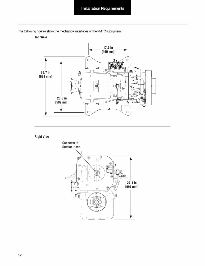
The following figures show the mechanical interfaces of the PMTC subsystem.
Top View
17.7 in[450 mm]
26.7 in
[678 mm]
23.6 in
[599 mm]
Connects to
Suction Hose
27.4 in
[697 mm]
Right View
12

Installation RequirementsInstallation
Requirements
Yoke Combination
Engine Side Rear Side "A"
1810 1810 22.84 in.
1760 1810 22.75 in.
40.0 in
[1015 mm]
A (see table)
Connects to Case
Drain Hose
Connects to High
Pressure Hose
Connects to Low
Pressure Hose
Connects to
Cooler
Front View
Oil Fill/Quick
Disconnect
13

Installation Requirements
Accumulator and Reservoir Lifting Requirements
The Pump/Motor and Transfer Case (PMTC) assembly must be oriented in the vehicle such that the transfer case is located on the transmission side of the driveline with the driveline underneath the assembly. The installer is responsible for selecting suit-able bolt, nut, and torque specifications for mounting the PMTC to the chassis. The following figure is an example of a typical installation. The installer is responsible for brackets or mounting hardware necessary to install the PMTC to the chassis. The HLA® system wire harness comes attached to the PMTC and bundled together. Do not unbundle the harness until afterinstallation.
1 Use lifting eyes to raise pump/motor above chassis frame rails.
14

Installation RequirementsInstallation
Requirements
Eaton has performed NVH analysis and recommends the installer utilize Lord CB-1122-2 isolation mounts between the PMTC mounting brackets and the chassis. These isolation mounts will help to minimize noise transmission from the HLA® system to the chassis.
Deflection A
± .03 B
± .01F
± .02 E
± .015D C
± .015 Load
lbs N in mm in mm in mm in mm in mm
YellowCB-1122-2 350 1560 .06 1.52 2.00 50.8 .532 13.5 1.35 34.3 1.62 41.1 1.31 33.3 .53 13.5
in mm in mm
IDmin. dia.
F ± .02
Grade or Class
in mm in mm English Metric SAE J249 ft lb Nm
.62 15.8 .06 1.5 2.25 57.2 2.0 50.8 1.25 31.8 1/2” M12 2 5.8 48 65
in mm in mm
T± .03
Recommended Bolt Information
R± .015
.45 11.4
H± .03
in mmin mm
KDmin. dia.
SDmin. dia.
Size
Installation Requirements
SAE J249
Maximum Axial Static Load Rating
Part Dimensions
ColorCode
Part Number
ADIA.
CDIA.
D E
FBDIA.
KD
ID
SD
H
AXIALLOAD
DIRECTION
SUPPORTEDMEMBER
SUPPORTINGMEMBER
TR
15

Installation Requirements
The transfer case uses the existing vehicle pneumatic supply to engage or disengage the transfer case. Connection of the transfer case to the vehicle pneumatics is shown in the following figure.
1 Connect OEM-supplied air line:• Push air line through
resistance into push-lock fi tting.
• Tug air line to make sure connection is secure.
ConnectOEM Air Supply
16

Installation RequirementsInstallation
Requirements
Reservoir Subsystem
While installing the reservoir, make sure the reservoir is oriented in such a way that the breather is on the top side. Ensure that the breather red pin is not visible. If red pin is visible, reset the indicator by gently tapping the base of the unit until the red pin is out of sight. Please refer to the following pictures for resetting the indicator. The installer is responsible for selecting suitable bolt, nut, and torque specifications for mounting the reservoir to the chassis.
Breather Installation and Use Instructions
Breather
This unit has a change out indicator. If red pin is visible, reset indicator by gently tapping unit base until red pin is out of sight.
Screw adapter on to threaded flange assembly on reservoir fill port.
Caution: Hand tighten only. Do not use tools.
Note: Replace water-gate when red pin is visible in top of dome or six months after installation date, whichever occurs first.
1 2
17
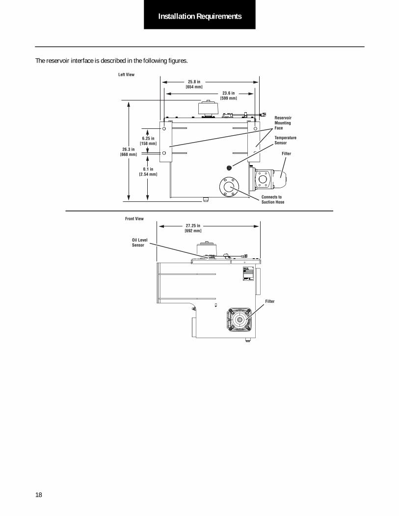
Installation Requirements
The reservoir interface is described in the following figures.
27.25 in
[692 mm]
Oil Level
Sensor
Front View
Connects to
Suction Hose
26.3 in
[668 mm] Filter
Left View
25.8 in
[654 mm]
23.6 in
[599 mm]
6.25 in
[158 mm]
0.1 in
[2.54 mm]
Temperature
Sensor
Reservoir
Mounting
Face
Filter
18

Installation RequirementsInstallation
Requirements
Reservoir Installation
DamagedClear
1 Install mounting studs:• Align and thread studs
through openings.• Torque to 60 ± 6 ft-lb.
3 Install reservoir:• Secure with
washers and nuts.• Torque to OEM
specifi cation.
4 Verify breather indicator fi lter is clear.
Note: Breather indicator may be red due to shipping damage. Contact Eaton quality representative for repair strategy.
2 Align reservoir mounting bracket with chassis frame holes.
19

Installation Requirements
Accumulator Subsystem
Please read the Material Handling section for details regarding handling pressurized accumulators.
The Accumulator shall be mounted with the clamps described in the following figures. The clamps are part of the Accumulator subsystem and will be provided by Eaton. The installer is responsible for creating the mounting brackets to secure the clamps to the chassis. The installer is responsible for selecting suitable bolt, nut, and torque specifications for mounting the accumulator to the chassis. A minimum of three clamps are required for the steel accumulator. The clamp dimensions are shown and the allow-able location of the three clamps are identified in orange. Note that the middle clamp should be placed in the center of the accu-mulator as detailed in the following figures.
The accumulator orientation during installation shall be such that the two sensors that are installed at the hydraulic end of the accumulator are in a horizontal position relative to the ground. This ensures that the sensor guard is in the correct position to provide protection to the sensors from road debris.
WARNING
20

Installation RequirementsInstallation
Requirements
Ø 9.5 in
[241 mm]
76.3 in
[1939 mm]
34.25 in
[870 mm]
24.9 in
[632 mm]
27.6 in
[700 mm]
27.6 in
[700 mm]
24.9 in
[632 mm]
Nitrogen Fill Location and
Thermal Relief Valve Proximity Sensor
Connects to HP Hose
Pressure Sensor
C
H
K
A
B
D
ØL
Z
Torque to 35 ± 3.5 Nm
(26 ± 2.6 ft. lbs)
21

Installation Requirements
Accumulator Installation
1 Install mounting bracket to hanger and secure with bolts. Torque bolts to OEM specifi cation.
2 Position accumulator into mounting brackets.
3 Install outer brackets to mounting brackets and secure with bolts. Torque bolts to 26 ft-lb.
4 Install accumulator shield after:• Hoses are installed.• Harnesses are connected.
Note: Use tie wrap to secure harnesses to shield.
22

Installation RequirementsInstallation
Requirements
Cooler Subsystem
The cooler subassembly shall be mounted using the interface dimensions in the following figures. The installer is responsible for selecting suitable bolt, nut, and torque specifications for mounting the cooler to the chassis.
17.3 in
[440 mm]
20.8 in
[528 mm]Cooler Inlet
Front View
Right View
9.25 in
[235 mm]
3.9 in
[100 mm]
6.3 in
[160 mm]
Mounting
Face
Cooler
Outlet
23

Installation Requirements
Cooler Installation
1 Align cooler mounting bracket with chassis frame holes.
2 Install mounting hardware.
3 Torque mounting hardware per OEM specifi cation.
24

Installation RequirementsInstallation
Requirements
Hose Subsystem
Eaton offers multiple hose packages to accommodate various installation configurations. Only hose packages approved and released by the Eaton Application Engineering Team can be used on the HLA® system. If a change to the placement of HLA® subsystems is desired—which would alter the hose package design—please contact the Eaton Application Engineering Team or representative.
While routing hoses, do not exceed the minimum bend radius. Exceeding the minimum bend radius reduces hose life, causes additional stress on the fittings, could reduce HLA performance and may lead to an oil leak.
Avoid bending the hose immediately after the fitting. This may cause excessive stress on the hose and fittings.
Make sure all hoses are properly tied. Hoses should not be twisted during installation. Hoses should be kept/handled clean before installation to avoid any particle ingression.
The HLA® system hose subsystem consists of six (6) hoses, including flange kits, O-rings, mounting hardware, and the filter block subassembly. The details for each hose location and installation can be found in the following figures and tables.
The following pages will also detail the various hose assemblies and their installations. It should be noted that the installation screen shots are to illustrate where each hose in the hose subsystem needs to be installed. The screen shots do not depict actual installation routing.
Case Drain Hose
Cooler Inlet Hose
Suction Hose
High Pressure Hose
Low Pressure Hose
Cooler Outlet Hose
-40 Split Flange
-32 Split Flange
-24 Split Flange
25

Installation Requirements
Hose Definitions
The hose size nomenclature utilizes the 16-inch system. The actual size of the hose is determined by placing the stated size in a fraction over the value of 16. Furthermore, a hose size indicates the internal diameter of the hose, not the outside diameter. For example, a -8 hose size is read as "dash eight" and it means the hose is an 8/16-inch, or a half-inch hose, and has an internal diameter of half an inch.
Hose end types can consist of male or female fittings.
A straight hose end type is a fitting that does not change the direction of the fluid as it exits or enters the hose.
An elbow hose end type is a fitting that abruptly changes the direction of the fluid as it exits or enters the hose. Typical elbow arrangements include 45° and 90° transitions.
A sweep hose end type is a fitting that gradually changes the direction of the fluid as it exits or enters the hose. Typical sweep configurations include 45° and 90° transitions. See the following figure for examples.
Sweep FittingElbow Fitting
26

Installation RequirementsInstallation
Requirements
Low Pressure Hose
Size -32
Minimum Bend Radius 6.00 in [152.4 mm]
Hose End A Hose End B
Location To Reservoir To Pump/Motor
Torque 60.4 ± 6.3 ft-lb [81.9 ± 8.5 Nm] 60.4 ± 6.3 ft-lb [81.9 ± 8.5 Nm]
Type 45° Sweep, Code 61 Flange 90° Sweep, Code 61 Flange
End B
End A
27

Installation Requirements
The low pressure hose connection to the reservoir is integral to the connection of the filter block subassembly. The flange kit bolts are to be replaced by threaded studs, as shown in the following figure. Follow the steps below to install the low pressure hose and filter block subassembly.
1. Install threaded studs into reservoir subassembly using same installation torque as low pressure hose, 60.4 ± 6.3 ft-lb [81.9 ± 8.5 Nm].
2. Install O-ring between filter block subassembly and reservoir subassembly.
3. Install filter block subassembly over studs until flush with reservoir subassembly. Ensure that O-ring is not pinched.
4. Install reservoir end of low pressure hose to filter block subassembly.
5. Install flange clamps around reservoir end of low pressure hose so threaded studs come through flange clamp thru-holes. Ensure flange clamps are properly seated on end of low pressure hose.
6. Install nuts onto end of threaded studs.
7. Install O-ring on End A of hose.
8. Install flanges on End A and secure to pump/motor subassembly with bolts.
9. Install O-ring on End B of hose.
10. Install flanges on End B and secure to reservoir subassembly with bolts.
11. Torque hose ends to specifications in preceding table.
Studs
Nuts
O-ring
Filter Block
Subassembly
Flange
Clamps
Low Pressure
Hose
28

Installation RequirementsInstallation
Requirements
1. Thread End B onto cooler fitting and torque to specification in preceding table.
2. Thread End A onto filter block subassembly fitting and torque to specification in preceding table.
Note: The table indicates End A has a 90° elbow. The figure shows the elbow already installed on the filter block subassembly. The specified torque applies to the hose-to-elbow connection as well as the elbow-to-filter block connection.
Cooler Outlet Hose
Size -16
Minimum Bend Radius 3.00 in [76.2 mm]
Hose End A Hose End B
Location To Reservoir To Cooler
Torque 110.5 ± 2.5 ft-lb [151 ± 3 Nm] 110.5 ± 2.5 ft-lb [151 ± 3 Nm]
Type 90° Elbow, Straight Thread, Male Straight, 37° JIC Swivel, Female
End B
End A
29

Installation Requirements
1. Thread End B onto cooler fitting and torque to specification in preceding table.
2. Thread End A onto pump/motor fitting and torque to specification in preceding table.
Cooler Inlet Hose
Size -16
Minimum Bend Radius 3.00 in [76.2 mm]
Hose End A Hose End B
Location To Pump/Motor To Cooler
Torque 110.5 ± 2.5 ft-lb [151 ± 3 Nm] 110.5 ± 2.5 ft-lb [151 ± 3 Nm]
Type 90° Elbow, 37° JIC Swivel, Female 90° Sweep, 37° JIC Swivel, Female
End B
End A
30

Installation RequirementsInstallation
Requirements
1. Thread End B onto pump/motor fitting and torque to specification in preceding table.
2. Thread End A onto filter block subassembly fitting and torque to specification in preceding table.
Case Drain Hose
Size -16
Minimum Bend Radius 3.00 in [76.2 mm]
Hose End A Hose End B
Location To Reservoir To Pump/Motor
Torque 110.5 ± 2.5 ft-lb [151 ± 3 Nm] 110.5 ± 2.5 ft-lb [151 ± 3 Nm]
Type Straight, 37° JIC Swivel, Female 90° Long Sweep, 37° JIC Swivel, Female
End B
End A
31

Installation Requirements
1. Install O-ring on End B of hose.
2. Install flanges on End B and secure to reservoir subassembly with bolts.
3. Install O-ring on End A of hose.
4. Install flanges on End A and secure to pump/motor subassembly with bolts.
5. Torque hose ends to specifications in preceding table.
Suction Hose
Size -40
Minimum Bend Radius 14.00 in [355.6 mm]
Hose End A Hose End B
Location To Pump/Motor To Reservoir
Torque 85.4 ± 6.2 ft-lb [115.8 ± 8.4 Nm] 85.4 ± 6.2 ft-lb [115.8 ± 8.4 Nm]
Type Straight, Code 61 Flange 45° Sweep, Code 61 Flange
End B
End A
32

Installation RequirementsInstallation
Requirements
1. Install O-ring on End B of hose.
2. Install flanges on End B and secure to accumulator subassembly with bolts.
3. Install O-ring on End A of hose.
4. Install flanges on End A and secure to pump/motor subassembly with bolts.
5. Torque hose ends to specifications in preceding table.
High Pressure Hose
Size -24
Minimum Bend Radius 20.00 in [508 mm]
Hose End A Hose End B
Location To Pump/Motor To Accumulator
Torque 125.0 ± 8.3 ft-lb [169.4 ± 11.3 Nm] 125.0 ± 8.3 ft-lb [169.4 ± 11.3 Nm]
Type 90° Sweep, Code 62 Flange 160° Custom Sweep, Code 62 Flange
End B
End A
33

Installation Requirements
34

Electrical RequirementsElectrical
Requirements
Electrical Requirements
Note: "Power" refers to both Power Positive and Power Negative supply. (This is typically Battery Plus and Battery Negative.)
Note: "Switched Ignition" refers to power that is enabled with ignition key operation.
Chassis Requirements
The HLA® system requires a specific electrical interface with the chassis. The following electrical schematic illustrates the wiring the HLA® system requires. The following sections provide added details.
Ignition Line Voltage
The installer shall provide an ignition line voltage. This connection shall be connected to battery voltage when the ignition is switched on, and is disconnected and allowed to float when the ignition is off. This signal will not have a load (0.25 amp max.) but will be used to provide system power-up information to the HLA® system. The switched ignition to the HLA® system shall not be switched off during the engine start process.
35

Electrical Requirements
Interface Wiring
The HLA® system interfaces with the chassis electrical system through two connectors. One connector provides power to the cooler subsystem and the second provides power and data to the HLA® electronic control unit (ECU).
• The chassis-HLA® OEM connector shall be a Deutsch HDP-24-24-21PN or equivalent.
• The chassis-HLA® cooler interface connector shall be Delphi Metri-Pack 280 series 15300027 .
• The connectors shall be designed for use in the commercial vehicle industry, conforming to SAE J2030 and SAE J1455.
• The connectors shall be fully mated and latches shall be completely locked.
• Unused connectors and terminal cavities shall have sealed mating connectors or be plugged.
• The HLA® OEM Deutsch (or equivalent) connector's size 16 pins shall have nickel plated terminals and be used for power signal and communication circuits.
• The HLA® cooler interface Delphi (or equivalent) connector's pins shall have nickel plated terminals and be used for power circuits.
OEM Connector
Description From Pin # To Pin #
DRVP Relay HLA® ECU A 20A Fused Relay
Not Used B Plug
Ignition Switch HLA® ECU C Ignition Bus
Not Used D Plug
Not Used E Plug
Battery (+) HLA® ECU F Battery (+)
Not Used G Plug
MPRD HLA® ECU H 20A Fused Relay
Brake Ground HLA® ECU J Brake Pressure Sensor Ground
A
B
C
DE
F
G
HJ
K
L
M
NPRS
T
U
V
WX
Pin Side ViewDeutsch HDP24-24-21PN
36

Electrical RequirementsElectrical
Requirements
HLA® Cooler Interface Connector
Brake Out HLA® ECU K Brake Pressure Sensor Output
Brake Supply HLA® ECU L Brake Pressure Sensor Supply (+5V)
J1939 High (CAN) HLA® ECU M Splice into J1939
J1939 Low (CAN) HLA® ECU N Splice into J1939
Data High (CAN) HLA® ECU P Data CAN A
Data Low (CAN) HLA® ECU R Data CAN B
Not Used HLA® ECU S Plug
Not Used HLA® ECU T Plug
Ground HLA® ECU U Battery (-)
Ground HLA® ECU V Battery (-)
DRVP Relay HLA® ECU W 20A Fused Relay
Not Used HLA® ECU X Plug
Description From Pin # To Pin #
Battery (+) HLA® Cooler A 20A Fused Battery (+)
Ground HLA® Cooler B Battery (-)
Description From Pin # To Pin #
A B
Pin Side View
Metri-Pak 15300027
37

Electrical Requirements
Power Requirements
The vehicle shall have a negative ground power system.
• The primary ground connection shall be at the vehicle battery.
• Two (2) ground wires are required to be connected to the HLA® OEM connector J06. These wires should be run inde-pendently from the chassis connector J06 pins U and V all the way to the primary HLA® ground connection Each of these wires shall be sized to handle 15 amps.
• One ground wire is required to be connected from the primary HLA® ground connection to the HLA® cooling fan con-nector pin B. This wire shall be sized to handle 20 amps.
The vehicle primary power system shall be 12 volts DC.
The installer shall provide a battery connection. The battery voltage shall be within 9 volts to 14 volts. The supplied voltage shall not exceed a steady state voltage of 18 volts DC.
Power to the HLA® ECU shall not be switched off during the engine start process.
The HLA® system has the following operating characteristics:
• Active ECU current: 12 amps
• Power down sequence: 6 to 10 amps
• Cooling fan: 11 amps
The installer shall provide a battery connection to HLA® OEM connector J06 pin F that is always on or on when the battery dis-connect switch (if equipped) is on. This connection provides power to operate the HLA® ECU.
• The installer shall circuit protect this chassis connection to 20 amp maximum.
• It is critical for correct HLA® operation that this power shall be available for at least 90 seconds after the ignition volt-age is shut off. This connection will draw less than 0.001 amp no later than 90 seconds after the ignition voltage is switched off.
• This chassis connection shall not be switched off during the engine start process.
• The installer shall provide power wiring to the HLA® ECU such that the differential voltage (HLA® negative subtracted from HLA® positive) shall exceed 10 volts DC at a steady state load of 1 amps as configured for a 12 volt base system.
The installer shall provide a battery connection to the HLA® cooling fan pin A that is always on or on when the battery disconnect switch (if equipped) is on. This connection provides power to operate the HLA® cooling fan.
• The installer shall circuit protect this chassis connection to 20 amp maximum.
• This wire must be run separate from the battery connection to HLA® cooling fan pin A.
• The installer shall provide power wiring to the cooling fan such that the differential voltage (ECA positive minus ECA negative) shall exceed 9 volts DC at a steady state load of 20 amps as configured for a 12 volt base system.
If the installer is interested in including a load reduction relay for HLA® system power, please contact the Eaton Application Engi-neering Team.
38
Electrical RequirementsElectrical
Requirements
Harness Routing Requirements
Harness and in-line connectors shall be anchored to prevent free movement. Eaton recommends that an anchor point be 3 inches [7.62 cm] from a connector. The length of an unanchored section of harness should be no more than 12 inches [30.48 cm].
Do not mount or tie additional components to cable, cable tie, mounting studs, or lifting eyes under any circumstances.
Use tie wraps on harness covering only, not individual wires. Do not anchor harness with tie wraps in contact with wire insula-tion. Tie wraps shall not pull on the harness so that connector cable seals are distorted. Allow cable to exit connector body with-out pulling on the connector.
A bend radius of six times the harness diameter is recommended.
Eaton recommends use of the fixed clip points on chassis harness—Fir trees, J-clips, P-clips.
Harness routing shall not interfere with oil fill plugs, sensor locations, manufacturing fixtures or heat exchanger systems of vehi-cle.
Harness Design Recommendations
Do not use more than three (3) ring terminals per mounting stud. Terminals such as ring, bullet, spade, etc., shall be sized for the correct current capacity of the circuit as stated by the manufacturer. Terminals shall be plated and non-insulated. Sleeves shall be insulated with a double wall shrink tubing. Sealing dielectric grease over the top of the ring is recommended.
Do not use lock washers or star washers for contact surfaces.
Crimps shall be applied with a tool specified by the manufacturer of the terminal and in accordance to the manufacturer's speci-fications.
The cable for the Deutsch connector (HDP26-24-21SN) should be:
• 18 GXL max. / 18 TXL min. for Communication and Control wires
• 14 GXL or 16 SXL for Power Supply wires
The cable for the 2-Way Metri Pack connector should be:
• 12 SXL for Power Supply wires to ECA
Note: These sizes ensure proper connector sealing and current carrying capacity.
Splices must be ultrasonically welded per IPC / WHMA-A-620 and encapsulated and sealed to meet SAE-J1455.
Convoluted conduit shall have a service temperature of at least 257° F (125° C).
Braided loom shall have a service temperature of at least 280° F (138° C). There shall be a minimum coverage of 10 / maximum of 12 picks per inch.
Twisted cables:
• 2 cables = 10 twists / 25.4 cm
• 3 cables = 8 twists / 25.4 cm
• (16 and 18 gauge cable only)
39

Electrical Requirements
SAE Wire SAE Wire Nominal Outside Diameter (mm) Nominal Outside Diameter (in)
Size mm2 Size No. TXL GXL SXL TXL GXL SXL
0.5 20 1.78 2.31 2.69 0.07 0.08 0.09
0.8 18 1.98 2.39 2.72 0.08 0.09 0.11
1 16 2.24 2.59 3.05 0.09 0.10 0.12
2 14 2.62 2.97 3.58 0.10 0.12 0.14
3 12 3.25 3.63 4.14 0.13 0.14 0.16
5 10 3.96 4.45 4.95 0.16 0.18 0.20
Cable Connector (Deutsch) – HDP26-24-21SN
Seal Range (mm)/(in)
Contact Size Description Cable Diameter Min. (mm2)
Cable Diameter Max. (mm2)
TXL GXL SXL
2.54-3.40 /.100-.134 16 Power, Signal 2.54 3.40 NR 14 16
3.40-4.32 /.134-.170 12 Not Used 3.40 4.32 10 12 14
Cable Connector (Metri-Pack) – 2-Way 15300027
Seal Range (mm)/(in)
Contact Size Description Cable Diameter Min. (mm2)
Cable Diameter Max. (mm2)
TXL GXL SXL
3.45-4.30 /.136-.169 12 Cooler Fan Power 3.45 4.30 NR 12 14
40

Electrical RequirementsElectrical
Requirements
Data Link Requirements
The HLA® system interfaces with many components installed on the vehicle. The HLA® Chassis Harness requires connection to two CAN buses: The vehicle CANbus for control and a data CANbus for the user interface and servicing.
• Both CANbus connections shall be made with J1939 compatible twisted pair wiring. Twisting shall be 0.75 ± 0.25 turns per inch.
• The vehicle CANbus shall connect to the HLA® Chassis Harness connector RJ-01, a Deutsch DT03-3S J1939-11"Plug-A-" connector.
- No 120 ohm termination resistor is installed in the HLA® ECU. It is the installer's responsibility to determine if a termination resistor is required by the vehicle bus architecture and, if necessary, to install the correct termination resistor either at connector J06 pins M and N or at the connector RJ-12.
- Mating connector information for connector RJ-01:
* Supplier: Deutsch or equivalent
* Connector Part Number: DT04-3P-E008 (gray) or DT-3P-EE01 (black)
* Wedge: W3P
* Contacts: 0460-202-16141 or equivalent, nickel plated recommended
• The data CANbus shall connect to the HLA® Chassis Harness connector RJ-05, a Deutsch DT03-3S J1939-11 "Plug-A-" connector.
- If the user interface is a driver display, the CAN connections are pins 9 and 10 for CAN High and CAN Low on the driver display connector, respectively.
- A 120 ohm termination resistor is installed in the J1939-11 tee connector RJ-15. The installer may need to remove this termination resistor to achieve the proper bus termination based on the data bus architecture.
- No 120 ohm termination resistor is required at the HLA® ECU connector J06. The HLA® ECU incorporates an internal 120 ohm termination resistor on the data CANbus.
- Mating connector information for connector RJ-05:
* Supplier: Deutsch or equivalent
* Connector Part Number: DT04-3P-E008 (gray) or DT-3P-EE01 (black)
* Wedge: W3P
* Contacts: 0460-202-16141 or equivalent, nickel plated recommended
Note: The ABS controller must be J1939 compliant. The ABS system must broadcast PGN 61441 per J1939-71.
Note: The engine controller must accept speed and torque limit requests from source address 239: PGN 0 per J1939-71.
Messages
The following table illustrates the SAE J1939 standard messages that the HLA® system either transmits or receives. For specif-ics about the messages, please refer to the J1939-71 specification.
J1939 Message Name Short Name Specification Transmit Period [ms] Receive
Torque / Speed Control #1 TSC1 J1939-71 Yes 10 Yes**
Electronic Retarder Controller** ERC1 J1939-71 Yes 10 No
41

Electrical Requirements
The HLA® system uses one proprietary message. The detailed information pertaining to that message can be found in the fol-lowing table.
In-Cab Display – (0x18FFFBEF)
Electronic Brake Controller #1 EBC1 J1939-71 No N/A Yes
Electronic Transmission Controller #1 ETC1 J1939-71 No N/A Yes
Electronic Engine Controller #2 EEC2 J1939-71 No N/A Yes
Electronic Engine Controller #1 EEC1 J1939-71 No N/A Yes
Electronic Transmission Controller #2 ETC2 J1939-71 No N/A Yes
Retarder Configuration** N/A J1939-71 Yes 5000 No
Engine Configuration N/A J1939-71 No N/A Yes
Cruise Control / Vehicle Speed N/A J1939-71 No N/A Yes
**Only applicable in configuration utilizing Brake Blend
Transmission Repetition Rate 100 ms
Data Length 8
Data Page 0
PDU Format 255
PDU Specific 0
Default Priority 6
Byte Bits Signal Scale Offset Min Max Unit Description
1 all State of Charge 1 0 0 100 % Accumulator % of maximum charge
2 all HLA® Diagnostic Code 1 0 0 98 Proprietary diagnostic codes visible to operator
3 all HLA® Service Light Control 1 0 0 3 0 = off, 1 = slow blink, 2 = fast blink, 3 = on
4 all HLA® Stop Light Control 1 0 0 1 0 = off, 1 = on
5 all HLA® Mode 1 0 0 2 0 = off, 1 = economy, 2 = productivity
6-8 all Not used Not used
J1939 Message Name Short Name Specification Transmit Period [ms] Receive
42

Electrical RequirementsElectrical
Requirements
HLA® System Harness Connection
The HLA® system harness is delivered installed on the PMTC, connected to all PMTC sensors, with the remaining portion of the harness bundled together to facilitate system installation. After installation of all subassemblies, including all of the hydraulic hoses, the harness can be unbundled on the PMTC.
Do not apply paint to the HLA® system prior to completing installation. The HLA® system shall be fully installed, including all mechanical and electrical connections, prior to any painting process.
WARNING
1 Release harness bundles.
Harness Bundles Identifi cation
J29 – Reservoir Oil Temperature Sensor
J57 – Filter Delta Pressure Sensor
J27 – Reservoir Oil Level Sensor
J33 – Accumulator Proximity Sensor
J31 – High Pressure Sensor
J69 – Cooler Fan
J74 – OEM Power Supply
Reservoir
Accumulator
Cooler Fan
43
Electrical Requirements
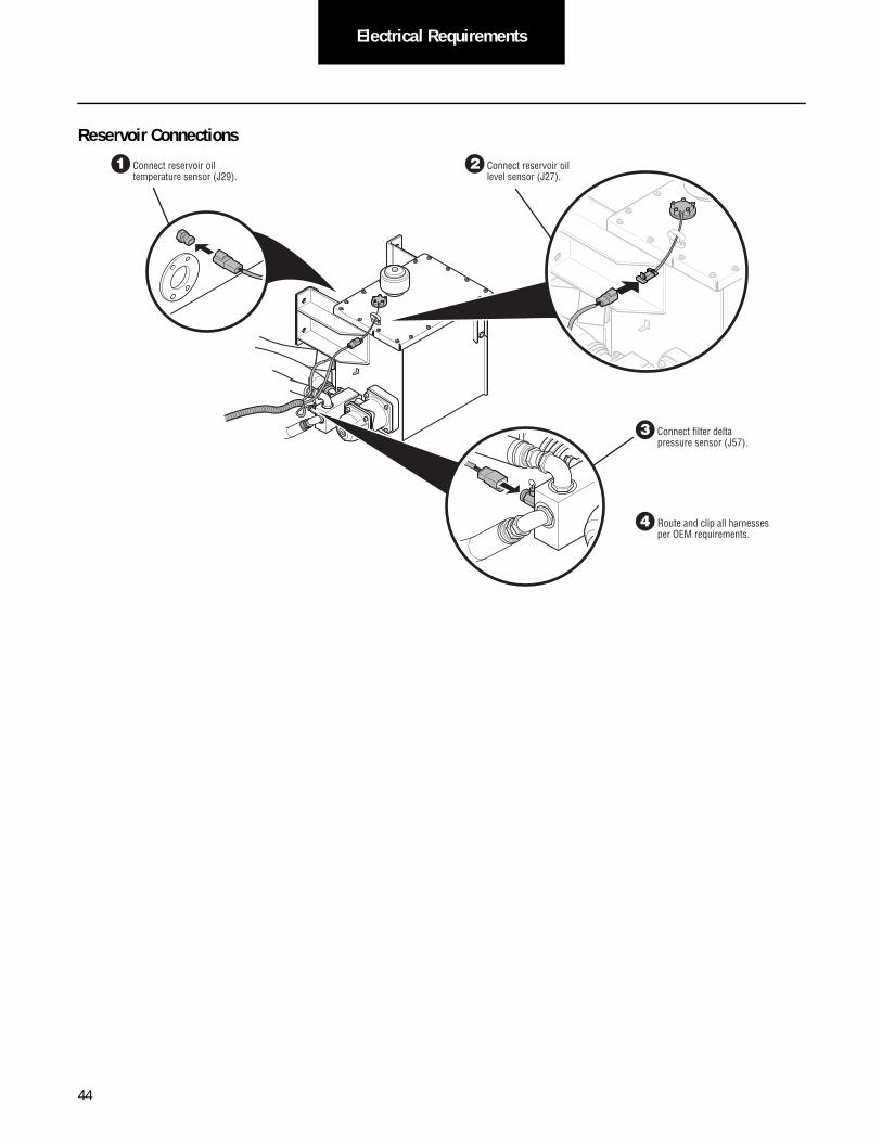
Reservoir Connections
1 Connect reservoir oil temperature sensor (J29).
2 Connect reservoir oil level sensor (J27).
3 Connect fi lter delta pressure sensor (J57).
4 Route and clip all harnesses per OEM requirements.
44

Electrical RequirementsElectrical
Requirements
Accumulator and Cooler Connections
1 Connect high pressure sensor (J31).
2 Connect accumulator proximity sensor (J33).
1 Connect OEM power supply (J74).
2 Connect cooler fan (J69).
45

Electrical Requirements
Chassis Harness Connection to HLA® System
If the installer utilizes an electro-static paint process, the shipping plug must remain connected to the HLA® system during paint.
WARNING
1 Remove shipping plug from ECU and discard.
2 Connect OEM harness and twist to lock in place.
46

Electrical RequirementsElectrical
Requirements
In-Cab Display
The installer is responsible for providing an in-cab display that can communicate system health.
• Displays diagnostic code(s) with a 0-100 numeric display.
• Shows HLA® system state of charge with a horizontal bar graph.
• Indicates system mode state (OFF, ECON, PROD) using a green light.
• A yellow light and the word 'Service' in yellow backlit text to indicate service is needed.
• A red light and the word 'Stop' in red backlit text to indicate an urgent problem.
The in-cab display must be able to receive the in-cab display message as described in the Data Link Requirements section.
47

Electrical Requirements
eVU
Eaton can provide an in-cab display (called the eVU, pronounced “e-view”) that meets all of the necessary requirements. The eVU display can be purchased separately from Eaton's Vehicle Controls and Sensors division. Part ordering information and installa-tion information for the eVU can be found below.
The panel opening for the driver display is defined in the following figure.
The installer shall provide an independent battery connection to provide power to the driver display. Battery voltage shall be within 9 volts to 14 volts. The connection shall be capable of supplying a max current draw of 1 amp. The line shall be fused to 1 amp. The required wiring to support the driver display option can be found in the electrical schematic. It is the installer's respon-sibility to provide the wire harness for the driver display. The pin connection details for the driver display, including connector type and terminals, are defined below.
• NGR Connector: 90-24369
• NGR Terminals: 14-16 AWG: AMP part number 927773 or 927768; 18-20 AWG: AMP part number 927775 or 927771
Part Name Manufacturer Part Number Quantity Required
eVU Driver Display Eaton/Cutler Hammer e00FP0001 1
eVU Driver Display – connector Eaton/Cutler Hammer 25-24787 1
eVU Driver Display – terminal Tyco Electronics/AMP 927771-1 5
HLA System
SERVICE
STOP
OFF ECON PRODE SOC F
1.734 in
[44.04 mm]
0.867 in
[22.02 mm]
Panel Opening
Note:
1. Views are dual dimensioned – in [mm].2. Product is designed to mount in panels between
0.039 in and 0.157 in [1 mm and 4 mm ] thick.
48

Electrical RequirementsElectrical
Requirements
The driver display requires 5 connections:
• Power shall be supplied to the driver display connector pin 5. This power shall be fused to 1 amp, and may switch on and off with vehicle ignition switch.
• Ground shall be supplied to the driver display connector pin 4. This connection shall be continuously connected to a ground connection.
• A connection from the vehicle dimmer switch to the driver display connector pin 2 will allow the display to be dimmed with the vehicle instrument panel.
• A CANbus connection to the HLA® Chassis Harness shall connect from the driver display connector pins 9 and 10 to the HLA® Chassis Harness connector RJ-05 pins A and B for CAN High and CAN Low, respectively.
• Mating connector information for connector RJ-05:
- Supplier: Deutsch or equivalent
- Connector Part Number: DT04-3P-E008 (gray) or DT-3P-EE01 (black)
- Wedge: W3P
- Contacts: 0460-202-16141 or equivalent, nickel plated recommended
Driver Display
Green
5
4
2
3
1
6
9
8
7
10
Yellow
Red
Black
Blue
V(BATT)
COM
To Dimmer
J1939 -
J1939 +
49

Electrical Requirements
50
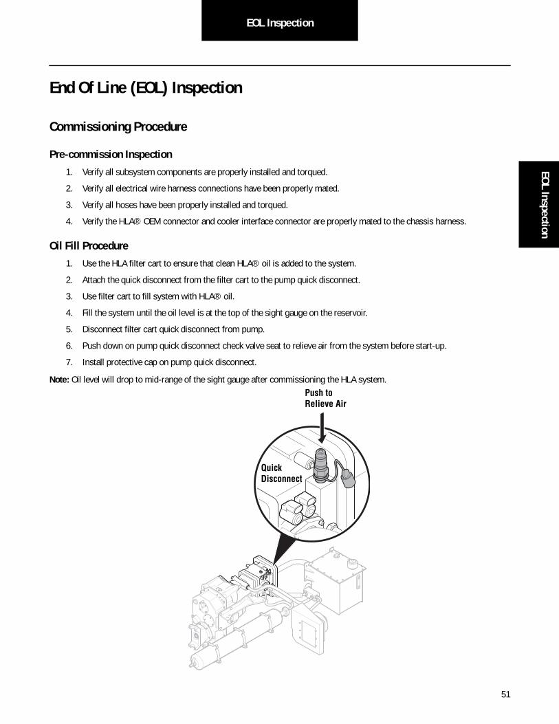
EOL InspectionEOL Inspection
End Of Line (EOL) Inspection
Commissioning Procedure
Pre-commission Inspection
1. Verify all subsystem components are properly installed and torqued.
2. Verify all electrical wire harness connections have been properly mated.
3. Verify all hoses have been properly installed and torqued.
4. Verify the HLA® OEM connector and cooler interface connector are properly mated to the chassis harness.
Oil Fill Procedure
1. Use the HLA filter cart to ensure that clean HLA® oil is added to the system.
2. Attach the quick disconnect from the filter cart to the pump quick disconnect.
3. Use filter cart to fill system with HLA® oil.
4. Fill the system until the oil level is at the top of the sight gauge on the reservoir.
5. Disconnect filter cart quick disconnect from pump.
6. Push down on pump quick disconnect check valve seat to relieve air from the system before start-up.
7. Install protective cap on pump quick disconnect.
Note: Oil level will drop to mid-range of the sight gauge after commissioning the HLA system.
Quick Disconnect
Push to Relieve Air
51

EOL Inspection
System Air Purge
The purging process is an automated sequence preprogrammed into the HLA® that will purge the system of any air within the system. The procedure requires the vehicle and HLA® systems to be operational, and requires sufficient space so the vehicle can be driven between 5-10 mph for approximately one minute. The process can also be run while the vehicle is on a chassis dyna-mometer.
Necessary Hardware
• PC or Laptop
• Nexiq USB-Link
• ServiceRanger version 3.2 or later (Latest version can be downloaded from www.Roadranger.com)
Procedure
1. Start vehicle.
2. Connect PC to vehicle CAN using Nexiq USB-Link.
3. Start ServiceRanger on PC.
4. Launch APF for “Hydraulic Launch Assist.”
5. Select “Purge” from the Operations Menu.
6. Select “Instructions” link for detailed instructions.
Note: If a fault code is present, refer to TRTS1200 Eaton HLA® Troubleshooting Guide and TRSM1200 Eaton HLA® Service Manual. (Latest versions can be downloaded from www.Roadranger.com)
After the purge sequence is completed, the HLA® system is ready for operational use.
52

Pre-Delivery Inspection (PDI)Pre-Delivery
Inspection (PDI)
Pre-Delivery Inspection (PDI) Procedure
The HLA® system requires Pre-Delivery Inspection (PDI) procedures completed before being put into service. The PDI is typi-cally performed at the dealership level for final vehicle verification prior to release to the end user.
The HLA system requires a final verification to ensure the system is ready for end user operation. Warranty registration with Eaton Real Time Warranty (RTW) is recommended as part of this process.
PDI procedure:
1. Record HLA component serial numbers. Use the Pre-Call Checklist on page 54 or on the RTW web site.
2. Submit HLA serial numbers, chassis VIN, mileage, and in service date via e-mail to [email protected] or on the RTW web site.
3. Ensure the Warning and Caution labels are installed and not covered or damaged.
4. Check HLA accumulator nitrogen precharge pressure.
5. Mark accumulator bladder service tag with in service date.
6. Check HLA system, transfer case, and reservoir fluid levels.
7. Check HLA reservoir breather dirt indicator.
8. Connect ServiceRanger to verify software version is up to date.
9. Set HLA mode to on (Econ or Prod).
10. Test Drive to ensure HLA is operating properly.
Note: Make any needed corrections prior to release to end user.
Note: RTW web site: http://www.roadranger.com/rr/CustomerSupport/Warranty/RealTimeWarranty/index.htm.
53

Pre-Delivery Inspection (PDI)
Real Time Warranty Pre-Call Checklist
Customer/ Owner: Date of Incident:Dealer: Operator/ Driver:
Chassis VIN: Truck ID:Mileage: Hours:
So�ware Revision: Cycle Count:System In Service Date: Accumulator S/N:
HLA Pump S/N: Bladder In Service Date:Fault Codes: T-Case S/N:
FMI: Reservoir S/N:Service/ Stop Lamp: Cooler S/N:
InAc�ve Codes: Fault Count:
RO# Service Complete Date:Data files sent: Screen Shot:
Descrip�on of symtom/ work:
Parts Replaced: Parts Received Date:Part # Serial/ID #Descrip�on
54

Installer CapabilitiesInstaller
Capabilities
Installer Capabilities
Installers shall have the following tools or capabilities when installing an HLA® system.
• Tooling Capabilities
- Transmission jack
- PortaMag drill (retrofit)
- Filter cart
- ServiceRanger
- Nitrogen charging gauge assembly
- Bracket fabrication
• Technical Capabilities
- Hydraulics (mobile)
- Electrical / Electronics and CAN
- Mechanical layout (retrofit)
- Bracket design
53

Installer Capabilities
54

57
Material HandlingM
aterial Handling
Material Handling
The HLA® system utilizes steel hydraulic accumulators to store vehicle kinetic energy during operation. Hydraulic accumulators, when pressurized with dry nitrogen gas, are considered to be hazardous material by the U.S. DOT when shipped by a commercial carrier. All dealerships shipping pressurized accumulators must have their employees complete training for hazardous material shipping certification. For complete details refer to Service Bulletin: TAIB-0824.
Hydraulic Launch Assist High Performance Hydraulic Fluid MSDS sheets are available at roadranger.com. Refer to document MSDS Roadranger HLA® Lubricant.


www.eaton.com/greensolutions
Copyright Eaton, 2012.Eaton hereby grant their customers, vendors, or distributors permission to freely copy, reproduce and/or distribute this document in printed format. It may be copied only in its entirety without any changes or modifications. THIS INFORMATION IS NOT INTENDED FOR SALE OR RESALE, AND THIS NOTICE MUST REMAIN ON ALL COPIES.
Note: Features and specifications listed in this document are subject to change without notice and represent the maximum capabilities of the software and products with all options installed. Although every attempt has been made to ensure the accuracy of information contained within, Eaton makes no representation about the completeness, correctness or accuracy and assumes no responsibility for any errors or omissions. Features and functionality may vary depending on selected options.
For spec’ing or service assistance, call 1-800-826-HELP (4357) or visit www.eaton.com/roadranger.In Mexico, call 001-800-826-4357.
Eaton Vehicle GroupP.O. Box 4013Kalamazoo, MI 49003 USA800-826-HELP (4357)www.eaton.com/roadranger
Printed in USA
Roadranger: Eaton and trusted partners providing the best products and services in the industry, ensuring more time on the road.