Embed Size (px)
Citation preview

EASY-ROTOR-CONTROL M Operation-guide
__________________________________________________________________________________________
© Ing.-Büro E. Alba de Schmidt Page 1 web : www.schmidt-alba.de Tannenstr. 16 email : [email protected] 86836 Untermeitingen / Germany This document is for the user only. Any publishing (printed or in electronic form) is not allowed.
INDEX
General information regarding operations: ................................................................................ 2
1. Connectors.............................................................................................................................. 3
1.1 ERC-M USB .................................................................................................................... 3
1.2 ERC-M RS232 ................................................................................................................. 3
1.2 ERC-M LAN-option ........................................................................................................ 3
2. Housings................................................................................................................................. 4
2.1 Slimline-case .................................................................................................................... 4
2.2 Desktop-housing............................................................................................................... 4
3. DC-supply of ERC-M ............................................................................................................ 5
3.1. DC-supply through the DC-connector of ERC-M .......................................................... 5
3.2. DC-supply through USB ................................................................................................. 5
3.3. DC-supply through the rotator-control-box .................................................................... 5
4. Operation-modes of ERC-M .................................................................................................. 6
4.1. ERC-M attached to a PC by RS232 ................................................................................ 6
4.2. ERC-M attached to a PC by USB ................................................................................... 6
4.3. ERC-M attached to a PC by LAN................................................................................... 6
4.4. Single PC controls several ERC-M by RS232 or USB................................................... 7
4.5. Single PC controls several ERC-M by LAN................................................................... 7
4.6. Several PC control 1 ERC-M over LAN......................................................................... 8
4.7. Several PC control several ERC-M over LAN ............................................................... 8
4.8. ERC-M Master-Slave-Mode over RS232 ....................................................................... 9
4.9. ERC-M Master-Slave-mode over LAN .......................................................................... 9
4.10. ERC-M Master-Slave-mode over Internet .................................................................. 10
Appendix 1: Assign a COM-port to ERC-M USB................................................................... 11
Appendix 2: Assign an IP-address to ERC-M LAN-option..................................................... 12
Appendix 3: Assign a COM-port to ERC-M LAN-option....................................................... 13
Appendix 4: Settings of the LAN interface for Slave-mode.................................................... 14
Appendix 4.1: Configuration by the WEB-interface ........................................................... 14
Appendix 4.2: Configuration by a Telnet-session................................................................ 16
Appendix 5: Settings of the LAN interface for Master-mode.................................................. 18
Appendix 5.1: Configuration by the WEB-interface ........................................................... 18
Appendix 5.2: Configuration by a Telnet-session................................................................ 21
Appendix 6: Make the Slave visible on the Internet ................................................................ 23

EASY-ROTOR-CONTROL M Operation-guide
__________________________________________________________________________________________
© Ing.-Büro E. Alba de Schmidt Page 2 web : www.schmidt-alba.de Tannenstr. 16 email : [email protected] 86836 Untermeitingen / Germany This document is for the user only. Any publishing (printed or in electronic form) is not allowed.
General information regarding operations: This document shall help you to set your system up regarding your specific demands. With this document we cover the items: - connectors on the ERC-M - different housings of the ERC-M - DC-supply of the ERC-M - 10 different operation-modes of ERC-M by use of different interfaces showing the possible setups in a home-station, in a contest-station in multiple operator/multiple antenna-setups or remote-stations. We are afraid we cannot handle all possible setups in this document, so if you have any questions just contact us or use the Easy-Rotor-Control Yahoo-Group to connect to other users.
http://groups.yahoo.com/group/Easy_Rotor_Control/

EASY-ROTOR-CONTROL M Operation-guide
__________________________________________________________________________________________
© Ing.-Büro E. Alba de Schmidt Page 3 web : www.schmidt-alba.de Tannenstr. 16 email : [email protected] 86836 Untermeitingen / Germany This document is for the user only. Any publishing (printed or in electronic form) is not allowed.
1. Connectors
1.1 ERC-M USB
DC-supply
USB Rotators
HID
1.2 ERC-M RS232
DC-supply
Rotators
RS232
HID
1.2 ERC-M LAN-option
LAN

EASY-ROTOR-CONTROL M Operation-guide
__________________________________________________________________________________________
© Ing.-Büro E. Alba de Schmidt Page 4 web : www.schmidt-alba.de Tannenstr. 16 email : [email protected] 86836 Untermeitingen / Germany This document is for the user only. Any publishing (printed or in electronic form) is not allowed.
2. Housings ERC-M is available with different housings. A Slimline-case and a Desktop-housing
2.1 Slimline-case
DC-supply USB RS232 LAN Rotators
2.2 Desktop-housing
The Desktop-housing is available with 2 different front-panels: AZ/EL and AZ/AZ.
Electrically they have the same function and they use the same PCB but the pushbuttons and
the LEDs are arranged differently.
Frontpanel AZ/EL Frontpanel AZ/AZ
Display
LEDs for AUX-channels Pushbuttons and LEDs for direction

EASY-ROTOR-CONTROL M Operation-guide
__________________________________________________________________________________________
© Ing.-Büro E. Alba de Schmidt Page 5 web : www.schmidt-alba.de Tannenstr. 16 email : [email protected] 86836 Untermeitingen / Germany This document is for the user only. Any publishing (printed or in electronic form) is not allowed.
Backpanel
Rotators DC-supply USB RS232 LAN
3. DC-supply of ERC-M There are 3 ways to supply the ERC-M.
3.1. DC-supply through the DC-connector of ERC-M
DC is supplied through the DC-connector with is a DC-jack with a 2.1mm pin and 5.5mm
outer diameter. The plus-pole is the centre-pin.
Note: The supply through the DC-connector is always needed if rotor-cards or the
LAN-option is used.
The supply is 10..15VDC with a minimum of 300mA. Be sure the voltage does not drop
below 10V if a rotor-card is used. Otherwise the relays may not engage properly.
The needed connector is supplied with the ERC-M.
3.2. DC-supply through USB
Without rotor-cards or LAN-option the needed current for the ERC-M is less than 100mA and
can be retrieved from USB (USB-powered).
3.3. DC-supply through the rotator-control-box
Some rotators supply DC through the remote-connector of the rotator-control-box. Please
check the ERC-M installation-guide if your rotator supplies a suitable DC.

EASY-ROTOR-CONTROL M Operation-guide
__________________________________________________________________________________________
© Ing.-Büro E. Alba de Schmidt Page 6 web : www.schmidt-alba.de Tannenstr. 16 email : [email protected] 86836 Untermeitingen / Germany This document is for the user only. Any publishing (printed or in electronic form) is not allowed.
4. Operation-modes of ERC-M There are several ways to operate an ERC-M:
4.1. ERC-M attached to a PC by RS232
RS232-cable supplied with ERC-M (3.5mm phone-jack to D-SUB9)
ERC-M RS232
4.2. ERC-M attached to a PC by USB
A COM-port needs to be assigned to the ERC-M USB (see Appendix 1)
USB-cable supplied with ERC-M (USB-A to USB-B)
ERC-M USB
4.3. ERC-M attached to a PC by LAN
An IP-address needs to be assigned to the ERC-M LAN-option (see Appendix 2).
A COM-port needs to be assigned to the ERC-M LAN-option (see Appendix 3).
Patch-cables are not supplied with ERC-M LAN-option
Crossover-cable supplied with ERC-M LAN-option
ERC-M LAN
Patch-cable Patch-cable
ERC-M LAN
EASY-ROTOR-CONTROL M Operation-guide
__________________________________________________________________________________________
© Ing.-Büro E. Alba de Schmidt Page 7 web : www.schmidt-alba.de Tannenstr. 16 email : [email protected] 86836 Untermeitingen / Germany This document is for the user only. Any publishing (printed or in electronic form) is not allowed.
4.4. Single PC controls several ERC-M by RS232 or USB
Every ERC-M uses a specific COM-port. Either a RS232-port or a COM-port assigned by the
USB-to-serial-adapter (FTDI) on the ERC-M USB (see Appendix 1)
ERC-M RS232 or USB
RS232- or USB-cables supplied with kit
4.5. Single PC controls several ERC-M by LAN
Every ERC-M uses a specific COM-port assigned to the ERC-M LAN-option (see Appendix
2 and 3)
ERC-M LAN
Patch-cables
Patch-cable

EASY-ROTOR-CONTROL M Operation-guide
__________________________________________________________________________________________
© Ing.-Büro E. Alba de Schmidt Page 8 web : www.schmidt-alba.de Tannenstr. 16 email : [email protected] 86836 Untermeitingen / Germany This document is for the user only. Any publishing (printed or in electronic form) is not allowed.
4.6. Several PC control 1 ERC-M over LAN
On every PC a COM-port is assigned to the ERC-M LAN-option (see Appendix 2 and 3).
The ERC-M LAN-option can only be connected to one PC at a time.
If one PC opens the COM-port to the ERC-M, the other PCs cannot establish a connection.
In the moment an existing connection is closed, the ERC-M is available again for other
connections.
Patch-cables
ERC-M LAN
Patch-cable
4.7. Several PC control several ERC-M over LAN
On every PC a COM-port is assigned to each ERC-M LAN-option (see Appendix 2 and 3).
As these COM-ports are assigned locally in each PC, the COM-port-number may differ on
different PCs for the same ERC-M LAN-option
An ERC-M LAN-option can only be connected to one PC at a time.
If one PC opens the COM-port to the an ERC-M, the other PCs cannot establish a connection
to the same ERC-M.
In the moment an existing connection is closed, the ERC-M is available again for other
connections.
Patch cables
Patch cables

EASY-ROTOR-CONTROL M Operation-guide
__________________________________________________________________________________________
© Ing.-Büro E. Alba de Schmidt Page 9 web : www.schmidt-alba.de Tannenstr. 16 email : [email protected] 86836 Untermeitingen / Germany This document is for the user only. Any publishing (printed or in electronic form) is not allowed.
4.8. ERC-M Master-Slave-Mode over RS232
This mode was developed to support remote-stations without a PC on the remote- and on the
host-side.
The Master is an ERC-M RS232 with a desktop-housing (LCD, LEDs and pushbuttons).
The Slave is an ERC-M RS232 with or w/o housing.
Master and Slave needs to be configured with Service-Tool V3.0 or higher.
Master and Slave needs a Firmware V3.0 or higher.
The Master must be configured with the Service-Tool to the protocol MASTER.
The Slave must be configured with the Service-Tool to the protocol GS232B.
Master and Slave must be configured with the Service-Tool to the same Baudrate of 9600
Baud.
Master and Slave are connected either by a crossover-RS232-cable (TXD/RXD crossed), a so
called 0- or Nul-modem or by devices that convey the RS232-signals through Ethernet like a
pair of Remoterig®.
If connected to such a RS232-over-Ethernet-device, the connection of TXD and RXD will be
defined by the manufacturer of the device.
MASTER SLAVE
Crossover RS232-cable (phone-jack to phone-jack)
4.9. ERC-M Master-Slave-mode over LAN
This mode was developed to support remote-stations without a PC on the remote- and on the
host-side.
The Master is an ERC-M with LAN-option and a desktop-housing (LCD, LEDs and
pushbuttons).
The Slave is an ERC-M with LAN-option with or w/o housing.
Master and Slave needs to be configured with Service-Tool V3.0 or higher.
Master and Slave needs a Firmware V3.0 or higher.
The Master must be configured with the Service-Tool to the protocol MASTER.
The Slave must be configured with the Service-Tool to the protocol GS232B.
Several settings have to be done to the LAN-devices. Refer to Appendix 4 for the Slave and to
Appendix 5 for the Master.
Master and Slave must be configured with the Service-Tool to the same Baudrate as the
serial-channel of both ERC-M LAN-options.

EASY-ROTOR-CONTROL M Operation-guide
__________________________________________________________________________________________
© Ing.-Büro E. Alba de Schmidt Page 10 web : www.schmidt-alba.de Tannenstr. 16 email : [email protected] 86836 Untermeitingen / Germany This document is for the user only. Any publishing (printed or in electronic form) is not allowed.
Master and Slave are connected either by a crossover-cable or by a hub and patch-cables.
Crossover-cable supplied with ERC-M LAN-option
Patch-cable Patch-cable
4.10. ERC-M Master-Slave-mode over Internet
All configurations for this setup are the same as in 4.9.
In addition the Slave must be made visible to the internet. Refer to Appendix 6.
INTERNET
Patch-cable Patch-cable
Internet

EASY-ROTOR-CONTROL M Operation-guide
__________________________________________________________________________________________
© Ing.-Büro E. Alba de Schmidt Page 11 web : www.schmidt-alba.de Tannenstr. 16 email : [email protected] 86836 Untermeitingen / Germany This document is for the user only. Any publishing (printed or in electronic form) is not allowed.
Appendix 1: Assign a COM-port to ERC-M USB - The ERC-M USB has a build-in USB-to-serial-adapter based on a FTDI-chip.
- In most cases and with most operating-systems you simply need to connect the ERC-
M to the PC with the USB-cable and a COM-port will be assigned to the ERC-M.
- In all other cases you might be asked for a driver. These drivers are available on the
CD in the folder Drivers.
- After a successful installation you will find a new serial-port in the device-manager.
- Open the device-manager in order to know, which COM-port has been assigned to the
ERC-M.

EASY-ROTOR-CONTROL M Operation-guide
__________________________________________________________________________________________
© Ing.-Büro E. Alba de Schmidt Page 12 web : www.schmidt-alba.de Tannenstr. 16 email : [email protected] 86836 Untermeitingen / Germany This document is for the user only. Any publishing (printed or in electronic form) is not allowed.
Appendix 2: Assign an IP-address to ERC-M LAN-option - Install the Lantronix®-Device-Installer on your PC. The setup-file is in the folder
LANTRONIX on the CD delivered with our ERC-M. The name of the setup-file is
setup_di_x86x64cd_n.n.n.n.exe where n.n.n.n is the current version (e.g. 4.3.0.7).
Newer versions might be available on the Lantronix®-homepage at
http://www.lantronix.com/device-networking/utilities-tools/device-installer.html
- Connect your ERC-M with the crossover-LAN-cable to your PC or with a patch-cable
to the hub where your PC is connected to.
- Start the Device-Installer
- After start-up Device-Installer will show you the Lantronix®-devices (XPORT)
connected to your PC or network.
- If the XPORT has not been configured yet, it will have an IP-adress of 0.0.0.0.
- Mark the XPORT in the device-list.
- Press Assign IP from the top-menu to assign an IP-address to your specific XPORT.
- NOTE: The ERC-M LAN-option uses a Lantronix® XPORT. More information on
the usage of the Lantronix®-Device-Installer (DI) and the XPORT is available in the
SUPPORT-section of the www.lantronix.com web-site.
EASY-ROTOR-CONTROL M Operation-guide
__________________________________________________________________________________________
© Ing.-Büro E. Alba de Schmidt Page 13 web : www.schmidt-alba.de Tannenstr. 16 email : [email protected] 86836 Untermeitingen / Germany This document is for the user only. Any publishing (printed or in electronic form) is not allowed.
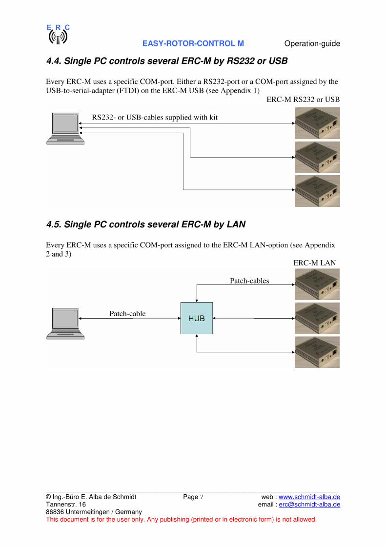
Appendix 3: Assign a COM-port to ERC-M LAN-option - Install the Lantronix®-COM-Port-Redirector on your PC. The setup-file is in the
folder LANTRONIX on the CD delivered with our ERC-M. The name of the setup-
file is setup_cpr_x86x64cd_n.n.n.n.exe where n.n.n.n is the current version (e.g.
4.3.0.1). Later versions might be available on the Lantronix®-homepage at
http://www.lantronix.com/device-networking/utilities-tools/com-port-redirector.html
- Connect your ERC-M with the crossover-LAN-cable to your PC or with a patch-cable
to the hub where your PC is connected to.
- Start the Lantronix®-COM-Port-Redirector (CPR)
- After start-up press Search For Devices on the top-menue and CPR will show you
available devices:
- Press Add/Remove on the top-menu and choose the COM-port-number where you
want to connect your LAN-device
Double-click on the COM-port in the Com Port List and you will get this window:
- Now double-click on the device in the Device-List and the Host-IP and TCP-port will
be populated automatically
- Now press the Save-button on the top-menu and you are done.
- NOTE: The ERC-M LAN-option uses a Lantronix® XPORT. More information on
the usage of the Lantronix®-COM-Port-Redirector (CPR) and the XPORT is available
in the SUPPORT-section of the www.lantronix.com web-site.
- NOTE: When configuring a remote ERC-M LAN-option over the INTERNET you
will have to enter the IP-address manually as the Lantronix®-COM-Port-Redirector
only discovers devices locally attached to your network.

EASY-ROTOR-CONTROL M Operation-guide
__________________________________________________________________________________________
© Ing.-Büro E. Alba de Schmidt Page 14 web : www.schmidt-alba.de Tannenstr. 16 email : [email protected] 86836 Untermeitingen / Germany This document is for the user only. Any publishing (printed or in electronic form) is not allowed.
Appendix 4: Settings of the LAN interface for Slave-mode
There are 2 ways of configuring a ERC-M Xport LAN Interface:
- by use of the WEB-interface programmed inside the XPORT
- by use of a Telnet-session
In appendix 4.1 you will find the configuration by the original XPORT WEB-interface
and in appendix 4.2 the configuration by a Telnet-session
Appendix 4.1: Configuration by the WEB-interface
- Open the WEB-interface of the Lantronix®-Xport by typing the IP-address of the
Slave in the URL-address of your browser. Example for Firefox®:
- A user-name and password is requested. The default value is blank, so if you have not
assigned a password yet, just press OK.
- Select Channel 1 / Serial Settings on the main-menu and make the settings as shown:

EASY-ROTOR-CONTROL M Operation-guide
__________________________________________________________________________________________
© Ing.-Büro E. Alba de Schmidt Page 15 web : www.schmidt-alba.de Tannenstr. 16 email : [email protected] 86836 Untermeitingen / Germany This document is for the user only. Any publishing (printed or in electronic form) is not allowed.
- Click the OK-Button.
- Select Channel 1 / Connection on the main-menu and make the settings as shown:
- Click the OK-Button.
- Now select Apply Settings from the main-menu and wait until the device has
rebooted.
- Close the WEB-interface and you are done.

EASY-ROTOR-CONTROL M Operation-guide
__________________________________________________________________________________________
© Ing.-Büro E. Alba de Schmidt Page 16 web : www.schmidt-alba.de Tannenstr. 16 email : [email protected] 86836 Untermeitingen / Germany This document is for the user only. Any publishing (printed or in electronic form) is not allowed.
Appendix 4.2: Configuration by a Telnet-session
- Open a "DOS Command" Window also know as a "Command Prompt", this can be
done by typing "CMD" and ENTER in the COMMAND window in your start menu
or selecting the "Command Prompt" from the accessory submenu in start menu
- At the command prompt type in "telnet 192.168.178.202 9999" (where the
192.168.178.202 is the IP address of the Slave unit and 9999 is the required port
number to get access) and hit ENTER .
- NOTE: The IP Address used in this example (192.168.178.202) is the one we used in
our lab, your may change according to your settings.
- You will get the following response:
o MAC address 00204A123456
Software version V6.X.X.X (12345) XPTEXE
Press Enter for Setup Mode
- Once you got this press ENTER
- The ERC-M Xport LAN Interface main menu will now come up listing all the
present configuration of your ERC-M Xport LAN Interface:
o Change Setup:
0 Server
1 Channel 1
3 E-mail
5 Expert
6 Security
7 Defaults
8 Exit without save
9 Save and exit Your choice ?
- Next type "0" (note this is a numeric number ZERO and not an uppercase letter O) and
ENTER.
- Fill in the value like this
o IP Address : (192) .(168) .(178) .(202)
Set Gateway IP Address (Y) ?
Gateway IP addr (192) .(168) .(178) .(001)
Netmask: Number of Bits for Host Part (0=default) (8)
Set DNS Server IP addr (N) ?
Change Telnet/Web Manager password (N) ?
- This menu is used to configure the ERC-M Xport LAN Interface, some of these
settings like the Gateway and Netmask must be changed because there default values
may not be set properly for your network. You must validate all these settings
according to the specifics of the local area network where the Slave is connected.
- In this example; The ERC-M Xport LAN Interface Slave IP address was set to
192.168.178.202, with a Gateway of 192.168.178.001 and a netmask of 8 (8 is
255.255.255.000 mask also known as a Class C)
- NOTE: The present settings are not changed if you simply hit ENTER. and the ERC-
M Xport LAN Interface setup menu is listed once you are done.
- for more information on the XPORT configuration please refer to the XPORT user
guide in the support/Documentation section of the WWW.LANTRONIX.COM

EASY-ROTOR-CONTROL M Operation-guide
__________________________________________________________________________________________
© Ing.-Büro E. Alba de Schmidt Page 17 web : www.schmidt-alba.de Tannenstr. 16 email : [email protected] 86836 Untermeitingen / Germany This document is for the user only. Any publishing (printed or in electronic form) is not allowed.
- Now we are ready to configure the serial port communication. In the setup menu select
channel 1 by typing "1" and ENTER;
- Fill in the value like this:
o Baudrate (9600) ?
I/F Mode (4C) ?
Flow (00) ?
Port No (10001) ?
ConnectMode (C0) ?
Send '+++' in Modem Mode (N) ?
Show IP addr after 'RING' (N) ?
Auto increment source port (N) ?
Remote IP Address : (000) .(000) .(000) .(000)
Remote Port (0) ?
DisConnMode (00) ?
FlushMode (77) ?
DisConnTime (00:00) ?:
SendChar 1 (00) ?
SendChar 2 (00) ?
- This (See above) is what the ERC-M Xport LAN Interface Slave configuration
MUST be setup to.
- WARNING: Do not change any of the settings from the recommended configuration
as shown above, changing these values will prevent proper ERC-M Xport LAN
Interface operation.
- Now you are ready to Save your configuration and Exit from the TelNet session by
typing "9" (Save and Exit) and ENTER.
- You are done with your ERC-M Xport LAN Interface Slave configuration

EASY-ROTOR-CONTROL M Operation-guide
__________________________________________________________________________________________
© Ing.-Büro E. Alba de Schmidt Page 18 web : www.schmidt-alba.de Tannenstr. 16 email : [email protected] 86836 Untermeitingen / Germany This document is for the user only. Any publishing (printed or in electronic form) is not allowed.
Appendix 5: Settings of the LAN interface for Master-mode
There are 2 ways of configuring a ERC-M Xport LAN Interface:
- by use of the WEB-interface programmed inside the XPORT
- by use of a Telnet-session
In appendix 5.1 you will find the configuration by the original XPORT WEB-interface
and in appendic 5.2 the configuration by a Telnet-session
Appendix 5.1: Configuration by the WEB-interface
- open the WEB-interface of the Lantronix®-Xport by typing the IP-adress of the
Master in the URL-address of your browser. Example for Firefox®:
- A user-name and password is requested. The default value is blank, so if you have not
assigned a password yet, just press OK.
- Select Channel 1 / Serial Settings on the main-menu and make the settings as shown:

EASY-ROTOR-CONTROL M Operation-guide
__________________________________________________________________________________________
© Ing.-Büro E. Alba de Schmidt Page 19 web : www.schmidt-alba.de Tannenstr. 16 email : [email protected] 86836 Untermeitingen / Germany This document is for the user only. Any publishing (printed or in electronic form) is not allowed.
- Click the OK-Button.
- Select Channel 1 / Connection on the main-menu and make the settings as shown:
- The IP-address at the item Remote Host must be the IP-address of the Slave.
- Click the OK-Button.

EASY-ROTOR-CONTROL M Operation-guide
__________________________________________________________________________________________
© Ing.-Büro E. Alba de Schmidt Page 20 web : www.schmidt-alba.de Tannenstr. 16 email : [email protected] 86836 Untermeitingen / Germany This document is for the user only. Any publishing (printed or in electronic form) is not allowed.
- Select Network on the main-menu and make the settings as shown:
- The IP-address configuration is very important and should always have a proper
MASK and GATEWAY configured.
- Your gateway in most cases should be your main ROUTER device where your
FIREWALL is configured.
- Click the OK-Button.
- Now select Apply Settings from the main-menu and wait until the device has
rebooted.
- Close the WEB-interface and you are done.

EASY-ROTOR-CONTROL M Operation-guide
__________________________________________________________________________________________
© Ing.-Büro E. Alba de Schmidt Page 21 web : www.schmidt-alba.de Tannenstr. 16 email : [email protected] 86836 Untermeitingen / Germany This document is for the user only. Any publishing (printed or in electronic form) is not allowed.
Appendix 5.2: Configuration by a Telnet-session
- Open a "DOS Command" Window also know as a "Command Prompt", this can be
done by typing "CMD" and ENTER in the COMMAND window in your start menu or
selecting the "Command Prompt" from the accessory submenu in start menu.
- At the command prompt type in "telnet 192.168.178.201 9999" (where the
192.168.178.201 is the IP address of the Master unit and 9999 is the required port
number to get access) and hit ENTER .
- NOTE: The IP Address used in this example (192.168.178.201) is the one we used in
our lab, your may change according to your settings.
- You will get the following response:
o MAC address 00204A123456
Software version V6.X.X.X (12345) XPTEXE
Press Enter for Setup Mode
- Once you got this press ENTER
- The ERC-M Xport LAN Interface main menu will know come up listing all the
present configuration of your ERC-M Xport LAN Interface:
o Change Setup:
0 Server
1 Channel 1
3 E-mail
5 Expert
6 Security
7 Defaults
8 Exit without save
9 Save and exit Your choice ?
- Next type "0" (note this is a numeric number ZERO and not an uppercase letter O) and
ENTER.
- Fill in the value like this
o IP Address : (192) .(168) .(178) .(201)
Set Gateway IP Address (Y) ?
Gateway IP addr (192) .(168) .(178) .(001)
Netmask: Number of Bits for Host Part (0=default) (8)
Set DNS Server IP addr (N) ?
Change Telnet/Web Manager password (N) ?
- This menu is used to configure the ERC-M Xport LAN Interface, some of these
settings like the Gateway and Netmask must be changed because there default values
may not be set properly for your network. You must validate all these settings
according to the specifics of the local area network where the Slave is connected.
- In this example; The ERC-M Xport LAN Interface Slave IP address was set to
192.168.178.201, with a Gateway of 192.168.178.001 and a netmask of 8 (8 is
255.255.255.000 mask also known as a Class C)
- NOTE: The present settings are not changed if you simply hit ENTER. and the ERC-
M Xport LAN Interface setup menu is listed once you are done.
- for more information on the XPORT configuration please refer to the XPORT user
guide in the support/Documentation section of the WWW.LANTRONIX.COM

EASY-ROTOR-CONTROL M Operation-guide
__________________________________________________________________________________________
© Ing.-Büro E. Alba de Schmidt Page 22 web : www.schmidt-alba.de Tannenstr. 16 email : [email protected] 86836 Untermeitingen / Germany This document is for the user only. Any publishing (printed or in electronic form) is not allowed.
- Now we are ready to configure the serial port communication. In the setup menu select
channel 1 by typing "1" and ENTER;
- Fill in the value like this:
o Baudrate (9600) ?
I/F Mode (4C) ?
Flow (00) ?
Port No (10001) ?
ConnectMode (C5) ?
Send '+++' in Modem Mode (N) ?
Show IP addr after 'RING' (N) ?
Auto increment source port (N) ?
Remote IP Address : (082) .(143) .(055) .(123)
Remote Port (10001) ?
DisConnMode (00) ?
FlushMode (77) ?
DisConnTime (00:00) ?:
SendChar 1 (00) ?
SendChar 2 (00) ?
- This (See above) is what the ERC-M Xport LAN Interface Master configuration
MUST be setup to to automatically connect to the Slave. - Some of the differences in this configuration between the Slave and Master unit are:
o "ConnecMode" in the Slave is set to C0 and in the Master C5, a C5 is to
generate automaticaly a connection to the Slave address set in the "Remote IP
Address" field in this menu.
o "Remote IP Address" is used to set the IP address of the Slave so that the
Master will know how to reach the Slave. In this example 082.143.055.123 is
the IP address of the remote site where my Slave is installed (See note for more
information)
o "Remote Port" is very important parameter and MUST beset the same as the
"Port No" on the Slave, if not the connection will never be established.
- NOTE: In the example used in this manual the "IP address" that was set in the ERC-
M Xport LAN Interface Slave (192.168.178.202) was different from the "Remote IP
Address" that was set in the Master (082.143.055.123).
The reason why in some situation like this one these are different is that our remote
device is in a different physical site away from our labs local LAN Network and
connected via the INTERNET.
Because of this our Internet service provider on the Slave site will supply us a IP
address for our INTERNET connection (082.143.055.123) that is then used by our
ROUTER and converted to the local IP address used by the Slave (192.168.178.202)
in the Firewall settings of our ROUTER.
Please refer to your ROUTER documentation and INTERNET provider for more
information on this subject.
- Now you are ready to Save your configuration and Exit from the TelNet session by
selecting typing "9" (Save and Exit) and ENTER.
- You are done with your ERC-M Xport LAN Interface Master configuration

EASY-ROTOR-CONTROL M Operation-guide
__________________________________________________________________________________________
© Ing.-Büro E. Alba de Schmidt Page 23 web : www.schmidt-alba.de Tannenstr. 16 email : [email protected] 86836 Untermeitingen / Germany This document is for the user only. Any publishing (printed or in electronic form) is not allowed.
Appendix 6: Make the Slave visible on the Internet To configure you ERC-M Xport LAN Interface Master and Slave properly to communicate
over an INTERNET link you must configure your networks properly. Some of the important
point to always be very carefull of are:
- The ERC-M Xport LAN Interface Local IP-address configuration is very important
and should always have a proper MASK and GATEWAY configured. These are
specific to your network and a basic knowledge of your network configuration is
required.
- Your gateway in most cases should be your ROUTER device where your FIREWALL
is configured.
- Now you need to make the IP-address available to the outside-world this process will
be different on most router units. This would normally be done in your Router
Firewall section where you would configure your firewall to point any outside request
from the INTERNET to a specific IP Address or a group of IP address inside your
local area network (LAN).
- On the REMOTE site, you must configure your Router so that the IP address of your
ERC-M Xport LAN Interface Slave is listed on the Firewall and made available to
the INTERNET.
- The following ports should also be opened in your REMOTE firewall for that IP
address; 23, 80, 9999 and 10001. You may also need to make these same ports
available on the ROUTER of the site where your ERC-M Xport LAN Interface
Master is installed
- This section of the firewall router configuration is often known as a DMZ
(demilitarized Zone) please refer to your ROUTER documentation or manufacturer
support web site for more information on your ROUTER Firewall or DMZ settings.
- Most typical internet-user don’t have a fixed-IP, this may cause you some problems
since INTERNET service providers will change your INTERNET IP address on
regular basis, anywhere from a few weeks, days or even hours and for the ERC-M
Xport LAN Interface Master to connect to the ERC-M Xport LAN Interface Slave
you MUST know the IP Address for the ERC-M Xport LAN Interface Slave.
- INTERNET Service Providers will NOT give you STATIC INTERNET IP Address
unless you pay extra for this service.

EASY-ROTOR-CONTROL M Operation-guide
__________________________________________________________________________________________
© Ing.-Büro E. Alba de Schmidt Page 24 web : www.schmidt-alba.de Tannenstr. 16 email : [email protected] 86836 Untermeitingen / Germany This document is for the user only. Any publishing (printed or in electronic form) is not allowed.
- This means your remote IP Address may change on a regular basis, tools like
http://whatismyipaddress.com/ if you run them on the remote site will help you
figure out what is your IP address has changed to, problem here is that you most likely
won't be on the remote site.
- other services like DYNDNS or http://www.no-ip.com/ will offer you a fix DNS that
will adapt itself to your changing INTERNET Service provider IP address, their web
site will offer you support in setting this up.