Embed Size (px)
Citation preview
EASTERN MICHIGAN UNIVERSITY
PAVEMENT RECOMMENDATIONS GEOTECHNICAL GUIDELINES
CONSULTANT SITE DESIGN GUIDELINES CONSTRUCTION SPECIFICATIONS
PREPARED FOR: EASTERN MICHIGAN UNIVERSITY
YPSILANTI, MICHIGAN
APRIL 22, 2013 PROJECT NO. G130086
TABLE OF CONTENTS
Z:\2013\130086\WORK\REPT\EMU_REPORT.DOCX i
PAVEMENT RECOMMENDATIONS ............................................................................................................ 1 Background Information ........................................................................................................................ 1 Campus Soils from USDA Soil Conservation Survey ........................................................................... 1 Glossary of Terms used in Soil Survey of Washtenaw County............................................................. 2 Engineering Implications of Campus Soil Mapping ............................................................................... 2 Recommended Design Strategies ........................................................................................................ 3 Recommended Construction Strategies ............................................................................................... 3 Implementation of Design and Construction Strategies ........................................................................ 4
GEOTECHNICAL GUIDELINES ................................................................................................................... 5 Scope of Work ....................................................................................................................................... 5 Investigation Report .............................................................................................................................. 5 Soil Borings ........................................................................................................................................... 8 Laboratory Testing ................................................................................................................................ 9
CONSULTANT SITE DESIGN GUIDELINES ............................................................................................. 10 General Background Information ........................................................................................................ 10 Reference Guidelines .......................................................................................................................... 11 Design Elements ................................................................................................................................. 12
LIST OF TABLES Table 1 Flexible and Rigid Pavement ............................................................................................ 8/14 LIST OF APPENDICES Appendix 1 Engineering Properties of Campus Soils Appendix 2 Standard Cross-Sections LIST OF ABBREVIATIONS/ACRONYMS AASHTO American Association of State Highway and Transportation Officials ACI American Concrete Institute ADAAG Americans with Disabilities Act Accessibility Guidelines ANSI American National Standards Institute ASTM American Society for Testing and Materials CBR California Bearing Ratio EMU Eastern Michigan University FHWA Federal Highway Administration FTC&H Fishbeck, Thompson, Carr & Huber, Inc. HMA Hot Mix Asphalt LID Low Impact Development MDOT Michigan Department of Transportation MMUTCD Michigan Manual on Uniform Traffic Control Devices QA/QC Quality Assurance/Quality Control SCS USDA Soil Conservation Service SPT Standard Penetration Test USDA U.S. Department of Agriculture
4/22/2013 1 Z:\2013\130086\WORK\REPT\EMU_REPORT.DOCX
PAVEMENT RECOMMENDATIONS
BACKGROUND INFORMATION
Fishbeck, Thompson, Carr & Huber, Inc. (FTC&H) reviewed existing available data and completed an
onsite inspection of existing on-campus roads and parking lots in December 2012. Readily available data
reviewed included the following:
● USDA Soil Conservation Service Soil Survey of Washtenaw County June 1977
● Washtenaw County Road Commission minimum pavement requirements from their website
● Wayne County Road Commission minimum pavement requirements from their website
● Washtenaw County Water Resource Commission website
● Eastern Michigan University Physical Plant website
● Federal Highway Administration Publication No. NHI-05-037 Geotechnical Aspect of Pavements
● City of Ypsilanti construction standards
● Michigan Department of Transportation (MDOT) Standard Plans
● FTC&H reference specifications
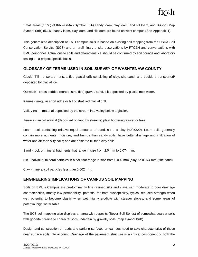
CAMPUS SOILS FROM USDA SOIL CONSERVATION SURVEY
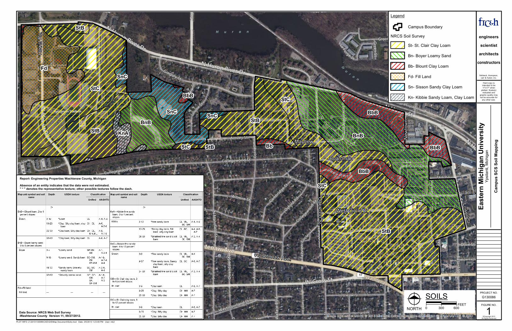
According to the Washtenaw County Soil Survey, the predominant soil series (58.2%) on the Eastern
Michigan University (EMU) Campus is St. Clair clay loam (Map Symbol StB, StC). The permeability of this
soil is very slow. As slopes increase, stormwater runoff is rapid, and the erosion potential is severe.
Unified soil classification for this soil series is CL and CH; AASHTO Classification A-6 and A-7 (See
Appendix 1).
Included in the St. Clair soil mapping are small areas (approximately 7.1%) of Blount loam (Map Symbol
BbB). This poorly drained soil of 2 to 6 percent slopes is typically found on foot slopes and along
drainageways (Huron River). It consists of clay loam to heavy clay loam with slow permeability and
seasonally high water table. Unified classification ML, CL, CH; AASHTO Classification A-4, A-6, and A-7
(See Appendix 1).
Soil mapping on campus also displays an area (20.5%) of Boyer loamy sand (Map Symbol BnB)
extending from east to northwest across campus toward the Huron River (see map). The soil series is
typified by loamy and sandy deposits underlain by coarse gravel. These soils are found on outwash
plains, kames, valley trains, terraces, and moraines. Permeability of this soil is moderately rapid. Unified
classification is SM, SC, SP, SP-SM; American Association of State Highway and Transportation Officials
(AASHTO) Classification is A-2, A-4, and A-6 (See Appendix 1).
4/22/2013 2 Z:\2013\130086\WORK\REPT\EMU_REPORT.DOCX
Small areas (1.3%) of Kibbie (Map Symbol KnA) sandy loam, clay loam, and silt loam, and Sisson (Map
Symbol SnB) (5.1%) sandy loam, clay loam, and silt loam are found on west campus (See Appendix 1).
This generalized description of EMU campus soils is based on existing soil mapping from the USDA Soil
Conservation Service (SCS) and on preliminary onsite observations by FTC&H and conversations with
EMU personnel. Actual onsite soils and characteristics should be confirmed by soil borings and laboratory
testing on a project specific basis.
GLOSSARY OF TERMS USED IN SOIL SURVEY OF WASHTENAW COUNTY
Glacial Till - unsorted nonstratified glacial drift consisting of clay, silt, sand, and boulders transported/
deposited by glacial ice.
Outwash - cross bedded (sorted, stratified) gravel, sand, silt deposited by glacial melt water.
Kames - irregular short ridge or hill of stratified glacial drift.
Valley train - material deposited by the stream in a valley below a glacier.
Terrace - an old alluvial (deposited on land by streams) plain bordering a river or lake.
Loam - soil containing relative equal amounts of sand, silt and clay (40/40/20). Loam soils generally
contain more nutrients, moisture, and humus than sandy soils; have better drainage and infiltration of
water and air than silty soils; and are easier to till than clay soils.
Sand - rock or mineral fragments that range in size from 2.0 mm to 0.074 mm.
Silt - individual mineral particles in a soil that range in size from 0.002 mm (clay) to 0.074 mm (fine sand).
Clay - mineral soil particles less than 0.002 mm.
ENGINEERING IMPLICATIONS OF CAMPUS SOIL MAPPING
Soils on EMU’s Campus are predominantly fine grained silts and clays with moderate to poor drainage
characteristics, mostly low permeability, potential for frost susceptibility, typical reduced strength when
wet, potential to become plastic when wet, highly erodible with steeper slopes, and some areas of
potential high water table.
The SCS soil mapping also displays an area with deposits (Boyer Soil Series) of somewhat coarser soils
with good/fair drainage characteristics underlain by gravelly soils (map symbol BnB).
Design and construction of roads and parking surfaces on campus need to take characteristics of these
near surface soils into account. Drainage of the pavement structure is a critical component of both the
4/22/2013 3 Z:\2013\130086\WORK\REPT\EMU_REPORT.DOCX
design and construction of roads and parking lots. By providing positive drainage requirements in the
design and during construction, infiltrating surface water can be removed from the pavement structure
and not allowed to pond and adversely affect the properties of the subgrade fine grained soils.
The areas of coarser soils may potentially be used for Low Impact Development (LID) design strategies
such as bioswales, bioretention basins, and infiltration trenches. Additional subsurface investigation is
required to evaluate if these areas are suitable for use in LID design strategies.
RECOMMENDED DESIGN STRATEGIES
1. Use well-drained base aggregates and well drained subbase, if required; connect to underdrains;
include good drainage as design criteria (80% of infiltrating water to be removed from pavement
structure within 24 hours of cessation of rainfall) and require a design drainage coefficient of 1.0.
2. Shape and slope clay subgrades to promote lateral movement of infiltrating water within base and
subbase, if applicable, and along subgrade to underdrains for timely removal of subsurface water
from the pavement structure.
3. Use geosynthetics for reinforcement of soft soils particularly along truck or bus routes, if
recommended by geotechnical evaluation.
4. Stabilize heavy clay subgrades, if recommended by geotechnical evaluation.
5. Investigate subsurface soil properties in areas of well drained soils for use as potential bioswales,
bioretention basins, and infiltration trenching (LID design strategies).
6. Include both flexible and rigid pavement options in the design recommendations requested from
geotechnical consultants.
7. Require pavement design be based on AASHTO methodology.
8. Require a detailed geotechnical investigation prior to design to evaluate existing subgrade soils and
recommend pavement cross-section.
RECOMMENDED CONSTRUCTION STRATEGIES
1. Require inspection/testing services during construction activities.
2. Incorporate detailed Quality Assurance/Quality Control (QA/QC) requirements into the contract
specifications.
3. Specify and enforce proof rolling to identify and correct soft, unstable subgrade soils prior to
placement of the subbase and/or base course.
4. Require pavement contractor to be present during proof rolling process.
5. Implement use of penalties for nonconformance of road and parking lot construction contracts.
6. Implement use of warranties of up to 3 years and methodology for enforcement.
4/22/2013 4 Z:\2013\130086\WORK\REPT\EMU_REPORT.DOCX
IMPLEMENTATION OF DESIGN AND CONSTRUCTION STRATEGIES
1. Prepare geotechnical guidelines and requirements for soil borings and geotechnical evaluation prior
to design and construction of roads and parking lots on EMU’s campus.
2. Prepare consultant design guidelines displaying minimum design requirements for all campus roads
and parking lots.
3. Prepare detailed construction specifications for both bituminous and concrete paving.
4. Require pre-pave meetings prior to construction.
5. Incorporate QA/QC specifications into standard contract documents.
6. Incorporate warranties and penalties specifications to be incorporated into standard
contract documents.
4/22/2013 5 Z:\2013\130086\WORK\REPT\EMU_REPORT.DOCX
GEOTECHNICAL GUIDELINES
NOTE: These guidelines are intended as suggested minimum standards. The geotechnical engineer shall
exercise prudent engineering judgment and shall be responsible for selecting testing methods and
frequencies that are appropriate to the scope of the project description. Any suggested deviations from
these proposed minimum standards shall be indicated clearly in the proposal for services to be rendered.
If, during the process of the investigation, the geotechnical engineer discovers that it is necessary to
expand or change the scope of the investigation to accomplish the result described below, he or she shall
notify EMU in writing.
It is EMU’s desire that the pavement system for light duty, standard duty, and heavy duty pavements be
designed and constructed to last a minimum of 15 years without major rehabilitation or replacement.
A. The soils engineer should take this into account in their recommendations for site preparation and
recommendations for design pavement cross-sections.
B. Soil subgrade treatment, full depth reclamation, geotextile reinforcement, permeable aggregate
bases, granular sub bases, underdrains should be recommended if the soils engineer believes they
are necessary for long-term pavement performance for the specific site and subsurface conditions.
SCOPE OF WORK
The purpose of the investigation is to provide a detailed soil evaluation report consisting of borings, soil
sampling, and laboratory testing. The report should also include the geological profile, subsurface
analysis, soil characteristics, and recommendations for pavement types, pavement cross-sections, related
earthwork, and recommendation for onsite construction. The report will provide the basic engineering
data necessary to define and develop the design and construction documents for the project.
INVESTIGATION REPORT
The geotechnical engineer may use an existing topographical map or aerial map for boring locations with
any field adjustments shown. Two benchmarks shall be located at the site and shall be referenced to
U.S. Geological Survey or official EMU datum. If a benchmark has been established by a topographic
survey for the project or previous survey, the report shall use or reference those benchmarks.
A. The investigation report shall be signed by a registered professional engineer, licensed, and
practicing geotechnical engineering in the State of Michigan and shall bear his or her seal. Three (3)
bound copies and one (1) electronic (read-only) version of the report are to be submitted to EMU and
one (1) hard copy and electronic version to the civil engineering consultant.
4/22/2013 6 Z:\2013\130086\WORK\REPT\EMU_REPORT.DOCX
B. The report submitted by the geotechnical engineer describing the results of the investigation should
include at a minimum the following information:
1. Executive summary at the beginning of the report.
2. A map depicting the location of each boring and indicating the general limits of intersections,
entrance drives, parking lots, and reference benchmarks location, if applicable.
3. A log of each boring providing:
a. Date of boring.
b. Boring number.
c. Project name and location.
d. Client: Eastern Michigan University.
e. Ground surface elevation at each hole related to the benchmarks or topographical map.
f. Method used for drilling and sampling.
g. Existing pavement structure; asphalt or concrete, aggregate base, subbase, if applicable.
h. Soil strata with description and classification made from the Unified Soil Classification System
(ASTM D2488) or AASHTO Classification System.
i. Sample depths and types.
j. Penetration resistance (Standard Penetration Test (SPT) and N value) (ASTM D1586).
k. Groundwater and soil moisture observations with depth.
l. Rock coring with Rock Quality Designation values, if authorized.
m. Soil physical and vegetation observations.
n. Summaries of all field and laboratory tests (pocket penetrometer, etc.).
4. The text of the report shall describe:
a. Project location.
b. Topography.
c. Description of subsurface materials including debris, groundwater, or any unusual conditions
that would affect the pavement cross-section design and/or construction.
d. Important vegetation, including location map.
e. Field methodology.
f. Laboratory methods.
5. The report shall discuss pertinent engineering properties of the materials encountered such as:
a. Laboratory index test results.
b. In situ soil moisture with depth.
c. Depth to bedrock.
d. Frost susceptibility.
e. Infiltration values.
f. Perimeter drains and/or underdrain requirements.
4/22/2013 7 Z:\2013\130086\WORK\REPT\EMU_REPORT.DOCX
6. California Bearing Ratio (CBR) or other suitable subgrade modulus used for pavement design.
7. Lateral earth pressure on retaining walls (at-rest, active, and passive) and the corresponding soil
density, angle of internal friction, and estimated coefficient of friction, if required.
8. Dewatering requirements for the proposed construction.
9. Modification or Stabilization of site subgrade soils, if required:
a. For improving the workability of soils having excessive moisture content.
b. Suitability of site soils for stabilization or modification with lime, fly ash, or Portland cement.
c. Recommended concentrations, mixing procedures, depth of treatment, and construction
requirements.
d. Utilize MDOT standard specifications for methods and materials, where applicable.
e. Recommend areas for modification or stabilization.
f. Provide at least two options for owner consideration.
g. Anticipated soil improvements, volume changes, and benefits.
h. Incorporation into pavement cross-section recommendations, if applicable.
i. Required undercuts, if applicable.
10. Site grading and compaction of fill recommendations, including whether existing soils are suitable
for utility trench and pavement structure backfill.
C. Pavement recommendations to include pavement cross-sections for both concrete and hot mix
asphalt (HMA) pavements, for light duty, standard duty, and heavy duty sections.
1. HMA - AASHTO Design Guidelines Flexible Pavement Structures 1993 or the
Mechanistic-Empirical design approach developed under NCHRP 1-37A.
2. Concrete - American Concrete Institute (ACI) 330R - current edition; and/or applicable
ACI standards.
3. Recommendation must also include minimum and maximum lay down thicknesses for
HMA pavement based on MDOT guidelines for the specified pavement materials.
4. Surface course asphalt pavement to be a minimum of 1 1/2″ thick. Surface course asphalt to be
the same thickness for adjacent areas or on the same project.
5. Minimum aggregate drainage coefficient of 1.0 for aggregate base or aggregate
base/subbase combination.
6. Basis of Pavement Design.
4/22/2013 8 Z:\2013\130086\WORK\REPT\EMU_REPORT.DOCX
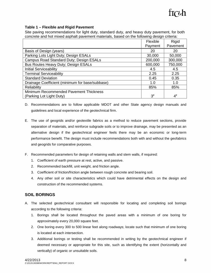
Table 1 – Flexible and Rigid Pavement Site paving recommendations for light duty, standard duty, and heavy duty pavement, for both concrete and hot mixed asphalt pavement materials, based on the following design criteria:
Flexible Payment
Rigid Pavement
Basis of Design (years) 20 20 Parking Lots Light Duty; Design ESALs 30,000 50,000 Campus Road Standard Duty; Design ESALs 200,000 300,000 Bus Routes Heavy Duty; Design ESALs 600,000 750,000 Initial Serviceability 4.5 4.5 Terminal Serviceability 2.25 2.25 Standard Deviation 0.45 0.35 Drainage Coefficient (minimum for base/subbase) 1.0 1.0 Reliability 85% 85% Minimum Recommended Pavement Thickness (Parking Lot Light Duty) 3″ 4″
D. Recommendations are to follow applicable MDOT and other State agency design manuals and
guidelines and local experience of the geotechnical firm.
E. The use of geogrids and/or geotextile fabrics as a method to reduce pavement sections, provide
separation of materials, and reinforce subgrade soils or to improve drainage, may be presented as an
alternative design if the geotechnical engineer feels there may be an economic or long-term
performance benefit. The design must include recommendations both with and without the geofabrics
and geogrids for comparative purposes.
F. Recommended parameters for design of retaining walls and stem walls, if required:
1. Coefficient of earth pressure at rest, active, and passive.
2. Recommended backfill, unit weight, and friction angle.
3. Coefficient of friction/friction angle between rough concrete and bearing soil.
4. Any other soil or site characteristics which could have detrimental effects on the design and
construction of the recommended systems.
SOIL BORINGS
A. The selected geotechnical consultant will responsible for locating and completing soil borings
according to the following criteria:
1. Borings shall be located throughout the paved areas with a minimum of one boring for
approximately every 20,000 square feet.
2. One boring every 300 to 500 linear feet along roadways; locate such that minimum of one boring
is located at each intersection.
3. Additional borings or testing shall be recommended in writing by the geotechnical engineer if
deemed necessary or appropriate for this site, such as identifying the extent (horizontally and
vertically) of organic or unsuitable soils.
4/22/2013 9 Z:\2013\130086\WORK\REPT\EMU_REPORT.DOCX
4. One additional boring at every major drive entrance, every 300 linear feet along service drives,
entrance roads, or as dictated by the size of the project and any special conditions at the site.
5. Borings shall extend to a minimum depth of 5.0 feet below proposed grade (unless fill situation
dictates otherwise) or auger refusal, or deeper if unsuitable soils are found.
6. In addition, one boring every 400 linear feet shall be located along a pipeline route 15 feet deep
(minimum), or 5 feet below the invert of the pipe (if known).
B. The geotechnical consultant must note in the report the new locations of any borings that were
relocated in the field due to access difficulty or utility conflicts.
C. Unless otherwise stipulated, drilling and testing shall be performed in accordance with the latest
editions of applicable ASTM Standards, including, but not limited to ASTM Standards D1586, D1587,
and D2113. Soil samples shall be taken at the ground surface, at 2.5-foot intervals below existing
grade, up to 15 feet deep, then 5-foot intervals to 50 feet deep, then 10-foot intervals beyond 50 feet,
and at each identified change in conditions.
LABORATORY TESTING
A. Laboratory testing shall comply with the latest edition of current applicable ASTM standards
1. Atterberg limits for subgrade soils including in situ moisture contents.
2. Grain size analysis for any onsite soils used in pavement structure.
3. Measured or estimated infiltration rates for moderate to well drained soils that may be used for
LID design strategies.
4. Estimated or calculated CBRs (soaked) or resilient modulus used as the basis of pavement
design for subgrade soils.
4/22/2013 10 Z:\2013\130086\WORK\REPT\EMU_REPORT.DOCX
CONSULTANT SITE DESIGN GUIDELINES These guidelines are intended as suggested minimum standards. The consulting engineer shall exercise
prudent engineering judgment and be responsible for their project drawings and specifications. Any
suggested deviations from these proposed minimum standards shall be indicated clearly in the proposal
for services to be rendered. If during the project, the consulting engineer discovers it is necessary to
expand or change these requirements, he or she shall notify EMU in writing.
The EMU Site Design Guidelines and Construction Standards have been compiled for Engineers and
others retained to provide professional consulting or design services for EMU.
Adherence to the Design Guidelines and Construction Standards is mandatory unless a deviation has
been approved in writing by the EMU Design Representative. Any equal or improved concept method or
product will be given full consideration.
The Design Guidelines and Construction Standards are not intended to be used as specification items.
The architects and engineers are expected to incorporate the items using their own wording and format
unless otherwise directed.
The Design Guidelines and Construction Standards are prepared and published by: Physical Plant
Division, Eastern Michigan University.
Sections of the Design Guidelines and Construction Standards will be revised and updated as experience
or construction developments warrant. Each revised section supersedes all previous editions and
directives concerning construction practices for EMU. The EMU website will always contain the most
current version with the latest revision date indicated.
GENERAL BACKGROUND INFORMATION
1. The EMU campus is primarily pedestrian and bicycle-oriented:
a. Clear physical and visual connections are necessary to facilitate safe and convenient pedestrian
and bicycle movement across the campus.
b. Where practicable, vehicular and pedestrian circulation should be separated.
2. When vehicular, pedestrian, and bicycle circulation is shared or crossed, traffic calming devices such
as tree-lined streets, changes in paving materials, signage, pavement markings, etc., should be
used to ensure pedestrian safety.
3. A physical network of interconnected paths and walkways intermingled with open spaces is essential
to linking buildings for pedestrians and bicycles throughout the campus.
4/22/2013 11 Z:\2013\130086\WORK\REPT\EMU_REPORT.DOCX
4. Visual connectivity also helps pedestrians establish a line of sight and orientation through landmarks.
5. EMU is located adjacent to the Huron River in an area of glacial deposits of moderately well drained
to very poorly drained soils.
a. Subsurface soils range from smaller areas of loamy sand to larger areas of clay loams to heavy
clay loams.
b. To provide long-term performance of paved surfaces, the designer may be required to provide
for collection and transmission of both surface and subsurface stormwater runoffs.
REFERENCE GUIDELINES
1. Eastern Michigan University Construction Standards and Guidelines
2. A Policy on Geometric design of Highways and Streets (2011) as published by AASHTO, Latest
Edition
3. Guidelines for Residential Subdivision Street Design: A Recommended Practice as published by the
Institute of Transportation Engineers (ITE) for local and collector streets
4. Guidelines for Geometric Design of Very Low-Volume Local Roads as published by AASHTO, Latest
Edition
5. Michigan Roundabout Guidelines as published by MDOT, Latest Edition, and current Federal
Highway Administration (FHWA) roundabout guidelines and standards
6. Americans with Disabilities Act Accessibility Guidelines (ADAAG), Latest Edition, and the American
National Standards Institute (ICC/ANSI), and local Building Code
7. Any publications or advisories produced by MDOT’s Complete Streets Advisory Council
8. Applicable Local Building Codes
9. Guide for the Development of Bicycle Facilities, AASHTO, P.O. Box 96716, Washington, DC,
20090-6716, Phone: (888) 227-4860, Latest Edition
10. Improving Conditions for Bicyclists and Pedestrians, A Best Practices Report, FHWA, HEP 10,
400 Seventh Street SW, Washington, DC 20590, Latest Edition
11. ITE Recommended Practice Design and Safety of Pedestrian Facilities, Latest Edition
4/22/2013 12 Z:\2013\130086\WORK\REPT\EMU_REPORT.DOCX
12. Michigan Manual on Uniform Traffic Control Devices (MMUTCD), Latest Edition
13. Hot Mix Asphalt - AASHTO Design Guidelines Flexible Pavement Structures 1993 or the
Mechanistic-Empirical design approach developed under NCHRP 1-37A
14. Concrete - ACI Publication 330R Guide for the Design and Construction of Concrete Parking Lots.
Latest Edition
15. Guidebook of Best Management Practices for Michigan Watersheds, MDEQ Water Quality Division
16. Washtenaw County Water Resource Commissioner: Design Standards, where applicable
17. Low Impact Development Manual for Michigan: A Design Guide for Implementers and Reviewers,
Southeast Michigan Council of Government, September 2008
DESIGN ELEMENTS
1. Design Vehicle:
a. Maximum - AASHTO Bus and WB-40/emergency vehicle.
b. Minimum passenger car.
2. Design Speed:
a. Bus Route and Perimeter Roads - 30 mph.
b. Interior Campus Roads - 30 mph.
c. Others - in accordance with jurisdictional agency requirements.
3. Lane Width:
a. Desirable - 12 feet; 14 feet turning lane.
b. Bike Lanes - 5.0 foot desirable, where applicable.
4. Curb and Gutter:
a. Use 24-inch standard curbs or reverse curbs as required for surface drainage.
b. In areas where snow removal operations are expected:
1) Use 24-inch mountable or rolled curbs.
2) Check with EMU Physical Plant division for locations where snow removal operations are
required on your project
c. Removal and replacement sections - match existing curb section unless otherwise directed.
d. Standard curb height is 6.0 inches, can be increased to 8.0 inches to prevent
vehicular mountings.
4/22/2013 13 Z:\2013\130086\WORK\REPT\EMU_REPORT.DOCX
5. Drainage:
a. The use of underdrains is encouraged in order to extend the life expectancy of
campus pavements.
b. A perforated HDPE (high-density polyethylene) underdrain trench with clean porous stone
wrapped in filter fabric is preferred over sock drains. c. Conveyance systems – 10-year
design storm.
d. Spacing of drainage structures - 350 feet maximum or more frequent as determined
by engineer.
e. Comply with requirements of Washtenaw County Water Resource Commissioner,
where applicable.
f. Design and size to interface with existing storm system and available capacity.
g. Properly locate inlets to ensure proper surface drainage and prevent ponding along campus
roads, at pedestrian crosswalks, or within parking areas.
h. Place drainage structure grates not to interfere with pedestrian movement.
i. Grates along roads - bicycle safe.
j. Use double or multiple grates at low points where required.
k. Consider LID and/or Best Management Practices (BMPs) where practical and cost-effective for
stormwater management
6. Ramps and Driveways:
a. Ramps - MDOT R-28H series.
b. Driveways - MDOT R-29H series.
7. Parking Spaces:
a. 9 feet wide by 18 feet long.
b. Minimum aisle width - 24 feet unless otherwise directed.
c. All parking 90 degrees unless otherwise directed.
d. Angle parking requires written permission from EMU.
e. Comply with current Americans with Disabilities Act of 1990 (ADA) and campus guidelines for
handicap parking requirements.
8. Miscellaneous:
a. Design all concrete structures (precast or cast-in-place) and castings for H-20 vehicle loading.
b. Sidewalks that are vehicle snow-plowed - minimum 6.0 inches concrete over minimum
6.0 inches free draining aggregate.
c. Minimum 4.0-inch sidewalks over minimum 6.0-inch free draining aggregate may be used in
pedestrian only areas with approval of EMU.
4/22/2013 14 Z:\2013\130086\WORK\REPT\EMU_REPORT.DOCX
9. Plans:
a. Plan sheets - 24 inch x 36 inch or 30 inch x 42 inch with north arrow shown.
b. Scale maximum of 1 inch = 50 feet unless otherwise directed.
c. Intersections, cul-de-sacs, sidewalks, and driveways - use larger scale (i.e., 1 inch = 10 or
20 feet), as required with spot elevations to clearly indicate surface drainage patterns.
d. Provide bar scale on all scaled drawings.
e. Road and Drainage Plans: Use a ground survey based on the current adjustment of the
Michigan Coordinate System of 1983 (MCS 83, Act 9, P.A. of 1964, as amended). Provide a
statement on the plans by the Professional Surveyor as to how coordinates were developed.
f. All elevations are to be based on the North American Vertical Datum of 1988. Provide two
permanent benchmarks conforming to EMU standards or use existing ones provided by EMU
for use in each project and shown on the drawings.
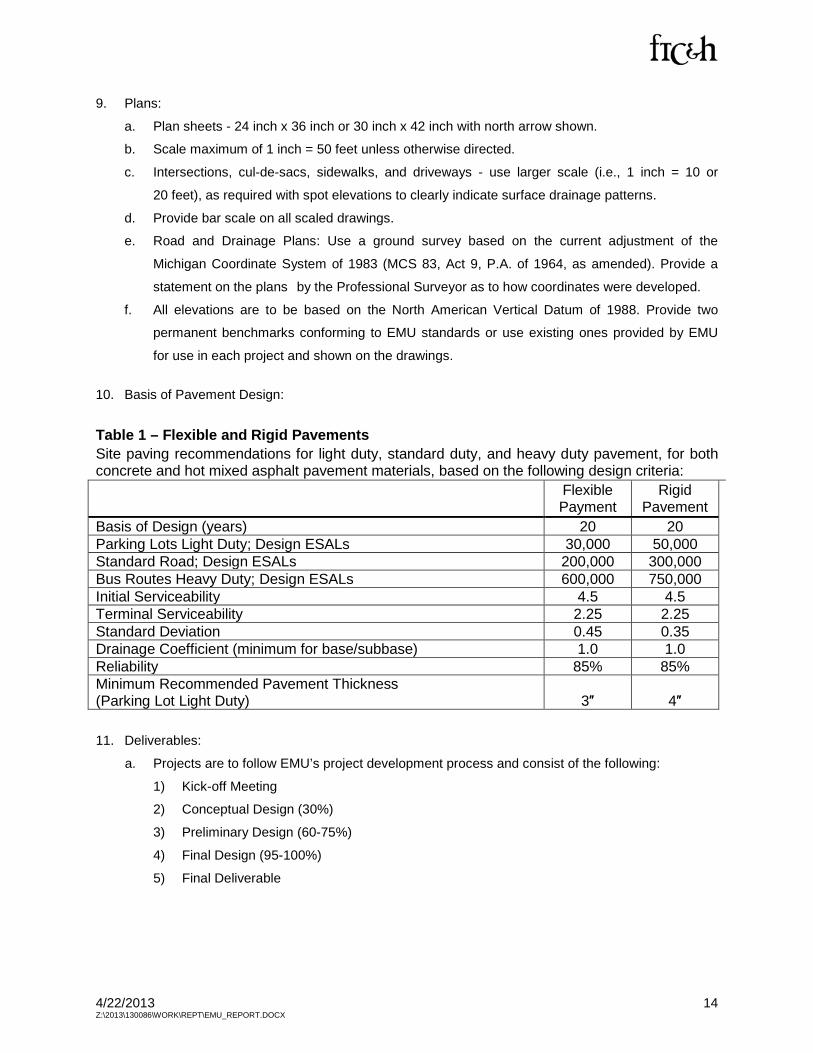
10. Basis of Pavement Design:
Table 1 – Flexible and Rigid Pavements Site paving recommendations for light duty, standard duty, and heavy duty pavement, for both concrete and hot mixed asphalt pavement materials, based on the following design criteria:
Flexible Payment
Rigid Pavement
Basis of Design (years) 20 20 Parking Lots Light Duty; Design ESALs 30,000 50,000 Standard Road; Design ESALs 200,000 300,000 Bus Routes Heavy Duty; Design ESALs 600,000 750,000 Initial Serviceability 4.5 4.5 Terminal Serviceability 2.25 2.25 Standard Deviation 0.45 0.35 Drainage Coefficient (minimum for base/subbase) 1.0 1.0 Reliability 85% 85% Minimum Recommended Pavement Thickness (Parking Lot Light Duty) 3″ 4″
11. Deliverables:
a. Projects are to follow EMU’s project development process and consist of the following:
1) Kick-off Meeting
2) Conceptual Design (30%)
3) Preliminary Design (60-75%)
4) Final Design (95-100%)
5) Final Deliverable
4/22/2013 15 Z:\2013\130086\WORK\REPT\EMU_REPORT.DOCX
12. Kick-off Meeting: The kick-off meeting will be held at EMU Physical Plant Building.
a. Review and finalize project scope.
b. Establish schedule for project completion.
c. Introduce team members and establish communication channels.
d. Obtain readily available data for project development.
13. Conceptual Design (30%) - The Conceptual Design Review will be held at EMU’s Physical Plant
Building. Provide a clearly defined conceptual design plan and present it in a form that results in
understanding and acceptance by EMU.
a. Existing conditions plan.
b. Conceptual site plan.
c. Recommended alternative solutions, if applicable.
d. Rough construction cost estimates.
14. Preliminary Design (60-75%) - The Preliminary Design Review will be held at EMU’s Physical Plant
Building. This meeting will include an onsite review. Preliminary designs are intended to advance
project concepts to a detailed understanding and quantification of all the major project elements.
a. Preliminary Plans.
b. Technical Specifications.
c. Updated Cost Estimate.
d. Include any field investigations.
e. Based on approved conceptual design and comments.
15. Final Design (95-100%) - The Final Design Review will be held at EMU’s Physical Plant Building.
The final project design will incorporate comments provided by EMU and other agencies regarding
the preliminary design submittal and onsite review. The final project design process converts the
preliminary design submittal (text and drawings, etc.) into a standalone and comprehensive set of
final design drawings (construction drawings) and technical specifications for project bidding
and construction.
a. Incorporate comments from preliminary design review meeting.
b. Final Design Drawings.
c. Technical Specifications.
d. Final Construction Quantities and Final Estimate of Costs.
e. Contract Bidding Documents and General Contract Conditions.
f. Construction permits, if required.
4/22/2013 16 Z:\2013\130086\WORK\REPT\EMU_REPORT.DOCX
16. Post-Construction Deliverable: “As-Built Drawings:”
a. Clearly document all changes made during construction to the project design in “As-built
drawings” modified by the engineer / designer after completion of construction.
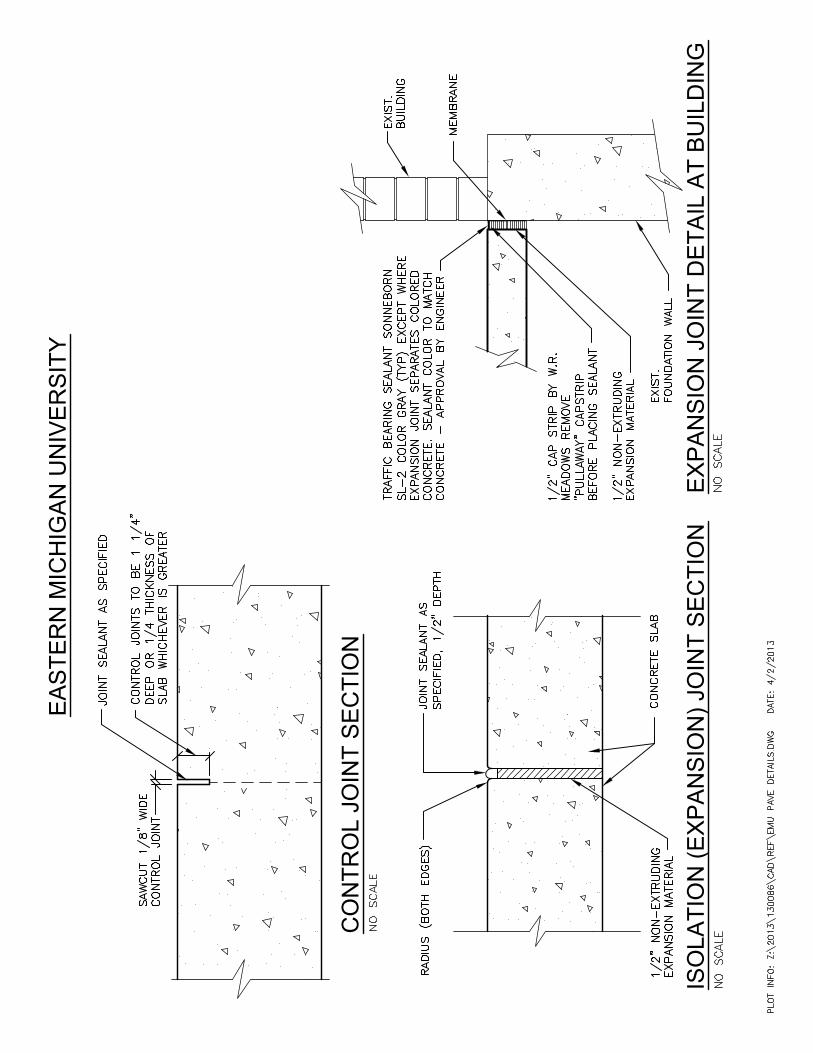
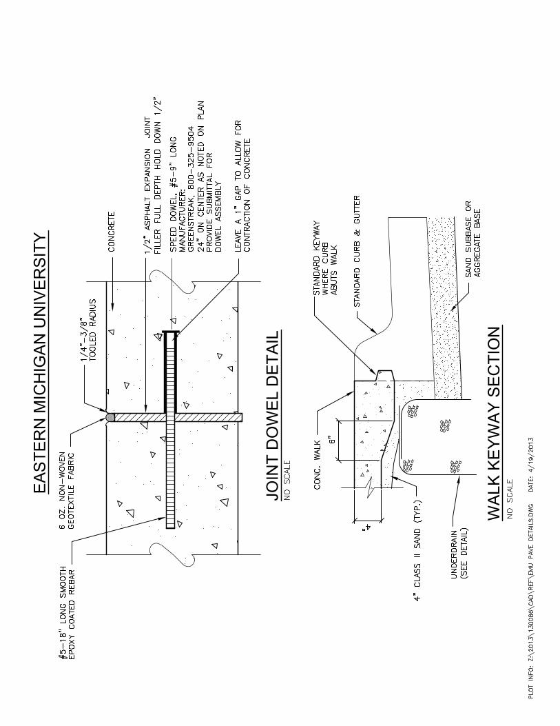
17. Standard Sections: See Appendix 2.

Appendix 1
Legend
Campus BoundaryNRCS Soil Survey
St- St. Clair Clay Loam
Bn- Boyer Loamy Sand
Bb- Blount Clay Loam
Fd- Fill Land
Sn- Sisson Sandy Clay Loam
Kn- Kibbie Sandy Loam, Clay Loam
Easte
rn M
ichiga
n Univ
ersity
Ypsila
nti, M
ichiga
nCa
mpus
SCS S
oil M
appin
g
G130086
1FIGURE NO.
PROJECT NO.
©Copyright 2013All Rights Reserved
PLOT INFO: Z:\2013\130086\CAD\GIS\Map Document\Soils.mxd Date: 3/5/2013 1:23:49 PM User: mb2
SOILS0 600300
FEETNORTH
engineers
architectsscientist
constructors
Hard copy isintended to be11"x17" when
plotted. Scale(s)indicated and
graphic quality maynot be accurate for
any other size.
fishbeck, thompson,carr & huber, inc.
Data Source: NRCS Web Soil Survey-Washtenaw County Version 11, 09/27/2012.
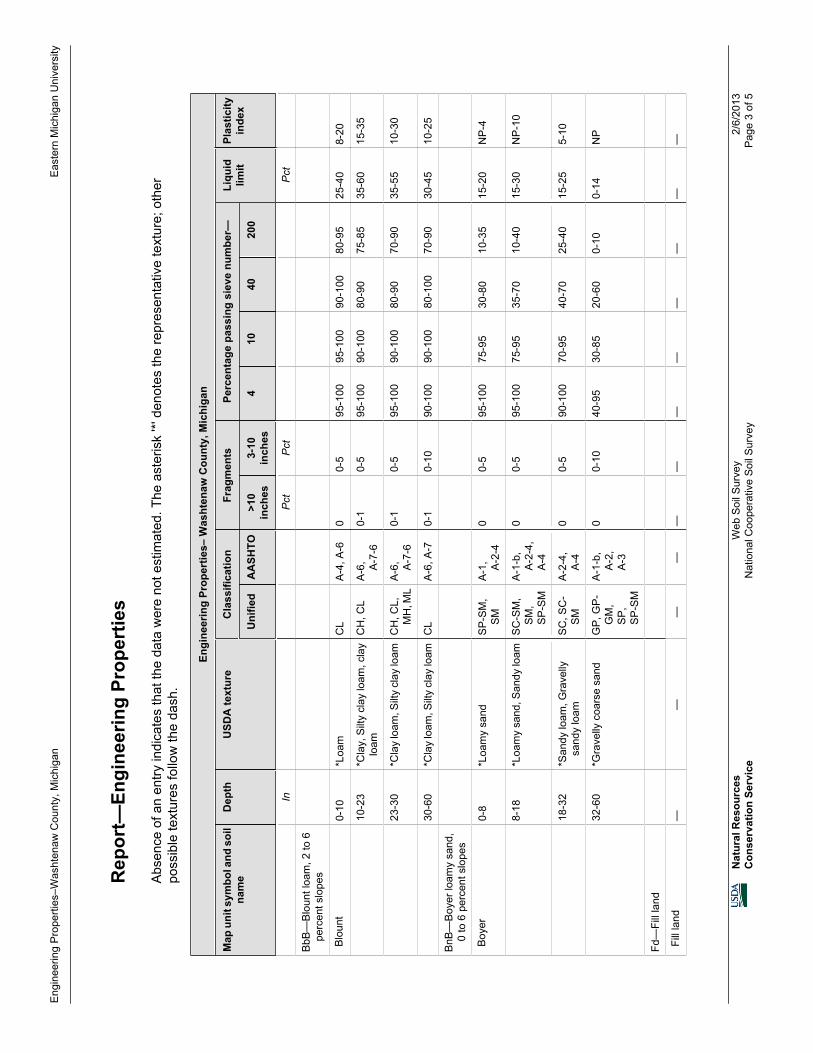
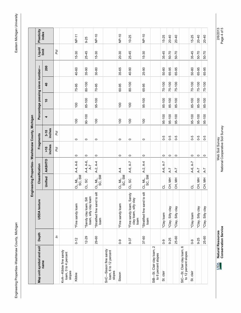
Report- Engineering Properties Washtenaw County, MichiganAbsence of an entity indicates that the data were not estimated." * " denotes the representative texture; other possible textures follow the dash.
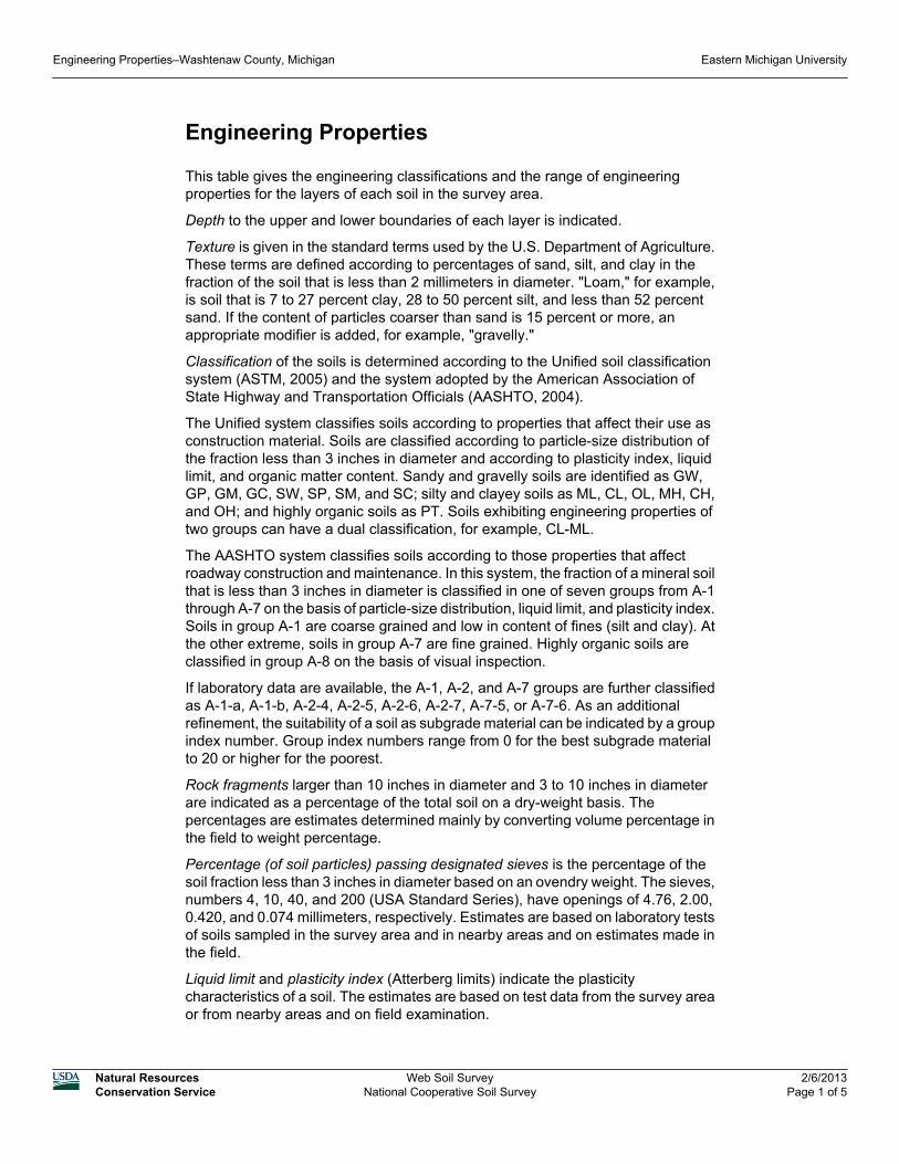
Engineering Properties
This table gives the engineering classifications and the range of engineeringproperties for the layers of each soil in the survey area.
Depth to the upper and lower boundaries of each layer is indicated.
Texture is given in the standard terms used by the U.S. Department of Agriculture.These terms are defined according to percentages of sand, silt, and clay in thefraction of the soil that is less than 2 millimeters in diameter. "Loam," for example,is soil that is 7 to 27 percent clay, 28 to 50 percent silt, and less than 52 percentsand. If the content of particles coarser than sand is 15 percent or more, anappropriate modifier is added, for example, "gravelly."
Classification of the soils is determined according to the Unified soil classificationsystem (ASTM, 2005) and the system adopted by the American Association ofState Highway and Transportation Officials (AASHTO, 2004).
The Unified system classifies soils according to properties that affect their use asconstruction material. Soils are classified according to particle-size distribution ofthe fraction less than 3 inches in diameter and according to plasticity index, liquidlimit, and organic matter content. Sandy and gravelly soils are identified as GW,GP, GM, GC, SW, SP, SM, and SC; silty and clayey soils as ML, CL, OL, MH, CH,and OH; and highly organic soils as PT. Soils exhibiting engineering properties oftwo groups can have a dual classification, for example, CL-ML.
The AASHTO system classifies soils according to those properties that affectroadway construction and maintenance. In this system, the fraction of a mineral soilthat is less than 3 inches in diameter is classified in one of seven groups from A-1through A-7 on the basis of particle-size distribution, liquid limit, and plasticity index.Soils in group A-1 are coarse grained and low in content of fines (silt and clay). Atthe other extreme, soils in group A-7 are fine grained. Highly organic soils areclassified in group A-8 on the basis of visual inspection.
If laboratory data are available, the A-1, A-2, and A-7 groups are further classifiedas A-1-a, A-1-b, A-2-4, A-2-5, A-2-6, A-2-7, A-7-5, or A-7-6. As an additionalrefinement, the suitability of a soil as subgrade material can be indicated by a groupindex number. Group index numbers range from 0 for the best subgrade materialto 20 or higher for the poorest.
Rock fragments larger than 10 inches in diameter and 3 to 10 inches in diameterare indicated as a percentage of the total soil on a dry-weight basis. Thepercentages are estimates determined mainly by converting volume percentage inthe field to weight percentage.
Percentage (of soil particles) passing designated sieves is the percentage of thesoil fraction less than 3 inches in diameter based on an ovendry weight. The sieves,numbers 4, 10, 40, and 200 (USA Standard Series), have openings of 4.76, 2.00,0.420, and 0.074 millimeters, respectively. Estimates are based on laboratory testsof soils sampled in the survey area and in nearby areas and on estimates made inthe field.
Liquid limit and plasticity index (Atterberg limits) indicate the plasticitycharacteristics of a soil. The estimates are based on test data from the survey areaor from nearby areas and on field examination.
Engineering Properties–Washtenaw County, Michigan Eastern Michigan University
Natural ResourcesConservation Service
Web Soil SurveyNational Cooperative Soil Survey
2/6/2013Page 1 of 5

References:American Association of State Highway and Transportation Officials (AASHTO).2004. Standard specifications for transportation materials and methods of samplingand testing. 24th edition.American Society for Testing and Materials (ASTM). 2005. Standard classificationof soils for engineering purposes. ASTM Standard D2487-00.
Engineering Properties–Washtenaw County, Michigan Eastern Michigan University
Natural ResourcesConservation Service
Web Soil SurveyNational Cooperative Soil Survey
2/6/2013Page 2 of 5
Rep
ort—
Engi
neer
ing
Prop
ertie
s
Abs
ence
of a
n en
try in
dica
tes
that
the
data
wer
e no
t est
imat
ed. T
he a
ster
isk
'*' d
enot
es th
e re
pres
enta
tive
text
ure;
oth
erpo
ssib
le te
xtur
es fo
llow
the
dash
.
Engi
neer
ing
Prop
ertie
s– W
asht
enaw
Cou
nty,
Mic
higa
n
Map
uni
t sym
bol a
nd s
oil
nam
eD
epth
USD
A te
xtur
eC
lass
ifica
tion
Frag
men
tsPe
rcen
tage
pas
sing
sie
ve n
umbe
r—Li
quid
limit
Plas
ticity
inde
xU
nifie
dA
ASH
TO>1
0in
ches
3-10
inch
es4
1040
200
InP
ctP
ctP
ct
BbB
—B
loun
t loa
m, 2
to 6
perc
ent s
lope
s
Blo
unt
0-10
*Loa
mC
LA
-4, A
-60
0-5
95-1
0095
-100
90-1
0080
-95
25-4
08-
20
10-2
3*C
lay,
Silt
y cl
ay lo
am, c
lay
loam
CH
, CL
A-6
, A-7
-60-
10-
595
-100
90-1
0080
-90
75-8
535
-60
15-3
5
23-3
0*C
lay
loam
, Silt
y cl
ay lo
amC
H, C
L,M
H, M
LA
-6, A-7
-60-
10-
595
-100
90-1
0080
-90
70-9
035
-55
10-3
0
30-6
0*C
lay
loam
, Silt
y cl
ay lo
amC
LA
-6, A
-70-
10-
1090
-100
90-1
0080
-100
70-9
030
-45
10-2
5
BnB
—B
oyer
loam
y sa
nd,
0 to
6 p
erce
nt s
lope
s
Boy
er0-
8*L
oam
y sa
ndS
P-S
M,
SM
A-1
, A-2
-40
0-5
95-1
0075
-95
30-8
010
-35
15-2
0N
P-4
8-18
*Loa
my
sand
, San
dy lo
amS
C-S
M,
SM
,S
P-S
M
A-1
-b,
A-2
-4,
A-4
00-
595
-100
75-9
535
-70
10-4
015
-30
NP
-10
18-3
2*S
andy
loam
, Gra
velly
sand
y lo
amS
C, S
C-
SM
A-2
-4,
A-4
00-
590
-100
70-9
540
-70
25-4
015
-25
5-10
32-6
0*G
rave
lly c
oars
e sa
ndG
P, G
P-
GM
,S
P,
SP
-SM
A-1
-b,
A-2
,A
-3
00-
1040
-95
30-8
520
-60
0-10
0-14
NP
Fd—
Fill
land
Fill
land
——
——
——
——
——
——
Eng
inee
ring
Pro
perti
es–W
asht
enaw
Cou
nty,
Mic
higa
nE
aste
rn M
ichi
gan
Uni
vers
ity
Nat
ural
Res
ourc
esC
onse
rvat
ion
Serv
ice
Web
Soi
l Sur
vey
Nat
iona
l Coo
pera
tive
Soi
l Sur
vey
2/6/
2013
Pag
e 3
of 5
Engi
neer
ing
Prop
ertie
s– W
asht
enaw
Cou
nty,
Mic
higa
n
Map
uni
t sym
bol a
nd s
oil
nam
eD
epth
USD
A te
xtur
eC
lass
ifica
tion
Frag
men
tsPe
rcen
tage
pas
sing
sie
ve n
umbe
r—Li
quid
limit
Plas
ticity
inde
xU
nifie
dA
ASH
TO>1
0in
ches
3-10
inch
es4
1040
200
InP
ctP
ctP
ct
KnA
—K
ibbi
e fin
e sa
ndy
loam
, 0 to
4 p
erce
ntsl
opes
Kib
bie
0-12
*Fin
e sa
ndy
loam
CL,
ML,
SC
, SM
A-4
, A-6
00
100
100
75-9
540
-60
15-3
0N
P-1
1
12-2
9*S
andy
cla
y lo
am, S
iltlo
am, s
ilty
clay
loam
CL,
SC
A-4
, A-6
,A
-70
090
-100
85-1
0080
-100
35-9
025
-45
9-25
29-6
0*S
tratif
ied
fine
sand
to s
iltlo
amC
L, M
L,S
C, S
MA
-2, A
-40
010
095
-100
70-9
530
-80
15-3
0N
P-1
0
SnC
—S
isso
n fin
e sa
ndy
loam
, 6 to
12
perc
ent
slop
es
Sis
son
0-9
*Fin
e sa
ndy
loam
CL,
ML,
SC
, SM
A-4
00
100
100
60-9
535
-65
20-3
0N
P-1
0
9-37
*Fin
e sa
ndy
loam
, San
dycl
ay lo
am, s
ilty
clay
loam
CL,
SC
A-6
, A-7
00
100
100
80-1
0040
-90
25-4
510
-25
37-6
0*S
tratif
ied
fine
sand
to s
iltlo
amC
L, M
L,S
C, S
MA
-2, A
-40
010
095
-100
65-9
525
-90
15-3
0N
P-1
0
StB
—S
t. C
lair
clay
loam
, 2to
6 p
erce
nt s
lope
s
St.
clai
r0-
9*C
lay
loam
CL
A-6
, A-7
00-
595
-100
85-1
0070
-100
50-8
035
-45
15-2
5
9-25
*Cla
y, S
ilty
clay
CH
, MH
A-7
00-
595
-100
85-1
0075
-100
65-9
550
-70
20-4
0
25-6
0*C
lay,
Silt
y cl
ayC
H, M
HA
-70
0-5
95-1
0085
-100
75-1
0065
-95
50-7
020
-40
StC
—S
t. C
lair
clay
loam
, 6to
12
perc
ent s
lope
s
St.
clai
r0-
9*C
lay
loam
CL
A-6
, A-7
00-
595
-100
85-1
0070
-100
50-8
035
-45
15-2
5
9-25
*Cla
y, S
ilty
clay
CH
, MH
A-7
00-
595
-100
85-1
0075
-100
65-9
550
-70
20-4
0
25-6
0*C
lay,
Silt
y cl
ayC
H, M
HA
-70
0-5
95-1
0085
-100
75-1
0065
-95
50-7
020
-40
Eng
inee
ring
Pro
perti
es–W
asht
enaw
Cou
nty,
Mic
higa
nE
aste
rn M
ichi
gan
Uni
vers
ity
Nat
ural
Res
ourc
esC
onse
rvat
ion
Serv
ice
Web
Soi
l Sur
vey
Nat
iona
l Coo
pera
tive
Soi
l Sur
vey
2/6/
2013
Pag
e 4
of 5

Dat
a So
urce
Info
rmat
ion
Soi
l Sur
vey
Are
a:
Was
hten
aw C
ount
y, M
ichi
gan
Sur
vey
Are
a D
ata:
V
ersi
on 1
1, S
ep 2
7, 2
012
Eng
inee
ring
Pro
perti
es–W
asht
enaw
Cou
nty,
Mic
higa
nE
aste
rn M
ichi
gan
Uni
vers
ity
Nat
ural
Res
ourc
esC
onse
rvat
ion
Serv
ice
Web
Soi
l Sur
vey
Nat
iona
l Coo
pera
tive
Soi
l Sur
vey
2/6/
2013
Pag
e 5
of 5

Appendix 2
EA
ST
ER
N M
IC
HIG
AN
U
NIV
ER
SIT
Y
CO
NT
RO
L JO
IN
T S
EC
TIO
N
IS
OL
AT
IO
N (E
XP
AN
SIO
N) JO
IN
T S
EC
TIO
NE
XP
AN
SIO
N JO
IN
T D
ET
AIL
A
T B
UIL
DIN
G
WA
LK
K
EY
WA
Y S
EC
TIO
N
JO
IN
T D
OW
EL
D
ET
AIL
EA
ST
ER
N M
IC
HIG
AN
U
NIV
ER
SIT
Y
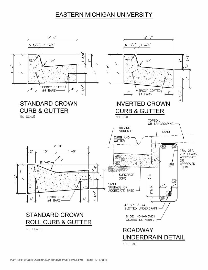
STANDARD CROWN
CURB & GUTTER
STANDARD CROWN
ROLL CURB & GUTTER
EASTERN MICHIGAN UNIVERSITY
ROADWAY
UNDERDRAIN DETAIL
INVERTED CROWN
CURB & GUTTER
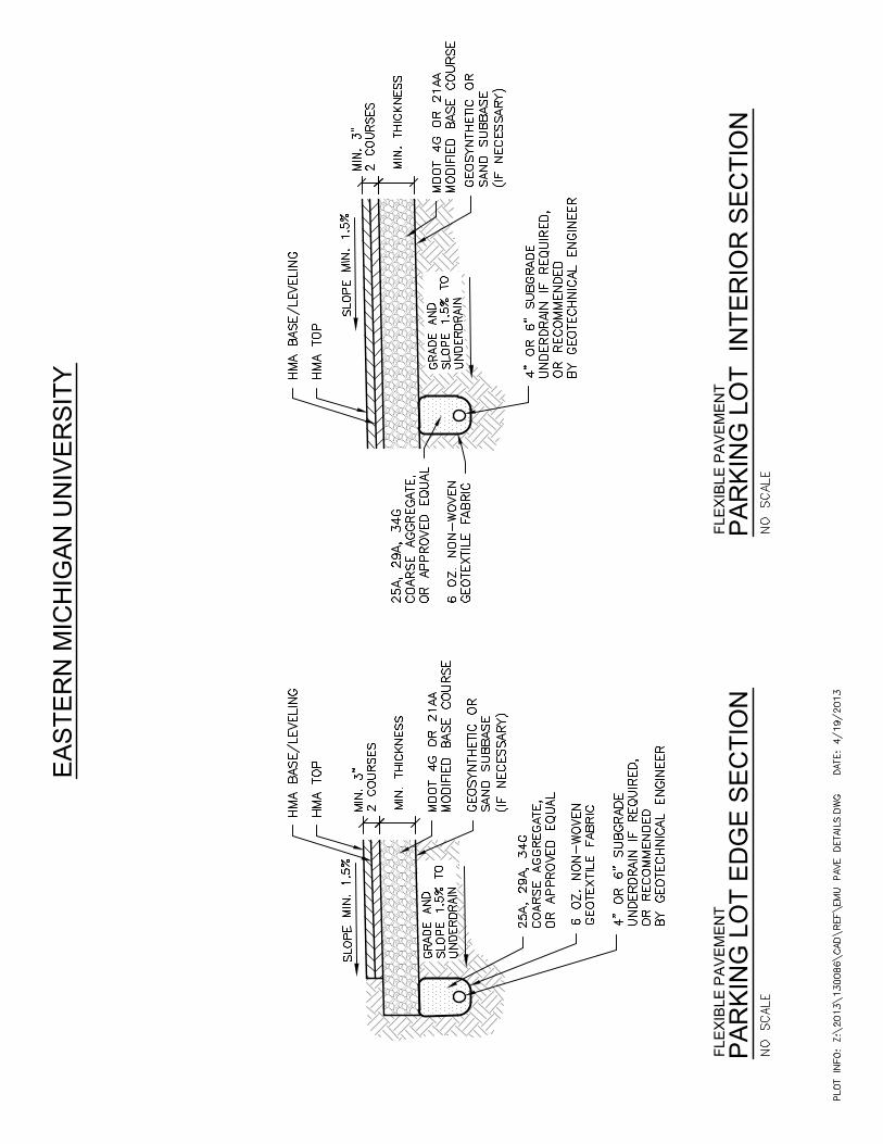
FLE
XIB
LE
P
AV
EM
EN
T
PA
RK
IN
G L
OT
IN
TE
RIO
R S
EC
TIO
N
EA
ST
ER
N M
IC
HIG
AN
U
NIV
ER
SIT
Y
FLE
XIB
LE
P
AV
EM
EN
T
PA
RK
IN
G L
OT
E
DG
E S
EC
TIO
N
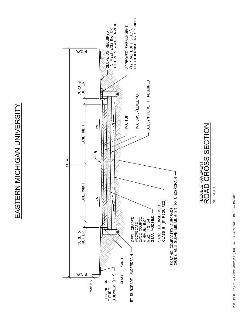
FLE
XIB
LE
P
AV
EM
EN
T
RO
AD
C
RO
SS
S
EC
TIO
N
EA
ST
ER
N M
IC
HIG
AN
U
NIV
ER
SIT
Y
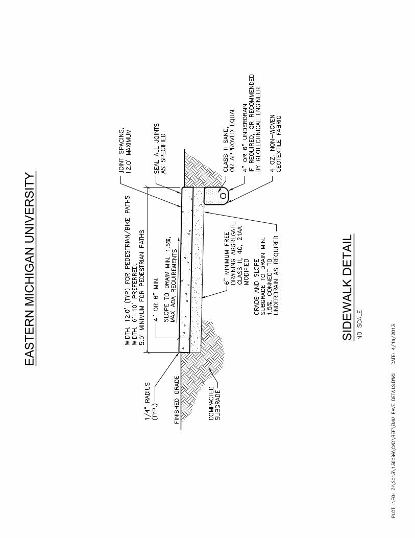
SID
EW
AL
K D
ET
AIL
EA
ST
ER
N M
IC
HIG
AN
U
NIV
ER
SIT
Y
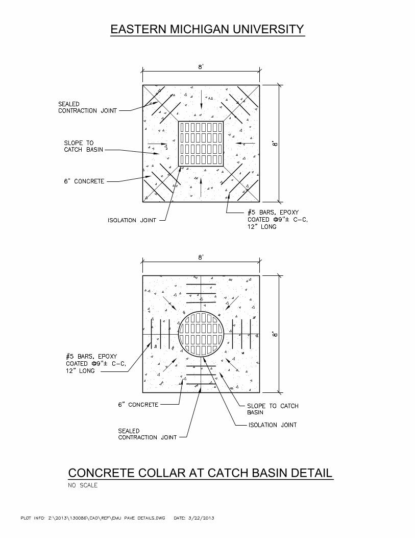
CONCRETE COLLAR AT CATCH BASIN DETAIL
EASTERN MICHIGAN UNIVERSITY
EASTERN MICHIGAN UNIVERSITY
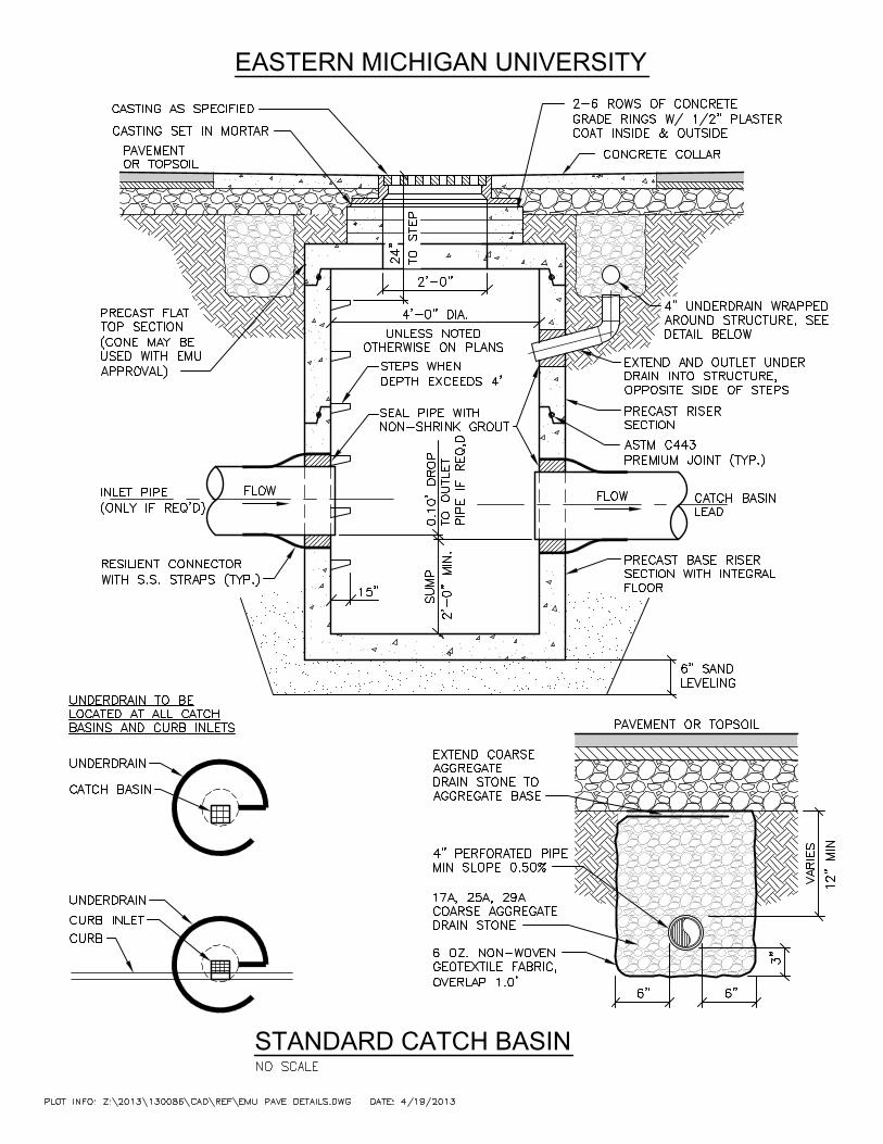
STANDARD CATCH BASIN