Embed Size (px)
Citation preview

7/23/2019 Earth Resistance Tester Manual
http://slidepdf.com/reader/full/earth-resistance-tester-manual 1/13
DIGITAL
EARTH
RESISTANCE
TESTER
INSTRUCTION
MANUAL

7/23/2019 Earth Resistance Tester Manual
http://slidepdf.com/reader/full/earth-resistance-tester-manual 2/13
NDEX
INTRODUCTION
AFETY
NOTES
FEATURES
SPECIFICATIONS
MEASURING
METHODS
MAINTENANCE
Page
I
1
2
3-4
5-7
8-9
l.INTRODUCTION
This
meter has
been
d
to
IEC
Publication
348
Electronic
Measuring
IEC/EN
61010-1
and
o
Follow
allwarnings
to
2.SAFETY
NOTES
.
Read
the
following
s
before
attempting
to
A
Warning
Risk
o
A
fi:iii:n
Rerer

7/23/2019 Earth Resistance Tester Manual
http://slidepdf.com/reader/full/earth-resistance-tester-manual 3/13
3.FEATURES
.
Capable
of
measuring
earth
voltage.
.
2mAmeasuring
cu
rrent
perm
its
earth
resistance
tests
with tripping
earth
leakage
current
breakers
in
the
circuit
under
test.
.
ln
addition
to
facilitating
for precision
measurement,
test leads
for simplified
two
wire
measuring
system
also
are
supplied
as
standard
Accessories.
.
0Q
adjustment.
o
Data
hold
function.
o
Battery
operated.
o
Battery life indicator.
.
Designed
to meet
IEC/EN
61010-1
safety
standard.
4.SPECIFICATION
.
Measurement
Syste
Earth
resistance
by
820Hz,2mA
approx.
o
Earth resistance
:
Range
|
20120012KO
Resolution
:
0-19.99o
(0.01o)
0-199.9f)
(0.1o)
0-1eeeo
(1o)
o
Earth voltage
:
0-20
.
Accuracy
:
Earth resistance
i
t(
is
Earth
voltage
:
t(1%
.
Display
:
LCD
3/,
digit(2000
c
.
Low
battery indicatio
"
ft
"
symbol appea
o
Data hold
indication
"
lHolpl
"
symbol appe
o
Over range
indicatio
'1 " (MSD).
.
Safety standard
:
lECi EN
61010-1, lns
2
7/23/2019 Earth Resistance Tester Manual
http://slidepdf.com/reader/full/earth-resistance-tester-manual 4/13
Power
source
:
1.5V
(ROP)
x 8
pieces
or
equivalent.
Dimensions
:
210(L)
x
210(W)
x 100(D)
mm.
Weight:
Approx.
13959 (battery included).
Accessories
:
Test
leads(red-1
5m,
yellow-1
0m,
green-Sm).
Auxiliary
earth
spikes.
Simplified
measurement
probe.
lnstruction manual.
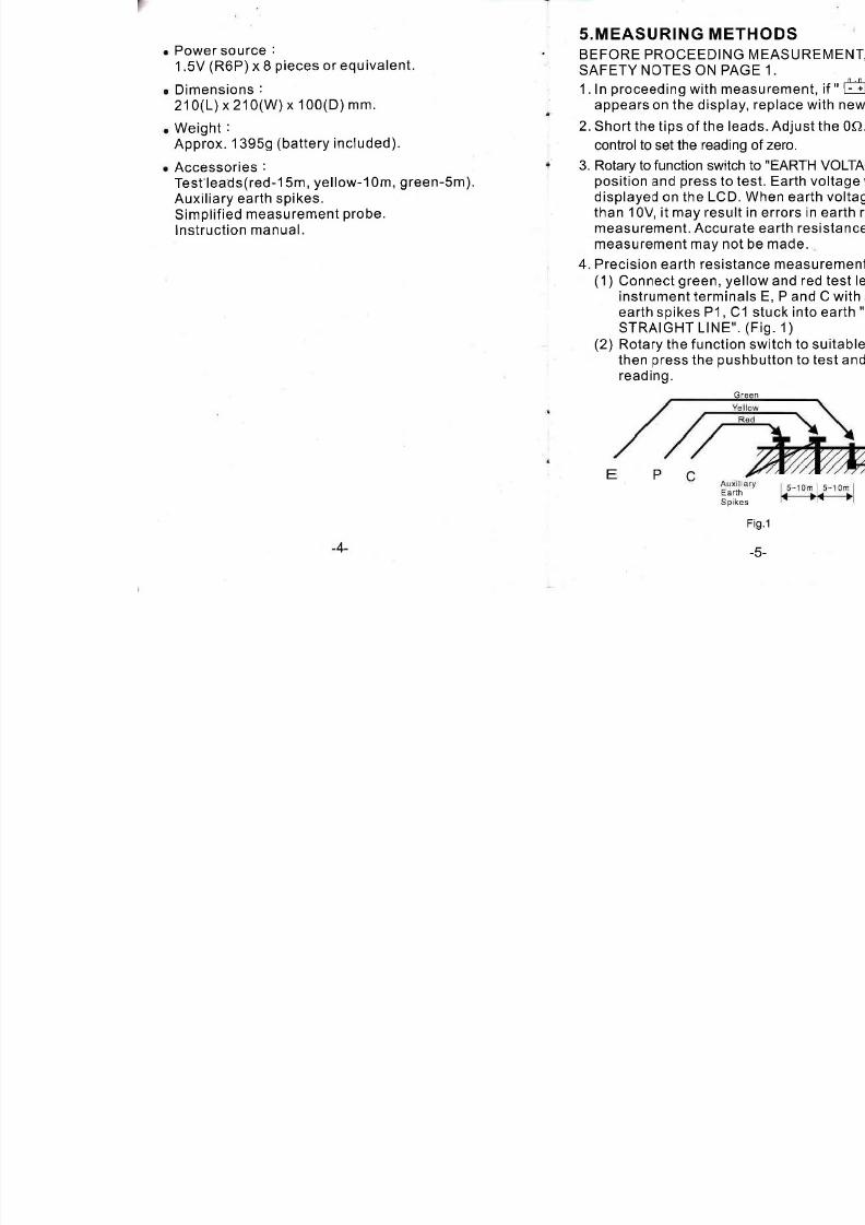
5.MEASURING ME
BEFORE PROCEEDIN
SAFETY
NOTES ON P
1. ln
proceeding
with m
appears
on
the displ
2.
Short
the
tips
of
the
control to set
the
read
3. Rotary
to
function swi
position
and
press
to
displayed
on
the
LC
than
10V, it may
res
measurement. Accu
measurement
may
n
4.
Precision
earth
resis
(1)
Connect
green,
instrument
termi
earth spikes
P1,
STRAIGHT LlNE
(2)
Rotary
the
functi
then
press
the
p
read ing.
4
E
S

7/23/2019 Earth Resistance Tester Manual
http://slidepdf.com/reader/full/earth-resistance-tester-manual 5/13
Simplified
earth resistance measurement
method
(1)
This method
is
recommended
where
an
earth
resistance higher
than
10Q is
measured
or
where it is not
possible
to drive auxiliary earth
spikes. An approximate value of earth
resistance can
be
obtained
by
the
two wire
system where
is
shown
in Fig.
2.
(2)
Rotary to function switch to
"EARTH
VOLTAGE.
position
and
press
to test. Make certain that
earth voltage
is
less than
10V.
(3)
First
rotary the function
switch
to
"200f)"
position
and
press
to test, read earth resistance.
lf the display shows
"1"
(MSD),
switch to
'2Kf)'
position
and
read earth resistance.
(a)
The reading obtained
(Rx)
is
an approximate
earth resistance value. There
is no need
for
external
shorting as P and C terminals are
shorted by using the test leads specified
for
the
Simplified measurement.
(5)
Rx
=
Re
-re
Rx
=
True Earth R
Re
=
lndicated
Va
re
=
Earth
Resista
(6)
Since measuring
earth leakage
bre
even
if
the earth s
supply with
an EL
*
Follow
the
proper
c
LED(red)
indicator
w
current
circulation
Ea
rth
Electrode
under tesl
Fig.2
-6-

7/23/2019 Earth Resistance Tester Manual
http://slidepdf.com/reader/full/earth-resistance-tester-manual 6/13

7/23/2019 Earth Resistance Tester Manual
http://slidepdf.com/reader/full/earth-resistance-tester-manual 7/13
ANA
EARTH
RESIS
I
.
I
L20
INSTRUCTIO

7/23/2019 Earth Resistance Tester Manual
http://slidepdf.com/reader/full/earth-resistance-tester-manual 8/13
INDEX
INTRODUCTION
SAFETY NOTES
FEATURES
SPECIFICATIONS
MEASURING
METHODS
MAINTENANCE
Page
10
10
11
12
13-15
16-17
l.INTRODUCTION
This meter has
been
d
accordance to the CE
Electronic
Measuring A
and other safety stand
ensure safe operation.
2.SAFETY NOTES
.
Read the following s
before
attempting
to
a
Meter
is
protect
insulation
or
rei
/\
Warnlng Risk
A
fi:iji:n
Refer

7/23/2019 Earth Resistance Tester Manual
http://slidepdf.com/reader/full/earth-resistance-tester-manual 9/13
.
Capable of
measuring
earth voltage.
.
2mA
measuring
current
permits
earth resistance
tests with tripping
earth leakage current
breakers
ln
the
circuit
under
test.
o
ln
addition to facilitating for
precision
measurement, test leads for
simplified two-wire
measuring system
also
are
supplied
as
standard
accessories.
o
Battery operated.
.
Battery life indicator.
.
Designed to meet
IEC
/
EN
61 01
0-1
safety
standard.
4.S
PEC IFICATIONS
.
Measurement
System
Earth
resistance
by
c
82OHz,2mA approx.
Earth voltage
by
rect
40-500H2
.
Ranges
and
Accurac
Earth resistance
121 1
Earth voltage
0-30VA
.
Safety standard
:
IEC/EN
61010-1,
lns
.
Power
source
:
1.5V
SUM-3(ROP)x
8
o
Dimensions
:
210(L)
.
Weight
:
Approx.
137
.
Accessories
:
Test
leads
(red-15M,
auxiliary earth spikes
probe,
instruction
ma
-11-

7/23/2019 Earth Resistance Tester Manual
http://slidepdf.com/reader/full/earth-resistance-tester-manual 10/13
5.MEASURING
METHODS
BEFORE
PROCEEDING MEASUREMENT, READ
SAFETY
NOTES
ON PAGE
1
O.
1.
Check
to
see
if the meter
pointer
is
adjusted
exactly
to the mechanical zero
position
of
the O
or
V
scale.
lf the
pointer
is in the zero
position,
turn
the zero adjust screw with a screwdriver.
2. Rotate
the function
switch
to
the
"BATT.
CHECK.
position
and
press
to test. Battery voltage is
sufficient when the meter
pointer
stays in
"OK"
position
of
the
battery check scale.
lf not, replace
with the new
batteries.
3.
Rotate the function switch to
"EARTH
VOLTAGE"
position
and
press
to
test.
Earth voltage will
be
indicated
on the
ACV scale. When the earth voltage
is more than
10V,
it may result in errors in earth
resistance
measurement.
Accurate
earth
resistance
measurement may not
be
made.
4. Precision earth resistance measurement method
:
(1)Connect green, yellow
and red test leads to
lnstrument
terminals
E, P
and C
with
auxiliary
earth spikes P1, C1 inserted into earth
"lN
A
STRAIGHT LlNE". (Fig.
3)
(2)Rotate
the function
switch
to
proper
range,
then
press
the
push-button
to
test
and
take the
reading.
5. Simplified
earth resis
(1)This
method is rec
resistance
higher t
where it is not
poss
earth spikes.
An a
resistance can
be
system
as
shown
i
(2)Rotate
the function
VOLTAGE"
positio
certain that earth
v
(3)First
rotate
the fun
and
press
to
test.
R
meter
pointer
indic
"x100"
position
an
(
)The reading obtain
earth
resistance
v
external
shorting s
shorted
by using
th
simplified
measure
Aux
Ear
Spik
-1
3-

7/23/2019 Earth Resistance Tester Manual
http://slidepdf.com/reader/full/earth-resistance-tester-manual 11/13
Green
-
Fig.4
(5)Rx=Re-re
Rx
=
True Earth
Resistance
Re
=
lndicated
Value
re
=
Earth Resistance
or Earth Electrode.
(6)Since
the measuring
current
is
as low
as
2mA,
the earth leakage breaker (ELCB)
does
not
trip
even
if
the earth side
of
the
commercial
power
supply with an ELCB
is used.
Press lamp
switch
to
turn
on
the lamp. The
lamp
will automatically
shut off
after
10
seconds.
Follow.the
proper
connection as
shown in Fig.
3.
The LED
(red)
indicatorwill
be lit. This
proves
that
a
correct
current
circulation
is under its
operation.
6.
MAINTENANCE
.
Battery
replacement
When setting
the fun
CHECK"
position
and
stay
in
"OK"
positio
Follows
:
(1)Disconnect
the
te
and
turn
off
the
Po
(2)Use
a
screwdriver
cover
then slide
a
the batteries
and
type
SUM-3(R6P)
(3)Place
back
cover
.
Cleaning
and
storag
-1
5-
Periodically
wipe
the
detergent.
Do
not
us
lf the meter
is
not
to
than
60
days,
remov
separately.

7/23/2019 Earth Resistance Tester Manual
http://slidepdf.com/reader/full/earth-resistance-tester-manual 12/13
CAT
IV -
ls
for measurements
performed
at the
source
of
.
the low-voltage
installation.
CAT
lll
-
ls for measurements
performed
in
the building
installation.
CAT
ll
-
ls for
measurements
performed
on circuits
directly
connected
to the low-voltage
installation.
CAT
I
-
ls for
measurements
perfonned
on circuits
not
.
directly
connected
to Mains.
Due to our
policy
of constant improvement
and developmenl, we reserue
the right
to change specifications
without notice.
-17-
7/23/2019 Earth Resistance Tester Manual
http://slidepdf.com/reader/full/earth-resistance-tester-manual 13/13
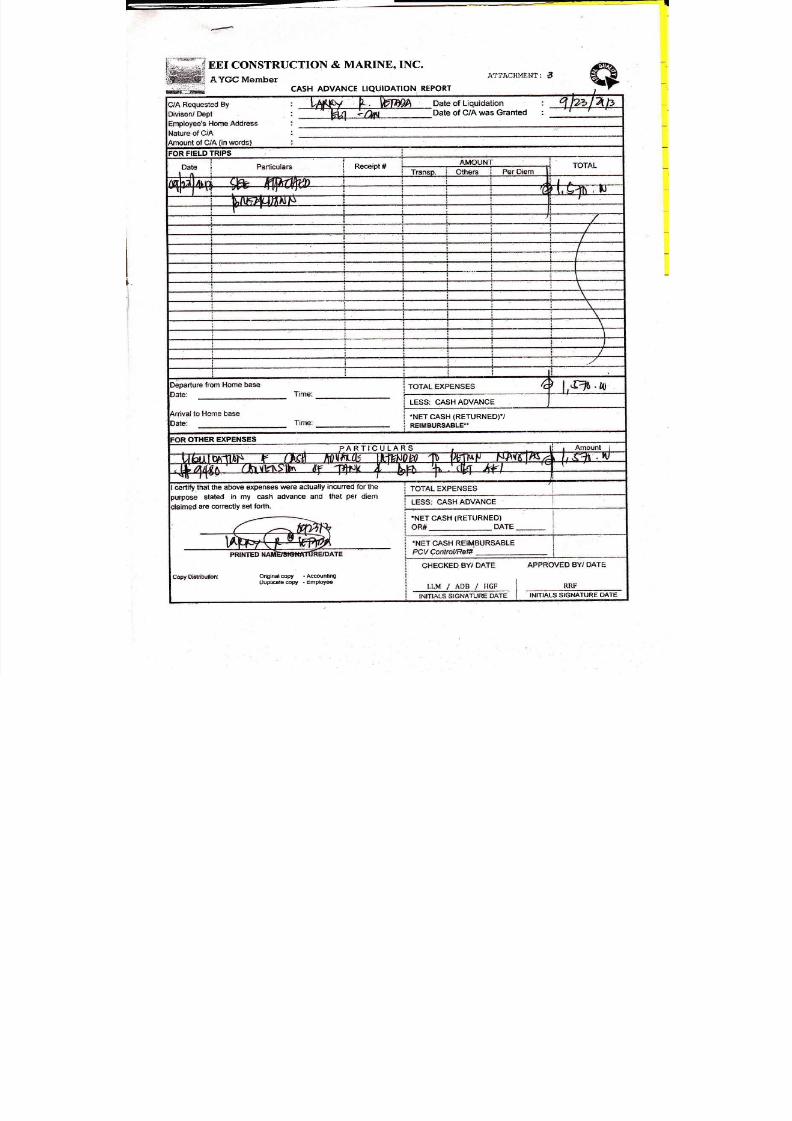
EEI CONSTRUCTION
& MARINE,
INC.
A
YGC
Member
CASH
ADVANCE
TIQUIDATION
REPORT
ATTACHMENT:
6
Date
of
C/A
was Granted
:
FIELD TRIPS
i
Receipt
LESS:
CASHADVANCE
i
-NETCASH
(RETURNEDT/
OTHER EXPENSES
ARTICULARS
certlry tnat the above expenses
were actually incurred
stated
in
my
cash
advance and
that
per
are correctly
set
forth,
Originalcopy
-Accounting
UuplEete
copy
-
Empbyee
INTTIALS SIGNATURE
DATE
'NET
CASH
(RETURNED)