Embed Size (px)
Citation preview

TR60
~fhDams Reservoirs
Technical Release No 60 210 - VI
Revised Oct 1985
US Department of Agriculture Soil Conservation Service Engineering Division
TECHNICAL RELEASE
NUMBER 60
CONTENTS
Title
Preface
iDefinitions
General 1 - 1
Dam Classification 1 - 1 Peak Breach Discharge Criteria 1 1 Utility Cables and Pipelines 1 - 3 Cut Slope Stability 1 - 3 Joint Use of Reservoir Capacity 1 - 3 Visual Resource Design 1 - 4 Safety and Protection 1 - 4 Water Supply Pipes 1 - 5 Streamflow Diversion During Construction 1 - 5 Reservoir Construction Storage 1 - 6
Hydrology 2 - 1
Precipitation and Runoff Amounts 2 - 1 Design Hydrographs 2 - 3 Dams in Series 2 - 3 Large Drainage Areas 2 - 4
Sedimentation 3 - 1
Geologic Investigations 4 - 1
Seismic Assessment 4 - 1 Subsidence 4 - 1 Emergency Spillways 4 - 1 Mass Movements 4 - 2 Karstic Areas 4 - 2 Multipurpose Dams 4 - 2 Other 4 - 2
Earth Embankments and Foundations 5 - 1
Height 5 - 1 Top Width 5 - 1 Embankment Slope Stability 5 - 2 Seepage 5 - 7 Zoning 5 - 7 Snrface Protection 5 - 7
i (210-VI-TR60 Oct 1985)--
CONTENTS PAGE 2
Title Page
Principal Spillways 6 - 1
Capacity of Prinipal Spillways 6 - 1 Elevation of Principal Spillways 6 - 2 Routing of Principal Spillway Hydrographs 6 - 2 Design of Principal Spillways 6 - 2
Emergency Spillways 7 - 1
Closed Type Spillways 7 - 1 Spillway Requirements 7 - 1 Vegetated and Earth Emergency Spillways 7 3 Rock Emergency Spillways 7 - 6 Structural Emergency Spillways 7 - 6
Figures 2-1 Principal Spillway Runoff Volumes - North Central and
Northeastern States
(A) 100-year 10-day Runoff (inches) 2 - 10 (B) Ratios of Volumes of Runoff CQ1Q10) middotmiddotmiddotmiddotmiddotmiddotmiddotmiddotmiddotmiddotmiddotmiddotmiddot 2 - 11 (C) Quick Return Flow (csm) 2 - 12
2-2 Principal Spillway Runoff Volumes in Snowmelt Producing Flood Areas - Northwestern States
(A) 100-year 10-day Runoff (inches) 2 - 13 (B) Ratios of Volumes of Runoff (Q1Q10) middotmiddotmiddotmiddotmiddotmiddotmiddotmiddotmiddotmiddot middotmiddotmiddotmiddot 2 - 14
2-3 Minimum 100-year Precipitation 6-hour-10 sq mi 2 - 15
2-4 Probable Maximum Precipitation 6-hour-10 sq mi 2 - 16
2-5 Probable Maximum Precipitation Study Regions 2 - 17
2-6 Emergency Spillway and Freeboard Volume Adjustments and Storm Distribution 2 - 18
4-1 Seismic Zone Map 4 - 3
7-1 Minimum Emergency Spillway Capacity 7 - 8
(210-VI-TR60 Oct 1985)
CONTENTS PAGE 3
Tables 2-1 National Weather Service Publications
Precipitation Data
2-2 Minimum Principal Spillway Hydrologic Criteria
2-3 Principal Spillway Volume Adjustments
2-4 Minimum Quick Return Flow for Principal Spillway Hydrographs
2-5 Minimum Emergency Spillway Hydrologic Criteria
5-1 Minimum Top Width of Embankment
5-2 Slope Stability Criteria for Dams
5-3 Nomenclature of Shear Strength Tests
7-1 Permissible Velocities for Vegetated Spillways
7-2 Permissible Canal Velocities After Aging
2
2
2
2
2
5
5
5
7
7
-
-
-
-
-
-
-
-
-
-
5
6
7
8
9
1
4
6
9
10
(210-VI-TR60 Oct 1985)
I
PREFACE
This Technical Release (TR) describes design procedures and provides minimum requirements for planning and designing earth dams and associated spillways This TR was developed to provide uniform criteria for earth dams and reservoirs SCS plans designs and constructs complex dams under widely varying conditions It is essential that these dams be constructed with uniform criteria to assure consistent performance As new experience materials and knowledge become available this document will be revised
This TR applies to all Class (a) dams with a product of storage times the effective height of the dam of 3000 or more those more than 35 feet in effective height and all Class (b) and (c) dams Requirements are stated as maximum or minimum limits and may not be satisfactory design criteria for all sites In some cases problems may arise where proven solutions are not ava~lable or alternative procedures may need to be evaluated before the best solutions can be developed and selected Experience state laws and regulations investigations analysis expected maintenance environmental considerations or safety laws may dictate more conservative criteria to insure satisfactory performance
This edition of the TR incorporates those revisions previously issued by changes on February 10 1982 June 2 1982 and April 6 1984 Also included are additions for peak breach discharge criteria streamflow diversion analysis conservation storage analysis updates on hydrometeorological report references and revision in embankment slope stability criteria
(210-VI-TR60 Oct 1985)
i
DEFINITIONS
Base flow is the sustained or fair-weather discharge which persists after storm runoff and associated quick return flow have been depleted It is usually derived from groundwater discharge or gradual snow or ice melt over extended periods of time but need not be continuous flow (It can be based on annual or seasonal periods depending upon when major floods usually occur)
Conservation storage is water impounded for consumptive uses such as municipal industrial and irrigation and non-consumptive uses such as recreation and fish and wildlife
The control section in an open channel spillway is that section where accelerated flow passes through critical depth
A dam is an artificial barrier together with any associated spillways and appurtenant works across a watercourse or natural drainage area which does or may impound or divert water
Design life is a period of time during which a dam is designed to perform its assigned functions satisfactorily~
A dry dam is a dam that has an ungated outlet positioned so that essenshytially all stored water will be drained from the reservoir by gravity The reservoir will normally be dry
An earth dam is a dam in which the principal barrier is an embankment of earth or rock fill or combination of earth and rock fill
An earth spillway is an open channel spillway in earth materials without vegetation
Economic life is the period of time during which economic benefits accrue to a dam
Effective height of dam is the difference in elevation in feet between the lowest open channel emergency spillway crest and the lowest point in the original cross section on the centerline of the dam If there is no open channel emergency spillway the top of the dam becomes the upper limit
The emergency spillway is the spillway designed to convey excess water through over or around a dam
The emergency spillway hydrograph is the hydrograph used to establish the dimensions of the emergency spillway
An emergency spillway system is a single emergency spillway or combination of emergency spillways designed to work togethr
(210-VI-TR60 Oct 1985)
ii
The exit channel of an open channel spillway is the portion downstream from the control section which conducts the flow to a point where it may be released without jeopardizing the dam
The freeboard hydrograph is the hydrograph used to establish the minimum settled elevation of the top of the dam It is also used to evaluate the structural integrity of the spillway system
The inlet channel of an open channel spillway is the portion upstream from the control section
Joint extensibility is the amount a pipe joint can be extended from the fully engaged position without losing strength or watertightness In case of rubbergasket joints it is measured from the center of the gasket to the point of flare of the bell ring or collar when the joint is fully closed
Joint gap is the longitudinal dimension between the end face of the spigot end of a pipe joint and the corresponding face of the bell end of the connecting pipe It does not include the beveled portion designed for sealing compounds
The joint use pool is the portion of a reservoir which serves two or more purposes for instance conservation storage and floodwater storage
A primary emergency spillway is the spillway with the lowest crest elevashytion in an emergency spillway system
The principal spillway is the lowest ungated spillway designed to convey water from the reservoir at predetermined release rates
The principal spillway hydrograph is the hydrograph used to determine the minimum crest elevation of the emergency spillway It is used to establish the principal spillway capacity and determine the associated minimum floodwater retarding storage
Quick return flow is the diminishing discharge directly associated with a specific storm that occurs after surface runoff has reached its maximum It includes base flow prompt subsurface discharge (commonly called interflow) and delayed surface runoff
A ramp spillway is a vegetated spillway constructed over an earth dam in a manner such that the spillway is a part of the embankment
The retarding pool is the portion of the reservoir allotted to the temshyporary impoundment of floodwater Its upper limit is the elevation of the crest of the emergency spillway
Retarding storage is the volume in the retarding pool
A rock spillway is an open channel spillway through competent non-erodible natural rock materials
(210-VI-TR60 Oct 1985)
iii
The sediment pool is the portion of the reservoir allotted to the accumulation of submerged sediment during the design life of the dam
The sediment pool elevation is the elevation of the surface of theI anticipated submerged sediment accumulation at the dam
Sediment storage is the reservoir capacity allocated to total sediment I (submerged and aerated) accumulation during the life of the dam
A spillway is an open or closed channel conduit or drop structure used to convey water from a reservoir It may contain gates either manually or automatically controlled to regulate the discharge of water
Storage is the capacity of the reservoir below the elevation of the crest of the emergency spillway
A vegetated spillway is a vegetated open channel spillway in earth materials
Visual Focal is an element in the landscape upon which the eyes automatically focus because the elements size form color or texture contrast clearly with its surroundings
middotmiddot~
(210-VI-TR60 Oct 1985)
1-1
General
Dam Classification
In determining dam classification a number of factors are to be considered Consideration is to be given to the damage that might occur to existing and future developments should the dam suddenly release large quantities of water downstream due to a breach failure r landslide into the reservoir The effect of failure on public confidence is an important factor State and local regulations and the responsibility of the involved public agencies are to be recognized The stability of the spillway materials the physical characteristics of the site and the valley downstream and the relationship of the site to industrial and residential areas including controls of future development all have a bearing on the amount of potential damage in the event of a failure
Dam classification is determined by the above conditions It is not determined by the criteria selected for design The policy on classification is in 210-V Part 520 Subpart C DAMS (National Engineering Manual)
Classes of Dams The following classes of dams have been established by policy and repeated here for convenience of the user
Class (a) --Dams located in rural or agricultural areas where failure may damage farm buildings agricultural land or township and country roads
Class (b) --Dams located in predominantly rural or agricultural areas where failure may damage isolated homes main highways or minor railroadE or cause interruption of use or service of relatively important public utilities
Class (c) --Dams located where failure may cause loss of life serious damage to homes industrial and commercial buildings important public utilities main highways or railroads
Peak Breach Discharge Criteria Breach routings are used to help delineate the area potentially impacted by inundation should a dam fail and can be used to aid dam classification
Stream routings made of the breach hydrograph are to be based upon topographic data and hydraulic methodologies mutually consistent in their accuracy and commensurate with the risk being evaluated
The minimum peak discharge of the breach hydrograph l regardless of the technique used to analyze the downstream inundation area is as follows
lf The breach hydrograph is the outflow hydrograph attributed to the sudden release of water in reservoir storage due to a dam breach
(210-VI-TR60 Revised Amend 1 Oct 1990)
1-2
1 For depth of water at the dam at the time of failure gt 103 feet
65 H 185Qmax V
2 For depth of water at the dam at the time of failure lt 103 feet
35Qmax 1100 Br 1middot bull
but is not to be less than
Qmax 32 12S
and need not exceed
Q 65 H 1 85 max middot-w
3 When the width of the valley L at the water surface elevation corresponding to the depth H is less than
65 u035 T
o416
replace the equation
in categories 1 and 2 above with the equation
Qmax 0416 L 11S Where
the peak breach discharge cfs
breach factor acre
Vs reservoir storage at the time of failure acre-feet
Rw depth of water at the dam at the time of failure however if the dam is overtopped depth is set equal to the height of dam feet
A cross-sectional area of embankment at the assumed location of breach usually the template section (normal to the dam longitudinal axis) at the general flood plain location sq ft
T theoretical breach width at the water surface elevation 1bull85corresponding to the depth H for the equation Qmax 65 tt
feet
L width of the valley at the water surface elevation corresponding to the depth llbull feet
(210-VI-TR60 Revised Amend 1 Oct 1990)
1-3
The peak discharge value determined by using principles of erosion hydraulics and sediment transport may be used in lieu of the peak discharge computed using the above equations
Utility Cables and Pipelines
Existing pipelines cables and conduits of a wide variety of sizes materials and functions are frequently encountered at dam sites These conduits are usually located at shallow depths in the flood plain They constitute a hazard to the safety of the dam and are to be (1) relocated away from the site or (2) reconstructed or modified to provide the durability strength and flexibility equal in all aspects to the principal spillway designed for the site in accordance with Service criteria and procedures Overhead cables or power lines are to be relocated or raised as necessary to prevent damage or hazard to the public
Every reasonable effort is to be made to have such conduits cables and pipelines removed from the site Most utilities and industries will want their facility removed from the site for easy maintenance Only as a last resort andunder the limitations imposed below are conduits to be permitted to remain under an earth dam embankment
Conduits permitted to remain under any part of the embankment below the crest of the emergency spillway are to be (1) provided with seepage control against I potential piping (2) properly articulated on all yielding foundations (3) encased in concrete or otherwise treated to insure durability and strength equal to that of the principal spillway and (4) made watertight against leaking either into or out of the pipe
Enclosure of the conduit cable or pipeline within another conduit which meets the requirements of this section and which is positively sealed at the upstream end to prevent seepage into the enclosing conduit is acceptable Such an enclosing conduit is to extend the full distance through which the conduit cable or pipeline being enclosed is beneath the embankment
Cut Slope Stability
Natural and excavation cut slopes are to be planned and formed in a stable and safe manner Spillways inlet and outlet channels borrow pits reservoir edges abutment areas and foundation excavations are all locations where these considerations are needed Field investigations methods of analysis design and construction requirements and resultant specifications are to recognize and provide for safe functional performance
Joint Use of Reservoir Capacity
A reservoir site may be used more efficiently where hydrologic conditions permit joint use of storage capacity by flood water and conservation storage The following requirements must be met for joint use storage dams
1 There is reasonable assurance that water will be available to meet objectives
(210-VI-TR60 Oct 1985)
1-4
2 Flood protection objectives of the project are satisfied
3 Spillway conditions are such that the dam will perform safely
Special hydrologic studies are to be made to show that the requirements can be met This may include hydrometeorologic instrumentation and analysis
Hydraulic features are to include an ungated spillway outlet at the top of the joint use pool A gated opening is to be provided at the bottom of the joint use pool adequate for use of the conservation storage and evacuation of J
the joint use pool
Provision are to be made for operation of the joint use pool to insure functioning of the dam as designed These are to include a competent operating and maintaining organization and a specific operation and maintenance plan These requirements are to be a part of the planning process and agreed to by the sponsors or owner
Visual Resource Design
The public generally prefers lake or waterscape scenery Therefore when permanent pools are created by dam construction they can enhance the visual resource if the water views are emphasized A visual design objective is to focus public views toward the permanent pool and reduce the visual focal effects of the structural elements
Visual focus on the lake is achieved by locating roads and walkways so that the entering or first perceptions of the site are of the waterscape scenery In most landscapes the lake will automatically predominate if other elements are visually designed to be subordinate
Borrow areas are to be shaped to blend with the surrounding topography These areas are to be revegetated with herbaceous and woody plants to visually fit the existing surrounding vegetation Fences are to be constructed parallel to the contour as much as possible be located behind existing vegetation as seen from the major view points and be placed low in the landscape Dams are to be shaped to blend with the natural topography to the extent feasible
Safety and Protection
Many dams are hazardous to the public Features designed for recreation or fish and wildlife are especially attractive to the public since they provide an opportunity to use the water All dams are to be designed to avoid hazardous conditions where possible Open-top risers steep-walled channels and chutes plunge pools and stilling basins are hazardous and require special attention All dams are to be provided with safety fences guard rails or other safeguards as necessary to protect the public and operation and maintenance personnel
The embankment and spillways are to be fenced where necessary to protect the dam from livestock and foot and vehicular traffic
(210-VI-TR60 Oct 1985)
1-5
Water Supply Pipes
Water supply pipes or conduits for other purposes installed under any part of the embankment below the crest of the emergency spillway are to (1) provide durability strength and flexibility equivalent to the principal spillway (2) be watertight against anticipated pressures (3) be adequate for their intended use and (4) be provided with seepage control against potential piping
Streamflow Diversion During Construction
Streamflow past the dam site unless controlled occurs at a somewhat random time with variable frequency of magnitudes A hazard exists during dam construction beginning when the embankment cofferdam or other ancillary structures obstruct the natural streamflow During construction a greater risk usually exists for some time period than after the dam is completed The risk is different for each dam because of the varying factors of construction time climate watershed size and diversion capacity An evaluation is to be made of the risk from embankment failure by overtopping and other similar hazards during construction The risk involved in overtopping during construction increases with the following factors
1 Dams of higher hazard class 2 Greater volume of reservoir storage 3 Dams with larger watersheds 4 Longer critical construction time periods 5 Smaller diversion release rates (less unit discharge per unit
watershed area)
The consequence of overtopping during construction may vary from a slight amount of erosion on a homogeneous clay dam to a breach of an embankment including loss of a temporary diversion coffer dam The erosion or breach causes increased inundation and sedimentation of downstream areas
The risk may be evaluated based upon experience of comparable dams constructed in the same hydrologic setting An evaluation may also be made using available streamflow records to obtain stage-duration-frequency information for a range of diversion rates Streamflow data should be used when available otherwise an evaluation may be made using climatalogical record data for generation of synthetic hydrographs to develop stageshyduration-frequency information for a range of diversion rates
The size of diversion is to be designed to provide an acceptable level of risk The probability required to protect against overtopping varies from 20 percent to 5 percent chance in any one year A 10 percent chance probability is frequently used when the critical construction period is limited to one construction season An alternative to a larger diversion capacity is to provide protection against erosion to the embankment surface (reinforcement) up to the desired elevation of acceptable risk
(210-VI-TR60 Qct 1985)
1-6
Reservoir Conservation Storage
Reservoirs with water stored for conservation purposes are to be analyzed using a water budget to determine a dependable water supply
For most purposes a dependable water supply is defined as one that is available at least 8 out of 10 years or has a probability of 80 percent chance in any one year A purpose such as municipal and industrial water may require a 95 percent chance probability of existing in any one year Other purposes such as recreation requires an analysis of the reservoir surface elevation fluctuation in order to evaluate the acceptable percent chance of occurrence
(210-Vl-TR60 Oct 1985)
2-1
HYDROLOGY
This section describes hydrologic criteria for determining spillway discharges and floodwater storage volumes Detailed procedures for developing principal spillway emergency spillway and freeboard hydrographs are contained in Chapter 21 Section 4 Hydrology of the SCS National Engineering Handbook (NEH-4) Methods of flood routing hydrographs through reservoirs and spillway systems are contained in Chapter 17 NEH-4 Special Studies as used in this text refer to all site specific studies with prior concurrence of selected procedures
Precipitation and Runoff Volumes
Principal Spillway Precipitation data are to be obtained from the most recent National Weather Service (NWS) reference which is applicable to the area under study Refershyences which contain precipitation data for return periods up to 100 years and for durations up to 10 days are listed in Sections A and B of Table 2-1
The return period for design precipitation amounts is dependent on the dam classification purpose size location and type of emergency spillway Minimum return periods are shown in Table 2-2 The minimum allowable areal adjustment ratios for 1 and 10-day precipitation amounts are tabulated in Table 2-3 part A
A storm duration of not less than 10 days is to be used for sizing the principal spillway The procedure in Chapter 21 NEH-4 for developing the storm distribution uses both the 1-day and 10-day runoff volumes
The procedure for estimating runoff volumes is to be selected based on which one requires the higher emergency spillway crest elevation when the principal spillway hydrograph is routed through the structure Procedures to be used to estimate runoff volumes include
(1) The runoff curve number (CN) procedure described in NEH-4 Use average antecedent moisture conditions (AMC II) or greater unless a special study shows that a different condition is justified The CN adjustment for a 10-day storm is estimated from Table 2-3 part B
(2) Runoff volumes from Figures 2-1 (A) and (B) or Figures 2-2 (A) and (B)
A special study may show that local streamflow records can be used directly or regionalized to develop design runoff volumes
Transmission losses reducing the runoff volume in arid and semiarid climatic areas may be used if the climatic index as defined in Chapter 21 NEH is less than one If transmission losses appear to be significant even though the climatic index is one or more such as in cavernous areas special studies are required
(210-VI-TR60 Oct 1985)
2-2
Obtain quick return flow from the map Figure 2-l(C) or Table 2-4 as appropriate
Emergency Spillway and Freeboard Table 2-5 establishes the minimum design precipitation amounts by dam class The most recent NWS references are to be used to estimate preshycipitation amounts in all areas The references are listed in Sections A and C of Table 2-1 The generalized maps Figures 2-3 and 2-4 can be used to establish the 10-square mile 100-year and the probable maximum precipitation (PMP) for the 37 contiguous states east of the 103rd meridian Figure 2-5 shows the location in which the NWS references for PMP are applicable
Areal adjustment and storm distribution factors contained in the NWS references listed on Figure 2-5 are to be used in their respective regions For areas not covered by an NWS publication minimum areal adjustment ratios for design precipitation amounts are shown on Graph A Figure 2-6 No areal adjustments are to be made for areas less than 10 square miles
The minimum storm duration to be used is 6-hours If the time of concentration (Tc) exceeds 6-hours the minimum design storm duration is to be equal to the Tc When the Tc exceeds 6-hours the precipitation amounts must be increased by the values in the applicable NWS references (Figure 2-S) The duration adjustment shown on Graph B Figure 2-6 may be used in areas where the NWS references are not applicable
For those locations where NWS references provide estimates of local storm (thunderstorm) and general storm PMP values the storm duration and distribution that result in the maximum reservoir stage when the hydrograph is routed through the structure should be used Unless a specific distribution is recommended in a NWS reference the distribution of precipitation with time should be approximately the same as that shown in Graph C Figure 2-6 For longer duration storms recommended distributions from NWS references should be used
The runoff curve number (CN) procedure in NEH-4 is used to determine runoff volumes using AMC II or greater The CN applies throughout the design storm regardless of the storm duration
The NWS may be requested to make special PMP studies for any location This includes but is not limited to drainage areas larger than 100 square miles areas of significant variation in elevation or areas located at the boundary of two studies where discontinuities in published values occur
(210-VI-TR60 Oct 1985)
2-3
Design Hydrographs
Principal Spillway Hydrographs Procedures in Chapters 16 and 21 NEH-4 and applicable national computer programs are to be used to develop the principal spillway hydrograph using precipitation and runoff amounts as described in the preceding section
When the area above a proposed dam is hydrologically complex the area should be divided into two or more hydrologically homogeneous subbasins for developing the design hydrograph
Streamflow records may be used to develop the principal spillway hydrograph where a special study shows they are adequate for this purpose
Emergency Spillway amp Freeboard Hydrographs Procedures in Chapters 16 and 21 NEH-4 and applicable national computer programs are to be used to develop emergency spillway and f reeboard hydrographs using precipitation and runoff amounts and subbasins if necessary as described in the preceding sections
Dams in Series
Upper Dam The hydrologic criteria and procedures for the design of an upper dam in a system of dams in series are to be the same as or more conservative than those for dams downstream if failure of the upper dam could contribute to failure of the lower dam The dam breach criteria contained on page 1-1 will be used to develop the breach hydrograph peak discharge
Lower Dam For the design of a lower dam hydrographs are to be developed for the areas controlled by the upper dams based on the same hydrologic criteria as the lower dam The hydrographs are routed through the spillways of the upstream dams and the outflows routed to the lower dam where they are combined with the hydrograph from the intermediate uncontrolled drainage area The combined principal spillway hydrograph is used to determine the capacity of the principal spillway and the floodwater retarding storage requirement for the lower site The combined emergency spillway hydrograph and the combined freeboard hydrograph are used to determine the size of the emergency spillway and the height of dam at the lower site
If upon routing a hydrograph through the upper dam the dam is overtopped or its safety is questionable it is to be considered breached For design of the lower dam the breach hydrograph is to be routed downstream to the lower dam and combined with the uncontrolled area hydrograph
In design of the lower dam the time of concentration (Tc) of the watershed above an upper dam is used to develop the hydrographs for the upper dam The Tc of the uncontrolled area above the lower site is used to develop the uncontrolled area hydrographs If the Tc for the total area exceeds 6-hours
(210-VI-TR60 Oct 1985)
2-4
the precipitation amounts for the emergency spillway and freeboard hydrographs must be increased by the values in the applicable NWS references (Figure 2-5)
The minimum precipitation amounts for each of the required hydrographs may be reduced by the areal reduction factor for the total drainage area of the dam system
Large Drainage Areas
When the area above a proposed dam approaches 50 square miles it is desirable to divide the area into hydrologically homogeneous subbasins for developing the design hydrographs Generally the drainage area for a subbasin should not exceed 20 square miles Watershed modeling computer programs such as the SCS Technical Release 20-Project Formulation-Hydrology or DAMS2-Structure Site Analysis may be used for inflow hydrograph development
If the Tc for the entire drainage area is greater than 6 hours storm durations longer than the Tc should be tested to determine the duration that gives the maximum reservoir stage for the routed emergency spillway and freeboard hydrographs
Precipitation amounts may exhibit marked variation in a large watershed This variation is based upon topographical and meteorological parameters such as aspect orientation mean elevation of subbasin and storm orientation Consideration is to be given to having the NWS make a special PMP study for large watersheds with drainage areas more than 100-square miles Individual watershed PMP studies can take into account orographic features that are smoothed in the generalized precipitation studies A special study also may be warranted in areas where significant snow melt can occur during the design storms
Studies to make use of available stream flow records are encouraged for purposes such as unit hydrograph development watetshed storage and timing effects and calibration of watershed models
(210-Vl-TR60 Oct 1985)
2-5
TABLE 2-1
NATIONAL WEATHER SERVICE REFERENCES - PRECIPITATION DATA
A Durations to 1 day and return periods to 100 years Technical Memorandum HYDR0-35 Durations 5 to 60 minutes for the
eastern and central states (1977) Technical Paper 40 48 contiguous states (1961)
(Use for 37 contiguous states east of the 105th meridian) Technical Paper 42 Puerto Rico and Virgin Islands (1961) Technical Paper 43 Hawaii (1962) Technical Paper 47 Alaska (1963) NOAA Atlas 2 Precipitation Atlas of the Western United States (1973)
Vol 1 Montana Vol II Wyoming Vol III Colorado Vol IV New Mexico Vol V Idaho Vol VI Utah Vol VII Nevada Vol VIII Arizona Vol IX Washington Vol X Oregon Vol XI California
B Durations from 2 to 10 da s and return eriods to 100 years Technical Paper 49 48 contiguous states (1964
(Use SCS West National Technical Center Technical Note shyHydrology - P0-6 Rev 1973 for states covered by NOAA Atlas 2)
Technical paper 51 Hawaii (1965) Technical paper 52 Asaska (1965) Technical paper 53 Puerto Rico and Virgin Islands (1965)
C Probable maximum precipitation (PMP) (See Figure 2-5) Hydrometeorological Report 36 California Pacific drainage (1961) Hydrometeorological Report 39 Hawaii (1963)
(PMP maps in TP-43 are based on HMR-39) Hydrometeorological Report 43 Northwest states Pacific drainage
(Rev 1981) Hydrometeorological Report 49 Colorado River and Great Basin
Drainages (1977) Hydrometeorological Report 51 For 37 contiguous states east of the
103rd meridian (1978) Hydrometeorological Report 52 Application of PMP estimates
states east of the 105th meridian (1982) Hydrometeorological Report 53 Seasonal variation of 10 square-mile
PMP estimates states east of the 105th meridian (1980) Hydrometeorological Report 54 PMP and snowmelt criteria for southeast
Alaska (1983) Hydrometeorological Report 55 Between the Continental Divide and the
103rd meridian (1984) Technical Paper 42gtdlt Puerto Rico and Virgin Islands (1961) Technical Paper 47 Jdlt Alaska (1963) New studies are in progress in the Tennessee River Watershed
National Weather Service National Oceanic and Atmospheric Administration (NOAA) US Department of Commerce formerly US Weather Bureau
degTechnical papers listed in both A and C
(210-VI-TR60 Oct 1985)
--
I
TABLE 2-2
MINIMUM PRINCIPAL SPILLWAY HYDROLOGIC CRITERIA N
Class Purpose of of
Dam Dam
~
N single --2
~
0 irrigation
lt1 I only
H I
l (a)
deg 0 single
0 or rt multiple shy() 41
(b) single or multiple
(c) single or multiple
Product of Storage x
Effective Height
less than 30000
greater than 30000
less than 30000
greater than 30000
all
all
all
Existing or Planned
Upstream Dams
none
none
any 2_
none or any
none or any
deg
Precipitation Data for Maximum Frequency 1 of Use of Emergency Spillway Types
Earth
12 design life
34 design life
Pso
12 (Pso + plOO)
PlOO
plOO
plOO
Vegetated
12 design life
34 design life
p25 11
12 (P2s + Psol
Pso
Pso
plOO
ll Precipitation amounts by return periods in years In some areas direct runoff amounts determined by figure 2-1 and 2-2 or procedures in Chapter 21 NEH-4 should be used in lieu of precipitation data
1_ Applies to irrigation dams on ephemeral streams in areas where the annual rainfall is less than 25 inches ]_ The minimum criteria are to be increased from P to P for a ramp spillway
25 100 ii Class (a) dams involving industrial or municipal water are to be designed with a minimum criteria equivshy
alent to that of class (b)
_ Applies when the upstream dam is located so that its failure could endanger the lower dam
l
2-7 TABLE 2-3
PRINCIPAL SPILLWAY VOLUME ADJUSTMENTS
A Minimum Areal Adjustment Ratios for Precipitation
Area AreaPoint Ratio for Area AreaPoint Ratio for Sq Mi 1 Day 10 Days Sq Mi 1 Day 10 Days
10 or less 1000 1000 45 0951 0976 15 0977 0991 50 0948 0974 20 0969 0987 60 0944 0972 25 0965 0983 70 0940 0970 30 0961 0981 80 0937 0969 35 0957 0979 90 0935 0967 40 0954 0977 100 0932 0966
B Ten-Day Runoff Curve Number Adjustment
Runoff Curve Numbers for
1 Day 10 Days 1 Day 10 Days 1 Day 10 Days 100 100 80 65 60 41
99 98 79 64 59 40 98 96 78 62 58 39 97 94 77 61 57 38 96 92 76 60 56 37 95 90 75 58 55 36 94 88 74 57 54 35 93 86 73 56 53 34 92 84 72 54 52 33 91 82 71 53 51 33 90 81 70 52 50 32 89 79 69 51 49 31 88 77 68 so 48 30 87 76 67 49 47 29 86 74 66 47 46 28 85 72 65 46 45 28 84 71 64 45 44 27 83 69 63 44 43 26 82 68 62 43 42 25 81 66 61 42 41 24
~This Table is used only if the 100-year frequency 10-day point rainfall is 6 or more inches If it is less the 10-day CN is the same as that for the 1-day CN
(210-VI-TR60 Oct 1985)
2-8
TABLE 2-4
MINIMUM QUICK RETURN FLOW FOR PRINCIPAL SPILLWAY HYDROGRAPHS
Ci QRF Ci
inday csm inday
100 00 00 150 0233 102 0011 030 152 0239 104 0022 060 154 0244 106 0033 090 156 0249 108 0045 120 158 0254
110 0056 150 160 0259 112 0067 180 165 0270 114 0078 210 1 70 0280 116 0089 240 l 75 0290 118 0100 270 180 0299
120 0112 300 185 0309 122 0122 329 1 90 0318 124 0133 358 195 0326 126 0144 386 200 0335 128 0153 412 205 0343
130 0163 437 210 - 0351 132 0171 461 220 0367 134 0180 483 230 0382 136 0188 505 240 0396 138 0195 525 250 o410
140 0202 544 260 0423 142 0209 563 270 o436 1 44 0216 580 280 0449 146 0222 597 290 0461 148 0228 613 3 00 -ki 0473
Change in tabulation interval For Ci greater than 3 use
5QRF(csm) =9 (Ci - 1) 0 middot QRF(inday) = QRF(csm) x 0037191
where QRF =quick return flow csm =cubic feet per second per square mile Ci = climatic index
QRF
csm
628 642 656 670 683
695 726 753 779 805
830 854 8 77 900 922
944 986
1026 1065 1102
1138 11 73 1207 1241 1273
(210-VI-TR60 Oct 1985)
( (
TABLE 2-5
MINIMUM EMERGENCY SPILLWAY HYDROLOGIC CRITERIA
Class Product Existing PreciPitation Data for Y of of or Planned Emergency
Dam Storage x Upstream Spillway Freeboard 0 Effective Height Dams Hydrograph Hydrograph lt
H
l less than 30000 none Piao plOO + 012 (PMP - plOO) 0
(a) Jj greater than 30000 none plOO + 006 (PMP - PlOO) plOO + 026 (PMP - plOO)
all any 1 plOO + 012 (PMP - plOO) plOO + 040 (PMP - PlOO)
none (b) all or plOO + Ol2 (PMP - PlOO) PlOO + 040 (PMP - plOO)
any
none0
ct (c) all or plOO + 0bull26 (PMP - PlOO) PMP any
3 _ = Precipitation for 100-year return period PMP = Probable maximum precipitationP100
3 Dams involving industrial or municipal water are to use minimum criteria equivalent to that of class (b) N I
1 Applies when the upstream dam is located so that its failure could endanger the lower dam
~
IgtI-
lt 0
d Hbull
deg0
~
iamp I-
0
rT
I-
~
degdeg0
(_
- bulloobull 9i 90deg osmiddot ~middot
Area I I i Area 2I
0
85
1
- middot 85 I tf~fo
_
middotI
Area 1 Area 2
40bull__
RATIOS FOR 50 AND 25-YEAR 10-DAY RUNOFF VOLUMES
To obtain Multiply map values byArea 1 Area 2 Area 3
50-YEAR 10-DAY RUNOFF 085 090 092 25-YEAA 10-DAY RUNOFF 070 080 085 Area 3
FIGURE 2middot1 (A) lOOmiddotYEAR 10-DAY RUNOFF (INCHES) PRINCIPAL SPILLWAY HYDROGRAPH
JANUARY 1971 REV APRIL 1976 OCTOBER 1990
l (_
( ( (
0
rt
LEGEND
0 1 - 1-Day Volume Runoff
010- 10-Day Volume Runoff
FIGURE 2-1 (B)
RATIOS OF VOLUMES OF RUNOFF (Q 11Q
10)
PRINCIPAL SPILLWAY HYDROGRAPH
JANUARY 1971 REV APRIL 1976
~
shybullOO ~middotmiddot cbull I I deg
IF~ R lt bull
middot~10
~
I Ngt-gt0I
Hlt I I -middot --~~---CUI V-lf-IJ-H
deg~
0
2
R i
rt I3 4
gt-gt
degln ~
Note For Wisconsin Michigan and eastern I
Iowa use csrn values in circles
FIGURE 2middot1 (C) QUICK RETURN FLOW (csm)
PRINCIPAL SPILLWAY HYDROGRAPH
JANUARY 1971 REV APRIL 1976
(_ ( (
( ( (
115deg r
---------~
~
N 0 I
ltl ----- --- H I
H ~ ashy0 I 40deg-_
0 ()
rt
00
~
-------middot-middot40
LEGEND
JltUgtj Pr1mar1ly snowmelt produced floods
CJ Primarily rain produced floods
[=J Deep snowpack areas
FIGURE 2-2 (A)50-YEAR 10-DAY RUNOFF-Use 85 of map value
25middotYEAR IO-DAY RUNOFF-Use 70 of map value 100-YEAR 10-DAY RUNOFF (INCHES)
PRINCIPAL SPILLWAY HYDROGRAPH SNOWMELT PRODUCING FLOOD AREAS ~
January 1971 Rev Apri I 1976 w
I
0(lrt
_ --1()LEGEND
[j Primarily snowmelt produced floods
LJ Primarily rain produced floods
C=J Deep snowpack areas
Q1 - I-Day Volume RunoffQ10 - 10-0ay Volume Runoff FIGURE 2-2 (B)
RATIOS OF VOLUMES OF RUNOFF (Q 1Q10)JANUARY 1971 REV APRIL 1976 PRINCIPAL SPILLWAY HYDROGRAPH SNOWMELT PRODUCING FLOOD AREAS
( ( (shy
t
bull middotf middotmiddot -~
~
N Use Maps in 0 I lt H I
NOAA Atlas 2 (1973-shyfor the middot
1 1
L v -1
ti[amp 6
lt
deg 0 D
0
rt
(Xgt gt
- ~
II I
0 I bull jTechntc~I- cpoundJ -11middot
ulwa~er 43 -uf)_r111962) 1 I -i~ ~ -f---
~ --middot-middot - 11
-shy
middot-~
bullmiddotmiddot
FIGURE 2-3 MINIMUM 100-YEAR PRECIPITATION
Technical Paper 42 6-HOUR 10-SOUARE MILES (inches) USWB (1961
Technical Paper 47 USWB ( 1963)
APRIL 1976 bullmiddot
middot1middot~
~-
~~-t--
-----shylt
~middotimiddot_ middot
c~ )I-middot_ 1)-~I
8 i
bull1f
EMERGENCY SPILLWAY AND FREEBOARD HYDROGRAPHS ---shy~-- - --shy
~~ ~ ~i~~ cbullbull1BOibull~ middot~
~ U1
-- __L I ___ -~-~- -- -~----middot--
SOURCE HYDROMETEOROGICAL REPORT 5 I CAllbullSbullason PMP - I 978)
middot
_1~ middotmiddot
middotmiddotmiddot~~~~middotmiddot-- _-_r---~lt-gt _ -~ ~~_4--7 l 1 + 1J )lt 4e -i--
Z2 f - -middotr gt dmiddotti~~ft_ ~ - shyI
- __ ~ Ji ~
N middotbull SEE FIClUR~ fL~ bull0I
IJlO~ftRE~q of= APPJicABLlIYlt1 bull bull Olt NWSREFltf~fNdES H - i --r -I fI f i _Mk f- iH +~i_middot~ t bull I0deg ~ I ri
rmiddotmiddot f n0 --J t
H bull I I
-J )I iI
cc Lrj
Vgt ~
I
~
Lmiddot-ief
II NOTE It basin areaI - is greaJer than I 0middot ~-4~I
squara_ miles aeeHydrctmet Reports 5 Iamp 52
-_ Stippled ares are regions
FIGURE 2-4 0 where detailed terrain K effects have not beenPROBABLE MAXIMUM PRECIPITATION ~ evaua ted8-HOUR 10-SQUARE MILES (lnchee) ~EMERGENCY SPILL WAY
AND FREEBOABDliYDROGRAPHS32 4-
Aug I 985
( ( c
( ( (
middot1cent pi - _ smiddot efer nmiddotcmiddote -_fbifmiddot __ _ middotz~K ALAKAmiddotmiddotmiddot~~ c-Tec~~i~ per 4middot1 USWB Cl~~middot _ -~~dlpmet gtoglcaReport 54 (I 9~~ middot
1 1
[ HAWAlti~tJNDSlOo~dfmbulli~or~loglcal Rep~rt 39 ( 1963 FIGURE 2-5
~t_PJJ~Rro=RICO -middot~T~ch~cal Rp~rt42 USWB CI t6 PROBABLE MAXIMUM PRECIPITATIONI) and -middotmiddot- -lt-~r -
ivlRGIN ISLANDS f(bull middot middot NWS REFERENCESJUDY REGIONS N I i t~
JI-bull~~i ~~ ~h~-S f middotgt-
I ~~ ~1~J Ii 1 Aug I 9lf5 ~ ~- -_~-middot--~-~- 1 ~-m~___z__~- 1b~--~
N
_I
10 I I 11 I I I 10 ltXgt
~09 1- - 1 TPACIFIC C0iSTA1 CL~AT+- ~ I - ~ t _HUMID 4ND SU 09
a-_z-
OB -------- ---- -f -1 - BHUM10 CLIM4Tf -
~
_ --+ I 4~ + -= I--
_ I D Atvo ~E 07 08
St1i114 -_1 _ - ---- _J__J-- ~-i-i- I--- --- li10 Cl -_0 +-shy~ 06 ~ 11fq f-
lI - ~+- t-r- Pgt
Ir----+-- -- ---- =gt 6 0
c c t+050 15 x20 25 30 35 40 45 50 60 70 BO 90 100DRAINAGE AREA IN SQUARE MILES
0
I~u 0
~ I
_ A) AREAL PRECIPITATION ADJUSTMENTS FOR gt-z gtshy
Z
00DRAINAGE AREAS 10 to 100 SQUARE MILES J ~a ~
H ~~I ~rl
lt~04~ zshylti i0 0i== 00
~~ 00c c
llt o
deg 0 I00 ~~
~ gt-gtshy zz0
0
~
0 2 3 4 5 6~~ TIME IN HOURSzzlti lti (C) SIX HOUR DESIGN STORM DISTRIBUTION0~
FIGURE 2-6 12 18 EMERGENCY SPILLWAY AND FREEBOARD
TIME IN HOURS VOLUME ADJUSTMENTS AND STORM DISTRIBUTION(B) RELATIVE INCREASE IN RAINFALL AMOUNT
FOR AREAS WHERE NWS REFERENCES DO NOTFOR STORM DURATIONS OVER SIX HOURS CONTAIN AN APPLICABLE PROCEDUREAug 1981
(_ ( (
3-1
SEDIMENTATION
Reservoirs used to store or retard water from surface runoff will trap and store a large portion of the sediment in the runoff water Thereshyfore allocate storage capacity for the calculated sediment accumulation during the design life of the reservoir Criteria and general procedures needed to determine the volume required for sediment accumulation and its allocation in the reservoir are contained in NEH-3 Sedimentation and TR 12 The latter also includes procedures for determining
1 The sediment yield for present conditions and for the future after planned land treatment and other measures are applied in the drainage area of the dam
2 The trap efficiency of the reservoir
3 The distribution and types of sediment expected to accumulate
4 The proportion of the sediment that will be continously submerged vs that aerated and
5 The densities to which the sediment will become compacted
__ If the amount of sediment accumulation calculated exceeds two watershed inches in 50 years for the uncontrolled drainage area of the darn reevaluate the entire watershed to determine if more economical methods of reducing sediment yield or trapping sediment may be feasible and applicable
(210-Vl-TR60 Oct 1985)
4-1
GEOLOGIC INVESTIGATIONS
The intensity and detail of geologic site investigations are to be consistent with the class of dam complexity of site geology and the data needed for
design General requirements procedures and criteria are set forth in 210-V Part 531 and NEH-8
Geologic conditions that require special consideration beyond the minimum investigations spelled out in the above reference are
1 Seismic Assessment -- Dams in zones 3 and 4 Alaska Puerto Rico and the Virgin Islands and high hazard [class(c)] dams in zone 2 (see figure 4-1) require special investigations to determine liquefaction potential of noncohesive strata including very thin layers and the presence at the site of any faults active in Holocene time As part of this investigation a map is to be prepa-red showing the location and intens i tr of magnitude of all intensity V or magnitude 4 or greater earthquakes of record and any historically active faults within a 100 kilometer radius of the site (Obtain earthquake information for this map in printout form from the Environmental Data Service attention D62 NOAA Boulder Colorado 80302 Telephone FTS 323-6472 Commercial (303) 499-1000 ext 6472) The report should also summarize other possible earthquake hazards such as ground compaction landslides excessive shaking of unconsolidated soils seiches and in coastal areas tsunamis
2 Subsidence -- Investigate the potential for surface subsidence due to past or future solid liquid (including ground water) or gaseous mineral extraction Consult the state geological andor evaluation National Engineering Manual 210-V Part 531 Subpart D sets forth criteria for these evaluations
Evaluate the impact of the preemption of mineral deposits including sand and gravel by dams and reservoirs
In arid and semiarid areas and in eolean deposits determine the potential of moisture deficient soil materials to collapse upon saturation or wetting If the potential exists make extensive and intensive site investigations to provide quantitative information for design and construction
3 Emergency Spillways -- Large dams with emergency spillways in soft rock or cemented soil materials that cannot be classified as soil as defined Jn TR 52 nor as rock as generally defined for engineering purposes and spillways in rocks with extraordinary defects require a special individu1l evaluation
(210-VI-TR60 Oct 1985)
4-2
4 Mass Movements -- Evaluate landslides and landslide potential at dam and reservoir sites especially those in shales and where unfavorable dipshyslope or other adverse rock attitudes occur Summarize the history of mass movement in the project area Emergency spillway cuts and reservoir effects must be given careful consideration
5 Karstic areas -- Limestone and gypsum in reservoirs and at damsites require special investigational methods and careful evaluation of subsidence leakage hazards and construction costs Multipurpose structures in these areas are especially critical
6 Multipurpose Dams -- Investigate the ground water regime and hydraulic characteristics of the entire reservoir area of water storage dams and evaluate for leakage Use the water budgets to determine the need for reservoir sealing
7 Other -- Special studies and evaluations may be necessary where such things as compaction shales some types of siliceous calcareous or pyritic shales rebound joints dispersed soils or artesian waters occur at a site
(210-VI-TR60 Oct 1985)
( (
0 I lt I
rel ll
0 0 () rt
00 U1 deg
Minimum Seismic Coefficients
Zone Coefficients-0shy
1 005 2 010
3amp4 Base on Seismic Assessment
0 Q
SEISMIC ZONE MAP of
CONTIGUOUS STATES f w
0
Q
l
Adapted From TM 5-809-10 NAVFAC P-355 AFM 88-3 Chapter 13 April 1973
f KAUAI
~ 8LIHUE
OAHU ocE~N NllHAU
~ HONOLULU
MOLOKAI I----
KAUN~
LANAI Cl~~ ~
N ~
0 P~c1f c bullLANAI I
lt1 H KAHOOLAWE I gt-l_ 10 0 10 20 30 40
deg STATUTE MILES 0 0 (l rt
bullHILO ~ MinimlDil Seismic Coeficients 00 Ln ~
gt-bull OQ
Zone Coefficients
ro 0 0
1 005 I
gt- 2 010
romiddot ro
3amp4 Base on Seismic Assessment
rt
SEISMIC ZONE MAP 0
Hawaii
Adapted From TM 5-809-10 NAVFAC 0-355 AFM 88-3 Chapter 13 April 1973
( ( (
5-1
EARTH EMBAlKMENTS AND FOUNDATIONS
Earth embankments constructed of soil and rock are the principal means of impounding water The earth embankment and its foundation are to withstand the anticipated loads without movements leading to failure Measures are to be provided for adequate seepage control
Height
The design height of an earth embankment is to be sufficient to prevent overshytopping during passage of either the (1) freeboard hydrograph or (2) the emergency spillway hydrograph plus the freeboard required for frost condishytions or wave action whichever is larger The design height must also meet the requirements for minimum emergency spillway depth The design height of the dam is to be increased by the amount needed to compensate for settlement
Top Width
The minimum top width of embankment is shown in Table 5-1
Table 5-1
Minimum Top Width of Embankment
Total Height of Embankment
(feet) (H) All
Dams
Top Width Single Purpose
Floodwater Retarding
(feet) Multipurpose
or other Purposes
14 or less 8 15 - 19 10 NA NA 20 - 24 12 25 - 34 14
H + 35 35 - 95 NA 14 5 Over 95 NA 16 26
The width may need to be greater than the above minimums to (1) meet state and local standards (2) accommodate embankment zoning (3) provide roadway access and traffic safety and (4) provide structural stability An increase in top width is a major design feature in preventing breaching after embankshyment slumping caused by earthquake ground motion
When the embankment top is used as a public roadway the minimum width is to be 16 feet for one-way and 26 feet for two-way traffic Guardrailsmiddot or other safety measures are to be used and are to meet the requirementsof the responsible road authority
(210-VI-TR60 Oct 1985)
5-2 Embankment Slope Stability
Analyze the stability of embankment slopes using generally accepted methods based on sound engineering principles Document all analyses or considerations in appropriate design reports and files Design the embankment cross section to provide adequate factors of safety against sliding sloughing or rotation in the embankment and foundation Use the appropriate degree of conservatism in the analysis that is consistent with the adequacy of the site investigation and soil testing program and with the complexity of the site and consequences of failure Minimum factors of safety are listed in table 5-2
Evaluate the effect of seismicity on each site Include the determination of whether the site is in a seismically active area its proximity to active faults and the predicted site ground motion intensity Use the minimum seismic coefficient shown in Figure 4-1 in the slope stability analysis when no special seismic assessment is made
Analyze embankment slope stability for the conditions and periods during the design life of the structure that are most critical or severe Use conditions in the analysis based on possible critical water levels and loadings of the embankment and foundation Consider and document the following conditions or periods (1) end of construction (2) steady seepage (3) rapid drawdown and (4) during seismic loading Use the shear strength parameters and minimum factors of safety indicated in Table 5-2 for each case The nomenclature for the various shear strength tests is listed in Table 5-3
Calculate the factor of safety based on the ratio of the shear strength available to the shear strength mobilized
Clearly document the conditions not analyzed correlated shear strength parameters or correlation to field performance
Consider the following additional details in conjunction with Table 5-2
I End of Construction Make a detailed analysis of this case when significant pore pressure development during construction is expected in either the embankment or foundation soils Embankment soils are to be tested at the highest likely placement water content and foundation soils are to be tested at saturation Select shear strength parameters according to Table 5-2
II Rapid Drawdown Analyze the stability of the upstream embankment slope for the condition created by a rapid drawdown of the water level in the reservoir Use a phreatic surface in the embankment developed from the emergency spillway crest with the water level in the reservoir drawn down to the crest of the lowest gated or ungated outlet Failure surfaces are to be confined to the embankment only if foundation soils are free-draining Use infinite slope stability equation appropriate to drainage conditions of the embankment soils whenever the c or c value being used in the analysis is zero In addition to the infinite slope analysis circular arch or sliding wedge analyses may be needed to check stability where failure surfaces could extend into weaker core
(210-VI-TR60 Oct 1985)
5-3
zones or into the foundation Select shear strength parameters according to Table 5-2
III Steady Seepage Without Seismic Forces Analyze the downstream slope for the condition of steady seepage developed from the water surface at the principal spillway crest In the analysis saturated soils will be subjected to uplift forces simulated by a piezometric surface developed from the emergency spillway crest Phreatic surfaces and piezometric surfaces may be developed using flow nets or Casagrande procedures Select shear strength parameters according to Table 5-2
IV Steady Seepage With Seismic Forces Analyze the downstream slope for the condition of steady seepage developed from the water surface at the principal spillway crest with a horizontal force equal to the effective weight multiplied by the earthquake coefficient applied at the failure surface (pseudo-static analysis) Uplift forces due to the reservoir at the emergency spillway level need not be included because of the very remote potential for the simultaneous occurrence of an earthquake and an emergency spillway storm event A two or three dimensional computer analysis may be used instead of a pseudo-static analysis if desired Select shear strength parameters according to Table 5-2
V Steady Seepage With and Without Seismic Forces Determine the results of the analysis using either the total stress or effective stress shear strength parameters that are the most limiting (those resulting in the lowest factor of safety) Analyses are to include the use of various combinations of total stress parameters in certain zones and effective stress parameters in other zones The combinations that may be most limiting can usually be narrowed to one or two by inspection and judgement without analyzing all possible combinations
VI Additional Guidance
A Effective stress shear strength parameters are generally the most limiting for any free draining soil
B Total stress shear strength parameters are generally most limiting for non-free draining foundation soils that exhibit positive pore pressure buildup during undrained shear testing
C Effective stress shear strength parameters are generally most limiting for non-free draining foundation soils that exhibit negative pore pressure buildup during undrained shear testing
D Analyses will generally have to be made using both total and effective stress shear parameters to determine the most limiting for non-free draining embankment soils that exhibit either small negative or positive pore pressures during undrained shear testing
E Effective stress shear strength parameters are generally most limiting for non-free draining embankment soils that exhibit highly negative pore pressures during undrained shear testing
F Total stress shear strength parameters are generally most limiting for non-free draining embankment soils that exhibit highly positive pore pressures during undrained shear testing
(210-VI-TR60 Oct 1985)
TABLE 5-2 SLOPE STABILITY CRITERIA FOR DAMS
Design Condition Primary Assumption Remarks Minimum Factor ___o_f__s a tot v
I bull End of construcshytion (upstream or downstream slope)
Significant construction pore pressures expected in cert a In zones of the embank~
ment or layers In the foundation
1
2
Embankment conshyta In 1ng Impershyvious sol Is at water contents aqua I to or greatagtr than optimum water content andor Saturated Impershyvious foundation strata too thick to tully consolishydate duriog construction
uu I 4 ( 13 ls acceptshyable for embankshyments on strong foundations Ie the fal lure surshyf ace Is I ocated entirely In the embankment)
Peryen1ous embankment zones andor foundashyt I on strata
CiT or CD
I I Rapid drawdown (upstream slope)
Drawdown sp 111 way
from the crest to
emergency the crest
Fa 11 ure surface can be confined to the
Use alternative I or 2 below -
1 2
of the ungated
lowest gated outlet
or embankment or extend Into the foundation 1 Lowest shear If low permeability sol ls are Involved
strength from composite enveshylope of CU and CiT
or
2 Most IJr_ltlng3 of CU or CU or a combination ot both
(For alternative 2 only use shear strength tat lure crterle ot 01+03 maximum for dilative soils tested with backpressure saturation techniques This Is to avoid rel lance on high coh~shyslon developed by negative pore presshysure as a result of water tension)- --~-------------------middotmiddot-middot--------------- ---------------middot------ ___________________________
NOTE See bottom of next sheet tor explanatfon of footnotes
(210-VI-TR60 Oct 1985)
(_
( ( (
TABLE 5-2 (Contd) SLOPE STABILITY CRITERIA FOR DAMS
Design Condition Primary Assumption Remarks Shear strength Minimum Factor To Be Used 12 of Safety-
I I I bull Steady seepage I bull Water surf ace at the Fal lure surface con- nr or CD 1 bull 5 without seismic principal spillway f In ed to the embank-forces (down- crest and phreatic ment on I y stream s 1ope) surface f u I I y developed
through the embankment
2 Plezometrlc surface for Fal lure surface Most I Jmitlng3 of cu 1 bull 5 estimating up I If t In extends Into the or m or a comb Ina-saturated so I I zones Is foundation tlon of both determined with water level at the emergency spillway crest
IV Steady seepage 1 bull Water surface at The Fal lure plane may be Most I imlting3 ot CU 1 bull 1 with seismic crest of the principal cont I ned to the or C1T or a comblnashyforces Cd own- spi 1 lway and phreatlc embankment or may tlon of both stream slope) surface f u I I y developed extend Into the
through the emban-kment foundation
1 Use CU or CD shear strength tor pervlous sol I zones within the foundation or embankment
2 Use Infinite slope stabl I lty analysis whenever the C or C Intercept strength Is zero tor so I Is that are -tested to simulate low cont In Ing pressures This situation exists for tal lure surfaces located near the embankment surface Minimum factor ot safety for the Infinite slope stability analysis Is 11
3 Most llmltlng Is the combination resulting In the lowest factor ot safety
n I
n
(210-VI-TR60 Oct 1985)
5-6
TABLE 5-3
NOMENCLATURE OF SHEAR STRENGTH TESTS
Test Parameters scs Common Condition Obtained Descriltion Abbreviation
Unconsolidated Total Y uu Q Undrained Stress
Consolidated Total Y cu R Undrained Stress
Consolidated Effective _I cu R Undrained with Stress pore pressures measured
Consolidated Effective Y CD ii s Drained Stress
ll Total stress shear strength parameters are determined when no drainage is allowed during the test using the external stresses imposed on the soil specimen When used in a total stress analysis the assumption made is that the pore pressure developed (negative or positive) during loading is the same in the laboratory as it is in the field
_I Effective stress parameters are determined from undrained tests by using the intergranular stresses (total stress minus the pore water stress) on the soil particles When used in an effective stress analysis any effects of pore pressure development (positive or negative) resulting from load application must be accounted for in the analysis
ii The CD tests allow drainage during load application If the load is applied slow enough complete drainage occurs so that no pore pressure develops and the shear strength parameters obtained should be the same as CU parameters
(210-VI TR60 Oct 1985)
5-7
Seepage
To the extent needed an analysis is to be made of anticipated seepage rates and pressures through the embankment foundation abutments and reservoir perimeter (when storage is desired) Controls and treatment should be adequate to (1) accomplish the intended reservoir function (2) provide a safely operating structure and (3) prevent damage to downstream property
Zoning
Embankment zoning can be used when needed to (1) obtain a stable structure with the most economical use of available materials (2) control seepage in a safe manner or (3) reduce to a minimum the uncertainties of material strengths and resultant stability
Embankment zones should be a minimum of 10 feet wide except for filters and drains with specified and controlled gradation Drains and filters should meet the requirements contained in Soil Mechanics Notes
Soil materials which exhibit significant shrinkage swell or dispersion are to be used only with extreme care If possible they should not be used for embankment construction When there is no economical alternative to their use they are to be (1) treated to improve their performance (2) placed in zones where effects will not be detrimental or (3) protected by use of filters and drains or self-healing transition zones
Surface Protection
Embankment surfaces are to be protected against surface erosion Protection may be vegetative gravel rock riprap soil cement structural or similar treatment of durable quality and proven satisfactory performance
Vegetative Protection Vegetative protection may be used on surfaces where the following conditions can be met (1) inundation of the surfaces is of such frequency that vegetative growth will not be inhibited (2) vigorous growth can be sustained under average climatic conditions by normal maintenance without irrigation and (3) stable protection can be designed according to the procedures in TR-56
Structural Protection Protection against wave erosion by riprap or other structural measures is to be provided as follows (1) for dams where vegetation will not provide effective control (2) for multiple purpose dams and (3) for dams with fluctuating normal water levels
Protection is to extend from the lowest drawdown elevation that presents an erosion hazard to a few feet above the crest of the lowest ungated spillway The upper limit is to be based on an analysis of anticipated wave height and run up
Quality of riprap and other structural protection is to be consistent with the anticipated life of the dam and designed to be structurally stable
(210-VI TR60 Oct 1985)
6-1
PRINCIPAL SPILLWAYS
The structural design and detailing of principal spillways are to conform to the recommendations of National Engineering Handbook Section 6 Structural Design and SCS standard drawings All component parts of principal spillways except easily replaceable parts such as gates and trash racks are to be equally durable
Capacity of Principal Spillway
The required capacity of the principal spillway depends on (1) purpose of the dam (2) the amount of storage provided by the retarding pool (3) the kind of emergency spillway (4) stream channel capacity and stability downstream (5) potential damage from prolonged storage in the retarding pool (6) potential damage downstream from prolonged high outflow rates (7) possibility of substantial runoff from two or more storms in the time required to empty the retarding pool (8) limitations imposed by water rights or other legal requirements (9) environmental concerns (10) planned or potential alterations of the channel downstream and (11) the necessity to pass base and flood flows during construction
The principal spillway may be single-stage having an ungated inlet at only one elevation or multiple-stage having inlets at two or more elevations In the case of multiple-stage spillways the lower stage or stages usually perform the primary flood control function and the high stage has the capacity needed to prevent the emergency spillway from functioning more frequently than permissible
The principal spillway capacity should be adequate to empty the retarding pool in 10 days or less This requirement is considered to be met if 15 percent or less of the maximum volume of retarding storage remains after 10 days Where low release rates are required to meet the objectives of the project a longer period than 10 days may be needed For these situations additional storage is required to minimize the opportunity for increased frequency of emergency spillway flow due to recurring storms
Compute the 10-day drawdown from the time the maximum water surface elevation is attained during the passage of the principal spillway hydrograph The entire design inflow hydrograph including quick return flow upstream releases and outflow are to be considered in determining the evacuation time of the retarding storage The inflow from storm runoff must be considered for the entire evacuation time
For dams where more than 15 percent of the retarding storage volume remains after 10 days the elevation of the crest of the emergency spillway will be raised The raised crest elevation is determined by adding the remaining retarding storage volume to the initial retarding storage volume
(210-Vl-TR60 Oct 1985)
6-2
Elevation of Principal Spillways
Single Purpose Floodwater Retarding Dams The crest of the principal spillway or of the low stage inlet of a two-stage principal spillway is to be set at the sediment pool elevation For dry dams the elevation of the principal spillway inlet is to be placed as described above and provisions are to be made to drain the reservoir in a reasonable time and thus satisfy the functional or legal requirements of the dam
Other Dams When conservation storage is to be provided the elevation of the crest of the lowest ungated inlet of the principal spillway is to be determined by the volume area or depth of water required for the planned purpose or purposes and the required sediment storage The lowest crest may be the crest of the low-stage inlet single-stage inlet or an open spillway
Routing of Principal Spillway Hydrographs
Reservoir flood routing used to proportion dams and associated spillways is to be based on the assumption that all sedimentation expected in the reservoir during its design life has occurred The reservoir stage-storage curve used for routing should reflect the anticipated accumulation of sediment The initial reservoir stage for principal spillway hydrograph routing is to be at the crest of the lowest ungated inlet or (if not subtracted from the stage-storage curve) the anticipated elevation of the sediment storage whichever is higher except as provided in items 1 2 and 3
1 For dams with significant base flow principal spillway hydrograph routings must start not lower than the elevation of the water surface associated with the base flow Significant base flow is average annual or seasonal flow that would produce at least 05 feet of head over the lowest principal spillway inlet immediately prior to a flood or occupy more than 10 percent of the floodwater storage capacity
2 For dams with joint use storage capacity when one of the uses is floodwater detention routing of the principal spillway hydrograph may begin at the lowest anticipated elevation of the joint use pool in accordance with the operation plan
3 Single purpose class (a) irrigation dams with gated outlets and earth or vegetated emergency spillways which are located on ephemeral streams in areas where the average annual precipitation is less than 25 inches may be considered to have discharged up to 70 percent of the storage exculsive of sediment storage in determining the elevation to start routing
Design of Principal Spillways
Hydraulics The principal spillway is to be designed to carry the planned flow for expected head and tailwater conditions TR-29 Design Note No 8 NEH-5 the Engneering Field Manual for Conservation Practices and other appropriate references are to be used for hydraulic design
(210-VI-TR60 Oct 1985)
6-3
Risers Risers for drop inlet spillways are to be designed to maintain the reservoir pool level at or near the inlet crest elevation during low flow periods to establish full pipe flow at as low a head over the crest as practical and to operate without excessive surging noise vibration or vortex action at any reservoir stage Ibis requires the riser to have a larger cross sectional area than the conduit Standard risers have an inside width equal to the width (diameter) D of the conduit and an inside length equal to three times the width (diameter) of the conduit (D x 3D cross section)
Risers are to be designed to exclude trash too large to pass freely through the spillways including the outlet structure and to facili shytate the passage of smaller trash Standard D x 3D risers tend to line up longer pieces of trash and facilitate their passage into and through the conduit Covered risers with standard skirted or baffle inlets should be used in most cases because they are most effective in excluding trash without becoming clogged Skirted inlets having a cover with skirts extending below the weir crest elevation are applicable where backfill or settlement levels are to be at least two times the conduit width (diameter) below the crest Baffle inlets are applicable for risers that are to be backfilled to the crest eleshyvation or where sediment is expected to build up to the crest elevation
Risers are to be designed structurally to withstand all water earth ice and earthquake loads to which they may be subjected Articulation is to be provided to allow movement of the riser with respect to the conduit
Risers with low-stage inlets at or near the bottom are to be provided with concrete aprons to prevent erosion of soil and undermining of the riser footing by high velocity flow approaching the inlet
Standard risers are to be used where applicable for class (a) dams with an effective height of more than 35 feet and for all class (b) and class (c) dams Prefabricated pipe risers are permissible where hydraulically and structurally adequate for class (a) dams not more than 35 feet in effective height The riser pipe is to be of the same material as the conduit and at least one standard pipe size larger then the conduit pipe
Special riser designs are required for spillways having maximum conduit velocities more then 30 feet per second and for spillways having conduits larger then 48 inches in width (diameter) Generally these should be similar to standard risers but a special elbow and transition is required at the junction of the riser and conduit and special design of the inlet may be necessary Hydraulic model testing should be considered if the maximum total head on the spillway is more than 75 feet or the conduit velocity exceeds 50 feet per second
(210-Vl-TR60 Oct 1985)
6-4
Conduit The conduit should be straight in alignment when viewed in plan Changes from straight alignment if required are to be accomplished by watertight angle changes at joints or by special elbows having a radius equal to or greater than the diameter or width of the conduit Thrust blocks of adequate strength are to be provided if special pipe elbows are used They are to be designed to distribute the thrust due to change in direcshytion for the maximum possible discharge Drop inlet conduits are to be installed with enough slope to insure free drainage to the outlet of all parts of the conduit (including camber) at the time of construction and under the maximum anticipated settlement
All condbull1its under earth embankments are to support the external loads with an adequate factor of safety They are to withstand the internal hydraulic pressures without leakage under full external load and settlement They are to convey water at the design velocity without damage to the interior surface of the conduit
Principal spillway conduits under earth dams may be designed to support fill heights greater than the original constructed height if there is a reasonable possibility that the embankment height may be raised later to incorporate additional storage for some approved beneficial use
Rigid principal spillway conduits are to be designed as positive projecting conduits in accordance with the principles and procedures given in TR-5
Principal spillway conduits are to be of reinforced concrete pressure pipe or cast-in-place reinforced concrete unless corrugated steel or welded steel pipe is used in accordance with subsection 2 which follows
Cast-in-place rectangular reinforced concrete conduits are to be designed in accordance with principles and procedures in TR-42 TR-45 or other appropriate design aids
For Reinforced Concrete Water Pipe - - Steel Cylinder Type Prestressed ~eting specification AWWA C301 the 3-edge bearing strength at the first 0001-inch crack is to be used with a safety factor of at least one
For Reinforced Concrete Water Pipe - - Steel Cylinder Type Not Prestressed meeting specification AWWA C300 for Reinforced Concrete Water Pipe -Noncylinder Type Not Prestressed meeting specification AWWA C302 and for other types of reinforced concrete pipe the 3-edge bearing strength at the first 001-inch crack is to be used with a safety factor of at least 133
Elliptical or other systems of reinforcement requiring special orientation of pipe sections are not permitted in spillway conduits
Reinforced concrete pipe is to be designed to support at least 12 feet of earth fill above the pipe at all points along the conduit
(210-VI-TR60 Oct 1985)
6-5
1 Reinforced Concrete Pipe - (A) Minimum Inside Diameters on Yielding Foundations Class (a) dams The minimum diameter of the principal spillway conduit is to be 30 inches unless a joint extension safety margin of at least 15 inches is used in which case the minimum diashymeter is to be 18 inches for maximum fill heights up to 50 feet at the centerline of the dam and 24 inches for greater fill heights
Class (b) dams The minimum diameter of the principal spillway conduit is to be 30 inches unless a joint extension safety margin of 15 inches is used in which case the minimum diameter is to be 24 inches
Class c) dams The minimum diameter of the principal spillway conduit is to be 30 inches
(B) Minimum Inside Diameters on Non-Yielding Foundations The minimum diameter of the principal spillway conduit for class (a) dams is to be 18 inches for heights up to 50 feet at the centerline of the dam and 24 inches for heights greater than 50 feet and 24 inches for all class (b) and (c) dams The conduit and cradle or bedding are to rest directly on firm bedrock thick enough so that there is essenti shyally no foundation consolidation under the conduit Under these conditions the cradle or bedding under the conduit need not be articulated
2 Corrugated Steel Pipe or Welded Steel Pipe - Principal spillways of corrugated steel or welded steel pipe may be used for single purpose class (a) dams with the product of storage times effective height of dam less than 10000 While installation costs of steel pipes may be less concrete may compare favorably with steel when replacement costs and associated problems are considered
In each case the following limitations apply
a Diameter of pipe not less than 18 inches b Height of fill over the pipe not more than 25 feet c Provision for replacement if the materials will not
last for the design life of the structure d Pipe structurally strong enough to withstand outside
loads and hydraulic pressure e Pipe Watertight
Corrugated steel pipe is to be close riveted asbestos treated and asphalt coated with watertight connecting bands The minimum gage is to be that designed for 35 feet of fill over the pipe
Welded steel pipe conduits are to be structurally designed as rigid pipe A joint extension safety margin of 15 inches is to be provided for conduits on yielding foundation Welded steel pipe is to be protected by a Class A exterior coating as defined in the specifications guide for steel irrigation pipeline Engineering Practice Standard 432-F (NEH-2) or by an exterior coating of coal tar-epoxy paint conforming to Paint System I Construction Specification 82 (NEH 20)
(210-VI-TR60 Oct 1985)
Joints between lengths of corrugated steel or welded steel pipe other than welded joints are to be electrically bridged on the outside of the pipe with insulated copper wire 6 AWG or larger securely attached to the uncoated pipe metal at both sides of the joint This requirement applies whether or not the cathodic protection is completed by the installation of anodes etc The wire s hould have a tough waterproof insulation designed for direct burial with a rating of at least 600 volts Bare wire and exposed pipe metal at the points of connection are to be thoroughly coated with a coating equivalent to the original pipe coating to prevent the entry of moisture
Soil investigations for resistivity and pH of the subgrade and backfill materials to be adjacent to the condui t are to be made The resis t ivity measurements are to be made on saturat ed samples
Cathodic protection is to be provided for welded steel pipe conduits according to the criteria in Engineering Practice Standard 432-F (NEH-2) and 432-F specifications guide
Cathodic protection meet i ng the above r equirements i s to be provided for corrugated steel pipe in soil whose resistivity in a saturated condition is less than 4000 ohms-cm or whose pH is lower than 5 0
If cathodic protection is not required according to the above criteria and anodes are not installed during construction of the dam pipe- to-soil potentials are to be measured within the first 2 years after construction or after the water level has stabilized and when t he soil around the conduit is estimated to be at its normal post-construction moisture content Cathodic protection is to be installed at this time if such measurements indicate it is needed
Joints Conduit joints are to be des i gned and constructed to remain watertight under maximtun anticipated hydrostatic head and maximum probab l e joint opening as computed from Standard Drawing ES- 146 and r e l ated procedures of TR 18 including the effects of joint rotation and the required margin of safety The required joint extensibility is equal to the unit horizontal strain in the earth adjacent to the conduit multipl i ed by the length (in inches) of the section of conduit between joints plus the extension (in inches) due to calculated joint rotation plus a margin of safety
A margin of safety of not less than 05 inch shall be used The required joint extensibility plus the maximum permissible joint gap equals the required joint length The required joint extensibility depends on the maximum
potential foundation consol i dation under the spillway barrel For class (b) and (c) dams the consolidation is to be estimated f r om adequate founshydation borings and samples soil mechanics l aboratory tes ts and engineering analysis For class (a) dams where undis turbed foundation samples are not taken for other purposes approximate procedures based on soil classification and experience may be used for estimating foundation consolidation
(210-VI-TR60 Oct 1985)
6-7
Only joints incorporating a round rubber gasket set in a positive groovewhich will prevent its displacement from either internal or external pressure under the required joint extensibility are to be used on precast concrete pipe conduits Concrete pipe must have steel joint rings providing rubber to steel contact in the joint
Articulation of the conduit (freedom for required rotation) is to be provided at each joint in the conduit at the junction of the conduit with the riser and any outlet structure Concrete bedding for pipe conduits need not be articulated Cradles are to be articulated if on yielding foundations Welded steel pipe conduits need not be articulated if the pipe and bedding rest directly on firm bedrock
Piping and Seepage Control - Use a filter and drainage diaphragm around any structure that extends through the embankment to the downstream slopeDesign the diaphragm with single or multizones to meet the requirements of Soil Mechanics Note No 1
Locate the diaphragm aligned approximately parallel to the centerline of the dam or approximately perpendicular to the direction of seepage flow Extend the diaphragm horizontally and vertically into the adjacentembankment and foundation to intercept potential cracks poorly compactedsoil zones or other discontinuities associated with the structure or its installation
Design the diaphragms to extend the following minimum distances from the surface of rigid conduits
l Horizontally and vertically upward 3 times the outside diameter of circular conduits or the vertical dimension of rectangular box conduits except that
a the vertical extension need be no higher than the maximum potential reservoir water level and
b the horizontal extension need be no further than 5 feet beyond the sides and slopes of any excavation made to install the conduit
2 Vertically downward
a for conduit settlement ratios (o) of 07 and greater (reference SGS Technical Release No 5) the greater of (l) 2 feet or (2) 1 foot beyond the bottom of the trench excavation made to install the conduit Terminate the diaphragm at the surface of bedrock when it occurs within this distance Additional control of general seepage through an upper zone of weathered bedrock may be needed
b 15 times the outside diameter of circular conduits or the outside vertical dimension of box conduits for conduit settlement ratios (o) less than 07
(210-VI-TR60 Revised Amend 1 Oct 1990)
6-8
Design the diaphragms to extend in all directions a minimum of 2 times the outside diameter from the surface of flexible conduits except that the diaphragm need not extend beyond the limits in la and lb above nor beyond a bedrock surface beneath the conduit
Provide minimum diaphragm thickness of 3 feet and minimum thickness of 1 foot for any zone of a multizone system Use larger thickness when needed for (1) capacity (2) tieing into embankment or foundation drainage systems (3) accommodating construction methods or (4) other reasons
For homogeneous dams locate the diaphragm in the downstream section of the dam such that it is
1 Downstream of the cutoff trench
2 Downstream of the centerline of the dam when no cutoff trench is used and
3 Upstream of a point where the embankment cover (upstream face of the diaphragm to the downstream face of the dam) is at least one-half of the difference in elevation between the top of the diaphragm and the maximum potential reservoir water level
For zoned embankments locate the diaphragm downstream of the core zone andor cutoff trench maintaining the minimum cover as indicated for homogeneous dams When the downstream shell is more pervious than the diaphragm material locate the diaphragm at the downstream face of the core zone
~ Lt is good practiceto tie these diaphragms into the other drainage systems in the embankment or foundation Foundation trench drains andor embankment chimney drains that meet the minimum size and ~ocation limits are sufficient and no separate diaphragm is needed
Design the minimum capacity of outlets for diaphragms not connected to other drains by assuming the coefficient of permeability (k) in the zone upstream of the diaphragm is 100 times the coefficient of permeability in the compacted embankment material Assume this zone has a cross-sectional area equal to the diaphragm area and the seepage path distance equal to that from the embankment upstream toe to the diaphragm This higher permeability simulates a sealed filtet face at the diaphragm with partially filled cracks and openings in the upstream zone
For channels chutes or other open structures seepage and piping control can be accomplished in conjunction with drainage for reduction of uplift and water loads The drain properly designed to filter the base soils is to intercept areas of potential cracking caused by shrinkage differential settlement or heave and frost action These structures
9 US Government Printing Office 1991 - 282-95740388
(210-VI-TR60 Revised Amend 1 Oct 1990)
- ~ -
6-9
usually require the use of footings keywalls and counterforts and drainage is properly located iDBDediately downstream of these features This drainage when properly designed can control pip1ng and provide significant economies due to the effect on soil loads uplift pressures overturning forces and sliding stability
Outlets
The choice of outlet is to be based on a careful consideration of all site and flow conditions that may affect operation and energy dissipation
1 Cantilever outlet and plunge pools may be installed where their use
a Does not create a piping hazard in the foundation of the structure
b Is compatible with other conditions at the site
Plunge pools are to be designed to dissipate the energy and be stable Unless the pool is to be in bedrock or very erosion resistant materials riprap will be necessary to insure stability Design Note 6 entitled Armored Scour Hole for Cantilever Outlet is to be used for design
Cantilever outlets are to be supported on bents or piers and are to extend a minimum of 8 feet beyond the bents or piers The bents are to be located downstream from the intersection of the downstream slope of the earth embankment with the grade line of the channel below the dam They are to extend below the lowest elevation anticipated in the plunge pool The invert of the cantilever outlet is to be at least 1 foot about the tailwater elevation at maximum discharge
2 SAF basins may be used when there is adequate control of tailwater Use TR-54 for structural design and NEH-14 for hydraulic design
3 Impact basins may be used when positive measures are taken to prevent large debris from entering the conduit TR-49 is to be used for hydraulic design
Trash Racks
Trash racks are to be designed to provide positive protection against clogging of the spillway under any operating level The average velocity of flow through a clean trash rack is not to exceed 25 feet per second under the full range of stage and discharge Velocity is to be computed on the basis of the net area of opening through the rack
If a reservoir outlet with a trash rack or a ported concrete riser is used to keep the sediment pool drained the trash rack or riser is to extend above the anticipated sediment elevation at the riser to provide
(210-VI-TR60 Oct 1985)
for full design flow through the outlet during the design life of the dam The velocity through the net area of the trash rack above the maximum sediment elevation must not exceed 2 feet per second when the water surface in the reservoir is 5 feet above the top of the trash rack or riser inlet
Antivortex Device
All closed conduit spillways designed for pressure flow are to have adequate antivortex devices
High Sulfate Areas
Under certain conditions concrete is susceptible to deterioration from sulfate ions especially those derived from sodium and magnesium sulfates In areas where experience or soil tests indicate the potential for problems the following table will be used for design purposes
Sulfate Concentration (parts per million) Hazard Corrective Measures
0 - 150 Low None
150 - 1000 Moderate Use Type II Cement (ASTM C-150) Adjust mix to protect against sulfate action
1000 - 2000 High Use Type V Cement (ASTM C-150) Adjust mix to protect against sulfate action Use soils in contact with concrete surfaces that are low in sulfates
2000 - up Do not use concrete materials unless measures are taken to protect concrete surfaces from sulfates Product manufacturers should be consulted
Sulfate concentration is for soil water at the concrete surface
7-1
EMERGENCY SPILLWAYS _
Emergency spillways are provided to convey excess water through over or around a dam They are usually open channels excavated in natural earth earthfill rock or constructed of reinforced concrete
Closed Type Spillways
An open channel emergency spillway is to be provided for each dam except as provided below
1 Class (a) dams with a product of storage times the effective height of the dam of less than 10000 - A closed conduit principal spillway havshying a conduit with a cross-sectional area of 12 square feet or more an inlet which will not clog an elbow designed to facilitate the passage of trash and large enough to pass the routed freeboard hydrograph is the minimum acceptable design without an open channel emergency spill shyway The minimum capacity will be taken from Figure 7-1
2 Dams with drainage areas of 10 square miles or less (except those covered by item 1) - A closed conduit principal spillway having a conduit with a cross-sectional area of 20 square feet or more an inlet which will not clog an elbow designed to facilitate the passage of trash and large enough to pass the routed f reeboard hydrograph peak discharge without overtopping the dam is the minimum acceptable design without an open channel emergency spillway In no case is the capacity of the spillway provided to be less than that determined from Figure 7-1
3 Dams with drainage areas greater than 10 square miles (except those covered by item 1) - A closed type primary emergency spillway may be used in lieu of an open channel emergency spillway Drop inlet spill shyways with a standard two-way covered top inlet are to have a minimum unobstructed cross-sectional area of each opening of the conduit of 40 square feet All other closed type primary emergency spillways are to have a minimum unobstructed cross-sectional area of each opening of 80 square feet The ratio of width to height in both cases is to be between 075 and 133 The spillways must be large enough to pass the routed freeboard hydrograph peak discharge without overtopping the dam In no case is the capacity of the primary emergency spillway provided to be less than that determined from Figure 7-1
Spillway Requirements
Capacity of Emergency Spillways Emergency spillways are to be proportioned so they will pass the emergency spillway hydrograph at the safe velocity determined for the site They are to have sufficient capacity to pass the freeboard hydrograph with the water surface in the reservoir at or below the elevation of the design top of the dam In no case is the capacity of the emergency spillway to be less than that determined from Figure 7-1 The minimum difference in
(210-Vl-TR60 Oct 1985)
7-2
elevation between the crest of the emergency spillway and the settled top of the dam is three feet
State law may establish minimum capacity or depth greater than those given above
Elevation of the Crest of the Emergency Spillway Table 2-2 Page 2-6 gives the maximum allowable frequency of use of earth and vegetated emergency spillways The minimum retarding storage volume and the associated principal spillway discharge are to be such that (1) the discharge through the emergency spillway will not occur during the routing of the principal spillway hydrograph and (2) the 10-day drawdown requirement is met or the crest elevation of the emergency spillway is raised as noted on page 6-1 Capacity of Principal Spillway
For earth spillways it refers to sites where peak flows of short duration may be expected and where erosion resistant soils and moderate slopes exist When vegetated spillways are used the sites must have these same characteristics and in addition conditions must be such that vigorous vegetation can be maintained without irrigation When conditions are less favorable emergency spillways are to be designed for less frequent use This may be done by (1) raising the crest elevation (2) increasing the capacity of the principal spillway (3) adding a structural primary emergency spillway or (4) a combination of the above
The maintenance required for the emergency spillway will be increased as the frequency and duration of flow increase Good design requires balancing the spillway maintenance cost against the increased cost of modifying the other elements of the dam to reduce the flow frequency
Emergency Spillway Routings The emergency spillway and the f reeboard hydrographs are to be routed through the reservoir starting with the water surface at the elevation of the lowest ungated principal spillway inlet the anticipated elevation of the sediment storage the elevation of the water surface associated with significant base flow or the pool elevation after 10 days of drawdown from the maximum stage attained when routing the principal spillway hydrograph whichever is higher except as provided in items 1 and 2
1 Dams with gated spillways and joint use storage capacity - Emergency spillway and freeboard hydrograph routings are to be started at or above the elevation of the lowest ungated outlet or at the elevation of the water surface associated with the average annual base flow whichever is higher
2 Single purpose class (a) irrigation dams - Emergency spillway and freeboard hydrograph routings are to be started at or above the water surface elevation of the irrigation storage
(210-VI-TR60 Oct 1985)
7-3
Hydraulic Design The relationship between the water surface elevation in the reservoir and the discharge through the emergency spillway is to be evaluated by computing the head losses in the inlet channel upstream of the control section or if a control section is not used by computing the water surface profile through the full length of the spillway Bernoullis equation and Mannings formula are to be used to evaluate friction losses compute water surface profiles and determine velocities Policy on the selection of n11 values is given in the discussion of the various types of emergency spillways
Structural Stability The spillway is to be investigated analyzed designed and constructed adequately to establish and maintain stability during the passage of design flows without blockage or breaching Excavated open cut spillways arr to have cut and fill slopes in earth and rock which are stable against slmiddotding Cut slope stability is to be evaluated for the long term weathered natural moisture condition and for adverse moisture conditions associated with rapid drawdown from the emergency spillway design discharge
Vegetated and Earth Emergency Spillways
Vegetated and earth emergency spillways are open channels and usually consist of an inlet channel a control section and an exit channel Subcritical flow exists in the inlet channel and the flow is usually supercritical in the exit channel
Vegetated emergency spillways are usually trapezoidal in cross-section and are protected from damaging erosion by a grass cover They are adapted to sites where a vigorous grass growth can be sustained by normal maintenance without irrigation
Earth spillways are used in those areas where vegetative growth cannot be maintained They are similar to vegetated spillways but are designed for lower permissible velocities and less frequent use Normally they will require more maintenance after a flow occurs
Earth and vegetated emergency spillways are designed on the basis that some erosion or scour may be permissible if its occurrence is infrequent if maintenance facilities are provided and the spillway will not breach during passage of the freeboard storm
TR 2 outlines layout procedures and TR 39 contains hydraulic data to be used in the design of vegetated or earth emergency spillways A Mannings n of 004 is to be used for determining the velocity and capacity in vegetated spillways Design velocities in earth spillways will be based on an n value of O 02 but the capacity of earth spillways will be based on an appraisal of the middotroughness condition at the site
Layout Emergency spillways are to be located away from the dam whenever possible Topographic saddles generally make good sites The layout and profile of vegetated or earth spillways is to provide a maximum bulk of material to
(210-VI-TR60 Oct 1985)
~4
provide safety against breaching of the spillway during the passage of the freeboard hydrograph
The inlet channel is to be level for a minimum distance of 30 feet upstream from the control section This level part of the inlet channel is to be the same width as the exit channel and its centerline is to be straight and coincident with the centerline of the exit channel A curved centerline is permissible in the inlet channel upstream from the level section but it must be tangent to the centerline of the level section
The centerline of the exit channel is to be straight and perpendicular to the control section for a distance equal to a least one-half of the maximum base width of the dam Curvature may be introduced below this point if it is certain that the flowing water will not impinge on the dam should the channel fail at the curve
The exit channel is to be as long as reasonably practical but when a control section is used the grade is to be sufficient to insure supercritical flow for all discharges equal to or greater than 25 percent of the maximum discharge through the emergency spillway during the passage of the freeboard hydrograph However the slope in the exit channel need not exceed 4 percent (s = 004 ftft) to meet this requirement
The spillway discharge may be released by an exit channel at a point some distance above the stable grade of the natural stream channel When this is done the discharge is allowed to spread naturally over the existing toposhygraphy and find its way to the channel downstream Since this layout involves no consideration of velocities beyond the exit channel there may be considerable erosion on those reaches not designed on a permissible velocshyity basis
Another approach is to construct a channel from the end of the exit channel to stable grade below In this case the lower constructed channel may be designed with higher velocities than are permissible in the exit channel proper This assumes that erosion in the lower well defined improved channel may be less damaging than that occurring where the flow is permitted to meander over the natural relief before reaching stable grade
In both layouts erosion will occur wherever the permissible velocities are exceeded and maintenance will be required to protect the integrity of the spillway Land rights are to be considered in making the decision on how to handle the return flow to the natural or constructed stream channel downstream from the dam
Stability Design of Earth and Vegetated Earth Spillways Limitations during routing of the emergency spillway hydrograph - The maximum velocity limitations given below for vegetated or earth emergency spillways apply to the exit channel They must not be exceeded in the reach where an exit channel failure might cause the flow to impinge on the toe of the dam The velocity limitations are based on the maximum discharge in routing the emergency spillway hydrograph and the assumption that uniform flow conditions exist in the exit channel
(210-Vl-TR60 Oct 1985)
7-5
Vegetated Emergency Spillways -- When the anticipated average use of a vegetated emergency spillway is more frequent than once in 50 years the maximum permissible velocity will be in accordance with the values given in SCS Technical Publication 61 (SCS-TP-61) Handbook of Channel Design for Soil and Water Conservation The values may be increased 10 percent when the anticipated average use is once in 50 years or 25 percent when the anticipated average use is once in 100 years Table 7-1 summarizes the recommendations of SCS TP-61 Values for grasses or mixtures not shown in the table are to be determined by comparing their characteristics with those shown in the table Where special studies or investigations have been made to determine the permissible velocity for a species soil and site these values may be used in lieu of those shown in Table 7-1
Earth Emergency Spillways -- The permissible velocity in earth spillways will be chosen after consideration of the soils involved the frequency of use of the spillway and other pertinent factors Table 7-2 is taken form Fortier and Scobeys study Permissible Canal Velocities After Aging and may be helpful in determining this velocity The values given for noncohesive soils should not be exceeded unless special studies have demonshystrated that higher velocities are permissible The table is not strictly applicable for cohesive soils since it applies to canal beds that are seasoned (perhaps permitting higher velocities) and subject to continuous flow and for conditions where erosion damage cannot be tolerated (requiring lower velocities)
Ramp Spillways -- Ramp spillways may be used only when a reasonable alternashytive solution is not practicable This type of spillway is not generally favored by the engineering profession and when accepted requires a very conservative design It may be used only on class (a) dams in humid areas where soils and rainfall are such that a vigorous growth of grass can be maintained without irrigation The allowable frequency of use is 100 years the dams must not be in series and the height-storage product cannot exceed 30000 Slope of the exit channel is to be uniform and may not exceed 10 percent (010 ftft) It is to be located to discharge for its full width onto an approximately level flood plain and with the anticipated or constructed plunge pool below the principal spillway not closer than 50 feet from the outside toe of the exterior confining levee Easily eroded soils and soils subject to excessive shrink or swell are not to be used within 3 feet of the wetted perimeter of the ramp spillway
Limitations during routing of the freeboard hydrograph - Emergency spill shyway stability is to be based on gully erosion and formation principles The design is to be such that the spillway will not breach during passage of the freeboard storm The procedures in TR-52 are to be used for design of all spillways including ramp spillways regardless of drainage area
Special Precautions for Class (c) darns -- Special consideration is to be given to the layout of spillways on Class (c) dams to assure the spillway will not breach under the most exteme conditions of flow The length of the exit channel is to be increased to the maximum extent possible so
(210-VI-TR60 Oct 1985)
7-6
that the area most susceptable to erosion is at a considerable distance from the dam Within the limitations of the site the profile of the spillway is to be such that a maximum bulk of material is provided
It is preferable that the flow be confined without the use of levees but when they are necessary they are to be high enough to contain the peak flow of the routed freeboard hydrograph Levees are to be constructed of erosion resistant materials and compacted to the degree necessary to develop this resistance They are to have a top width not less than 12 feet and if not protected with riprap have side slopes not steeper than 3 horizontal to 1 vertical on the side where water flows When constructed on a foundation subject to piping or undermining they are to be keyed into the foundation with a compacted core having a bottom width not less than the top width of the levee and of sufficient depth to reach sound material or to a depth equal to the height of the levee whichever is less
Crest control structures are to be provided to maintain a uniform surface where the soils are highly erodible from on-site runoff and very low flows through the spillway The effective bulk length may be increased by installshying barriers that will effectively stop a gully advancing through the spillshyway Consideration is to be given to the reduction of the duration and volume of flow through the emergency spillway by raising the elevation of the crest of the emergency spillway thereby increasing the volume of storage in the retarding pool An alternate or complementary procedure is to increase the capacity of the principal spillway by means of a two stage inlet of sufficient size to carry an appreciable amount of the outflow hydrograph
Rock Emergency Spillways
Some of the principles used for the layout of earth emergency spillways are applicable to rock emergency spillways Allowable average frequency of use and permissible velocities must be ascertained for the specific site based on a knowledge of the hardness condition durability attitude weathering characteristics and structure of the rock formation An individual appraisal is necessary to detennine the proper roughness coefficient n The design is to be such that the emergency spillway will not breach during passage of the freeboard storm
Structural Emergency Spillways
Reinforced concrete structural spillways are to be designed so that the passage of the freeboard hydrograph will not cause serious damage to the embankment or the structures themselves The configuration of a structural spillway is to be compatible with the foundation conditions at the site the channel stability downstream from the spillway the possible range of tailwater depth and the proximity of the spillway to the embankment The inlet portion of a chute spillway is to consist of a straight inlet a box drop inlet an ogee crest or other appropriate hydraulic structure which will produce critical flow at the crest and result in a determinate stage-discharge relationship
(210-VI-TR60 Oct 1985)
7-7
The hydraulic design of structural emergency spillways is to be in accordance with the principles set forth in NEH-5 Hydraulics NEH-11 Drop Spillways NEH-14 Chute Spillways and US Department of Intershyior Bureau of Reclamation publications or based on model studies with consideration given to the effects of air entrainment by water traveling at supercritical velocities
The design discharge for hydraulic proportioning of structural emergency spillway is to be not less than two-thirds of the planned structure capacity during passage of the routed freeboard hydrograph except that all headwalls and sidewalls are to be designed to prevent overtopping during passage of the full maximum freeboard discharge When the magnitude of a structural emergency spillway exceeds that of structures commonly designed by SCS model studies or other special studies are to be made
The outlet section of concrete chute spillways is to consist of a hydraushylic jump basin such as a SAF deflector bucket roller bucket or other appropriate hydraulic structure which will dissipate the energy of the high velocity discharge
Structura~ emergency spillways are to be designed to withstand lateral earth pressures uplif~ seepage and other hydrostatic and hydrodynamic pressures They are to be structurally designed for the full maximum freeboard discharge with uplift and sliding safety factors of not less than 10 and in accordance with the principles set forth in NEH-6 Structural Design NEH-1~ Drop Spillways and NEH-14 Chute Spillways utilizing TR-50 TR-54 and other appropriate and available design working aids
(210-VI-TR60 Oct 1985)
00
0 o_ 0 CJ
(f)
LL
u
gtshyf-
u lt( 0 lt( u
gtshylt(
s _J _J 0 Ir f
0 (f)
0 rltl bull
l hj -bull
_ I
f-
06 2 3 4 5 10 20 30 40 50 100
DRAINAGE AREA (SQUARE MILES)
Minimum emeroltgtncy spillway capacity - cf s
(
7-9
TABLE 7-1
PERMISSIBLE VELOCITIES FOR VEGETATED SPILLWAYS
Pennissible velocity= feetPer second
Erosion resistant-=- Easily erodiblecent soils soils
Slope of exit channel Slope of exit channel Percent Percent
0 to 5 5 thru 10 0 to 5 5 thru 10
Bermudagrass Bahiagrass 8 7 6 5
Buffalograss 7 6 5 4 Kentucky bluegrass Smooth bromegrass Tall fescue Reed Canarygrass
Sod forming grass-legume 5 4 4 3 mixtures
Lespedeza sericea 35 35 25 25 Weeping lovegrass Yellow bluestem Native grass
mixtures
1 SCS-TP-61
]_ Increase values 10 percent when the anticipated average use of the spillway is not more frequent than once in 50 years or 25 percent when the anticipated average use is not more frequent than once in 100 years
] As defined in TR-52
(210-VI-TR60 Oct 1985) I-_ I
7-10
TABLE 7-2
PERMISSIBLE CANAL VELOCITIES AFTER AGING 1_
Original material excavated Feetsecond
~ine sand non-colloidal 1 5()plusmn_
Sandy loam non-colloidal 175
lilt loam non-colloidal 200 lluvial silts non-colloidal 200
rdinary firm 10C1m 250 olcanic ash 250
ine gravel 250 Stiff clay very colloidal 375
Graded loam to cobbles non-colloidal 375 lluvial silts colloidal 375
Graded silt to cobbles colloidal 400 ~oarse gravel non-colloidal 400
Cobbles and shingles 500 Shales and hardpans 600
1f Recommended in 1926 by Special committee on Irrigation Research American Soiety of Civil Engineers
l_ Values shown apply to clear water no detritus
(210-VI-TR60 Oct 1985)
i-us Government Printing Office 1991 - 282-95740558
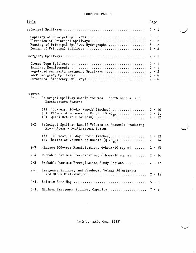
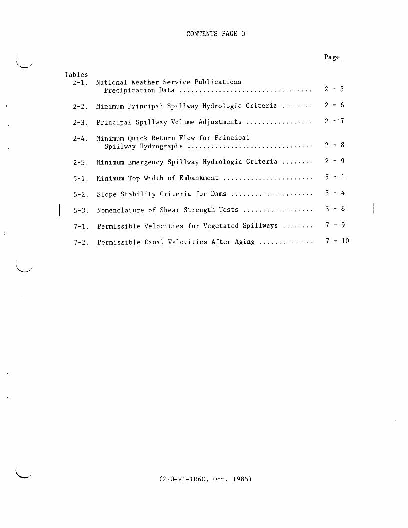
I
PREFACE
This Technical Release (TR) describes design procedures and provides minimum requirements for planning and designing earth dams and associated spillways This TR was developed to provide uniform criteria for earth dams and reservoirs SCS plans designs and constructs complex dams under widely varying conditions It is essential that these dams be constructed with uniform criteria to assure consistent performance As new experience materials and knowledge become available this document will be revised
This TR applies to all Class (a) dams with a product of storage times the effective height of the dam of 3000 or more those more than 35 feet in effective height and all Class (b) and (c) dams Requirements are stated as maximum or minimum limits and may not be satisfactory design criteria for all sites In some cases problems may arise where proven solutions are not ava~lable or alternative procedures may need to be evaluated before the best solutions can be developed and selected Experience state laws and regulations investigations analysis expected maintenance environmental considerations or safety laws may dictate more conservative criteria to insure satisfactory performance
This edition of the TR incorporates those revisions previously issued by changes on February 10 1982 June 2 1982 and April 6 1984 Also included are additions for peak breach discharge criteria streamflow diversion analysis conservation storage analysis updates on hydrometeorological report references and revision in embankment slope stability criteria
(210-VI-TR60 Oct 1985)
i
DEFINITIONS
Base flow is the sustained or fair-weather discharge which persists after storm runoff and associated quick return flow have been depleted It is usually derived from groundwater discharge or gradual snow or ice melt over extended periods of time but need not be continuous flow (It can be based on annual or seasonal periods depending upon when major floods usually occur)
Conservation storage is water impounded for consumptive uses such as municipal industrial and irrigation and non-consumptive uses such as recreation and fish and wildlife
The control section in an open channel spillway is that section where accelerated flow passes through critical depth
A dam is an artificial barrier together with any associated spillways and appurtenant works across a watercourse or natural drainage area which does or may impound or divert water
Design life is a period of time during which a dam is designed to perform its assigned functions satisfactorily~
A dry dam is a dam that has an ungated outlet positioned so that essenshytially all stored water will be drained from the reservoir by gravity The reservoir will normally be dry
An earth dam is a dam in which the principal barrier is an embankment of earth or rock fill or combination of earth and rock fill
An earth spillway is an open channel spillway in earth materials without vegetation
Economic life is the period of time during which economic benefits accrue to a dam
Effective height of dam is the difference in elevation in feet between the lowest open channel emergency spillway crest and the lowest point in the original cross section on the centerline of the dam If there is no open channel emergency spillway the top of the dam becomes the upper limit
The emergency spillway is the spillway designed to convey excess water through over or around a dam
The emergency spillway hydrograph is the hydrograph used to establish the dimensions of the emergency spillway
An emergency spillway system is a single emergency spillway or combination of emergency spillways designed to work togethr
(210-VI-TR60 Oct 1985)
ii
The exit channel of an open channel spillway is the portion downstream from the control section which conducts the flow to a point where it may be released without jeopardizing the dam
The freeboard hydrograph is the hydrograph used to establish the minimum settled elevation of the top of the dam It is also used to evaluate the structural integrity of the spillway system
The inlet channel of an open channel spillway is the portion upstream from the control section
Joint extensibility is the amount a pipe joint can be extended from the fully engaged position without losing strength or watertightness In case of rubbergasket joints it is measured from the center of the gasket to the point of flare of the bell ring or collar when the joint is fully closed
Joint gap is the longitudinal dimension between the end face of the spigot end of a pipe joint and the corresponding face of the bell end of the connecting pipe It does not include the beveled portion designed for sealing compounds
The joint use pool is the portion of a reservoir which serves two or more purposes for instance conservation storage and floodwater storage
A primary emergency spillway is the spillway with the lowest crest elevashytion in an emergency spillway system
The principal spillway is the lowest ungated spillway designed to convey water from the reservoir at predetermined release rates
The principal spillway hydrograph is the hydrograph used to determine the minimum crest elevation of the emergency spillway It is used to establish the principal spillway capacity and determine the associated minimum floodwater retarding storage
Quick return flow is the diminishing discharge directly associated with a specific storm that occurs after surface runoff has reached its maximum It includes base flow prompt subsurface discharge (commonly called interflow) and delayed surface runoff
A ramp spillway is a vegetated spillway constructed over an earth dam in a manner such that the spillway is a part of the embankment
The retarding pool is the portion of the reservoir allotted to the temshyporary impoundment of floodwater Its upper limit is the elevation of the crest of the emergency spillway
Retarding storage is the volume in the retarding pool
A rock spillway is an open channel spillway through competent non-erodible natural rock materials
(210-VI-TR60 Oct 1985)
iii
The sediment pool is the portion of the reservoir allotted to the accumulation of submerged sediment during the design life of the dam
The sediment pool elevation is the elevation of the surface of theI anticipated submerged sediment accumulation at the dam
Sediment storage is the reservoir capacity allocated to total sediment I (submerged and aerated) accumulation during the life of the dam
A spillway is an open or closed channel conduit or drop structure used to convey water from a reservoir It may contain gates either manually or automatically controlled to regulate the discharge of water
Storage is the capacity of the reservoir below the elevation of the crest of the emergency spillway
A vegetated spillway is a vegetated open channel spillway in earth materials
Visual Focal is an element in the landscape upon which the eyes automatically focus because the elements size form color or texture contrast clearly with its surroundings
middotmiddot~
(210-VI-TR60 Oct 1985)
1-1
General
Dam Classification
In determining dam classification a number of factors are to be considered Consideration is to be given to the damage that might occur to existing and future developments should the dam suddenly release large quantities of water downstream due to a breach failure r landslide into the reservoir The effect of failure on public confidence is an important factor State and local regulations and the responsibility of the involved public agencies are to be recognized The stability of the spillway materials the physical characteristics of the site and the valley downstream and the relationship of the site to industrial and residential areas including controls of future development all have a bearing on the amount of potential damage in the event of a failure
Dam classification is determined by the above conditions It is not determined by the criteria selected for design The policy on classification is in 210-V Part 520 Subpart C DAMS (National Engineering Manual)
Classes of Dams The following classes of dams have been established by policy and repeated here for convenience of the user
Class (a) --Dams located in rural or agricultural areas where failure may damage farm buildings agricultural land or township and country roads
Class (b) --Dams located in predominantly rural or agricultural areas where failure may damage isolated homes main highways or minor railroadE or cause interruption of use or service of relatively important public utilities
Class (c) --Dams located where failure may cause loss of life serious damage to homes industrial and commercial buildings important public utilities main highways or railroads
Peak Breach Discharge Criteria Breach routings are used to help delineate the area potentially impacted by inundation should a dam fail and can be used to aid dam classification
Stream routings made of the breach hydrograph are to be based upon topographic data and hydraulic methodologies mutually consistent in their accuracy and commensurate with the risk being evaluated
The minimum peak discharge of the breach hydrograph l regardless of the technique used to analyze the downstream inundation area is as follows
lf The breach hydrograph is the outflow hydrograph attributed to the sudden release of water in reservoir storage due to a dam breach
(210-VI-TR60 Revised Amend 1 Oct 1990)
1-2
1 For depth of water at the dam at the time of failure gt 103 feet
65 H 185Qmax V
2 For depth of water at the dam at the time of failure lt 103 feet
35Qmax 1100 Br 1middot bull
but is not to be less than
Qmax 32 12S
and need not exceed
Q 65 H 1 85 max middot-w
3 When the width of the valley L at the water surface elevation corresponding to the depth H is less than
65 u035 T
o416
replace the equation
in categories 1 and 2 above with the equation
Qmax 0416 L 11S Where
the peak breach discharge cfs
breach factor acre
Vs reservoir storage at the time of failure acre-feet
Rw depth of water at the dam at the time of failure however if the dam is overtopped depth is set equal to the height of dam feet
A cross-sectional area of embankment at the assumed location of breach usually the template section (normal to the dam longitudinal axis) at the general flood plain location sq ft
T theoretical breach width at the water surface elevation 1bull85corresponding to the depth H for the equation Qmax 65 tt
feet
L width of the valley at the water surface elevation corresponding to the depth llbull feet
(210-VI-TR60 Revised Amend 1 Oct 1990)
1-3
The peak discharge value determined by using principles of erosion hydraulics and sediment transport may be used in lieu of the peak discharge computed using the above equations
Utility Cables and Pipelines
Existing pipelines cables and conduits of a wide variety of sizes materials and functions are frequently encountered at dam sites These conduits are usually located at shallow depths in the flood plain They constitute a hazard to the safety of the dam and are to be (1) relocated away from the site or (2) reconstructed or modified to provide the durability strength and flexibility equal in all aspects to the principal spillway designed for the site in accordance with Service criteria and procedures Overhead cables or power lines are to be relocated or raised as necessary to prevent damage or hazard to the public
Every reasonable effort is to be made to have such conduits cables and pipelines removed from the site Most utilities and industries will want their facility removed from the site for easy maintenance Only as a last resort andunder the limitations imposed below are conduits to be permitted to remain under an earth dam embankment
Conduits permitted to remain under any part of the embankment below the crest of the emergency spillway are to be (1) provided with seepage control against I potential piping (2) properly articulated on all yielding foundations (3) encased in concrete or otherwise treated to insure durability and strength equal to that of the principal spillway and (4) made watertight against leaking either into or out of the pipe
Enclosure of the conduit cable or pipeline within another conduit which meets the requirements of this section and which is positively sealed at the upstream end to prevent seepage into the enclosing conduit is acceptable Such an enclosing conduit is to extend the full distance through which the conduit cable or pipeline being enclosed is beneath the embankment
Cut Slope Stability
Natural and excavation cut slopes are to be planned and formed in a stable and safe manner Spillways inlet and outlet channels borrow pits reservoir edges abutment areas and foundation excavations are all locations where these considerations are needed Field investigations methods of analysis design and construction requirements and resultant specifications are to recognize and provide for safe functional performance
Joint Use of Reservoir Capacity
A reservoir site may be used more efficiently where hydrologic conditions permit joint use of storage capacity by flood water and conservation storage The following requirements must be met for joint use storage dams
1 There is reasonable assurance that water will be available to meet objectives
(210-VI-TR60 Oct 1985)
1-4
2 Flood protection objectives of the project are satisfied
3 Spillway conditions are such that the dam will perform safely
Special hydrologic studies are to be made to show that the requirements can be met This may include hydrometeorologic instrumentation and analysis
Hydraulic features are to include an ungated spillway outlet at the top of the joint use pool A gated opening is to be provided at the bottom of the joint use pool adequate for use of the conservation storage and evacuation of J
the joint use pool
Provision are to be made for operation of the joint use pool to insure functioning of the dam as designed These are to include a competent operating and maintaining organization and a specific operation and maintenance plan These requirements are to be a part of the planning process and agreed to by the sponsors or owner
Visual Resource Design
The public generally prefers lake or waterscape scenery Therefore when permanent pools are created by dam construction they can enhance the visual resource if the water views are emphasized A visual design objective is to focus public views toward the permanent pool and reduce the visual focal effects of the structural elements
Visual focus on the lake is achieved by locating roads and walkways so that the entering or first perceptions of the site are of the waterscape scenery In most landscapes the lake will automatically predominate if other elements are visually designed to be subordinate
Borrow areas are to be shaped to blend with the surrounding topography These areas are to be revegetated with herbaceous and woody plants to visually fit the existing surrounding vegetation Fences are to be constructed parallel to the contour as much as possible be located behind existing vegetation as seen from the major view points and be placed low in the landscape Dams are to be shaped to blend with the natural topography to the extent feasible
Safety and Protection
Many dams are hazardous to the public Features designed for recreation or fish and wildlife are especially attractive to the public since they provide an opportunity to use the water All dams are to be designed to avoid hazardous conditions where possible Open-top risers steep-walled channels and chutes plunge pools and stilling basins are hazardous and require special attention All dams are to be provided with safety fences guard rails or other safeguards as necessary to protect the public and operation and maintenance personnel
The embankment and spillways are to be fenced where necessary to protect the dam from livestock and foot and vehicular traffic
(210-VI-TR60 Oct 1985)
1-5
Water Supply Pipes
Water supply pipes or conduits for other purposes installed under any part of the embankment below the crest of the emergency spillway are to (1) provide durability strength and flexibility equivalent to the principal spillway (2) be watertight against anticipated pressures (3) be adequate for their intended use and (4) be provided with seepage control against potential piping
Streamflow Diversion During Construction
Streamflow past the dam site unless controlled occurs at a somewhat random time with variable frequency of magnitudes A hazard exists during dam construction beginning when the embankment cofferdam or other ancillary structures obstruct the natural streamflow During construction a greater risk usually exists for some time period than after the dam is completed The risk is different for each dam because of the varying factors of construction time climate watershed size and diversion capacity An evaluation is to be made of the risk from embankment failure by overtopping and other similar hazards during construction The risk involved in overtopping during construction increases with the following factors
1 Dams of higher hazard class 2 Greater volume of reservoir storage 3 Dams with larger watersheds 4 Longer critical construction time periods 5 Smaller diversion release rates (less unit discharge per unit
watershed area)
The consequence of overtopping during construction may vary from a slight amount of erosion on a homogeneous clay dam to a breach of an embankment including loss of a temporary diversion coffer dam The erosion or breach causes increased inundation and sedimentation of downstream areas
The risk may be evaluated based upon experience of comparable dams constructed in the same hydrologic setting An evaluation may also be made using available streamflow records to obtain stage-duration-frequency information for a range of diversion rates Streamflow data should be used when available otherwise an evaluation may be made using climatalogical record data for generation of synthetic hydrographs to develop stageshyduration-frequency information for a range of diversion rates
The size of diversion is to be designed to provide an acceptable level of risk The probability required to protect against overtopping varies from 20 percent to 5 percent chance in any one year A 10 percent chance probability is frequently used when the critical construction period is limited to one construction season An alternative to a larger diversion capacity is to provide protection against erosion to the embankment surface (reinforcement) up to the desired elevation of acceptable risk
(210-VI-TR60 Qct 1985)
1-6
Reservoir Conservation Storage
Reservoirs with water stored for conservation purposes are to be analyzed using a water budget to determine a dependable water supply
For most purposes a dependable water supply is defined as one that is available at least 8 out of 10 years or has a probability of 80 percent chance in any one year A purpose such as municipal and industrial water may require a 95 percent chance probability of existing in any one year Other purposes such as recreation requires an analysis of the reservoir surface elevation fluctuation in order to evaluate the acceptable percent chance of occurrence
(210-Vl-TR60 Oct 1985)
2-1
HYDROLOGY
This section describes hydrologic criteria for determining spillway discharges and floodwater storage volumes Detailed procedures for developing principal spillway emergency spillway and freeboard hydrographs are contained in Chapter 21 Section 4 Hydrology of the SCS National Engineering Handbook (NEH-4) Methods of flood routing hydrographs through reservoirs and spillway systems are contained in Chapter 17 NEH-4 Special Studies as used in this text refer to all site specific studies with prior concurrence of selected procedures
Precipitation and Runoff Volumes
Principal Spillway Precipitation data are to be obtained from the most recent National Weather Service (NWS) reference which is applicable to the area under study Refershyences which contain precipitation data for return periods up to 100 years and for durations up to 10 days are listed in Sections A and B of Table 2-1
The return period for design precipitation amounts is dependent on the dam classification purpose size location and type of emergency spillway Minimum return periods are shown in Table 2-2 The minimum allowable areal adjustment ratios for 1 and 10-day precipitation amounts are tabulated in Table 2-3 part A
A storm duration of not less than 10 days is to be used for sizing the principal spillway The procedure in Chapter 21 NEH-4 for developing the storm distribution uses both the 1-day and 10-day runoff volumes
The procedure for estimating runoff volumes is to be selected based on which one requires the higher emergency spillway crest elevation when the principal spillway hydrograph is routed through the structure Procedures to be used to estimate runoff volumes include
(1) The runoff curve number (CN) procedure described in NEH-4 Use average antecedent moisture conditions (AMC II) or greater unless a special study shows that a different condition is justified The CN adjustment for a 10-day storm is estimated from Table 2-3 part B
(2) Runoff volumes from Figures 2-1 (A) and (B) or Figures 2-2 (A) and (B)
A special study may show that local streamflow records can be used directly or regionalized to develop design runoff volumes
Transmission losses reducing the runoff volume in arid and semiarid climatic areas may be used if the climatic index as defined in Chapter 21 NEH is less than one If transmission losses appear to be significant even though the climatic index is one or more such as in cavernous areas special studies are required
(210-VI-TR60 Oct 1985)
2-2
Obtain quick return flow from the map Figure 2-l(C) or Table 2-4 as appropriate
Emergency Spillway and Freeboard Table 2-5 establishes the minimum design precipitation amounts by dam class The most recent NWS references are to be used to estimate preshycipitation amounts in all areas The references are listed in Sections A and C of Table 2-1 The generalized maps Figures 2-3 and 2-4 can be used to establish the 10-square mile 100-year and the probable maximum precipitation (PMP) for the 37 contiguous states east of the 103rd meridian Figure 2-5 shows the location in which the NWS references for PMP are applicable
Areal adjustment and storm distribution factors contained in the NWS references listed on Figure 2-5 are to be used in their respective regions For areas not covered by an NWS publication minimum areal adjustment ratios for design precipitation amounts are shown on Graph A Figure 2-6 No areal adjustments are to be made for areas less than 10 square miles
The minimum storm duration to be used is 6-hours If the time of concentration (Tc) exceeds 6-hours the minimum design storm duration is to be equal to the Tc When the Tc exceeds 6-hours the precipitation amounts must be increased by the values in the applicable NWS references (Figure 2-S) The duration adjustment shown on Graph B Figure 2-6 may be used in areas where the NWS references are not applicable
For those locations where NWS references provide estimates of local storm (thunderstorm) and general storm PMP values the storm duration and distribution that result in the maximum reservoir stage when the hydrograph is routed through the structure should be used Unless a specific distribution is recommended in a NWS reference the distribution of precipitation with time should be approximately the same as that shown in Graph C Figure 2-6 For longer duration storms recommended distributions from NWS references should be used
The runoff curve number (CN) procedure in NEH-4 is used to determine runoff volumes using AMC II or greater The CN applies throughout the design storm regardless of the storm duration
The NWS may be requested to make special PMP studies for any location This includes but is not limited to drainage areas larger than 100 square miles areas of significant variation in elevation or areas located at the boundary of two studies where discontinuities in published values occur
(210-VI-TR60 Oct 1985)
2-3
Design Hydrographs
Principal Spillway Hydrographs Procedures in Chapters 16 and 21 NEH-4 and applicable national computer programs are to be used to develop the principal spillway hydrograph using precipitation and runoff amounts as described in the preceding section
When the area above a proposed dam is hydrologically complex the area should be divided into two or more hydrologically homogeneous subbasins for developing the design hydrograph
Streamflow records may be used to develop the principal spillway hydrograph where a special study shows they are adequate for this purpose
Emergency Spillway amp Freeboard Hydrographs Procedures in Chapters 16 and 21 NEH-4 and applicable national computer programs are to be used to develop emergency spillway and f reeboard hydrographs using precipitation and runoff amounts and subbasins if necessary as described in the preceding sections
Dams in Series
Upper Dam The hydrologic criteria and procedures for the design of an upper dam in a system of dams in series are to be the same as or more conservative than those for dams downstream if failure of the upper dam could contribute to failure of the lower dam The dam breach criteria contained on page 1-1 will be used to develop the breach hydrograph peak discharge
Lower Dam For the design of a lower dam hydrographs are to be developed for the areas controlled by the upper dams based on the same hydrologic criteria as the lower dam The hydrographs are routed through the spillways of the upstream dams and the outflows routed to the lower dam where they are combined with the hydrograph from the intermediate uncontrolled drainage area The combined principal spillway hydrograph is used to determine the capacity of the principal spillway and the floodwater retarding storage requirement for the lower site The combined emergency spillway hydrograph and the combined freeboard hydrograph are used to determine the size of the emergency spillway and the height of dam at the lower site
If upon routing a hydrograph through the upper dam the dam is overtopped or its safety is questionable it is to be considered breached For design of the lower dam the breach hydrograph is to be routed downstream to the lower dam and combined with the uncontrolled area hydrograph
In design of the lower dam the time of concentration (Tc) of the watershed above an upper dam is used to develop the hydrographs for the upper dam The Tc of the uncontrolled area above the lower site is used to develop the uncontrolled area hydrographs If the Tc for the total area exceeds 6-hours
(210-VI-TR60 Oct 1985)
2-4
the precipitation amounts for the emergency spillway and freeboard hydrographs must be increased by the values in the applicable NWS references (Figure 2-5)
The minimum precipitation amounts for each of the required hydrographs may be reduced by the areal reduction factor for the total drainage area of the dam system
Large Drainage Areas
When the area above a proposed dam approaches 50 square miles it is desirable to divide the area into hydrologically homogeneous subbasins for developing the design hydrographs Generally the drainage area for a subbasin should not exceed 20 square miles Watershed modeling computer programs such as the SCS Technical Release 20-Project Formulation-Hydrology or DAMS2-Structure Site Analysis may be used for inflow hydrograph development
If the Tc for the entire drainage area is greater than 6 hours storm durations longer than the Tc should be tested to determine the duration that gives the maximum reservoir stage for the routed emergency spillway and freeboard hydrographs
Precipitation amounts may exhibit marked variation in a large watershed This variation is based upon topographical and meteorological parameters such as aspect orientation mean elevation of subbasin and storm orientation Consideration is to be given to having the NWS make a special PMP study for large watersheds with drainage areas more than 100-square miles Individual watershed PMP studies can take into account orographic features that are smoothed in the generalized precipitation studies A special study also may be warranted in areas where significant snow melt can occur during the design storms
Studies to make use of available stream flow records are encouraged for purposes such as unit hydrograph development watetshed storage and timing effects and calibration of watershed models
(210-Vl-TR60 Oct 1985)
2-5
TABLE 2-1
NATIONAL WEATHER SERVICE REFERENCES - PRECIPITATION DATA
A Durations to 1 day and return periods to 100 years Technical Memorandum HYDR0-35 Durations 5 to 60 minutes for the
eastern and central states (1977) Technical Paper 40 48 contiguous states (1961)
(Use for 37 contiguous states east of the 105th meridian) Technical Paper 42 Puerto Rico and Virgin Islands (1961) Technical Paper 43 Hawaii (1962) Technical Paper 47 Alaska (1963) NOAA Atlas 2 Precipitation Atlas of the Western United States (1973)
Vol 1 Montana Vol II Wyoming Vol III Colorado Vol IV New Mexico Vol V Idaho Vol VI Utah Vol VII Nevada Vol VIII Arizona Vol IX Washington Vol X Oregon Vol XI California
B Durations from 2 to 10 da s and return eriods to 100 years Technical Paper 49 48 contiguous states (1964
(Use SCS West National Technical Center Technical Note shyHydrology - P0-6 Rev 1973 for states covered by NOAA Atlas 2)
Technical paper 51 Hawaii (1965) Technical paper 52 Asaska (1965) Technical paper 53 Puerto Rico and Virgin Islands (1965)
C Probable maximum precipitation (PMP) (See Figure 2-5) Hydrometeorological Report 36 California Pacific drainage (1961) Hydrometeorological Report 39 Hawaii (1963)
(PMP maps in TP-43 are based on HMR-39) Hydrometeorological Report 43 Northwest states Pacific drainage
(Rev 1981) Hydrometeorological Report 49 Colorado River and Great Basin
Drainages (1977) Hydrometeorological Report 51 For 37 contiguous states east of the
103rd meridian (1978) Hydrometeorological Report 52 Application of PMP estimates
states east of the 105th meridian (1982) Hydrometeorological Report 53 Seasonal variation of 10 square-mile
PMP estimates states east of the 105th meridian (1980) Hydrometeorological Report 54 PMP and snowmelt criteria for southeast
Alaska (1983) Hydrometeorological Report 55 Between the Continental Divide and the
103rd meridian (1984) Technical Paper 42gtdlt Puerto Rico and Virgin Islands (1961) Technical Paper 47 Jdlt Alaska (1963) New studies are in progress in the Tennessee River Watershed
National Weather Service National Oceanic and Atmospheric Administration (NOAA) US Department of Commerce formerly US Weather Bureau
degTechnical papers listed in both A and C
(210-VI-TR60 Oct 1985)
--
I
TABLE 2-2
MINIMUM PRINCIPAL SPILLWAY HYDROLOGIC CRITERIA N
Class Purpose of of
Dam Dam
~
N single --2
~
0 irrigation
lt1 I only
H I
l (a)
deg 0 single
0 or rt multiple shy() 41
(b) single or multiple
(c) single or multiple
Product of Storage x
Effective Height
less than 30000
greater than 30000
less than 30000
greater than 30000
all
all
all
Existing or Planned
Upstream Dams
none
none
any 2_
none or any
none or any
deg
Precipitation Data for Maximum Frequency 1 of Use of Emergency Spillway Types
Earth
12 design life
34 design life
Pso
12 (Pso + plOO)
PlOO
plOO
plOO
Vegetated
12 design life
34 design life
p25 11
12 (P2s + Psol
Pso
Pso
plOO
ll Precipitation amounts by return periods in years In some areas direct runoff amounts determined by figure 2-1 and 2-2 or procedures in Chapter 21 NEH-4 should be used in lieu of precipitation data
1_ Applies to irrigation dams on ephemeral streams in areas where the annual rainfall is less than 25 inches ]_ The minimum criteria are to be increased from P to P for a ramp spillway
25 100 ii Class (a) dams involving industrial or municipal water are to be designed with a minimum criteria equivshy
alent to that of class (b)
_ Applies when the upstream dam is located so that its failure could endanger the lower dam
l
2-7 TABLE 2-3
PRINCIPAL SPILLWAY VOLUME ADJUSTMENTS
A Minimum Areal Adjustment Ratios for Precipitation
Area AreaPoint Ratio for Area AreaPoint Ratio for Sq Mi 1 Day 10 Days Sq Mi 1 Day 10 Days
10 or less 1000 1000 45 0951 0976 15 0977 0991 50 0948 0974 20 0969 0987 60 0944 0972 25 0965 0983 70 0940 0970 30 0961 0981 80 0937 0969 35 0957 0979 90 0935 0967 40 0954 0977 100 0932 0966
B Ten-Day Runoff Curve Number Adjustment
Runoff Curve Numbers for
1 Day 10 Days 1 Day 10 Days 1 Day 10 Days 100 100 80 65 60 41
99 98 79 64 59 40 98 96 78 62 58 39 97 94 77 61 57 38 96 92 76 60 56 37 95 90 75 58 55 36 94 88 74 57 54 35 93 86 73 56 53 34 92 84 72 54 52 33 91 82 71 53 51 33 90 81 70 52 50 32 89 79 69 51 49 31 88 77 68 so 48 30 87 76 67 49 47 29 86 74 66 47 46 28 85 72 65 46 45 28 84 71 64 45 44 27 83 69 63 44 43 26 82 68 62 43 42 25 81 66 61 42 41 24
~This Table is used only if the 100-year frequency 10-day point rainfall is 6 or more inches If it is less the 10-day CN is the same as that for the 1-day CN
(210-VI-TR60 Oct 1985)
2-8
TABLE 2-4
MINIMUM QUICK RETURN FLOW FOR PRINCIPAL SPILLWAY HYDROGRAPHS
Ci QRF Ci
inday csm inday
100 00 00 150 0233 102 0011 030 152 0239 104 0022 060 154 0244 106 0033 090 156 0249 108 0045 120 158 0254
110 0056 150 160 0259 112 0067 180 165 0270 114 0078 210 1 70 0280 116 0089 240 l 75 0290 118 0100 270 180 0299
120 0112 300 185 0309 122 0122 329 1 90 0318 124 0133 358 195 0326 126 0144 386 200 0335 128 0153 412 205 0343
130 0163 437 210 - 0351 132 0171 461 220 0367 134 0180 483 230 0382 136 0188 505 240 0396 138 0195 525 250 o410
140 0202 544 260 0423 142 0209 563 270 o436 1 44 0216 580 280 0449 146 0222 597 290 0461 148 0228 613 3 00 -ki 0473
Change in tabulation interval For Ci greater than 3 use
5QRF(csm) =9 (Ci - 1) 0 middot QRF(inday) = QRF(csm) x 0037191
where QRF =quick return flow csm =cubic feet per second per square mile Ci = climatic index
QRF
csm
628 642 656 670 683
695 726 753 779 805
830 854 8 77 900 922
944 986
1026 1065 1102
1138 11 73 1207 1241 1273
(210-VI-TR60 Oct 1985)
( (
TABLE 2-5
MINIMUM EMERGENCY SPILLWAY HYDROLOGIC CRITERIA
Class Product Existing PreciPitation Data for Y of of or Planned Emergency
Dam Storage x Upstream Spillway Freeboard 0 Effective Height Dams Hydrograph Hydrograph lt
H
l less than 30000 none Piao plOO + 012 (PMP - plOO) 0
(a) Jj greater than 30000 none plOO + 006 (PMP - PlOO) plOO + 026 (PMP - plOO)
all any 1 plOO + 012 (PMP - plOO) plOO + 040 (PMP - PlOO)
none (b) all or plOO + Ol2 (PMP - PlOO) PlOO + 040 (PMP - plOO)
any
none0
ct (c) all or plOO + 0bull26 (PMP - PlOO) PMP any
3 _ = Precipitation for 100-year return period PMP = Probable maximum precipitationP100
3 Dams involving industrial or municipal water are to use minimum criteria equivalent to that of class (b) N I
1 Applies when the upstream dam is located so that its failure could endanger the lower dam
~
IgtI-
lt 0
d Hbull
deg0
~
iamp I-
0
rT
I-
~
degdeg0
(_
- bulloobull 9i 90deg osmiddot ~middot
Area I I i Area 2I
0
85
1
- middot 85 I tf~fo
_
middotI
Area 1 Area 2
40bull__
RATIOS FOR 50 AND 25-YEAR 10-DAY RUNOFF VOLUMES
To obtain Multiply map values byArea 1 Area 2 Area 3
50-YEAR 10-DAY RUNOFF 085 090 092 25-YEAA 10-DAY RUNOFF 070 080 085 Area 3
FIGURE 2middot1 (A) lOOmiddotYEAR 10-DAY RUNOFF (INCHES) PRINCIPAL SPILLWAY HYDROGRAPH
JANUARY 1971 REV APRIL 1976 OCTOBER 1990
l (_
( ( (
0
rt
LEGEND
0 1 - 1-Day Volume Runoff
010- 10-Day Volume Runoff
FIGURE 2-1 (B)
RATIOS OF VOLUMES OF RUNOFF (Q 11Q
10)
PRINCIPAL SPILLWAY HYDROGRAPH
JANUARY 1971 REV APRIL 1976
~
shybullOO ~middotmiddot cbull I I deg
IF~ R lt bull
middot~10
~
I Ngt-gt0I
Hlt I I -middot --~~---CUI V-lf-IJ-H
deg~
0
2
R i
rt I3 4
gt-gt
degln ~
Note For Wisconsin Michigan and eastern I
Iowa use csrn values in circles
FIGURE 2middot1 (C) QUICK RETURN FLOW (csm)
PRINCIPAL SPILLWAY HYDROGRAPH
JANUARY 1971 REV APRIL 1976
(_ ( (
( ( (
115deg r
---------~
~
N 0 I
ltl ----- --- H I
H ~ ashy0 I 40deg-_
0 ()
rt
00
~
-------middot-middot40
LEGEND
JltUgtj Pr1mar1ly snowmelt produced floods
CJ Primarily rain produced floods
[=J Deep snowpack areas
FIGURE 2-2 (A)50-YEAR 10-DAY RUNOFF-Use 85 of map value
25middotYEAR IO-DAY RUNOFF-Use 70 of map value 100-YEAR 10-DAY RUNOFF (INCHES)
PRINCIPAL SPILLWAY HYDROGRAPH SNOWMELT PRODUCING FLOOD AREAS ~
January 1971 Rev Apri I 1976 w
I
0(lrt
_ --1()LEGEND
[j Primarily snowmelt produced floods
LJ Primarily rain produced floods
C=J Deep snowpack areas
Q1 - I-Day Volume RunoffQ10 - 10-0ay Volume Runoff FIGURE 2-2 (B)
RATIOS OF VOLUMES OF RUNOFF (Q 1Q10)JANUARY 1971 REV APRIL 1976 PRINCIPAL SPILLWAY HYDROGRAPH SNOWMELT PRODUCING FLOOD AREAS
( ( (shy
t
bull middotf middotmiddot -~
~
N Use Maps in 0 I lt H I
NOAA Atlas 2 (1973-shyfor the middot
1 1
L v -1
ti[amp 6
lt
deg 0 D
0
rt
(Xgt gt
- ~
II I
0 I bull jTechntc~I- cpoundJ -11middot
ulwa~er 43 -uf)_r111962) 1 I -i~ ~ -f---
~ --middot-middot - 11
-shy
middot-~
bullmiddotmiddot
FIGURE 2-3 MINIMUM 100-YEAR PRECIPITATION
Technical Paper 42 6-HOUR 10-SOUARE MILES (inches) USWB (1961
Technical Paper 47 USWB ( 1963)
APRIL 1976 bullmiddot
middot1middot~
~-
~~-t--
-----shylt
~middotimiddot_ middot
c~ )I-middot_ 1)-~I
8 i
bull1f
EMERGENCY SPILLWAY AND FREEBOARD HYDROGRAPHS ---shy~-- - --shy
~~ ~ ~i~~ cbullbull1BOibull~ middot~
~ U1
-- __L I ___ -~-~- -- -~----middot--
SOURCE HYDROMETEOROGICAL REPORT 5 I CAllbullSbullason PMP - I 978)
middot
_1~ middotmiddot
middotmiddotmiddot~~~~middotmiddot-- _-_r---~lt-gt _ -~ ~~_4--7 l 1 + 1J )lt 4e -i--
Z2 f - -middotr gt dmiddotti~~ft_ ~ - shyI
- __ ~ Ji ~
N middotbull SEE FIClUR~ fL~ bull0I
IJlO~ftRE~q of= APPJicABLlIYlt1 bull bull Olt NWSREFltf~fNdES H - i --r -I fI f i _Mk f- iH +~i_middot~ t bull I0deg ~ I ri
rmiddotmiddot f n0 --J t
H bull I I
-J )I iI
cc Lrj
Vgt ~
I
~
Lmiddot-ief
II NOTE It basin areaI - is greaJer than I 0middot ~-4~I
squara_ miles aeeHydrctmet Reports 5 Iamp 52
-_ Stippled ares are regions
FIGURE 2-4 0 where detailed terrain K effects have not beenPROBABLE MAXIMUM PRECIPITATION ~ evaua ted8-HOUR 10-SQUARE MILES (lnchee) ~EMERGENCY SPILL WAY
AND FREEBOABDliYDROGRAPHS32 4-
Aug I 985
( ( c
( ( (
middot1cent pi - _ smiddot efer nmiddotcmiddote -_fbifmiddot __ _ middotz~K ALAKAmiddotmiddotmiddot~~ c-Tec~~i~ per 4middot1 USWB Cl~~middot _ -~~dlpmet gtoglcaReport 54 (I 9~~ middot
1 1
[ HAWAlti~tJNDSlOo~dfmbulli~or~loglcal Rep~rt 39 ( 1963 FIGURE 2-5
~t_PJJ~Rro=RICO -middot~T~ch~cal Rp~rt42 USWB CI t6 PROBABLE MAXIMUM PRECIPITATIONI) and -middotmiddot- -lt-~r -
ivlRGIN ISLANDS f(bull middot middot NWS REFERENCESJUDY REGIONS N I i t~
JI-bull~~i ~~ ~h~-S f middotgt-
I ~~ ~1~J Ii 1 Aug I 9lf5 ~ ~- -_~-middot--~-~- 1 ~-m~___z__~- 1b~--~
N
_I
10 I I 11 I I I 10 ltXgt
~09 1- - 1 TPACIFIC C0iSTA1 CL~AT+- ~ I - ~ t _HUMID 4ND SU 09
a-_z-
OB -------- ---- -f -1 - BHUM10 CLIM4Tf -
~
_ --+ I 4~ + -= I--
_ I D Atvo ~E 07 08
St1i114 -_1 _ - ---- _J__J-- ~-i-i- I--- --- li10 Cl -_0 +-shy~ 06 ~ 11fq f-
lI - ~+- t-r- Pgt
Ir----+-- -- ---- =gt 6 0
c c t+050 15 x20 25 30 35 40 45 50 60 70 BO 90 100DRAINAGE AREA IN SQUARE MILES
0
I~u 0
~ I
_ A) AREAL PRECIPITATION ADJUSTMENTS FOR gt-z gtshy
Z
00DRAINAGE AREAS 10 to 100 SQUARE MILES J ~a ~
H ~~I ~rl
lt~04~ zshylti i0 0i== 00
~~ 00c c
llt o
deg 0 I00 ~~
~ gt-gtshy zz0
0
~
0 2 3 4 5 6~~ TIME IN HOURSzzlti lti (C) SIX HOUR DESIGN STORM DISTRIBUTION0~
FIGURE 2-6 12 18 EMERGENCY SPILLWAY AND FREEBOARD
TIME IN HOURS VOLUME ADJUSTMENTS AND STORM DISTRIBUTION(B) RELATIVE INCREASE IN RAINFALL AMOUNT
FOR AREAS WHERE NWS REFERENCES DO NOTFOR STORM DURATIONS OVER SIX HOURS CONTAIN AN APPLICABLE PROCEDUREAug 1981
(_ ( (
3-1
SEDIMENTATION
Reservoirs used to store or retard water from surface runoff will trap and store a large portion of the sediment in the runoff water Thereshyfore allocate storage capacity for the calculated sediment accumulation during the design life of the reservoir Criteria and general procedures needed to determine the volume required for sediment accumulation and its allocation in the reservoir are contained in NEH-3 Sedimentation and TR 12 The latter also includes procedures for determining
1 The sediment yield for present conditions and for the future after planned land treatment and other measures are applied in the drainage area of the dam
2 The trap efficiency of the reservoir
3 The distribution and types of sediment expected to accumulate
4 The proportion of the sediment that will be continously submerged vs that aerated and
5 The densities to which the sediment will become compacted
__ If the amount of sediment accumulation calculated exceeds two watershed inches in 50 years for the uncontrolled drainage area of the darn reevaluate the entire watershed to determine if more economical methods of reducing sediment yield or trapping sediment may be feasible and applicable
(210-Vl-TR60 Oct 1985)
4-1
GEOLOGIC INVESTIGATIONS
The intensity and detail of geologic site investigations are to be consistent with the class of dam complexity of site geology and the data needed for
design General requirements procedures and criteria are set forth in 210-V Part 531 and NEH-8
Geologic conditions that require special consideration beyond the minimum investigations spelled out in the above reference are
1 Seismic Assessment -- Dams in zones 3 and 4 Alaska Puerto Rico and the Virgin Islands and high hazard [class(c)] dams in zone 2 (see figure 4-1) require special investigations to determine liquefaction potential of noncohesive strata including very thin layers and the presence at the site of any faults active in Holocene time As part of this investigation a map is to be prepa-red showing the location and intens i tr of magnitude of all intensity V or magnitude 4 or greater earthquakes of record and any historically active faults within a 100 kilometer radius of the site (Obtain earthquake information for this map in printout form from the Environmental Data Service attention D62 NOAA Boulder Colorado 80302 Telephone FTS 323-6472 Commercial (303) 499-1000 ext 6472) The report should also summarize other possible earthquake hazards such as ground compaction landslides excessive shaking of unconsolidated soils seiches and in coastal areas tsunamis
2 Subsidence -- Investigate the potential for surface subsidence due to past or future solid liquid (including ground water) or gaseous mineral extraction Consult the state geological andor evaluation National Engineering Manual 210-V Part 531 Subpart D sets forth criteria for these evaluations
Evaluate the impact of the preemption of mineral deposits including sand and gravel by dams and reservoirs
In arid and semiarid areas and in eolean deposits determine the potential of moisture deficient soil materials to collapse upon saturation or wetting If the potential exists make extensive and intensive site investigations to provide quantitative information for design and construction
3 Emergency Spillways -- Large dams with emergency spillways in soft rock or cemented soil materials that cannot be classified as soil as defined Jn TR 52 nor as rock as generally defined for engineering purposes and spillways in rocks with extraordinary defects require a special individu1l evaluation
(210-VI-TR60 Oct 1985)
4-2
4 Mass Movements -- Evaluate landslides and landslide potential at dam and reservoir sites especially those in shales and where unfavorable dipshyslope or other adverse rock attitudes occur Summarize the history of mass movement in the project area Emergency spillway cuts and reservoir effects must be given careful consideration
5 Karstic areas -- Limestone and gypsum in reservoirs and at damsites require special investigational methods and careful evaluation of subsidence leakage hazards and construction costs Multipurpose structures in these areas are especially critical
6 Multipurpose Dams -- Investigate the ground water regime and hydraulic characteristics of the entire reservoir area of water storage dams and evaluate for leakage Use the water budgets to determine the need for reservoir sealing
7 Other -- Special studies and evaluations may be necessary where such things as compaction shales some types of siliceous calcareous or pyritic shales rebound joints dispersed soils or artesian waters occur at a site
(210-VI-TR60 Oct 1985)
( (
0 I lt I
rel ll
0 0 () rt
00 U1 deg
Minimum Seismic Coefficients
Zone Coefficients-0shy
1 005 2 010
3amp4 Base on Seismic Assessment
0 Q
SEISMIC ZONE MAP of
CONTIGUOUS STATES f w
0
Q
l
Adapted From TM 5-809-10 NAVFAC P-355 AFM 88-3 Chapter 13 April 1973
f KAUAI
~ 8LIHUE
OAHU ocE~N NllHAU
~ HONOLULU
MOLOKAI I----
KAUN~
LANAI Cl~~ ~
N ~
0 P~c1f c bullLANAI I
lt1 H KAHOOLAWE I gt-l_ 10 0 10 20 30 40
deg STATUTE MILES 0 0 (l rt
bullHILO ~ MinimlDil Seismic Coeficients 00 Ln ~
gt-bull OQ
Zone Coefficients
ro 0 0
1 005 I
gt- 2 010
romiddot ro
3amp4 Base on Seismic Assessment
rt
SEISMIC ZONE MAP 0
Hawaii
Adapted From TM 5-809-10 NAVFAC 0-355 AFM 88-3 Chapter 13 April 1973
( ( (
5-1
EARTH EMBAlKMENTS AND FOUNDATIONS
Earth embankments constructed of soil and rock are the principal means of impounding water The earth embankment and its foundation are to withstand the anticipated loads without movements leading to failure Measures are to be provided for adequate seepage control
Height
The design height of an earth embankment is to be sufficient to prevent overshytopping during passage of either the (1) freeboard hydrograph or (2) the emergency spillway hydrograph plus the freeboard required for frost condishytions or wave action whichever is larger The design height must also meet the requirements for minimum emergency spillway depth The design height of the dam is to be increased by the amount needed to compensate for settlement
Top Width
The minimum top width of embankment is shown in Table 5-1
Table 5-1
Minimum Top Width of Embankment
Total Height of Embankment
(feet) (H) All
Dams
Top Width Single Purpose
Floodwater Retarding
(feet) Multipurpose
or other Purposes
14 or less 8 15 - 19 10 NA NA 20 - 24 12 25 - 34 14
H + 35 35 - 95 NA 14 5 Over 95 NA 16 26
The width may need to be greater than the above minimums to (1) meet state and local standards (2) accommodate embankment zoning (3) provide roadway access and traffic safety and (4) provide structural stability An increase in top width is a major design feature in preventing breaching after embankshyment slumping caused by earthquake ground motion
When the embankment top is used as a public roadway the minimum width is to be 16 feet for one-way and 26 feet for two-way traffic Guardrailsmiddot or other safety measures are to be used and are to meet the requirementsof the responsible road authority
(210-VI-TR60 Oct 1985)
5-2 Embankment Slope Stability
Analyze the stability of embankment slopes using generally accepted methods based on sound engineering principles Document all analyses or considerations in appropriate design reports and files Design the embankment cross section to provide adequate factors of safety against sliding sloughing or rotation in the embankment and foundation Use the appropriate degree of conservatism in the analysis that is consistent with the adequacy of the site investigation and soil testing program and with the complexity of the site and consequences of failure Minimum factors of safety are listed in table 5-2
Evaluate the effect of seismicity on each site Include the determination of whether the site is in a seismically active area its proximity to active faults and the predicted site ground motion intensity Use the minimum seismic coefficient shown in Figure 4-1 in the slope stability analysis when no special seismic assessment is made
Analyze embankment slope stability for the conditions and periods during the design life of the structure that are most critical or severe Use conditions in the analysis based on possible critical water levels and loadings of the embankment and foundation Consider and document the following conditions or periods (1) end of construction (2) steady seepage (3) rapid drawdown and (4) during seismic loading Use the shear strength parameters and minimum factors of safety indicated in Table 5-2 for each case The nomenclature for the various shear strength tests is listed in Table 5-3
Calculate the factor of safety based on the ratio of the shear strength available to the shear strength mobilized
Clearly document the conditions not analyzed correlated shear strength parameters or correlation to field performance
Consider the following additional details in conjunction with Table 5-2
I End of Construction Make a detailed analysis of this case when significant pore pressure development during construction is expected in either the embankment or foundation soils Embankment soils are to be tested at the highest likely placement water content and foundation soils are to be tested at saturation Select shear strength parameters according to Table 5-2
II Rapid Drawdown Analyze the stability of the upstream embankment slope for the condition created by a rapid drawdown of the water level in the reservoir Use a phreatic surface in the embankment developed from the emergency spillway crest with the water level in the reservoir drawn down to the crest of the lowest gated or ungated outlet Failure surfaces are to be confined to the embankment only if foundation soils are free-draining Use infinite slope stability equation appropriate to drainage conditions of the embankment soils whenever the c or c value being used in the analysis is zero In addition to the infinite slope analysis circular arch or sliding wedge analyses may be needed to check stability where failure surfaces could extend into weaker core
(210-VI-TR60 Oct 1985)
5-3
zones or into the foundation Select shear strength parameters according to Table 5-2
III Steady Seepage Without Seismic Forces Analyze the downstream slope for the condition of steady seepage developed from the water surface at the principal spillway crest In the analysis saturated soils will be subjected to uplift forces simulated by a piezometric surface developed from the emergency spillway crest Phreatic surfaces and piezometric surfaces may be developed using flow nets or Casagrande procedures Select shear strength parameters according to Table 5-2
IV Steady Seepage With Seismic Forces Analyze the downstream slope for the condition of steady seepage developed from the water surface at the principal spillway crest with a horizontal force equal to the effective weight multiplied by the earthquake coefficient applied at the failure surface (pseudo-static analysis) Uplift forces due to the reservoir at the emergency spillway level need not be included because of the very remote potential for the simultaneous occurrence of an earthquake and an emergency spillway storm event A two or three dimensional computer analysis may be used instead of a pseudo-static analysis if desired Select shear strength parameters according to Table 5-2
V Steady Seepage With and Without Seismic Forces Determine the results of the analysis using either the total stress or effective stress shear strength parameters that are the most limiting (those resulting in the lowest factor of safety) Analyses are to include the use of various combinations of total stress parameters in certain zones and effective stress parameters in other zones The combinations that may be most limiting can usually be narrowed to one or two by inspection and judgement without analyzing all possible combinations
VI Additional Guidance
A Effective stress shear strength parameters are generally the most limiting for any free draining soil
B Total stress shear strength parameters are generally most limiting for non-free draining foundation soils that exhibit positive pore pressure buildup during undrained shear testing
C Effective stress shear strength parameters are generally most limiting for non-free draining foundation soils that exhibit negative pore pressure buildup during undrained shear testing
D Analyses will generally have to be made using both total and effective stress shear parameters to determine the most limiting for non-free draining embankment soils that exhibit either small negative or positive pore pressures during undrained shear testing
E Effective stress shear strength parameters are generally most limiting for non-free draining embankment soils that exhibit highly negative pore pressures during undrained shear testing
F Total stress shear strength parameters are generally most limiting for non-free draining embankment soils that exhibit highly positive pore pressures during undrained shear testing
(210-VI-TR60 Oct 1985)
TABLE 5-2 SLOPE STABILITY CRITERIA FOR DAMS
Design Condition Primary Assumption Remarks Minimum Factor ___o_f__s a tot v
I bull End of construcshytion (upstream or downstream slope)
Significant construction pore pressures expected in cert a In zones of the embank~
ment or layers In the foundation
1
2
Embankment conshyta In 1ng Impershyvious sol Is at water contents aqua I to or greatagtr than optimum water content andor Saturated Impershyvious foundation strata too thick to tully consolishydate duriog construction
uu I 4 ( 13 ls acceptshyable for embankshyments on strong foundations Ie the fal lure surshyf ace Is I ocated entirely In the embankment)
Peryen1ous embankment zones andor foundashyt I on strata
CiT or CD
I I Rapid drawdown (upstream slope)
Drawdown sp 111 way
from the crest to
emergency the crest
Fa 11 ure surface can be confined to the
Use alternative I or 2 below -
1 2
of the ungated
lowest gated outlet
or embankment or extend Into the foundation 1 Lowest shear If low permeability sol ls are Involved
strength from composite enveshylope of CU and CiT
or
2 Most IJr_ltlng3 of CU or CU or a combination ot both
(For alternative 2 only use shear strength tat lure crterle ot 01+03 maximum for dilative soils tested with backpressure saturation techniques This Is to avoid rel lance on high coh~shyslon developed by negative pore presshysure as a result of water tension)- --~-------------------middotmiddot-middot--------------- ---------------middot------ ___________________________
NOTE See bottom of next sheet tor explanatfon of footnotes
(210-VI-TR60 Oct 1985)
(_
( ( (
TABLE 5-2 (Contd) SLOPE STABILITY CRITERIA FOR DAMS
Design Condition Primary Assumption Remarks Shear strength Minimum Factor To Be Used 12 of Safety-
I I I bull Steady seepage I bull Water surf ace at the Fal lure surface con- nr or CD 1 bull 5 without seismic principal spillway f In ed to the embank-forces (down- crest and phreatic ment on I y stream s 1ope) surface f u I I y developed
through the embankment
2 Plezometrlc surface for Fal lure surface Most I Jmitlng3 of cu 1 bull 5 estimating up I If t In extends Into the or m or a comb Ina-saturated so I I zones Is foundation tlon of both determined with water level at the emergency spillway crest
IV Steady seepage 1 bull Water surface at The Fal lure plane may be Most I imlting3 ot CU 1 bull 1 with seismic crest of the principal cont I ned to the or C1T or a comblnashyforces Cd own- spi 1 lway and phreatlc embankment or may tlon of both stream slope) surface f u I I y developed extend Into the
through the emban-kment foundation
1 Use CU or CD shear strength tor pervlous sol I zones within the foundation or embankment
2 Use Infinite slope stabl I lty analysis whenever the C or C Intercept strength Is zero tor so I Is that are -tested to simulate low cont In Ing pressures This situation exists for tal lure surfaces located near the embankment surface Minimum factor ot safety for the Infinite slope stability analysis Is 11
3 Most llmltlng Is the combination resulting In the lowest factor ot safety
n I
n
(210-VI-TR60 Oct 1985)
5-6
TABLE 5-3
NOMENCLATURE OF SHEAR STRENGTH TESTS
Test Parameters scs Common Condition Obtained Descriltion Abbreviation
Unconsolidated Total Y uu Q Undrained Stress
Consolidated Total Y cu R Undrained Stress
Consolidated Effective _I cu R Undrained with Stress pore pressures measured
Consolidated Effective Y CD ii s Drained Stress
ll Total stress shear strength parameters are determined when no drainage is allowed during the test using the external stresses imposed on the soil specimen When used in a total stress analysis the assumption made is that the pore pressure developed (negative or positive) during loading is the same in the laboratory as it is in the field
_I Effective stress parameters are determined from undrained tests by using the intergranular stresses (total stress minus the pore water stress) on the soil particles When used in an effective stress analysis any effects of pore pressure development (positive or negative) resulting from load application must be accounted for in the analysis
ii The CD tests allow drainage during load application If the load is applied slow enough complete drainage occurs so that no pore pressure develops and the shear strength parameters obtained should be the same as CU parameters
(210-VI TR60 Oct 1985)
5-7
Seepage
To the extent needed an analysis is to be made of anticipated seepage rates and pressures through the embankment foundation abutments and reservoir perimeter (when storage is desired) Controls and treatment should be adequate to (1) accomplish the intended reservoir function (2) provide a safely operating structure and (3) prevent damage to downstream property
Zoning
Embankment zoning can be used when needed to (1) obtain a stable structure with the most economical use of available materials (2) control seepage in a safe manner or (3) reduce to a minimum the uncertainties of material strengths and resultant stability
Embankment zones should be a minimum of 10 feet wide except for filters and drains with specified and controlled gradation Drains and filters should meet the requirements contained in Soil Mechanics Notes
Soil materials which exhibit significant shrinkage swell or dispersion are to be used only with extreme care If possible they should not be used for embankment construction When there is no economical alternative to their use they are to be (1) treated to improve their performance (2) placed in zones where effects will not be detrimental or (3) protected by use of filters and drains or self-healing transition zones
Surface Protection
Embankment surfaces are to be protected against surface erosion Protection may be vegetative gravel rock riprap soil cement structural or similar treatment of durable quality and proven satisfactory performance
Vegetative Protection Vegetative protection may be used on surfaces where the following conditions can be met (1) inundation of the surfaces is of such frequency that vegetative growth will not be inhibited (2) vigorous growth can be sustained under average climatic conditions by normal maintenance without irrigation and (3) stable protection can be designed according to the procedures in TR-56
Structural Protection Protection against wave erosion by riprap or other structural measures is to be provided as follows (1) for dams where vegetation will not provide effective control (2) for multiple purpose dams and (3) for dams with fluctuating normal water levels
Protection is to extend from the lowest drawdown elevation that presents an erosion hazard to a few feet above the crest of the lowest ungated spillway The upper limit is to be based on an analysis of anticipated wave height and run up
Quality of riprap and other structural protection is to be consistent with the anticipated life of the dam and designed to be structurally stable
(210-VI TR60 Oct 1985)
6-1
PRINCIPAL SPILLWAYS
The structural design and detailing of principal spillways are to conform to the recommendations of National Engineering Handbook Section 6 Structural Design and SCS standard drawings All component parts of principal spillways except easily replaceable parts such as gates and trash racks are to be equally durable
Capacity of Principal Spillway
The required capacity of the principal spillway depends on (1) purpose of the dam (2) the amount of storage provided by the retarding pool (3) the kind of emergency spillway (4) stream channel capacity and stability downstream (5) potential damage from prolonged storage in the retarding pool (6) potential damage downstream from prolonged high outflow rates (7) possibility of substantial runoff from two or more storms in the time required to empty the retarding pool (8) limitations imposed by water rights or other legal requirements (9) environmental concerns (10) planned or potential alterations of the channel downstream and (11) the necessity to pass base and flood flows during construction
The principal spillway may be single-stage having an ungated inlet at only one elevation or multiple-stage having inlets at two or more elevations In the case of multiple-stage spillways the lower stage or stages usually perform the primary flood control function and the high stage has the capacity needed to prevent the emergency spillway from functioning more frequently than permissible
The principal spillway capacity should be adequate to empty the retarding pool in 10 days or less This requirement is considered to be met if 15 percent or less of the maximum volume of retarding storage remains after 10 days Where low release rates are required to meet the objectives of the project a longer period than 10 days may be needed For these situations additional storage is required to minimize the opportunity for increased frequency of emergency spillway flow due to recurring storms
Compute the 10-day drawdown from the time the maximum water surface elevation is attained during the passage of the principal spillway hydrograph The entire design inflow hydrograph including quick return flow upstream releases and outflow are to be considered in determining the evacuation time of the retarding storage The inflow from storm runoff must be considered for the entire evacuation time
For dams where more than 15 percent of the retarding storage volume remains after 10 days the elevation of the crest of the emergency spillway will be raised The raised crest elevation is determined by adding the remaining retarding storage volume to the initial retarding storage volume
(210-Vl-TR60 Oct 1985)
6-2
Elevation of Principal Spillways
Single Purpose Floodwater Retarding Dams The crest of the principal spillway or of the low stage inlet of a two-stage principal spillway is to be set at the sediment pool elevation For dry dams the elevation of the principal spillway inlet is to be placed as described above and provisions are to be made to drain the reservoir in a reasonable time and thus satisfy the functional or legal requirements of the dam
Other Dams When conservation storage is to be provided the elevation of the crest of the lowest ungated inlet of the principal spillway is to be determined by the volume area or depth of water required for the planned purpose or purposes and the required sediment storage The lowest crest may be the crest of the low-stage inlet single-stage inlet or an open spillway
Routing of Principal Spillway Hydrographs
Reservoir flood routing used to proportion dams and associated spillways is to be based on the assumption that all sedimentation expected in the reservoir during its design life has occurred The reservoir stage-storage curve used for routing should reflect the anticipated accumulation of sediment The initial reservoir stage for principal spillway hydrograph routing is to be at the crest of the lowest ungated inlet or (if not subtracted from the stage-storage curve) the anticipated elevation of the sediment storage whichever is higher except as provided in items 1 2 and 3
1 For dams with significant base flow principal spillway hydrograph routings must start not lower than the elevation of the water surface associated with the base flow Significant base flow is average annual or seasonal flow that would produce at least 05 feet of head over the lowest principal spillway inlet immediately prior to a flood or occupy more than 10 percent of the floodwater storage capacity
2 For dams with joint use storage capacity when one of the uses is floodwater detention routing of the principal spillway hydrograph may begin at the lowest anticipated elevation of the joint use pool in accordance with the operation plan
3 Single purpose class (a) irrigation dams with gated outlets and earth or vegetated emergency spillways which are located on ephemeral streams in areas where the average annual precipitation is less than 25 inches may be considered to have discharged up to 70 percent of the storage exculsive of sediment storage in determining the elevation to start routing
Design of Principal Spillways
Hydraulics The principal spillway is to be designed to carry the planned flow for expected head and tailwater conditions TR-29 Design Note No 8 NEH-5 the Engneering Field Manual for Conservation Practices and other appropriate references are to be used for hydraulic design
(210-VI-TR60 Oct 1985)
6-3
Risers Risers for drop inlet spillways are to be designed to maintain the reservoir pool level at or near the inlet crest elevation during low flow periods to establish full pipe flow at as low a head over the crest as practical and to operate without excessive surging noise vibration or vortex action at any reservoir stage Ibis requires the riser to have a larger cross sectional area than the conduit Standard risers have an inside width equal to the width (diameter) D of the conduit and an inside length equal to three times the width (diameter) of the conduit (D x 3D cross section)
Risers are to be designed to exclude trash too large to pass freely through the spillways including the outlet structure and to facili shytate the passage of smaller trash Standard D x 3D risers tend to line up longer pieces of trash and facilitate their passage into and through the conduit Covered risers with standard skirted or baffle inlets should be used in most cases because they are most effective in excluding trash without becoming clogged Skirted inlets having a cover with skirts extending below the weir crest elevation are applicable where backfill or settlement levels are to be at least two times the conduit width (diameter) below the crest Baffle inlets are applicable for risers that are to be backfilled to the crest eleshyvation or where sediment is expected to build up to the crest elevation
Risers are to be designed structurally to withstand all water earth ice and earthquake loads to which they may be subjected Articulation is to be provided to allow movement of the riser with respect to the conduit
Risers with low-stage inlets at or near the bottom are to be provided with concrete aprons to prevent erosion of soil and undermining of the riser footing by high velocity flow approaching the inlet
Standard risers are to be used where applicable for class (a) dams with an effective height of more than 35 feet and for all class (b) and class (c) dams Prefabricated pipe risers are permissible where hydraulically and structurally adequate for class (a) dams not more than 35 feet in effective height The riser pipe is to be of the same material as the conduit and at least one standard pipe size larger then the conduit pipe
Special riser designs are required for spillways having maximum conduit velocities more then 30 feet per second and for spillways having conduits larger then 48 inches in width (diameter) Generally these should be similar to standard risers but a special elbow and transition is required at the junction of the riser and conduit and special design of the inlet may be necessary Hydraulic model testing should be considered if the maximum total head on the spillway is more than 75 feet or the conduit velocity exceeds 50 feet per second
(210-Vl-TR60 Oct 1985)
6-4
Conduit The conduit should be straight in alignment when viewed in plan Changes from straight alignment if required are to be accomplished by watertight angle changes at joints or by special elbows having a radius equal to or greater than the diameter or width of the conduit Thrust blocks of adequate strength are to be provided if special pipe elbows are used They are to be designed to distribute the thrust due to change in direcshytion for the maximum possible discharge Drop inlet conduits are to be installed with enough slope to insure free drainage to the outlet of all parts of the conduit (including camber) at the time of construction and under the maximum anticipated settlement
All condbull1its under earth embankments are to support the external loads with an adequate factor of safety They are to withstand the internal hydraulic pressures without leakage under full external load and settlement They are to convey water at the design velocity without damage to the interior surface of the conduit
Principal spillway conduits under earth dams may be designed to support fill heights greater than the original constructed height if there is a reasonable possibility that the embankment height may be raised later to incorporate additional storage for some approved beneficial use
Rigid principal spillway conduits are to be designed as positive projecting conduits in accordance with the principles and procedures given in TR-5
Principal spillway conduits are to be of reinforced concrete pressure pipe or cast-in-place reinforced concrete unless corrugated steel or welded steel pipe is used in accordance with subsection 2 which follows
Cast-in-place rectangular reinforced concrete conduits are to be designed in accordance with principles and procedures in TR-42 TR-45 or other appropriate design aids
For Reinforced Concrete Water Pipe - - Steel Cylinder Type Prestressed ~eting specification AWWA C301 the 3-edge bearing strength at the first 0001-inch crack is to be used with a safety factor of at least one
For Reinforced Concrete Water Pipe - - Steel Cylinder Type Not Prestressed meeting specification AWWA C300 for Reinforced Concrete Water Pipe -Noncylinder Type Not Prestressed meeting specification AWWA C302 and for other types of reinforced concrete pipe the 3-edge bearing strength at the first 001-inch crack is to be used with a safety factor of at least 133
Elliptical or other systems of reinforcement requiring special orientation of pipe sections are not permitted in spillway conduits
Reinforced concrete pipe is to be designed to support at least 12 feet of earth fill above the pipe at all points along the conduit
(210-VI-TR60 Oct 1985)
6-5
1 Reinforced Concrete Pipe - (A) Minimum Inside Diameters on Yielding Foundations Class (a) dams The minimum diameter of the principal spillway conduit is to be 30 inches unless a joint extension safety margin of at least 15 inches is used in which case the minimum diashymeter is to be 18 inches for maximum fill heights up to 50 feet at the centerline of the dam and 24 inches for greater fill heights
Class (b) dams The minimum diameter of the principal spillway conduit is to be 30 inches unless a joint extension safety margin of 15 inches is used in which case the minimum diameter is to be 24 inches
Class c) dams The minimum diameter of the principal spillway conduit is to be 30 inches
(B) Minimum Inside Diameters on Non-Yielding Foundations The minimum diameter of the principal spillway conduit for class (a) dams is to be 18 inches for heights up to 50 feet at the centerline of the dam and 24 inches for heights greater than 50 feet and 24 inches for all class (b) and (c) dams The conduit and cradle or bedding are to rest directly on firm bedrock thick enough so that there is essenti shyally no foundation consolidation under the conduit Under these conditions the cradle or bedding under the conduit need not be articulated
2 Corrugated Steel Pipe or Welded Steel Pipe - Principal spillways of corrugated steel or welded steel pipe may be used for single purpose class (a) dams with the product of storage times effective height of dam less than 10000 While installation costs of steel pipes may be less concrete may compare favorably with steel when replacement costs and associated problems are considered
In each case the following limitations apply
a Diameter of pipe not less than 18 inches b Height of fill over the pipe not more than 25 feet c Provision for replacement if the materials will not
last for the design life of the structure d Pipe structurally strong enough to withstand outside
loads and hydraulic pressure e Pipe Watertight
Corrugated steel pipe is to be close riveted asbestos treated and asphalt coated with watertight connecting bands The minimum gage is to be that designed for 35 feet of fill over the pipe
Welded steel pipe conduits are to be structurally designed as rigid pipe A joint extension safety margin of 15 inches is to be provided for conduits on yielding foundation Welded steel pipe is to be protected by a Class A exterior coating as defined in the specifications guide for steel irrigation pipeline Engineering Practice Standard 432-F (NEH-2) or by an exterior coating of coal tar-epoxy paint conforming to Paint System I Construction Specification 82 (NEH 20)
(210-VI-TR60 Oct 1985)
Joints between lengths of corrugated steel or welded steel pipe other than welded joints are to be electrically bridged on the outside of the pipe with insulated copper wire 6 AWG or larger securely attached to the uncoated pipe metal at both sides of the joint This requirement applies whether or not the cathodic protection is completed by the installation of anodes etc The wire s hould have a tough waterproof insulation designed for direct burial with a rating of at least 600 volts Bare wire and exposed pipe metal at the points of connection are to be thoroughly coated with a coating equivalent to the original pipe coating to prevent the entry of moisture
Soil investigations for resistivity and pH of the subgrade and backfill materials to be adjacent to the condui t are to be made The resis t ivity measurements are to be made on saturat ed samples
Cathodic protection is to be provided for welded steel pipe conduits according to the criteria in Engineering Practice Standard 432-F (NEH-2) and 432-F specifications guide
Cathodic protection meet i ng the above r equirements i s to be provided for corrugated steel pipe in soil whose resistivity in a saturated condition is less than 4000 ohms-cm or whose pH is lower than 5 0
If cathodic protection is not required according to the above criteria and anodes are not installed during construction of the dam pipe- to-soil potentials are to be measured within the first 2 years after construction or after the water level has stabilized and when t he soil around the conduit is estimated to be at its normal post-construction moisture content Cathodic protection is to be installed at this time if such measurements indicate it is needed
Joints Conduit joints are to be des i gned and constructed to remain watertight under maximtun anticipated hydrostatic head and maximum probab l e joint opening as computed from Standard Drawing ES- 146 and r e l ated procedures of TR 18 including the effects of joint rotation and the required margin of safety The required joint extensibility is equal to the unit horizontal strain in the earth adjacent to the conduit multipl i ed by the length (in inches) of the section of conduit between joints plus the extension (in inches) due to calculated joint rotation plus a margin of safety
A margin of safety of not less than 05 inch shall be used The required joint extensibility plus the maximum permissible joint gap equals the required joint length The required joint extensibility depends on the maximum
potential foundation consol i dation under the spillway barrel For class (b) and (c) dams the consolidation is to be estimated f r om adequate founshydation borings and samples soil mechanics l aboratory tes ts and engineering analysis For class (a) dams where undis turbed foundation samples are not taken for other purposes approximate procedures based on soil classification and experience may be used for estimating foundation consolidation
(210-VI-TR60 Oct 1985)
6-7
Only joints incorporating a round rubber gasket set in a positive groovewhich will prevent its displacement from either internal or external pressure under the required joint extensibility are to be used on precast concrete pipe conduits Concrete pipe must have steel joint rings providing rubber to steel contact in the joint
Articulation of the conduit (freedom for required rotation) is to be provided at each joint in the conduit at the junction of the conduit with the riser and any outlet structure Concrete bedding for pipe conduits need not be articulated Cradles are to be articulated if on yielding foundations Welded steel pipe conduits need not be articulated if the pipe and bedding rest directly on firm bedrock
Piping and Seepage Control - Use a filter and drainage diaphragm around any structure that extends through the embankment to the downstream slopeDesign the diaphragm with single or multizones to meet the requirements of Soil Mechanics Note No 1
Locate the diaphragm aligned approximately parallel to the centerline of the dam or approximately perpendicular to the direction of seepage flow Extend the diaphragm horizontally and vertically into the adjacentembankment and foundation to intercept potential cracks poorly compactedsoil zones or other discontinuities associated with the structure or its installation
Design the diaphragms to extend the following minimum distances from the surface of rigid conduits
l Horizontally and vertically upward 3 times the outside diameter of circular conduits or the vertical dimension of rectangular box conduits except that
a the vertical extension need be no higher than the maximum potential reservoir water level and
b the horizontal extension need be no further than 5 feet beyond the sides and slopes of any excavation made to install the conduit
2 Vertically downward
a for conduit settlement ratios (o) of 07 and greater (reference SGS Technical Release No 5) the greater of (l) 2 feet or (2) 1 foot beyond the bottom of the trench excavation made to install the conduit Terminate the diaphragm at the surface of bedrock when it occurs within this distance Additional control of general seepage through an upper zone of weathered bedrock may be needed
b 15 times the outside diameter of circular conduits or the outside vertical dimension of box conduits for conduit settlement ratios (o) less than 07
(210-VI-TR60 Revised Amend 1 Oct 1990)
6-8
Design the diaphragms to extend in all directions a minimum of 2 times the outside diameter from the surface of flexible conduits except that the diaphragm need not extend beyond the limits in la and lb above nor beyond a bedrock surface beneath the conduit
Provide minimum diaphragm thickness of 3 feet and minimum thickness of 1 foot for any zone of a multizone system Use larger thickness when needed for (1) capacity (2) tieing into embankment or foundation drainage systems (3) accommodating construction methods or (4) other reasons
For homogeneous dams locate the diaphragm in the downstream section of the dam such that it is
1 Downstream of the cutoff trench
2 Downstream of the centerline of the dam when no cutoff trench is used and
3 Upstream of a point where the embankment cover (upstream face of the diaphragm to the downstream face of the dam) is at least one-half of the difference in elevation between the top of the diaphragm and the maximum potential reservoir water level
For zoned embankments locate the diaphragm downstream of the core zone andor cutoff trench maintaining the minimum cover as indicated for homogeneous dams When the downstream shell is more pervious than the diaphragm material locate the diaphragm at the downstream face of the core zone
~ Lt is good practiceto tie these diaphragms into the other drainage systems in the embankment or foundation Foundation trench drains andor embankment chimney drains that meet the minimum size and ~ocation limits are sufficient and no separate diaphragm is needed
Design the minimum capacity of outlets for diaphragms not connected to other drains by assuming the coefficient of permeability (k) in the zone upstream of the diaphragm is 100 times the coefficient of permeability in the compacted embankment material Assume this zone has a cross-sectional area equal to the diaphragm area and the seepage path distance equal to that from the embankment upstream toe to the diaphragm This higher permeability simulates a sealed filtet face at the diaphragm with partially filled cracks and openings in the upstream zone
For channels chutes or other open structures seepage and piping control can be accomplished in conjunction with drainage for reduction of uplift and water loads The drain properly designed to filter the base soils is to intercept areas of potential cracking caused by shrinkage differential settlement or heave and frost action These structures
9 US Government Printing Office 1991 - 282-95740388
(210-VI-TR60 Revised Amend 1 Oct 1990)
- ~ -
6-9
usually require the use of footings keywalls and counterforts and drainage is properly located iDBDediately downstream of these features This drainage when properly designed can control pip1ng and provide significant economies due to the effect on soil loads uplift pressures overturning forces and sliding stability
Outlets
The choice of outlet is to be based on a careful consideration of all site and flow conditions that may affect operation and energy dissipation
1 Cantilever outlet and plunge pools may be installed where their use
a Does not create a piping hazard in the foundation of the structure
b Is compatible with other conditions at the site
Plunge pools are to be designed to dissipate the energy and be stable Unless the pool is to be in bedrock or very erosion resistant materials riprap will be necessary to insure stability Design Note 6 entitled Armored Scour Hole for Cantilever Outlet is to be used for design
Cantilever outlets are to be supported on bents or piers and are to extend a minimum of 8 feet beyond the bents or piers The bents are to be located downstream from the intersection of the downstream slope of the earth embankment with the grade line of the channel below the dam They are to extend below the lowest elevation anticipated in the plunge pool The invert of the cantilever outlet is to be at least 1 foot about the tailwater elevation at maximum discharge
2 SAF basins may be used when there is adequate control of tailwater Use TR-54 for structural design and NEH-14 for hydraulic design
3 Impact basins may be used when positive measures are taken to prevent large debris from entering the conduit TR-49 is to be used for hydraulic design
Trash Racks
Trash racks are to be designed to provide positive protection against clogging of the spillway under any operating level The average velocity of flow through a clean trash rack is not to exceed 25 feet per second under the full range of stage and discharge Velocity is to be computed on the basis of the net area of opening through the rack
If a reservoir outlet with a trash rack or a ported concrete riser is used to keep the sediment pool drained the trash rack or riser is to extend above the anticipated sediment elevation at the riser to provide
(210-VI-TR60 Oct 1985)
for full design flow through the outlet during the design life of the dam The velocity through the net area of the trash rack above the maximum sediment elevation must not exceed 2 feet per second when the water surface in the reservoir is 5 feet above the top of the trash rack or riser inlet
Antivortex Device
All closed conduit spillways designed for pressure flow are to have adequate antivortex devices
High Sulfate Areas
Under certain conditions concrete is susceptible to deterioration from sulfate ions especially those derived from sodium and magnesium sulfates In areas where experience or soil tests indicate the potential for problems the following table will be used for design purposes
Sulfate Concentration (parts per million) Hazard Corrective Measures
0 - 150 Low None
150 - 1000 Moderate Use Type II Cement (ASTM C-150) Adjust mix to protect against sulfate action
1000 - 2000 High Use Type V Cement (ASTM C-150) Adjust mix to protect against sulfate action Use soils in contact with concrete surfaces that are low in sulfates
2000 - up Do not use concrete materials unless measures are taken to protect concrete surfaces from sulfates Product manufacturers should be consulted
Sulfate concentration is for soil water at the concrete surface
7-1
EMERGENCY SPILLWAYS _
Emergency spillways are provided to convey excess water through over or around a dam They are usually open channels excavated in natural earth earthfill rock or constructed of reinforced concrete
Closed Type Spillways
An open channel emergency spillway is to be provided for each dam except as provided below
1 Class (a) dams with a product of storage times the effective height of the dam of less than 10000 - A closed conduit principal spillway havshying a conduit with a cross-sectional area of 12 square feet or more an inlet which will not clog an elbow designed to facilitate the passage of trash and large enough to pass the routed freeboard hydrograph is the minimum acceptable design without an open channel emergency spill shyway The minimum capacity will be taken from Figure 7-1
2 Dams with drainage areas of 10 square miles or less (except those covered by item 1) - A closed conduit principal spillway having a conduit with a cross-sectional area of 20 square feet or more an inlet which will not clog an elbow designed to facilitate the passage of trash and large enough to pass the routed f reeboard hydrograph peak discharge without overtopping the dam is the minimum acceptable design without an open channel emergency spillway In no case is the capacity of the spillway provided to be less than that determined from Figure 7-1
3 Dams with drainage areas greater than 10 square miles (except those covered by item 1) - A closed type primary emergency spillway may be used in lieu of an open channel emergency spillway Drop inlet spill shyways with a standard two-way covered top inlet are to have a minimum unobstructed cross-sectional area of each opening of the conduit of 40 square feet All other closed type primary emergency spillways are to have a minimum unobstructed cross-sectional area of each opening of 80 square feet The ratio of width to height in both cases is to be between 075 and 133 The spillways must be large enough to pass the routed freeboard hydrograph peak discharge without overtopping the dam In no case is the capacity of the primary emergency spillway provided to be less than that determined from Figure 7-1
Spillway Requirements
Capacity of Emergency Spillways Emergency spillways are to be proportioned so they will pass the emergency spillway hydrograph at the safe velocity determined for the site They are to have sufficient capacity to pass the freeboard hydrograph with the water surface in the reservoir at or below the elevation of the design top of the dam In no case is the capacity of the emergency spillway to be less than that determined from Figure 7-1 The minimum difference in
(210-Vl-TR60 Oct 1985)
7-2
elevation between the crest of the emergency spillway and the settled top of the dam is three feet
State law may establish minimum capacity or depth greater than those given above
Elevation of the Crest of the Emergency Spillway Table 2-2 Page 2-6 gives the maximum allowable frequency of use of earth and vegetated emergency spillways The minimum retarding storage volume and the associated principal spillway discharge are to be such that (1) the discharge through the emergency spillway will not occur during the routing of the principal spillway hydrograph and (2) the 10-day drawdown requirement is met or the crest elevation of the emergency spillway is raised as noted on page 6-1 Capacity of Principal Spillway
For earth spillways it refers to sites where peak flows of short duration may be expected and where erosion resistant soils and moderate slopes exist When vegetated spillways are used the sites must have these same characteristics and in addition conditions must be such that vigorous vegetation can be maintained without irrigation When conditions are less favorable emergency spillways are to be designed for less frequent use This may be done by (1) raising the crest elevation (2) increasing the capacity of the principal spillway (3) adding a structural primary emergency spillway or (4) a combination of the above
The maintenance required for the emergency spillway will be increased as the frequency and duration of flow increase Good design requires balancing the spillway maintenance cost against the increased cost of modifying the other elements of the dam to reduce the flow frequency
Emergency Spillway Routings The emergency spillway and the f reeboard hydrographs are to be routed through the reservoir starting with the water surface at the elevation of the lowest ungated principal spillway inlet the anticipated elevation of the sediment storage the elevation of the water surface associated with significant base flow or the pool elevation after 10 days of drawdown from the maximum stage attained when routing the principal spillway hydrograph whichever is higher except as provided in items 1 and 2
1 Dams with gated spillways and joint use storage capacity - Emergency spillway and freeboard hydrograph routings are to be started at or above the elevation of the lowest ungated outlet or at the elevation of the water surface associated with the average annual base flow whichever is higher
2 Single purpose class (a) irrigation dams - Emergency spillway and freeboard hydrograph routings are to be started at or above the water surface elevation of the irrigation storage
(210-VI-TR60 Oct 1985)
7-3
Hydraulic Design The relationship between the water surface elevation in the reservoir and the discharge through the emergency spillway is to be evaluated by computing the head losses in the inlet channel upstream of the control section or if a control section is not used by computing the water surface profile through the full length of the spillway Bernoullis equation and Mannings formula are to be used to evaluate friction losses compute water surface profiles and determine velocities Policy on the selection of n11 values is given in the discussion of the various types of emergency spillways
Structural Stability The spillway is to be investigated analyzed designed and constructed adequately to establish and maintain stability during the passage of design flows without blockage or breaching Excavated open cut spillways arr to have cut and fill slopes in earth and rock which are stable against slmiddotding Cut slope stability is to be evaluated for the long term weathered natural moisture condition and for adverse moisture conditions associated with rapid drawdown from the emergency spillway design discharge
Vegetated and Earth Emergency Spillways
Vegetated and earth emergency spillways are open channels and usually consist of an inlet channel a control section and an exit channel Subcritical flow exists in the inlet channel and the flow is usually supercritical in the exit channel
Vegetated emergency spillways are usually trapezoidal in cross-section and are protected from damaging erosion by a grass cover They are adapted to sites where a vigorous grass growth can be sustained by normal maintenance without irrigation
Earth spillways are used in those areas where vegetative growth cannot be maintained They are similar to vegetated spillways but are designed for lower permissible velocities and less frequent use Normally they will require more maintenance after a flow occurs
Earth and vegetated emergency spillways are designed on the basis that some erosion or scour may be permissible if its occurrence is infrequent if maintenance facilities are provided and the spillway will not breach during passage of the freeboard storm
TR 2 outlines layout procedures and TR 39 contains hydraulic data to be used in the design of vegetated or earth emergency spillways A Mannings n of 004 is to be used for determining the velocity and capacity in vegetated spillways Design velocities in earth spillways will be based on an n value of O 02 but the capacity of earth spillways will be based on an appraisal of the middotroughness condition at the site
Layout Emergency spillways are to be located away from the dam whenever possible Topographic saddles generally make good sites The layout and profile of vegetated or earth spillways is to provide a maximum bulk of material to
(210-VI-TR60 Oct 1985)
~4
provide safety against breaching of the spillway during the passage of the freeboard hydrograph
The inlet channel is to be level for a minimum distance of 30 feet upstream from the control section This level part of the inlet channel is to be the same width as the exit channel and its centerline is to be straight and coincident with the centerline of the exit channel A curved centerline is permissible in the inlet channel upstream from the level section but it must be tangent to the centerline of the level section
The centerline of the exit channel is to be straight and perpendicular to the control section for a distance equal to a least one-half of the maximum base width of the dam Curvature may be introduced below this point if it is certain that the flowing water will not impinge on the dam should the channel fail at the curve
The exit channel is to be as long as reasonably practical but when a control section is used the grade is to be sufficient to insure supercritical flow for all discharges equal to or greater than 25 percent of the maximum discharge through the emergency spillway during the passage of the freeboard hydrograph However the slope in the exit channel need not exceed 4 percent (s = 004 ftft) to meet this requirement
The spillway discharge may be released by an exit channel at a point some distance above the stable grade of the natural stream channel When this is done the discharge is allowed to spread naturally over the existing toposhygraphy and find its way to the channel downstream Since this layout involves no consideration of velocities beyond the exit channel there may be considerable erosion on those reaches not designed on a permissible velocshyity basis
Another approach is to construct a channel from the end of the exit channel to stable grade below In this case the lower constructed channel may be designed with higher velocities than are permissible in the exit channel proper This assumes that erosion in the lower well defined improved channel may be less damaging than that occurring where the flow is permitted to meander over the natural relief before reaching stable grade
In both layouts erosion will occur wherever the permissible velocities are exceeded and maintenance will be required to protect the integrity of the spillway Land rights are to be considered in making the decision on how to handle the return flow to the natural or constructed stream channel downstream from the dam
Stability Design of Earth and Vegetated Earth Spillways Limitations during routing of the emergency spillway hydrograph - The maximum velocity limitations given below for vegetated or earth emergency spillways apply to the exit channel They must not be exceeded in the reach where an exit channel failure might cause the flow to impinge on the toe of the dam The velocity limitations are based on the maximum discharge in routing the emergency spillway hydrograph and the assumption that uniform flow conditions exist in the exit channel
(210-Vl-TR60 Oct 1985)
7-5
Vegetated Emergency Spillways -- When the anticipated average use of a vegetated emergency spillway is more frequent than once in 50 years the maximum permissible velocity will be in accordance with the values given in SCS Technical Publication 61 (SCS-TP-61) Handbook of Channel Design for Soil and Water Conservation The values may be increased 10 percent when the anticipated average use is once in 50 years or 25 percent when the anticipated average use is once in 100 years Table 7-1 summarizes the recommendations of SCS TP-61 Values for grasses or mixtures not shown in the table are to be determined by comparing their characteristics with those shown in the table Where special studies or investigations have been made to determine the permissible velocity for a species soil and site these values may be used in lieu of those shown in Table 7-1
Earth Emergency Spillways -- The permissible velocity in earth spillways will be chosen after consideration of the soils involved the frequency of use of the spillway and other pertinent factors Table 7-2 is taken form Fortier and Scobeys study Permissible Canal Velocities After Aging and may be helpful in determining this velocity The values given for noncohesive soils should not be exceeded unless special studies have demonshystrated that higher velocities are permissible The table is not strictly applicable for cohesive soils since it applies to canal beds that are seasoned (perhaps permitting higher velocities) and subject to continuous flow and for conditions where erosion damage cannot be tolerated (requiring lower velocities)
Ramp Spillways -- Ramp spillways may be used only when a reasonable alternashytive solution is not practicable This type of spillway is not generally favored by the engineering profession and when accepted requires a very conservative design It may be used only on class (a) dams in humid areas where soils and rainfall are such that a vigorous growth of grass can be maintained without irrigation The allowable frequency of use is 100 years the dams must not be in series and the height-storage product cannot exceed 30000 Slope of the exit channel is to be uniform and may not exceed 10 percent (010 ftft) It is to be located to discharge for its full width onto an approximately level flood plain and with the anticipated or constructed plunge pool below the principal spillway not closer than 50 feet from the outside toe of the exterior confining levee Easily eroded soils and soils subject to excessive shrink or swell are not to be used within 3 feet of the wetted perimeter of the ramp spillway
Limitations during routing of the freeboard hydrograph - Emergency spill shyway stability is to be based on gully erosion and formation principles The design is to be such that the spillway will not breach during passage of the freeboard storm The procedures in TR-52 are to be used for design of all spillways including ramp spillways regardless of drainage area
Special Precautions for Class (c) darns -- Special consideration is to be given to the layout of spillways on Class (c) dams to assure the spillway will not breach under the most exteme conditions of flow The length of the exit channel is to be increased to the maximum extent possible so
(210-VI-TR60 Oct 1985)
7-6
that the area most susceptable to erosion is at a considerable distance from the dam Within the limitations of the site the profile of the spillway is to be such that a maximum bulk of material is provided
It is preferable that the flow be confined without the use of levees but when they are necessary they are to be high enough to contain the peak flow of the routed freeboard hydrograph Levees are to be constructed of erosion resistant materials and compacted to the degree necessary to develop this resistance They are to have a top width not less than 12 feet and if not protected with riprap have side slopes not steeper than 3 horizontal to 1 vertical on the side where water flows When constructed on a foundation subject to piping or undermining they are to be keyed into the foundation with a compacted core having a bottom width not less than the top width of the levee and of sufficient depth to reach sound material or to a depth equal to the height of the levee whichever is less
Crest control structures are to be provided to maintain a uniform surface where the soils are highly erodible from on-site runoff and very low flows through the spillway The effective bulk length may be increased by installshying barriers that will effectively stop a gully advancing through the spillshyway Consideration is to be given to the reduction of the duration and volume of flow through the emergency spillway by raising the elevation of the crest of the emergency spillway thereby increasing the volume of storage in the retarding pool An alternate or complementary procedure is to increase the capacity of the principal spillway by means of a two stage inlet of sufficient size to carry an appreciable amount of the outflow hydrograph
Rock Emergency Spillways
Some of the principles used for the layout of earth emergency spillways are applicable to rock emergency spillways Allowable average frequency of use and permissible velocities must be ascertained for the specific site based on a knowledge of the hardness condition durability attitude weathering characteristics and structure of the rock formation An individual appraisal is necessary to detennine the proper roughness coefficient n The design is to be such that the emergency spillway will not breach during passage of the freeboard storm
Structural Emergency Spillways
Reinforced concrete structural spillways are to be designed so that the passage of the freeboard hydrograph will not cause serious damage to the embankment or the structures themselves The configuration of a structural spillway is to be compatible with the foundation conditions at the site the channel stability downstream from the spillway the possible range of tailwater depth and the proximity of the spillway to the embankment The inlet portion of a chute spillway is to consist of a straight inlet a box drop inlet an ogee crest or other appropriate hydraulic structure which will produce critical flow at the crest and result in a determinate stage-discharge relationship
(210-VI-TR60 Oct 1985)
7-7
The hydraulic design of structural emergency spillways is to be in accordance with the principles set forth in NEH-5 Hydraulics NEH-11 Drop Spillways NEH-14 Chute Spillways and US Department of Intershyior Bureau of Reclamation publications or based on model studies with consideration given to the effects of air entrainment by water traveling at supercritical velocities
The design discharge for hydraulic proportioning of structural emergency spillway is to be not less than two-thirds of the planned structure capacity during passage of the routed freeboard hydrograph except that all headwalls and sidewalls are to be designed to prevent overtopping during passage of the full maximum freeboard discharge When the magnitude of a structural emergency spillway exceeds that of structures commonly designed by SCS model studies or other special studies are to be made
The outlet section of concrete chute spillways is to consist of a hydraushylic jump basin such as a SAF deflector bucket roller bucket or other appropriate hydraulic structure which will dissipate the energy of the high velocity discharge
Structura~ emergency spillways are to be designed to withstand lateral earth pressures uplif~ seepage and other hydrostatic and hydrodynamic pressures They are to be structurally designed for the full maximum freeboard discharge with uplift and sliding safety factors of not less than 10 and in accordance with the principles set forth in NEH-6 Structural Design NEH-1~ Drop Spillways and NEH-14 Chute Spillways utilizing TR-50 TR-54 and other appropriate and available design working aids
(210-VI-TR60 Oct 1985)
00
0 o_ 0 CJ
(f)
LL
u
gtshyf-
u lt( 0 lt( u
gtshylt(
s _J _J 0 Ir f
0 (f)
0 rltl bull
l hj -bull
_ I
f-
06 2 3 4 5 10 20 30 40 50 100
DRAINAGE AREA (SQUARE MILES)
Minimum emeroltgtncy spillway capacity - cf s
(
7-9
TABLE 7-1
PERMISSIBLE VELOCITIES FOR VEGETATED SPILLWAYS
Pennissible velocity= feetPer second
Erosion resistant-=- Easily erodiblecent soils soils
Slope of exit channel Slope of exit channel Percent Percent
0 to 5 5 thru 10 0 to 5 5 thru 10
Bermudagrass Bahiagrass 8 7 6 5
Buffalograss 7 6 5 4 Kentucky bluegrass Smooth bromegrass Tall fescue Reed Canarygrass
Sod forming grass-legume 5 4 4 3 mixtures
Lespedeza sericea 35 35 25 25 Weeping lovegrass Yellow bluestem Native grass
mixtures
1 SCS-TP-61
]_ Increase values 10 percent when the anticipated average use of the spillway is not more frequent than once in 50 years or 25 percent when the anticipated average use is not more frequent than once in 100 years
] As defined in TR-52
(210-VI-TR60 Oct 1985) I-_ I
7-10
TABLE 7-2
PERMISSIBLE CANAL VELOCITIES AFTER AGING 1_
Original material excavated Feetsecond
~ine sand non-colloidal 1 5()plusmn_
Sandy loam non-colloidal 175
lilt loam non-colloidal 200 lluvial silts non-colloidal 200
rdinary firm 10C1m 250 olcanic ash 250
ine gravel 250 Stiff clay very colloidal 375
Graded loam to cobbles non-colloidal 375 lluvial silts colloidal 375
Graded silt to cobbles colloidal 400 ~oarse gravel non-colloidal 400
Cobbles and shingles 500 Shales and hardpans 600
1f Recommended in 1926 by Special committee on Irrigation Research American Soiety of Civil Engineers
l_ Values shown apply to clear water no detritus
(210-VI-TR60 Oct 1985)
i-us Government Printing Office 1991 - 282-95740558
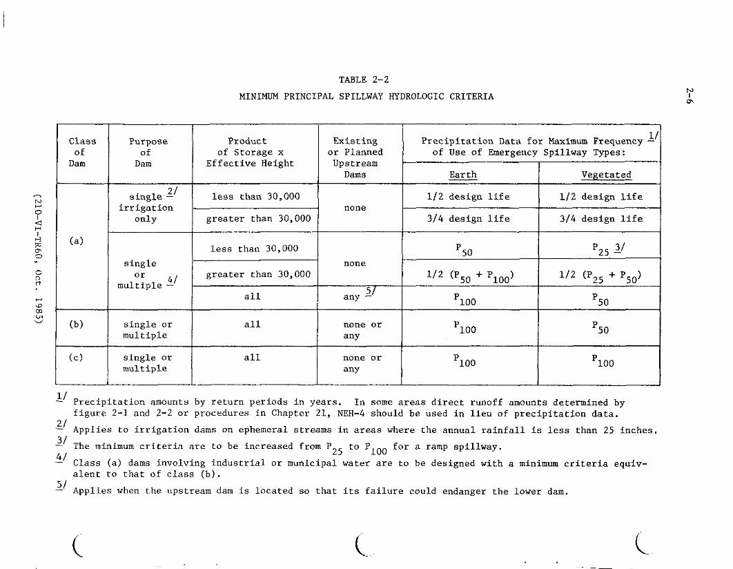
( (
TABLE 2-5
MINIMUM EMERGENCY SPILLWAY HYDROLOGIC CRITERIA
Class Product Existing PreciPitation Data for Y of of or Planned Emergency
Dam Storage x Upstream Spillway Freeboard 0 Effective Height Dams Hydrograph Hydrograph lt
H
l less than 30000 none Piao plOO + 012 (PMP - plOO) 0
(a) Jj greater than 30000 none plOO + 006 (PMP - PlOO) plOO + 026 (PMP - plOO)
all any 1 plOO + 012 (PMP - plOO) plOO + 040 (PMP - PlOO)
none (b) all or plOO + Ol2 (PMP - PlOO) PlOO + 040 (PMP - plOO)
any
none0
ct (c) all or plOO + 0bull26 (PMP - PlOO) PMP any
3 _ = Precipitation for 100-year return period PMP = Probable maximum precipitationP100
3 Dams involving industrial or municipal water are to use minimum criteria equivalent to that of class (b) N I
1 Applies when the upstream dam is located so that its failure could endanger the lower dam
~
IgtI-
lt 0
d Hbull
deg0
~
iamp I-
0
rT
I-
~
degdeg0
(_
- bulloobull 9i 90deg osmiddot ~middot
Area I I i Area 2I
0
85
1
- middot 85 I tf~fo
_
middotI
Area 1 Area 2
40bull__
RATIOS FOR 50 AND 25-YEAR 10-DAY RUNOFF VOLUMES
To obtain Multiply map values byArea 1 Area 2 Area 3
50-YEAR 10-DAY RUNOFF 085 090 092 25-YEAA 10-DAY RUNOFF 070 080 085 Area 3
FIGURE 2middot1 (A) lOOmiddotYEAR 10-DAY RUNOFF (INCHES) PRINCIPAL SPILLWAY HYDROGRAPH
JANUARY 1971 REV APRIL 1976 OCTOBER 1990
l (_
( ( (
0
rt
LEGEND
0 1 - 1-Day Volume Runoff
010- 10-Day Volume Runoff
FIGURE 2-1 (B)
RATIOS OF VOLUMES OF RUNOFF (Q 11Q
10)
PRINCIPAL SPILLWAY HYDROGRAPH
JANUARY 1971 REV APRIL 1976
~
shybullOO ~middotmiddot cbull I I deg
IF~ R lt bull
middot~10
~
I Ngt-gt0I
Hlt I I -middot --~~---CUI V-lf-IJ-H
deg~
0
2
R i
rt I3 4
gt-gt
degln ~
Note For Wisconsin Michigan and eastern I
Iowa use csrn values in circles
FIGURE 2middot1 (C) QUICK RETURN FLOW (csm)
PRINCIPAL SPILLWAY HYDROGRAPH
JANUARY 1971 REV APRIL 1976
(_ ( (
( ( (
115deg r
---------~
~
N 0 I
ltl ----- --- H I
H ~ ashy0 I 40deg-_
0 ()
rt
00
~
-------middot-middot40
LEGEND
JltUgtj Pr1mar1ly snowmelt produced floods
CJ Primarily rain produced floods
[=J Deep snowpack areas
FIGURE 2-2 (A)50-YEAR 10-DAY RUNOFF-Use 85 of map value
25middotYEAR IO-DAY RUNOFF-Use 70 of map value 100-YEAR 10-DAY RUNOFF (INCHES)
PRINCIPAL SPILLWAY HYDROGRAPH SNOWMELT PRODUCING FLOOD AREAS ~
January 1971 Rev Apri I 1976 w
I
0(lrt
_ --1()LEGEND
[j Primarily snowmelt produced floods
LJ Primarily rain produced floods
C=J Deep snowpack areas
Q1 - I-Day Volume RunoffQ10 - 10-0ay Volume Runoff FIGURE 2-2 (B)
RATIOS OF VOLUMES OF RUNOFF (Q 1Q10)JANUARY 1971 REV APRIL 1976 PRINCIPAL SPILLWAY HYDROGRAPH SNOWMELT PRODUCING FLOOD AREAS
( ( (shy
t
bull middotf middotmiddot -~
~
N Use Maps in 0 I lt H I
NOAA Atlas 2 (1973-shyfor the middot
1 1
L v -1
ti[amp 6
lt
deg 0 D
0
rt
(Xgt gt
- ~
II I
0 I bull jTechntc~I- cpoundJ -11middot
ulwa~er 43 -uf)_r111962) 1 I -i~ ~ -f---
~ --middot-middot - 11
-shy
middot-~
bullmiddotmiddot
FIGURE 2-3 MINIMUM 100-YEAR PRECIPITATION
Technical Paper 42 6-HOUR 10-SOUARE MILES (inches) USWB (1961
Technical Paper 47 USWB ( 1963)
APRIL 1976 bullmiddot
middot1middot~
~-
~~-t--
-----shylt
~middotimiddot_ middot
c~ )I-middot_ 1)-~I
8 i
bull1f
EMERGENCY SPILLWAY AND FREEBOARD HYDROGRAPHS ---shy~-- - --shy
~~ ~ ~i~~ cbullbull1BOibull~ middot~
~ U1
-- __L I ___ -~-~- -- -~----middot--
SOURCE HYDROMETEOROGICAL REPORT 5 I CAllbullSbullason PMP - I 978)
middot
_1~ middotmiddot
middotmiddotmiddot~~~~middotmiddot-- _-_r---~lt-gt _ -~ ~~_4--7 l 1 + 1J )lt 4e -i--
Z2 f - -middotr gt dmiddotti~~ft_ ~ - shyI
- __ ~ Ji ~
N middotbull SEE FIClUR~ fL~ bull0I
IJlO~ftRE~q of= APPJicABLlIYlt1 bull bull Olt NWSREFltf~fNdES H - i --r -I fI f i _Mk f- iH +~i_middot~ t bull I0deg ~ I ri
rmiddotmiddot f n0 --J t
H bull I I
-J )I iI
cc Lrj
Vgt ~
I
~
Lmiddot-ief
II NOTE It basin areaI - is greaJer than I 0middot ~-4~I
squara_ miles aeeHydrctmet Reports 5 Iamp 52
-_ Stippled ares are regions
FIGURE 2-4 0 where detailed terrain K effects have not beenPROBABLE MAXIMUM PRECIPITATION ~ evaua ted8-HOUR 10-SQUARE MILES (lnchee) ~EMERGENCY SPILL WAY
AND FREEBOABDliYDROGRAPHS32 4-
Aug I 985
( ( c
( ( (
middot1cent pi - _ smiddot efer nmiddotcmiddote -_fbifmiddot __ _ middotz~K ALAKAmiddotmiddotmiddot~~ c-Tec~~i~ per 4middot1 USWB Cl~~middot _ -~~dlpmet gtoglcaReport 54 (I 9~~ middot
1 1
[ HAWAlti~tJNDSlOo~dfmbulli~or~loglcal Rep~rt 39 ( 1963 FIGURE 2-5
~t_PJJ~Rro=RICO -middot~T~ch~cal Rp~rt42 USWB CI t6 PROBABLE MAXIMUM PRECIPITATIONI) and -middotmiddot- -lt-~r -
ivlRGIN ISLANDS f(bull middot middot NWS REFERENCESJUDY REGIONS N I i t~
JI-bull~~i ~~ ~h~-S f middotgt-
I ~~ ~1~J Ii 1 Aug I 9lf5 ~ ~- -_~-middot--~-~- 1 ~-m~___z__~- 1b~--~
N
_I
10 I I 11 I I I 10 ltXgt
~09 1- - 1 TPACIFIC C0iSTA1 CL~AT+- ~ I - ~ t _HUMID 4ND SU 09
a-_z-
OB -------- ---- -f -1 - BHUM10 CLIM4Tf -
~
_ --+ I 4~ + -= I--
_ I D Atvo ~E 07 08
St1i114 -_1 _ - ---- _J__J-- ~-i-i- I--- --- li10 Cl -_0 +-shy~ 06 ~ 11fq f-
lI - ~+- t-r- Pgt
Ir----+-- -- ---- =gt 6 0
c c t+050 15 x20 25 30 35 40 45 50 60 70 BO 90 100DRAINAGE AREA IN SQUARE MILES
0
I~u 0
~ I
_ A) AREAL PRECIPITATION ADJUSTMENTS FOR gt-z gtshy
Z
00DRAINAGE AREAS 10 to 100 SQUARE MILES J ~a ~
H ~~I ~rl
lt~04~ zshylti i0 0i== 00
~~ 00c c
llt o
deg 0 I00 ~~
~ gt-gtshy zz0
0
~
0 2 3 4 5 6~~ TIME IN HOURSzzlti lti (C) SIX HOUR DESIGN STORM DISTRIBUTION0~
FIGURE 2-6 12 18 EMERGENCY SPILLWAY AND FREEBOARD
TIME IN HOURS VOLUME ADJUSTMENTS AND STORM DISTRIBUTION(B) RELATIVE INCREASE IN RAINFALL AMOUNT
FOR AREAS WHERE NWS REFERENCES DO NOTFOR STORM DURATIONS OVER SIX HOURS CONTAIN AN APPLICABLE PROCEDUREAug 1981
(_ ( (
3-1
SEDIMENTATION
Reservoirs used to store or retard water from surface runoff will trap and store a large portion of the sediment in the runoff water Thereshyfore allocate storage capacity for the calculated sediment accumulation during the design life of the reservoir Criteria and general procedures needed to determine the volume required for sediment accumulation and its allocation in the reservoir are contained in NEH-3 Sedimentation and TR 12 The latter also includes procedures for determining
1 The sediment yield for present conditions and for the future after planned land treatment and other measures are applied in the drainage area of the dam
2 The trap efficiency of the reservoir
3 The distribution and types of sediment expected to accumulate
4 The proportion of the sediment that will be continously submerged vs that aerated and
5 The densities to which the sediment will become compacted
__ If the amount of sediment accumulation calculated exceeds two watershed inches in 50 years for the uncontrolled drainage area of the darn reevaluate the entire watershed to determine if more economical methods of reducing sediment yield or trapping sediment may be feasible and applicable
(210-Vl-TR60 Oct 1985)
4-1
GEOLOGIC INVESTIGATIONS
The intensity and detail of geologic site investigations are to be consistent with the class of dam complexity of site geology and the data needed for
design General requirements procedures and criteria are set forth in 210-V Part 531 and NEH-8
Geologic conditions that require special consideration beyond the minimum investigations spelled out in the above reference are
1 Seismic Assessment -- Dams in zones 3 and 4 Alaska Puerto Rico and the Virgin Islands and high hazard [class(c)] dams in zone 2 (see figure 4-1) require special investigations to determine liquefaction potential of noncohesive strata including very thin layers and the presence at the site of any faults active in Holocene time As part of this investigation a map is to be prepa-red showing the location and intens i tr of magnitude of all intensity V or magnitude 4 or greater earthquakes of record and any historically active faults within a 100 kilometer radius of the site (Obtain earthquake information for this map in printout form from the Environmental Data Service attention D62 NOAA Boulder Colorado 80302 Telephone FTS 323-6472 Commercial (303) 499-1000 ext 6472) The report should also summarize other possible earthquake hazards such as ground compaction landslides excessive shaking of unconsolidated soils seiches and in coastal areas tsunamis
2 Subsidence -- Investigate the potential for surface subsidence due to past or future solid liquid (including ground water) or gaseous mineral extraction Consult the state geological andor evaluation National Engineering Manual 210-V Part 531 Subpart D sets forth criteria for these evaluations
Evaluate the impact of the preemption of mineral deposits including sand and gravel by dams and reservoirs
In arid and semiarid areas and in eolean deposits determine the potential of moisture deficient soil materials to collapse upon saturation or wetting If the potential exists make extensive and intensive site investigations to provide quantitative information for design and construction
3 Emergency Spillways -- Large dams with emergency spillways in soft rock or cemented soil materials that cannot be classified as soil as defined Jn TR 52 nor as rock as generally defined for engineering purposes and spillways in rocks with extraordinary defects require a special individu1l evaluation
(210-VI-TR60 Oct 1985)
4-2
4 Mass Movements -- Evaluate landslides and landslide potential at dam and reservoir sites especially those in shales and where unfavorable dipshyslope or other adverse rock attitudes occur Summarize the history of mass movement in the project area Emergency spillway cuts and reservoir effects must be given careful consideration
5 Karstic areas -- Limestone and gypsum in reservoirs and at damsites require special investigational methods and careful evaluation of subsidence leakage hazards and construction costs Multipurpose structures in these areas are especially critical
6 Multipurpose Dams -- Investigate the ground water regime and hydraulic characteristics of the entire reservoir area of water storage dams and evaluate for leakage Use the water budgets to determine the need for reservoir sealing
7 Other -- Special studies and evaluations may be necessary where such things as compaction shales some types of siliceous calcareous or pyritic shales rebound joints dispersed soils or artesian waters occur at a site
(210-VI-TR60 Oct 1985)
( (
0 I lt I
rel ll
0 0 () rt
00 U1 deg
Minimum Seismic Coefficients
Zone Coefficients-0shy
1 005 2 010
3amp4 Base on Seismic Assessment
0 Q
SEISMIC ZONE MAP of
CONTIGUOUS STATES f w
0
Q
l
Adapted From TM 5-809-10 NAVFAC P-355 AFM 88-3 Chapter 13 April 1973
f KAUAI
~ 8LIHUE
OAHU ocE~N NllHAU
~ HONOLULU
MOLOKAI I----
KAUN~
LANAI Cl~~ ~
N ~
0 P~c1f c bullLANAI I
lt1 H KAHOOLAWE I gt-l_ 10 0 10 20 30 40
deg STATUTE MILES 0 0 (l rt
bullHILO ~ MinimlDil Seismic Coeficients 00 Ln ~
gt-bull OQ
Zone Coefficients
ro 0 0
1 005 I
gt- 2 010
romiddot ro
3amp4 Base on Seismic Assessment
rt
SEISMIC ZONE MAP 0
Hawaii
Adapted From TM 5-809-10 NAVFAC 0-355 AFM 88-3 Chapter 13 April 1973
( ( (
5-1
EARTH EMBAlKMENTS AND FOUNDATIONS
Earth embankments constructed of soil and rock are the principal means of impounding water The earth embankment and its foundation are to withstand the anticipated loads without movements leading to failure Measures are to be provided for adequate seepage control
Height
The design height of an earth embankment is to be sufficient to prevent overshytopping during passage of either the (1) freeboard hydrograph or (2) the emergency spillway hydrograph plus the freeboard required for frost condishytions or wave action whichever is larger The design height must also meet the requirements for minimum emergency spillway depth The design height of the dam is to be increased by the amount needed to compensate for settlement
Top Width
The minimum top width of embankment is shown in Table 5-1
Table 5-1
Minimum Top Width of Embankment
Total Height of Embankment
(feet) (H) All
Dams
Top Width Single Purpose
Floodwater Retarding
(feet) Multipurpose
or other Purposes
14 or less 8 15 - 19 10 NA NA 20 - 24 12 25 - 34 14
H + 35 35 - 95 NA 14 5 Over 95 NA 16 26
The width may need to be greater than the above minimums to (1) meet state and local standards (2) accommodate embankment zoning (3) provide roadway access and traffic safety and (4) provide structural stability An increase in top width is a major design feature in preventing breaching after embankshyment slumping caused by earthquake ground motion
When the embankment top is used as a public roadway the minimum width is to be 16 feet for one-way and 26 feet for two-way traffic Guardrailsmiddot or other safety measures are to be used and are to meet the requirementsof the responsible road authority
(210-VI-TR60 Oct 1985)
5-2 Embankment Slope Stability
Analyze the stability of embankment slopes using generally accepted methods based on sound engineering principles Document all analyses or considerations in appropriate design reports and files Design the embankment cross section to provide adequate factors of safety against sliding sloughing or rotation in the embankment and foundation Use the appropriate degree of conservatism in the analysis that is consistent with the adequacy of the site investigation and soil testing program and with the complexity of the site and consequences of failure Minimum factors of safety are listed in table 5-2
Evaluate the effect of seismicity on each site Include the determination of whether the site is in a seismically active area its proximity to active faults and the predicted site ground motion intensity Use the minimum seismic coefficient shown in Figure 4-1 in the slope stability analysis when no special seismic assessment is made
Analyze embankment slope stability for the conditions and periods during the design life of the structure that are most critical or severe Use conditions in the analysis based on possible critical water levels and loadings of the embankment and foundation Consider and document the following conditions or periods (1) end of construction (2) steady seepage (3) rapid drawdown and (4) during seismic loading Use the shear strength parameters and minimum factors of safety indicated in Table 5-2 for each case The nomenclature for the various shear strength tests is listed in Table 5-3
Calculate the factor of safety based on the ratio of the shear strength available to the shear strength mobilized
Clearly document the conditions not analyzed correlated shear strength parameters or correlation to field performance
Consider the following additional details in conjunction with Table 5-2
I End of Construction Make a detailed analysis of this case when significant pore pressure development during construction is expected in either the embankment or foundation soils Embankment soils are to be tested at the highest likely placement water content and foundation soils are to be tested at saturation Select shear strength parameters according to Table 5-2
II Rapid Drawdown Analyze the stability of the upstream embankment slope for the condition created by a rapid drawdown of the water level in the reservoir Use a phreatic surface in the embankment developed from the emergency spillway crest with the water level in the reservoir drawn down to the crest of the lowest gated or ungated outlet Failure surfaces are to be confined to the embankment only if foundation soils are free-draining Use infinite slope stability equation appropriate to drainage conditions of the embankment soils whenever the c or c value being used in the analysis is zero In addition to the infinite slope analysis circular arch or sliding wedge analyses may be needed to check stability where failure surfaces could extend into weaker core
(210-VI-TR60 Oct 1985)
5-3
zones or into the foundation Select shear strength parameters according to Table 5-2
III Steady Seepage Without Seismic Forces Analyze the downstream slope for the condition of steady seepage developed from the water surface at the principal spillway crest In the analysis saturated soils will be subjected to uplift forces simulated by a piezometric surface developed from the emergency spillway crest Phreatic surfaces and piezometric surfaces may be developed using flow nets or Casagrande procedures Select shear strength parameters according to Table 5-2
IV Steady Seepage With Seismic Forces Analyze the downstream slope for the condition of steady seepage developed from the water surface at the principal spillway crest with a horizontal force equal to the effective weight multiplied by the earthquake coefficient applied at the failure surface (pseudo-static analysis) Uplift forces due to the reservoir at the emergency spillway level need not be included because of the very remote potential for the simultaneous occurrence of an earthquake and an emergency spillway storm event A two or three dimensional computer analysis may be used instead of a pseudo-static analysis if desired Select shear strength parameters according to Table 5-2
V Steady Seepage With and Without Seismic Forces Determine the results of the analysis using either the total stress or effective stress shear strength parameters that are the most limiting (those resulting in the lowest factor of safety) Analyses are to include the use of various combinations of total stress parameters in certain zones and effective stress parameters in other zones The combinations that may be most limiting can usually be narrowed to one or two by inspection and judgement without analyzing all possible combinations
VI Additional Guidance
A Effective stress shear strength parameters are generally the most limiting for any free draining soil
B Total stress shear strength parameters are generally most limiting for non-free draining foundation soils that exhibit positive pore pressure buildup during undrained shear testing
C Effective stress shear strength parameters are generally most limiting for non-free draining foundation soils that exhibit negative pore pressure buildup during undrained shear testing
D Analyses will generally have to be made using both total and effective stress shear parameters to determine the most limiting for non-free draining embankment soils that exhibit either small negative or positive pore pressures during undrained shear testing
E Effective stress shear strength parameters are generally most limiting for non-free draining embankment soils that exhibit highly negative pore pressures during undrained shear testing
F Total stress shear strength parameters are generally most limiting for non-free draining embankment soils that exhibit highly positive pore pressures during undrained shear testing
(210-VI-TR60 Oct 1985)
TABLE 5-2 SLOPE STABILITY CRITERIA FOR DAMS
Design Condition Primary Assumption Remarks Minimum Factor ___o_f__s a tot v
I bull End of construcshytion (upstream or downstream slope)
Significant construction pore pressures expected in cert a In zones of the embank~
ment or layers In the foundation
1
2
Embankment conshyta In 1ng Impershyvious sol Is at water contents aqua I to or greatagtr than optimum water content andor Saturated Impershyvious foundation strata too thick to tully consolishydate duriog construction
uu I 4 ( 13 ls acceptshyable for embankshyments on strong foundations Ie the fal lure surshyf ace Is I ocated entirely In the embankment)
Peryen1ous embankment zones andor foundashyt I on strata
CiT or CD
I I Rapid drawdown (upstream slope)
Drawdown sp 111 way
from the crest to
emergency the crest
Fa 11 ure surface can be confined to the
Use alternative I or 2 below -
1 2
of the ungated
lowest gated outlet
or embankment or extend Into the foundation 1 Lowest shear If low permeability sol ls are Involved
strength from composite enveshylope of CU and CiT
or
2 Most IJr_ltlng3 of CU or CU or a combination ot both
(For alternative 2 only use shear strength tat lure crterle ot 01+03 maximum for dilative soils tested with backpressure saturation techniques This Is to avoid rel lance on high coh~shyslon developed by negative pore presshysure as a result of water tension)- --~-------------------middotmiddot-middot--------------- ---------------middot------ ___________________________
NOTE See bottom of next sheet tor explanatfon of footnotes
(210-VI-TR60 Oct 1985)
(_
( ( (
TABLE 5-2 (Contd) SLOPE STABILITY CRITERIA FOR DAMS
Design Condition Primary Assumption Remarks Shear strength Minimum Factor To Be Used 12 of Safety-
I I I bull Steady seepage I bull Water surf ace at the Fal lure surface con- nr or CD 1 bull 5 without seismic principal spillway f In ed to the embank-forces (down- crest and phreatic ment on I y stream s 1ope) surface f u I I y developed
through the embankment
2 Plezometrlc surface for Fal lure surface Most I Jmitlng3 of cu 1 bull 5 estimating up I If t In extends Into the or m or a comb Ina-saturated so I I zones Is foundation tlon of both determined with water level at the emergency spillway crest
IV Steady seepage 1 bull Water surface at The Fal lure plane may be Most I imlting3 ot CU 1 bull 1 with seismic crest of the principal cont I ned to the or C1T or a comblnashyforces Cd own- spi 1 lway and phreatlc embankment or may tlon of both stream slope) surface f u I I y developed extend Into the
through the emban-kment foundation
1 Use CU or CD shear strength tor pervlous sol I zones within the foundation or embankment
2 Use Infinite slope stabl I lty analysis whenever the C or C Intercept strength Is zero tor so I Is that are -tested to simulate low cont In Ing pressures This situation exists for tal lure surfaces located near the embankment surface Minimum factor ot safety for the Infinite slope stability analysis Is 11
3 Most llmltlng Is the combination resulting In the lowest factor ot safety
n I
n
(210-VI-TR60 Oct 1985)
5-6
TABLE 5-3
NOMENCLATURE OF SHEAR STRENGTH TESTS
Test Parameters scs Common Condition Obtained Descriltion Abbreviation
Unconsolidated Total Y uu Q Undrained Stress
Consolidated Total Y cu R Undrained Stress
Consolidated Effective _I cu R Undrained with Stress pore pressures measured
Consolidated Effective Y CD ii s Drained Stress
ll Total stress shear strength parameters are determined when no drainage is allowed during the test using the external stresses imposed on the soil specimen When used in a total stress analysis the assumption made is that the pore pressure developed (negative or positive) during loading is the same in the laboratory as it is in the field
_I Effective stress parameters are determined from undrained tests by using the intergranular stresses (total stress minus the pore water stress) on the soil particles When used in an effective stress analysis any effects of pore pressure development (positive or negative) resulting from load application must be accounted for in the analysis
ii The CD tests allow drainage during load application If the load is applied slow enough complete drainage occurs so that no pore pressure develops and the shear strength parameters obtained should be the same as CU parameters
(210-VI TR60 Oct 1985)
5-7
Seepage
To the extent needed an analysis is to be made of anticipated seepage rates and pressures through the embankment foundation abutments and reservoir perimeter (when storage is desired) Controls and treatment should be adequate to (1) accomplish the intended reservoir function (2) provide a safely operating structure and (3) prevent damage to downstream property
Zoning
Embankment zoning can be used when needed to (1) obtain a stable structure with the most economical use of available materials (2) control seepage in a safe manner or (3) reduce to a minimum the uncertainties of material strengths and resultant stability
Embankment zones should be a minimum of 10 feet wide except for filters and drains with specified and controlled gradation Drains and filters should meet the requirements contained in Soil Mechanics Notes
Soil materials which exhibit significant shrinkage swell or dispersion are to be used only with extreme care If possible they should not be used for embankment construction When there is no economical alternative to their use they are to be (1) treated to improve their performance (2) placed in zones where effects will not be detrimental or (3) protected by use of filters and drains or self-healing transition zones
Surface Protection
Embankment surfaces are to be protected against surface erosion Protection may be vegetative gravel rock riprap soil cement structural or similar treatment of durable quality and proven satisfactory performance
Vegetative Protection Vegetative protection may be used on surfaces where the following conditions can be met (1) inundation of the surfaces is of such frequency that vegetative growth will not be inhibited (2) vigorous growth can be sustained under average climatic conditions by normal maintenance without irrigation and (3) stable protection can be designed according to the procedures in TR-56
Structural Protection Protection against wave erosion by riprap or other structural measures is to be provided as follows (1) for dams where vegetation will not provide effective control (2) for multiple purpose dams and (3) for dams with fluctuating normal water levels
Protection is to extend from the lowest drawdown elevation that presents an erosion hazard to a few feet above the crest of the lowest ungated spillway The upper limit is to be based on an analysis of anticipated wave height and run up
Quality of riprap and other structural protection is to be consistent with the anticipated life of the dam and designed to be structurally stable
(210-VI TR60 Oct 1985)
6-1
PRINCIPAL SPILLWAYS
The structural design and detailing of principal spillways are to conform to the recommendations of National Engineering Handbook Section 6 Structural Design and SCS standard drawings All component parts of principal spillways except easily replaceable parts such as gates and trash racks are to be equally durable
Capacity of Principal Spillway
The required capacity of the principal spillway depends on (1) purpose of the dam (2) the amount of storage provided by the retarding pool (3) the kind of emergency spillway (4) stream channel capacity and stability downstream (5) potential damage from prolonged storage in the retarding pool (6) potential damage downstream from prolonged high outflow rates (7) possibility of substantial runoff from two or more storms in the time required to empty the retarding pool (8) limitations imposed by water rights or other legal requirements (9) environmental concerns (10) planned or potential alterations of the channel downstream and (11) the necessity to pass base and flood flows during construction
The principal spillway may be single-stage having an ungated inlet at only one elevation or multiple-stage having inlets at two or more elevations In the case of multiple-stage spillways the lower stage or stages usually perform the primary flood control function and the high stage has the capacity needed to prevent the emergency spillway from functioning more frequently than permissible
The principal spillway capacity should be adequate to empty the retarding pool in 10 days or less This requirement is considered to be met if 15 percent or less of the maximum volume of retarding storage remains after 10 days Where low release rates are required to meet the objectives of the project a longer period than 10 days may be needed For these situations additional storage is required to minimize the opportunity for increased frequency of emergency spillway flow due to recurring storms
Compute the 10-day drawdown from the time the maximum water surface elevation is attained during the passage of the principal spillway hydrograph The entire design inflow hydrograph including quick return flow upstream releases and outflow are to be considered in determining the evacuation time of the retarding storage The inflow from storm runoff must be considered for the entire evacuation time
For dams where more than 15 percent of the retarding storage volume remains after 10 days the elevation of the crest of the emergency spillway will be raised The raised crest elevation is determined by adding the remaining retarding storage volume to the initial retarding storage volume
(210-Vl-TR60 Oct 1985)
6-2
Elevation of Principal Spillways
Single Purpose Floodwater Retarding Dams The crest of the principal spillway or of the low stage inlet of a two-stage principal spillway is to be set at the sediment pool elevation For dry dams the elevation of the principal spillway inlet is to be placed as described above and provisions are to be made to drain the reservoir in a reasonable time and thus satisfy the functional or legal requirements of the dam
Other Dams When conservation storage is to be provided the elevation of the crest of the lowest ungated inlet of the principal spillway is to be determined by the volume area or depth of water required for the planned purpose or purposes and the required sediment storage The lowest crest may be the crest of the low-stage inlet single-stage inlet or an open spillway
Routing of Principal Spillway Hydrographs
Reservoir flood routing used to proportion dams and associated spillways is to be based on the assumption that all sedimentation expected in the reservoir during its design life has occurred The reservoir stage-storage curve used for routing should reflect the anticipated accumulation of sediment The initial reservoir stage for principal spillway hydrograph routing is to be at the crest of the lowest ungated inlet or (if not subtracted from the stage-storage curve) the anticipated elevation of the sediment storage whichever is higher except as provided in items 1 2 and 3
1 For dams with significant base flow principal spillway hydrograph routings must start not lower than the elevation of the water surface associated with the base flow Significant base flow is average annual or seasonal flow that would produce at least 05 feet of head over the lowest principal spillway inlet immediately prior to a flood or occupy more than 10 percent of the floodwater storage capacity
2 For dams with joint use storage capacity when one of the uses is floodwater detention routing of the principal spillway hydrograph may begin at the lowest anticipated elevation of the joint use pool in accordance with the operation plan
3 Single purpose class (a) irrigation dams with gated outlets and earth or vegetated emergency spillways which are located on ephemeral streams in areas where the average annual precipitation is less than 25 inches may be considered to have discharged up to 70 percent of the storage exculsive of sediment storage in determining the elevation to start routing
Design of Principal Spillways
Hydraulics The principal spillway is to be designed to carry the planned flow for expected head and tailwater conditions TR-29 Design Note No 8 NEH-5 the Engneering Field Manual for Conservation Practices and other appropriate references are to be used for hydraulic design
(210-VI-TR60 Oct 1985)
6-3
Risers Risers for drop inlet spillways are to be designed to maintain the reservoir pool level at or near the inlet crest elevation during low flow periods to establish full pipe flow at as low a head over the crest as practical and to operate without excessive surging noise vibration or vortex action at any reservoir stage Ibis requires the riser to have a larger cross sectional area than the conduit Standard risers have an inside width equal to the width (diameter) D of the conduit and an inside length equal to three times the width (diameter) of the conduit (D x 3D cross section)
Risers are to be designed to exclude trash too large to pass freely through the spillways including the outlet structure and to facili shytate the passage of smaller trash Standard D x 3D risers tend to line up longer pieces of trash and facilitate their passage into and through the conduit Covered risers with standard skirted or baffle inlets should be used in most cases because they are most effective in excluding trash without becoming clogged Skirted inlets having a cover with skirts extending below the weir crest elevation are applicable where backfill or settlement levels are to be at least two times the conduit width (diameter) below the crest Baffle inlets are applicable for risers that are to be backfilled to the crest eleshyvation or where sediment is expected to build up to the crest elevation
Risers are to be designed structurally to withstand all water earth ice and earthquake loads to which they may be subjected Articulation is to be provided to allow movement of the riser with respect to the conduit
Risers with low-stage inlets at or near the bottom are to be provided with concrete aprons to prevent erosion of soil and undermining of the riser footing by high velocity flow approaching the inlet
Standard risers are to be used where applicable for class (a) dams with an effective height of more than 35 feet and for all class (b) and class (c) dams Prefabricated pipe risers are permissible where hydraulically and structurally adequate for class (a) dams not more than 35 feet in effective height The riser pipe is to be of the same material as the conduit and at least one standard pipe size larger then the conduit pipe
Special riser designs are required for spillways having maximum conduit velocities more then 30 feet per second and for spillways having conduits larger then 48 inches in width (diameter) Generally these should be similar to standard risers but a special elbow and transition is required at the junction of the riser and conduit and special design of the inlet may be necessary Hydraulic model testing should be considered if the maximum total head on the spillway is more than 75 feet or the conduit velocity exceeds 50 feet per second
(210-Vl-TR60 Oct 1985)
6-4
Conduit The conduit should be straight in alignment when viewed in plan Changes from straight alignment if required are to be accomplished by watertight angle changes at joints or by special elbows having a radius equal to or greater than the diameter or width of the conduit Thrust blocks of adequate strength are to be provided if special pipe elbows are used They are to be designed to distribute the thrust due to change in direcshytion for the maximum possible discharge Drop inlet conduits are to be installed with enough slope to insure free drainage to the outlet of all parts of the conduit (including camber) at the time of construction and under the maximum anticipated settlement
All condbull1its under earth embankments are to support the external loads with an adequate factor of safety They are to withstand the internal hydraulic pressures without leakage under full external load and settlement They are to convey water at the design velocity without damage to the interior surface of the conduit
Principal spillway conduits under earth dams may be designed to support fill heights greater than the original constructed height if there is a reasonable possibility that the embankment height may be raised later to incorporate additional storage for some approved beneficial use
Rigid principal spillway conduits are to be designed as positive projecting conduits in accordance with the principles and procedures given in TR-5
Principal spillway conduits are to be of reinforced concrete pressure pipe or cast-in-place reinforced concrete unless corrugated steel or welded steel pipe is used in accordance with subsection 2 which follows
Cast-in-place rectangular reinforced concrete conduits are to be designed in accordance with principles and procedures in TR-42 TR-45 or other appropriate design aids
For Reinforced Concrete Water Pipe - - Steel Cylinder Type Prestressed ~eting specification AWWA C301 the 3-edge bearing strength at the first 0001-inch crack is to be used with a safety factor of at least one
For Reinforced Concrete Water Pipe - - Steel Cylinder Type Not Prestressed meeting specification AWWA C300 for Reinforced Concrete Water Pipe -Noncylinder Type Not Prestressed meeting specification AWWA C302 and for other types of reinforced concrete pipe the 3-edge bearing strength at the first 001-inch crack is to be used with a safety factor of at least 133
Elliptical or other systems of reinforcement requiring special orientation of pipe sections are not permitted in spillway conduits
Reinforced concrete pipe is to be designed to support at least 12 feet of earth fill above the pipe at all points along the conduit
(210-VI-TR60 Oct 1985)
6-5
1 Reinforced Concrete Pipe - (A) Minimum Inside Diameters on Yielding Foundations Class (a) dams The minimum diameter of the principal spillway conduit is to be 30 inches unless a joint extension safety margin of at least 15 inches is used in which case the minimum diashymeter is to be 18 inches for maximum fill heights up to 50 feet at the centerline of the dam and 24 inches for greater fill heights
Class (b) dams The minimum diameter of the principal spillway conduit is to be 30 inches unless a joint extension safety margin of 15 inches is used in which case the minimum diameter is to be 24 inches
Class c) dams The minimum diameter of the principal spillway conduit is to be 30 inches
(B) Minimum Inside Diameters on Non-Yielding Foundations The minimum diameter of the principal spillway conduit for class (a) dams is to be 18 inches for heights up to 50 feet at the centerline of the dam and 24 inches for heights greater than 50 feet and 24 inches for all class (b) and (c) dams The conduit and cradle or bedding are to rest directly on firm bedrock thick enough so that there is essenti shyally no foundation consolidation under the conduit Under these conditions the cradle or bedding under the conduit need not be articulated
2 Corrugated Steel Pipe or Welded Steel Pipe - Principal spillways of corrugated steel or welded steel pipe may be used for single purpose class (a) dams with the product of storage times effective height of dam less than 10000 While installation costs of steel pipes may be less concrete may compare favorably with steel when replacement costs and associated problems are considered
In each case the following limitations apply
a Diameter of pipe not less than 18 inches b Height of fill over the pipe not more than 25 feet c Provision for replacement if the materials will not
last for the design life of the structure d Pipe structurally strong enough to withstand outside
loads and hydraulic pressure e Pipe Watertight
Corrugated steel pipe is to be close riveted asbestos treated and asphalt coated with watertight connecting bands The minimum gage is to be that designed for 35 feet of fill over the pipe
Welded steel pipe conduits are to be structurally designed as rigid pipe A joint extension safety margin of 15 inches is to be provided for conduits on yielding foundation Welded steel pipe is to be protected by a Class A exterior coating as defined in the specifications guide for steel irrigation pipeline Engineering Practice Standard 432-F (NEH-2) or by an exterior coating of coal tar-epoxy paint conforming to Paint System I Construction Specification 82 (NEH 20)
(210-VI-TR60 Oct 1985)
Joints between lengths of corrugated steel or welded steel pipe other than welded joints are to be electrically bridged on the outside of the pipe with insulated copper wire 6 AWG or larger securely attached to the uncoated pipe metal at both sides of the joint This requirement applies whether or not the cathodic protection is completed by the installation of anodes etc The wire s hould have a tough waterproof insulation designed for direct burial with a rating of at least 600 volts Bare wire and exposed pipe metal at the points of connection are to be thoroughly coated with a coating equivalent to the original pipe coating to prevent the entry of moisture
Soil investigations for resistivity and pH of the subgrade and backfill materials to be adjacent to the condui t are to be made The resis t ivity measurements are to be made on saturat ed samples
Cathodic protection is to be provided for welded steel pipe conduits according to the criteria in Engineering Practice Standard 432-F (NEH-2) and 432-F specifications guide
Cathodic protection meet i ng the above r equirements i s to be provided for corrugated steel pipe in soil whose resistivity in a saturated condition is less than 4000 ohms-cm or whose pH is lower than 5 0
If cathodic protection is not required according to the above criteria and anodes are not installed during construction of the dam pipe- to-soil potentials are to be measured within the first 2 years after construction or after the water level has stabilized and when t he soil around the conduit is estimated to be at its normal post-construction moisture content Cathodic protection is to be installed at this time if such measurements indicate it is needed
Joints Conduit joints are to be des i gned and constructed to remain watertight under maximtun anticipated hydrostatic head and maximum probab l e joint opening as computed from Standard Drawing ES- 146 and r e l ated procedures of TR 18 including the effects of joint rotation and the required margin of safety The required joint extensibility is equal to the unit horizontal strain in the earth adjacent to the conduit multipl i ed by the length (in inches) of the section of conduit between joints plus the extension (in inches) due to calculated joint rotation plus a margin of safety
A margin of safety of not less than 05 inch shall be used The required joint extensibility plus the maximum permissible joint gap equals the required joint length The required joint extensibility depends on the maximum
potential foundation consol i dation under the spillway barrel For class (b) and (c) dams the consolidation is to be estimated f r om adequate founshydation borings and samples soil mechanics l aboratory tes ts and engineering analysis For class (a) dams where undis turbed foundation samples are not taken for other purposes approximate procedures based on soil classification and experience may be used for estimating foundation consolidation
(210-VI-TR60 Oct 1985)
6-7
Only joints incorporating a round rubber gasket set in a positive groovewhich will prevent its displacement from either internal or external pressure under the required joint extensibility are to be used on precast concrete pipe conduits Concrete pipe must have steel joint rings providing rubber to steel contact in the joint
Articulation of the conduit (freedom for required rotation) is to be provided at each joint in the conduit at the junction of the conduit with the riser and any outlet structure Concrete bedding for pipe conduits need not be articulated Cradles are to be articulated if on yielding foundations Welded steel pipe conduits need not be articulated if the pipe and bedding rest directly on firm bedrock
Piping and Seepage Control - Use a filter and drainage diaphragm around any structure that extends through the embankment to the downstream slopeDesign the diaphragm with single or multizones to meet the requirements of Soil Mechanics Note No 1
Locate the diaphragm aligned approximately parallel to the centerline of the dam or approximately perpendicular to the direction of seepage flow Extend the diaphragm horizontally and vertically into the adjacentembankment and foundation to intercept potential cracks poorly compactedsoil zones or other discontinuities associated with the structure or its installation
Design the diaphragms to extend the following minimum distances from the surface of rigid conduits
l Horizontally and vertically upward 3 times the outside diameter of circular conduits or the vertical dimension of rectangular box conduits except that
a the vertical extension need be no higher than the maximum potential reservoir water level and
b the horizontal extension need be no further than 5 feet beyond the sides and slopes of any excavation made to install the conduit
2 Vertically downward
a for conduit settlement ratios (o) of 07 and greater (reference SGS Technical Release No 5) the greater of (l) 2 feet or (2) 1 foot beyond the bottom of the trench excavation made to install the conduit Terminate the diaphragm at the surface of bedrock when it occurs within this distance Additional control of general seepage through an upper zone of weathered bedrock may be needed
b 15 times the outside diameter of circular conduits or the outside vertical dimension of box conduits for conduit settlement ratios (o) less than 07
(210-VI-TR60 Revised Amend 1 Oct 1990)
6-8
Design the diaphragms to extend in all directions a minimum of 2 times the outside diameter from the surface of flexible conduits except that the diaphragm need not extend beyond the limits in la and lb above nor beyond a bedrock surface beneath the conduit
Provide minimum diaphragm thickness of 3 feet and minimum thickness of 1 foot for any zone of a multizone system Use larger thickness when needed for (1) capacity (2) tieing into embankment or foundation drainage systems (3) accommodating construction methods or (4) other reasons
For homogeneous dams locate the diaphragm in the downstream section of the dam such that it is
1 Downstream of the cutoff trench
2 Downstream of the centerline of the dam when no cutoff trench is used and
3 Upstream of a point where the embankment cover (upstream face of the diaphragm to the downstream face of the dam) is at least one-half of the difference in elevation between the top of the diaphragm and the maximum potential reservoir water level
For zoned embankments locate the diaphragm downstream of the core zone andor cutoff trench maintaining the minimum cover as indicated for homogeneous dams When the downstream shell is more pervious than the diaphragm material locate the diaphragm at the downstream face of the core zone
~ Lt is good practiceto tie these diaphragms into the other drainage systems in the embankment or foundation Foundation trench drains andor embankment chimney drains that meet the minimum size and ~ocation limits are sufficient and no separate diaphragm is needed
Design the minimum capacity of outlets for diaphragms not connected to other drains by assuming the coefficient of permeability (k) in the zone upstream of the diaphragm is 100 times the coefficient of permeability in the compacted embankment material Assume this zone has a cross-sectional area equal to the diaphragm area and the seepage path distance equal to that from the embankment upstream toe to the diaphragm This higher permeability simulates a sealed filtet face at the diaphragm with partially filled cracks and openings in the upstream zone
For channels chutes or other open structures seepage and piping control can be accomplished in conjunction with drainage for reduction of uplift and water loads The drain properly designed to filter the base soils is to intercept areas of potential cracking caused by shrinkage differential settlement or heave and frost action These structures
9 US Government Printing Office 1991 - 282-95740388
(210-VI-TR60 Revised Amend 1 Oct 1990)
- ~ -
6-9
usually require the use of footings keywalls and counterforts and drainage is properly located iDBDediately downstream of these features This drainage when properly designed can control pip1ng and provide significant economies due to the effect on soil loads uplift pressures overturning forces and sliding stability
Outlets
The choice of outlet is to be based on a careful consideration of all site and flow conditions that may affect operation and energy dissipation
1 Cantilever outlet and plunge pools may be installed where their use
a Does not create a piping hazard in the foundation of the structure
b Is compatible with other conditions at the site
Plunge pools are to be designed to dissipate the energy and be stable Unless the pool is to be in bedrock or very erosion resistant materials riprap will be necessary to insure stability Design Note 6 entitled Armored Scour Hole for Cantilever Outlet is to be used for design
Cantilever outlets are to be supported on bents or piers and are to extend a minimum of 8 feet beyond the bents or piers The bents are to be located downstream from the intersection of the downstream slope of the earth embankment with the grade line of the channel below the dam They are to extend below the lowest elevation anticipated in the plunge pool The invert of the cantilever outlet is to be at least 1 foot about the tailwater elevation at maximum discharge
2 SAF basins may be used when there is adequate control of tailwater Use TR-54 for structural design and NEH-14 for hydraulic design
3 Impact basins may be used when positive measures are taken to prevent large debris from entering the conduit TR-49 is to be used for hydraulic design
Trash Racks
Trash racks are to be designed to provide positive protection against clogging of the spillway under any operating level The average velocity of flow through a clean trash rack is not to exceed 25 feet per second under the full range of stage and discharge Velocity is to be computed on the basis of the net area of opening through the rack
If a reservoir outlet with a trash rack or a ported concrete riser is used to keep the sediment pool drained the trash rack or riser is to extend above the anticipated sediment elevation at the riser to provide
(210-VI-TR60 Oct 1985)
for full design flow through the outlet during the design life of the dam The velocity through the net area of the trash rack above the maximum sediment elevation must not exceed 2 feet per second when the water surface in the reservoir is 5 feet above the top of the trash rack or riser inlet
Antivortex Device
All closed conduit spillways designed for pressure flow are to have adequate antivortex devices
High Sulfate Areas
Under certain conditions concrete is susceptible to deterioration from sulfate ions especially those derived from sodium and magnesium sulfates In areas where experience or soil tests indicate the potential for problems the following table will be used for design purposes
Sulfate Concentration (parts per million) Hazard Corrective Measures
0 - 150 Low None
150 - 1000 Moderate Use Type II Cement (ASTM C-150) Adjust mix to protect against sulfate action
1000 - 2000 High Use Type V Cement (ASTM C-150) Adjust mix to protect against sulfate action Use soils in contact with concrete surfaces that are low in sulfates
2000 - up Do not use concrete materials unless measures are taken to protect concrete surfaces from sulfates Product manufacturers should be consulted
Sulfate concentration is for soil water at the concrete surface
7-1
EMERGENCY SPILLWAYS _
Emergency spillways are provided to convey excess water through over or around a dam They are usually open channels excavated in natural earth earthfill rock or constructed of reinforced concrete
Closed Type Spillways
An open channel emergency spillway is to be provided for each dam except as provided below
1 Class (a) dams with a product of storage times the effective height of the dam of less than 10000 - A closed conduit principal spillway havshying a conduit with a cross-sectional area of 12 square feet or more an inlet which will not clog an elbow designed to facilitate the passage of trash and large enough to pass the routed freeboard hydrograph is the minimum acceptable design without an open channel emergency spill shyway The minimum capacity will be taken from Figure 7-1
2 Dams with drainage areas of 10 square miles or less (except those covered by item 1) - A closed conduit principal spillway having a conduit with a cross-sectional area of 20 square feet or more an inlet which will not clog an elbow designed to facilitate the passage of trash and large enough to pass the routed f reeboard hydrograph peak discharge without overtopping the dam is the minimum acceptable design without an open channel emergency spillway In no case is the capacity of the spillway provided to be less than that determined from Figure 7-1
3 Dams with drainage areas greater than 10 square miles (except those covered by item 1) - A closed type primary emergency spillway may be used in lieu of an open channel emergency spillway Drop inlet spill shyways with a standard two-way covered top inlet are to have a minimum unobstructed cross-sectional area of each opening of the conduit of 40 square feet All other closed type primary emergency spillways are to have a minimum unobstructed cross-sectional area of each opening of 80 square feet The ratio of width to height in both cases is to be between 075 and 133 The spillways must be large enough to pass the routed freeboard hydrograph peak discharge without overtopping the dam In no case is the capacity of the primary emergency spillway provided to be less than that determined from Figure 7-1
Spillway Requirements
Capacity of Emergency Spillways Emergency spillways are to be proportioned so they will pass the emergency spillway hydrograph at the safe velocity determined for the site They are to have sufficient capacity to pass the freeboard hydrograph with the water surface in the reservoir at or below the elevation of the design top of the dam In no case is the capacity of the emergency spillway to be less than that determined from Figure 7-1 The minimum difference in
(210-Vl-TR60 Oct 1985)
7-2
elevation between the crest of the emergency spillway and the settled top of the dam is three feet
State law may establish minimum capacity or depth greater than those given above
Elevation of the Crest of the Emergency Spillway Table 2-2 Page 2-6 gives the maximum allowable frequency of use of earth and vegetated emergency spillways The minimum retarding storage volume and the associated principal spillway discharge are to be such that (1) the discharge through the emergency spillway will not occur during the routing of the principal spillway hydrograph and (2) the 10-day drawdown requirement is met or the crest elevation of the emergency spillway is raised as noted on page 6-1 Capacity of Principal Spillway
For earth spillways it refers to sites where peak flows of short duration may be expected and where erosion resistant soils and moderate slopes exist When vegetated spillways are used the sites must have these same characteristics and in addition conditions must be such that vigorous vegetation can be maintained without irrigation When conditions are less favorable emergency spillways are to be designed for less frequent use This may be done by (1) raising the crest elevation (2) increasing the capacity of the principal spillway (3) adding a structural primary emergency spillway or (4) a combination of the above
The maintenance required for the emergency spillway will be increased as the frequency and duration of flow increase Good design requires balancing the spillway maintenance cost against the increased cost of modifying the other elements of the dam to reduce the flow frequency
Emergency Spillway Routings The emergency spillway and the f reeboard hydrographs are to be routed through the reservoir starting with the water surface at the elevation of the lowest ungated principal spillway inlet the anticipated elevation of the sediment storage the elevation of the water surface associated with significant base flow or the pool elevation after 10 days of drawdown from the maximum stage attained when routing the principal spillway hydrograph whichever is higher except as provided in items 1 and 2
1 Dams with gated spillways and joint use storage capacity - Emergency spillway and freeboard hydrograph routings are to be started at or above the elevation of the lowest ungated outlet or at the elevation of the water surface associated with the average annual base flow whichever is higher
2 Single purpose class (a) irrigation dams - Emergency spillway and freeboard hydrograph routings are to be started at or above the water surface elevation of the irrigation storage
(210-VI-TR60 Oct 1985)
7-3
Hydraulic Design The relationship between the water surface elevation in the reservoir and the discharge through the emergency spillway is to be evaluated by computing the head losses in the inlet channel upstream of the control section or if a control section is not used by computing the water surface profile through the full length of the spillway Bernoullis equation and Mannings formula are to be used to evaluate friction losses compute water surface profiles and determine velocities Policy on the selection of n11 values is given in the discussion of the various types of emergency spillways
Structural Stability The spillway is to be investigated analyzed designed and constructed adequately to establish and maintain stability during the passage of design flows without blockage or breaching Excavated open cut spillways arr to have cut and fill slopes in earth and rock which are stable against slmiddotding Cut slope stability is to be evaluated for the long term weathered natural moisture condition and for adverse moisture conditions associated with rapid drawdown from the emergency spillway design discharge
Vegetated and Earth Emergency Spillways
Vegetated and earth emergency spillways are open channels and usually consist of an inlet channel a control section and an exit channel Subcritical flow exists in the inlet channel and the flow is usually supercritical in the exit channel
Vegetated emergency spillways are usually trapezoidal in cross-section and are protected from damaging erosion by a grass cover They are adapted to sites where a vigorous grass growth can be sustained by normal maintenance without irrigation
Earth spillways are used in those areas where vegetative growth cannot be maintained They are similar to vegetated spillways but are designed for lower permissible velocities and less frequent use Normally they will require more maintenance after a flow occurs
Earth and vegetated emergency spillways are designed on the basis that some erosion or scour may be permissible if its occurrence is infrequent if maintenance facilities are provided and the spillway will not breach during passage of the freeboard storm
TR 2 outlines layout procedures and TR 39 contains hydraulic data to be used in the design of vegetated or earth emergency spillways A Mannings n of 004 is to be used for determining the velocity and capacity in vegetated spillways Design velocities in earth spillways will be based on an n value of O 02 but the capacity of earth spillways will be based on an appraisal of the middotroughness condition at the site
Layout Emergency spillways are to be located away from the dam whenever possible Topographic saddles generally make good sites The layout and profile of vegetated or earth spillways is to provide a maximum bulk of material to
(210-VI-TR60 Oct 1985)
~4
provide safety against breaching of the spillway during the passage of the freeboard hydrograph
The inlet channel is to be level for a minimum distance of 30 feet upstream from the control section This level part of the inlet channel is to be the same width as the exit channel and its centerline is to be straight and coincident with the centerline of the exit channel A curved centerline is permissible in the inlet channel upstream from the level section but it must be tangent to the centerline of the level section
The centerline of the exit channel is to be straight and perpendicular to the control section for a distance equal to a least one-half of the maximum base width of the dam Curvature may be introduced below this point if it is certain that the flowing water will not impinge on the dam should the channel fail at the curve
The exit channel is to be as long as reasonably practical but when a control section is used the grade is to be sufficient to insure supercritical flow for all discharges equal to or greater than 25 percent of the maximum discharge through the emergency spillway during the passage of the freeboard hydrograph However the slope in the exit channel need not exceed 4 percent (s = 004 ftft) to meet this requirement
The spillway discharge may be released by an exit channel at a point some distance above the stable grade of the natural stream channel When this is done the discharge is allowed to spread naturally over the existing toposhygraphy and find its way to the channel downstream Since this layout involves no consideration of velocities beyond the exit channel there may be considerable erosion on those reaches not designed on a permissible velocshyity basis
Another approach is to construct a channel from the end of the exit channel to stable grade below In this case the lower constructed channel may be designed with higher velocities than are permissible in the exit channel proper This assumes that erosion in the lower well defined improved channel may be less damaging than that occurring where the flow is permitted to meander over the natural relief before reaching stable grade
In both layouts erosion will occur wherever the permissible velocities are exceeded and maintenance will be required to protect the integrity of the spillway Land rights are to be considered in making the decision on how to handle the return flow to the natural or constructed stream channel downstream from the dam
Stability Design of Earth and Vegetated Earth Spillways Limitations during routing of the emergency spillway hydrograph - The maximum velocity limitations given below for vegetated or earth emergency spillways apply to the exit channel They must not be exceeded in the reach where an exit channel failure might cause the flow to impinge on the toe of the dam The velocity limitations are based on the maximum discharge in routing the emergency spillway hydrograph and the assumption that uniform flow conditions exist in the exit channel
(210-Vl-TR60 Oct 1985)
7-5
Vegetated Emergency Spillways -- When the anticipated average use of a vegetated emergency spillway is more frequent than once in 50 years the maximum permissible velocity will be in accordance with the values given in SCS Technical Publication 61 (SCS-TP-61) Handbook of Channel Design for Soil and Water Conservation The values may be increased 10 percent when the anticipated average use is once in 50 years or 25 percent when the anticipated average use is once in 100 years Table 7-1 summarizes the recommendations of SCS TP-61 Values for grasses or mixtures not shown in the table are to be determined by comparing their characteristics with those shown in the table Where special studies or investigations have been made to determine the permissible velocity for a species soil and site these values may be used in lieu of those shown in Table 7-1
Earth Emergency Spillways -- The permissible velocity in earth spillways will be chosen after consideration of the soils involved the frequency of use of the spillway and other pertinent factors Table 7-2 is taken form Fortier and Scobeys study Permissible Canal Velocities After Aging and may be helpful in determining this velocity The values given for noncohesive soils should not be exceeded unless special studies have demonshystrated that higher velocities are permissible The table is not strictly applicable for cohesive soils since it applies to canal beds that are seasoned (perhaps permitting higher velocities) and subject to continuous flow and for conditions where erosion damage cannot be tolerated (requiring lower velocities)
Ramp Spillways -- Ramp spillways may be used only when a reasonable alternashytive solution is not practicable This type of spillway is not generally favored by the engineering profession and when accepted requires a very conservative design It may be used only on class (a) dams in humid areas where soils and rainfall are such that a vigorous growth of grass can be maintained without irrigation The allowable frequency of use is 100 years the dams must not be in series and the height-storage product cannot exceed 30000 Slope of the exit channel is to be uniform and may not exceed 10 percent (010 ftft) It is to be located to discharge for its full width onto an approximately level flood plain and with the anticipated or constructed plunge pool below the principal spillway not closer than 50 feet from the outside toe of the exterior confining levee Easily eroded soils and soils subject to excessive shrink or swell are not to be used within 3 feet of the wetted perimeter of the ramp spillway
Limitations during routing of the freeboard hydrograph - Emergency spill shyway stability is to be based on gully erosion and formation principles The design is to be such that the spillway will not breach during passage of the freeboard storm The procedures in TR-52 are to be used for design of all spillways including ramp spillways regardless of drainage area
Special Precautions for Class (c) darns -- Special consideration is to be given to the layout of spillways on Class (c) dams to assure the spillway will not breach under the most exteme conditions of flow The length of the exit channel is to be increased to the maximum extent possible so
(210-VI-TR60 Oct 1985)
7-6
that the area most susceptable to erosion is at a considerable distance from the dam Within the limitations of the site the profile of the spillway is to be such that a maximum bulk of material is provided
It is preferable that the flow be confined without the use of levees but when they are necessary they are to be high enough to contain the peak flow of the routed freeboard hydrograph Levees are to be constructed of erosion resistant materials and compacted to the degree necessary to develop this resistance They are to have a top width not less than 12 feet and if not protected with riprap have side slopes not steeper than 3 horizontal to 1 vertical on the side where water flows When constructed on a foundation subject to piping or undermining they are to be keyed into the foundation with a compacted core having a bottom width not less than the top width of the levee and of sufficient depth to reach sound material or to a depth equal to the height of the levee whichever is less
Crest control structures are to be provided to maintain a uniform surface where the soils are highly erodible from on-site runoff and very low flows through the spillway The effective bulk length may be increased by installshying barriers that will effectively stop a gully advancing through the spillshyway Consideration is to be given to the reduction of the duration and volume of flow through the emergency spillway by raising the elevation of the crest of the emergency spillway thereby increasing the volume of storage in the retarding pool An alternate or complementary procedure is to increase the capacity of the principal spillway by means of a two stage inlet of sufficient size to carry an appreciable amount of the outflow hydrograph
Rock Emergency Spillways
Some of the principles used for the layout of earth emergency spillways are applicable to rock emergency spillways Allowable average frequency of use and permissible velocities must be ascertained for the specific site based on a knowledge of the hardness condition durability attitude weathering characteristics and structure of the rock formation An individual appraisal is necessary to detennine the proper roughness coefficient n The design is to be such that the emergency spillway will not breach during passage of the freeboard storm
Structural Emergency Spillways
Reinforced concrete structural spillways are to be designed so that the passage of the freeboard hydrograph will not cause serious damage to the embankment or the structures themselves The configuration of a structural spillway is to be compatible with the foundation conditions at the site the channel stability downstream from the spillway the possible range of tailwater depth and the proximity of the spillway to the embankment The inlet portion of a chute spillway is to consist of a straight inlet a box drop inlet an ogee crest or other appropriate hydraulic structure which will produce critical flow at the crest and result in a determinate stage-discharge relationship
(210-VI-TR60 Oct 1985)
7-7
The hydraulic design of structural emergency spillways is to be in accordance with the principles set forth in NEH-5 Hydraulics NEH-11 Drop Spillways NEH-14 Chute Spillways and US Department of Intershyior Bureau of Reclamation publications or based on model studies with consideration given to the effects of air entrainment by water traveling at supercritical velocities
The design discharge for hydraulic proportioning of structural emergency spillway is to be not less than two-thirds of the planned structure capacity during passage of the routed freeboard hydrograph except that all headwalls and sidewalls are to be designed to prevent overtopping during passage of the full maximum freeboard discharge When the magnitude of a structural emergency spillway exceeds that of structures commonly designed by SCS model studies or other special studies are to be made
The outlet section of concrete chute spillways is to consist of a hydraushylic jump basin such as a SAF deflector bucket roller bucket or other appropriate hydraulic structure which will dissipate the energy of the high velocity discharge
Structura~ emergency spillways are to be designed to withstand lateral earth pressures uplif~ seepage and other hydrostatic and hydrodynamic pressures They are to be structurally designed for the full maximum freeboard discharge with uplift and sliding safety factors of not less than 10 and in accordance with the principles set forth in NEH-6 Structural Design NEH-1~ Drop Spillways and NEH-14 Chute Spillways utilizing TR-50 TR-54 and other appropriate and available design working aids
(210-VI-TR60 Oct 1985)
00
0 o_ 0 CJ
(f)
LL
u
gtshyf-
u lt( 0 lt( u
gtshylt(
s _J _J 0 Ir f
0 (f)
0 rltl bull
l hj -bull
_ I
f-
06 2 3 4 5 10 20 30 40 50 100
DRAINAGE AREA (SQUARE MILES)
Minimum emeroltgtncy spillway capacity - cf s
(
7-9
TABLE 7-1
PERMISSIBLE VELOCITIES FOR VEGETATED SPILLWAYS
Pennissible velocity= feetPer second
Erosion resistant-=- Easily erodiblecent soils soils
Slope of exit channel Slope of exit channel Percent Percent
0 to 5 5 thru 10 0 to 5 5 thru 10
Bermudagrass Bahiagrass 8 7 6 5
Buffalograss 7 6 5 4 Kentucky bluegrass Smooth bromegrass Tall fescue Reed Canarygrass
Sod forming grass-legume 5 4 4 3 mixtures
Lespedeza sericea 35 35 25 25 Weeping lovegrass Yellow bluestem Native grass
mixtures
1 SCS-TP-61
]_ Increase values 10 percent when the anticipated average use of the spillway is not more frequent than once in 50 years or 25 percent when the anticipated average use is not more frequent than once in 100 years
] As defined in TR-52
(210-VI-TR60 Oct 1985) I-_ I
7-10
TABLE 7-2
PERMISSIBLE CANAL VELOCITIES AFTER AGING 1_
Original material excavated Feetsecond
~ine sand non-colloidal 1 5()plusmn_
Sandy loam non-colloidal 175
lilt loam non-colloidal 200 lluvial silts non-colloidal 200
rdinary firm 10C1m 250 olcanic ash 250
ine gravel 250 Stiff clay very colloidal 375
Graded loam to cobbles non-colloidal 375 lluvial silts colloidal 375
Graded silt to cobbles colloidal 400 ~oarse gravel non-colloidal 400
Cobbles and shingles 500 Shales and hardpans 600
1f Recommended in 1926 by Special committee on Irrigation Research American Soiety of Civil Engineers
l_ Values shown apply to clear water no detritus
(210-VI-TR60 Oct 1985)
i-us Government Printing Office 1991 - 282-95740558

~
IgtI-
lt 0
d Hbull
deg0
~
iamp I-
0
rT
I-
~
degdeg0
(_
- bulloobull 9i 90deg osmiddot ~middot
Area I I i Area 2I
0
85
1
- middot 85 I tf~fo
_
middotI
Area 1 Area 2
40bull__
RATIOS FOR 50 AND 25-YEAR 10-DAY RUNOFF VOLUMES
To obtain Multiply map values byArea 1 Area 2 Area 3
50-YEAR 10-DAY RUNOFF 085 090 092 25-YEAA 10-DAY RUNOFF 070 080 085 Area 3
FIGURE 2middot1 (A) lOOmiddotYEAR 10-DAY RUNOFF (INCHES) PRINCIPAL SPILLWAY HYDROGRAPH
JANUARY 1971 REV APRIL 1976 OCTOBER 1990
l (_
( ( (
0
rt
LEGEND
0 1 - 1-Day Volume Runoff
010- 10-Day Volume Runoff
FIGURE 2-1 (B)
RATIOS OF VOLUMES OF RUNOFF (Q 11Q
10)
PRINCIPAL SPILLWAY HYDROGRAPH
JANUARY 1971 REV APRIL 1976
~
shybullOO ~middotmiddot cbull I I deg
IF~ R lt bull
middot~10
~
I Ngt-gt0I
Hlt I I -middot --~~---CUI V-lf-IJ-H
deg~
0
2
R i
rt I3 4
gt-gt
degln ~
Note For Wisconsin Michigan and eastern I
Iowa use csrn values in circles
FIGURE 2middot1 (C) QUICK RETURN FLOW (csm)
PRINCIPAL SPILLWAY HYDROGRAPH
JANUARY 1971 REV APRIL 1976
(_ ( (
( ( (
115deg r
---------~
~
N 0 I
ltl ----- --- H I
H ~ ashy0 I 40deg-_
0 ()
rt
00
~
-------middot-middot40
LEGEND
JltUgtj Pr1mar1ly snowmelt produced floods
CJ Primarily rain produced floods
[=J Deep snowpack areas
FIGURE 2-2 (A)50-YEAR 10-DAY RUNOFF-Use 85 of map value
25middotYEAR IO-DAY RUNOFF-Use 70 of map value 100-YEAR 10-DAY RUNOFF (INCHES)
PRINCIPAL SPILLWAY HYDROGRAPH SNOWMELT PRODUCING FLOOD AREAS ~
January 1971 Rev Apri I 1976 w
I
0(lrt
_ --1()LEGEND
[j Primarily snowmelt produced floods
LJ Primarily rain produced floods
C=J Deep snowpack areas
Q1 - I-Day Volume RunoffQ10 - 10-0ay Volume Runoff FIGURE 2-2 (B)
RATIOS OF VOLUMES OF RUNOFF (Q 1Q10)JANUARY 1971 REV APRIL 1976 PRINCIPAL SPILLWAY HYDROGRAPH SNOWMELT PRODUCING FLOOD AREAS
( ( (shy
t
bull middotf middotmiddot -~
~
N Use Maps in 0 I lt H I
NOAA Atlas 2 (1973-shyfor the middot
1 1
L v -1
ti[amp 6
lt
deg 0 D
0
rt
(Xgt gt
- ~
II I
0 I bull jTechntc~I- cpoundJ -11middot
ulwa~er 43 -uf)_r111962) 1 I -i~ ~ -f---
~ --middot-middot - 11
-shy
middot-~
bullmiddotmiddot
FIGURE 2-3 MINIMUM 100-YEAR PRECIPITATION
Technical Paper 42 6-HOUR 10-SOUARE MILES (inches) USWB (1961
Technical Paper 47 USWB ( 1963)
APRIL 1976 bullmiddot
middot1middot~
~-
~~-t--
-----shylt
~middotimiddot_ middot
c~ )I-middot_ 1)-~I
8 i
bull1f
EMERGENCY SPILLWAY AND FREEBOARD HYDROGRAPHS ---shy~-- - --shy
~~ ~ ~i~~ cbullbull1BOibull~ middot~
~ U1
-- __L I ___ -~-~- -- -~----middot--
SOURCE HYDROMETEOROGICAL REPORT 5 I CAllbullSbullason PMP - I 978)
middot
_1~ middotmiddot
middotmiddotmiddot~~~~middotmiddot-- _-_r---~lt-gt _ -~ ~~_4--7 l 1 + 1J )lt 4e -i--
Z2 f - -middotr gt dmiddotti~~ft_ ~ - shyI
- __ ~ Ji ~
N middotbull SEE FIClUR~ fL~ bull0I
IJlO~ftRE~q of= APPJicABLlIYlt1 bull bull Olt NWSREFltf~fNdES H - i --r -I fI f i _Mk f- iH +~i_middot~ t bull I0deg ~ I ri
rmiddotmiddot f n0 --J t
H bull I I
-J )I iI
cc Lrj
Vgt ~
I
~
Lmiddot-ief
II NOTE It basin areaI - is greaJer than I 0middot ~-4~I
squara_ miles aeeHydrctmet Reports 5 Iamp 52
-_ Stippled ares are regions
FIGURE 2-4 0 where detailed terrain K effects have not beenPROBABLE MAXIMUM PRECIPITATION ~ evaua ted8-HOUR 10-SQUARE MILES (lnchee) ~EMERGENCY SPILL WAY
AND FREEBOABDliYDROGRAPHS32 4-
Aug I 985
( ( c
( ( (
middot1cent pi - _ smiddot efer nmiddotcmiddote -_fbifmiddot __ _ middotz~K ALAKAmiddotmiddotmiddot~~ c-Tec~~i~ per 4middot1 USWB Cl~~middot _ -~~dlpmet gtoglcaReport 54 (I 9~~ middot
1 1
[ HAWAlti~tJNDSlOo~dfmbulli~or~loglcal Rep~rt 39 ( 1963 FIGURE 2-5
~t_PJJ~Rro=RICO -middot~T~ch~cal Rp~rt42 USWB CI t6 PROBABLE MAXIMUM PRECIPITATIONI) and -middotmiddot- -lt-~r -
ivlRGIN ISLANDS f(bull middot middot NWS REFERENCESJUDY REGIONS N I i t~
JI-bull~~i ~~ ~h~-S f middotgt-
I ~~ ~1~J Ii 1 Aug I 9lf5 ~ ~- -_~-middot--~-~- 1 ~-m~___z__~- 1b~--~
N
_I
10 I I 11 I I I 10 ltXgt
~09 1- - 1 TPACIFIC C0iSTA1 CL~AT+- ~ I - ~ t _HUMID 4ND SU 09
a-_z-
OB -------- ---- -f -1 - BHUM10 CLIM4Tf -
~
_ --+ I 4~ + -= I--
_ I D Atvo ~E 07 08
St1i114 -_1 _ - ---- _J__J-- ~-i-i- I--- --- li10 Cl -_0 +-shy~ 06 ~ 11fq f-
lI - ~+- t-r- Pgt
Ir----+-- -- ---- =gt 6 0
c c t+050 15 x20 25 30 35 40 45 50 60 70 BO 90 100DRAINAGE AREA IN SQUARE MILES
0
I~u 0
~ I
_ A) AREAL PRECIPITATION ADJUSTMENTS FOR gt-z gtshy
Z
00DRAINAGE AREAS 10 to 100 SQUARE MILES J ~a ~
H ~~I ~rl
lt~04~ zshylti i0 0i== 00
~~ 00c c
llt o
deg 0 I00 ~~
~ gt-gtshy zz0
0
~
0 2 3 4 5 6~~ TIME IN HOURSzzlti lti (C) SIX HOUR DESIGN STORM DISTRIBUTION0~
FIGURE 2-6 12 18 EMERGENCY SPILLWAY AND FREEBOARD
TIME IN HOURS VOLUME ADJUSTMENTS AND STORM DISTRIBUTION(B) RELATIVE INCREASE IN RAINFALL AMOUNT
FOR AREAS WHERE NWS REFERENCES DO NOTFOR STORM DURATIONS OVER SIX HOURS CONTAIN AN APPLICABLE PROCEDUREAug 1981
(_ ( (
3-1
SEDIMENTATION
Reservoirs used to store or retard water from surface runoff will trap and store a large portion of the sediment in the runoff water Thereshyfore allocate storage capacity for the calculated sediment accumulation during the design life of the reservoir Criteria and general procedures needed to determine the volume required for sediment accumulation and its allocation in the reservoir are contained in NEH-3 Sedimentation and TR 12 The latter also includes procedures for determining
1 The sediment yield for present conditions and for the future after planned land treatment and other measures are applied in the drainage area of the dam
2 The trap efficiency of the reservoir
3 The distribution and types of sediment expected to accumulate
4 The proportion of the sediment that will be continously submerged vs that aerated and
5 The densities to which the sediment will become compacted
__ If the amount of sediment accumulation calculated exceeds two watershed inches in 50 years for the uncontrolled drainage area of the darn reevaluate the entire watershed to determine if more economical methods of reducing sediment yield or trapping sediment may be feasible and applicable
(210-Vl-TR60 Oct 1985)
4-1
GEOLOGIC INVESTIGATIONS
The intensity and detail of geologic site investigations are to be consistent with the class of dam complexity of site geology and the data needed for
design General requirements procedures and criteria are set forth in 210-V Part 531 and NEH-8
Geologic conditions that require special consideration beyond the minimum investigations spelled out in the above reference are
1 Seismic Assessment -- Dams in zones 3 and 4 Alaska Puerto Rico and the Virgin Islands and high hazard [class(c)] dams in zone 2 (see figure 4-1) require special investigations to determine liquefaction potential of noncohesive strata including very thin layers and the presence at the site of any faults active in Holocene time As part of this investigation a map is to be prepa-red showing the location and intens i tr of magnitude of all intensity V or magnitude 4 or greater earthquakes of record and any historically active faults within a 100 kilometer radius of the site (Obtain earthquake information for this map in printout form from the Environmental Data Service attention D62 NOAA Boulder Colorado 80302 Telephone FTS 323-6472 Commercial (303) 499-1000 ext 6472) The report should also summarize other possible earthquake hazards such as ground compaction landslides excessive shaking of unconsolidated soils seiches and in coastal areas tsunamis
2 Subsidence -- Investigate the potential for surface subsidence due to past or future solid liquid (including ground water) or gaseous mineral extraction Consult the state geological andor evaluation National Engineering Manual 210-V Part 531 Subpart D sets forth criteria for these evaluations
Evaluate the impact of the preemption of mineral deposits including sand and gravel by dams and reservoirs
In arid and semiarid areas and in eolean deposits determine the potential of moisture deficient soil materials to collapse upon saturation or wetting If the potential exists make extensive and intensive site investigations to provide quantitative information for design and construction
3 Emergency Spillways -- Large dams with emergency spillways in soft rock or cemented soil materials that cannot be classified as soil as defined Jn TR 52 nor as rock as generally defined for engineering purposes and spillways in rocks with extraordinary defects require a special individu1l evaluation
(210-VI-TR60 Oct 1985)
4-2
4 Mass Movements -- Evaluate landslides and landslide potential at dam and reservoir sites especially those in shales and where unfavorable dipshyslope or other adverse rock attitudes occur Summarize the history of mass movement in the project area Emergency spillway cuts and reservoir effects must be given careful consideration
5 Karstic areas -- Limestone and gypsum in reservoirs and at damsites require special investigational methods and careful evaluation of subsidence leakage hazards and construction costs Multipurpose structures in these areas are especially critical
6 Multipurpose Dams -- Investigate the ground water regime and hydraulic characteristics of the entire reservoir area of water storage dams and evaluate for leakage Use the water budgets to determine the need for reservoir sealing
7 Other -- Special studies and evaluations may be necessary where such things as compaction shales some types of siliceous calcareous or pyritic shales rebound joints dispersed soils or artesian waters occur at a site
(210-VI-TR60 Oct 1985)
( (
0 I lt I
rel ll
0 0 () rt
00 U1 deg
Minimum Seismic Coefficients
Zone Coefficients-0shy
1 005 2 010
3amp4 Base on Seismic Assessment
0 Q
SEISMIC ZONE MAP of
CONTIGUOUS STATES f w
0
Q
l
Adapted From TM 5-809-10 NAVFAC P-355 AFM 88-3 Chapter 13 April 1973
f KAUAI
~ 8LIHUE
OAHU ocE~N NllHAU
~ HONOLULU
MOLOKAI I----
KAUN~
LANAI Cl~~ ~
N ~
0 P~c1f c bullLANAI I
lt1 H KAHOOLAWE I gt-l_ 10 0 10 20 30 40
deg STATUTE MILES 0 0 (l rt
bullHILO ~ MinimlDil Seismic Coeficients 00 Ln ~
gt-bull OQ
Zone Coefficients
ro 0 0
1 005 I
gt- 2 010
romiddot ro
3amp4 Base on Seismic Assessment
rt
SEISMIC ZONE MAP 0
Hawaii
Adapted From TM 5-809-10 NAVFAC 0-355 AFM 88-3 Chapter 13 April 1973
( ( (
5-1
EARTH EMBAlKMENTS AND FOUNDATIONS
Earth embankments constructed of soil and rock are the principal means of impounding water The earth embankment and its foundation are to withstand the anticipated loads without movements leading to failure Measures are to be provided for adequate seepage control
Height
The design height of an earth embankment is to be sufficient to prevent overshytopping during passage of either the (1) freeboard hydrograph or (2) the emergency spillway hydrograph plus the freeboard required for frost condishytions or wave action whichever is larger The design height must also meet the requirements for minimum emergency spillway depth The design height of the dam is to be increased by the amount needed to compensate for settlement
Top Width
The minimum top width of embankment is shown in Table 5-1
Table 5-1
Minimum Top Width of Embankment
Total Height of Embankment
(feet) (H) All
Dams
Top Width Single Purpose
Floodwater Retarding
(feet) Multipurpose
or other Purposes
14 or less 8 15 - 19 10 NA NA 20 - 24 12 25 - 34 14
H + 35 35 - 95 NA 14 5 Over 95 NA 16 26
The width may need to be greater than the above minimums to (1) meet state and local standards (2) accommodate embankment zoning (3) provide roadway access and traffic safety and (4) provide structural stability An increase in top width is a major design feature in preventing breaching after embankshyment slumping caused by earthquake ground motion
When the embankment top is used as a public roadway the minimum width is to be 16 feet for one-way and 26 feet for two-way traffic Guardrailsmiddot or other safety measures are to be used and are to meet the requirementsof the responsible road authority
(210-VI-TR60 Oct 1985)
5-2 Embankment Slope Stability
Analyze the stability of embankment slopes using generally accepted methods based on sound engineering principles Document all analyses or considerations in appropriate design reports and files Design the embankment cross section to provide adequate factors of safety against sliding sloughing or rotation in the embankment and foundation Use the appropriate degree of conservatism in the analysis that is consistent with the adequacy of the site investigation and soil testing program and with the complexity of the site and consequences of failure Minimum factors of safety are listed in table 5-2
Evaluate the effect of seismicity on each site Include the determination of whether the site is in a seismically active area its proximity to active faults and the predicted site ground motion intensity Use the minimum seismic coefficient shown in Figure 4-1 in the slope stability analysis when no special seismic assessment is made
Analyze embankment slope stability for the conditions and periods during the design life of the structure that are most critical or severe Use conditions in the analysis based on possible critical water levels and loadings of the embankment and foundation Consider and document the following conditions or periods (1) end of construction (2) steady seepage (3) rapid drawdown and (4) during seismic loading Use the shear strength parameters and minimum factors of safety indicated in Table 5-2 for each case The nomenclature for the various shear strength tests is listed in Table 5-3
Calculate the factor of safety based on the ratio of the shear strength available to the shear strength mobilized
Clearly document the conditions not analyzed correlated shear strength parameters or correlation to field performance
Consider the following additional details in conjunction with Table 5-2
I End of Construction Make a detailed analysis of this case when significant pore pressure development during construction is expected in either the embankment or foundation soils Embankment soils are to be tested at the highest likely placement water content and foundation soils are to be tested at saturation Select shear strength parameters according to Table 5-2
II Rapid Drawdown Analyze the stability of the upstream embankment slope for the condition created by a rapid drawdown of the water level in the reservoir Use a phreatic surface in the embankment developed from the emergency spillway crest with the water level in the reservoir drawn down to the crest of the lowest gated or ungated outlet Failure surfaces are to be confined to the embankment only if foundation soils are free-draining Use infinite slope stability equation appropriate to drainage conditions of the embankment soils whenever the c or c value being used in the analysis is zero In addition to the infinite slope analysis circular arch or sliding wedge analyses may be needed to check stability where failure surfaces could extend into weaker core
(210-VI-TR60 Oct 1985)
5-3
zones or into the foundation Select shear strength parameters according to Table 5-2
III Steady Seepage Without Seismic Forces Analyze the downstream slope for the condition of steady seepage developed from the water surface at the principal spillway crest In the analysis saturated soils will be subjected to uplift forces simulated by a piezometric surface developed from the emergency spillway crest Phreatic surfaces and piezometric surfaces may be developed using flow nets or Casagrande procedures Select shear strength parameters according to Table 5-2
IV Steady Seepage With Seismic Forces Analyze the downstream slope for the condition of steady seepage developed from the water surface at the principal spillway crest with a horizontal force equal to the effective weight multiplied by the earthquake coefficient applied at the failure surface (pseudo-static analysis) Uplift forces due to the reservoir at the emergency spillway level need not be included because of the very remote potential for the simultaneous occurrence of an earthquake and an emergency spillway storm event A two or three dimensional computer analysis may be used instead of a pseudo-static analysis if desired Select shear strength parameters according to Table 5-2
V Steady Seepage With and Without Seismic Forces Determine the results of the analysis using either the total stress or effective stress shear strength parameters that are the most limiting (those resulting in the lowest factor of safety) Analyses are to include the use of various combinations of total stress parameters in certain zones and effective stress parameters in other zones The combinations that may be most limiting can usually be narrowed to one or two by inspection and judgement without analyzing all possible combinations
VI Additional Guidance
A Effective stress shear strength parameters are generally the most limiting for any free draining soil
B Total stress shear strength parameters are generally most limiting for non-free draining foundation soils that exhibit positive pore pressure buildup during undrained shear testing
C Effective stress shear strength parameters are generally most limiting for non-free draining foundation soils that exhibit negative pore pressure buildup during undrained shear testing
D Analyses will generally have to be made using both total and effective stress shear parameters to determine the most limiting for non-free draining embankment soils that exhibit either small negative or positive pore pressures during undrained shear testing
E Effective stress shear strength parameters are generally most limiting for non-free draining embankment soils that exhibit highly negative pore pressures during undrained shear testing
F Total stress shear strength parameters are generally most limiting for non-free draining embankment soils that exhibit highly positive pore pressures during undrained shear testing
(210-VI-TR60 Oct 1985)
TABLE 5-2 SLOPE STABILITY CRITERIA FOR DAMS
Design Condition Primary Assumption Remarks Minimum Factor ___o_f__s a tot v
I bull End of construcshytion (upstream or downstream slope)
Significant construction pore pressures expected in cert a In zones of the embank~
ment or layers In the foundation
1
2
Embankment conshyta In 1ng Impershyvious sol Is at water contents aqua I to or greatagtr than optimum water content andor Saturated Impershyvious foundation strata too thick to tully consolishydate duriog construction
uu I 4 ( 13 ls acceptshyable for embankshyments on strong foundations Ie the fal lure surshyf ace Is I ocated entirely In the embankment)
Peryen1ous embankment zones andor foundashyt I on strata
CiT or CD
I I Rapid drawdown (upstream slope)
Drawdown sp 111 way
from the crest to
emergency the crest
Fa 11 ure surface can be confined to the
Use alternative I or 2 below -
1 2
of the ungated
lowest gated outlet
or embankment or extend Into the foundation 1 Lowest shear If low permeability sol ls are Involved
strength from composite enveshylope of CU and CiT
or
2 Most IJr_ltlng3 of CU or CU or a combination ot both
(For alternative 2 only use shear strength tat lure crterle ot 01+03 maximum for dilative soils tested with backpressure saturation techniques This Is to avoid rel lance on high coh~shyslon developed by negative pore presshysure as a result of water tension)- --~-------------------middotmiddot-middot--------------- ---------------middot------ ___________________________
NOTE See bottom of next sheet tor explanatfon of footnotes
(210-VI-TR60 Oct 1985)
(_
( ( (
TABLE 5-2 (Contd) SLOPE STABILITY CRITERIA FOR DAMS
Design Condition Primary Assumption Remarks Shear strength Minimum Factor To Be Used 12 of Safety-
I I I bull Steady seepage I bull Water surf ace at the Fal lure surface con- nr or CD 1 bull 5 without seismic principal spillway f In ed to the embank-forces (down- crest and phreatic ment on I y stream s 1ope) surface f u I I y developed
through the embankment
2 Plezometrlc surface for Fal lure surface Most I Jmitlng3 of cu 1 bull 5 estimating up I If t In extends Into the or m or a comb Ina-saturated so I I zones Is foundation tlon of both determined with water level at the emergency spillway crest
IV Steady seepage 1 bull Water surface at The Fal lure plane may be Most I imlting3 ot CU 1 bull 1 with seismic crest of the principal cont I ned to the or C1T or a comblnashyforces Cd own- spi 1 lway and phreatlc embankment or may tlon of both stream slope) surface f u I I y developed extend Into the
through the emban-kment foundation
1 Use CU or CD shear strength tor pervlous sol I zones within the foundation or embankment
2 Use Infinite slope stabl I lty analysis whenever the C or C Intercept strength Is zero tor so I Is that are -tested to simulate low cont In Ing pressures This situation exists for tal lure surfaces located near the embankment surface Minimum factor ot safety for the Infinite slope stability analysis Is 11
3 Most llmltlng Is the combination resulting In the lowest factor ot safety
n I
n
(210-VI-TR60 Oct 1985)
5-6
TABLE 5-3
NOMENCLATURE OF SHEAR STRENGTH TESTS
Test Parameters scs Common Condition Obtained Descriltion Abbreviation
Unconsolidated Total Y uu Q Undrained Stress
Consolidated Total Y cu R Undrained Stress
Consolidated Effective _I cu R Undrained with Stress pore pressures measured
Consolidated Effective Y CD ii s Drained Stress
ll Total stress shear strength parameters are determined when no drainage is allowed during the test using the external stresses imposed on the soil specimen When used in a total stress analysis the assumption made is that the pore pressure developed (negative or positive) during loading is the same in the laboratory as it is in the field
_I Effective stress parameters are determined from undrained tests by using the intergranular stresses (total stress minus the pore water stress) on the soil particles When used in an effective stress analysis any effects of pore pressure development (positive or negative) resulting from load application must be accounted for in the analysis
ii The CD tests allow drainage during load application If the load is applied slow enough complete drainage occurs so that no pore pressure develops and the shear strength parameters obtained should be the same as CU parameters
(210-VI TR60 Oct 1985)
5-7
Seepage
To the extent needed an analysis is to be made of anticipated seepage rates and pressures through the embankment foundation abutments and reservoir perimeter (when storage is desired) Controls and treatment should be adequate to (1) accomplish the intended reservoir function (2) provide a safely operating structure and (3) prevent damage to downstream property
Zoning
Embankment zoning can be used when needed to (1) obtain a stable structure with the most economical use of available materials (2) control seepage in a safe manner or (3) reduce to a minimum the uncertainties of material strengths and resultant stability
Embankment zones should be a minimum of 10 feet wide except for filters and drains with specified and controlled gradation Drains and filters should meet the requirements contained in Soil Mechanics Notes
Soil materials which exhibit significant shrinkage swell or dispersion are to be used only with extreme care If possible they should not be used for embankment construction When there is no economical alternative to their use they are to be (1) treated to improve their performance (2) placed in zones where effects will not be detrimental or (3) protected by use of filters and drains or self-healing transition zones
Surface Protection
Embankment surfaces are to be protected against surface erosion Protection may be vegetative gravel rock riprap soil cement structural or similar treatment of durable quality and proven satisfactory performance
Vegetative Protection Vegetative protection may be used on surfaces where the following conditions can be met (1) inundation of the surfaces is of such frequency that vegetative growth will not be inhibited (2) vigorous growth can be sustained under average climatic conditions by normal maintenance without irrigation and (3) stable protection can be designed according to the procedures in TR-56
Structural Protection Protection against wave erosion by riprap or other structural measures is to be provided as follows (1) for dams where vegetation will not provide effective control (2) for multiple purpose dams and (3) for dams with fluctuating normal water levels
Protection is to extend from the lowest drawdown elevation that presents an erosion hazard to a few feet above the crest of the lowest ungated spillway The upper limit is to be based on an analysis of anticipated wave height and run up
Quality of riprap and other structural protection is to be consistent with the anticipated life of the dam and designed to be structurally stable
(210-VI TR60 Oct 1985)
6-1
PRINCIPAL SPILLWAYS
The structural design and detailing of principal spillways are to conform to the recommendations of National Engineering Handbook Section 6 Structural Design and SCS standard drawings All component parts of principal spillways except easily replaceable parts such as gates and trash racks are to be equally durable
Capacity of Principal Spillway
The required capacity of the principal spillway depends on (1) purpose of the dam (2) the amount of storage provided by the retarding pool (3) the kind of emergency spillway (4) stream channel capacity and stability downstream (5) potential damage from prolonged storage in the retarding pool (6) potential damage downstream from prolonged high outflow rates (7) possibility of substantial runoff from two or more storms in the time required to empty the retarding pool (8) limitations imposed by water rights or other legal requirements (9) environmental concerns (10) planned or potential alterations of the channel downstream and (11) the necessity to pass base and flood flows during construction
The principal spillway may be single-stage having an ungated inlet at only one elevation or multiple-stage having inlets at two or more elevations In the case of multiple-stage spillways the lower stage or stages usually perform the primary flood control function and the high stage has the capacity needed to prevent the emergency spillway from functioning more frequently than permissible
The principal spillway capacity should be adequate to empty the retarding pool in 10 days or less This requirement is considered to be met if 15 percent or less of the maximum volume of retarding storage remains after 10 days Where low release rates are required to meet the objectives of the project a longer period than 10 days may be needed For these situations additional storage is required to minimize the opportunity for increased frequency of emergency spillway flow due to recurring storms
Compute the 10-day drawdown from the time the maximum water surface elevation is attained during the passage of the principal spillway hydrograph The entire design inflow hydrograph including quick return flow upstream releases and outflow are to be considered in determining the evacuation time of the retarding storage The inflow from storm runoff must be considered for the entire evacuation time
For dams where more than 15 percent of the retarding storage volume remains after 10 days the elevation of the crest of the emergency spillway will be raised The raised crest elevation is determined by adding the remaining retarding storage volume to the initial retarding storage volume
(210-Vl-TR60 Oct 1985)
6-2
Elevation of Principal Spillways
Single Purpose Floodwater Retarding Dams The crest of the principal spillway or of the low stage inlet of a two-stage principal spillway is to be set at the sediment pool elevation For dry dams the elevation of the principal spillway inlet is to be placed as described above and provisions are to be made to drain the reservoir in a reasonable time and thus satisfy the functional or legal requirements of the dam
Other Dams When conservation storage is to be provided the elevation of the crest of the lowest ungated inlet of the principal spillway is to be determined by the volume area or depth of water required for the planned purpose or purposes and the required sediment storage The lowest crest may be the crest of the low-stage inlet single-stage inlet or an open spillway
Routing of Principal Spillway Hydrographs
Reservoir flood routing used to proportion dams and associated spillways is to be based on the assumption that all sedimentation expected in the reservoir during its design life has occurred The reservoir stage-storage curve used for routing should reflect the anticipated accumulation of sediment The initial reservoir stage for principal spillway hydrograph routing is to be at the crest of the lowest ungated inlet or (if not subtracted from the stage-storage curve) the anticipated elevation of the sediment storage whichever is higher except as provided in items 1 2 and 3
1 For dams with significant base flow principal spillway hydrograph routings must start not lower than the elevation of the water surface associated with the base flow Significant base flow is average annual or seasonal flow that would produce at least 05 feet of head over the lowest principal spillway inlet immediately prior to a flood or occupy more than 10 percent of the floodwater storage capacity
2 For dams with joint use storage capacity when one of the uses is floodwater detention routing of the principal spillway hydrograph may begin at the lowest anticipated elevation of the joint use pool in accordance with the operation plan
3 Single purpose class (a) irrigation dams with gated outlets and earth or vegetated emergency spillways which are located on ephemeral streams in areas where the average annual precipitation is less than 25 inches may be considered to have discharged up to 70 percent of the storage exculsive of sediment storage in determining the elevation to start routing
Design of Principal Spillways
Hydraulics The principal spillway is to be designed to carry the planned flow for expected head and tailwater conditions TR-29 Design Note No 8 NEH-5 the Engneering Field Manual for Conservation Practices and other appropriate references are to be used for hydraulic design
(210-VI-TR60 Oct 1985)
6-3
Risers Risers for drop inlet spillways are to be designed to maintain the reservoir pool level at or near the inlet crest elevation during low flow periods to establish full pipe flow at as low a head over the crest as practical and to operate without excessive surging noise vibration or vortex action at any reservoir stage Ibis requires the riser to have a larger cross sectional area than the conduit Standard risers have an inside width equal to the width (diameter) D of the conduit and an inside length equal to three times the width (diameter) of the conduit (D x 3D cross section)
Risers are to be designed to exclude trash too large to pass freely through the spillways including the outlet structure and to facili shytate the passage of smaller trash Standard D x 3D risers tend to line up longer pieces of trash and facilitate their passage into and through the conduit Covered risers with standard skirted or baffle inlets should be used in most cases because they are most effective in excluding trash without becoming clogged Skirted inlets having a cover with skirts extending below the weir crest elevation are applicable where backfill or settlement levels are to be at least two times the conduit width (diameter) below the crest Baffle inlets are applicable for risers that are to be backfilled to the crest eleshyvation or where sediment is expected to build up to the crest elevation
Risers are to be designed structurally to withstand all water earth ice and earthquake loads to which they may be subjected Articulation is to be provided to allow movement of the riser with respect to the conduit
Risers with low-stage inlets at or near the bottom are to be provided with concrete aprons to prevent erosion of soil and undermining of the riser footing by high velocity flow approaching the inlet
Standard risers are to be used where applicable for class (a) dams with an effective height of more than 35 feet and for all class (b) and class (c) dams Prefabricated pipe risers are permissible where hydraulically and structurally adequate for class (a) dams not more than 35 feet in effective height The riser pipe is to be of the same material as the conduit and at least one standard pipe size larger then the conduit pipe
Special riser designs are required for spillways having maximum conduit velocities more then 30 feet per second and for spillways having conduits larger then 48 inches in width (diameter) Generally these should be similar to standard risers but a special elbow and transition is required at the junction of the riser and conduit and special design of the inlet may be necessary Hydraulic model testing should be considered if the maximum total head on the spillway is more than 75 feet or the conduit velocity exceeds 50 feet per second
(210-Vl-TR60 Oct 1985)
6-4
Conduit The conduit should be straight in alignment when viewed in plan Changes from straight alignment if required are to be accomplished by watertight angle changes at joints or by special elbows having a radius equal to or greater than the diameter or width of the conduit Thrust blocks of adequate strength are to be provided if special pipe elbows are used They are to be designed to distribute the thrust due to change in direcshytion for the maximum possible discharge Drop inlet conduits are to be installed with enough slope to insure free drainage to the outlet of all parts of the conduit (including camber) at the time of construction and under the maximum anticipated settlement
All condbull1its under earth embankments are to support the external loads with an adequate factor of safety They are to withstand the internal hydraulic pressures without leakage under full external load and settlement They are to convey water at the design velocity without damage to the interior surface of the conduit
Principal spillway conduits under earth dams may be designed to support fill heights greater than the original constructed height if there is a reasonable possibility that the embankment height may be raised later to incorporate additional storage for some approved beneficial use
Rigid principal spillway conduits are to be designed as positive projecting conduits in accordance with the principles and procedures given in TR-5
Principal spillway conduits are to be of reinforced concrete pressure pipe or cast-in-place reinforced concrete unless corrugated steel or welded steel pipe is used in accordance with subsection 2 which follows
Cast-in-place rectangular reinforced concrete conduits are to be designed in accordance with principles and procedures in TR-42 TR-45 or other appropriate design aids
For Reinforced Concrete Water Pipe - - Steel Cylinder Type Prestressed ~eting specification AWWA C301 the 3-edge bearing strength at the first 0001-inch crack is to be used with a safety factor of at least one
For Reinforced Concrete Water Pipe - - Steel Cylinder Type Not Prestressed meeting specification AWWA C300 for Reinforced Concrete Water Pipe -Noncylinder Type Not Prestressed meeting specification AWWA C302 and for other types of reinforced concrete pipe the 3-edge bearing strength at the first 001-inch crack is to be used with a safety factor of at least 133
Elliptical or other systems of reinforcement requiring special orientation of pipe sections are not permitted in spillway conduits
Reinforced concrete pipe is to be designed to support at least 12 feet of earth fill above the pipe at all points along the conduit
(210-VI-TR60 Oct 1985)
6-5
1 Reinforced Concrete Pipe - (A) Minimum Inside Diameters on Yielding Foundations Class (a) dams The minimum diameter of the principal spillway conduit is to be 30 inches unless a joint extension safety margin of at least 15 inches is used in which case the minimum diashymeter is to be 18 inches for maximum fill heights up to 50 feet at the centerline of the dam and 24 inches for greater fill heights
Class (b) dams The minimum diameter of the principal spillway conduit is to be 30 inches unless a joint extension safety margin of 15 inches is used in which case the minimum diameter is to be 24 inches
Class c) dams The minimum diameter of the principal spillway conduit is to be 30 inches
(B) Minimum Inside Diameters on Non-Yielding Foundations The minimum diameter of the principal spillway conduit for class (a) dams is to be 18 inches for heights up to 50 feet at the centerline of the dam and 24 inches for heights greater than 50 feet and 24 inches for all class (b) and (c) dams The conduit and cradle or bedding are to rest directly on firm bedrock thick enough so that there is essenti shyally no foundation consolidation under the conduit Under these conditions the cradle or bedding under the conduit need not be articulated
2 Corrugated Steel Pipe or Welded Steel Pipe - Principal spillways of corrugated steel or welded steel pipe may be used for single purpose class (a) dams with the product of storage times effective height of dam less than 10000 While installation costs of steel pipes may be less concrete may compare favorably with steel when replacement costs and associated problems are considered
In each case the following limitations apply
a Diameter of pipe not less than 18 inches b Height of fill over the pipe not more than 25 feet c Provision for replacement if the materials will not
last for the design life of the structure d Pipe structurally strong enough to withstand outside
loads and hydraulic pressure e Pipe Watertight
Corrugated steel pipe is to be close riveted asbestos treated and asphalt coated with watertight connecting bands The minimum gage is to be that designed for 35 feet of fill over the pipe
Welded steel pipe conduits are to be structurally designed as rigid pipe A joint extension safety margin of 15 inches is to be provided for conduits on yielding foundation Welded steel pipe is to be protected by a Class A exterior coating as defined in the specifications guide for steel irrigation pipeline Engineering Practice Standard 432-F (NEH-2) or by an exterior coating of coal tar-epoxy paint conforming to Paint System I Construction Specification 82 (NEH 20)
(210-VI-TR60 Oct 1985)
Joints between lengths of corrugated steel or welded steel pipe other than welded joints are to be electrically bridged on the outside of the pipe with insulated copper wire 6 AWG or larger securely attached to the uncoated pipe metal at both sides of the joint This requirement applies whether or not the cathodic protection is completed by the installation of anodes etc The wire s hould have a tough waterproof insulation designed for direct burial with a rating of at least 600 volts Bare wire and exposed pipe metal at the points of connection are to be thoroughly coated with a coating equivalent to the original pipe coating to prevent the entry of moisture
Soil investigations for resistivity and pH of the subgrade and backfill materials to be adjacent to the condui t are to be made The resis t ivity measurements are to be made on saturat ed samples
Cathodic protection is to be provided for welded steel pipe conduits according to the criteria in Engineering Practice Standard 432-F (NEH-2) and 432-F specifications guide
Cathodic protection meet i ng the above r equirements i s to be provided for corrugated steel pipe in soil whose resistivity in a saturated condition is less than 4000 ohms-cm or whose pH is lower than 5 0
If cathodic protection is not required according to the above criteria and anodes are not installed during construction of the dam pipe- to-soil potentials are to be measured within the first 2 years after construction or after the water level has stabilized and when t he soil around the conduit is estimated to be at its normal post-construction moisture content Cathodic protection is to be installed at this time if such measurements indicate it is needed
Joints Conduit joints are to be des i gned and constructed to remain watertight under maximtun anticipated hydrostatic head and maximum probab l e joint opening as computed from Standard Drawing ES- 146 and r e l ated procedures of TR 18 including the effects of joint rotation and the required margin of safety The required joint extensibility is equal to the unit horizontal strain in the earth adjacent to the conduit multipl i ed by the length (in inches) of the section of conduit between joints plus the extension (in inches) due to calculated joint rotation plus a margin of safety
A margin of safety of not less than 05 inch shall be used The required joint extensibility plus the maximum permissible joint gap equals the required joint length The required joint extensibility depends on the maximum
potential foundation consol i dation under the spillway barrel For class (b) and (c) dams the consolidation is to be estimated f r om adequate founshydation borings and samples soil mechanics l aboratory tes ts and engineering analysis For class (a) dams where undis turbed foundation samples are not taken for other purposes approximate procedures based on soil classification and experience may be used for estimating foundation consolidation
(210-VI-TR60 Oct 1985)
6-7
Only joints incorporating a round rubber gasket set in a positive groovewhich will prevent its displacement from either internal or external pressure under the required joint extensibility are to be used on precast concrete pipe conduits Concrete pipe must have steel joint rings providing rubber to steel contact in the joint
Articulation of the conduit (freedom for required rotation) is to be provided at each joint in the conduit at the junction of the conduit with the riser and any outlet structure Concrete bedding for pipe conduits need not be articulated Cradles are to be articulated if on yielding foundations Welded steel pipe conduits need not be articulated if the pipe and bedding rest directly on firm bedrock
Piping and Seepage Control - Use a filter and drainage diaphragm around any structure that extends through the embankment to the downstream slopeDesign the diaphragm with single or multizones to meet the requirements of Soil Mechanics Note No 1
Locate the diaphragm aligned approximately parallel to the centerline of the dam or approximately perpendicular to the direction of seepage flow Extend the diaphragm horizontally and vertically into the adjacentembankment and foundation to intercept potential cracks poorly compactedsoil zones or other discontinuities associated with the structure or its installation
Design the diaphragms to extend the following minimum distances from the surface of rigid conduits
l Horizontally and vertically upward 3 times the outside diameter of circular conduits or the vertical dimension of rectangular box conduits except that
a the vertical extension need be no higher than the maximum potential reservoir water level and
b the horizontal extension need be no further than 5 feet beyond the sides and slopes of any excavation made to install the conduit
2 Vertically downward
a for conduit settlement ratios (o) of 07 and greater (reference SGS Technical Release No 5) the greater of (l) 2 feet or (2) 1 foot beyond the bottom of the trench excavation made to install the conduit Terminate the diaphragm at the surface of bedrock when it occurs within this distance Additional control of general seepage through an upper zone of weathered bedrock may be needed
b 15 times the outside diameter of circular conduits or the outside vertical dimension of box conduits for conduit settlement ratios (o) less than 07
(210-VI-TR60 Revised Amend 1 Oct 1990)
6-8
Design the diaphragms to extend in all directions a minimum of 2 times the outside diameter from the surface of flexible conduits except that the diaphragm need not extend beyond the limits in la and lb above nor beyond a bedrock surface beneath the conduit
Provide minimum diaphragm thickness of 3 feet and minimum thickness of 1 foot for any zone of a multizone system Use larger thickness when needed for (1) capacity (2) tieing into embankment or foundation drainage systems (3) accommodating construction methods or (4) other reasons
For homogeneous dams locate the diaphragm in the downstream section of the dam such that it is
1 Downstream of the cutoff trench
2 Downstream of the centerline of the dam when no cutoff trench is used and
3 Upstream of a point where the embankment cover (upstream face of the diaphragm to the downstream face of the dam) is at least one-half of the difference in elevation between the top of the diaphragm and the maximum potential reservoir water level
For zoned embankments locate the diaphragm downstream of the core zone andor cutoff trench maintaining the minimum cover as indicated for homogeneous dams When the downstream shell is more pervious than the diaphragm material locate the diaphragm at the downstream face of the core zone
~ Lt is good practiceto tie these diaphragms into the other drainage systems in the embankment or foundation Foundation trench drains andor embankment chimney drains that meet the minimum size and ~ocation limits are sufficient and no separate diaphragm is needed
Design the minimum capacity of outlets for diaphragms not connected to other drains by assuming the coefficient of permeability (k) in the zone upstream of the diaphragm is 100 times the coefficient of permeability in the compacted embankment material Assume this zone has a cross-sectional area equal to the diaphragm area and the seepage path distance equal to that from the embankment upstream toe to the diaphragm This higher permeability simulates a sealed filtet face at the diaphragm with partially filled cracks and openings in the upstream zone
For channels chutes or other open structures seepage and piping control can be accomplished in conjunction with drainage for reduction of uplift and water loads The drain properly designed to filter the base soils is to intercept areas of potential cracking caused by shrinkage differential settlement or heave and frost action These structures
9 US Government Printing Office 1991 - 282-95740388
(210-VI-TR60 Revised Amend 1 Oct 1990)
- ~ -
6-9
usually require the use of footings keywalls and counterforts and drainage is properly located iDBDediately downstream of these features This drainage when properly designed can control pip1ng and provide significant economies due to the effect on soil loads uplift pressures overturning forces and sliding stability
Outlets
The choice of outlet is to be based on a careful consideration of all site and flow conditions that may affect operation and energy dissipation
1 Cantilever outlet and plunge pools may be installed where their use
a Does not create a piping hazard in the foundation of the structure
b Is compatible with other conditions at the site
Plunge pools are to be designed to dissipate the energy and be stable Unless the pool is to be in bedrock or very erosion resistant materials riprap will be necessary to insure stability Design Note 6 entitled Armored Scour Hole for Cantilever Outlet is to be used for design
Cantilever outlets are to be supported on bents or piers and are to extend a minimum of 8 feet beyond the bents or piers The bents are to be located downstream from the intersection of the downstream slope of the earth embankment with the grade line of the channel below the dam They are to extend below the lowest elevation anticipated in the plunge pool The invert of the cantilever outlet is to be at least 1 foot about the tailwater elevation at maximum discharge
2 SAF basins may be used when there is adequate control of tailwater Use TR-54 for structural design and NEH-14 for hydraulic design
3 Impact basins may be used when positive measures are taken to prevent large debris from entering the conduit TR-49 is to be used for hydraulic design
Trash Racks
Trash racks are to be designed to provide positive protection against clogging of the spillway under any operating level The average velocity of flow through a clean trash rack is not to exceed 25 feet per second under the full range of stage and discharge Velocity is to be computed on the basis of the net area of opening through the rack
If a reservoir outlet with a trash rack or a ported concrete riser is used to keep the sediment pool drained the trash rack or riser is to extend above the anticipated sediment elevation at the riser to provide
(210-VI-TR60 Oct 1985)
for full design flow through the outlet during the design life of the dam The velocity through the net area of the trash rack above the maximum sediment elevation must not exceed 2 feet per second when the water surface in the reservoir is 5 feet above the top of the trash rack or riser inlet
Antivortex Device
All closed conduit spillways designed for pressure flow are to have adequate antivortex devices
High Sulfate Areas
Under certain conditions concrete is susceptible to deterioration from sulfate ions especially those derived from sodium and magnesium sulfates In areas where experience or soil tests indicate the potential for problems the following table will be used for design purposes
Sulfate Concentration (parts per million) Hazard Corrective Measures
0 - 150 Low None
150 - 1000 Moderate Use Type II Cement (ASTM C-150) Adjust mix to protect against sulfate action
1000 - 2000 High Use Type V Cement (ASTM C-150) Adjust mix to protect against sulfate action Use soils in contact with concrete surfaces that are low in sulfates
2000 - up Do not use concrete materials unless measures are taken to protect concrete surfaces from sulfates Product manufacturers should be consulted
Sulfate concentration is for soil water at the concrete surface
7-1
EMERGENCY SPILLWAYS _
Emergency spillways are provided to convey excess water through over or around a dam They are usually open channels excavated in natural earth earthfill rock or constructed of reinforced concrete
Closed Type Spillways
An open channel emergency spillway is to be provided for each dam except as provided below
1 Class (a) dams with a product of storage times the effective height of the dam of less than 10000 - A closed conduit principal spillway havshying a conduit with a cross-sectional area of 12 square feet or more an inlet which will not clog an elbow designed to facilitate the passage of trash and large enough to pass the routed freeboard hydrograph is the minimum acceptable design without an open channel emergency spill shyway The minimum capacity will be taken from Figure 7-1
2 Dams with drainage areas of 10 square miles or less (except those covered by item 1) - A closed conduit principal spillway having a conduit with a cross-sectional area of 20 square feet or more an inlet which will not clog an elbow designed to facilitate the passage of trash and large enough to pass the routed f reeboard hydrograph peak discharge without overtopping the dam is the minimum acceptable design without an open channel emergency spillway In no case is the capacity of the spillway provided to be less than that determined from Figure 7-1
3 Dams with drainage areas greater than 10 square miles (except those covered by item 1) - A closed type primary emergency spillway may be used in lieu of an open channel emergency spillway Drop inlet spill shyways with a standard two-way covered top inlet are to have a minimum unobstructed cross-sectional area of each opening of the conduit of 40 square feet All other closed type primary emergency spillways are to have a minimum unobstructed cross-sectional area of each opening of 80 square feet The ratio of width to height in both cases is to be between 075 and 133 The spillways must be large enough to pass the routed freeboard hydrograph peak discharge without overtopping the dam In no case is the capacity of the primary emergency spillway provided to be less than that determined from Figure 7-1
Spillway Requirements
Capacity of Emergency Spillways Emergency spillways are to be proportioned so they will pass the emergency spillway hydrograph at the safe velocity determined for the site They are to have sufficient capacity to pass the freeboard hydrograph with the water surface in the reservoir at or below the elevation of the design top of the dam In no case is the capacity of the emergency spillway to be less than that determined from Figure 7-1 The minimum difference in
(210-Vl-TR60 Oct 1985)
7-2
elevation between the crest of the emergency spillway and the settled top of the dam is three feet
State law may establish minimum capacity or depth greater than those given above
Elevation of the Crest of the Emergency Spillway Table 2-2 Page 2-6 gives the maximum allowable frequency of use of earth and vegetated emergency spillways The minimum retarding storage volume and the associated principal spillway discharge are to be such that (1) the discharge through the emergency spillway will not occur during the routing of the principal spillway hydrograph and (2) the 10-day drawdown requirement is met or the crest elevation of the emergency spillway is raised as noted on page 6-1 Capacity of Principal Spillway
For earth spillways it refers to sites where peak flows of short duration may be expected and where erosion resistant soils and moderate slopes exist When vegetated spillways are used the sites must have these same characteristics and in addition conditions must be such that vigorous vegetation can be maintained without irrigation When conditions are less favorable emergency spillways are to be designed for less frequent use This may be done by (1) raising the crest elevation (2) increasing the capacity of the principal spillway (3) adding a structural primary emergency spillway or (4) a combination of the above
The maintenance required for the emergency spillway will be increased as the frequency and duration of flow increase Good design requires balancing the spillway maintenance cost against the increased cost of modifying the other elements of the dam to reduce the flow frequency
Emergency Spillway Routings The emergency spillway and the f reeboard hydrographs are to be routed through the reservoir starting with the water surface at the elevation of the lowest ungated principal spillway inlet the anticipated elevation of the sediment storage the elevation of the water surface associated with significant base flow or the pool elevation after 10 days of drawdown from the maximum stage attained when routing the principal spillway hydrograph whichever is higher except as provided in items 1 and 2
1 Dams with gated spillways and joint use storage capacity - Emergency spillway and freeboard hydrograph routings are to be started at or above the elevation of the lowest ungated outlet or at the elevation of the water surface associated with the average annual base flow whichever is higher
2 Single purpose class (a) irrigation dams - Emergency spillway and freeboard hydrograph routings are to be started at or above the water surface elevation of the irrigation storage
(210-VI-TR60 Oct 1985)
7-3
Hydraulic Design The relationship between the water surface elevation in the reservoir and the discharge through the emergency spillway is to be evaluated by computing the head losses in the inlet channel upstream of the control section or if a control section is not used by computing the water surface profile through the full length of the spillway Bernoullis equation and Mannings formula are to be used to evaluate friction losses compute water surface profiles and determine velocities Policy on the selection of n11 values is given in the discussion of the various types of emergency spillways
Structural Stability The spillway is to be investigated analyzed designed and constructed adequately to establish and maintain stability during the passage of design flows without blockage or breaching Excavated open cut spillways arr to have cut and fill slopes in earth and rock which are stable against slmiddotding Cut slope stability is to be evaluated for the long term weathered natural moisture condition and for adverse moisture conditions associated with rapid drawdown from the emergency spillway design discharge
Vegetated and Earth Emergency Spillways
Vegetated and earth emergency spillways are open channels and usually consist of an inlet channel a control section and an exit channel Subcritical flow exists in the inlet channel and the flow is usually supercritical in the exit channel
Vegetated emergency spillways are usually trapezoidal in cross-section and are protected from damaging erosion by a grass cover They are adapted to sites where a vigorous grass growth can be sustained by normal maintenance without irrigation
Earth spillways are used in those areas where vegetative growth cannot be maintained They are similar to vegetated spillways but are designed for lower permissible velocities and less frequent use Normally they will require more maintenance after a flow occurs
Earth and vegetated emergency spillways are designed on the basis that some erosion or scour may be permissible if its occurrence is infrequent if maintenance facilities are provided and the spillway will not breach during passage of the freeboard storm
TR 2 outlines layout procedures and TR 39 contains hydraulic data to be used in the design of vegetated or earth emergency spillways A Mannings n of 004 is to be used for determining the velocity and capacity in vegetated spillways Design velocities in earth spillways will be based on an n value of O 02 but the capacity of earth spillways will be based on an appraisal of the middotroughness condition at the site
Layout Emergency spillways are to be located away from the dam whenever possible Topographic saddles generally make good sites The layout and profile of vegetated or earth spillways is to provide a maximum bulk of material to
(210-VI-TR60 Oct 1985)
~4
provide safety against breaching of the spillway during the passage of the freeboard hydrograph
The inlet channel is to be level for a minimum distance of 30 feet upstream from the control section This level part of the inlet channel is to be the same width as the exit channel and its centerline is to be straight and coincident with the centerline of the exit channel A curved centerline is permissible in the inlet channel upstream from the level section but it must be tangent to the centerline of the level section
The centerline of the exit channel is to be straight and perpendicular to the control section for a distance equal to a least one-half of the maximum base width of the dam Curvature may be introduced below this point if it is certain that the flowing water will not impinge on the dam should the channel fail at the curve
The exit channel is to be as long as reasonably practical but when a control section is used the grade is to be sufficient to insure supercritical flow for all discharges equal to or greater than 25 percent of the maximum discharge through the emergency spillway during the passage of the freeboard hydrograph However the slope in the exit channel need not exceed 4 percent (s = 004 ftft) to meet this requirement
The spillway discharge may be released by an exit channel at a point some distance above the stable grade of the natural stream channel When this is done the discharge is allowed to spread naturally over the existing toposhygraphy and find its way to the channel downstream Since this layout involves no consideration of velocities beyond the exit channel there may be considerable erosion on those reaches not designed on a permissible velocshyity basis
Another approach is to construct a channel from the end of the exit channel to stable grade below In this case the lower constructed channel may be designed with higher velocities than are permissible in the exit channel proper This assumes that erosion in the lower well defined improved channel may be less damaging than that occurring where the flow is permitted to meander over the natural relief before reaching stable grade
In both layouts erosion will occur wherever the permissible velocities are exceeded and maintenance will be required to protect the integrity of the spillway Land rights are to be considered in making the decision on how to handle the return flow to the natural or constructed stream channel downstream from the dam
Stability Design of Earth and Vegetated Earth Spillways Limitations during routing of the emergency spillway hydrograph - The maximum velocity limitations given below for vegetated or earth emergency spillways apply to the exit channel They must not be exceeded in the reach where an exit channel failure might cause the flow to impinge on the toe of the dam The velocity limitations are based on the maximum discharge in routing the emergency spillway hydrograph and the assumption that uniform flow conditions exist in the exit channel
(210-Vl-TR60 Oct 1985)
7-5
Vegetated Emergency Spillways -- When the anticipated average use of a vegetated emergency spillway is more frequent than once in 50 years the maximum permissible velocity will be in accordance with the values given in SCS Technical Publication 61 (SCS-TP-61) Handbook of Channel Design for Soil and Water Conservation The values may be increased 10 percent when the anticipated average use is once in 50 years or 25 percent when the anticipated average use is once in 100 years Table 7-1 summarizes the recommendations of SCS TP-61 Values for grasses or mixtures not shown in the table are to be determined by comparing their characteristics with those shown in the table Where special studies or investigations have been made to determine the permissible velocity for a species soil and site these values may be used in lieu of those shown in Table 7-1
Earth Emergency Spillways -- The permissible velocity in earth spillways will be chosen after consideration of the soils involved the frequency of use of the spillway and other pertinent factors Table 7-2 is taken form Fortier and Scobeys study Permissible Canal Velocities After Aging and may be helpful in determining this velocity The values given for noncohesive soils should not be exceeded unless special studies have demonshystrated that higher velocities are permissible The table is not strictly applicable for cohesive soils since it applies to canal beds that are seasoned (perhaps permitting higher velocities) and subject to continuous flow and for conditions where erosion damage cannot be tolerated (requiring lower velocities)
Ramp Spillways -- Ramp spillways may be used only when a reasonable alternashytive solution is not practicable This type of spillway is not generally favored by the engineering profession and when accepted requires a very conservative design It may be used only on class (a) dams in humid areas where soils and rainfall are such that a vigorous growth of grass can be maintained without irrigation The allowable frequency of use is 100 years the dams must not be in series and the height-storage product cannot exceed 30000 Slope of the exit channel is to be uniform and may not exceed 10 percent (010 ftft) It is to be located to discharge for its full width onto an approximately level flood plain and with the anticipated or constructed plunge pool below the principal spillway not closer than 50 feet from the outside toe of the exterior confining levee Easily eroded soils and soils subject to excessive shrink or swell are not to be used within 3 feet of the wetted perimeter of the ramp spillway
Limitations during routing of the freeboard hydrograph - Emergency spill shyway stability is to be based on gully erosion and formation principles The design is to be such that the spillway will not breach during passage of the freeboard storm The procedures in TR-52 are to be used for design of all spillways including ramp spillways regardless of drainage area
Special Precautions for Class (c) darns -- Special consideration is to be given to the layout of spillways on Class (c) dams to assure the spillway will not breach under the most exteme conditions of flow The length of the exit channel is to be increased to the maximum extent possible so
(210-VI-TR60 Oct 1985)
7-6
that the area most susceptable to erosion is at a considerable distance from the dam Within the limitations of the site the profile of the spillway is to be such that a maximum bulk of material is provided
It is preferable that the flow be confined without the use of levees but when they are necessary they are to be high enough to contain the peak flow of the routed freeboard hydrograph Levees are to be constructed of erosion resistant materials and compacted to the degree necessary to develop this resistance They are to have a top width not less than 12 feet and if not protected with riprap have side slopes not steeper than 3 horizontal to 1 vertical on the side where water flows When constructed on a foundation subject to piping or undermining they are to be keyed into the foundation with a compacted core having a bottom width not less than the top width of the levee and of sufficient depth to reach sound material or to a depth equal to the height of the levee whichever is less
Crest control structures are to be provided to maintain a uniform surface where the soils are highly erodible from on-site runoff and very low flows through the spillway The effective bulk length may be increased by installshying barriers that will effectively stop a gully advancing through the spillshyway Consideration is to be given to the reduction of the duration and volume of flow through the emergency spillway by raising the elevation of the crest of the emergency spillway thereby increasing the volume of storage in the retarding pool An alternate or complementary procedure is to increase the capacity of the principal spillway by means of a two stage inlet of sufficient size to carry an appreciable amount of the outflow hydrograph
Rock Emergency Spillways
Some of the principles used for the layout of earth emergency spillways are applicable to rock emergency spillways Allowable average frequency of use and permissible velocities must be ascertained for the specific site based on a knowledge of the hardness condition durability attitude weathering characteristics and structure of the rock formation An individual appraisal is necessary to detennine the proper roughness coefficient n The design is to be such that the emergency spillway will not breach during passage of the freeboard storm
Structural Emergency Spillways
Reinforced concrete structural spillways are to be designed so that the passage of the freeboard hydrograph will not cause serious damage to the embankment or the structures themselves The configuration of a structural spillway is to be compatible with the foundation conditions at the site the channel stability downstream from the spillway the possible range of tailwater depth and the proximity of the spillway to the embankment The inlet portion of a chute spillway is to consist of a straight inlet a box drop inlet an ogee crest or other appropriate hydraulic structure which will produce critical flow at the crest and result in a determinate stage-discharge relationship
(210-VI-TR60 Oct 1985)
7-7
The hydraulic design of structural emergency spillways is to be in accordance with the principles set forth in NEH-5 Hydraulics NEH-11 Drop Spillways NEH-14 Chute Spillways and US Department of Intershyior Bureau of Reclamation publications or based on model studies with consideration given to the effects of air entrainment by water traveling at supercritical velocities
The design discharge for hydraulic proportioning of structural emergency spillway is to be not less than two-thirds of the planned structure capacity during passage of the routed freeboard hydrograph except that all headwalls and sidewalls are to be designed to prevent overtopping during passage of the full maximum freeboard discharge When the magnitude of a structural emergency spillway exceeds that of structures commonly designed by SCS model studies or other special studies are to be made
The outlet section of concrete chute spillways is to consist of a hydraushylic jump basin such as a SAF deflector bucket roller bucket or other appropriate hydraulic structure which will dissipate the energy of the high velocity discharge
Structura~ emergency spillways are to be designed to withstand lateral earth pressures uplif~ seepage and other hydrostatic and hydrodynamic pressures They are to be structurally designed for the full maximum freeboard discharge with uplift and sliding safety factors of not less than 10 and in accordance with the principles set forth in NEH-6 Structural Design NEH-1~ Drop Spillways and NEH-14 Chute Spillways utilizing TR-50 TR-54 and other appropriate and available design working aids
(210-VI-TR60 Oct 1985)
00
0 o_ 0 CJ
(f)
LL
u
gtshyf-
u lt( 0 lt( u
gtshylt(
s _J _J 0 Ir f
0 (f)
0 rltl bull
l hj -bull
_ I
f-
06 2 3 4 5 10 20 30 40 50 100
DRAINAGE AREA (SQUARE MILES)
Minimum emeroltgtncy spillway capacity - cf s
(
7-9
TABLE 7-1
PERMISSIBLE VELOCITIES FOR VEGETATED SPILLWAYS
Pennissible velocity= feetPer second
Erosion resistant-=- Easily erodiblecent soils soils
Slope of exit channel Slope of exit channel Percent Percent
0 to 5 5 thru 10 0 to 5 5 thru 10
Bermudagrass Bahiagrass 8 7 6 5
Buffalograss 7 6 5 4 Kentucky bluegrass Smooth bromegrass Tall fescue Reed Canarygrass
Sod forming grass-legume 5 4 4 3 mixtures
Lespedeza sericea 35 35 25 25 Weeping lovegrass Yellow bluestem Native grass
mixtures
1 SCS-TP-61
]_ Increase values 10 percent when the anticipated average use of the spillway is not more frequent than once in 50 years or 25 percent when the anticipated average use is not more frequent than once in 100 years
] As defined in TR-52
(210-VI-TR60 Oct 1985) I-_ I
7-10
TABLE 7-2
PERMISSIBLE CANAL VELOCITIES AFTER AGING 1_
Original material excavated Feetsecond
~ine sand non-colloidal 1 5()plusmn_
Sandy loam non-colloidal 175
lilt loam non-colloidal 200 lluvial silts non-colloidal 200
rdinary firm 10C1m 250 olcanic ash 250
ine gravel 250 Stiff clay very colloidal 375
Graded loam to cobbles non-colloidal 375 lluvial silts colloidal 375
Graded silt to cobbles colloidal 400 ~oarse gravel non-colloidal 400
Cobbles and shingles 500 Shales and hardpans 600
1f Recommended in 1926 by Special committee on Irrigation Research American Soiety of Civil Engineers
l_ Values shown apply to clear water no detritus
(210-VI-TR60 Oct 1985)
i-us Government Printing Office 1991 - 282-95740558
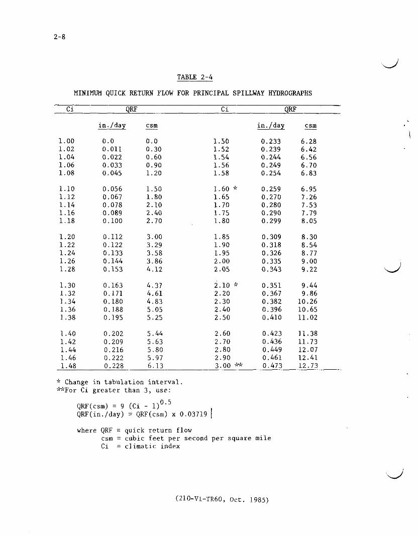
( ( (
0
rt
LEGEND
0 1 - 1-Day Volume Runoff
010- 10-Day Volume Runoff
FIGURE 2-1 (B)
RATIOS OF VOLUMES OF RUNOFF (Q 11Q
10)
PRINCIPAL SPILLWAY HYDROGRAPH
JANUARY 1971 REV APRIL 1976
~
shybullOO ~middotmiddot cbull I I deg
IF~ R lt bull
middot~10
~
I Ngt-gt0I
Hlt I I -middot --~~---CUI V-lf-IJ-H
deg~
0
2
R i
rt I3 4
gt-gt
degln ~
Note For Wisconsin Michigan and eastern I
Iowa use csrn values in circles
FIGURE 2middot1 (C) QUICK RETURN FLOW (csm)
PRINCIPAL SPILLWAY HYDROGRAPH
JANUARY 1971 REV APRIL 1976
(_ ( (
( ( (
115deg r
---------~
~
N 0 I
ltl ----- --- H I
H ~ ashy0 I 40deg-_
0 ()
rt
00
~
-------middot-middot40
LEGEND
JltUgtj Pr1mar1ly snowmelt produced floods
CJ Primarily rain produced floods
[=J Deep snowpack areas
FIGURE 2-2 (A)50-YEAR 10-DAY RUNOFF-Use 85 of map value
25middotYEAR IO-DAY RUNOFF-Use 70 of map value 100-YEAR 10-DAY RUNOFF (INCHES)
PRINCIPAL SPILLWAY HYDROGRAPH SNOWMELT PRODUCING FLOOD AREAS ~
January 1971 Rev Apri I 1976 w
I
0(lrt
_ --1()LEGEND
[j Primarily snowmelt produced floods
LJ Primarily rain produced floods
C=J Deep snowpack areas
Q1 - I-Day Volume RunoffQ10 - 10-0ay Volume Runoff FIGURE 2-2 (B)
RATIOS OF VOLUMES OF RUNOFF (Q 1Q10)JANUARY 1971 REV APRIL 1976 PRINCIPAL SPILLWAY HYDROGRAPH SNOWMELT PRODUCING FLOOD AREAS
( ( (shy
t
bull middotf middotmiddot -~
~
N Use Maps in 0 I lt H I
NOAA Atlas 2 (1973-shyfor the middot
1 1
L v -1
ti[amp 6
lt
deg 0 D
0
rt
(Xgt gt
- ~
II I
0 I bull jTechntc~I- cpoundJ -11middot
ulwa~er 43 -uf)_r111962) 1 I -i~ ~ -f---
~ --middot-middot - 11
-shy
middot-~
bullmiddotmiddot
FIGURE 2-3 MINIMUM 100-YEAR PRECIPITATION
Technical Paper 42 6-HOUR 10-SOUARE MILES (inches) USWB (1961
Technical Paper 47 USWB ( 1963)
APRIL 1976 bullmiddot
middot1middot~
~-
~~-t--
-----shylt
~middotimiddot_ middot
c~ )I-middot_ 1)-~I
8 i
bull1f
EMERGENCY SPILLWAY AND FREEBOARD HYDROGRAPHS ---shy~-- - --shy
~~ ~ ~i~~ cbullbull1BOibull~ middot~
~ U1
-- __L I ___ -~-~- -- -~----middot--
SOURCE HYDROMETEOROGICAL REPORT 5 I CAllbullSbullason PMP - I 978)
middot
_1~ middotmiddot
middotmiddotmiddot~~~~middotmiddot-- _-_r---~lt-gt _ -~ ~~_4--7 l 1 + 1J )lt 4e -i--
Z2 f - -middotr gt dmiddotti~~ft_ ~ - shyI
- __ ~ Ji ~
N middotbull SEE FIClUR~ fL~ bull0I
IJlO~ftRE~q of= APPJicABLlIYlt1 bull bull Olt NWSREFltf~fNdES H - i --r -I fI f i _Mk f- iH +~i_middot~ t bull I0deg ~ I ri
rmiddotmiddot f n0 --J t
H bull I I
-J )I iI
cc Lrj
Vgt ~
I
~
Lmiddot-ief
II NOTE It basin areaI - is greaJer than I 0middot ~-4~I
squara_ miles aeeHydrctmet Reports 5 Iamp 52
-_ Stippled ares are regions
FIGURE 2-4 0 where detailed terrain K effects have not beenPROBABLE MAXIMUM PRECIPITATION ~ evaua ted8-HOUR 10-SQUARE MILES (lnchee) ~EMERGENCY SPILL WAY
AND FREEBOABDliYDROGRAPHS32 4-
Aug I 985
( ( c
( ( (
middot1cent pi - _ smiddot efer nmiddotcmiddote -_fbifmiddot __ _ middotz~K ALAKAmiddotmiddotmiddot~~ c-Tec~~i~ per 4middot1 USWB Cl~~middot _ -~~dlpmet gtoglcaReport 54 (I 9~~ middot
1 1
[ HAWAlti~tJNDSlOo~dfmbulli~or~loglcal Rep~rt 39 ( 1963 FIGURE 2-5
~t_PJJ~Rro=RICO -middot~T~ch~cal Rp~rt42 USWB CI t6 PROBABLE MAXIMUM PRECIPITATIONI) and -middotmiddot- -lt-~r -
ivlRGIN ISLANDS f(bull middot middot NWS REFERENCESJUDY REGIONS N I i t~
JI-bull~~i ~~ ~h~-S f middotgt-
I ~~ ~1~J Ii 1 Aug I 9lf5 ~ ~- -_~-middot--~-~- 1 ~-m~___z__~- 1b~--~
N
_I
10 I I 11 I I I 10 ltXgt
~09 1- - 1 TPACIFIC C0iSTA1 CL~AT+- ~ I - ~ t _HUMID 4ND SU 09
a-_z-
OB -------- ---- -f -1 - BHUM10 CLIM4Tf -
~
_ --+ I 4~ + -= I--
_ I D Atvo ~E 07 08
St1i114 -_1 _ - ---- _J__J-- ~-i-i- I--- --- li10 Cl -_0 +-shy~ 06 ~ 11fq f-
lI - ~+- t-r- Pgt
Ir----+-- -- ---- =gt 6 0
c c t+050 15 x20 25 30 35 40 45 50 60 70 BO 90 100DRAINAGE AREA IN SQUARE MILES
0
I~u 0
~ I
_ A) AREAL PRECIPITATION ADJUSTMENTS FOR gt-z gtshy
Z
00DRAINAGE AREAS 10 to 100 SQUARE MILES J ~a ~
H ~~I ~rl
lt~04~ zshylti i0 0i== 00
~~ 00c c
llt o
deg 0 I00 ~~
~ gt-gtshy zz0
0
~
0 2 3 4 5 6~~ TIME IN HOURSzzlti lti (C) SIX HOUR DESIGN STORM DISTRIBUTION0~
FIGURE 2-6 12 18 EMERGENCY SPILLWAY AND FREEBOARD
TIME IN HOURS VOLUME ADJUSTMENTS AND STORM DISTRIBUTION(B) RELATIVE INCREASE IN RAINFALL AMOUNT
FOR AREAS WHERE NWS REFERENCES DO NOTFOR STORM DURATIONS OVER SIX HOURS CONTAIN AN APPLICABLE PROCEDUREAug 1981
(_ ( (
3-1
SEDIMENTATION
Reservoirs used to store or retard water from surface runoff will trap and store a large portion of the sediment in the runoff water Thereshyfore allocate storage capacity for the calculated sediment accumulation during the design life of the reservoir Criteria and general procedures needed to determine the volume required for sediment accumulation and its allocation in the reservoir are contained in NEH-3 Sedimentation and TR 12 The latter also includes procedures for determining
1 The sediment yield for present conditions and for the future after planned land treatment and other measures are applied in the drainage area of the dam
2 The trap efficiency of the reservoir
3 The distribution and types of sediment expected to accumulate
4 The proportion of the sediment that will be continously submerged vs that aerated and
5 The densities to which the sediment will become compacted
__ If the amount of sediment accumulation calculated exceeds two watershed inches in 50 years for the uncontrolled drainage area of the darn reevaluate the entire watershed to determine if more economical methods of reducing sediment yield or trapping sediment may be feasible and applicable
(210-Vl-TR60 Oct 1985)
4-1
GEOLOGIC INVESTIGATIONS
The intensity and detail of geologic site investigations are to be consistent with the class of dam complexity of site geology and the data needed for
design General requirements procedures and criteria are set forth in 210-V Part 531 and NEH-8
Geologic conditions that require special consideration beyond the minimum investigations spelled out in the above reference are
1 Seismic Assessment -- Dams in zones 3 and 4 Alaska Puerto Rico and the Virgin Islands and high hazard [class(c)] dams in zone 2 (see figure 4-1) require special investigations to determine liquefaction potential of noncohesive strata including very thin layers and the presence at the site of any faults active in Holocene time As part of this investigation a map is to be prepa-red showing the location and intens i tr of magnitude of all intensity V or magnitude 4 or greater earthquakes of record and any historically active faults within a 100 kilometer radius of the site (Obtain earthquake information for this map in printout form from the Environmental Data Service attention D62 NOAA Boulder Colorado 80302 Telephone FTS 323-6472 Commercial (303) 499-1000 ext 6472) The report should also summarize other possible earthquake hazards such as ground compaction landslides excessive shaking of unconsolidated soils seiches and in coastal areas tsunamis
2 Subsidence -- Investigate the potential for surface subsidence due to past or future solid liquid (including ground water) or gaseous mineral extraction Consult the state geological andor evaluation National Engineering Manual 210-V Part 531 Subpart D sets forth criteria for these evaluations
Evaluate the impact of the preemption of mineral deposits including sand and gravel by dams and reservoirs
In arid and semiarid areas and in eolean deposits determine the potential of moisture deficient soil materials to collapse upon saturation or wetting If the potential exists make extensive and intensive site investigations to provide quantitative information for design and construction
3 Emergency Spillways -- Large dams with emergency spillways in soft rock or cemented soil materials that cannot be classified as soil as defined Jn TR 52 nor as rock as generally defined for engineering purposes and spillways in rocks with extraordinary defects require a special individu1l evaluation
(210-VI-TR60 Oct 1985)
4-2
4 Mass Movements -- Evaluate landslides and landslide potential at dam and reservoir sites especially those in shales and where unfavorable dipshyslope or other adverse rock attitudes occur Summarize the history of mass movement in the project area Emergency spillway cuts and reservoir effects must be given careful consideration
5 Karstic areas -- Limestone and gypsum in reservoirs and at damsites require special investigational methods and careful evaluation of subsidence leakage hazards and construction costs Multipurpose structures in these areas are especially critical
6 Multipurpose Dams -- Investigate the ground water regime and hydraulic characteristics of the entire reservoir area of water storage dams and evaluate for leakage Use the water budgets to determine the need for reservoir sealing
7 Other -- Special studies and evaluations may be necessary where such things as compaction shales some types of siliceous calcareous or pyritic shales rebound joints dispersed soils or artesian waters occur at a site
(210-VI-TR60 Oct 1985)
( (
0 I lt I
rel ll
0 0 () rt
00 U1 deg
Minimum Seismic Coefficients
Zone Coefficients-0shy
1 005 2 010
3amp4 Base on Seismic Assessment
0 Q
SEISMIC ZONE MAP of
CONTIGUOUS STATES f w
0
Q
l
Adapted From TM 5-809-10 NAVFAC P-355 AFM 88-3 Chapter 13 April 1973
f KAUAI
~ 8LIHUE
OAHU ocE~N NllHAU
~ HONOLULU
MOLOKAI I----
KAUN~
LANAI Cl~~ ~
N ~
0 P~c1f c bullLANAI I
lt1 H KAHOOLAWE I gt-l_ 10 0 10 20 30 40
deg STATUTE MILES 0 0 (l rt
bullHILO ~ MinimlDil Seismic Coeficients 00 Ln ~
gt-bull OQ
Zone Coefficients
ro 0 0
1 005 I
gt- 2 010
romiddot ro
3amp4 Base on Seismic Assessment
rt
SEISMIC ZONE MAP 0
Hawaii
Adapted From TM 5-809-10 NAVFAC 0-355 AFM 88-3 Chapter 13 April 1973
( ( (
5-1
EARTH EMBAlKMENTS AND FOUNDATIONS
Earth embankments constructed of soil and rock are the principal means of impounding water The earth embankment and its foundation are to withstand the anticipated loads without movements leading to failure Measures are to be provided for adequate seepage control
Height
The design height of an earth embankment is to be sufficient to prevent overshytopping during passage of either the (1) freeboard hydrograph or (2) the emergency spillway hydrograph plus the freeboard required for frost condishytions or wave action whichever is larger The design height must also meet the requirements for minimum emergency spillway depth The design height of the dam is to be increased by the amount needed to compensate for settlement
Top Width
The minimum top width of embankment is shown in Table 5-1
Table 5-1
Minimum Top Width of Embankment
Total Height of Embankment
(feet) (H) All
Dams
Top Width Single Purpose
Floodwater Retarding
(feet) Multipurpose
or other Purposes
14 or less 8 15 - 19 10 NA NA 20 - 24 12 25 - 34 14
H + 35 35 - 95 NA 14 5 Over 95 NA 16 26
The width may need to be greater than the above minimums to (1) meet state and local standards (2) accommodate embankment zoning (3) provide roadway access and traffic safety and (4) provide structural stability An increase in top width is a major design feature in preventing breaching after embankshyment slumping caused by earthquake ground motion
When the embankment top is used as a public roadway the minimum width is to be 16 feet for one-way and 26 feet for two-way traffic Guardrailsmiddot or other safety measures are to be used and are to meet the requirementsof the responsible road authority
(210-VI-TR60 Oct 1985)
5-2 Embankment Slope Stability
Analyze the stability of embankment slopes using generally accepted methods based on sound engineering principles Document all analyses or considerations in appropriate design reports and files Design the embankment cross section to provide adequate factors of safety against sliding sloughing or rotation in the embankment and foundation Use the appropriate degree of conservatism in the analysis that is consistent with the adequacy of the site investigation and soil testing program and with the complexity of the site and consequences of failure Minimum factors of safety are listed in table 5-2
Evaluate the effect of seismicity on each site Include the determination of whether the site is in a seismically active area its proximity to active faults and the predicted site ground motion intensity Use the minimum seismic coefficient shown in Figure 4-1 in the slope stability analysis when no special seismic assessment is made
Analyze embankment slope stability for the conditions and periods during the design life of the structure that are most critical or severe Use conditions in the analysis based on possible critical water levels and loadings of the embankment and foundation Consider and document the following conditions or periods (1) end of construction (2) steady seepage (3) rapid drawdown and (4) during seismic loading Use the shear strength parameters and minimum factors of safety indicated in Table 5-2 for each case The nomenclature for the various shear strength tests is listed in Table 5-3
Calculate the factor of safety based on the ratio of the shear strength available to the shear strength mobilized
Clearly document the conditions not analyzed correlated shear strength parameters or correlation to field performance
Consider the following additional details in conjunction with Table 5-2
I End of Construction Make a detailed analysis of this case when significant pore pressure development during construction is expected in either the embankment or foundation soils Embankment soils are to be tested at the highest likely placement water content and foundation soils are to be tested at saturation Select shear strength parameters according to Table 5-2
II Rapid Drawdown Analyze the stability of the upstream embankment slope for the condition created by a rapid drawdown of the water level in the reservoir Use a phreatic surface in the embankment developed from the emergency spillway crest with the water level in the reservoir drawn down to the crest of the lowest gated or ungated outlet Failure surfaces are to be confined to the embankment only if foundation soils are free-draining Use infinite slope stability equation appropriate to drainage conditions of the embankment soils whenever the c or c value being used in the analysis is zero In addition to the infinite slope analysis circular arch or sliding wedge analyses may be needed to check stability where failure surfaces could extend into weaker core
(210-VI-TR60 Oct 1985)
5-3
zones or into the foundation Select shear strength parameters according to Table 5-2
III Steady Seepage Without Seismic Forces Analyze the downstream slope for the condition of steady seepage developed from the water surface at the principal spillway crest In the analysis saturated soils will be subjected to uplift forces simulated by a piezometric surface developed from the emergency spillway crest Phreatic surfaces and piezometric surfaces may be developed using flow nets or Casagrande procedures Select shear strength parameters according to Table 5-2
IV Steady Seepage With Seismic Forces Analyze the downstream slope for the condition of steady seepage developed from the water surface at the principal spillway crest with a horizontal force equal to the effective weight multiplied by the earthquake coefficient applied at the failure surface (pseudo-static analysis) Uplift forces due to the reservoir at the emergency spillway level need not be included because of the very remote potential for the simultaneous occurrence of an earthquake and an emergency spillway storm event A two or three dimensional computer analysis may be used instead of a pseudo-static analysis if desired Select shear strength parameters according to Table 5-2
V Steady Seepage With and Without Seismic Forces Determine the results of the analysis using either the total stress or effective stress shear strength parameters that are the most limiting (those resulting in the lowest factor of safety) Analyses are to include the use of various combinations of total stress parameters in certain zones and effective stress parameters in other zones The combinations that may be most limiting can usually be narrowed to one or two by inspection and judgement without analyzing all possible combinations
VI Additional Guidance
A Effective stress shear strength parameters are generally the most limiting for any free draining soil
B Total stress shear strength parameters are generally most limiting for non-free draining foundation soils that exhibit positive pore pressure buildup during undrained shear testing
C Effective stress shear strength parameters are generally most limiting for non-free draining foundation soils that exhibit negative pore pressure buildup during undrained shear testing
D Analyses will generally have to be made using both total and effective stress shear parameters to determine the most limiting for non-free draining embankment soils that exhibit either small negative or positive pore pressures during undrained shear testing
E Effective stress shear strength parameters are generally most limiting for non-free draining embankment soils that exhibit highly negative pore pressures during undrained shear testing
F Total stress shear strength parameters are generally most limiting for non-free draining embankment soils that exhibit highly positive pore pressures during undrained shear testing
(210-VI-TR60 Oct 1985)
TABLE 5-2 SLOPE STABILITY CRITERIA FOR DAMS
Design Condition Primary Assumption Remarks Minimum Factor ___o_f__s a tot v
I bull End of construcshytion (upstream or downstream slope)
Significant construction pore pressures expected in cert a In zones of the embank~
ment or layers In the foundation
1
2
Embankment conshyta In 1ng Impershyvious sol Is at water contents aqua I to or greatagtr than optimum water content andor Saturated Impershyvious foundation strata too thick to tully consolishydate duriog construction
uu I 4 ( 13 ls acceptshyable for embankshyments on strong foundations Ie the fal lure surshyf ace Is I ocated entirely In the embankment)
Peryen1ous embankment zones andor foundashyt I on strata
CiT or CD
I I Rapid drawdown (upstream slope)
Drawdown sp 111 way
from the crest to
emergency the crest
Fa 11 ure surface can be confined to the
Use alternative I or 2 below -
1 2
of the ungated
lowest gated outlet
or embankment or extend Into the foundation 1 Lowest shear If low permeability sol ls are Involved
strength from composite enveshylope of CU and CiT
or
2 Most IJr_ltlng3 of CU or CU or a combination ot both
(For alternative 2 only use shear strength tat lure crterle ot 01+03 maximum for dilative soils tested with backpressure saturation techniques This Is to avoid rel lance on high coh~shyslon developed by negative pore presshysure as a result of water tension)- --~-------------------middotmiddot-middot--------------- ---------------middot------ ___________________________
NOTE See bottom of next sheet tor explanatfon of footnotes
(210-VI-TR60 Oct 1985)
(_
( ( (
TABLE 5-2 (Contd) SLOPE STABILITY CRITERIA FOR DAMS
Design Condition Primary Assumption Remarks Shear strength Minimum Factor To Be Used 12 of Safety-
I I I bull Steady seepage I bull Water surf ace at the Fal lure surface con- nr or CD 1 bull 5 without seismic principal spillway f In ed to the embank-forces (down- crest and phreatic ment on I y stream s 1ope) surface f u I I y developed
through the embankment
2 Plezometrlc surface for Fal lure surface Most I Jmitlng3 of cu 1 bull 5 estimating up I If t In extends Into the or m or a comb Ina-saturated so I I zones Is foundation tlon of both determined with water level at the emergency spillway crest
IV Steady seepage 1 bull Water surface at The Fal lure plane may be Most I imlting3 ot CU 1 bull 1 with seismic crest of the principal cont I ned to the or C1T or a comblnashyforces Cd own- spi 1 lway and phreatlc embankment or may tlon of both stream slope) surface f u I I y developed extend Into the
through the emban-kment foundation
1 Use CU or CD shear strength tor pervlous sol I zones within the foundation or embankment
2 Use Infinite slope stabl I lty analysis whenever the C or C Intercept strength Is zero tor so I Is that are -tested to simulate low cont In Ing pressures This situation exists for tal lure surfaces located near the embankment surface Minimum factor ot safety for the Infinite slope stability analysis Is 11
3 Most llmltlng Is the combination resulting In the lowest factor ot safety
n I
n
(210-VI-TR60 Oct 1985)
5-6
TABLE 5-3
NOMENCLATURE OF SHEAR STRENGTH TESTS
Test Parameters scs Common Condition Obtained Descriltion Abbreviation
Unconsolidated Total Y uu Q Undrained Stress
Consolidated Total Y cu R Undrained Stress
Consolidated Effective _I cu R Undrained with Stress pore pressures measured
Consolidated Effective Y CD ii s Drained Stress
ll Total stress shear strength parameters are determined when no drainage is allowed during the test using the external stresses imposed on the soil specimen When used in a total stress analysis the assumption made is that the pore pressure developed (negative or positive) during loading is the same in the laboratory as it is in the field
_I Effective stress parameters are determined from undrained tests by using the intergranular stresses (total stress minus the pore water stress) on the soil particles When used in an effective stress analysis any effects of pore pressure development (positive or negative) resulting from load application must be accounted for in the analysis
ii The CD tests allow drainage during load application If the load is applied slow enough complete drainage occurs so that no pore pressure develops and the shear strength parameters obtained should be the same as CU parameters
(210-VI TR60 Oct 1985)
5-7
Seepage
To the extent needed an analysis is to be made of anticipated seepage rates and pressures through the embankment foundation abutments and reservoir perimeter (when storage is desired) Controls and treatment should be adequate to (1) accomplish the intended reservoir function (2) provide a safely operating structure and (3) prevent damage to downstream property
Zoning
Embankment zoning can be used when needed to (1) obtain a stable structure with the most economical use of available materials (2) control seepage in a safe manner or (3) reduce to a minimum the uncertainties of material strengths and resultant stability
Embankment zones should be a minimum of 10 feet wide except for filters and drains with specified and controlled gradation Drains and filters should meet the requirements contained in Soil Mechanics Notes
Soil materials which exhibit significant shrinkage swell or dispersion are to be used only with extreme care If possible they should not be used for embankment construction When there is no economical alternative to their use they are to be (1) treated to improve their performance (2) placed in zones where effects will not be detrimental or (3) protected by use of filters and drains or self-healing transition zones
Surface Protection
Embankment surfaces are to be protected against surface erosion Protection may be vegetative gravel rock riprap soil cement structural or similar treatment of durable quality and proven satisfactory performance
Vegetative Protection Vegetative protection may be used on surfaces where the following conditions can be met (1) inundation of the surfaces is of such frequency that vegetative growth will not be inhibited (2) vigorous growth can be sustained under average climatic conditions by normal maintenance without irrigation and (3) stable protection can be designed according to the procedures in TR-56
Structural Protection Protection against wave erosion by riprap or other structural measures is to be provided as follows (1) for dams where vegetation will not provide effective control (2) for multiple purpose dams and (3) for dams with fluctuating normal water levels
Protection is to extend from the lowest drawdown elevation that presents an erosion hazard to a few feet above the crest of the lowest ungated spillway The upper limit is to be based on an analysis of anticipated wave height and run up
Quality of riprap and other structural protection is to be consistent with the anticipated life of the dam and designed to be structurally stable
(210-VI TR60 Oct 1985)
6-1
PRINCIPAL SPILLWAYS
The structural design and detailing of principal spillways are to conform to the recommendations of National Engineering Handbook Section 6 Structural Design and SCS standard drawings All component parts of principal spillways except easily replaceable parts such as gates and trash racks are to be equally durable
Capacity of Principal Spillway
The required capacity of the principal spillway depends on (1) purpose of the dam (2) the amount of storage provided by the retarding pool (3) the kind of emergency spillway (4) stream channel capacity and stability downstream (5) potential damage from prolonged storage in the retarding pool (6) potential damage downstream from prolonged high outflow rates (7) possibility of substantial runoff from two or more storms in the time required to empty the retarding pool (8) limitations imposed by water rights or other legal requirements (9) environmental concerns (10) planned or potential alterations of the channel downstream and (11) the necessity to pass base and flood flows during construction
The principal spillway may be single-stage having an ungated inlet at only one elevation or multiple-stage having inlets at two or more elevations In the case of multiple-stage spillways the lower stage or stages usually perform the primary flood control function and the high stage has the capacity needed to prevent the emergency spillway from functioning more frequently than permissible
The principal spillway capacity should be adequate to empty the retarding pool in 10 days or less This requirement is considered to be met if 15 percent or less of the maximum volume of retarding storage remains after 10 days Where low release rates are required to meet the objectives of the project a longer period than 10 days may be needed For these situations additional storage is required to minimize the opportunity for increased frequency of emergency spillway flow due to recurring storms
Compute the 10-day drawdown from the time the maximum water surface elevation is attained during the passage of the principal spillway hydrograph The entire design inflow hydrograph including quick return flow upstream releases and outflow are to be considered in determining the evacuation time of the retarding storage The inflow from storm runoff must be considered for the entire evacuation time
For dams where more than 15 percent of the retarding storage volume remains after 10 days the elevation of the crest of the emergency spillway will be raised The raised crest elevation is determined by adding the remaining retarding storage volume to the initial retarding storage volume
(210-Vl-TR60 Oct 1985)
6-2
Elevation of Principal Spillways
Single Purpose Floodwater Retarding Dams The crest of the principal spillway or of the low stage inlet of a two-stage principal spillway is to be set at the sediment pool elevation For dry dams the elevation of the principal spillway inlet is to be placed as described above and provisions are to be made to drain the reservoir in a reasonable time and thus satisfy the functional or legal requirements of the dam
Other Dams When conservation storage is to be provided the elevation of the crest of the lowest ungated inlet of the principal spillway is to be determined by the volume area or depth of water required for the planned purpose or purposes and the required sediment storage The lowest crest may be the crest of the low-stage inlet single-stage inlet or an open spillway
Routing of Principal Spillway Hydrographs
Reservoir flood routing used to proportion dams and associated spillways is to be based on the assumption that all sedimentation expected in the reservoir during its design life has occurred The reservoir stage-storage curve used for routing should reflect the anticipated accumulation of sediment The initial reservoir stage for principal spillway hydrograph routing is to be at the crest of the lowest ungated inlet or (if not subtracted from the stage-storage curve) the anticipated elevation of the sediment storage whichever is higher except as provided in items 1 2 and 3
1 For dams with significant base flow principal spillway hydrograph routings must start not lower than the elevation of the water surface associated with the base flow Significant base flow is average annual or seasonal flow that would produce at least 05 feet of head over the lowest principal spillway inlet immediately prior to a flood or occupy more than 10 percent of the floodwater storage capacity
2 For dams with joint use storage capacity when one of the uses is floodwater detention routing of the principal spillway hydrograph may begin at the lowest anticipated elevation of the joint use pool in accordance with the operation plan
3 Single purpose class (a) irrigation dams with gated outlets and earth or vegetated emergency spillways which are located on ephemeral streams in areas where the average annual precipitation is less than 25 inches may be considered to have discharged up to 70 percent of the storage exculsive of sediment storage in determining the elevation to start routing
Design of Principal Spillways
Hydraulics The principal spillway is to be designed to carry the planned flow for expected head and tailwater conditions TR-29 Design Note No 8 NEH-5 the Engneering Field Manual for Conservation Practices and other appropriate references are to be used for hydraulic design
(210-VI-TR60 Oct 1985)
6-3
Risers Risers for drop inlet spillways are to be designed to maintain the reservoir pool level at or near the inlet crest elevation during low flow periods to establish full pipe flow at as low a head over the crest as practical and to operate without excessive surging noise vibration or vortex action at any reservoir stage Ibis requires the riser to have a larger cross sectional area than the conduit Standard risers have an inside width equal to the width (diameter) D of the conduit and an inside length equal to three times the width (diameter) of the conduit (D x 3D cross section)
Risers are to be designed to exclude trash too large to pass freely through the spillways including the outlet structure and to facili shytate the passage of smaller trash Standard D x 3D risers tend to line up longer pieces of trash and facilitate their passage into and through the conduit Covered risers with standard skirted or baffle inlets should be used in most cases because they are most effective in excluding trash without becoming clogged Skirted inlets having a cover with skirts extending below the weir crest elevation are applicable where backfill or settlement levels are to be at least two times the conduit width (diameter) below the crest Baffle inlets are applicable for risers that are to be backfilled to the crest eleshyvation or where sediment is expected to build up to the crest elevation
Risers are to be designed structurally to withstand all water earth ice and earthquake loads to which they may be subjected Articulation is to be provided to allow movement of the riser with respect to the conduit
Risers with low-stage inlets at or near the bottom are to be provided with concrete aprons to prevent erosion of soil and undermining of the riser footing by high velocity flow approaching the inlet
Standard risers are to be used where applicable for class (a) dams with an effective height of more than 35 feet and for all class (b) and class (c) dams Prefabricated pipe risers are permissible where hydraulically and structurally adequate for class (a) dams not more than 35 feet in effective height The riser pipe is to be of the same material as the conduit and at least one standard pipe size larger then the conduit pipe
Special riser designs are required for spillways having maximum conduit velocities more then 30 feet per second and for spillways having conduits larger then 48 inches in width (diameter) Generally these should be similar to standard risers but a special elbow and transition is required at the junction of the riser and conduit and special design of the inlet may be necessary Hydraulic model testing should be considered if the maximum total head on the spillway is more than 75 feet or the conduit velocity exceeds 50 feet per second
(210-Vl-TR60 Oct 1985)
6-4
Conduit The conduit should be straight in alignment when viewed in plan Changes from straight alignment if required are to be accomplished by watertight angle changes at joints or by special elbows having a radius equal to or greater than the diameter or width of the conduit Thrust blocks of adequate strength are to be provided if special pipe elbows are used They are to be designed to distribute the thrust due to change in direcshytion for the maximum possible discharge Drop inlet conduits are to be installed with enough slope to insure free drainage to the outlet of all parts of the conduit (including camber) at the time of construction and under the maximum anticipated settlement
All condbull1its under earth embankments are to support the external loads with an adequate factor of safety They are to withstand the internal hydraulic pressures without leakage under full external load and settlement They are to convey water at the design velocity without damage to the interior surface of the conduit
Principal spillway conduits under earth dams may be designed to support fill heights greater than the original constructed height if there is a reasonable possibility that the embankment height may be raised later to incorporate additional storage for some approved beneficial use
Rigid principal spillway conduits are to be designed as positive projecting conduits in accordance with the principles and procedures given in TR-5
Principal spillway conduits are to be of reinforced concrete pressure pipe or cast-in-place reinforced concrete unless corrugated steel or welded steel pipe is used in accordance with subsection 2 which follows
Cast-in-place rectangular reinforced concrete conduits are to be designed in accordance with principles and procedures in TR-42 TR-45 or other appropriate design aids
For Reinforced Concrete Water Pipe - - Steel Cylinder Type Prestressed ~eting specification AWWA C301 the 3-edge bearing strength at the first 0001-inch crack is to be used with a safety factor of at least one
For Reinforced Concrete Water Pipe - - Steel Cylinder Type Not Prestressed meeting specification AWWA C300 for Reinforced Concrete Water Pipe -Noncylinder Type Not Prestressed meeting specification AWWA C302 and for other types of reinforced concrete pipe the 3-edge bearing strength at the first 001-inch crack is to be used with a safety factor of at least 133
Elliptical or other systems of reinforcement requiring special orientation of pipe sections are not permitted in spillway conduits
Reinforced concrete pipe is to be designed to support at least 12 feet of earth fill above the pipe at all points along the conduit
(210-VI-TR60 Oct 1985)
6-5
1 Reinforced Concrete Pipe - (A) Minimum Inside Diameters on Yielding Foundations Class (a) dams The minimum diameter of the principal spillway conduit is to be 30 inches unless a joint extension safety margin of at least 15 inches is used in which case the minimum diashymeter is to be 18 inches for maximum fill heights up to 50 feet at the centerline of the dam and 24 inches for greater fill heights
Class (b) dams The minimum diameter of the principal spillway conduit is to be 30 inches unless a joint extension safety margin of 15 inches is used in which case the minimum diameter is to be 24 inches
Class c) dams The minimum diameter of the principal spillway conduit is to be 30 inches
(B) Minimum Inside Diameters on Non-Yielding Foundations The minimum diameter of the principal spillway conduit for class (a) dams is to be 18 inches for heights up to 50 feet at the centerline of the dam and 24 inches for heights greater than 50 feet and 24 inches for all class (b) and (c) dams The conduit and cradle or bedding are to rest directly on firm bedrock thick enough so that there is essenti shyally no foundation consolidation under the conduit Under these conditions the cradle or bedding under the conduit need not be articulated
2 Corrugated Steel Pipe or Welded Steel Pipe - Principal spillways of corrugated steel or welded steel pipe may be used for single purpose class (a) dams with the product of storage times effective height of dam less than 10000 While installation costs of steel pipes may be less concrete may compare favorably with steel when replacement costs and associated problems are considered
In each case the following limitations apply
a Diameter of pipe not less than 18 inches b Height of fill over the pipe not more than 25 feet c Provision for replacement if the materials will not
last for the design life of the structure d Pipe structurally strong enough to withstand outside
loads and hydraulic pressure e Pipe Watertight
Corrugated steel pipe is to be close riveted asbestos treated and asphalt coated with watertight connecting bands The minimum gage is to be that designed for 35 feet of fill over the pipe
Welded steel pipe conduits are to be structurally designed as rigid pipe A joint extension safety margin of 15 inches is to be provided for conduits on yielding foundation Welded steel pipe is to be protected by a Class A exterior coating as defined in the specifications guide for steel irrigation pipeline Engineering Practice Standard 432-F (NEH-2) or by an exterior coating of coal tar-epoxy paint conforming to Paint System I Construction Specification 82 (NEH 20)
(210-VI-TR60 Oct 1985)
Joints between lengths of corrugated steel or welded steel pipe other than welded joints are to be electrically bridged on the outside of the pipe with insulated copper wire 6 AWG or larger securely attached to the uncoated pipe metal at both sides of the joint This requirement applies whether or not the cathodic protection is completed by the installation of anodes etc The wire s hould have a tough waterproof insulation designed for direct burial with a rating of at least 600 volts Bare wire and exposed pipe metal at the points of connection are to be thoroughly coated with a coating equivalent to the original pipe coating to prevent the entry of moisture
Soil investigations for resistivity and pH of the subgrade and backfill materials to be adjacent to the condui t are to be made The resis t ivity measurements are to be made on saturat ed samples
Cathodic protection is to be provided for welded steel pipe conduits according to the criteria in Engineering Practice Standard 432-F (NEH-2) and 432-F specifications guide
Cathodic protection meet i ng the above r equirements i s to be provided for corrugated steel pipe in soil whose resistivity in a saturated condition is less than 4000 ohms-cm or whose pH is lower than 5 0
If cathodic protection is not required according to the above criteria and anodes are not installed during construction of the dam pipe- to-soil potentials are to be measured within the first 2 years after construction or after the water level has stabilized and when t he soil around the conduit is estimated to be at its normal post-construction moisture content Cathodic protection is to be installed at this time if such measurements indicate it is needed
Joints Conduit joints are to be des i gned and constructed to remain watertight under maximtun anticipated hydrostatic head and maximum probab l e joint opening as computed from Standard Drawing ES- 146 and r e l ated procedures of TR 18 including the effects of joint rotation and the required margin of safety The required joint extensibility is equal to the unit horizontal strain in the earth adjacent to the conduit multipl i ed by the length (in inches) of the section of conduit between joints plus the extension (in inches) due to calculated joint rotation plus a margin of safety
A margin of safety of not less than 05 inch shall be used The required joint extensibility plus the maximum permissible joint gap equals the required joint length The required joint extensibility depends on the maximum
potential foundation consol i dation under the spillway barrel For class (b) and (c) dams the consolidation is to be estimated f r om adequate founshydation borings and samples soil mechanics l aboratory tes ts and engineering analysis For class (a) dams where undis turbed foundation samples are not taken for other purposes approximate procedures based on soil classification and experience may be used for estimating foundation consolidation
(210-VI-TR60 Oct 1985)
6-7
Only joints incorporating a round rubber gasket set in a positive groovewhich will prevent its displacement from either internal or external pressure under the required joint extensibility are to be used on precast concrete pipe conduits Concrete pipe must have steel joint rings providing rubber to steel contact in the joint
Articulation of the conduit (freedom for required rotation) is to be provided at each joint in the conduit at the junction of the conduit with the riser and any outlet structure Concrete bedding for pipe conduits need not be articulated Cradles are to be articulated if on yielding foundations Welded steel pipe conduits need not be articulated if the pipe and bedding rest directly on firm bedrock
Piping and Seepage Control - Use a filter and drainage diaphragm around any structure that extends through the embankment to the downstream slopeDesign the diaphragm with single or multizones to meet the requirements of Soil Mechanics Note No 1
Locate the diaphragm aligned approximately parallel to the centerline of the dam or approximately perpendicular to the direction of seepage flow Extend the diaphragm horizontally and vertically into the adjacentembankment and foundation to intercept potential cracks poorly compactedsoil zones or other discontinuities associated with the structure or its installation
Design the diaphragms to extend the following minimum distances from the surface of rigid conduits
l Horizontally and vertically upward 3 times the outside diameter of circular conduits or the vertical dimension of rectangular box conduits except that
a the vertical extension need be no higher than the maximum potential reservoir water level and
b the horizontal extension need be no further than 5 feet beyond the sides and slopes of any excavation made to install the conduit
2 Vertically downward
a for conduit settlement ratios (o) of 07 and greater (reference SGS Technical Release No 5) the greater of (l) 2 feet or (2) 1 foot beyond the bottom of the trench excavation made to install the conduit Terminate the diaphragm at the surface of bedrock when it occurs within this distance Additional control of general seepage through an upper zone of weathered bedrock may be needed
b 15 times the outside diameter of circular conduits or the outside vertical dimension of box conduits for conduit settlement ratios (o) less than 07
(210-VI-TR60 Revised Amend 1 Oct 1990)
6-8
Design the diaphragms to extend in all directions a minimum of 2 times the outside diameter from the surface of flexible conduits except that the diaphragm need not extend beyond the limits in la and lb above nor beyond a bedrock surface beneath the conduit
Provide minimum diaphragm thickness of 3 feet and minimum thickness of 1 foot for any zone of a multizone system Use larger thickness when needed for (1) capacity (2) tieing into embankment or foundation drainage systems (3) accommodating construction methods or (4) other reasons
For homogeneous dams locate the diaphragm in the downstream section of the dam such that it is
1 Downstream of the cutoff trench
2 Downstream of the centerline of the dam when no cutoff trench is used and
3 Upstream of a point where the embankment cover (upstream face of the diaphragm to the downstream face of the dam) is at least one-half of the difference in elevation between the top of the diaphragm and the maximum potential reservoir water level
For zoned embankments locate the diaphragm downstream of the core zone andor cutoff trench maintaining the minimum cover as indicated for homogeneous dams When the downstream shell is more pervious than the diaphragm material locate the diaphragm at the downstream face of the core zone
~ Lt is good practiceto tie these diaphragms into the other drainage systems in the embankment or foundation Foundation trench drains andor embankment chimney drains that meet the minimum size and ~ocation limits are sufficient and no separate diaphragm is needed
Design the minimum capacity of outlets for diaphragms not connected to other drains by assuming the coefficient of permeability (k) in the zone upstream of the diaphragm is 100 times the coefficient of permeability in the compacted embankment material Assume this zone has a cross-sectional area equal to the diaphragm area and the seepage path distance equal to that from the embankment upstream toe to the diaphragm This higher permeability simulates a sealed filtet face at the diaphragm with partially filled cracks and openings in the upstream zone
For channels chutes or other open structures seepage and piping control can be accomplished in conjunction with drainage for reduction of uplift and water loads The drain properly designed to filter the base soils is to intercept areas of potential cracking caused by shrinkage differential settlement or heave and frost action These structures
9 US Government Printing Office 1991 - 282-95740388
(210-VI-TR60 Revised Amend 1 Oct 1990)
- ~ -
6-9
usually require the use of footings keywalls and counterforts and drainage is properly located iDBDediately downstream of these features This drainage when properly designed can control pip1ng and provide significant economies due to the effect on soil loads uplift pressures overturning forces and sliding stability
Outlets
The choice of outlet is to be based on a careful consideration of all site and flow conditions that may affect operation and energy dissipation
1 Cantilever outlet and plunge pools may be installed where their use
a Does not create a piping hazard in the foundation of the structure
b Is compatible with other conditions at the site
Plunge pools are to be designed to dissipate the energy and be stable Unless the pool is to be in bedrock or very erosion resistant materials riprap will be necessary to insure stability Design Note 6 entitled Armored Scour Hole for Cantilever Outlet is to be used for design
Cantilever outlets are to be supported on bents or piers and are to extend a minimum of 8 feet beyond the bents or piers The bents are to be located downstream from the intersection of the downstream slope of the earth embankment with the grade line of the channel below the dam They are to extend below the lowest elevation anticipated in the plunge pool The invert of the cantilever outlet is to be at least 1 foot about the tailwater elevation at maximum discharge
2 SAF basins may be used when there is adequate control of tailwater Use TR-54 for structural design and NEH-14 for hydraulic design
3 Impact basins may be used when positive measures are taken to prevent large debris from entering the conduit TR-49 is to be used for hydraulic design
Trash Racks
Trash racks are to be designed to provide positive protection against clogging of the spillway under any operating level The average velocity of flow through a clean trash rack is not to exceed 25 feet per second under the full range of stage and discharge Velocity is to be computed on the basis of the net area of opening through the rack
If a reservoir outlet with a trash rack or a ported concrete riser is used to keep the sediment pool drained the trash rack or riser is to extend above the anticipated sediment elevation at the riser to provide
(210-VI-TR60 Oct 1985)
for full design flow through the outlet during the design life of the dam The velocity through the net area of the trash rack above the maximum sediment elevation must not exceed 2 feet per second when the water surface in the reservoir is 5 feet above the top of the trash rack or riser inlet
Antivortex Device
All closed conduit spillways designed for pressure flow are to have adequate antivortex devices
High Sulfate Areas
Under certain conditions concrete is susceptible to deterioration from sulfate ions especially those derived from sodium and magnesium sulfates In areas where experience or soil tests indicate the potential for problems the following table will be used for design purposes
Sulfate Concentration (parts per million) Hazard Corrective Measures
0 - 150 Low None
150 - 1000 Moderate Use Type II Cement (ASTM C-150) Adjust mix to protect against sulfate action
1000 - 2000 High Use Type V Cement (ASTM C-150) Adjust mix to protect against sulfate action Use soils in contact with concrete surfaces that are low in sulfates
2000 - up Do not use concrete materials unless measures are taken to protect concrete surfaces from sulfates Product manufacturers should be consulted
Sulfate concentration is for soil water at the concrete surface
7-1
EMERGENCY SPILLWAYS _
Emergency spillways are provided to convey excess water through over or around a dam They are usually open channels excavated in natural earth earthfill rock or constructed of reinforced concrete
Closed Type Spillways
An open channel emergency spillway is to be provided for each dam except as provided below
1 Class (a) dams with a product of storage times the effective height of the dam of less than 10000 - A closed conduit principal spillway havshying a conduit with a cross-sectional area of 12 square feet or more an inlet which will not clog an elbow designed to facilitate the passage of trash and large enough to pass the routed freeboard hydrograph is the minimum acceptable design without an open channel emergency spill shyway The minimum capacity will be taken from Figure 7-1
2 Dams with drainage areas of 10 square miles or less (except those covered by item 1) - A closed conduit principal spillway having a conduit with a cross-sectional area of 20 square feet or more an inlet which will not clog an elbow designed to facilitate the passage of trash and large enough to pass the routed f reeboard hydrograph peak discharge without overtopping the dam is the minimum acceptable design without an open channel emergency spillway In no case is the capacity of the spillway provided to be less than that determined from Figure 7-1
3 Dams with drainage areas greater than 10 square miles (except those covered by item 1) - A closed type primary emergency spillway may be used in lieu of an open channel emergency spillway Drop inlet spill shyways with a standard two-way covered top inlet are to have a minimum unobstructed cross-sectional area of each opening of the conduit of 40 square feet All other closed type primary emergency spillways are to have a minimum unobstructed cross-sectional area of each opening of 80 square feet The ratio of width to height in both cases is to be between 075 and 133 The spillways must be large enough to pass the routed freeboard hydrograph peak discharge without overtopping the dam In no case is the capacity of the primary emergency spillway provided to be less than that determined from Figure 7-1
Spillway Requirements
Capacity of Emergency Spillways Emergency spillways are to be proportioned so they will pass the emergency spillway hydrograph at the safe velocity determined for the site They are to have sufficient capacity to pass the freeboard hydrograph with the water surface in the reservoir at or below the elevation of the design top of the dam In no case is the capacity of the emergency spillway to be less than that determined from Figure 7-1 The minimum difference in
(210-Vl-TR60 Oct 1985)
7-2
elevation between the crest of the emergency spillway and the settled top of the dam is three feet
State law may establish minimum capacity or depth greater than those given above
Elevation of the Crest of the Emergency Spillway Table 2-2 Page 2-6 gives the maximum allowable frequency of use of earth and vegetated emergency spillways The minimum retarding storage volume and the associated principal spillway discharge are to be such that (1) the discharge through the emergency spillway will not occur during the routing of the principal spillway hydrograph and (2) the 10-day drawdown requirement is met or the crest elevation of the emergency spillway is raised as noted on page 6-1 Capacity of Principal Spillway
For earth spillways it refers to sites where peak flows of short duration may be expected and where erosion resistant soils and moderate slopes exist When vegetated spillways are used the sites must have these same characteristics and in addition conditions must be such that vigorous vegetation can be maintained without irrigation When conditions are less favorable emergency spillways are to be designed for less frequent use This may be done by (1) raising the crest elevation (2) increasing the capacity of the principal spillway (3) adding a structural primary emergency spillway or (4) a combination of the above
The maintenance required for the emergency spillway will be increased as the frequency and duration of flow increase Good design requires balancing the spillway maintenance cost against the increased cost of modifying the other elements of the dam to reduce the flow frequency
Emergency Spillway Routings The emergency spillway and the f reeboard hydrographs are to be routed through the reservoir starting with the water surface at the elevation of the lowest ungated principal spillway inlet the anticipated elevation of the sediment storage the elevation of the water surface associated with significant base flow or the pool elevation after 10 days of drawdown from the maximum stage attained when routing the principal spillway hydrograph whichever is higher except as provided in items 1 and 2
1 Dams with gated spillways and joint use storage capacity - Emergency spillway and freeboard hydrograph routings are to be started at or above the elevation of the lowest ungated outlet or at the elevation of the water surface associated with the average annual base flow whichever is higher
2 Single purpose class (a) irrigation dams - Emergency spillway and freeboard hydrograph routings are to be started at or above the water surface elevation of the irrigation storage
(210-VI-TR60 Oct 1985)
7-3
Hydraulic Design The relationship between the water surface elevation in the reservoir and the discharge through the emergency spillway is to be evaluated by computing the head losses in the inlet channel upstream of the control section or if a control section is not used by computing the water surface profile through the full length of the spillway Bernoullis equation and Mannings formula are to be used to evaluate friction losses compute water surface profiles and determine velocities Policy on the selection of n11 values is given in the discussion of the various types of emergency spillways
Structural Stability The spillway is to be investigated analyzed designed and constructed adequately to establish and maintain stability during the passage of design flows without blockage or breaching Excavated open cut spillways arr to have cut and fill slopes in earth and rock which are stable against slmiddotding Cut slope stability is to be evaluated for the long term weathered natural moisture condition and for adverse moisture conditions associated with rapid drawdown from the emergency spillway design discharge
Vegetated and Earth Emergency Spillways
Vegetated and earth emergency spillways are open channels and usually consist of an inlet channel a control section and an exit channel Subcritical flow exists in the inlet channel and the flow is usually supercritical in the exit channel
Vegetated emergency spillways are usually trapezoidal in cross-section and are protected from damaging erosion by a grass cover They are adapted to sites where a vigorous grass growth can be sustained by normal maintenance without irrigation
Earth spillways are used in those areas where vegetative growth cannot be maintained They are similar to vegetated spillways but are designed for lower permissible velocities and less frequent use Normally they will require more maintenance after a flow occurs
Earth and vegetated emergency spillways are designed on the basis that some erosion or scour may be permissible if its occurrence is infrequent if maintenance facilities are provided and the spillway will not breach during passage of the freeboard storm
TR 2 outlines layout procedures and TR 39 contains hydraulic data to be used in the design of vegetated or earth emergency spillways A Mannings n of 004 is to be used for determining the velocity and capacity in vegetated spillways Design velocities in earth spillways will be based on an n value of O 02 but the capacity of earth spillways will be based on an appraisal of the middotroughness condition at the site
Layout Emergency spillways are to be located away from the dam whenever possible Topographic saddles generally make good sites The layout and profile of vegetated or earth spillways is to provide a maximum bulk of material to
(210-VI-TR60 Oct 1985)
~4
provide safety against breaching of the spillway during the passage of the freeboard hydrograph
The inlet channel is to be level for a minimum distance of 30 feet upstream from the control section This level part of the inlet channel is to be the same width as the exit channel and its centerline is to be straight and coincident with the centerline of the exit channel A curved centerline is permissible in the inlet channel upstream from the level section but it must be tangent to the centerline of the level section
The centerline of the exit channel is to be straight and perpendicular to the control section for a distance equal to a least one-half of the maximum base width of the dam Curvature may be introduced below this point if it is certain that the flowing water will not impinge on the dam should the channel fail at the curve
The exit channel is to be as long as reasonably practical but when a control section is used the grade is to be sufficient to insure supercritical flow for all discharges equal to or greater than 25 percent of the maximum discharge through the emergency spillway during the passage of the freeboard hydrograph However the slope in the exit channel need not exceed 4 percent (s = 004 ftft) to meet this requirement
The spillway discharge may be released by an exit channel at a point some distance above the stable grade of the natural stream channel When this is done the discharge is allowed to spread naturally over the existing toposhygraphy and find its way to the channel downstream Since this layout involves no consideration of velocities beyond the exit channel there may be considerable erosion on those reaches not designed on a permissible velocshyity basis
Another approach is to construct a channel from the end of the exit channel to stable grade below In this case the lower constructed channel may be designed with higher velocities than are permissible in the exit channel proper This assumes that erosion in the lower well defined improved channel may be less damaging than that occurring where the flow is permitted to meander over the natural relief before reaching stable grade
In both layouts erosion will occur wherever the permissible velocities are exceeded and maintenance will be required to protect the integrity of the spillway Land rights are to be considered in making the decision on how to handle the return flow to the natural or constructed stream channel downstream from the dam
Stability Design of Earth and Vegetated Earth Spillways Limitations during routing of the emergency spillway hydrograph - The maximum velocity limitations given below for vegetated or earth emergency spillways apply to the exit channel They must not be exceeded in the reach where an exit channel failure might cause the flow to impinge on the toe of the dam The velocity limitations are based on the maximum discharge in routing the emergency spillway hydrograph and the assumption that uniform flow conditions exist in the exit channel
(210-Vl-TR60 Oct 1985)
7-5
Vegetated Emergency Spillways -- When the anticipated average use of a vegetated emergency spillway is more frequent than once in 50 years the maximum permissible velocity will be in accordance with the values given in SCS Technical Publication 61 (SCS-TP-61) Handbook of Channel Design for Soil and Water Conservation The values may be increased 10 percent when the anticipated average use is once in 50 years or 25 percent when the anticipated average use is once in 100 years Table 7-1 summarizes the recommendations of SCS TP-61 Values for grasses or mixtures not shown in the table are to be determined by comparing their characteristics with those shown in the table Where special studies or investigations have been made to determine the permissible velocity for a species soil and site these values may be used in lieu of those shown in Table 7-1
Earth Emergency Spillways -- The permissible velocity in earth spillways will be chosen after consideration of the soils involved the frequency of use of the spillway and other pertinent factors Table 7-2 is taken form Fortier and Scobeys study Permissible Canal Velocities After Aging and may be helpful in determining this velocity The values given for noncohesive soils should not be exceeded unless special studies have demonshystrated that higher velocities are permissible The table is not strictly applicable for cohesive soils since it applies to canal beds that are seasoned (perhaps permitting higher velocities) and subject to continuous flow and for conditions where erosion damage cannot be tolerated (requiring lower velocities)
Ramp Spillways -- Ramp spillways may be used only when a reasonable alternashytive solution is not practicable This type of spillway is not generally favored by the engineering profession and when accepted requires a very conservative design It may be used only on class (a) dams in humid areas where soils and rainfall are such that a vigorous growth of grass can be maintained without irrigation The allowable frequency of use is 100 years the dams must not be in series and the height-storage product cannot exceed 30000 Slope of the exit channel is to be uniform and may not exceed 10 percent (010 ftft) It is to be located to discharge for its full width onto an approximately level flood plain and with the anticipated or constructed plunge pool below the principal spillway not closer than 50 feet from the outside toe of the exterior confining levee Easily eroded soils and soils subject to excessive shrink or swell are not to be used within 3 feet of the wetted perimeter of the ramp spillway
Limitations during routing of the freeboard hydrograph - Emergency spill shyway stability is to be based on gully erosion and formation principles The design is to be such that the spillway will not breach during passage of the freeboard storm The procedures in TR-52 are to be used for design of all spillways including ramp spillways regardless of drainage area
Special Precautions for Class (c) darns -- Special consideration is to be given to the layout of spillways on Class (c) dams to assure the spillway will not breach under the most exteme conditions of flow The length of the exit channel is to be increased to the maximum extent possible so
(210-VI-TR60 Oct 1985)
7-6
that the area most susceptable to erosion is at a considerable distance from the dam Within the limitations of the site the profile of the spillway is to be such that a maximum bulk of material is provided
It is preferable that the flow be confined without the use of levees but when they are necessary they are to be high enough to contain the peak flow of the routed freeboard hydrograph Levees are to be constructed of erosion resistant materials and compacted to the degree necessary to develop this resistance They are to have a top width not less than 12 feet and if not protected with riprap have side slopes not steeper than 3 horizontal to 1 vertical on the side where water flows When constructed on a foundation subject to piping or undermining they are to be keyed into the foundation with a compacted core having a bottom width not less than the top width of the levee and of sufficient depth to reach sound material or to a depth equal to the height of the levee whichever is less
Crest control structures are to be provided to maintain a uniform surface where the soils are highly erodible from on-site runoff and very low flows through the spillway The effective bulk length may be increased by installshying barriers that will effectively stop a gully advancing through the spillshyway Consideration is to be given to the reduction of the duration and volume of flow through the emergency spillway by raising the elevation of the crest of the emergency spillway thereby increasing the volume of storage in the retarding pool An alternate or complementary procedure is to increase the capacity of the principal spillway by means of a two stage inlet of sufficient size to carry an appreciable amount of the outflow hydrograph
Rock Emergency Spillways
Some of the principles used for the layout of earth emergency spillways are applicable to rock emergency spillways Allowable average frequency of use and permissible velocities must be ascertained for the specific site based on a knowledge of the hardness condition durability attitude weathering characteristics and structure of the rock formation An individual appraisal is necessary to detennine the proper roughness coefficient n The design is to be such that the emergency spillway will not breach during passage of the freeboard storm
Structural Emergency Spillways
Reinforced concrete structural spillways are to be designed so that the passage of the freeboard hydrograph will not cause serious damage to the embankment or the structures themselves The configuration of a structural spillway is to be compatible with the foundation conditions at the site the channel stability downstream from the spillway the possible range of tailwater depth and the proximity of the spillway to the embankment The inlet portion of a chute spillway is to consist of a straight inlet a box drop inlet an ogee crest or other appropriate hydraulic structure which will produce critical flow at the crest and result in a determinate stage-discharge relationship
(210-VI-TR60 Oct 1985)
7-7
The hydraulic design of structural emergency spillways is to be in accordance with the principles set forth in NEH-5 Hydraulics NEH-11 Drop Spillways NEH-14 Chute Spillways and US Department of Intershyior Bureau of Reclamation publications or based on model studies with consideration given to the effects of air entrainment by water traveling at supercritical velocities
The design discharge for hydraulic proportioning of structural emergency spillway is to be not less than two-thirds of the planned structure capacity during passage of the routed freeboard hydrograph except that all headwalls and sidewalls are to be designed to prevent overtopping during passage of the full maximum freeboard discharge When the magnitude of a structural emergency spillway exceeds that of structures commonly designed by SCS model studies or other special studies are to be made
The outlet section of concrete chute spillways is to consist of a hydraushylic jump basin such as a SAF deflector bucket roller bucket or other appropriate hydraulic structure which will dissipate the energy of the high velocity discharge
Structura~ emergency spillways are to be designed to withstand lateral earth pressures uplif~ seepage and other hydrostatic and hydrodynamic pressures They are to be structurally designed for the full maximum freeboard discharge with uplift and sliding safety factors of not less than 10 and in accordance with the principles set forth in NEH-6 Structural Design NEH-1~ Drop Spillways and NEH-14 Chute Spillways utilizing TR-50 TR-54 and other appropriate and available design working aids
(210-VI-TR60 Oct 1985)
00
0 o_ 0 CJ
(f)
LL
u
gtshyf-
u lt( 0 lt( u
gtshylt(
s _J _J 0 Ir f
0 (f)
0 rltl bull
l hj -bull
_ I
f-
06 2 3 4 5 10 20 30 40 50 100
DRAINAGE AREA (SQUARE MILES)
Minimum emeroltgtncy spillway capacity - cf s
(
7-9
TABLE 7-1
PERMISSIBLE VELOCITIES FOR VEGETATED SPILLWAYS
Pennissible velocity= feetPer second
Erosion resistant-=- Easily erodiblecent soils soils
Slope of exit channel Slope of exit channel Percent Percent
0 to 5 5 thru 10 0 to 5 5 thru 10
Bermudagrass Bahiagrass 8 7 6 5
Buffalograss 7 6 5 4 Kentucky bluegrass Smooth bromegrass Tall fescue Reed Canarygrass
Sod forming grass-legume 5 4 4 3 mixtures
Lespedeza sericea 35 35 25 25 Weeping lovegrass Yellow bluestem Native grass
mixtures
1 SCS-TP-61
]_ Increase values 10 percent when the anticipated average use of the spillway is not more frequent than once in 50 years or 25 percent when the anticipated average use is not more frequent than once in 100 years
] As defined in TR-52
(210-VI-TR60 Oct 1985) I-_ I
7-10
TABLE 7-2
PERMISSIBLE CANAL VELOCITIES AFTER AGING 1_
Original material excavated Feetsecond
~ine sand non-colloidal 1 5()plusmn_
Sandy loam non-colloidal 175
lilt loam non-colloidal 200 lluvial silts non-colloidal 200
rdinary firm 10C1m 250 olcanic ash 250
ine gravel 250 Stiff clay very colloidal 375
Graded loam to cobbles non-colloidal 375 lluvial silts colloidal 375
Graded silt to cobbles colloidal 400 ~oarse gravel non-colloidal 400
Cobbles and shingles 500 Shales and hardpans 600
1f Recommended in 1926 by Special committee on Irrigation Research American Soiety of Civil Engineers
l_ Values shown apply to clear water no detritus
(210-VI-TR60 Oct 1985)
i-us Government Printing Office 1991 - 282-95740558

~
shybullOO ~middotmiddot cbull I I deg
IF~ R lt bull
middot~10
~
I Ngt-gt0I
Hlt I I -middot --~~---CUI V-lf-IJ-H
deg~
0
2
R i
rt I3 4
gt-gt
degln ~
Note For Wisconsin Michigan and eastern I
Iowa use csrn values in circles
FIGURE 2middot1 (C) QUICK RETURN FLOW (csm)
PRINCIPAL SPILLWAY HYDROGRAPH
JANUARY 1971 REV APRIL 1976
(_ ( (
( ( (
115deg r
---------~
~
N 0 I
ltl ----- --- H I
H ~ ashy0 I 40deg-_
0 ()
rt
00
~
-------middot-middot40
LEGEND
JltUgtj Pr1mar1ly snowmelt produced floods
CJ Primarily rain produced floods
[=J Deep snowpack areas
FIGURE 2-2 (A)50-YEAR 10-DAY RUNOFF-Use 85 of map value
25middotYEAR IO-DAY RUNOFF-Use 70 of map value 100-YEAR 10-DAY RUNOFF (INCHES)
PRINCIPAL SPILLWAY HYDROGRAPH SNOWMELT PRODUCING FLOOD AREAS ~
January 1971 Rev Apri I 1976 w
I
0(lrt
_ --1()LEGEND
[j Primarily snowmelt produced floods
LJ Primarily rain produced floods
C=J Deep snowpack areas
Q1 - I-Day Volume RunoffQ10 - 10-0ay Volume Runoff FIGURE 2-2 (B)
RATIOS OF VOLUMES OF RUNOFF (Q 1Q10)JANUARY 1971 REV APRIL 1976 PRINCIPAL SPILLWAY HYDROGRAPH SNOWMELT PRODUCING FLOOD AREAS
( ( (shy
t
bull middotf middotmiddot -~
~
N Use Maps in 0 I lt H I
NOAA Atlas 2 (1973-shyfor the middot
1 1
L v -1
ti[amp 6
lt
deg 0 D
0
rt
(Xgt gt
- ~
II I
0 I bull jTechntc~I- cpoundJ -11middot
ulwa~er 43 -uf)_r111962) 1 I -i~ ~ -f---
~ --middot-middot - 11
-shy
middot-~
bullmiddotmiddot
FIGURE 2-3 MINIMUM 100-YEAR PRECIPITATION
Technical Paper 42 6-HOUR 10-SOUARE MILES (inches) USWB (1961
Technical Paper 47 USWB ( 1963)
APRIL 1976 bullmiddot
middot1middot~
~-
~~-t--
-----shylt
~middotimiddot_ middot
c~ )I-middot_ 1)-~I
8 i
bull1f
EMERGENCY SPILLWAY AND FREEBOARD HYDROGRAPHS ---shy~-- - --shy
~~ ~ ~i~~ cbullbull1BOibull~ middot~
~ U1
-- __L I ___ -~-~- -- -~----middot--
SOURCE HYDROMETEOROGICAL REPORT 5 I CAllbullSbullason PMP - I 978)
middot
_1~ middotmiddot
middotmiddotmiddot~~~~middotmiddot-- _-_r---~lt-gt _ -~ ~~_4--7 l 1 + 1J )lt 4e -i--
Z2 f - -middotr gt dmiddotti~~ft_ ~ - shyI
- __ ~ Ji ~
N middotbull SEE FIClUR~ fL~ bull0I
IJlO~ftRE~q of= APPJicABLlIYlt1 bull bull Olt NWSREFltf~fNdES H - i --r -I fI f i _Mk f- iH +~i_middot~ t bull I0deg ~ I ri
rmiddotmiddot f n0 --J t
H bull I I
-J )I iI
cc Lrj
Vgt ~
I
~
Lmiddot-ief
II NOTE It basin areaI - is greaJer than I 0middot ~-4~I
squara_ miles aeeHydrctmet Reports 5 Iamp 52
-_ Stippled ares are regions
FIGURE 2-4 0 where detailed terrain K effects have not beenPROBABLE MAXIMUM PRECIPITATION ~ evaua ted8-HOUR 10-SQUARE MILES (lnchee) ~EMERGENCY SPILL WAY
AND FREEBOABDliYDROGRAPHS32 4-
Aug I 985
( ( c
( ( (
middot1cent pi - _ smiddot efer nmiddotcmiddote -_fbifmiddot __ _ middotz~K ALAKAmiddotmiddotmiddot~~ c-Tec~~i~ per 4middot1 USWB Cl~~middot _ -~~dlpmet gtoglcaReport 54 (I 9~~ middot
1 1
[ HAWAlti~tJNDSlOo~dfmbulli~or~loglcal Rep~rt 39 ( 1963 FIGURE 2-5
~t_PJJ~Rro=RICO -middot~T~ch~cal Rp~rt42 USWB CI t6 PROBABLE MAXIMUM PRECIPITATIONI) and -middotmiddot- -lt-~r -
ivlRGIN ISLANDS f(bull middot middot NWS REFERENCESJUDY REGIONS N I i t~
JI-bull~~i ~~ ~h~-S f middotgt-
I ~~ ~1~J Ii 1 Aug I 9lf5 ~ ~- -_~-middot--~-~- 1 ~-m~___z__~- 1b~--~
N
_I
10 I I 11 I I I 10 ltXgt
~09 1- - 1 TPACIFIC C0iSTA1 CL~AT+- ~ I - ~ t _HUMID 4ND SU 09
a-_z-
OB -------- ---- -f -1 - BHUM10 CLIM4Tf -
~
_ --+ I 4~ + -= I--
_ I D Atvo ~E 07 08
St1i114 -_1 _ - ---- _J__J-- ~-i-i- I--- --- li10 Cl -_0 +-shy~ 06 ~ 11fq f-
lI - ~+- t-r- Pgt
Ir----+-- -- ---- =gt 6 0
c c t+050 15 x20 25 30 35 40 45 50 60 70 BO 90 100DRAINAGE AREA IN SQUARE MILES
0
I~u 0
~ I
_ A) AREAL PRECIPITATION ADJUSTMENTS FOR gt-z gtshy
Z
00DRAINAGE AREAS 10 to 100 SQUARE MILES J ~a ~
H ~~I ~rl
lt~04~ zshylti i0 0i== 00
~~ 00c c
llt o
deg 0 I00 ~~
~ gt-gtshy zz0
0
~
0 2 3 4 5 6~~ TIME IN HOURSzzlti lti (C) SIX HOUR DESIGN STORM DISTRIBUTION0~
FIGURE 2-6 12 18 EMERGENCY SPILLWAY AND FREEBOARD
TIME IN HOURS VOLUME ADJUSTMENTS AND STORM DISTRIBUTION(B) RELATIVE INCREASE IN RAINFALL AMOUNT
FOR AREAS WHERE NWS REFERENCES DO NOTFOR STORM DURATIONS OVER SIX HOURS CONTAIN AN APPLICABLE PROCEDUREAug 1981
(_ ( (
3-1
SEDIMENTATION
Reservoirs used to store or retard water from surface runoff will trap and store a large portion of the sediment in the runoff water Thereshyfore allocate storage capacity for the calculated sediment accumulation during the design life of the reservoir Criteria and general procedures needed to determine the volume required for sediment accumulation and its allocation in the reservoir are contained in NEH-3 Sedimentation and TR 12 The latter also includes procedures for determining
1 The sediment yield for present conditions and for the future after planned land treatment and other measures are applied in the drainage area of the dam
2 The trap efficiency of the reservoir
3 The distribution and types of sediment expected to accumulate
4 The proportion of the sediment that will be continously submerged vs that aerated and
5 The densities to which the sediment will become compacted
__ If the amount of sediment accumulation calculated exceeds two watershed inches in 50 years for the uncontrolled drainage area of the darn reevaluate the entire watershed to determine if more economical methods of reducing sediment yield or trapping sediment may be feasible and applicable
(210-Vl-TR60 Oct 1985)
4-1
GEOLOGIC INVESTIGATIONS
The intensity and detail of geologic site investigations are to be consistent with the class of dam complexity of site geology and the data needed for
design General requirements procedures and criteria are set forth in 210-V Part 531 and NEH-8
Geologic conditions that require special consideration beyond the minimum investigations spelled out in the above reference are
1 Seismic Assessment -- Dams in zones 3 and 4 Alaska Puerto Rico and the Virgin Islands and high hazard [class(c)] dams in zone 2 (see figure 4-1) require special investigations to determine liquefaction potential of noncohesive strata including very thin layers and the presence at the site of any faults active in Holocene time As part of this investigation a map is to be prepa-red showing the location and intens i tr of magnitude of all intensity V or magnitude 4 or greater earthquakes of record and any historically active faults within a 100 kilometer radius of the site (Obtain earthquake information for this map in printout form from the Environmental Data Service attention D62 NOAA Boulder Colorado 80302 Telephone FTS 323-6472 Commercial (303) 499-1000 ext 6472) The report should also summarize other possible earthquake hazards such as ground compaction landslides excessive shaking of unconsolidated soils seiches and in coastal areas tsunamis
2 Subsidence -- Investigate the potential for surface subsidence due to past or future solid liquid (including ground water) or gaseous mineral extraction Consult the state geological andor evaluation National Engineering Manual 210-V Part 531 Subpart D sets forth criteria for these evaluations
Evaluate the impact of the preemption of mineral deposits including sand and gravel by dams and reservoirs
In arid and semiarid areas and in eolean deposits determine the potential of moisture deficient soil materials to collapse upon saturation or wetting If the potential exists make extensive and intensive site investigations to provide quantitative information for design and construction
3 Emergency Spillways -- Large dams with emergency spillways in soft rock or cemented soil materials that cannot be classified as soil as defined Jn TR 52 nor as rock as generally defined for engineering purposes and spillways in rocks with extraordinary defects require a special individu1l evaluation
(210-VI-TR60 Oct 1985)
4-2
4 Mass Movements -- Evaluate landslides and landslide potential at dam and reservoir sites especially those in shales and where unfavorable dipshyslope or other adverse rock attitudes occur Summarize the history of mass movement in the project area Emergency spillway cuts and reservoir effects must be given careful consideration
5 Karstic areas -- Limestone and gypsum in reservoirs and at damsites require special investigational methods and careful evaluation of subsidence leakage hazards and construction costs Multipurpose structures in these areas are especially critical
6 Multipurpose Dams -- Investigate the ground water regime and hydraulic characteristics of the entire reservoir area of water storage dams and evaluate for leakage Use the water budgets to determine the need for reservoir sealing
7 Other -- Special studies and evaluations may be necessary where such things as compaction shales some types of siliceous calcareous or pyritic shales rebound joints dispersed soils or artesian waters occur at a site
(210-VI-TR60 Oct 1985)
( (
0 I lt I
rel ll
0 0 () rt
00 U1 deg
Minimum Seismic Coefficients
Zone Coefficients-0shy
1 005 2 010
3amp4 Base on Seismic Assessment
0 Q
SEISMIC ZONE MAP of
CONTIGUOUS STATES f w
0
Q
l
Adapted From TM 5-809-10 NAVFAC P-355 AFM 88-3 Chapter 13 April 1973
f KAUAI
~ 8LIHUE
OAHU ocE~N NllHAU
~ HONOLULU
MOLOKAI I----
KAUN~
LANAI Cl~~ ~
N ~
0 P~c1f c bullLANAI I
lt1 H KAHOOLAWE I gt-l_ 10 0 10 20 30 40
deg STATUTE MILES 0 0 (l rt
bullHILO ~ MinimlDil Seismic Coeficients 00 Ln ~
gt-bull OQ
Zone Coefficients
ro 0 0
1 005 I
gt- 2 010
romiddot ro
3amp4 Base on Seismic Assessment
rt
SEISMIC ZONE MAP 0
Hawaii
Adapted From TM 5-809-10 NAVFAC 0-355 AFM 88-3 Chapter 13 April 1973
( ( (
5-1
EARTH EMBAlKMENTS AND FOUNDATIONS
Earth embankments constructed of soil and rock are the principal means of impounding water The earth embankment and its foundation are to withstand the anticipated loads without movements leading to failure Measures are to be provided for adequate seepage control
Height
The design height of an earth embankment is to be sufficient to prevent overshytopping during passage of either the (1) freeboard hydrograph or (2) the emergency spillway hydrograph plus the freeboard required for frost condishytions or wave action whichever is larger The design height must also meet the requirements for minimum emergency spillway depth The design height of the dam is to be increased by the amount needed to compensate for settlement
Top Width
The minimum top width of embankment is shown in Table 5-1
Table 5-1
Minimum Top Width of Embankment
Total Height of Embankment
(feet) (H) All
Dams
Top Width Single Purpose
Floodwater Retarding
(feet) Multipurpose
or other Purposes
14 or less 8 15 - 19 10 NA NA 20 - 24 12 25 - 34 14
H + 35 35 - 95 NA 14 5 Over 95 NA 16 26
The width may need to be greater than the above minimums to (1) meet state and local standards (2) accommodate embankment zoning (3) provide roadway access and traffic safety and (4) provide structural stability An increase in top width is a major design feature in preventing breaching after embankshyment slumping caused by earthquake ground motion
When the embankment top is used as a public roadway the minimum width is to be 16 feet for one-way and 26 feet for two-way traffic Guardrailsmiddot or other safety measures are to be used and are to meet the requirementsof the responsible road authority
(210-VI-TR60 Oct 1985)
5-2 Embankment Slope Stability
Analyze the stability of embankment slopes using generally accepted methods based on sound engineering principles Document all analyses or considerations in appropriate design reports and files Design the embankment cross section to provide adequate factors of safety against sliding sloughing or rotation in the embankment and foundation Use the appropriate degree of conservatism in the analysis that is consistent with the adequacy of the site investigation and soil testing program and with the complexity of the site and consequences of failure Minimum factors of safety are listed in table 5-2
Evaluate the effect of seismicity on each site Include the determination of whether the site is in a seismically active area its proximity to active faults and the predicted site ground motion intensity Use the minimum seismic coefficient shown in Figure 4-1 in the slope stability analysis when no special seismic assessment is made
Analyze embankment slope stability for the conditions and periods during the design life of the structure that are most critical or severe Use conditions in the analysis based on possible critical water levels and loadings of the embankment and foundation Consider and document the following conditions or periods (1) end of construction (2) steady seepage (3) rapid drawdown and (4) during seismic loading Use the shear strength parameters and minimum factors of safety indicated in Table 5-2 for each case The nomenclature for the various shear strength tests is listed in Table 5-3
Calculate the factor of safety based on the ratio of the shear strength available to the shear strength mobilized
Clearly document the conditions not analyzed correlated shear strength parameters or correlation to field performance
Consider the following additional details in conjunction with Table 5-2
I End of Construction Make a detailed analysis of this case when significant pore pressure development during construction is expected in either the embankment or foundation soils Embankment soils are to be tested at the highest likely placement water content and foundation soils are to be tested at saturation Select shear strength parameters according to Table 5-2
II Rapid Drawdown Analyze the stability of the upstream embankment slope for the condition created by a rapid drawdown of the water level in the reservoir Use a phreatic surface in the embankment developed from the emergency spillway crest with the water level in the reservoir drawn down to the crest of the lowest gated or ungated outlet Failure surfaces are to be confined to the embankment only if foundation soils are free-draining Use infinite slope stability equation appropriate to drainage conditions of the embankment soils whenever the c or c value being used in the analysis is zero In addition to the infinite slope analysis circular arch or sliding wedge analyses may be needed to check stability where failure surfaces could extend into weaker core
(210-VI-TR60 Oct 1985)
5-3
zones or into the foundation Select shear strength parameters according to Table 5-2
III Steady Seepage Without Seismic Forces Analyze the downstream slope for the condition of steady seepage developed from the water surface at the principal spillway crest In the analysis saturated soils will be subjected to uplift forces simulated by a piezometric surface developed from the emergency spillway crest Phreatic surfaces and piezometric surfaces may be developed using flow nets or Casagrande procedures Select shear strength parameters according to Table 5-2
IV Steady Seepage With Seismic Forces Analyze the downstream slope for the condition of steady seepage developed from the water surface at the principal spillway crest with a horizontal force equal to the effective weight multiplied by the earthquake coefficient applied at the failure surface (pseudo-static analysis) Uplift forces due to the reservoir at the emergency spillway level need not be included because of the very remote potential for the simultaneous occurrence of an earthquake and an emergency spillway storm event A two or three dimensional computer analysis may be used instead of a pseudo-static analysis if desired Select shear strength parameters according to Table 5-2
V Steady Seepage With and Without Seismic Forces Determine the results of the analysis using either the total stress or effective stress shear strength parameters that are the most limiting (those resulting in the lowest factor of safety) Analyses are to include the use of various combinations of total stress parameters in certain zones and effective stress parameters in other zones The combinations that may be most limiting can usually be narrowed to one or two by inspection and judgement without analyzing all possible combinations
VI Additional Guidance
A Effective stress shear strength parameters are generally the most limiting for any free draining soil
B Total stress shear strength parameters are generally most limiting for non-free draining foundation soils that exhibit positive pore pressure buildup during undrained shear testing
C Effective stress shear strength parameters are generally most limiting for non-free draining foundation soils that exhibit negative pore pressure buildup during undrained shear testing
D Analyses will generally have to be made using both total and effective stress shear parameters to determine the most limiting for non-free draining embankment soils that exhibit either small negative or positive pore pressures during undrained shear testing
E Effective stress shear strength parameters are generally most limiting for non-free draining embankment soils that exhibit highly negative pore pressures during undrained shear testing
F Total stress shear strength parameters are generally most limiting for non-free draining embankment soils that exhibit highly positive pore pressures during undrained shear testing
(210-VI-TR60 Oct 1985)
TABLE 5-2 SLOPE STABILITY CRITERIA FOR DAMS
Design Condition Primary Assumption Remarks Minimum Factor ___o_f__s a tot v
I bull End of construcshytion (upstream or downstream slope)
Significant construction pore pressures expected in cert a In zones of the embank~
ment or layers In the foundation
1
2
Embankment conshyta In 1ng Impershyvious sol Is at water contents aqua I to or greatagtr than optimum water content andor Saturated Impershyvious foundation strata too thick to tully consolishydate duriog construction
uu I 4 ( 13 ls acceptshyable for embankshyments on strong foundations Ie the fal lure surshyf ace Is I ocated entirely In the embankment)
Peryen1ous embankment zones andor foundashyt I on strata
CiT or CD
I I Rapid drawdown (upstream slope)
Drawdown sp 111 way
from the crest to
emergency the crest
Fa 11 ure surface can be confined to the
Use alternative I or 2 below -
1 2
of the ungated
lowest gated outlet
or embankment or extend Into the foundation 1 Lowest shear If low permeability sol ls are Involved
strength from composite enveshylope of CU and CiT
or
2 Most IJr_ltlng3 of CU or CU or a combination ot both
(For alternative 2 only use shear strength tat lure crterle ot 01+03 maximum for dilative soils tested with backpressure saturation techniques This Is to avoid rel lance on high coh~shyslon developed by negative pore presshysure as a result of water tension)- --~-------------------middotmiddot-middot--------------- ---------------middot------ ___________________________
NOTE See bottom of next sheet tor explanatfon of footnotes
(210-VI-TR60 Oct 1985)
(_
( ( (
TABLE 5-2 (Contd) SLOPE STABILITY CRITERIA FOR DAMS
Design Condition Primary Assumption Remarks Shear strength Minimum Factor To Be Used 12 of Safety-
I I I bull Steady seepage I bull Water surf ace at the Fal lure surface con- nr or CD 1 bull 5 without seismic principal spillway f In ed to the embank-forces (down- crest and phreatic ment on I y stream s 1ope) surface f u I I y developed
through the embankment
2 Plezometrlc surface for Fal lure surface Most I Jmitlng3 of cu 1 bull 5 estimating up I If t In extends Into the or m or a comb Ina-saturated so I I zones Is foundation tlon of both determined with water level at the emergency spillway crest
IV Steady seepage 1 bull Water surface at The Fal lure plane may be Most I imlting3 ot CU 1 bull 1 with seismic crest of the principal cont I ned to the or C1T or a comblnashyforces Cd own- spi 1 lway and phreatlc embankment or may tlon of both stream slope) surface f u I I y developed extend Into the
through the emban-kment foundation
1 Use CU or CD shear strength tor pervlous sol I zones within the foundation or embankment
2 Use Infinite slope stabl I lty analysis whenever the C or C Intercept strength Is zero tor so I Is that are -tested to simulate low cont In Ing pressures This situation exists for tal lure surfaces located near the embankment surface Minimum factor ot safety for the Infinite slope stability analysis Is 11
3 Most llmltlng Is the combination resulting In the lowest factor ot safety
n I
n
(210-VI-TR60 Oct 1985)
5-6
TABLE 5-3
NOMENCLATURE OF SHEAR STRENGTH TESTS
Test Parameters scs Common Condition Obtained Descriltion Abbreviation
Unconsolidated Total Y uu Q Undrained Stress
Consolidated Total Y cu R Undrained Stress
Consolidated Effective _I cu R Undrained with Stress pore pressures measured
Consolidated Effective Y CD ii s Drained Stress
ll Total stress shear strength parameters are determined when no drainage is allowed during the test using the external stresses imposed on the soil specimen When used in a total stress analysis the assumption made is that the pore pressure developed (negative or positive) during loading is the same in the laboratory as it is in the field
_I Effective stress parameters are determined from undrained tests by using the intergranular stresses (total stress minus the pore water stress) on the soil particles When used in an effective stress analysis any effects of pore pressure development (positive or negative) resulting from load application must be accounted for in the analysis
ii The CD tests allow drainage during load application If the load is applied slow enough complete drainage occurs so that no pore pressure develops and the shear strength parameters obtained should be the same as CU parameters
(210-VI TR60 Oct 1985)
5-7
Seepage
To the extent needed an analysis is to be made of anticipated seepage rates and pressures through the embankment foundation abutments and reservoir perimeter (when storage is desired) Controls and treatment should be adequate to (1) accomplish the intended reservoir function (2) provide a safely operating structure and (3) prevent damage to downstream property
Zoning
Embankment zoning can be used when needed to (1) obtain a stable structure with the most economical use of available materials (2) control seepage in a safe manner or (3) reduce to a minimum the uncertainties of material strengths and resultant stability
Embankment zones should be a minimum of 10 feet wide except for filters and drains with specified and controlled gradation Drains and filters should meet the requirements contained in Soil Mechanics Notes
Soil materials which exhibit significant shrinkage swell or dispersion are to be used only with extreme care If possible they should not be used for embankment construction When there is no economical alternative to their use they are to be (1) treated to improve their performance (2) placed in zones where effects will not be detrimental or (3) protected by use of filters and drains or self-healing transition zones
Surface Protection
Embankment surfaces are to be protected against surface erosion Protection may be vegetative gravel rock riprap soil cement structural or similar treatment of durable quality and proven satisfactory performance
Vegetative Protection Vegetative protection may be used on surfaces where the following conditions can be met (1) inundation of the surfaces is of such frequency that vegetative growth will not be inhibited (2) vigorous growth can be sustained under average climatic conditions by normal maintenance without irrigation and (3) stable protection can be designed according to the procedures in TR-56
Structural Protection Protection against wave erosion by riprap or other structural measures is to be provided as follows (1) for dams where vegetation will not provide effective control (2) for multiple purpose dams and (3) for dams with fluctuating normal water levels
Protection is to extend from the lowest drawdown elevation that presents an erosion hazard to a few feet above the crest of the lowest ungated spillway The upper limit is to be based on an analysis of anticipated wave height and run up
Quality of riprap and other structural protection is to be consistent with the anticipated life of the dam and designed to be structurally stable
(210-VI TR60 Oct 1985)
6-1
PRINCIPAL SPILLWAYS
The structural design and detailing of principal spillways are to conform to the recommendations of National Engineering Handbook Section 6 Structural Design and SCS standard drawings All component parts of principal spillways except easily replaceable parts such as gates and trash racks are to be equally durable
Capacity of Principal Spillway
The required capacity of the principal spillway depends on (1) purpose of the dam (2) the amount of storage provided by the retarding pool (3) the kind of emergency spillway (4) stream channel capacity and stability downstream (5) potential damage from prolonged storage in the retarding pool (6) potential damage downstream from prolonged high outflow rates (7) possibility of substantial runoff from two or more storms in the time required to empty the retarding pool (8) limitations imposed by water rights or other legal requirements (9) environmental concerns (10) planned or potential alterations of the channel downstream and (11) the necessity to pass base and flood flows during construction
The principal spillway may be single-stage having an ungated inlet at only one elevation or multiple-stage having inlets at two or more elevations In the case of multiple-stage spillways the lower stage or stages usually perform the primary flood control function and the high stage has the capacity needed to prevent the emergency spillway from functioning more frequently than permissible
The principal spillway capacity should be adequate to empty the retarding pool in 10 days or less This requirement is considered to be met if 15 percent or less of the maximum volume of retarding storage remains after 10 days Where low release rates are required to meet the objectives of the project a longer period than 10 days may be needed For these situations additional storage is required to minimize the opportunity for increased frequency of emergency spillway flow due to recurring storms
Compute the 10-day drawdown from the time the maximum water surface elevation is attained during the passage of the principal spillway hydrograph The entire design inflow hydrograph including quick return flow upstream releases and outflow are to be considered in determining the evacuation time of the retarding storage The inflow from storm runoff must be considered for the entire evacuation time
For dams where more than 15 percent of the retarding storage volume remains after 10 days the elevation of the crest of the emergency spillway will be raised The raised crest elevation is determined by adding the remaining retarding storage volume to the initial retarding storage volume
(210-Vl-TR60 Oct 1985)
6-2
Elevation of Principal Spillways
Single Purpose Floodwater Retarding Dams The crest of the principal spillway or of the low stage inlet of a two-stage principal spillway is to be set at the sediment pool elevation For dry dams the elevation of the principal spillway inlet is to be placed as described above and provisions are to be made to drain the reservoir in a reasonable time and thus satisfy the functional or legal requirements of the dam
Other Dams When conservation storage is to be provided the elevation of the crest of the lowest ungated inlet of the principal spillway is to be determined by the volume area or depth of water required for the planned purpose or purposes and the required sediment storage The lowest crest may be the crest of the low-stage inlet single-stage inlet or an open spillway
Routing of Principal Spillway Hydrographs
Reservoir flood routing used to proportion dams and associated spillways is to be based on the assumption that all sedimentation expected in the reservoir during its design life has occurred The reservoir stage-storage curve used for routing should reflect the anticipated accumulation of sediment The initial reservoir stage for principal spillway hydrograph routing is to be at the crest of the lowest ungated inlet or (if not subtracted from the stage-storage curve) the anticipated elevation of the sediment storage whichever is higher except as provided in items 1 2 and 3
1 For dams with significant base flow principal spillway hydrograph routings must start not lower than the elevation of the water surface associated with the base flow Significant base flow is average annual or seasonal flow that would produce at least 05 feet of head over the lowest principal spillway inlet immediately prior to a flood or occupy more than 10 percent of the floodwater storage capacity
2 For dams with joint use storage capacity when one of the uses is floodwater detention routing of the principal spillway hydrograph may begin at the lowest anticipated elevation of the joint use pool in accordance with the operation plan
3 Single purpose class (a) irrigation dams with gated outlets and earth or vegetated emergency spillways which are located on ephemeral streams in areas where the average annual precipitation is less than 25 inches may be considered to have discharged up to 70 percent of the storage exculsive of sediment storage in determining the elevation to start routing
Design of Principal Spillways
Hydraulics The principal spillway is to be designed to carry the planned flow for expected head and tailwater conditions TR-29 Design Note No 8 NEH-5 the Engneering Field Manual for Conservation Practices and other appropriate references are to be used for hydraulic design
(210-VI-TR60 Oct 1985)
6-3
Risers Risers for drop inlet spillways are to be designed to maintain the reservoir pool level at or near the inlet crest elevation during low flow periods to establish full pipe flow at as low a head over the crest as practical and to operate without excessive surging noise vibration or vortex action at any reservoir stage Ibis requires the riser to have a larger cross sectional area than the conduit Standard risers have an inside width equal to the width (diameter) D of the conduit and an inside length equal to three times the width (diameter) of the conduit (D x 3D cross section)
Risers are to be designed to exclude trash too large to pass freely through the spillways including the outlet structure and to facili shytate the passage of smaller trash Standard D x 3D risers tend to line up longer pieces of trash and facilitate their passage into and through the conduit Covered risers with standard skirted or baffle inlets should be used in most cases because they are most effective in excluding trash without becoming clogged Skirted inlets having a cover with skirts extending below the weir crest elevation are applicable where backfill or settlement levels are to be at least two times the conduit width (diameter) below the crest Baffle inlets are applicable for risers that are to be backfilled to the crest eleshyvation or where sediment is expected to build up to the crest elevation
Risers are to be designed structurally to withstand all water earth ice and earthquake loads to which they may be subjected Articulation is to be provided to allow movement of the riser with respect to the conduit
Risers with low-stage inlets at or near the bottom are to be provided with concrete aprons to prevent erosion of soil and undermining of the riser footing by high velocity flow approaching the inlet
Standard risers are to be used where applicable for class (a) dams with an effective height of more than 35 feet and for all class (b) and class (c) dams Prefabricated pipe risers are permissible where hydraulically and structurally adequate for class (a) dams not more than 35 feet in effective height The riser pipe is to be of the same material as the conduit and at least one standard pipe size larger then the conduit pipe
Special riser designs are required for spillways having maximum conduit velocities more then 30 feet per second and for spillways having conduits larger then 48 inches in width (diameter) Generally these should be similar to standard risers but a special elbow and transition is required at the junction of the riser and conduit and special design of the inlet may be necessary Hydraulic model testing should be considered if the maximum total head on the spillway is more than 75 feet or the conduit velocity exceeds 50 feet per second
(210-Vl-TR60 Oct 1985)
6-4
Conduit The conduit should be straight in alignment when viewed in plan Changes from straight alignment if required are to be accomplished by watertight angle changes at joints or by special elbows having a radius equal to or greater than the diameter or width of the conduit Thrust blocks of adequate strength are to be provided if special pipe elbows are used They are to be designed to distribute the thrust due to change in direcshytion for the maximum possible discharge Drop inlet conduits are to be installed with enough slope to insure free drainage to the outlet of all parts of the conduit (including camber) at the time of construction and under the maximum anticipated settlement
All condbull1its under earth embankments are to support the external loads with an adequate factor of safety They are to withstand the internal hydraulic pressures without leakage under full external load and settlement They are to convey water at the design velocity without damage to the interior surface of the conduit
Principal spillway conduits under earth dams may be designed to support fill heights greater than the original constructed height if there is a reasonable possibility that the embankment height may be raised later to incorporate additional storage for some approved beneficial use
Rigid principal spillway conduits are to be designed as positive projecting conduits in accordance with the principles and procedures given in TR-5
Principal spillway conduits are to be of reinforced concrete pressure pipe or cast-in-place reinforced concrete unless corrugated steel or welded steel pipe is used in accordance with subsection 2 which follows
Cast-in-place rectangular reinforced concrete conduits are to be designed in accordance with principles and procedures in TR-42 TR-45 or other appropriate design aids
For Reinforced Concrete Water Pipe - - Steel Cylinder Type Prestressed ~eting specification AWWA C301 the 3-edge bearing strength at the first 0001-inch crack is to be used with a safety factor of at least one
For Reinforced Concrete Water Pipe - - Steel Cylinder Type Not Prestressed meeting specification AWWA C300 for Reinforced Concrete Water Pipe -Noncylinder Type Not Prestressed meeting specification AWWA C302 and for other types of reinforced concrete pipe the 3-edge bearing strength at the first 001-inch crack is to be used with a safety factor of at least 133
Elliptical or other systems of reinforcement requiring special orientation of pipe sections are not permitted in spillway conduits
Reinforced concrete pipe is to be designed to support at least 12 feet of earth fill above the pipe at all points along the conduit
(210-VI-TR60 Oct 1985)
6-5
1 Reinforced Concrete Pipe - (A) Minimum Inside Diameters on Yielding Foundations Class (a) dams The minimum diameter of the principal spillway conduit is to be 30 inches unless a joint extension safety margin of at least 15 inches is used in which case the minimum diashymeter is to be 18 inches for maximum fill heights up to 50 feet at the centerline of the dam and 24 inches for greater fill heights
Class (b) dams The minimum diameter of the principal spillway conduit is to be 30 inches unless a joint extension safety margin of 15 inches is used in which case the minimum diameter is to be 24 inches
Class c) dams The minimum diameter of the principal spillway conduit is to be 30 inches
(B) Minimum Inside Diameters on Non-Yielding Foundations The minimum diameter of the principal spillway conduit for class (a) dams is to be 18 inches for heights up to 50 feet at the centerline of the dam and 24 inches for heights greater than 50 feet and 24 inches for all class (b) and (c) dams The conduit and cradle or bedding are to rest directly on firm bedrock thick enough so that there is essenti shyally no foundation consolidation under the conduit Under these conditions the cradle or bedding under the conduit need not be articulated
2 Corrugated Steel Pipe or Welded Steel Pipe - Principal spillways of corrugated steel or welded steel pipe may be used for single purpose class (a) dams with the product of storage times effective height of dam less than 10000 While installation costs of steel pipes may be less concrete may compare favorably with steel when replacement costs and associated problems are considered
In each case the following limitations apply
a Diameter of pipe not less than 18 inches b Height of fill over the pipe not more than 25 feet c Provision for replacement if the materials will not
last for the design life of the structure d Pipe structurally strong enough to withstand outside
loads and hydraulic pressure e Pipe Watertight
Corrugated steel pipe is to be close riveted asbestos treated and asphalt coated with watertight connecting bands The minimum gage is to be that designed for 35 feet of fill over the pipe
Welded steel pipe conduits are to be structurally designed as rigid pipe A joint extension safety margin of 15 inches is to be provided for conduits on yielding foundation Welded steel pipe is to be protected by a Class A exterior coating as defined in the specifications guide for steel irrigation pipeline Engineering Practice Standard 432-F (NEH-2) or by an exterior coating of coal tar-epoxy paint conforming to Paint System I Construction Specification 82 (NEH 20)
(210-VI-TR60 Oct 1985)
Joints between lengths of corrugated steel or welded steel pipe other than welded joints are to be electrically bridged on the outside of the pipe with insulated copper wire 6 AWG or larger securely attached to the uncoated pipe metal at both sides of the joint This requirement applies whether or not the cathodic protection is completed by the installation of anodes etc The wire s hould have a tough waterproof insulation designed for direct burial with a rating of at least 600 volts Bare wire and exposed pipe metal at the points of connection are to be thoroughly coated with a coating equivalent to the original pipe coating to prevent the entry of moisture
Soil investigations for resistivity and pH of the subgrade and backfill materials to be adjacent to the condui t are to be made The resis t ivity measurements are to be made on saturat ed samples
Cathodic protection is to be provided for welded steel pipe conduits according to the criteria in Engineering Practice Standard 432-F (NEH-2) and 432-F specifications guide
Cathodic protection meet i ng the above r equirements i s to be provided for corrugated steel pipe in soil whose resistivity in a saturated condition is less than 4000 ohms-cm or whose pH is lower than 5 0
If cathodic protection is not required according to the above criteria and anodes are not installed during construction of the dam pipe- to-soil potentials are to be measured within the first 2 years after construction or after the water level has stabilized and when t he soil around the conduit is estimated to be at its normal post-construction moisture content Cathodic protection is to be installed at this time if such measurements indicate it is needed
Joints Conduit joints are to be des i gned and constructed to remain watertight under maximtun anticipated hydrostatic head and maximum probab l e joint opening as computed from Standard Drawing ES- 146 and r e l ated procedures of TR 18 including the effects of joint rotation and the required margin of safety The required joint extensibility is equal to the unit horizontal strain in the earth adjacent to the conduit multipl i ed by the length (in inches) of the section of conduit between joints plus the extension (in inches) due to calculated joint rotation plus a margin of safety
A margin of safety of not less than 05 inch shall be used The required joint extensibility plus the maximum permissible joint gap equals the required joint length The required joint extensibility depends on the maximum
potential foundation consol i dation under the spillway barrel For class (b) and (c) dams the consolidation is to be estimated f r om adequate founshydation borings and samples soil mechanics l aboratory tes ts and engineering analysis For class (a) dams where undis turbed foundation samples are not taken for other purposes approximate procedures based on soil classification and experience may be used for estimating foundation consolidation
(210-VI-TR60 Oct 1985)
6-7
Only joints incorporating a round rubber gasket set in a positive groovewhich will prevent its displacement from either internal or external pressure under the required joint extensibility are to be used on precast concrete pipe conduits Concrete pipe must have steel joint rings providing rubber to steel contact in the joint
Articulation of the conduit (freedom for required rotation) is to be provided at each joint in the conduit at the junction of the conduit with the riser and any outlet structure Concrete bedding for pipe conduits need not be articulated Cradles are to be articulated if on yielding foundations Welded steel pipe conduits need not be articulated if the pipe and bedding rest directly on firm bedrock
Piping and Seepage Control - Use a filter and drainage diaphragm around any structure that extends through the embankment to the downstream slopeDesign the diaphragm with single or multizones to meet the requirements of Soil Mechanics Note No 1
Locate the diaphragm aligned approximately parallel to the centerline of the dam or approximately perpendicular to the direction of seepage flow Extend the diaphragm horizontally and vertically into the adjacentembankment and foundation to intercept potential cracks poorly compactedsoil zones or other discontinuities associated with the structure or its installation
Design the diaphragms to extend the following minimum distances from the surface of rigid conduits
l Horizontally and vertically upward 3 times the outside diameter of circular conduits or the vertical dimension of rectangular box conduits except that
a the vertical extension need be no higher than the maximum potential reservoir water level and
b the horizontal extension need be no further than 5 feet beyond the sides and slopes of any excavation made to install the conduit
2 Vertically downward
a for conduit settlement ratios (o) of 07 and greater (reference SGS Technical Release No 5) the greater of (l) 2 feet or (2) 1 foot beyond the bottom of the trench excavation made to install the conduit Terminate the diaphragm at the surface of bedrock when it occurs within this distance Additional control of general seepage through an upper zone of weathered bedrock may be needed
b 15 times the outside diameter of circular conduits or the outside vertical dimension of box conduits for conduit settlement ratios (o) less than 07
(210-VI-TR60 Revised Amend 1 Oct 1990)
6-8
Design the diaphragms to extend in all directions a minimum of 2 times the outside diameter from the surface of flexible conduits except that the diaphragm need not extend beyond the limits in la and lb above nor beyond a bedrock surface beneath the conduit
Provide minimum diaphragm thickness of 3 feet and minimum thickness of 1 foot for any zone of a multizone system Use larger thickness when needed for (1) capacity (2) tieing into embankment or foundation drainage systems (3) accommodating construction methods or (4) other reasons
For homogeneous dams locate the diaphragm in the downstream section of the dam such that it is
1 Downstream of the cutoff trench
2 Downstream of the centerline of the dam when no cutoff trench is used and
3 Upstream of a point where the embankment cover (upstream face of the diaphragm to the downstream face of the dam) is at least one-half of the difference in elevation between the top of the diaphragm and the maximum potential reservoir water level
For zoned embankments locate the diaphragm downstream of the core zone andor cutoff trench maintaining the minimum cover as indicated for homogeneous dams When the downstream shell is more pervious than the diaphragm material locate the diaphragm at the downstream face of the core zone
~ Lt is good practiceto tie these diaphragms into the other drainage systems in the embankment or foundation Foundation trench drains andor embankment chimney drains that meet the minimum size and ~ocation limits are sufficient and no separate diaphragm is needed
Design the minimum capacity of outlets for diaphragms not connected to other drains by assuming the coefficient of permeability (k) in the zone upstream of the diaphragm is 100 times the coefficient of permeability in the compacted embankment material Assume this zone has a cross-sectional area equal to the diaphragm area and the seepage path distance equal to that from the embankment upstream toe to the diaphragm This higher permeability simulates a sealed filtet face at the diaphragm with partially filled cracks and openings in the upstream zone
For channels chutes or other open structures seepage and piping control can be accomplished in conjunction with drainage for reduction of uplift and water loads The drain properly designed to filter the base soils is to intercept areas of potential cracking caused by shrinkage differential settlement or heave and frost action These structures
9 US Government Printing Office 1991 - 282-95740388
(210-VI-TR60 Revised Amend 1 Oct 1990)
- ~ -
6-9
usually require the use of footings keywalls and counterforts and drainage is properly located iDBDediately downstream of these features This drainage when properly designed can control pip1ng and provide significant economies due to the effect on soil loads uplift pressures overturning forces and sliding stability
Outlets
The choice of outlet is to be based on a careful consideration of all site and flow conditions that may affect operation and energy dissipation
1 Cantilever outlet and plunge pools may be installed where their use
a Does not create a piping hazard in the foundation of the structure
b Is compatible with other conditions at the site
Plunge pools are to be designed to dissipate the energy and be stable Unless the pool is to be in bedrock or very erosion resistant materials riprap will be necessary to insure stability Design Note 6 entitled Armored Scour Hole for Cantilever Outlet is to be used for design
Cantilever outlets are to be supported on bents or piers and are to extend a minimum of 8 feet beyond the bents or piers The bents are to be located downstream from the intersection of the downstream slope of the earth embankment with the grade line of the channel below the dam They are to extend below the lowest elevation anticipated in the plunge pool The invert of the cantilever outlet is to be at least 1 foot about the tailwater elevation at maximum discharge
2 SAF basins may be used when there is adequate control of tailwater Use TR-54 for structural design and NEH-14 for hydraulic design
3 Impact basins may be used when positive measures are taken to prevent large debris from entering the conduit TR-49 is to be used for hydraulic design
Trash Racks
Trash racks are to be designed to provide positive protection against clogging of the spillway under any operating level The average velocity of flow through a clean trash rack is not to exceed 25 feet per second under the full range of stage and discharge Velocity is to be computed on the basis of the net area of opening through the rack
If a reservoir outlet with a trash rack or a ported concrete riser is used to keep the sediment pool drained the trash rack or riser is to extend above the anticipated sediment elevation at the riser to provide
(210-VI-TR60 Oct 1985)
for full design flow through the outlet during the design life of the dam The velocity through the net area of the trash rack above the maximum sediment elevation must not exceed 2 feet per second when the water surface in the reservoir is 5 feet above the top of the trash rack or riser inlet
Antivortex Device
All closed conduit spillways designed for pressure flow are to have adequate antivortex devices
High Sulfate Areas
Under certain conditions concrete is susceptible to deterioration from sulfate ions especially those derived from sodium and magnesium sulfates In areas where experience or soil tests indicate the potential for problems the following table will be used for design purposes
Sulfate Concentration (parts per million) Hazard Corrective Measures
0 - 150 Low None
150 - 1000 Moderate Use Type II Cement (ASTM C-150) Adjust mix to protect against sulfate action
1000 - 2000 High Use Type V Cement (ASTM C-150) Adjust mix to protect against sulfate action Use soils in contact with concrete surfaces that are low in sulfates
2000 - up Do not use concrete materials unless measures are taken to protect concrete surfaces from sulfates Product manufacturers should be consulted
Sulfate concentration is for soil water at the concrete surface
7-1
EMERGENCY SPILLWAYS _
Emergency spillways are provided to convey excess water through over or around a dam They are usually open channels excavated in natural earth earthfill rock or constructed of reinforced concrete
Closed Type Spillways
An open channel emergency spillway is to be provided for each dam except as provided below
1 Class (a) dams with a product of storage times the effective height of the dam of less than 10000 - A closed conduit principal spillway havshying a conduit with a cross-sectional area of 12 square feet or more an inlet which will not clog an elbow designed to facilitate the passage of trash and large enough to pass the routed freeboard hydrograph is the minimum acceptable design without an open channel emergency spill shyway The minimum capacity will be taken from Figure 7-1
2 Dams with drainage areas of 10 square miles or less (except those covered by item 1) - A closed conduit principal spillway having a conduit with a cross-sectional area of 20 square feet or more an inlet which will not clog an elbow designed to facilitate the passage of trash and large enough to pass the routed f reeboard hydrograph peak discharge without overtopping the dam is the minimum acceptable design without an open channel emergency spillway In no case is the capacity of the spillway provided to be less than that determined from Figure 7-1
3 Dams with drainage areas greater than 10 square miles (except those covered by item 1) - A closed type primary emergency spillway may be used in lieu of an open channel emergency spillway Drop inlet spill shyways with a standard two-way covered top inlet are to have a minimum unobstructed cross-sectional area of each opening of the conduit of 40 square feet All other closed type primary emergency spillways are to have a minimum unobstructed cross-sectional area of each opening of 80 square feet The ratio of width to height in both cases is to be between 075 and 133 The spillways must be large enough to pass the routed freeboard hydrograph peak discharge without overtopping the dam In no case is the capacity of the primary emergency spillway provided to be less than that determined from Figure 7-1
Spillway Requirements
Capacity of Emergency Spillways Emergency spillways are to be proportioned so they will pass the emergency spillway hydrograph at the safe velocity determined for the site They are to have sufficient capacity to pass the freeboard hydrograph with the water surface in the reservoir at or below the elevation of the design top of the dam In no case is the capacity of the emergency spillway to be less than that determined from Figure 7-1 The minimum difference in
(210-Vl-TR60 Oct 1985)
7-2
elevation between the crest of the emergency spillway and the settled top of the dam is three feet
State law may establish minimum capacity or depth greater than those given above
Elevation of the Crest of the Emergency Spillway Table 2-2 Page 2-6 gives the maximum allowable frequency of use of earth and vegetated emergency spillways The minimum retarding storage volume and the associated principal spillway discharge are to be such that (1) the discharge through the emergency spillway will not occur during the routing of the principal spillway hydrograph and (2) the 10-day drawdown requirement is met or the crest elevation of the emergency spillway is raised as noted on page 6-1 Capacity of Principal Spillway
For earth spillways it refers to sites where peak flows of short duration may be expected and where erosion resistant soils and moderate slopes exist When vegetated spillways are used the sites must have these same characteristics and in addition conditions must be such that vigorous vegetation can be maintained without irrigation When conditions are less favorable emergency spillways are to be designed for less frequent use This may be done by (1) raising the crest elevation (2) increasing the capacity of the principal spillway (3) adding a structural primary emergency spillway or (4) a combination of the above
The maintenance required for the emergency spillway will be increased as the frequency and duration of flow increase Good design requires balancing the spillway maintenance cost against the increased cost of modifying the other elements of the dam to reduce the flow frequency
Emergency Spillway Routings The emergency spillway and the f reeboard hydrographs are to be routed through the reservoir starting with the water surface at the elevation of the lowest ungated principal spillway inlet the anticipated elevation of the sediment storage the elevation of the water surface associated with significant base flow or the pool elevation after 10 days of drawdown from the maximum stage attained when routing the principal spillway hydrograph whichever is higher except as provided in items 1 and 2
1 Dams with gated spillways and joint use storage capacity - Emergency spillway and freeboard hydrograph routings are to be started at or above the elevation of the lowest ungated outlet or at the elevation of the water surface associated with the average annual base flow whichever is higher
2 Single purpose class (a) irrigation dams - Emergency spillway and freeboard hydrograph routings are to be started at or above the water surface elevation of the irrigation storage
(210-VI-TR60 Oct 1985)
7-3
Hydraulic Design The relationship between the water surface elevation in the reservoir and the discharge through the emergency spillway is to be evaluated by computing the head losses in the inlet channel upstream of the control section or if a control section is not used by computing the water surface profile through the full length of the spillway Bernoullis equation and Mannings formula are to be used to evaluate friction losses compute water surface profiles and determine velocities Policy on the selection of n11 values is given in the discussion of the various types of emergency spillways
Structural Stability The spillway is to be investigated analyzed designed and constructed adequately to establish and maintain stability during the passage of design flows without blockage or breaching Excavated open cut spillways arr to have cut and fill slopes in earth and rock which are stable against slmiddotding Cut slope stability is to be evaluated for the long term weathered natural moisture condition and for adverse moisture conditions associated with rapid drawdown from the emergency spillway design discharge
Vegetated and Earth Emergency Spillways
Vegetated and earth emergency spillways are open channels and usually consist of an inlet channel a control section and an exit channel Subcritical flow exists in the inlet channel and the flow is usually supercritical in the exit channel
Vegetated emergency spillways are usually trapezoidal in cross-section and are protected from damaging erosion by a grass cover They are adapted to sites where a vigorous grass growth can be sustained by normal maintenance without irrigation
Earth spillways are used in those areas where vegetative growth cannot be maintained They are similar to vegetated spillways but are designed for lower permissible velocities and less frequent use Normally they will require more maintenance after a flow occurs
Earth and vegetated emergency spillways are designed on the basis that some erosion or scour may be permissible if its occurrence is infrequent if maintenance facilities are provided and the spillway will not breach during passage of the freeboard storm
TR 2 outlines layout procedures and TR 39 contains hydraulic data to be used in the design of vegetated or earth emergency spillways A Mannings n of 004 is to be used for determining the velocity and capacity in vegetated spillways Design velocities in earth spillways will be based on an n value of O 02 but the capacity of earth spillways will be based on an appraisal of the middotroughness condition at the site
Layout Emergency spillways are to be located away from the dam whenever possible Topographic saddles generally make good sites The layout and profile of vegetated or earth spillways is to provide a maximum bulk of material to
(210-VI-TR60 Oct 1985)
~4
provide safety against breaching of the spillway during the passage of the freeboard hydrograph
The inlet channel is to be level for a minimum distance of 30 feet upstream from the control section This level part of the inlet channel is to be the same width as the exit channel and its centerline is to be straight and coincident with the centerline of the exit channel A curved centerline is permissible in the inlet channel upstream from the level section but it must be tangent to the centerline of the level section
The centerline of the exit channel is to be straight and perpendicular to the control section for a distance equal to a least one-half of the maximum base width of the dam Curvature may be introduced below this point if it is certain that the flowing water will not impinge on the dam should the channel fail at the curve
The exit channel is to be as long as reasonably practical but when a control section is used the grade is to be sufficient to insure supercritical flow for all discharges equal to or greater than 25 percent of the maximum discharge through the emergency spillway during the passage of the freeboard hydrograph However the slope in the exit channel need not exceed 4 percent (s = 004 ftft) to meet this requirement
The spillway discharge may be released by an exit channel at a point some distance above the stable grade of the natural stream channel When this is done the discharge is allowed to spread naturally over the existing toposhygraphy and find its way to the channel downstream Since this layout involves no consideration of velocities beyond the exit channel there may be considerable erosion on those reaches not designed on a permissible velocshyity basis
Another approach is to construct a channel from the end of the exit channel to stable grade below In this case the lower constructed channel may be designed with higher velocities than are permissible in the exit channel proper This assumes that erosion in the lower well defined improved channel may be less damaging than that occurring where the flow is permitted to meander over the natural relief before reaching stable grade
In both layouts erosion will occur wherever the permissible velocities are exceeded and maintenance will be required to protect the integrity of the spillway Land rights are to be considered in making the decision on how to handle the return flow to the natural or constructed stream channel downstream from the dam
Stability Design of Earth and Vegetated Earth Spillways Limitations during routing of the emergency spillway hydrograph - The maximum velocity limitations given below for vegetated or earth emergency spillways apply to the exit channel They must not be exceeded in the reach where an exit channel failure might cause the flow to impinge on the toe of the dam The velocity limitations are based on the maximum discharge in routing the emergency spillway hydrograph and the assumption that uniform flow conditions exist in the exit channel
(210-Vl-TR60 Oct 1985)
7-5
Vegetated Emergency Spillways -- When the anticipated average use of a vegetated emergency spillway is more frequent than once in 50 years the maximum permissible velocity will be in accordance with the values given in SCS Technical Publication 61 (SCS-TP-61) Handbook of Channel Design for Soil and Water Conservation The values may be increased 10 percent when the anticipated average use is once in 50 years or 25 percent when the anticipated average use is once in 100 years Table 7-1 summarizes the recommendations of SCS TP-61 Values for grasses or mixtures not shown in the table are to be determined by comparing their characteristics with those shown in the table Where special studies or investigations have been made to determine the permissible velocity for a species soil and site these values may be used in lieu of those shown in Table 7-1
Earth Emergency Spillways -- The permissible velocity in earth spillways will be chosen after consideration of the soils involved the frequency of use of the spillway and other pertinent factors Table 7-2 is taken form Fortier and Scobeys study Permissible Canal Velocities After Aging and may be helpful in determining this velocity The values given for noncohesive soils should not be exceeded unless special studies have demonshystrated that higher velocities are permissible The table is not strictly applicable for cohesive soils since it applies to canal beds that are seasoned (perhaps permitting higher velocities) and subject to continuous flow and for conditions where erosion damage cannot be tolerated (requiring lower velocities)
Ramp Spillways -- Ramp spillways may be used only when a reasonable alternashytive solution is not practicable This type of spillway is not generally favored by the engineering profession and when accepted requires a very conservative design It may be used only on class (a) dams in humid areas where soils and rainfall are such that a vigorous growth of grass can be maintained without irrigation The allowable frequency of use is 100 years the dams must not be in series and the height-storage product cannot exceed 30000 Slope of the exit channel is to be uniform and may not exceed 10 percent (010 ftft) It is to be located to discharge for its full width onto an approximately level flood plain and with the anticipated or constructed plunge pool below the principal spillway not closer than 50 feet from the outside toe of the exterior confining levee Easily eroded soils and soils subject to excessive shrink or swell are not to be used within 3 feet of the wetted perimeter of the ramp spillway
Limitations during routing of the freeboard hydrograph - Emergency spill shyway stability is to be based on gully erosion and formation principles The design is to be such that the spillway will not breach during passage of the freeboard storm The procedures in TR-52 are to be used for design of all spillways including ramp spillways regardless of drainage area
Special Precautions for Class (c) darns -- Special consideration is to be given to the layout of spillways on Class (c) dams to assure the spillway will not breach under the most exteme conditions of flow The length of the exit channel is to be increased to the maximum extent possible so
(210-VI-TR60 Oct 1985)
7-6
that the area most susceptable to erosion is at a considerable distance from the dam Within the limitations of the site the profile of the spillway is to be such that a maximum bulk of material is provided
It is preferable that the flow be confined without the use of levees but when they are necessary they are to be high enough to contain the peak flow of the routed freeboard hydrograph Levees are to be constructed of erosion resistant materials and compacted to the degree necessary to develop this resistance They are to have a top width not less than 12 feet and if not protected with riprap have side slopes not steeper than 3 horizontal to 1 vertical on the side where water flows When constructed on a foundation subject to piping or undermining they are to be keyed into the foundation with a compacted core having a bottom width not less than the top width of the levee and of sufficient depth to reach sound material or to a depth equal to the height of the levee whichever is less
Crest control structures are to be provided to maintain a uniform surface where the soils are highly erodible from on-site runoff and very low flows through the spillway The effective bulk length may be increased by installshying barriers that will effectively stop a gully advancing through the spillshyway Consideration is to be given to the reduction of the duration and volume of flow through the emergency spillway by raising the elevation of the crest of the emergency spillway thereby increasing the volume of storage in the retarding pool An alternate or complementary procedure is to increase the capacity of the principal spillway by means of a two stage inlet of sufficient size to carry an appreciable amount of the outflow hydrograph
Rock Emergency Spillways
Some of the principles used for the layout of earth emergency spillways are applicable to rock emergency spillways Allowable average frequency of use and permissible velocities must be ascertained for the specific site based on a knowledge of the hardness condition durability attitude weathering characteristics and structure of the rock formation An individual appraisal is necessary to detennine the proper roughness coefficient n The design is to be such that the emergency spillway will not breach during passage of the freeboard storm
Structural Emergency Spillways
Reinforced concrete structural spillways are to be designed so that the passage of the freeboard hydrograph will not cause serious damage to the embankment or the structures themselves The configuration of a structural spillway is to be compatible with the foundation conditions at the site the channel stability downstream from the spillway the possible range of tailwater depth and the proximity of the spillway to the embankment The inlet portion of a chute spillway is to consist of a straight inlet a box drop inlet an ogee crest or other appropriate hydraulic structure which will produce critical flow at the crest and result in a determinate stage-discharge relationship
(210-VI-TR60 Oct 1985)
7-7
The hydraulic design of structural emergency spillways is to be in accordance with the principles set forth in NEH-5 Hydraulics NEH-11 Drop Spillways NEH-14 Chute Spillways and US Department of Intershyior Bureau of Reclamation publications or based on model studies with consideration given to the effects of air entrainment by water traveling at supercritical velocities
The design discharge for hydraulic proportioning of structural emergency spillway is to be not less than two-thirds of the planned structure capacity during passage of the routed freeboard hydrograph except that all headwalls and sidewalls are to be designed to prevent overtopping during passage of the full maximum freeboard discharge When the magnitude of a structural emergency spillway exceeds that of structures commonly designed by SCS model studies or other special studies are to be made
The outlet section of concrete chute spillways is to consist of a hydraushylic jump basin such as a SAF deflector bucket roller bucket or other appropriate hydraulic structure which will dissipate the energy of the high velocity discharge
Structura~ emergency spillways are to be designed to withstand lateral earth pressures uplif~ seepage and other hydrostatic and hydrodynamic pressures They are to be structurally designed for the full maximum freeboard discharge with uplift and sliding safety factors of not less than 10 and in accordance with the principles set forth in NEH-6 Structural Design NEH-1~ Drop Spillways and NEH-14 Chute Spillways utilizing TR-50 TR-54 and other appropriate and available design working aids
(210-VI-TR60 Oct 1985)
00
0 o_ 0 CJ
(f)
LL
u
gtshyf-
u lt( 0 lt( u
gtshylt(
s _J _J 0 Ir f
0 (f)
0 rltl bull
l hj -bull
_ I
f-
06 2 3 4 5 10 20 30 40 50 100
DRAINAGE AREA (SQUARE MILES)
Minimum emeroltgtncy spillway capacity - cf s
(
7-9
TABLE 7-1
PERMISSIBLE VELOCITIES FOR VEGETATED SPILLWAYS
Pennissible velocity= feetPer second
Erosion resistant-=- Easily erodiblecent soils soils
Slope of exit channel Slope of exit channel Percent Percent
0 to 5 5 thru 10 0 to 5 5 thru 10
Bermudagrass Bahiagrass 8 7 6 5
Buffalograss 7 6 5 4 Kentucky bluegrass Smooth bromegrass Tall fescue Reed Canarygrass
Sod forming grass-legume 5 4 4 3 mixtures
Lespedeza sericea 35 35 25 25 Weeping lovegrass Yellow bluestem Native grass
mixtures
1 SCS-TP-61
]_ Increase values 10 percent when the anticipated average use of the spillway is not more frequent than once in 50 years or 25 percent when the anticipated average use is not more frequent than once in 100 years
] As defined in TR-52
(210-VI-TR60 Oct 1985) I-_ I
7-10
TABLE 7-2
PERMISSIBLE CANAL VELOCITIES AFTER AGING 1_
Original material excavated Feetsecond
~ine sand non-colloidal 1 5()plusmn_
Sandy loam non-colloidal 175
lilt loam non-colloidal 200 lluvial silts non-colloidal 200
rdinary firm 10C1m 250 olcanic ash 250
ine gravel 250 Stiff clay very colloidal 375
Graded loam to cobbles non-colloidal 375 lluvial silts colloidal 375
Graded silt to cobbles colloidal 400 ~oarse gravel non-colloidal 400
Cobbles and shingles 500 Shales and hardpans 600
1f Recommended in 1926 by Special committee on Irrigation Research American Soiety of Civil Engineers
l_ Values shown apply to clear water no detritus
(210-VI-TR60 Oct 1985)
i-us Government Printing Office 1991 - 282-95740558

( ( (
115deg r
---------~
~
N 0 I
ltl ----- --- H I
H ~ ashy0 I 40deg-_
0 ()
rt
00
~
-------middot-middot40
LEGEND
JltUgtj Pr1mar1ly snowmelt produced floods
CJ Primarily rain produced floods
[=J Deep snowpack areas
FIGURE 2-2 (A)50-YEAR 10-DAY RUNOFF-Use 85 of map value
25middotYEAR IO-DAY RUNOFF-Use 70 of map value 100-YEAR 10-DAY RUNOFF (INCHES)
PRINCIPAL SPILLWAY HYDROGRAPH SNOWMELT PRODUCING FLOOD AREAS ~
January 1971 Rev Apri I 1976 w
I
0(lrt
_ --1()LEGEND
[j Primarily snowmelt produced floods
LJ Primarily rain produced floods
C=J Deep snowpack areas
Q1 - I-Day Volume RunoffQ10 - 10-0ay Volume Runoff FIGURE 2-2 (B)
RATIOS OF VOLUMES OF RUNOFF (Q 1Q10)JANUARY 1971 REV APRIL 1976 PRINCIPAL SPILLWAY HYDROGRAPH SNOWMELT PRODUCING FLOOD AREAS
( ( (shy
t
bull middotf middotmiddot -~
~
N Use Maps in 0 I lt H I
NOAA Atlas 2 (1973-shyfor the middot
1 1
L v -1
ti[amp 6
lt
deg 0 D
0
rt
(Xgt gt
- ~
II I
0 I bull jTechntc~I- cpoundJ -11middot
ulwa~er 43 -uf)_r111962) 1 I -i~ ~ -f---
~ --middot-middot - 11
-shy
middot-~
bullmiddotmiddot
FIGURE 2-3 MINIMUM 100-YEAR PRECIPITATION
Technical Paper 42 6-HOUR 10-SOUARE MILES (inches) USWB (1961
Technical Paper 47 USWB ( 1963)
APRIL 1976 bullmiddot
middot1middot~
~-
~~-t--
-----shylt
~middotimiddot_ middot
c~ )I-middot_ 1)-~I
8 i
bull1f
EMERGENCY SPILLWAY AND FREEBOARD HYDROGRAPHS ---shy~-- - --shy
~~ ~ ~i~~ cbullbull1BOibull~ middot~
~ U1
-- __L I ___ -~-~- -- -~----middot--
SOURCE HYDROMETEOROGICAL REPORT 5 I CAllbullSbullason PMP - I 978)
middot
_1~ middotmiddot
middotmiddotmiddot~~~~middotmiddot-- _-_r---~lt-gt _ -~ ~~_4--7 l 1 + 1J )lt 4e -i--
Z2 f - -middotr gt dmiddotti~~ft_ ~ - shyI
- __ ~ Ji ~
N middotbull SEE FIClUR~ fL~ bull0I
IJlO~ftRE~q of= APPJicABLlIYlt1 bull bull Olt NWSREFltf~fNdES H - i --r -I fI f i _Mk f- iH +~i_middot~ t bull I0deg ~ I ri
rmiddotmiddot f n0 --J t
H bull I I
-J )I iI
cc Lrj
Vgt ~
I
~
Lmiddot-ief
II NOTE It basin areaI - is greaJer than I 0middot ~-4~I
squara_ miles aeeHydrctmet Reports 5 Iamp 52
-_ Stippled ares are regions
FIGURE 2-4 0 where detailed terrain K effects have not beenPROBABLE MAXIMUM PRECIPITATION ~ evaua ted8-HOUR 10-SQUARE MILES (lnchee) ~EMERGENCY SPILL WAY
AND FREEBOABDliYDROGRAPHS32 4-
Aug I 985
( ( c
( ( (
middot1cent pi - _ smiddot efer nmiddotcmiddote -_fbifmiddot __ _ middotz~K ALAKAmiddotmiddotmiddot~~ c-Tec~~i~ per 4middot1 USWB Cl~~middot _ -~~dlpmet gtoglcaReport 54 (I 9~~ middot
1 1
[ HAWAlti~tJNDSlOo~dfmbulli~or~loglcal Rep~rt 39 ( 1963 FIGURE 2-5
~t_PJJ~Rro=RICO -middot~T~ch~cal Rp~rt42 USWB CI t6 PROBABLE MAXIMUM PRECIPITATIONI) and -middotmiddot- -lt-~r -
ivlRGIN ISLANDS f(bull middot middot NWS REFERENCESJUDY REGIONS N I i t~
JI-bull~~i ~~ ~h~-S f middotgt-
I ~~ ~1~J Ii 1 Aug I 9lf5 ~ ~- -_~-middot--~-~- 1 ~-m~___z__~- 1b~--~
N
_I
10 I I 11 I I I 10 ltXgt
~09 1- - 1 TPACIFIC C0iSTA1 CL~AT+- ~ I - ~ t _HUMID 4ND SU 09
a-_z-
OB -------- ---- -f -1 - BHUM10 CLIM4Tf -
~
_ --+ I 4~ + -= I--
_ I D Atvo ~E 07 08
St1i114 -_1 _ - ---- _J__J-- ~-i-i- I--- --- li10 Cl -_0 +-shy~ 06 ~ 11fq f-
lI - ~+- t-r- Pgt
Ir----+-- -- ---- =gt 6 0
c c t+050 15 x20 25 30 35 40 45 50 60 70 BO 90 100DRAINAGE AREA IN SQUARE MILES
0
I~u 0
~ I
_ A) AREAL PRECIPITATION ADJUSTMENTS FOR gt-z gtshy
Z
00DRAINAGE AREAS 10 to 100 SQUARE MILES J ~a ~
H ~~I ~rl
lt~04~ zshylti i0 0i== 00
~~ 00c c
llt o
deg 0 I00 ~~
~ gt-gtshy zz0
0
~
0 2 3 4 5 6~~ TIME IN HOURSzzlti lti (C) SIX HOUR DESIGN STORM DISTRIBUTION0~
FIGURE 2-6 12 18 EMERGENCY SPILLWAY AND FREEBOARD
TIME IN HOURS VOLUME ADJUSTMENTS AND STORM DISTRIBUTION(B) RELATIVE INCREASE IN RAINFALL AMOUNT
FOR AREAS WHERE NWS REFERENCES DO NOTFOR STORM DURATIONS OVER SIX HOURS CONTAIN AN APPLICABLE PROCEDUREAug 1981
(_ ( (
3-1
SEDIMENTATION
Reservoirs used to store or retard water from surface runoff will trap and store a large portion of the sediment in the runoff water Thereshyfore allocate storage capacity for the calculated sediment accumulation during the design life of the reservoir Criteria and general procedures needed to determine the volume required for sediment accumulation and its allocation in the reservoir are contained in NEH-3 Sedimentation and TR 12 The latter also includes procedures for determining
1 The sediment yield for present conditions and for the future after planned land treatment and other measures are applied in the drainage area of the dam
2 The trap efficiency of the reservoir
3 The distribution and types of sediment expected to accumulate
4 The proportion of the sediment that will be continously submerged vs that aerated and
5 The densities to which the sediment will become compacted
__ If the amount of sediment accumulation calculated exceeds two watershed inches in 50 years for the uncontrolled drainage area of the darn reevaluate the entire watershed to determine if more economical methods of reducing sediment yield or trapping sediment may be feasible and applicable
(210-Vl-TR60 Oct 1985)
4-1
GEOLOGIC INVESTIGATIONS
The intensity and detail of geologic site investigations are to be consistent with the class of dam complexity of site geology and the data needed for
design General requirements procedures and criteria are set forth in 210-V Part 531 and NEH-8
Geologic conditions that require special consideration beyond the minimum investigations spelled out in the above reference are
1 Seismic Assessment -- Dams in zones 3 and 4 Alaska Puerto Rico and the Virgin Islands and high hazard [class(c)] dams in zone 2 (see figure 4-1) require special investigations to determine liquefaction potential of noncohesive strata including very thin layers and the presence at the site of any faults active in Holocene time As part of this investigation a map is to be prepa-red showing the location and intens i tr of magnitude of all intensity V or magnitude 4 or greater earthquakes of record and any historically active faults within a 100 kilometer radius of the site (Obtain earthquake information for this map in printout form from the Environmental Data Service attention D62 NOAA Boulder Colorado 80302 Telephone FTS 323-6472 Commercial (303) 499-1000 ext 6472) The report should also summarize other possible earthquake hazards such as ground compaction landslides excessive shaking of unconsolidated soils seiches and in coastal areas tsunamis
2 Subsidence -- Investigate the potential for surface subsidence due to past or future solid liquid (including ground water) or gaseous mineral extraction Consult the state geological andor evaluation National Engineering Manual 210-V Part 531 Subpart D sets forth criteria for these evaluations
Evaluate the impact of the preemption of mineral deposits including sand and gravel by dams and reservoirs
In arid and semiarid areas and in eolean deposits determine the potential of moisture deficient soil materials to collapse upon saturation or wetting If the potential exists make extensive and intensive site investigations to provide quantitative information for design and construction
3 Emergency Spillways -- Large dams with emergency spillways in soft rock or cemented soil materials that cannot be classified as soil as defined Jn TR 52 nor as rock as generally defined for engineering purposes and spillways in rocks with extraordinary defects require a special individu1l evaluation
(210-VI-TR60 Oct 1985)
4-2
4 Mass Movements -- Evaluate landslides and landslide potential at dam and reservoir sites especially those in shales and where unfavorable dipshyslope or other adverse rock attitudes occur Summarize the history of mass movement in the project area Emergency spillway cuts and reservoir effects must be given careful consideration
5 Karstic areas -- Limestone and gypsum in reservoirs and at damsites require special investigational methods and careful evaluation of subsidence leakage hazards and construction costs Multipurpose structures in these areas are especially critical
6 Multipurpose Dams -- Investigate the ground water regime and hydraulic characteristics of the entire reservoir area of water storage dams and evaluate for leakage Use the water budgets to determine the need for reservoir sealing
7 Other -- Special studies and evaluations may be necessary where such things as compaction shales some types of siliceous calcareous or pyritic shales rebound joints dispersed soils or artesian waters occur at a site
(210-VI-TR60 Oct 1985)
( (
0 I lt I
rel ll
0 0 () rt
00 U1 deg
Minimum Seismic Coefficients
Zone Coefficients-0shy
1 005 2 010
3amp4 Base on Seismic Assessment
0 Q
SEISMIC ZONE MAP of
CONTIGUOUS STATES f w
0
Q
l
Adapted From TM 5-809-10 NAVFAC P-355 AFM 88-3 Chapter 13 April 1973
f KAUAI
~ 8LIHUE
OAHU ocE~N NllHAU
~ HONOLULU
MOLOKAI I----
KAUN~
LANAI Cl~~ ~
N ~
0 P~c1f c bullLANAI I
lt1 H KAHOOLAWE I gt-l_ 10 0 10 20 30 40
deg STATUTE MILES 0 0 (l rt
bullHILO ~ MinimlDil Seismic Coeficients 00 Ln ~
gt-bull OQ
Zone Coefficients
ro 0 0
1 005 I
gt- 2 010
romiddot ro
3amp4 Base on Seismic Assessment
rt
SEISMIC ZONE MAP 0
Hawaii
Adapted From TM 5-809-10 NAVFAC 0-355 AFM 88-3 Chapter 13 April 1973
( ( (
5-1
EARTH EMBAlKMENTS AND FOUNDATIONS
Earth embankments constructed of soil and rock are the principal means of impounding water The earth embankment and its foundation are to withstand the anticipated loads without movements leading to failure Measures are to be provided for adequate seepage control
Height
The design height of an earth embankment is to be sufficient to prevent overshytopping during passage of either the (1) freeboard hydrograph or (2) the emergency spillway hydrograph plus the freeboard required for frost condishytions or wave action whichever is larger The design height must also meet the requirements for minimum emergency spillway depth The design height of the dam is to be increased by the amount needed to compensate for settlement
Top Width
The minimum top width of embankment is shown in Table 5-1
Table 5-1
Minimum Top Width of Embankment
Total Height of Embankment
(feet) (H) All
Dams
Top Width Single Purpose
Floodwater Retarding
(feet) Multipurpose
or other Purposes
14 or less 8 15 - 19 10 NA NA 20 - 24 12 25 - 34 14
H + 35 35 - 95 NA 14 5 Over 95 NA 16 26
The width may need to be greater than the above minimums to (1) meet state and local standards (2) accommodate embankment zoning (3) provide roadway access and traffic safety and (4) provide structural stability An increase in top width is a major design feature in preventing breaching after embankshyment slumping caused by earthquake ground motion
When the embankment top is used as a public roadway the minimum width is to be 16 feet for one-way and 26 feet for two-way traffic Guardrailsmiddot or other safety measures are to be used and are to meet the requirementsof the responsible road authority
(210-VI-TR60 Oct 1985)
5-2 Embankment Slope Stability
Analyze the stability of embankment slopes using generally accepted methods based on sound engineering principles Document all analyses or considerations in appropriate design reports and files Design the embankment cross section to provide adequate factors of safety against sliding sloughing or rotation in the embankment and foundation Use the appropriate degree of conservatism in the analysis that is consistent with the adequacy of the site investigation and soil testing program and with the complexity of the site and consequences of failure Minimum factors of safety are listed in table 5-2
Evaluate the effect of seismicity on each site Include the determination of whether the site is in a seismically active area its proximity to active faults and the predicted site ground motion intensity Use the minimum seismic coefficient shown in Figure 4-1 in the slope stability analysis when no special seismic assessment is made
Analyze embankment slope stability for the conditions and periods during the design life of the structure that are most critical or severe Use conditions in the analysis based on possible critical water levels and loadings of the embankment and foundation Consider and document the following conditions or periods (1) end of construction (2) steady seepage (3) rapid drawdown and (4) during seismic loading Use the shear strength parameters and minimum factors of safety indicated in Table 5-2 for each case The nomenclature for the various shear strength tests is listed in Table 5-3
Calculate the factor of safety based on the ratio of the shear strength available to the shear strength mobilized
Clearly document the conditions not analyzed correlated shear strength parameters or correlation to field performance
Consider the following additional details in conjunction with Table 5-2
I End of Construction Make a detailed analysis of this case when significant pore pressure development during construction is expected in either the embankment or foundation soils Embankment soils are to be tested at the highest likely placement water content and foundation soils are to be tested at saturation Select shear strength parameters according to Table 5-2
II Rapid Drawdown Analyze the stability of the upstream embankment slope for the condition created by a rapid drawdown of the water level in the reservoir Use a phreatic surface in the embankment developed from the emergency spillway crest with the water level in the reservoir drawn down to the crest of the lowest gated or ungated outlet Failure surfaces are to be confined to the embankment only if foundation soils are free-draining Use infinite slope stability equation appropriate to drainage conditions of the embankment soils whenever the c or c value being used in the analysis is zero In addition to the infinite slope analysis circular arch or sliding wedge analyses may be needed to check stability where failure surfaces could extend into weaker core
(210-VI-TR60 Oct 1985)
5-3
zones or into the foundation Select shear strength parameters according to Table 5-2
III Steady Seepage Without Seismic Forces Analyze the downstream slope for the condition of steady seepage developed from the water surface at the principal spillway crest In the analysis saturated soils will be subjected to uplift forces simulated by a piezometric surface developed from the emergency spillway crest Phreatic surfaces and piezometric surfaces may be developed using flow nets or Casagrande procedures Select shear strength parameters according to Table 5-2
IV Steady Seepage With Seismic Forces Analyze the downstream slope for the condition of steady seepage developed from the water surface at the principal spillway crest with a horizontal force equal to the effective weight multiplied by the earthquake coefficient applied at the failure surface (pseudo-static analysis) Uplift forces due to the reservoir at the emergency spillway level need not be included because of the very remote potential for the simultaneous occurrence of an earthquake and an emergency spillway storm event A two or three dimensional computer analysis may be used instead of a pseudo-static analysis if desired Select shear strength parameters according to Table 5-2
V Steady Seepage With and Without Seismic Forces Determine the results of the analysis using either the total stress or effective stress shear strength parameters that are the most limiting (those resulting in the lowest factor of safety) Analyses are to include the use of various combinations of total stress parameters in certain zones and effective stress parameters in other zones The combinations that may be most limiting can usually be narrowed to one or two by inspection and judgement without analyzing all possible combinations
VI Additional Guidance
A Effective stress shear strength parameters are generally the most limiting for any free draining soil
B Total stress shear strength parameters are generally most limiting for non-free draining foundation soils that exhibit positive pore pressure buildup during undrained shear testing
C Effective stress shear strength parameters are generally most limiting for non-free draining foundation soils that exhibit negative pore pressure buildup during undrained shear testing
D Analyses will generally have to be made using both total and effective stress shear parameters to determine the most limiting for non-free draining embankment soils that exhibit either small negative or positive pore pressures during undrained shear testing
E Effective stress shear strength parameters are generally most limiting for non-free draining embankment soils that exhibit highly negative pore pressures during undrained shear testing
F Total stress shear strength parameters are generally most limiting for non-free draining embankment soils that exhibit highly positive pore pressures during undrained shear testing
(210-VI-TR60 Oct 1985)
TABLE 5-2 SLOPE STABILITY CRITERIA FOR DAMS
Design Condition Primary Assumption Remarks Minimum Factor ___o_f__s a tot v
I bull End of construcshytion (upstream or downstream slope)
Significant construction pore pressures expected in cert a In zones of the embank~
ment or layers In the foundation
1
2
Embankment conshyta In 1ng Impershyvious sol Is at water contents aqua I to or greatagtr than optimum water content andor Saturated Impershyvious foundation strata too thick to tully consolishydate duriog construction
uu I 4 ( 13 ls acceptshyable for embankshyments on strong foundations Ie the fal lure surshyf ace Is I ocated entirely In the embankment)
Peryen1ous embankment zones andor foundashyt I on strata
CiT or CD
I I Rapid drawdown (upstream slope)
Drawdown sp 111 way
from the crest to
emergency the crest
Fa 11 ure surface can be confined to the
Use alternative I or 2 below -
1 2
of the ungated
lowest gated outlet
or embankment or extend Into the foundation 1 Lowest shear If low permeability sol ls are Involved
strength from composite enveshylope of CU and CiT
or
2 Most IJr_ltlng3 of CU or CU or a combination ot both
(For alternative 2 only use shear strength tat lure crterle ot 01+03 maximum for dilative soils tested with backpressure saturation techniques This Is to avoid rel lance on high coh~shyslon developed by negative pore presshysure as a result of water tension)- --~-------------------middotmiddot-middot--------------- ---------------middot------ ___________________________
NOTE See bottom of next sheet tor explanatfon of footnotes
(210-VI-TR60 Oct 1985)
(_
( ( (
TABLE 5-2 (Contd) SLOPE STABILITY CRITERIA FOR DAMS
Design Condition Primary Assumption Remarks Shear strength Minimum Factor To Be Used 12 of Safety-
I I I bull Steady seepage I bull Water surf ace at the Fal lure surface con- nr or CD 1 bull 5 without seismic principal spillway f In ed to the embank-forces (down- crest and phreatic ment on I y stream s 1ope) surface f u I I y developed
through the embankment
2 Plezometrlc surface for Fal lure surface Most I Jmitlng3 of cu 1 bull 5 estimating up I If t In extends Into the or m or a comb Ina-saturated so I I zones Is foundation tlon of both determined with water level at the emergency spillway crest
IV Steady seepage 1 bull Water surface at The Fal lure plane may be Most I imlting3 ot CU 1 bull 1 with seismic crest of the principal cont I ned to the or C1T or a comblnashyforces Cd own- spi 1 lway and phreatlc embankment or may tlon of both stream slope) surface f u I I y developed extend Into the
through the emban-kment foundation
1 Use CU or CD shear strength tor pervlous sol I zones within the foundation or embankment
2 Use Infinite slope stabl I lty analysis whenever the C or C Intercept strength Is zero tor so I Is that are -tested to simulate low cont In Ing pressures This situation exists for tal lure surfaces located near the embankment surface Minimum factor ot safety for the Infinite slope stability analysis Is 11
3 Most llmltlng Is the combination resulting In the lowest factor ot safety
n I
n
(210-VI-TR60 Oct 1985)
5-6
TABLE 5-3
NOMENCLATURE OF SHEAR STRENGTH TESTS
Test Parameters scs Common Condition Obtained Descriltion Abbreviation
Unconsolidated Total Y uu Q Undrained Stress
Consolidated Total Y cu R Undrained Stress
Consolidated Effective _I cu R Undrained with Stress pore pressures measured
Consolidated Effective Y CD ii s Drained Stress
ll Total stress shear strength parameters are determined when no drainage is allowed during the test using the external stresses imposed on the soil specimen When used in a total stress analysis the assumption made is that the pore pressure developed (negative or positive) during loading is the same in the laboratory as it is in the field
_I Effective stress parameters are determined from undrained tests by using the intergranular stresses (total stress minus the pore water stress) on the soil particles When used in an effective stress analysis any effects of pore pressure development (positive or negative) resulting from load application must be accounted for in the analysis
ii The CD tests allow drainage during load application If the load is applied slow enough complete drainage occurs so that no pore pressure develops and the shear strength parameters obtained should be the same as CU parameters
(210-VI TR60 Oct 1985)
5-7
Seepage
To the extent needed an analysis is to be made of anticipated seepage rates and pressures through the embankment foundation abutments and reservoir perimeter (when storage is desired) Controls and treatment should be adequate to (1) accomplish the intended reservoir function (2) provide a safely operating structure and (3) prevent damage to downstream property
Zoning
Embankment zoning can be used when needed to (1) obtain a stable structure with the most economical use of available materials (2) control seepage in a safe manner or (3) reduce to a minimum the uncertainties of material strengths and resultant stability
Embankment zones should be a minimum of 10 feet wide except for filters and drains with specified and controlled gradation Drains and filters should meet the requirements contained in Soil Mechanics Notes
Soil materials which exhibit significant shrinkage swell or dispersion are to be used only with extreme care If possible they should not be used for embankment construction When there is no economical alternative to their use they are to be (1) treated to improve their performance (2) placed in zones where effects will not be detrimental or (3) protected by use of filters and drains or self-healing transition zones
Surface Protection
Embankment surfaces are to be protected against surface erosion Protection may be vegetative gravel rock riprap soil cement structural or similar treatment of durable quality and proven satisfactory performance
Vegetative Protection Vegetative protection may be used on surfaces where the following conditions can be met (1) inundation of the surfaces is of such frequency that vegetative growth will not be inhibited (2) vigorous growth can be sustained under average climatic conditions by normal maintenance without irrigation and (3) stable protection can be designed according to the procedures in TR-56
Structural Protection Protection against wave erosion by riprap or other structural measures is to be provided as follows (1) for dams where vegetation will not provide effective control (2) for multiple purpose dams and (3) for dams with fluctuating normal water levels
Protection is to extend from the lowest drawdown elevation that presents an erosion hazard to a few feet above the crest of the lowest ungated spillway The upper limit is to be based on an analysis of anticipated wave height and run up
Quality of riprap and other structural protection is to be consistent with the anticipated life of the dam and designed to be structurally stable
(210-VI TR60 Oct 1985)
6-1
PRINCIPAL SPILLWAYS
The structural design and detailing of principal spillways are to conform to the recommendations of National Engineering Handbook Section 6 Structural Design and SCS standard drawings All component parts of principal spillways except easily replaceable parts such as gates and trash racks are to be equally durable
Capacity of Principal Spillway
The required capacity of the principal spillway depends on (1) purpose of the dam (2) the amount of storage provided by the retarding pool (3) the kind of emergency spillway (4) stream channel capacity and stability downstream (5) potential damage from prolonged storage in the retarding pool (6) potential damage downstream from prolonged high outflow rates (7) possibility of substantial runoff from two or more storms in the time required to empty the retarding pool (8) limitations imposed by water rights or other legal requirements (9) environmental concerns (10) planned or potential alterations of the channel downstream and (11) the necessity to pass base and flood flows during construction
The principal spillway may be single-stage having an ungated inlet at only one elevation or multiple-stage having inlets at two or more elevations In the case of multiple-stage spillways the lower stage or stages usually perform the primary flood control function and the high stage has the capacity needed to prevent the emergency spillway from functioning more frequently than permissible
The principal spillway capacity should be adequate to empty the retarding pool in 10 days or less This requirement is considered to be met if 15 percent or less of the maximum volume of retarding storage remains after 10 days Where low release rates are required to meet the objectives of the project a longer period than 10 days may be needed For these situations additional storage is required to minimize the opportunity for increased frequency of emergency spillway flow due to recurring storms
Compute the 10-day drawdown from the time the maximum water surface elevation is attained during the passage of the principal spillway hydrograph The entire design inflow hydrograph including quick return flow upstream releases and outflow are to be considered in determining the evacuation time of the retarding storage The inflow from storm runoff must be considered for the entire evacuation time
For dams where more than 15 percent of the retarding storage volume remains after 10 days the elevation of the crest of the emergency spillway will be raised The raised crest elevation is determined by adding the remaining retarding storage volume to the initial retarding storage volume
(210-Vl-TR60 Oct 1985)
6-2
Elevation of Principal Spillways
Single Purpose Floodwater Retarding Dams The crest of the principal spillway or of the low stage inlet of a two-stage principal spillway is to be set at the sediment pool elevation For dry dams the elevation of the principal spillway inlet is to be placed as described above and provisions are to be made to drain the reservoir in a reasonable time and thus satisfy the functional or legal requirements of the dam
Other Dams When conservation storage is to be provided the elevation of the crest of the lowest ungated inlet of the principal spillway is to be determined by the volume area or depth of water required for the planned purpose or purposes and the required sediment storage The lowest crest may be the crest of the low-stage inlet single-stage inlet or an open spillway
Routing of Principal Spillway Hydrographs
Reservoir flood routing used to proportion dams and associated spillways is to be based on the assumption that all sedimentation expected in the reservoir during its design life has occurred The reservoir stage-storage curve used for routing should reflect the anticipated accumulation of sediment The initial reservoir stage for principal spillway hydrograph routing is to be at the crest of the lowest ungated inlet or (if not subtracted from the stage-storage curve) the anticipated elevation of the sediment storage whichever is higher except as provided in items 1 2 and 3
1 For dams with significant base flow principal spillway hydrograph routings must start not lower than the elevation of the water surface associated with the base flow Significant base flow is average annual or seasonal flow that would produce at least 05 feet of head over the lowest principal spillway inlet immediately prior to a flood or occupy more than 10 percent of the floodwater storage capacity
2 For dams with joint use storage capacity when one of the uses is floodwater detention routing of the principal spillway hydrograph may begin at the lowest anticipated elevation of the joint use pool in accordance with the operation plan
3 Single purpose class (a) irrigation dams with gated outlets and earth or vegetated emergency spillways which are located on ephemeral streams in areas where the average annual precipitation is less than 25 inches may be considered to have discharged up to 70 percent of the storage exculsive of sediment storage in determining the elevation to start routing
Design of Principal Spillways
Hydraulics The principal spillway is to be designed to carry the planned flow for expected head and tailwater conditions TR-29 Design Note No 8 NEH-5 the Engneering Field Manual for Conservation Practices and other appropriate references are to be used for hydraulic design
(210-VI-TR60 Oct 1985)
6-3
Risers Risers for drop inlet spillways are to be designed to maintain the reservoir pool level at or near the inlet crest elevation during low flow periods to establish full pipe flow at as low a head over the crest as practical and to operate without excessive surging noise vibration or vortex action at any reservoir stage Ibis requires the riser to have a larger cross sectional area than the conduit Standard risers have an inside width equal to the width (diameter) D of the conduit and an inside length equal to three times the width (diameter) of the conduit (D x 3D cross section)
Risers are to be designed to exclude trash too large to pass freely through the spillways including the outlet structure and to facili shytate the passage of smaller trash Standard D x 3D risers tend to line up longer pieces of trash and facilitate their passage into and through the conduit Covered risers with standard skirted or baffle inlets should be used in most cases because they are most effective in excluding trash without becoming clogged Skirted inlets having a cover with skirts extending below the weir crest elevation are applicable where backfill or settlement levels are to be at least two times the conduit width (diameter) below the crest Baffle inlets are applicable for risers that are to be backfilled to the crest eleshyvation or where sediment is expected to build up to the crest elevation
Risers are to be designed structurally to withstand all water earth ice and earthquake loads to which they may be subjected Articulation is to be provided to allow movement of the riser with respect to the conduit
Risers with low-stage inlets at or near the bottom are to be provided with concrete aprons to prevent erosion of soil and undermining of the riser footing by high velocity flow approaching the inlet
Standard risers are to be used where applicable for class (a) dams with an effective height of more than 35 feet and for all class (b) and class (c) dams Prefabricated pipe risers are permissible where hydraulically and structurally adequate for class (a) dams not more than 35 feet in effective height The riser pipe is to be of the same material as the conduit and at least one standard pipe size larger then the conduit pipe
Special riser designs are required for spillways having maximum conduit velocities more then 30 feet per second and for spillways having conduits larger then 48 inches in width (diameter) Generally these should be similar to standard risers but a special elbow and transition is required at the junction of the riser and conduit and special design of the inlet may be necessary Hydraulic model testing should be considered if the maximum total head on the spillway is more than 75 feet or the conduit velocity exceeds 50 feet per second
(210-Vl-TR60 Oct 1985)
6-4
Conduit The conduit should be straight in alignment when viewed in plan Changes from straight alignment if required are to be accomplished by watertight angle changes at joints or by special elbows having a radius equal to or greater than the diameter or width of the conduit Thrust blocks of adequate strength are to be provided if special pipe elbows are used They are to be designed to distribute the thrust due to change in direcshytion for the maximum possible discharge Drop inlet conduits are to be installed with enough slope to insure free drainage to the outlet of all parts of the conduit (including camber) at the time of construction and under the maximum anticipated settlement
All condbull1its under earth embankments are to support the external loads with an adequate factor of safety They are to withstand the internal hydraulic pressures without leakage under full external load and settlement They are to convey water at the design velocity without damage to the interior surface of the conduit
Principal spillway conduits under earth dams may be designed to support fill heights greater than the original constructed height if there is a reasonable possibility that the embankment height may be raised later to incorporate additional storage for some approved beneficial use
Rigid principal spillway conduits are to be designed as positive projecting conduits in accordance with the principles and procedures given in TR-5
Principal spillway conduits are to be of reinforced concrete pressure pipe or cast-in-place reinforced concrete unless corrugated steel or welded steel pipe is used in accordance with subsection 2 which follows
Cast-in-place rectangular reinforced concrete conduits are to be designed in accordance with principles and procedures in TR-42 TR-45 or other appropriate design aids
For Reinforced Concrete Water Pipe - - Steel Cylinder Type Prestressed ~eting specification AWWA C301 the 3-edge bearing strength at the first 0001-inch crack is to be used with a safety factor of at least one
For Reinforced Concrete Water Pipe - - Steel Cylinder Type Not Prestressed meeting specification AWWA C300 for Reinforced Concrete Water Pipe -Noncylinder Type Not Prestressed meeting specification AWWA C302 and for other types of reinforced concrete pipe the 3-edge bearing strength at the first 001-inch crack is to be used with a safety factor of at least 133
Elliptical or other systems of reinforcement requiring special orientation of pipe sections are not permitted in spillway conduits
Reinforced concrete pipe is to be designed to support at least 12 feet of earth fill above the pipe at all points along the conduit
(210-VI-TR60 Oct 1985)
6-5
1 Reinforced Concrete Pipe - (A) Minimum Inside Diameters on Yielding Foundations Class (a) dams The minimum diameter of the principal spillway conduit is to be 30 inches unless a joint extension safety margin of at least 15 inches is used in which case the minimum diashymeter is to be 18 inches for maximum fill heights up to 50 feet at the centerline of the dam and 24 inches for greater fill heights
Class (b) dams The minimum diameter of the principal spillway conduit is to be 30 inches unless a joint extension safety margin of 15 inches is used in which case the minimum diameter is to be 24 inches
Class c) dams The minimum diameter of the principal spillway conduit is to be 30 inches
(B) Minimum Inside Diameters on Non-Yielding Foundations The minimum diameter of the principal spillway conduit for class (a) dams is to be 18 inches for heights up to 50 feet at the centerline of the dam and 24 inches for heights greater than 50 feet and 24 inches for all class (b) and (c) dams The conduit and cradle or bedding are to rest directly on firm bedrock thick enough so that there is essenti shyally no foundation consolidation under the conduit Under these conditions the cradle or bedding under the conduit need not be articulated
2 Corrugated Steel Pipe or Welded Steel Pipe - Principal spillways of corrugated steel or welded steel pipe may be used for single purpose class (a) dams with the product of storage times effective height of dam less than 10000 While installation costs of steel pipes may be less concrete may compare favorably with steel when replacement costs and associated problems are considered
In each case the following limitations apply
a Diameter of pipe not less than 18 inches b Height of fill over the pipe not more than 25 feet c Provision for replacement if the materials will not
last for the design life of the structure d Pipe structurally strong enough to withstand outside
loads and hydraulic pressure e Pipe Watertight
Corrugated steel pipe is to be close riveted asbestos treated and asphalt coated with watertight connecting bands The minimum gage is to be that designed for 35 feet of fill over the pipe
Welded steel pipe conduits are to be structurally designed as rigid pipe A joint extension safety margin of 15 inches is to be provided for conduits on yielding foundation Welded steel pipe is to be protected by a Class A exterior coating as defined in the specifications guide for steel irrigation pipeline Engineering Practice Standard 432-F (NEH-2) or by an exterior coating of coal tar-epoxy paint conforming to Paint System I Construction Specification 82 (NEH 20)
(210-VI-TR60 Oct 1985)
Joints between lengths of corrugated steel or welded steel pipe other than welded joints are to be electrically bridged on the outside of the pipe with insulated copper wire 6 AWG or larger securely attached to the uncoated pipe metal at both sides of the joint This requirement applies whether or not the cathodic protection is completed by the installation of anodes etc The wire s hould have a tough waterproof insulation designed for direct burial with a rating of at least 600 volts Bare wire and exposed pipe metal at the points of connection are to be thoroughly coated with a coating equivalent to the original pipe coating to prevent the entry of moisture
Soil investigations for resistivity and pH of the subgrade and backfill materials to be adjacent to the condui t are to be made The resis t ivity measurements are to be made on saturat ed samples
Cathodic protection is to be provided for welded steel pipe conduits according to the criteria in Engineering Practice Standard 432-F (NEH-2) and 432-F specifications guide
Cathodic protection meet i ng the above r equirements i s to be provided for corrugated steel pipe in soil whose resistivity in a saturated condition is less than 4000 ohms-cm or whose pH is lower than 5 0
If cathodic protection is not required according to the above criteria and anodes are not installed during construction of the dam pipe- to-soil potentials are to be measured within the first 2 years after construction or after the water level has stabilized and when t he soil around the conduit is estimated to be at its normal post-construction moisture content Cathodic protection is to be installed at this time if such measurements indicate it is needed
Joints Conduit joints are to be des i gned and constructed to remain watertight under maximtun anticipated hydrostatic head and maximum probab l e joint opening as computed from Standard Drawing ES- 146 and r e l ated procedures of TR 18 including the effects of joint rotation and the required margin of safety The required joint extensibility is equal to the unit horizontal strain in the earth adjacent to the conduit multipl i ed by the length (in inches) of the section of conduit between joints plus the extension (in inches) due to calculated joint rotation plus a margin of safety
A margin of safety of not less than 05 inch shall be used The required joint extensibility plus the maximum permissible joint gap equals the required joint length The required joint extensibility depends on the maximum
potential foundation consol i dation under the spillway barrel For class (b) and (c) dams the consolidation is to be estimated f r om adequate founshydation borings and samples soil mechanics l aboratory tes ts and engineering analysis For class (a) dams where undis turbed foundation samples are not taken for other purposes approximate procedures based on soil classification and experience may be used for estimating foundation consolidation
(210-VI-TR60 Oct 1985)
6-7
Only joints incorporating a round rubber gasket set in a positive groovewhich will prevent its displacement from either internal or external pressure under the required joint extensibility are to be used on precast concrete pipe conduits Concrete pipe must have steel joint rings providing rubber to steel contact in the joint
Articulation of the conduit (freedom for required rotation) is to be provided at each joint in the conduit at the junction of the conduit with the riser and any outlet structure Concrete bedding for pipe conduits need not be articulated Cradles are to be articulated if on yielding foundations Welded steel pipe conduits need not be articulated if the pipe and bedding rest directly on firm bedrock
Piping and Seepage Control - Use a filter and drainage diaphragm around any structure that extends through the embankment to the downstream slopeDesign the diaphragm with single or multizones to meet the requirements of Soil Mechanics Note No 1
Locate the diaphragm aligned approximately parallel to the centerline of the dam or approximately perpendicular to the direction of seepage flow Extend the diaphragm horizontally and vertically into the adjacentembankment and foundation to intercept potential cracks poorly compactedsoil zones or other discontinuities associated with the structure or its installation
Design the diaphragms to extend the following minimum distances from the surface of rigid conduits
l Horizontally and vertically upward 3 times the outside diameter of circular conduits or the vertical dimension of rectangular box conduits except that
a the vertical extension need be no higher than the maximum potential reservoir water level and
b the horizontal extension need be no further than 5 feet beyond the sides and slopes of any excavation made to install the conduit
2 Vertically downward
a for conduit settlement ratios (o) of 07 and greater (reference SGS Technical Release No 5) the greater of (l) 2 feet or (2) 1 foot beyond the bottom of the trench excavation made to install the conduit Terminate the diaphragm at the surface of bedrock when it occurs within this distance Additional control of general seepage through an upper zone of weathered bedrock may be needed
b 15 times the outside diameter of circular conduits or the outside vertical dimension of box conduits for conduit settlement ratios (o) less than 07
(210-VI-TR60 Revised Amend 1 Oct 1990)
6-8
Design the diaphragms to extend in all directions a minimum of 2 times the outside diameter from the surface of flexible conduits except that the diaphragm need not extend beyond the limits in la and lb above nor beyond a bedrock surface beneath the conduit
Provide minimum diaphragm thickness of 3 feet and minimum thickness of 1 foot for any zone of a multizone system Use larger thickness when needed for (1) capacity (2) tieing into embankment or foundation drainage systems (3) accommodating construction methods or (4) other reasons
For homogeneous dams locate the diaphragm in the downstream section of the dam such that it is
1 Downstream of the cutoff trench
2 Downstream of the centerline of the dam when no cutoff trench is used and
3 Upstream of a point where the embankment cover (upstream face of the diaphragm to the downstream face of the dam) is at least one-half of the difference in elevation between the top of the diaphragm and the maximum potential reservoir water level
For zoned embankments locate the diaphragm downstream of the core zone andor cutoff trench maintaining the minimum cover as indicated for homogeneous dams When the downstream shell is more pervious than the diaphragm material locate the diaphragm at the downstream face of the core zone
~ Lt is good practiceto tie these diaphragms into the other drainage systems in the embankment or foundation Foundation trench drains andor embankment chimney drains that meet the minimum size and ~ocation limits are sufficient and no separate diaphragm is needed
Design the minimum capacity of outlets for diaphragms not connected to other drains by assuming the coefficient of permeability (k) in the zone upstream of the diaphragm is 100 times the coefficient of permeability in the compacted embankment material Assume this zone has a cross-sectional area equal to the diaphragm area and the seepage path distance equal to that from the embankment upstream toe to the diaphragm This higher permeability simulates a sealed filtet face at the diaphragm with partially filled cracks and openings in the upstream zone
For channels chutes or other open structures seepage and piping control can be accomplished in conjunction with drainage for reduction of uplift and water loads The drain properly designed to filter the base soils is to intercept areas of potential cracking caused by shrinkage differential settlement or heave and frost action These structures
9 US Government Printing Office 1991 - 282-95740388
(210-VI-TR60 Revised Amend 1 Oct 1990)
- ~ -
6-9
usually require the use of footings keywalls and counterforts and drainage is properly located iDBDediately downstream of these features This drainage when properly designed can control pip1ng and provide significant economies due to the effect on soil loads uplift pressures overturning forces and sliding stability
Outlets
The choice of outlet is to be based on a careful consideration of all site and flow conditions that may affect operation and energy dissipation
1 Cantilever outlet and plunge pools may be installed where their use
a Does not create a piping hazard in the foundation of the structure
b Is compatible with other conditions at the site
Plunge pools are to be designed to dissipate the energy and be stable Unless the pool is to be in bedrock or very erosion resistant materials riprap will be necessary to insure stability Design Note 6 entitled Armored Scour Hole for Cantilever Outlet is to be used for design
Cantilever outlets are to be supported on bents or piers and are to extend a minimum of 8 feet beyond the bents or piers The bents are to be located downstream from the intersection of the downstream slope of the earth embankment with the grade line of the channel below the dam They are to extend below the lowest elevation anticipated in the plunge pool The invert of the cantilever outlet is to be at least 1 foot about the tailwater elevation at maximum discharge
2 SAF basins may be used when there is adequate control of tailwater Use TR-54 for structural design and NEH-14 for hydraulic design
3 Impact basins may be used when positive measures are taken to prevent large debris from entering the conduit TR-49 is to be used for hydraulic design
Trash Racks
Trash racks are to be designed to provide positive protection against clogging of the spillway under any operating level The average velocity of flow through a clean trash rack is not to exceed 25 feet per second under the full range of stage and discharge Velocity is to be computed on the basis of the net area of opening through the rack
If a reservoir outlet with a trash rack or a ported concrete riser is used to keep the sediment pool drained the trash rack or riser is to extend above the anticipated sediment elevation at the riser to provide
(210-VI-TR60 Oct 1985)
for full design flow through the outlet during the design life of the dam The velocity through the net area of the trash rack above the maximum sediment elevation must not exceed 2 feet per second when the water surface in the reservoir is 5 feet above the top of the trash rack or riser inlet
Antivortex Device
All closed conduit spillways designed for pressure flow are to have adequate antivortex devices
High Sulfate Areas
Under certain conditions concrete is susceptible to deterioration from sulfate ions especially those derived from sodium and magnesium sulfates In areas where experience or soil tests indicate the potential for problems the following table will be used for design purposes
Sulfate Concentration (parts per million) Hazard Corrective Measures
0 - 150 Low None
150 - 1000 Moderate Use Type II Cement (ASTM C-150) Adjust mix to protect against sulfate action
1000 - 2000 High Use Type V Cement (ASTM C-150) Adjust mix to protect against sulfate action Use soils in contact with concrete surfaces that are low in sulfates
2000 - up Do not use concrete materials unless measures are taken to protect concrete surfaces from sulfates Product manufacturers should be consulted
Sulfate concentration is for soil water at the concrete surface
7-1
EMERGENCY SPILLWAYS _
Emergency spillways are provided to convey excess water through over or around a dam They are usually open channels excavated in natural earth earthfill rock or constructed of reinforced concrete
Closed Type Spillways
An open channel emergency spillway is to be provided for each dam except as provided below
1 Class (a) dams with a product of storage times the effective height of the dam of less than 10000 - A closed conduit principal spillway havshying a conduit with a cross-sectional area of 12 square feet or more an inlet which will not clog an elbow designed to facilitate the passage of trash and large enough to pass the routed freeboard hydrograph is the minimum acceptable design without an open channel emergency spill shyway The minimum capacity will be taken from Figure 7-1
2 Dams with drainage areas of 10 square miles or less (except those covered by item 1) - A closed conduit principal spillway having a conduit with a cross-sectional area of 20 square feet or more an inlet which will not clog an elbow designed to facilitate the passage of trash and large enough to pass the routed f reeboard hydrograph peak discharge without overtopping the dam is the minimum acceptable design without an open channel emergency spillway In no case is the capacity of the spillway provided to be less than that determined from Figure 7-1
3 Dams with drainage areas greater than 10 square miles (except those covered by item 1) - A closed type primary emergency spillway may be used in lieu of an open channel emergency spillway Drop inlet spill shyways with a standard two-way covered top inlet are to have a minimum unobstructed cross-sectional area of each opening of the conduit of 40 square feet All other closed type primary emergency spillways are to have a minimum unobstructed cross-sectional area of each opening of 80 square feet The ratio of width to height in both cases is to be between 075 and 133 The spillways must be large enough to pass the routed freeboard hydrograph peak discharge without overtopping the dam In no case is the capacity of the primary emergency spillway provided to be less than that determined from Figure 7-1
Spillway Requirements
Capacity of Emergency Spillways Emergency spillways are to be proportioned so they will pass the emergency spillway hydrograph at the safe velocity determined for the site They are to have sufficient capacity to pass the freeboard hydrograph with the water surface in the reservoir at or below the elevation of the design top of the dam In no case is the capacity of the emergency spillway to be less than that determined from Figure 7-1 The minimum difference in
(210-Vl-TR60 Oct 1985)
7-2
elevation between the crest of the emergency spillway and the settled top of the dam is three feet
State law may establish minimum capacity or depth greater than those given above
Elevation of the Crest of the Emergency Spillway Table 2-2 Page 2-6 gives the maximum allowable frequency of use of earth and vegetated emergency spillways The minimum retarding storage volume and the associated principal spillway discharge are to be such that (1) the discharge through the emergency spillway will not occur during the routing of the principal spillway hydrograph and (2) the 10-day drawdown requirement is met or the crest elevation of the emergency spillway is raised as noted on page 6-1 Capacity of Principal Spillway
For earth spillways it refers to sites where peak flows of short duration may be expected and where erosion resistant soils and moderate slopes exist When vegetated spillways are used the sites must have these same characteristics and in addition conditions must be such that vigorous vegetation can be maintained without irrigation When conditions are less favorable emergency spillways are to be designed for less frequent use This may be done by (1) raising the crest elevation (2) increasing the capacity of the principal spillway (3) adding a structural primary emergency spillway or (4) a combination of the above
The maintenance required for the emergency spillway will be increased as the frequency and duration of flow increase Good design requires balancing the spillway maintenance cost against the increased cost of modifying the other elements of the dam to reduce the flow frequency
Emergency Spillway Routings The emergency spillway and the f reeboard hydrographs are to be routed through the reservoir starting with the water surface at the elevation of the lowest ungated principal spillway inlet the anticipated elevation of the sediment storage the elevation of the water surface associated with significant base flow or the pool elevation after 10 days of drawdown from the maximum stage attained when routing the principal spillway hydrograph whichever is higher except as provided in items 1 and 2
1 Dams with gated spillways and joint use storage capacity - Emergency spillway and freeboard hydrograph routings are to be started at or above the elevation of the lowest ungated outlet or at the elevation of the water surface associated with the average annual base flow whichever is higher
2 Single purpose class (a) irrigation dams - Emergency spillway and freeboard hydrograph routings are to be started at or above the water surface elevation of the irrigation storage
(210-VI-TR60 Oct 1985)
7-3
Hydraulic Design The relationship between the water surface elevation in the reservoir and the discharge through the emergency spillway is to be evaluated by computing the head losses in the inlet channel upstream of the control section or if a control section is not used by computing the water surface profile through the full length of the spillway Bernoullis equation and Mannings formula are to be used to evaluate friction losses compute water surface profiles and determine velocities Policy on the selection of n11 values is given in the discussion of the various types of emergency spillways
Structural Stability The spillway is to be investigated analyzed designed and constructed adequately to establish and maintain stability during the passage of design flows without blockage or breaching Excavated open cut spillways arr to have cut and fill slopes in earth and rock which are stable against slmiddotding Cut slope stability is to be evaluated for the long term weathered natural moisture condition and for adverse moisture conditions associated with rapid drawdown from the emergency spillway design discharge
Vegetated and Earth Emergency Spillways
Vegetated and earth emergency spillways are open channels and usually consist of an inlet channel a control section and an exit channel Subcritical flow exists in the inlet channel and the flow is usually supercritical in the exit channel
Vegetated emergency spillways are usually trapezoidal in cross-section and are protected from damaging erosion by a grass cover They are adapted to sites where a vigorous grass growth can be sustained by normal maintenance without irrigation
Earth spillways are used in those areas where vegetative growth cannot be maintained They are similar to vegetated spillways but are designed for lower permissible velocities and less frequent use Normally they will require more maintenance after a flow occurs
Earth and vegetated emergency spillways are designed on the basis that some erosion or scour may be permissible if its occurrence is infrequent if maintenance facilities are provided and the spillway will not breach during passage of the freeboard storm
TR 2 outlines layout procedures and TR 39 contains hydraulic data to be used in the design of vegetated or earth emergency spillways A Mannings n of 004 is to be used for determining the velocity and capacity in vegetated spillways Design velocities in earth spillways will be based on an n value of O 02 but the capacity of earth spillways will be based on an appraisal of the middotroughness condition at the site
Layout Emergency spillways are to be located away from the dam whenever possible Topographic saddles generally make good sites The layout and profile of vegetated or earth spillways is to provide a maximum bulk of material to
(210-VI-TR60 Oct 1985)
~4
provide safety against breaching of the spillway during the passage of the freeboard hydrograph
The inlet channel is to be level for a minimum distance of 30 feet upstream from the control section This level part of the inlet channel is to be the same width as the exit channel and its centerline is to be straight and coincident with the centerline of the exit channel A curved centerline is permissible in the inlet channel upstream from the level section but it must be tangent to the centerline of the level section
The centerline of the exit channel is to be straight and perpendicular to the control section for a distance equal to a least one-half of the maximum base width of the dam Curvature may be introduced below this point if it is certain that the flowing water will not impinge on the dam should the channel fail at the curve
The exit channel is to be as long as reasonably practical but when a control section is used the grade is to be sufficient to insure supercritical flow for all discharges equal to or greater than 25 percent of the maximum discharge through the emergency spillway during the passage of the freeboard hydrograph However the slope in the exit channel need not exceed 4 percent (s = 004 ftft) to meet this requirement
The spillway discharge may be released by an exit channel at a point some distance above the stable grade of the natural stream channel When this is done the discharge is allowed to spread naturally over the existing toposhygraphy and find its way to the channel downstream Since this layout involves no consideration of velocities beyond the exit channel there may be considerable erosion on those reaches not designed on a permissible velocshyity basis
Another approach is to construct a channel from the end of the exit channel to stable grade below In this case the lower constructed channel may be designed with higher velocities than are permissible in the exit channel proper This assumes that erosion in the lower well defined improved channel may be less damaging than that occurring where the flow is permitted to meander over the natural relief before reaching stable grade
In both layouts erosion will occur wherever the permissible velocities are exceeded and maintenance will be required to protect the integrity of the spillway Land rights are to be considered in making the decision on how to handle the return flow to the natural or constructed stream channel downstream from the dam
Stability Design of Earth and Vegetated Earth Spillways Limitations during routing of the emergency spillway hydrograph - The maximum velocity limitations given below for vegetated or earth emergency spillways apply to the exit channel They must not be exceeded in the reach where an exit channel failure might cause the flow to impinge on the toe of the dam The velocity limitations are based on the maximum discharge in routing the emergency spillway hydrograph and the assumption that uniform flow conditions exist in the exit channel
(210-Vl-TR60 Oct 1985)
7-5
Vegetated Emergency Spillways -- When the anticipated average use of a vegetated emergency spillway is more frequent than once in 50 years the maximum permissible velocity will be in accordance with the values given in SCS Technical Publication 61 (SCS-TP-61) Handbook of Channel Design for Soil and Water Conservation The values may be increased 10 percent when the anticipated average use is once in 50 years or 25 percent when the anticipated average use is once in 100 years Table 7-1 summarizes the recommendations of SCS TP-61 Values for grasses or mixtures not shown in the table are to be determined by comparing their characteristics with those shown in the table Where special studies or investigations have been made to determine the permissible velocity for a species soil and site these values may be used in lieu of those shown in Table 7-1
Earth Emergency Spillways -- The permissible velocity in earth spillways will be chosen after consideration of the soils involved the frequency of use of the spillway and other pertinent factors Table 7-2 is taken form Fortier and Scobeys study Permissible Canal Velocities After Aging and may be helpful in determining this velocity The values given for noncohesive soils should not be exceeded unless special studies have demonshystrated that higher velocities are permissible The table is not strictly applicable for cohesive soils since it applies to canal beds that are seasoned (perhaps permitting higher velocities) and subject to continuous flow and for conditions where erosion damage cannot be tolerated (requiring lower velocities)
Ramp Spillways -- Ramp spillways may be used only when a reasonable alternashytive solution is not practicable This type of spillway is not generally favored by the engineering profession and when accepted requires a very conservative design It may be used only on class (a) dams in humid areas where soils and rainfall are such that a vigorous growth of grass can be maintained without irrigation The allowable frequency of use is 100 years the dams must not be in series and the height-storage product cannot exceed 30000 Slope of the exit channel is to be uniform and may not exceed 10 percent (010 ftft) It is to be located to discharge for its full width onto an approximately level flood plain and with the anticipated or constructed plunge pool below the principal spillway not closer than 50 feet from the outside toe of the exterior confining levee Easily eroded soils and soils subject to excessive shrink or swell are not to be used within 3 feet of the wetted perimeter of the ramp spillway
Limitations during routing of the freeboard hydrograph - Emergency spill shyway stability is to be based on gully erosion and formation principles The design is to be such that the spillway will not breach during passage of the freeboard storm The procedures in TR-52 are to be used for design of all spillways including ramp spillways regardless of drainage area
Special Precautions for Class (c) darns -- Special consideration is to be given to the layout of spillways on Class (c) dams to assure the spillway will not breach under the most exteme conditions of flow The length of the exit channel is to be increased to the maximum extent possible so
(210-VI-TR60 Oct 1985)
7-6
that the area most susceptable to erosion is at a considerable distance from the dam Within the limitations of the site the profile of the spillway is to be such that a maximum bulk of material is provided
It is preferable that the flow be confined without the use of levees but when they are necessary they are to be high enough to contain the peak flow of the routed freeboard hydrograph Levees are to be constructed of erosion resistant materials and compacted to the degree necessary to develop this resistance They are to have a top width not less than 12 feet and if not protected with riprap have side slopes not steeper than 3 horizontal to 1 vertical on the side where water flows When constructed on a foundation subject to piping or undermining they are to be keyed into the foundation with a compacted core having a bottom width not less than the top width of the levee and of sufficient depth to reach sound material or to a depth equal to the height of the levee whichever is less
Crest control structures are to be provided to maintain a uniform surface where the soils are highly erodible from on-site runoff and very low flows through the spillway The effective bulk length may be increased by installshying barriers that will effectively stop a gully advancing through the spillshyway Consideration is to be given to the reduction of the duration and volume of flow through the emergency spillway by raising the elevation of the crest of the emergency spillway thereby increasing the volume of storage in the retarding pool An alternate or complementary procedure is to increase the capacity of the principal spillway by means of a two stage inlet of sufficient size to carry an appreciable amount of the outflow hydrograph
Rock Emergency Spillways
Some of the principles used for the layout of earth emergency spillways are applicable to rock emergency spillways Allowable average frequency of use and permissible velocities must be ascertained for the specific site based on a knowledge of the hardness condition durability attitude weathering characteristics and structure of the rock formation An individual appraisal is necessary to detennine the proper roughness coefficient n The design is to be such that the emergency spillway will not breach during passage of the freeboard storm
Structural Emergency Spillways
Reinforced concrete structural spillways are to be designed so that the passage of the freeboard hydrograph will not cause serious damage to the embankment or the structures themselves The configuration of a structural spillway is to be compatible with the foundation conditions at the site the channel stability downstream from the spillway the possible range of tailwater depth and the proximity of the spillway to the embankment The inlet portion of a chute spillway is to consist of a straight inlet a box drop inlet an ogee crest or other appropriate hydraulic structure which will produce critical flow at the crest and result in a determinate stage-discharge relationship
(210-VI-TR60 Oct 1985)
7-7
The hydraulic design of structural emergency spillways is to be in accordance with the principles set forth in NEH-5 Hydraulics NEH-11 Drop Spillways NEH-14 Chute Spillways and US Department of Intershyior Bureau of Reclamation publications or based on model studies with consideration given to the effects of air entrainment by water traveling at supercritical velocities
The design discharge for hydraulic proportioning of structural emergency spillway is to be not less than two-thirds of the planned structure capacity during passage of the routed freeboard hydrograph except that all headwalls and sidewalls are to be designed to prevent overtopping during passage of the full maximum freeboard discharge When the magnitude of a structural emergency spillway exceeds that of structures commonly designed by SCS model studies or other special studies are to be made
The outlet section of concrete chute spillways is to consist of a hydraushylic jump basin such as a SAF deflector bucket roller bucket or other appropriate hydraulic structure which will dissipate the energy of the high velocity discharge
Structura~ emergency spillways are to be designed to withstand lateral earth pressures uplif~ seepage and other hydrostatic and hydrodynamic pressures They are to be structurally designed for the full maximum freeboard discharge with uplift and sliding safety factors of not less than 10 and in accordance with the principles set forth in NEH-6 Structural Design NEH-1~ Drop Spillways and NEH-14 Chute Spillways utilizing TR-50 TR-54 and other appropriate and available design working aids
(210-VI-TR60 Oct 1985)
00
0 o_ 0 CJ
(f)
LL
u
gtshyf-
u lt( 0 lt( u
gtshylt(
s _J _J 0 Ir f
0 (f)
0 rltl bull
l hj -bull
_ I
f-
06 2 3 4 5 10 20 30 40 50 100
DRAINAGE AREA (SQUARE MILES)
Minimum emeroltgtncy spillway capacity - cf s
(
7-9
TABLE 7-1
PERMISSIBLE VELOCITIES FOR VEGETATED SPILLWAYS
Pennissible velocity= feetPer second
Erosion resistant-=- Easily erodiblecent soils soils
Slope of exit channel Slope of exit channel Percent Percent
0 to 5 5 thru 10 0 to 5 5 thru 10
Bermudagrass Bahiagrass 8 7 6 5
Buffalograss 7 6 5 4 Kentucky bluegrass Smooth bromegrass Tall fescue Reed Canarygrass
Sod forming grass-legume 5 4 4 3 mixtures
Lespedeza sericea 35 35 25 25 Weeping lovegrass Yellow bluestem Native grass
mixtures
1 SCS-TP-61
]_ Increase values 10 percent when the anticipated average use of the spillway is not more frequent than once in 50 years or 25 percent when the anticipated average use is not more frequent than once in 100 years
] As defined in TR-52
(210-VI-TR60 Oct 1985) I-_ I
7-10
TABLE 7-2
PERMISSIBLE CANAL VELOCITIES AFTER AGING 1_
Original material excavated Feetsecond
~ine sand non-colloidal 1 5()plusmn_
Sandy loam non-colloidal 175
lilt loam non-colloidal 200 lluvial silts non-colloidal 200
rdinary firm 10C1m 250 olcanic ash 250
ine gravel 250 Stiff clay very colloidal 375
Graded loam to cobbles non-colloidal 375 lluvial silts colloidal 375
Graded silt to cobbles colloidal 400 ~oarse gravel non-colloidal 400
Cobbles and shingles 500 Shales and hardpans 600
1f Recommended in 1926 by Special committee on Irrigation Research American Soiety of Civil Engineers
l_ Values shown apply to clear water no detritus
(210-VI-TR60 Oct 1985)
i-us Government Printing Office 1991 - 282-95740558
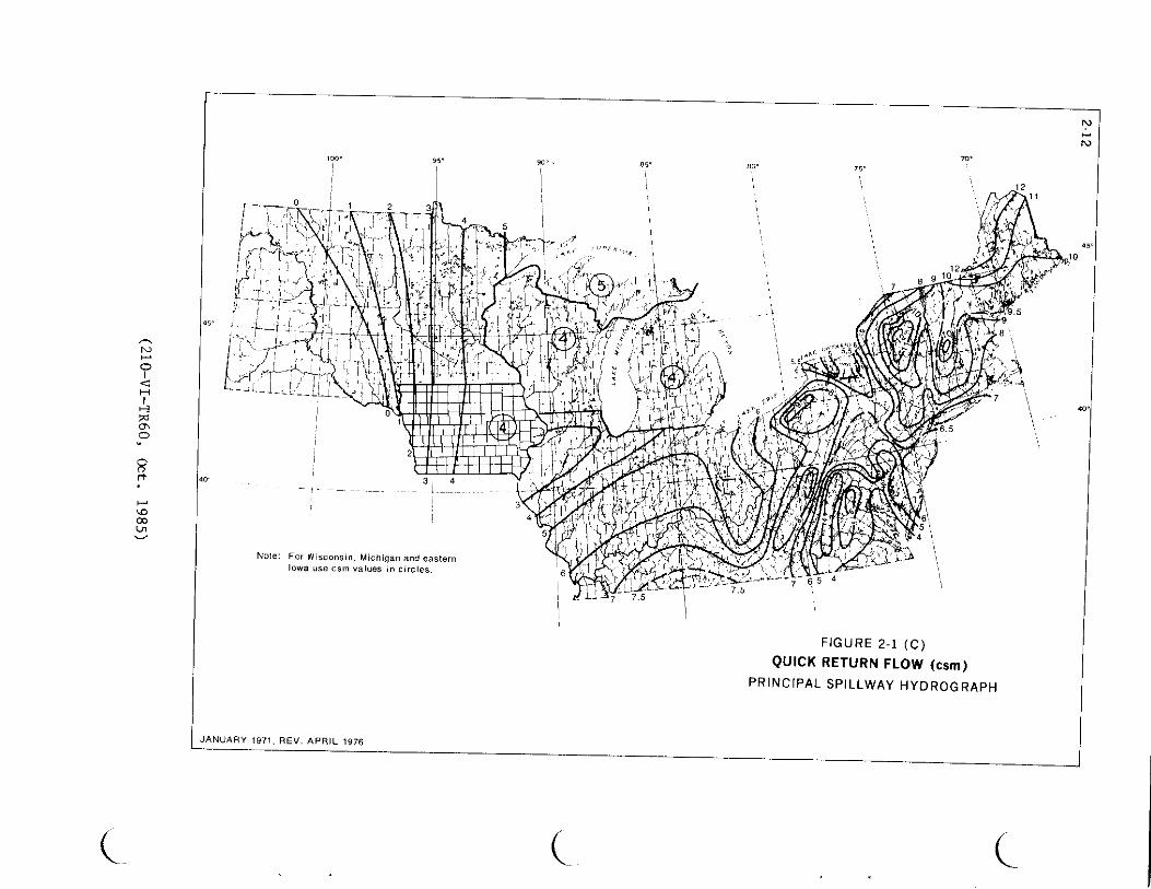

( ( (
middot1cent pi - _ smiddot efer nmiddotcmiddote -_fbifmiddot __ _ middotz~K ALAKAmiddotmiddotmiddot~~ c-Tec~~i~ per 4middot1 USWB Cl~~middot _ -~~dlpmet gtoglcaReport 54 (I 9~~ middot
1 1
[ HAWAlti~tJNDSlOo~dfmbulli~or~loglcal Rep~rt 39 ( 1963 FIGURE 2-5
~t_PJJ~Rro=RICO -middot~T~ch~cal Rp~rt42 USWB CI t6 PROBABLE MAXIMUM PRECIPITATIONI) and -middotmiddot- -lt-~r -
ivlRGIN ISLANDS f(bull middot middot NWS REFERENCESJUDY REGIONS N I i t~
JI-bull~~i ~~ ~h~-S f middotgt-
I ~~ ~1~J Ii 1 Aug I 9lf5 ~ ~- -_~-middot--~-~- 1 ~-m~___z__~- 1b~--~
N
_I
10 I I 11 I I I 10 ltXgt
~09 1- - 1 TPACIFIC C0iSTA1 CL~AT+- ~ I - ~ t _HUMID 4ND SU 09
a-_z-
OB -------- ---- -f -1 - BHUM10 CLIM4Tf -
~
_ --+ I 4~ + -= I--
_ I D Atvo ~E 07 08
St1i114 -_1 _ - ---- _J__J-- ~-i-i- I--- --- li10 Cl -_0 +-shy~ 06 ~ 11fq f-
lI - ~+- t-r- Pgt
Ir----+-- -- ---- =gt 6 0
c c t+050 15 x20 25 30 35 40 45 50 60 70 BO 90 100DRAINAGE AREA IN SQUARE MILES
0
I~u 0
~ I
_ A) AREAL PRECIPITATION ADJUSTMENTS FOR gt-z gtshy
Z
00DRAINAGE AREAS 10 to 100 SQUARE MILES J ~a ~
H ~~I ~rl
lt~04~ zshylti i0 0i== 00
~~ 00c c
llt o
deg 0 I00 ~~
~ gt-gtshy zz0
0
~
0 2 3 4 5 6~~ TIME IN HOURSzzlti lti (C) SIX HOUR DESIGN STORM DISTRIBUTION0~
FIGURE 2-6 12 18 EMERGENCY SPILLWAY AND FREEBOARD
TIME IN HOURS VOLUME ADJUSTMENTS AND STORM DISTRIBUTION(B) RELATIVE INCREASE IN RAINFALL AMOUNT
FOR AREAS WHERE NWS REFERENCES DO NOTFOR STORM DURATIONS OVER SIX HOURS CONTAIN AN APPLICABLE PROCEDUREAug 1981
(_ ( (
3-1
SEDIMENTATION
Reservoirs used to store or retard water from surface runoff will trap and store a large portion of the sediment in the runoff water Thereshyfore allocate storage capacity for the calculated sediment accumulation during the design life of the reservoir Criteria and general procedures needed to determine the volume required for sediment accumulation and its allocation in the reservoir are contained in NEH-3 Sedimentation and TR 12 The latter also includes procedures for determining
1 The sediment yield for present conditions and for the future after planned land treatment and other measures are applied in the drainage area of the dam
2 The trap efficiency of the reservoir
3 The distribution and types of sediment expected to accumulate
4 The proportion of the sediment that will be continously submerged vs that aerated and
5 The densities to which the sediment will become compacted
__ If the amount of sediment accumulation calculated exceeds two watershed inches in 50 years for the uncontrolled drainage area of the darn reevaluate the entire watershed to determine if more economical methods of reducing sediment yield or trapping sediment may be feasible and applicable
(210-Vl-TR60 Oct 1985)
4-1
GEOLOGIC INVESTIGATIONS
The intensity and detail of geologic site investigations are to be consistent with the class of dam complexity of site geology and the data needed for
design General requirements procedures and criteria are set forth in 210-V Part 531 and NEH-8
Geologic conditions that require special consideration beyond the minimum investigations spelled out in the above reference are
1 Seismic Assessment -- Dams in zones 3 and 4 Alaska Puerto Rico and the Virgin Islands and high hazard [class(c)] dams in zone 2 (see figure 4-1) require special investigations to determine liquefaction potential of noncohesive strata including very thin layers and the presence at the site of any faults active in Holocene time As part of this investigation a map is to be prepa-red showing the location and intens i tr of magnitude of all intensity V or magnitude 4 or greater earthquakes of record and any historically active faults within a 100 kilometer radius of the site (Obtain earthquake information for this map in printout form from the Environmental Data Service attention D62 NOAA Boulder Colorado 80302 Telephone FTS 323-6472 Commercial (303) 499-1000 ext 6472) The report should also summarize other possible earthquake hazards such as ground compaction landslides excessive shaking of unconsolidated soils seiches and in coastal areas tsunamis
2 Subsidence -- Investigate the potential for surface subsidence due to past or future solid liquid (including ground water) or gaseous mineral extraction Consult the state geological andor evaluation National Engineering Manual 210-V Part 531 Subpart D sets forth criteria for these evaluations
Evaluate the impact of the preemption of mineral deposits including sand and gravel by dams and reservoirs
In arid and semiarid areas and in eolean deposits determine the potential of moisture deficient soil materials to collapse upon saturation or wetting If the potential exists make extensive and intensive site investigations to provide quantitative information for design and construction
3 Emergency Spillways -- Large dams with emergency spillways in soft rock or cemented soil materials that cannot be classified as soil as defined Jn TR 52 nor as rock as generally defined for engineering purposes and spillways in rocks with extraordinary defects require a special individu1l evaluation
(210-VI-TR60 Oct 1985)
4-2
4 Mass Movements -- Evaluate landslides and landslide potential at dam and reservoir sites especially those in shales and where unfavorable dipshyslope or other adverse rock attitudes occur Summarize the history of mass movement in the project area Emergency spillway cuts and reservoir effects must be given careful consideration
5 Karstic areas -- Limestone and gypsum in reservoirs and at damsites require special investigational methods and careful evaluation of subsidence leakage hazards and construction costs Multipurpose structures in these areas are especially critical
6 Multipurpose Dams -- Investigate the ground water regime and hydraulic characteristics of the entire reservoir area of water storage dams and evaluate for leakage Use the water budgets to determine the need for reservoir sealing
7 Other -- Special studies and evaluations may be necessary where such things as compaction shales some types of siliceous calcareous or pyritic shales rebound joints dispersed soils or artesian waters occur at a site
(210-VI-TR60 Oct 1985)
( (
0 I lt I
rel ll
0 0 () rt
00 U1 deg
Minimum Seismic Coefficients
Zone Coefficients-0shy
1 005 2 010
3amp4 Base on Seismic Assessment
0 Q
SEISMIC ZONE MAP of
CONTIGUOUS STATES f w
0
Q
l
Adapted From TM 5-809-10 NAVFAC P-355 AFM 88-3 Chapter 13 April 1973
f KAUAI
~ 8LIHUE
OAHU ocE~N NllHAU
~ HONOLULU
MOLOKAI I----
KAUN~
LANAI Cl~~ ~
N ~
0 P~c1f c bullLANAI I
lt1 H KAHOOLAWE I gt-l_ 10 0 10 20 30 40
deg STATUTE MILES 0 0 (l rt
bullHILO ~ MinimlDil Seismic Coeficients 00 Ln ~
gt-bull OQ
Zone Coefficients
ro 0 0
1 005 I
gt- 2 010
romiddot ro
3amp4 Base on Seismic Assessment
rt
SEISMIC ZONE MAP 0
Hawaii
Adapted From TM 5-809-10 NAVFAC 0-355 AFM 88-3 Chapter 13 April 1973
( ( (
5-1
EARTH EMBAlKMENTS AND FOUNDATIONS
Earth embankments constructed of soil and rock are the principal means of impounding water The earth embankment and its foundation are to withstand the anticipated loads without movements leading to failure Measures are to be provided for adequate seepage control
Height
The design height of an earth embankment is to be sufficient to prevent overshytopping during passage of either the (1) freeboard hydrograph or (2) the emergency spillway hydrograph plus the freeboard required for frost condishytions or wave action whichever is larger The design height must also meet the requirements for minimum emergency spillway depth The design height of the dam is to be increased by the amount needed to compensate for settlement
Top Width
The minimum top width of embankment is shown in Table 5-1
Table 5-1
Minimum Top Width of Embankment
Total Height of Embankment
(feet) (H) All
Dams
Top Width Single Purpose
Floodwater Retarding
(feet) Multipurpose
or other Purposes
14 or less 8 15 - 19 10 NA NA 20 - 24 12 25 - 34 14
H + 35 35 - 95 NA 14 5 Over 95 NA 16 26
The width may need to be greater than the above minimums to (1) meet state and local standards (2) accommodate embankment zoning (3) provide roadway access and traffic safety and (4) provide structural stability An increase in top width is a major design feature in preventing breaching after embankshyment slumping caused by earthquake ground motion
When the embankment top is used as a public roadway the minimum width is to be 16 feet for one-way and 26 feet for two-way traffic Guardrailsmiddot or other safety measures are to be used and are to meet the requirementsof the responsible road authority
(210-VI-TR60 Oct 1985)
5-2 Embankment Slope Stability
Analyze the stability of embankment slopes using generally accepted methods based on sound engineering principles Document all analyses or considerations in appropriate design reports and files Design the embankment cross section to provide adequate factors of safety against sliding sloughing or rotation in the embankment and foundation Use the appropriate degree of conservatism in the analysis that is consistent with the adequacy of the site investigation and soil testing program and with the complexity of the site and consequences of failure Minimum factors of safety are listed in table 5-2
Evaluate the effect of seismicity on each site Include the determination of whether the site is in a seismically active area its proximity to active faults and the predicted site ground motion intensity Use the minimum seismic coefficient shown in Figure 4-1 in the slope stability analysis when no special seismic assessment is made
Analyze embankment slope stability for the conditions and periods during the design life of the structure that are most critical or severe Use conditions in the analysis based on possible critical water levels and loadings of the embankment and foundation Consider and document the following conditions or periods (1) end of construction (2) steady seepage (3) rapid drawdown and (4) during seismic loading Use the shear strength parameters and minimum factors of safety indicated in Table 5-2 for each case The nomenclature for the various shear strength tests is listed in Table 5-3
Calculate the factor of safety based on the ratio of the shear strength available to the shear strength mobilized
Clearly document the conditions not analyzed correlated shear strength parameters or correlation to field performance
Consider the following additional details in conjunction with Table 5-2
I End of Construction Make a detailed analysis of this case when significant pore pressure development during construction is expected in either the embankment or foundation soils Embankment soils are to be tested at the highest likely placement water content and foundation soils are to be tested at saturation Select shear strength parameters according to Table 5-2
II Rapid Drawdown Analyze the stability of the upstream embankment slope for the condition created by a rapid drawdown of the water level in the reservoir Use a phreatic surface in the embankment developed from the emergency spillway crest with the water level in the reservoir drawn down to the crest of the lowest gated or ungated outlet Failure surfaces are to be confined to the embankment only if foundation soils are free-draining Use infinite slope stability equation appropriate to drainage conditions of the embankment soils whenever the c or c value being used in the analysis is zero In addition to the infinite slope analysis circular arch or sliding wedge analyses may be needed to check stability where failure surfaces could extend into weaker core
(210-VI-TR60 Oct 1985)
5-3
zones or into the foundation Select shear strength parameters according to Table 5-2
III Steady Seepage Without Seismic Forces Analyze the downstream slope for the condition of steady seepage developed from the water surface at the principal spillway crest In the analysis saturated soils will be subjected to uplift forces simulated by a piezometric surface developed from the emergency spillway crest Phreatic surfaces and piezometric surfaces may be developed using flow nets or Casagrande procedures Select shear strength parameters according to Table 5-2
IV Steady Seepage With Seismic Forces Analyze the downstream slope for the condition of steady seepage developed from the water surface at the principal spillway crest with a horizontal force equal to the effective weight multiplied by the earthquake coefficient applied at the failure surface (pseudo-static analysis) Uplift forces due to the reservoir at the emergency spillway level need not be included because of the very remote potential for the simultaneous occurrence of an earthquake and an emergency spillway storm event A two or three dimensional computer analysis may be used instead of a pseudo-static analysis if desired Select shear strength parameters according to Table 5-2
V Steady Seepage With and Without Seismic Forces Determine the results of the analysis using either the total stress or effective stress shear strength parameters that are the most limiting (those resulting in the lowest factor of safety) Analyses are to include the use of various combinations of total stress parameters in certain zones and effective stress parameters in other zones The combinations that may be most limiting can usually be narrowed to one or two by inspection and judgement without analyzing all possible combinations
VI Additional Guidance
A Effective stress shear strength parameters are generally the most limiting for any free draining soil
B Total stress shear strength parameters are generally most limiting for non-free draining foundation soils that exhibit positive pore pressure buildup during undrained shear testing
C Effective stress shear strength parameters are generally most limiting for non-free draining foundation soils that exhibit negative pore pressure buildup during undrained shear testing
D Analyses will generally have to be made using both total and effective stress shear parameters to determine the most limiting for non-free draining embankment soils that exhibit either small negative or positive pore pressures during undrained shear testing
E Effective stress shear strength parameters are generally most limiting for non-free draining embankment soils that exhibit highly negative pore pressures during undrained shear testing
F Total stress shear strength parameters are generally most limiting for non-free draining embankment soils that exhibit highly positive pore pressures during undrained shear testing
(210-VI-TR60 Oct 1985)
TABLE 5-2 SLOPE STABILITY CRITERIA FOR DAMS
Design Condition Primary Assumption Remarks Minimum Factor ___o_f__s a tot v
I bull End of construcshytion (upstream or downstream slope)
Significant construction pore pressures expected in cert a In zones of the embank~
ment or layers In the foundation
1
2
Embankment conshyta In 1ng Impershyvious sol Is at water contents aqua I to or greatagtr than optimum water content andor Saturated Impershyvious foundation strata too thick to tully consolishydate duriog construction
uu I 4 ( 13 ls acceptshyable for embankshyments on strong foundations Ie the fal lure surshyf ace Is I ocated entirely In the embankment)
Peryen1ous embankment zones andor foundashyt I on strata
CiT or CD
I I Rapid drawdown (upstream slope)
Drawdown sp 111 way
from the crest to
emergency the crest
Fa 11 ure surface can be confined to the
Use alternative I or 2 below -
1 2
of the ungated
lowest gated outlet
or embankment or extend Into the foundation 1 Lowest shear If low permeability sol ls are Involved
strength from composite enveshylope of CU and CiT
or
2 Most IJr_ltlng3 of CU or CU or a combination ot both
(For alternative 2 only use shear strength tat lure crterle ot 01+03 maximum for dilative soils tested with backpressure saturation techniques This Is to avoid rel lance on high coh~shyslon developed by negative pore presshysure as a result of water tension)- --~-------------------middotmiddot-middot--------------- ---------------middot------ ___________________________
NOTE See bottom of next sheet tor explanatfon of footnotes
(210-VI-TR60 Oct 1985)
(_
( ( (
TABLE 5-2 (Contd) SLOPE STABILITY CRITERIA FOR DAMS
Design Condition Primary Assumption Remarks Shear strength Minimum Factor To Be Used 12 of Safety-
I I I bull Steady seepage I bull Water surf ace at the Fal lure surface con- nr or CD 1 bull 5 without seismic principal spillway f In ed to the embank-forces (down- crest and phreatic ment on I y stream s 1ope) surface f u I I y developed
through the embankment
2 Plezometrlc surface for Fal lure surface Most I Jmitlng3 of cu 1 bull 5 estimating up I If t In extends Into the or m or a comb Ina-saturated so I I zones Is foundation tlon of both determined with water level at the emergency spillway crest
IV Steady seepage 1 bull Water surface at The Fal lure plane may be Most I imlting3 ot CU 1 bull 1 with seismic crest of the principal cont I ned to the or C1T or a comblnashyforces Cd own- spi 1 lway and phreatlc embankment or may tlon of both stream slope) surface f u I I y developed extend Into the
through the emban-kment foundation
1 Use CU or CD shear strength tor pervlous sol I zones within the foundation or embankment
2 Use Infinite slope stabl I lty analysis whenever the C or C Intercept strength Is zero tor so I Is that are -tested to simulate low cont In Ing pressures This situation exists for tal lure surfaces located near the embankment surface Minimum factor ot safety for the Infinite slope stability analysis Is 11
3 Most llmltlng Is the combination resulting In the lowest factor ot safety
n I
n
(210-VI-TR60 Oct 1985)
5-6
TABLE 5-3
NOMENCLATURE OF SHEAR STRENGTH TESTS
Test Parameters scs Common Condition Obtained Descriltion Abbreviation
Unconsolidated Total Y uu Q Undrained Stress
Consolidated Total Y cu R Undrained Stress
Consolidated Effective _I cu R Undrained with Stress pore pressures measured
Consolidated Effective Y CD ii s Drained Stress
ll Total stress shear strength parameters are determined when no drainage is allowed during the test using the external stresses imposed on the soil specimen When used in a total stress analysis the assumption made is that the pore pressure developed (negative or positive) during loading is the same in the laboratory as it is in the field
_I Effective stress parameters are determined from undrained tests by using the intergranular stresses (total stress minus the pore water stress) on the soil particles When used in an effective stress analysis any effects of pore pressure development (positive or negative) resulting from load application must be accounted for in the analysis
ii The CD tests allow drainage during load application If the load is applied slow enough complete drainage occurs so that no pore pressure develops and the shear strength parameters obtained should be the same as CU parameters
(210-VI TR60 Oct 1985)
5-7
Seepage
To the extent needed an analysis is to be made of anticipated seepage rates and pressures through the embankment foundation abutments and reservoir perimeter (when storage is desired) Controls and treatment should be adequate to (1) accomplish the intended reservoir function (2) provide a safely operating structure and (3) prevent damage to downstream property
Zoning
Embankment zoning can be used when needed to (1) obtain a stable structure with the most economical use of available materials (2) control seepage in a safe manner or (3) reduce to a minimum the uncertainties of material strengths and resultant stability
Embankment zones should be a minimum of 10 feet wide except for filters and drains with specified and controlled gradation Drains and filters should meet the requirements contained in Soil Mechanics Notes
Soil materials which exhibit significant shrinkage swell or dispersion are to be used only with extreme care If possible they should not be used for embankment construction When there is no economical alternative to their use they are to be (1) treated to improve their performance (2) placed in zones where effects will not be detrimental or (3) protected by use of filters and drains or self-healing transition zones
Surface Protection
Embankment surfaces are to be protected against surface erosion Protection may be vegetative gravel rock riprap soil cement structural or similar treatment of durable quality and proven satisfactory performance
Vegetative Protection Vegetative protection may be used on surfaces where the following conditions can be met (1) inundation of the surfaces is of such frequency that vegetative growth will not be inhibited (2) vigorous growth can be sustained under average climatic conditions by normal maintenance without irrigation and (3) stable protection can be designed according to the procedures in TR-56
Structural Protection Protection against wave erosion by riprap or other structural measures is to be provided as follows (1) for dams where vegetation will not provide effective control (2) for multiple purpose dams and (3) for dams with fluctuating normal water levels
Protection is to extend from the lowest drawdown elevation that presents an erosion hazard to a few feet above the crest of the lowest ungated spillway The upper limit is to be based on an analysis of anticipated wave height and run up
Quality of riprap and other structural protection is to be consistent with the anticipated life of the dam and designed to be structurally stable
(210-VI TR60 Oct 1985)
6-1
PRINCIPAL SPILLWAYS
The structural design and detailing of principal spillways are to conform to the recommendations of National Engineering Handbook Section 6 Structural Design and SCS standard drawings All component parts of principal spillways except easily replaceable parts such as gates and trash racks are to be equally durable
Capacity of Principal Spillway
The required capacity of the principal spillway depends on (1) purpose of the dam (2) the amount of storage provided by the retarding pool (3) the kind of emergency spillway (4) stream channel capacity and stability downstream (5) potential damage from prolonged storage in the retarding pool (6) potential damage downstream from prolonged high outflow rates (7) possibility of substantial runoff from two or more storms in the time required to empty the retarding pool (8) limitations imposed by water rights or other legal requirements (9) environmental concerns (10) planned or potential alterations of the channel downstream and (11) the necessity to pass base and flood flows during construction
The principal spillway may be single-stage having an ungated inlet at only one elevation or multiple-stage having inlets at two or more elevations In the case of multiple-stage spillways the lower stage or stages usually perform the primary flood control function and the high stage has the capacity needed to prevent the emergency spillway from functioning more frequently than permissible
The principal spillway capacity should be adequate to empty the retarding pool in 10 days or less This requirement is considered to be met if 15 percent or less of the maximum volume of retarding storage remains after 10 days Where low release rates are required to meet the objectives of the project a longer period than 10 days may be needed For these situations additional storage is required to minimize the opportunity for increased frequency of emergency spillway flow due to recurring storms
Compute the 10-day drawdown from the time the maximum water surface elevation is attained during the passage of the principal spillway hydrograph The entire design inflow hydrograph including quick return flow upstream releases and outflow are to be considered in determining the evacuation time of the retarding storage The inflow from storm runoff must be considered for the entire evacuation time
For dams where more than 15 percent of the retarding storage volume remains after 10 days the elevation of the crest of the emergency spillway will be raised The raised crest elevation is determined by adding the remaining retarding storage volume to the initial retarding storage volume
(210-Vl-TR60 Oct 1985)
6-2
Elevation of Principal Spillways
Single Purpose Floodwater Retarding Dams The crest of the principal spillway or of the low stage inlet of a two-stage principal spillway is to be set at the sediment pool elevation For dry dams the elevation of the principal spillway inlet is to be placed as described above and provisions are to be made to drain the reservoir in a reasonable time and thus satisfy the functional or legal requirements of the dam
Other Dams When conservation storage is to be provided the elevation of the crest of the lowest ungated inlet of the principal spillway is to be determined by the volume area or depth of water required for the planned purpose or purposes and the required sediment storage The lowest crest may be the crest of the low-stage inlet single-stage inlet or an open spillway
Routing of Principal Spillway Hydrographs
Reservoir flood routing used to proportion dams and associated spillways is to be based on the assumption that all sedimentation expected in the reservoir during its design life has occurred The reservoir stage-storage curve used for routing should reflect the anticipated accumulation of sediment The initial reservoir stage for principal spillway hydrograph routing is to be at the crest of the lowest ungated inlet or (if not subtracted from the stage-storage curve) the anticipated elevation of the sediment storage whichever is higher except as provided in items 1 2 and 3
1 For dams with significant base flow principal spillway hydrograph routings must start not lower than the elevation of the water surface associated with the base flow Significant base flow is average annual or seasonal flow that would produce at least 05 feet of head over the lowest principal spillway inlet immediately prior to a flood or occupy more than 10 percent of the floodwater storage capacity
2 For dams with joint use storage capacity when one of the uses is floodwater detention routing of the principal spillway hydrograph may begin at the lowest anticipated elevation of the joint use pool in accordance with the operation plan
3 Single purpose class (a) irrigation dams with gated outlets and earth or vegetated emergency spillways which are located on ephemeral streams in areas where the average annual precipitation is less than 25 inches may be considered to have discharged up to 70 percent of the storage exculsive of sediment storage in determining the elevation to start routing
Design of Principal Spillways
Hydraulics The principal spillway is to be designed to carry the planned flow for expected head and tailwater conditions TR-29 Design Note No 8 NEH-5 the Engneering Field Manual for Conservation Practices and other appropriate references are to be used for hydraulic design
(210-VI-TR60 Oct 1985)
6-3
Risers Risers for drop inlet spillways are to be designed to maintain the reservoir pool level at or near the inlet crest elevation during low flow periods to establish full pipe flow at as low a head over the crest as practical and to operate without excessive surging noise vibration or vortex action at any reservoir stage Ibis requires the riser to have a larger cross sectional area than the conduit Standard risers have an inside width equal to the width (diameter) D of the conduit and an inside length equal to three times the width (diameter) of the conduit (D x 3D cross section)
Risers are to be designed to exclude trash too large to pass freely through the spillways including the outlet structure and to facili shytate the passage of smaller trash Standard D x 3D risers tend to line up longer pieces of trash and facilitate their passage into and through the conduit Covered risers with standard skirted or baffle inlets should be used in most cases because they are most effective in excluding trash without becoming clogged Skirted inlets having a cover with skirts extending below the weir crest elevation are applicable where backfill or settlement levels are to be at least two times the conduit width (diameter) below the crest Baffle inlets are applicable for risers that are to be backfilled to the crest eleshyvation or where sediment is expected to build up to the crest elevation
Risers are to be designed structurally to withstand all water earth ice and earthquake loads to which they may be subjected Articulation is to be provided to allow movement of the riser with respect to the conduit
Risers with low-stage inlets at or near the bottom are to be provided with concrete aprons to prevent erosion of soil and undermining of the riser footing by high velocity flow approaching the inlet
Standard risers are to be used where applicable for class (a) dams with an effective height of more than 35 feet and for all class (b) and class (c) dams Prefabricated pipe risers are permissible where hydraulically and structurally adequate for class (a) dams not more than 35 feet in effective height The riser pipe is to be of the same material as the conduit and at least one standard pipe size larger then the conduit pipe
Special riser designs are required for spillways having maximum conduit velocities more then 30 feet per second and for spillways having conduits larger then 48 inches in width (diameter) Generally these should be similar to standard risers but a special elbow and transition is required at the junction of the riser and conduit and special design of the inlet may be necessary Hydraulic model testing should be considered if the maximum total head on the spillway is more than 75 feet or the conduit velocity exceeds 50 feet per second
(210-Vl-TR60 Oct 1985)
6-4
Conduit The conduit should be straight in alignment when viewed in plan Changes from straight alignment if required are to be accomplished by watertight angle changes at joints or by special elbows having a radius equal to or greater than the diameter or width of the conduit Thrust blocks of adequate strength are to be provided if special pipe elbows are used They are to be designed to distribute the thrust due to change in direcshytion for the maximum possible discharge Drop inlet conduits are to be installed with enough slope to insure free drainage to the outlet of all parts of the conduit (including camber) at the time of construction and under the maximum anticipated settlement
All condbull1its under earth embankments are to support the external loads with an adequate factor of safety They are to withstand the internal hydraulic pressures without leakage under full external load and settlement They are to convey water at the design velocity without damage to the interior surface of the conduit
Principal spillway conduits under earth dams may be designed to support fill heights greater than the original constructed height if there is a reasonable possibility that the embankment height may be raised later to incorporate additional storage for some approved beneficial use
Rigid principal spillway conduits are to be designed as positive projecting conduits in accordance with the principles and procedures given in TR-5
Principal spillway conduits are to be of reinforced concrete pressure pipe or cast-in-place reinforced concrete unless corrugated steel or welded steel pipe is used in accordance with subsection 2 which follows
Cast-in-place rectangular reinforced concrete conduits are to be designed in accordance with principles and procedures in TR-42 TR-45 or other appropriate design aids
For Reinforced Concrete Water Pipe - - Steel Cylinder Type Prestressed ~eting specification AWWA C301 the 3-edge bearing strength at the first 0001-inch crack is to be used with a safety factor of at least one
For Reinforced Concrete Water Pipe - - Steel Cylinder Type Not Prestressed meeting specification AWWA C300 for Reinforced Concrete Water Pipe -Noncylinder Type Not Prestressed meeting specification AWWA C302 and for other types of reinforced concrete pipe the 3-edge bearing strength at the first 001-inch crack is to be used with a safety factor of at least 133
Elliptical or other systems of reinforcement requiring special orientation of pipe sections are not permitted in spillway conduits
Reinforced concrete pipe is to be designed to support at least 12 feet of earth fill above the pipe at all points along the conduit
(210-VI-TR60 Oct 1985)
6-5
1 Reinforced Concrete Pipe - (A) Minimum Inside Diameters on Yielding Foundations Class (a) dams The minimum diameter of the principal spillway conduit is to be 30 inches unless a joint extension safety margin of at least 15 inches is used in which case the minimum diashymeter is to be 18 inches for maximum fill heights up to 50 feet at the centerline of the dam and 24 inches for greater fill heights
Class (b) dams The minimum diameter of the principal spillway conduit is to be 30 inches unless a joint extension safety margin of 15 inches is used in which case the minimum diameter is to be 24 inches
Class c) dams The minimum diameter of the principal spillway conduit is to be 30 inches
(B) Minimum Inside Diameters on Non-Yielding Foundations The minimum diameter of the principal spillway conduit for class (a) dams is to be 18 inches for heights up to 50 feet at the centerline of the dam and 24 inches for heights greater than 50 feet and 24 inches for all class (b) and (c) dams The conduit and cradle or bedding are to rest directly on firm bedrock thick enough so that there is essenti shyally no foundation consolidation under the conduit Under these conditions the cradle or bedding under the conduit need not be articulated
2 Corrugated Steel Pipe or Welded Steel Pipe - Principal spillways of corrugated steel or welded steel pipe may be used for single purpose class (a) dams with the product of storage times effective height of dam less than 10000 While installation costs of steel pipes may be less concrete may compare favorably with steel when replacement costs and associated problems are considered
In each case the following limitations apply
a Diameter of pipe not less than 18 inches b Height of fill over the pipe not more than 25 feet c Provision for replacement if the materials will not
last for the design life of the structure d Pipe structurally strong enough to withstand outside
loads and hydraulic pressure e Pipe Watertight
Corrugated steel pipe is to be close riveted asbestos treated and asphalt coated with watertight connecting bands The minimum gage is to be that designed for 35 feet of fill over the pipe
Welded steel pipe conduits are to be structurally designed as rigid pipe A joint extension safety margin of 15 inches is to be provided for conduits on yielding foundation Welded steel pipe is to be protected by a Class A exterior coating as defined in the specifications guide for steel irrigation pipeline Engineering Practice Standard 432-F (NEH-2) or by an exterior coating of coal tar-epoxy paint conforming to Paint System I Construction Specification 82 (NEH 20)
(210-VI-TR60 Oct 1985)
Joints between lengths of corrugated steel or welded steel pipe other than welded joints are to be electrically bridged on the outside of the pipe with insulated copper wire 6 AWG or larger securely attached to the uncoated pipe metal at both sides of the joint This requirement applies whether or not the cathodic protection is completed by the installation of anodes etc The wire s hould have a tough waterproof insulation designed for direct burial with a rating of at least 600 volts Bare wire and exposed pipe metal at the points of connection are to be thoroughly coated with a coating equivalent to the original pipe coating to prevent the entry of moisture
Soil investigations for resistivity and pH of the subgrade and backfill materials to be adjacent to the condui t are to be made The resis t ivity measurements are to be made on saturat ed samples
Cathodic protection is to be provided for welded steel pipe conduits according to the criteria in Engineering Practice Standard 432-F (NEH-2) and 432-F specifications guide
Cathodic protection meet i ng the above r equirements i s to be provided for corrugated steel pipe in soil whose resistivity in a saturated condition is less than 4000 ohms-cm or whose pH is lower than 5 0
If cathodic protection is not required according to the above criteria and anodes are not installed during construction of the dam pipe- to-soil potentials are to be measured within the first 2 years after construction or after the water level has stabilized and when t he soil around the conduit is estimated to be at its normal post-construction moisture content Cathodic protection is to be installed at this time if such measurements indicate it is needed
Joints Conduit joints are to be des i gned and constructed to remain watertight under maximtun anticipated hydrostatic head and maximum probab l e joint opening as computed from Standard Drawing ES- 146 and r e l ated procedures of TR 18 including the effects of joint rotation and the required margin of safety The required joint extensibility is equal to the unit horizontal strain in the earth adjacent to the conduit multipl i ed by the length (in inches) of the section of conduit between joints plus the extension (in inches) due to calculated joint rotation plus a margin of safety
A margin of safety of not less than 05 inch shall be used The required joint extensibility plus the maximum permissible joint gap equals the required joint length The required joint extensibility depends on the maximum
potential foundation consol i dation under the spillway barrel For class (b) and (c) dams the consolidation is to be estimated f r om adequate founshydation borings and samples soil mechanics l aboratory tes ts and engineering analysis For class (a) dams where undis turbed foundation samples are not taken for other purposes approximate procedures based on soil classification and experience may be used for estimating foundation consolidation
(210-VI-TR60 Oct 1985)
6-7
Only joints incorporating a round rubber gasket set in a positive groovewhich will prevent its displacement from either internal or external pressure under the required joint extensibility are to be used on precast concrete pipe conduits Concrete pipe must have steel joint rings providing rubber to steel contact in the joint
Articulation of the conduit (freedom for required rotation) is to be provided at each joint in the conduit at the junction of the conduit with the riser and any outlet structure Concrete bedding for pipe conduits need not be articulated Cradles are to be articulated if on yielding foundations Welded steel pipe conduits need not be articulated if the pipe and bedding rest directly on firm bedrock
Piping and Seepage Control - Use a filter and drainage diaphragm around any structure that extends through the embankment to the downstream slopeDesign the diaphragm with single or multizones to meet the requirements of Soil Mechanics Note No 1
Locate the diaphragm aligned approximately parallel to the centerline of the dam or approximately perpendicular to the direction of seepage flow Extend the diaphragm horizontally and vertically into the adjacentembankment and foundation to intercept potential cracks poorly compactedsoil zones or other discontinuities associated with the structure or its installation
Design the diaphragms to extend the following minimum distances from the surface of rigid conduits
l Horizontally and vertically upward 3 times the outside diameter of circular conduits or the vertical dimension of rectangular box conduits except that
a the vertical extension need be no higher than the maximum potential reservoir water level and
b the horizontal extension need be no further than 5 feet beyond the sides and slopes of any excavation made to install the conduit
2 Vertically downward
a for conduit settlement ratios (o) of 07 and greater (reference SGS Technical Release No 5) the greater of (l) 2 feet or (2) 1 foot beyond the bottom of the trench excavation made to install the conduit Terminate the diaphragm at the surface of bedrock when it occurs within this distance Additional control of general seepage through an upper zone of weathered bedrock may be needed
b 15 times the outside diameter of circular conduits or the outside vertical dimension of box conduits for conduit settlement ratios (o) less than 07
(210-VI-TR60 Revised Amend 1 Oct 1990)
6-8
Design the diaphragms to extend in all directions a minimum of 2 times the outside diameter from the surface of flexible conduits except that the diaphragm need not extend beyond the limits in la and lb above nor beyond a bedrock surface beneath the conduit
Provide minimum diaphragm thickness of 3 feet and minimum thickness of 1 foot for any zone of a multizone system Use larger thickness when needed for (1) capacity (2) tieing into embankment or foundation drainage systems (3) accommodating construction methods or (4) other reasons
For homogeneous dams locate the diaphragm in the downstream section of the dam such that it is
1 Downstream of the cutoff trench
2 Downstream of the centerline of the dam when no cutoff trench is used and
3 Upstream of a point where the embankment cover (upstream face of the diaphragm to the downstream face of the dam) is at least one-half of the difference in elevation between the top of the diaphragm and the maximum potential reservoir water level
For zoned embankments locate the diaphragm downstream of the core zone andor cutoff trench maintaining the minimum cover as indicated for homogeneous dams When the downstream shell is more pervious than the diaphragm material locate the diaphragm at the downstream face of the core zone
~ Lt is good practiceto tie these diaphragms into the other drainage systems in the embankment or foundation Foundation trench drains andor embankment chimney drains that meet the minimum size and ~ocation limits are sufficient and no separate diaphragm is needed
Design the minimum capacity of outlets for diaphragms not connected to other drains by assuming the coefficient of permeability (k) in the zone upstream of the diaphragm is 100 times the coefficient of permeability in the compacted embankment material Assume this zone has a cross-sectional area equal to the diaphragm area and the seepage path distance equal to that from the embankment upstream toe to the diaphragm This higher permeability simulates a sealed filtet face at the diaphragm with partially filled cracks and openings in the upstream zone
For channels chutes or other open structures seepage and piping control can be accomplished in conjunction with drainage for reduction of uplift and water loads The drain properly designed to filter the base soils is to intercept areas of potential cracking caused by shrinkage differential settlement or heave and frost action These structures
9 US Government Printing Office 1991 - 282-95740388
(210-VI-TR60 Revised Amend 1 Oct 1990)
- ~ -
6-9
usually require the use of footings keywalls and counterforts and drainage is properly located iDBDediately downstream of these features This drainage when properly designed can control pip1ng and provide significant economies due to the effect on soil loads uplift pressures overturning forces and sliding stability
Outlets
The choice of outlet is to be based on a careful consideration of all site and flow conditions that may affect operation and energy dissipation
1 Cantilever outlet and plunge pools may be installed where their use
a Does not create a piping hazard in the foundation of the structure
b Is compatible with other conditions at the site
Plunge pools are to be designed to dissipate the energy and be stable Unless the pool is to be in bedrock or very erosion resistant materials riprap will be necessary to insure stability Design Note 6 entitled Armored Scour Hole for Cantilever Outlet is to be used for design
Cantilever outlets are to be supported on bents or piers and are to extend a minimum of 8 feet beyond the bents or piers The bents are to be located downstream from the intersection of the downstream slope of the earth embankment with the grade line of the channel below the dam They are to extend below the lowest elevation anticipated in the plunge pool The invert of the cantilever outlet is to be at least 1 foot about the tailwater elevation at maximum discharge
2 SAF basins may be used when there is adequate control of tailwater Use TR-54 for structural design and NEH-14 for hydraulic design
3 Impact basins may be used when positive measures are taken to prevent large debris from entering the conduit TR-49 is to be used for hydraulic design
Trash Racks
Trash racks are to be designed to provide positive protection against clogging of the spillway under any operating level The average velocity of flow through a clean trash rack is not to exceed 25 feet per second under the full range of stage and discharge Velocity is to be computed on the basis of the net area of opening through the rack
If a reservoir outlet with a trash rack or a ported concrete riser is used to keep the sediment pool drained the trash rack or riser is to extend above the anticipated sediment elevation at the riser to provide
(210-VI-TR60 Oct 1985)
for full design flow through the outlet during the design life of the dam The velocity through the net area of the trash rack above the maximum sediment elevation must not exceed 2 feet per second when the water surface in the reservoir is 5 feet above the top of the trash rack or riser inlet
Antivortex Device
All closed conduit spillways designed for pressure flow are to have adequate antivortex devices
High Sulfate Areas
Under certain conditions concrete is susceptible to deterioration from sulfate ions especially those derived from sodium and magnesium sulfates In areas where experience or soil tests indicate the potential for problems the following table will be used for design purposes
Sulfate Concentration (parts per million) Hazard Corrective Measures
0 - 150 Low None
150 - 1000 Moderate Use Type II Cement (ASTM C-150) Adjust mix to protect against sulfate action
1000 - 2000 High Use Type V Cement (ASTM C-150) Adjust mix to protect against sulfate action Use soils in contact with concrete surfaces that are low in sulfates
2000 - up Do not use concrete materials unless measures are taken to protect concrete surfaces from sulfates Product manufacturers should be consulted
Sulfate concentration is for soil water at the concrete surface
7-1
EMERGENCY SPILLWAYS _
Emergency spillways are provided to convey excess water through over or around a dam They are usually open channels excavated in natural earth earthfill rock or constructed of reinforced concrete
Closed Type Spillways
An open channel emergency spillway is to be provided for each dam except as provided below
1 Class (a) dams with a product of storage times the effective height of the dam of less than 10000 - A closed conduit principal spillway havshying a conduit with a cross-sectional area of 12 square feet or more an inlet which will not clog an elbow designed to facilitate the passage of trash and large enough to pass the routed freeboard hydrograph is the minimum acceptable design without an open channel emergency spill shyway The minimum capacity will be taken from Figure 7-1
2 Dams with drainage areas of 10 square miles or less (except those covered by item 1) - A closed conduit principal spillway having a conduit with a cross-sectional area of 20 square feet or more an inlet which will not clog an elbow designed to facilitate the passage of trash and large enough to pass the routed f reeboard hydrograph peak discharge without overtopping the dam is the minimum acceptable design without an open channel emergency spillway In no case is the capacity of the spillway provided to be less than that determined from Figure 7-1
3 Dams with drainage areas greater than 10 square miles (except those covered by item 1) - A closed type primary emergency spillway may be used in lieu of an open channel emergency spillway Drop inlet spill shyways with a standard two-way covered top inlet are to have a minimum unobstructed cross-sectional area of each opening of the conduit of 40 square feet All other closed type primary emergency spillways are to have a minimum unobstructed cross-sectional area of each opening of 80 square feet The ratio of width to height in both cases is to be between 075 and 133 The spillways must be large enough to pass the routed freeboard hydrograph peak discharge without overtopping the dam In no case is the capacity of the primary emergency spillway provided to be less than that determined from Figure 7-1
Spillway Requirements
Capacity of Emergency Spillways Emergency spillways are to be proportioned so they will pass the emergency spillway hydrograph at the safe velocity determined for the site They are to have sufficient capacity to pass the freeboard hydrograph with the water surface in the reservoir at or below the elevation of the design top of the dam In no case is the capacity of the emergency spillway to be less than that determined from Figure 7-1 The minimum difference in
(210-Vl-TR60 Oct 1985)
7-2
elevation between the crest of the emergency spillway and the settled top of the dam is three feet
State law may establish minimum capacity or depth greater than those given above
Elevation of the Crest of the Emergency Spillway Table 2-2 Page 2-6 gives the maximum allowable frequency of use of earth and vegetated emergency spillways The minimum retarding storage volume and the associated principal spillway discharge are to be such that (1) the discharge through the emergency spillway will not occur during the routing of the principal spillway hydrograph and (2) the 10-day drawdown requirement is met or the crest elevation of the emergency spillway is raised as noted on page 6-1 Capacity of Principal Spillway
For earth spillways it refers to sites where peak flows of short duration may be expected and where erosion resistant soils and moderate slopes exist When vegetated spillways are used the sites must have these same characteristics and in addition conditions must be such that vigorous vegetation can be maintained without irrigation When conditions are less favorable emergency spillways are to be designed for less frequent use This may be done by (1) raising the crest elevation (2) increasing the capacity of the principal spillway (3) adding a structural primary emergency spillway or (4) a combination of the above
The maintenance required for the emergency spillway will be increased as the frequency and duration of flow increase Good design requires balancing the spillway maintenance cost against the increased cost of modifying the other elements of the dam to reduce the flow frequency
Emergency Spillway Routings The emergency spillway and the f reeboard hydrographs are to be routed through the reservoir starting with the water surface at the elevation of the lowest ungated principal spillway inlet the anticipated elevation of the sediment storage the elevation of the water surface associated with significant base flow or the pool elevation after 10 days of drawdown from the maximum stage attained when routing the principal spillway hydrograph whichever is higher except as provided in items 1 and 2
1 Dams with gated spillways and joint use storage capacity - Emergency spillway and freeboard hydrograph routings are to be started at or above the elevation of the lowest ungated outlet or at the elevation of the water surface associated with the average annual base flow whichever is higher
2 Single purpose class (a) irrigation dams - Emergency spillway and freeboard hydrograph routings are to be started at or above the water surface elevation of the irrigation storage
(210-VI-TR60 Oct 1985)
7-3
Hydraulic Design The relationship between the water surface elevation in the reservoir and the discharge through the emergency spillway is to be evaluated by computing the head losses in the inlet channel upstream of the control section or if a control section is not used by computing the water surface profile through the full length of the spillway Bernoullis equation and Mannings formula are to be used to evaluate friction losses compute water surface profiles and determine velocities Policy on the selection of n11 values is given in the discussion of the various types of emergency spillways
Structural Stability The spillway is to be investigated analyzed designed and constructed adequately to establish and maintain stability during the passage of design flows without blockage or breaching Excavated open cut spillways arr to have cut and fill slopes in earth and rock which are stable against slmiddotding Cut slope stability is to be evaluated for the long term weathered natural moisture condition and for adverse moisture conditions associated with rapid drawdown from the emergency spillway design discharge
Vegetated and Earth Emergency Spillways
Vegetated and earth emergency spillways are open channels and usually consist of an inlet channel a control section and an exit channel Subcritical flow exists in the inlet channel and the flow is usually supercritical in the exit channel
Vegetated emergency spillways are usually trapezoidal in cross-section and are protected from damaging erosion by a grass cover They are adapted to sites where a vigorous grass growth can be sustained by normal maintenance without irrigation
Earth spillways are used in those areas where vegetative growth cannot be maintained They are similar to vegetated spillways but are designed for lower permissible velocities and less frequent use Normally they will require more maintenance after a flow occurs
Earth and vegetated emergency spillways are designed on the basis that some erosion or scour may be permissible if its occurrence is infrequent if maintenance facilities are provided and the spillway will not breach during passage of the freeboard storm
TR 2 outlines layout procedures and TR 39 contains hydraulic data to be used in the design of vegetated or earth emergency spillways A Mannings n of 004 is to be used for determining the velocity and capacity in vegetated spillways Design velocities in earth spillways will be based on an n value of O 02 but the capacity of earth spillways will be based on an appraisal of the middotroughness condition at the site
Layout Emergency spillways are to be located away from the dam whenever possible Topographic saddles generally make good sites The layout and profile of vegetated or earth spillways is to provide a maximum bulk of material to
(210-VI-TR60 Oct 1985)
~4
provide safety against breaching of the spillway during the passage of the freeboard hydrograph
The inlet channel is to be level for a minimum distance of 30 feet upstream from the control section This level part of the inlet channel is to be the same width as the exit channel and its centerline is to be straight and coincident with the centerline of the exit channel A curved centerline is permissible in the inlet channel upstream from the level section but it must be tangent to the centerline of the level section
The centerline of the exit channel is to be straight and perpendicular to the control section for a distance equal to a least one-half of the maximum base width of the dam Curvature may be introduced below this point if it is certain that the flowing water will not impinge on the dam should the channel fail at the curve
The exit channel is to be as long as reasonably practical but when a control section is used the grade is to be sufficient to insure supercritical flow for all discharges equal to or greater than 25 percent of the maximum discharge through the emergency spillway during the passage of the freeboard hydrograph However the slope in the exit channel need not exceed 4 percent (s = 004 ftft) to meet this requirement
The spillway discharge may be released by an exit channel at a point some distance above the stable grade of the natural stream channel When this is done the discharge is allowed to spread naturally over the existing toposhygraphy and find its way to the channel downstream Since this layout involves no consideration of velocities beyond the exit channel there may be considerable erosion on those reaches not designed on a permissible velocshyity basis
Another approach is to construct a channel from the end of the exit channel to stable grade below In this case the lower constructed channel may be designed with higher velocities than are permissible in the exit channel proper This assumes that erosion in the lower well defined improved channel may be less damaging than that occurring where the flow is permitted to meander over the natural relief before reaching stable grade
In both layouts erosion will occur wherever the permissible velocities are exceeded and maintenance will be required to protect the integrity of the spillway Land rights are to be considered in making the decision on how to handle the return flow to the natural or constructed stream channel downstream from the dam
Stability Design of Earth and Vegetated Earth Spillways Limitations during routing of the emergency spillway hydrograph - The maximum velocity limitations given below for vegetated or earth emergency spillways apply to the exit channel They must not be exceeded in the reach where an exit channel failure might cause the flow to impinge on the toe of the dam The velocity limitations are based on the maximum discharge in routing the emergency spillway hydrograph and the assumption that uniform flow conditions exist in the exit channel
(210-Vl-TR60 Oct 1985)
7-5
Vegetated Emergency Spillways -- When the anticipated average use of a vegetated emergency spillway is more frequent than once in 50 years the maximum permissible velocity will be in accordance with the values given in SCS Technical Publication 61 (SCS-TP-61) Handbook of Channel Design for Soil and Water Conservation The values may be increased 10 percent when the anticipated average use is once in 50 years or 25 percent when the anticipated average use is once in 100 years Table 7-1 summarizes the recommendations of SCS TP-61 Values for grasses or mixtures not shown in the table are to be determined by comparing their characteristics with those shown in the table Where special studies or investigations have been made to determine the permissible velocity for a species soil and site these values may be used in lieu of those shown in Table 7-1
Earth Emergency Spillways -- The permissible velocity in earth spillways will be chosen after consideration of the soils involved the frequency of use of the spillway and other pertinent factors Table 7-2 is taken form Fortier and Scobeys study Permissible Canal Velocities After Aging and may be helpful in determining this velocity The values given for noncohesive soils should not be exceeded unless special studies have demonshystrated that higher velocities are permissible The table is not strictly applicable for cohesive soils since it applies to canal beds that are seasoned (perhaps permitting higher velocities) and subject to continuous flow and for conditions where erosion damage cannot be tolerated (requiring lower velocities)
Ramp Spillways -- Ramp spillways may be used only when a reasonable alternashytive solution is not practicable This type of spillway is not generally favored by the engineering profession and when accepted requires a very conservative design It may be used only on class (a) dams in humid areas where soils and rainfall are such that a vigorous growth of grass can be maintained without irrigation The allowable frequency of use is 100 years the dams must not be in series and the height-storage product cannot exceed 30000 Slope of the exit channel is to be uniform and may not exceed 10 percent (010 ftft) It is to be located to discharge for its full width onto an approximately level flood plain and with the anticipated or constructed plunge pool below the principal spillway not closer than 50 feet from the outside toe of the exterior confining levee Easily eroded soils and soils subject to excessive shrink or swell are not to be used within 3 feet of the wetted perimeter of the ramp spillway
Limitations during routing of the freeboard hydrograph - Emergency spill shyway stability is to be based on gully erosion and formation principles The design is to be such that the spillway will not breach during passage of the freeboard storm The procedures in TR-52 are to be used for design of all spillways including ramp spillways regardless of drainage area
Special Precautions for Class (c) darns -- Special consideration is to be given to the layout of spillways on Class (c) dams to assure the spillway will not breach under the most exteme conditions of flow The length of the exit channel is to be increased to the maximum extent possible so
(210-VI-TR60 Oct 1985)
7-6
that the area most susceptable to erosion is at a considerable distance from the dam Within the limitations of the site the profile of the spillway is to be such that a maximum bulk of material is provided
It is preferable that the flow be confined without the use of levees but when they are necessary they are to be high enough to contain the peak flow of the routed freeboard hydrograph Levees are to be constructed of erosion resistant materials and compacted to the degree necessary to develop this resistance They are to have a top width not less than 12 feet and if not protected with riprap have side slopes not steeper than 3 horizontal to 1 vertical on the side where water flows When constructed on a foundation subject to piping or undermining they are to be keyed into the foundation with a compacted core having a bottom width not less than the top width of the levee and of sufficient depth to reach sound material or to a depth equal to the height of the levee whichever is less
Crest control structures are to be provided to maintain a uniform surface where the soils are highly erodible from on-site runoff and very low flows through the spillway The effective bulk length may be increased by installshying barriers that will effectively stop a gully advancing through the spillshyway Consideration is to be given to the reduction of the duration and volume of flow through the emergency spillway by raising the elevation of the crest of the emergency spillway thereby increasing the volume of storage in the retarding pool An alternate or complementary procedure is to increase the capacity of the principal spillway by means of a two stage inlet of sufficient size to carry an appreciable amount of the outflow hydrograph
Rock Emergency Spillways
Some of the principles used for the layout of earth emergency spillways are applicable to rock emergency spillways Allowable average frequency of use and permissible velocities must be ascertained for the specific site based on a knowledge of the hardness condition durability attitude weathering characteristics and structure of the rock formation An individual appraisal is necessary to detennine the proper roughness coefficient n The design is to be such that the emergency spillway will not breach during passage of the freeboard storm
Structural Emergency Spillways
Reinforced concrete structural spillways are to be designed so that the passage of the freeboard hydrograph will not cause serious damage to the embankment or the structures themselves The configuration of a structural spillway is to be compatible with the foundation conditions at the site the channel stability downstream from the spillway the possible range of tailwater depth and the proximity of the spillway to the embankment The inlet portion of a chute spillway is to consist of a straight inlet a box drop inlet an ogee crest or other appropriate hydraulic structure which will produce critical flow at the crest and result in a determinate stage-discharge relationship
(210-VI-TR60 Oct 1985)
7-7
The hydraulic design of structural emergency spillways is to be in accordance with the principles set forth in NEH-5 Hydraulics NEH-11 Drop Spillways NEH-14 Chute Spillways and US Department of Intershyior Bureau of Reclamation publications or based on model studies with consideration given to the effects of air entrainment by water traveling at supercritical velocities
The design discharge for hydraulic proportioning of structural emergency spillway is to be not less than two-thirds of the planned structure capacity during passage of the routed freeboard hydrograph except that all headwalls and sidewalls are to be designed to prevent overtopping during passage of the full maximum freeboard discharge When the magnitude of a structural emergency spillway exceeds that of structures commonly designed by SCS model studies or other special studies are to be made
The outlet section of concrete chute spillways is to consist of a hydraushylic jump basin such as a SAF deflector bucket roller bucket or other appropriate hydraulic structure which will dissipate the energy of the high velocity discharge
Structura~ emergency spillways are to be designed to withstand lateral earth pressures uplif~ seepage and other hydrostatic and hydrodynamic pressures They are to be structurally designed for the full maximum freeboard discharge with uplift and sliding safety factors of not less than 10 and in accordance with the principles set forth in NEH-6 Structural Design NEH-1~ Drop Spillways and NEH-14 Chute Spillways utilizing TR-50 TR-54 and other appropriate and available design working aids
(210-VI-TR60 Oct 1985)
00
0 o_ 0 CJ
(f)
LL
u
gtshyf-
u lt( 0 lt( u
gtshylt(
s _J _J 0 Ir f
0 (f)
0 rltl bull
l hj -bull
_ I
f-
06 2 3 4 5 10 20 30 40 50 100
DRAINAGE AREA (SQUARE MILES)
Minimum emeroltgtncy spillway capacity - cf s
(
7-9
TABLE 7-1
PERMISSIBLE VELOCITIES FOR VEGETATED SPILLWAYS
Pennissible velocity= feetPer second
Erosion resistant-=- Easily erodiblecent soils soils
Slope of exit channel Slope of exit channel Percent Percent
0 to 5 5 thru 10 0 to 5 5 thru 10
Bermudagrass Bahiagrass 8 7 6 5
Buffalograss 7 6 5 4 Kentucky bluegrass Smooth bromegrass Tall fescue Reed Canarygrass
Sod forming grass-legume 5 4 4 3 mixtures
Lespedeza sericea 35 35 25 25 Weeping lovegrass Yellow bluestem Native grass
mixtures
1 SCS-TP-61
]_ Increase values 10 percent when the anticipated average use of the spillway is not more frequent than once in 50 years or 25 percent when the anticipated average use is not more frequent than once in 100 years
] As defined in TR-52
(210-VI-TR60 Oct 1985) I-_ I
7-10
TABLE 7-2
PERMISSIBLE CANAL VELOCITIES AFTER AGING 1_
Original material excavated Feetsecond
~ine sand non-colloidal 1 5()plusmn_
Sandy loam non-colloidal 175
lilt loam non-colloidal 200 lluvial silts non-colloidal 200
rdinary firm 10C1m 250 olcanic ash 250
ine gravel 250 Stiff clay very colloidal 375
Graded loam to cobbles non-colloidal 375 lluvial silts colloidal 375
Graded silt to cobbles colloidal 400 ~oarse gravel non-colloidal 400
Cobbles and shingles 500 Shales and hardpans 600
1f Recommended in 1926 by Special committee on Irrigation Research American Soiety of Civil Engineers
l_ Values shown apply to clear water no detritus
(210-VI-TR60 Oct 1985)
i-us Government Printing Office 1991 - 282-95740558
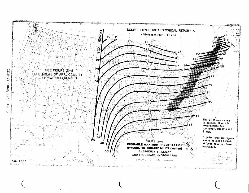
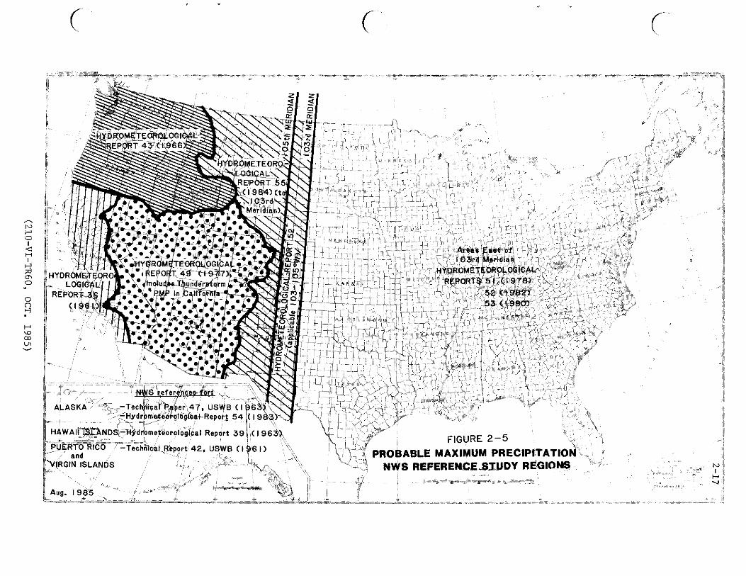
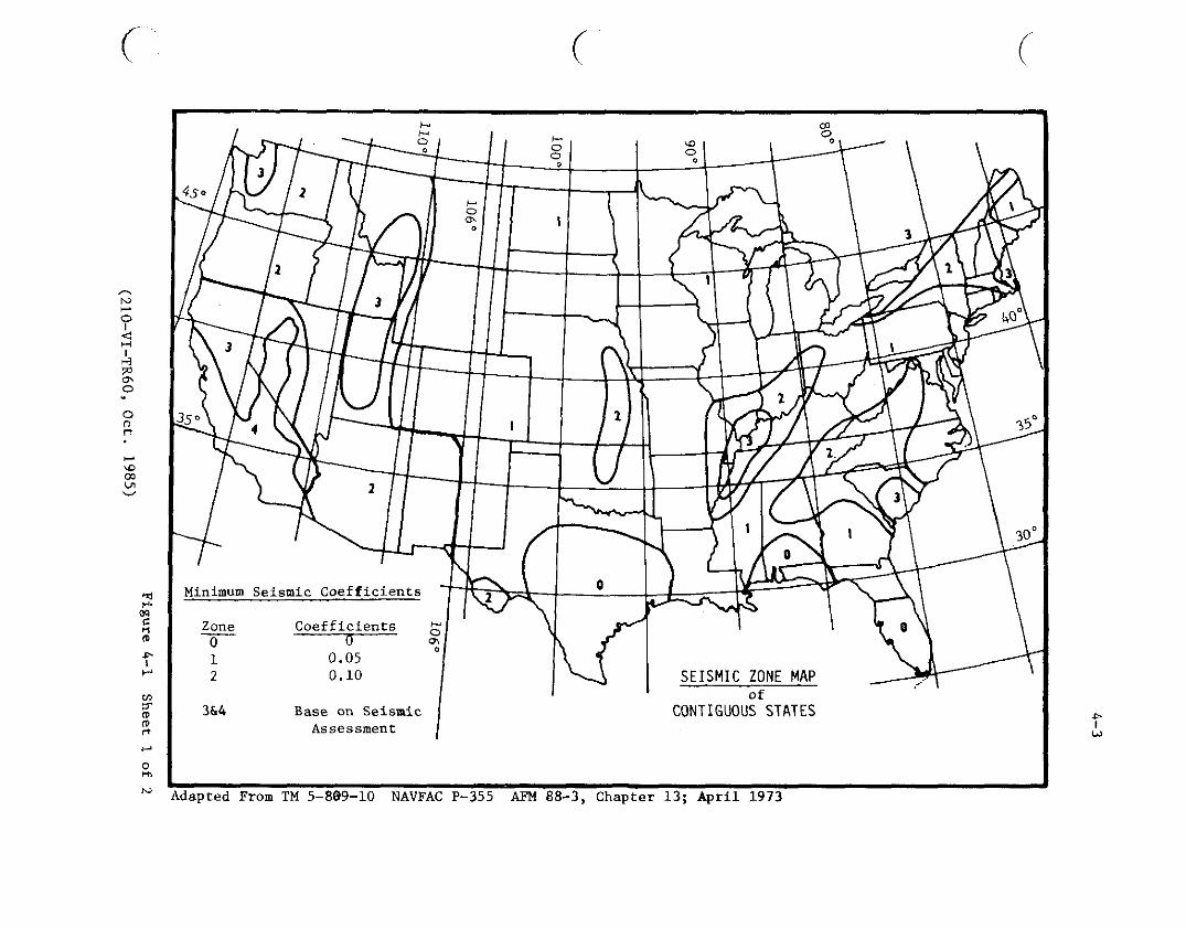
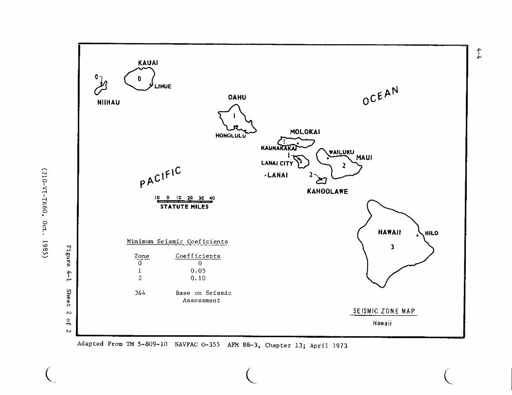
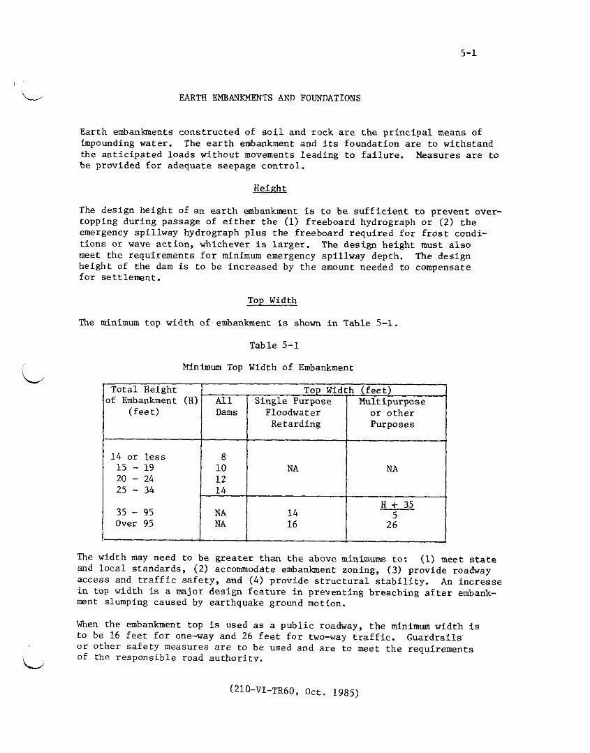
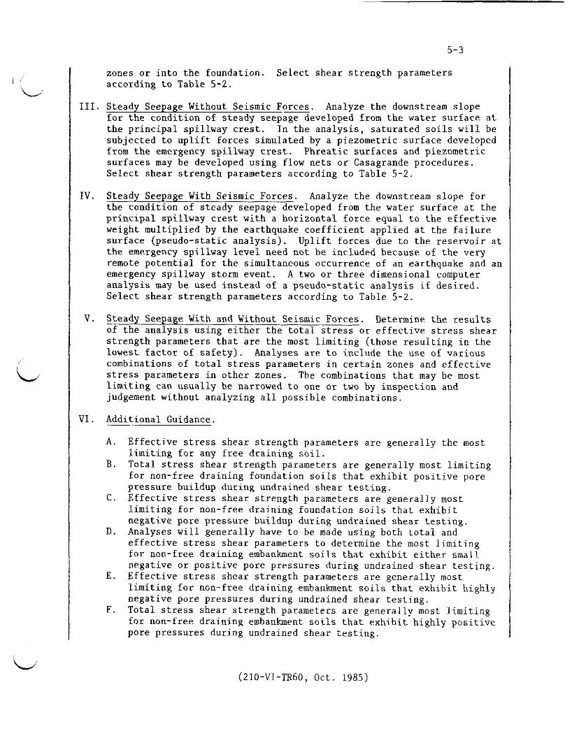
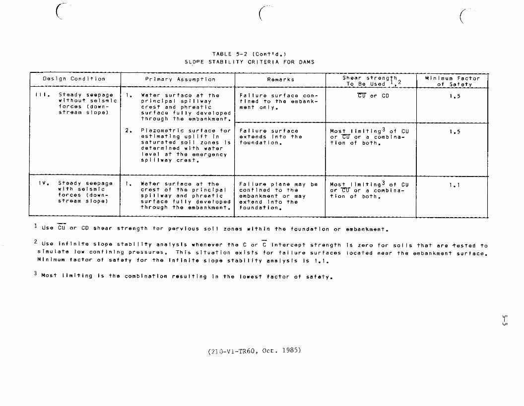