Embed Size (px)
Citation preview

0
Karamoja Productive Asset Program (KPAP)
Small Earth Dam Technical Assessment Report
Jack T. Chow, ACF Water Harvesting Consultant.

1
Contents
SUMMARY:................................................................................................................................................... 2
INTRODUCTION: ......................................................................................................................................... 4
Basic earth dam siting, design, and construction considerations. ....................................................... 4
Dam site soil specific requirement: .......................................................................................................... 4
Dam site catchment selection ................................................................................................................... 7
SMALL EARTH DAM DESIGN: ................................................................................................................. 10
CONSTRUCTION: ...................................................................................................................................... 12
LIMITATIONS IN IMPLEMENTING KPAP DAMS ..................................................................................... 14
PREDICTION OF WATER STORAGE LOSS: ........................................................................................... 15
OVERLOOKED TECHNICAL AND CONSTRUCTIONAL ASPECTS IN KPAP DAMS ........................... 16
Evaporation: .............................................................................................................................................. 16
Seepage looses: ........................................................................................................................................ 17
Dam embankment not following proper contour: ................................................................................. 18
Physical order of excavation lots: ........................................................................................................... 19
Shape of a chaco dam inlet on hillside dams: ....................................................................................... 19
IMPORTANCE OF EDUCATING COMMUNITIES BY BUILDING A MINI-MODEL EARTH DAM ........... 20
Upstream and downstream impact ......................................................................................................... 20
WORK NORM, MONITORING, AND FOLLOW-UP .................................................................................. 21
DAM PROJECTS TECHNICAL INFO AND SPECIFIC RECOMMENDATIONS ....................................... 22

2
Summary: A technical evaluation of small earth dams in Karamoja Productive Assets Programme (KPAP)
was conducted in a 3 week period from Aug. 15 to Sept. 9, 2010 in the Karamoja region of
Northeast Uganda. A total of 26 dams at varying stages of completion were visited. A general
observation which applies to all dams was that very few were built with much forethought to the
fundamental technical and siting criteria essential for a properly functioning earth dam. It was an
extraordinarily fortunate scenario that a majority of the dams were able to hold water, albeit with
significant rainfalls both before and throughout the duration of the field evaluation period.
There were frequent observed instances of communities wanting to build a longer and wider
reservoir. This was understandable as a visually bigger reservoir area gives the impression of
storing more water (at the expense of greatly increasing evaporative loss of water), in contrast
to a deeper but visually smaller reservoir of the same volume which minimizes evaporative loss.
This psychological bias was further reinforced by the division of reservoir excavation lots in 1m3
portions which results in many reservoirs being exactly 1m deep and extending only in the
horizontal direction due to easy organization of labor.
The poor construction quality of a majority of the embankments were made less apparent and
critical by the fact that most of the water is stored below the ground level in excavated
reservoirs. However, once water level reaches the constructed embankments above ground
level, seepage and erosion may occur.
Conventionally earth dams are constructed during dry season, but in Karamoja the lack of large
quantities of water needed for dampening soil for proper compaction of embankment means
that construction will need to be carried out at the start of wet season, ideally finishing as quickly
as possible to start immediately storing water for the rest of the wet season. It is essential to
have diverting channels or earth bunds to divert water away from the partially excavated
reservoir area during construction to avoid flooding delays. Constructions of many dams were
delayed due to water flowing into reservoirs before completion. For many dams, small sections
of embankments had to be temporarily removed to drain water away in order to continue
excavation work. This presents a potential weak spot on the embankment in terms of structural
homogeneity and seepage.
Local knowledge of both the catchment outflow and merging gullies on gentle sloping hillside
proved to be invaluable in the likelihood of dam reservoirs being filled up with water. The lack of
which usually results in reservoirs merely functioning as rain catchment basins where hardly any
water flows in from external areas.
Without the availability of catchment outflow data and coupled with highly erratic rain events, the
dams in Karamoja will have to be monitored and modified throughout its operational lifespan,
especially the first few years. This includes deepening the reservoir, adding/modifying spillway
and embankment, creating water diverting channels/earth bunds to increase inflow to the
reservoir.
Culturally this is likely to be an invaluable experience for the dam project communities in
strengthening cooperation, team organization, and sharing common goals. The numerous
technical imperfections, mistakes may serve as excellent lessons. After all, we all learn more
from our mistakes.

3
The most important lesson to be learned during this evaluation, to ensure a well-functioning
small earth dam, is having the combination of good local knowledge of the catchment area -
with clear signs of water outflow; and field staff who have the technical skills and fundamental
knowledge of basic earthen dam structures to educate the community and to be always present
during construction.

4
Introduction:
Basic earth dam siting, design, and construction considerations Small earth dams are water storage dams with capacities up to about 10000 cubic meters and
having embankments up to a height of about 5 meters. [Ref 1] Small earth dams can be built
manually, using animal draught, a farm tractor, a crawler or bulldozer.
Conventional dam design follows a sequence of steps starting with the calculation of daily water
use requirement, collecting monthly rainfall distribution data, estimating catchment area water
outflow, estimating evaporation and seepage losses based on soil and laboratory tests,
calculating required dam reservoir storage volume, and finally determining dimensions and
height of embankment based on selected dam site topography.
In the KPAP context small earth dams are part of a food for work program using inexperienced
manual labor with basic tools such as shovel, hoe, wheel barrow, plastic bucket, broken jerry
can, and field made manual compactor. It is worth noting that in the unavailability of design data
and basic earthworks construction tools such as levels and measuring tape, many conventional
earth dam technical requirements will be partially simplified or ignored. Since all of the KPAP
dams are relatively small hillside dams situated on gentle (<5%) slopes with small gullies
feeding water to the reservoir, the dams will most likely function in a safe manner despite
ignoring some of the conventional technical requirements more applicable to larger dams.
In the KPAP context, the quality of construction plays a bigger role than the conventional
technical specifications. For safety margin and technical reasons small earth dams in Karamoja
should be limited to storage capacities of no more than 5000 cubic meters and a height of 4
meters.
The first step in building a dam is to identify the best location. There will be many factors
including cultural, political, and technical that affect this. Ultimately it is up to the judgment of the
community and a knowledgeable construction supervisor to balance all the trade-offs involved in
the site selection. The dam siting discussions in this report will be strictly focused on the most
elementary and fundamental requirements necessary for a dam reservoir to stock water in the
Karamoja context.
Dam site soil specific requirement: We are primarily in interested in two basic soil features when we are building an earth dam; soil
permeability and soil strength. Soil permeability predicts the seepage rate of water stored in a
dam reservoir, and soil strength indicates stability and strength of the dam embankment. The
properties that effect both permeability and strength are numerous and complex. But, they do
not have to be understood completely to perform some simple tests to determine if a soil is
suitable for building dams.
There are many different ways to classify soil. The method presented here is a simplification of
the Unified Soil Classification System (USCS). It has been reduced to the point that the tests
can be performed in the field with little difficulty but the results are still useful. It is worth noting
that the USCS is different from the methods agriculturists and soil scientists use to classify soils.

5
Soil can be broken down in to two basic categories: organic soils (such as peat) and non-
organic soils (sand, gravel, silt, and clay). Organic soils are formed from rotting and
decomposing plant and animal matter and are characterized by high compressibility, dark color,
and occasionally an organic smell. Because of their instable nature and extreme variability it is
considered to be completely useless for foundations, embankments, and other forms or
structures of engineering. Soils with small amounts of organic matter don’t have to be
discarded completely, but the amount should be as little as possible.
Non-organic soils are soils that have been produced through erosion and other geologic
processes. The four basic types are: clay, silt, sand, and gravel. The differences between
these types of soils are the size of the grains. Clay and silt also have chemical and shape
properties that separate them, but since neither can be seen with the naked eye so they must
be differentiated based on feel and other factors. Since almost all soils contain a combination of
these grain sizes, soils can be classified based on how much of each type is present.
Table 1: Description of basic non-organic soil grains
It is possible to get a rough idea of the distribution of the grain sizes using a straight glass jar.
Take a narrow glass jar with a tight lid. Fill it half way up with a representative soil sample
(gravel is easy to spot and can be removed and noted ahead of time). Fill to the top with water
and then shake vigorously to put all particles into solution. Let sit for 24 hours or until the water
is clear. The soil will sink to the bottom with the largest grains first. It is now possible to make a
rough estimate of the percentages of each grain type and by measuring the height of each soil
grain with respect to the total soil height as shown in Figure 2.

6
.
Figure 2: Example of estimating soil grain type.
Soils with large amounts of clay are naturally impervious. To be suitable for the impervious
embankment of the dam the soil will need at least 25-55% clay particles (USCS classification).
A quick test for clay is to cut a lump of soil with a knife. If there is a bit of a shine to the soil it
has a fair amount of clay in it. Also, a good clay soil will be able to roll into a “snake” about 1.5
mm thick and 40 mm long without breaking. Some experimenting with different amounts of
water may be required. The wide range of clay content acceptable for dam embankment is due
to the differing soil structure (how each grain type is arranged and attached to one another). A
soil with lower clay content can be more impervious than a soil with higher clay content due to
structural differences.
Once a potential suitable soil is found, a final check will be to perform the infiltration or
permeability test, which can reveal the water retention abilities of a particular combination of soil
type and structure. An onsite infiltration test is usually performed in conventional soil testing,
using concentric metal rings of different standardized dimensions as shown in Figure 3.
In dry soil, water infiltrates rapidly. This is called the initial infiltration rate. As more water
replaces the air in the pores, the water from the soil surface infiltrates more slowly and
eventually reaches a steady rate (when soil is completely water saturated). This is called the
basic infiltration rate. We are interested in the basic infiltration rate for an earth dam reservoir.
Figure 3: Infiltration test ring

7
The infiltration test is usually carried out in 1 hour interval with the results expressed in water
level drop in mm per hour (mm/hr). To be suitable for an earth dam to store water we like to see
less than 1-2mm/hour of infiltration rate at the dam reservoir site. In the KPAP context, there are
no standardized metal testing rings available for onsite testing. Instead, a rough approximation
of the test is to simply dig a hole about 20-30cm diameter and 20-30cm deep, filing the test hole
with water making sure the soil is completely saturated, inserting a ruler, starting a timer (mobile
phone) for 10 minutes and recording the starting and ending marks on the ruler to calculate the
infiltration rate (see Figure 4). It is important to note that this test needs to be done at the bottom
depth of the potential reservoir. This means that if the reservoir will be 3 meters deep, a working
space/pit that is 3 meters deep at the potential dam reservoir site will have to be dug first, then
the infiltration test hole can be dug at the bottom of the working pit. From field observations in
Karamoja the dams can hold water with a tested infiltration rate as high as 4-5mm per hour.
This is due to silt being washed into a new earthen reservoir, clogging up the pores in the soil,
thus helping with the retention of water.
Figure 4: Rough approximation of infiltration test
Dam site catchment selection In general a dam should have the potential to fill completely with water runoff (most normal-
rainfall years) or store sufficient water between runoff events. In Karamoja the purpose of a
small earth dam is to store as much water as possible to last throughout the duration of a dry
season, or at least minimize the effects of drought. Obviously, dam catchment area
characteristics become critical in this scenario. We want to ensure that there is actually decent

8
amount of water flowing into a dam reservoir. In the absence of reliable local rain data and
catchment area estimation, local knowledge becomes invaluable in terms of ensuring there will
be water flowing out from the catchment area into the dam reservoir. For any potential dam
catchment look for obvious signs of water runoff.
In cases where the rainfall data and catchment area are known, the water outflow (technically
termed: catchment yield) can be approximated by:
Catchment yield:
Rr = 10% of the annual average rainfall in mm
Catchment area A in km^2
Catchment yield Y (m^3) = Rr * A * 1000
The size of the dam reservoir would be built relative to the catchment yield. Dam catchment can
include gentle sloping hillsides, small converging gullies, seasonal gullies, small creeks, or
diverting water channels. Figure 5, 6 and 7 shows examples of dam catchment.
Figure 5: Ideal gentle slope hillside dam catchment

9
Figure 6: Ideal gully leading to a dam reservoir
Figure 7: Chaco dam inlet. Silt traps will have to be implemented for this inlet to prevent
excessive siltation of the reservoir.

10
Small earth dam design: A typical design of a small earth-fill dam is shown in Figure 8. For stability, the upstream slope
must be a minimum of 3:1. Erosion protection is required to protect the dam from wave action.
This protection can be achieved with a combination of smaller and larger rocks (or other suitable
material).The downstream slope requires a minimum 2:1 slope, seeded with native grasses to
prevent surface erosion. The top or crest of the dam should be a minimum of 2m feet wide for a
stable embankment structure. The crest elevation should be a minimum of 0.5m above the Full
Supply Level (FSL) of the reservoir. The dam should be fenced to prevent livestock traffic, as
this traffic can be a major cause of slope and crest degradation. A textbook perfect dam
embankment structure would look like the one in Figure 9. The crest width and the slope of
embankments can be designed according the guidelines in Table 2 and 3.
Figure 8: Typical earth dam layout. (Ignore riparian pipe for our purpose)
Table 2: Crest width based on different dam embankment height
Table 3: Embankment slope based on soil type

11
Figure 9: Textbook perfect dam embankment
Spillway:
Spillway is a critical design feature of any dam. Spillway prevents overtopping of the dam and
serious erosion during peak water runoff. Spillways in KPAP dams should only handle water
flow once in a while during extremely heavy downpour events. They should not be handling
water flow on a continuous basis. If this happens, the dam reservoir needs to be built bigger
(deeper) to handle the normal catchment outflow. To prevent erosion of the spillway itself, riprap
(a collection of loose stones) can be used. For most U-shaped hillside or chaco dams in KPAP
(see Figure 10), spillways would be located at the tips of the U. Rocks and/or clay bricks would
be piled on the edge of the embankment, compacted into the soil. The idea here is to prevent
erosion of the U-tip edge and the downstream side of the embankment during overflow events.
The height of the spillway will determine the full-supply-level (FSL) of the dam reservoir, which
needs to be at least 0.5m from the top of the dam crest as previously indicated in Figure 8.

12
Figure 10: Hillside dam sectional views showing spillway rock piles. Adapted from Water from
Small Dams, 2006.
Construction: In the Karamoja context we will strictly be working with homogeneous-fill earth dams.
Diaphragm and zone type earth dams will not be discussed as they require careful technical
supervision and semi-skilled labor. Homogeneous-fill type dam means that all of the
embankment fill material has the same soil property. The fill materials should preferably be
taken from the reservoir area or a borrow pit close by. The following materials should be
avoided: organic material— including topsoil — decomposing material, material with high mica
content, calcite clays, fine silts, schist’s and shale’s, cracking clays, and sodic soils. Avoid
material with roots or stones. Normally dams are constructed during the dry season. In
Karamoja because of the unavailability of large quantities of water necessary for dampening the
soil for optimum compaction, the dam construction will need to be carried out at the start of wet

13
season, ideally finishing in a month to start immediately storing water for the duration of the rest
of the wet season. It is essential to have diverting channels or earth bunds to divert water away
from the partially excavated reservoir area during construction to avoid flooding delays.
At the foundation of the embankment topsoil will need to be stripped (note bottom of Figure 8)
because it contains organic matter (such as roots) which prevents proper compaction and may
provide seepage routes (piping) once the organic matter has decayed.
It doesn’t matter how good the dam design and siting is if the construction is subpar. This is
especially true in the Karamoja context where constant technical supervision and skilled labor is
usually not available. Ideally the dam will be built like a layer cake, one piece right on top of
another. Once the soil is placed there is no sneaking back to work on something that was
forgotten. Before any construction is started, thoroughly review the plans and make a list of
what must be placed first, second, etc. Digging up soil and attempting to re-compact it will
cause weak spots in the embankment.
The dam should be built roughly 10% taller than designed. Soil will settle and consolidate over
time. The 10% allowance will help assure that it will still be the size it was designed for years in
the future. 10% is a rough and safe estimate for embankment settlement. For un-compacted
soil the dam will settle by 30% in height.
In order for the soil to act as predicted, it must be fully compacted. Compaction is the process
of removing the voids from the soil and making it as dense as possible. The key to good
compaction is; small lifts, good energy, and the right amount of water. Placing the soil in layers
that are too big is a problem that plagues even professionals in developed countries. Even
heavy equipment can’t make up for soil layers that are too thick. For hand compaction methods
it is recommended to compact soil after every 20cm layer that has been laid. The greatest
challenge to achieving the best compaction possible is getting the soil damp enough to pack,
but not too wet. The optimum moisture content depends on soil type as shown in Table 4. It is
very time consuming to ensure proper compaction, and it is a difficult concept for unskilled labor
to understand. In earth dam construction the consequences of poorly compacted soil are far
worse than falling behind schedule or other non-conforming technical specification. A simple
test to evaluate proper compaction is to place the edge of the heel of a hard-soled boot on the
fill and push down hard with all your weight. If only a mark is left, compaction is satisfactory. If
the heel sinks in, compaction is poor.
Table 4: Optimum moisture content for compaction

14
Limitations in implementing KPAP dams There are important limitations and challenges in implementing small earth dams for the
purpose of stocking water in any drought prone semi-arid region. The situation is made worse
when very little data are readily available to aid in the design or the understanding of the critical
limiting factors. The lack of basic elementary technical knowledge of the unskilled labor and
social political issues of community mobilization and organizing labor further complicates what
can realistically be constructed in the Karamoja context.
One of the critical dam design criteria; long term, reliable, measured local rainfall data was hard
to come by in Karamoja. However, recent advances in climatology combining satellite imagining
and limited rain gauge network enable the creation of rainfall data shown in Figure 10. (Famine
Early Warning System – Network)
Figure 10: NE Karamoja regional rainfall distribution data, adapted from USAID Karamoja Food
Security assessment report 2010. Annual mean (12 yr Avg)= 698mm/yr with 219mm std dev.
Another key design criteria; the evaporation data was also not easily available. Two references
in the Africa climatology literature were consulted [ref 2,3]. Potential evaporation (PET) for the
NE Karamoja region where all the KPAP dams were built is estimated to be 1800-2200
mm/year, with roughly an even distribution of 5-7mm every day.
Based on the two important pieces of data above, the critical limiting factor in implementing a
water stocking dam in KPAP becomes that of keeping the water from evaporating away. In

15
general all earth dams will suffer from a number of constraints common to Karamoja’s semi-arid
environment. These include:
High evaporation rates leading to significant losses from any water stored in open
reservoirs.
Low and erratic rainfall and prolonged droughts over several years of below average
rainfall may lead to empty reservoirs.
Siltation due to large amounts of sediment washed into reservoirs during severe storms,
especially at the end of the dry season, which also makes the water turbid. Siltation can be
avoided by trapping inflowing silt in silt traps and utilizing it for fertilizing garden plots.
Contamination of water in open reservoirs can be caused by livestock entering
reservoirs resulting in poor water quality. Clean water for domestic use can be drawn from a
hand-dug well sunk in the immediate downstream slope area with seepage from the dam
reservoir. (Assuming percolation rate isn’t too high and water spend 20+ days seeping through
the soil to the well location.)
The risk of small children and livestock falling into reservoirs. Small water reservoirs
should therefore always be fenced. Ideally animals and people can only enter from the shallow
sloping or stable rock/clay brick steps leading to the reservoir.
The use of highly contaminated stagnant surface water stored in the dam for domestic
purposes during severe drought when no other water sources are available.
Dam reservoir becomes potential mosquito breeding ground. Critical health concerns if
dam situated too close (<100m) to manyatta settlements.
Prediction of water storage loss: The rainfall distribution in Figure 10 coupled with the evaporation data can be used to estimate
the water storage loss in open reservoirs in Karamoja. According to Figure 10, there is very little
chance for the months starting mid-November until April to have any useful rainwater runoff into
the dam reservoirs, and at the same time daily evaporation rate exceeds the precipitation rate.
The net vertical water level drop rate would be in the range of 4-6mm a day. Assuming a net
5mm drop a day, and 135 days from Mid-November to April, a total drop of 675mm will occur
from evaporation alone. Adding in 25% of total drop from seepage losses, we will lose a total of
roughly 850mm of water level during those drought months. It is assumed that the moderate
duration rain events plus occasionally high intensity downpours starting from April and lasting
until September would be enough to fill most properly sited dam reservoirs. The reservoirs will
not be filled at the start of mid-November if the above assumed rain events do not occur. One
reference cited any rain event less than 12mm/day in the Karamoja region is unlikely to produce
meaningful runoff. This rough estimate of 850mm water loss during drought months highlights
the importance of making the dam reservoir surface area smaller along with other measures to
minimize evaporative losses. There is more to be discussed in the next section.

16
Overlooked technical and constructional aspects in KPAP dams Evaporation: Without a clear, irrefutable understanding on the effects and the mechanics of evaporation,
KPAP beneficiary communities were all building dam reservoirs which are significantly longer
and wider than it is deep (Figure 12). This was completely understandable as a visually bigger
reservoir surface area gives the impression of storing more water. A larger surface area will
greatly increase evaporative loss of water. No one can be expected to build a deeper but
visually smaller reservoir of the same volume (which minimizes evaporative loss) when they do
not fully understand how much water will be lost from evaporation.
A useful rule of thumb is that about 50% of the water in a reservoir is lost each year to
evaporation, assuming that the reservoir is not build like an evaporation pond (long, wide, and
shallow), in which case ALL of the water will be lost. Unfortunately many of the KPAP dam
reservoirs were built like evaporation ponds, as a result some modifications will be required to
enable the dams to prolong the storage of water.
Figure 12: Dam reservoir built like an evaporation pond.
Recommended actions for dams built like evaporation ponds include:
Halt all horizontal direction excavations and continuing excavation only in the vertical
direction to make the reservoir deeper. This means disregarding the size of the perimeter area
of the currently finished dam embankment.
One way to reduce evaporation and conserve water towards the end of the dry season is
to deepen one end of the dam reservoir. As the pond dries out, the remaining water will
accumulate in the deeper section and minimize the area of water exposed to evaporation. For
17
many KAPAP dam reservoirs, this will be working on deepening just the ½ or the 1/3 of the
currently planned reservoir area.
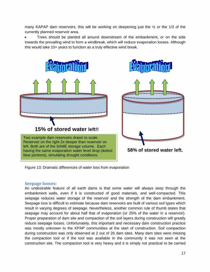
Trees should be planted all around downstream of the embankment, or on the side
towards the prevailing wind to form a windbreak, which will reduce evaporation losses. Although
this would take 10+ years to function as a truly effective wind break.
Figure 13: Dramatic differences of water loss from evaporation
Seepage looses: An undesirable feature of all earth dams is that some water will always seep through the
embankment walls, even if it is constructed of good materials, and well-compacted. This
seepage reduces water storage of the reservoir and the strength of the dam embankment.
Seepage loss is difficult to estimate because dam reservoirs are built of various soil types which
result in varying degrees of seepage. Nevertheless, another common rule of thumb states that
seepage may account for about half that of evaporation (or 25% of the water in a reservoir).
Proper preparation of dam site and compaction of the soil layers during construction will greatly
reduce seepage losses. Unfortunately, this important and necessary dam construction practice
was mostly unknown to the KPAP communities at the start of construction. Soil compaction
during construction was only observed at 2 out of 26 dam sites. Many dam sites were missing
the compaction tool or if the tool was available in the community it was not seen at the
construction site. The compaction tool is very heavy and it is simply not practical to be carried
15% of stored water left!!
58% of stored water left.
Two example dam reservoirs drawn to scale. Reservoir on the right 2x deeper than reservoir on left. Both are of the SAME storage volume. Each having the same evaporation water level drop (dotted blue portions), simulating drought conditions.

18
back and forth between the dam construction sites and the community. However, there might
be theft concerns if the tool was left at the construction site. This was a difficult issue to resolve.
For most KPAP dams the poor quality construction of the embankments were made less
apparent and critical by the fact that a majority of water is stored below the ground level in the
excavated reservoirs. Very few dams had water levels extending over the ground level above to
the embankments. For the few dams where water level has risen to the embankments, various
degrees of seepage can be observed. For serious seepage problems at isolated spots of the
embankment, there are two recommended remedies:
1. Opening up and digging into the downstream slope of the seepage spot of the
embankment, look for roots, large rocks, and other potentially rotting organic material, remove
them, and apply layers of clayey soil, and lastly compact well. This is sort of a band-aid solution
and needs to be done very carefully when opening up and digging into the embankment since
water level will be above the spot where the digging needs to take place. The embankment wall
at the spot could potentially collapse and release all of the water from weakened wall structure.
2. Waiting until the water level recedes below the ground level. Then apply the above
steps. In this case there will be no risk of wall collapsing since there won’t be water on the
upstream side of the embankment.
For seepage problem of the entire dam reservoir due to improper site selection, a potential fix is
to use plastic sheeting (1 mm polypropylene or 1.5 mm HDPE) blanket covering the entire
wetted reservoir surface area. This involves digging an additional 0.5m soil depth on all wetted
surfaces of the reservoir, laying down the plastic sheeting overlapping each sheet by at least
0.15m, and applying well compacted 0.5m soil above the plastic sheets to hold them in place. A
material cost of roughly $3000 UGX per m2 plastic sheeting can be used to calculate the total
cost for the blanket. For a typical 30m x 30m x 4m rectangular dimensioned excavated
reservoir, the wetted surface (not including embankment) is 2280m2 and the cost of the
impermeable plastic blanket would be $6,840,000 UGX. It is up to the KPAP project managers
to decide if the cost benefits are worth the investment. This typical example demonstrates that it
may be more cost effective to build a new dam at a new location than to patch up an existing
dam site which was poorly chosen.
Dam embankment not following proper contour: In many observed instances the bottom-section U embankment wall is build lower than the U
sides or the tips (see Figure 11). It does not make sense for that part of the wall to be lower than
the sides and the spillway as this means that the dam wall will be overtopped in cases of
overflow. The positioning of some of the embankments is not ideal as they are in the way of the
ground slope and blocking runoff water from entering the reservoir. Some of this oversight can
be attributed to the lack of an onsite leveling tool or the lack of the understanding of the need to
absolutely avoid overtopping earth dam walls. A basic field-made level can be made from a half-
filled plastic water bottle tied to a piece of long-straight stick about 1m long. The half-filled water
level in the bottle is used to indicate the horizontal ‘levelness’ of the stick. This simple tool will
be able to correct most eye-sighting errors when used during construction.

19
Figure 11: Example of dam embankment not following proper contour.
Physical order of excavation lots: There were many observed instances of the edges of the dam reservoirs being excavated first
instead of the center part of the reservoir. This makes it easy to identify the size and the location
of the embankments but that wouldn’t have been a concern in the first place if the location had
been properly measured and marked. This also wouldn’t have been an issue if a suitable
number of ‘construction work pathways’ for transporting excavated soil are reserved and
designated. But the situation was that the majority of the reservoir perimeter excavation lots
were dug, leaving a huge portion of the middle part of the reservoir to be excavated, but with a
very narrow pathway where all workers must now use to transport soil out to the embankments.
This became an extreme case of construction inefficiency in terms of queuing and unnecessary
back and forth traffic. In some cases people were simply picking up the dirt from excavation lots
with their hands, and throwing it over the completed excavation lots that’s now blocking their
access to the outside of the embankments. It is recommended to carefully plan and
communicate future reservoir excavations to minimize inefficient labor use and bottlenecking
conditions.
Shape of a chaco dam inlet on hillside dams: Many hillside dams had chaco dam style C-shaped inlets instead of a U-shaped inlet. For chaco
dams the C-shape inlet is necessary because of the narrow gully inlet where it’s the only source
of water entering the reservoir. For a hillside dam inlet it is wrong to use the C-shaped inlet and

20
works against the ideal situation where we want to catch as much water as we can from the
wide, flat slope typical for a hillside dam catchment.
Importance of educating communities by building a mini-model earth dam The author had several opportunities to interact with the communities during the construction.
There were a few instances where the community feels strongly about the way they would like
their dam to be built and would not readily accept some of the technical recommendations made
by the author. This was a revealing experience and coupled with many other overlooked dam
constructional aspects underscored the need to educate the communities before implementing
a dam project. The author had excellent feedback from conducting a dam construction
workshop where a 50cm x 40 cm long mini hillside earth dam complete with spillway, proper
embankment slopes and scaled dimensions were used to demonstrate various technical
operating criteria of an earth dam. Water was poured into the mini-catchment and into the model
dam, showing what happens when the dam overflows and the importance of proper spillway
design/location/construction. Every aspect of the technical specification and construction can be
demonstrated with the mini-model dam. Such a model can be constructed at potential dam sites
in less than 30 minutes by field staff. This presents the communities a live, visual presentation
of what a finished dam should look like and how it should operate. It is the author’s belief that
this kind of onsite training will have the utmost positive impact and lasting effect, more so than
any printed field guides or manuals.
Upstream and downstream impact Before constructing a dam, the environmental impact must be evaluated. Small earth dams do
not have a major impact, except if many small dams are constructed in the same catchment, in
which case their combined effect could be significant. This has not been observed in KPAP
dams as none are sharing the same catchment area. In terms of downstream impact it is critical
for any earth dam design to take into account the consequences in case of a catastrophic dam
failure. None of the KPAP small earth dams are built big enough or situated in a location where
possible loss of life could occur should the dam fail. Most KPAP dams are located on
wide/gentle sloping hillside, with most of the water stored under ground in excavated reservoirs.
There is no upstream impact and the only downstream impact is the slightly wetted soil
downstream of the embankment from the water seepage. We would actually like to take
advantage of the wetted soil by planting tree lots or orchards or other crops that likes to grow in
a high moisture content soil. There is only one KPAP dam (Toroi West) utilizing a seasonal gully
way/small creek. In this case the upstream impact is the higher than normal flood water line
along the upstream gully and the downstream impact is the dryer gully bed due to most of the
water trapped in the reservoir and in the upstream gully way. In cases of dam failure there will
be slight amounts of rushing flood water into the otherwise dry downstream gully way, flood
water should be no more than a meter deep. There are no communities situated close to the
upstream or the downstream part of this isolated gully way which drains into a nearby bigger

21
water way and eventually into a river. There is minimum ecological impact for this chaco dam
location.
Work norm, monitoring, and follow-up A work norm was implemented for KPAP dam construction. 1m3 of earthworks is assigned to
each person per 5 hour work day, with 8 total work days per month. 1m3 is what each person
are expected to complete in one work day. This work norm looks to be very reasonable.
Assuming 100 people were to build a 30m x 30m x 3m reservoir for a hillside dam. We have
2700m3 of excavation needed plus additional earth bunds/channels for water diversion during
construction, and soil from borrow pits nearby for properly compacted embankments. Factor in
20% of extra soil volume required in addition to the actual excavation, we have a total of
3240m3 of earthworks to be divided among 100 people. Each person will be responsible for
roughly 32m3 of earthworks, and if we use 8 total work days per month, the total dam
construction time will be exactly 4 month. If there were 200 people working on the same dam, it
does not mean that the construction time will be halved. There is a limit on how many people
can be in a 30m x 30m work area at the same time.
There is an un-intended negative consequence by assigning 1m3 per worker, when most
communities understood it as a 1m x 1m x 1m lot. When many workers are present (usually the
case), excavation work can only be expanded in the horizontal direction due to labor
organization and work space availability. This result in many dam reservoirs being exactly 1m
deep while being very long and wide (built like an evaporation pond). It is recommended that the
1m3 excavation lot be redefined as 0.5m wide by 1m long by 2m deep. Chipping away a 0.5m
section of soil is also more natural with regard to using the hoe. In addition, for any site with
more than 150 workers, it is recommended to split up the total number of workers into work
groups that work on different days to avoid overcrowding of the construction site. It is further
recommended to split up each work group into three sub-groups; one for excavation, one for
hauling soil, and another group dedicated to compacting soil, and all the groups would rotate
their work every 10-15 minutes or so. The rotation of work is important as manual excavating
and compacting work is incredibly physically demanding. It would not be unusual to have equal
duration work time and breaks due to the extreme physical demand.
There were some discussions and concerns as to whether a work-hour based or a result based
work norm would be more appropriate. This concern came up when some communities seem to
take much longer to complete their dams compared to other communities. Many dams were
seemingly behind schedule due to a variety of factors. It was difficult to establish a standardized
work-progress norm when every dam site has different soil and other environmental conditions.
On a sandier soil with lower clay content when the soil is slightly moist, it is relatively easy to
excavate a 1m3 area. Conversely, on a high clay content soil when completely dry, it becomes
more time consuming (by a factor of two or more) to excavate the same volume of soil. For
some dams the onsite inefficiencies and bottlenecking issue were seriously delaying the
construction progress. While others had flooding issues that also caused significant delays with
extra work needed.

22
In consideration of the vastly different situations at most dam sites, coupled with community
mobilization issues, monitoring of the work norm and construction progress becomes the
responsibility of the field staff or the construction supervisor. It is up to the judgment of the
onsite supervisors to determine whether a proper work norm has been followed and whether a
dam’s construction progress is satisfactory.
Without the availability of catchment outflow data and coupled with highly erratic rain events,
any newly constructed dams in Karamoja will have to be monitored and modified throughout its
operational lifespan, especially the first few years. This includes deepening the reservoir,
adding/modifying spillway and embankment, creating water diverting channels/earth bunds to
increase inflow to the reservoir. The success of the crucial future monitoring and maintenance
tasks will depend on the strength of the leadership of each dam project’s management
committees.
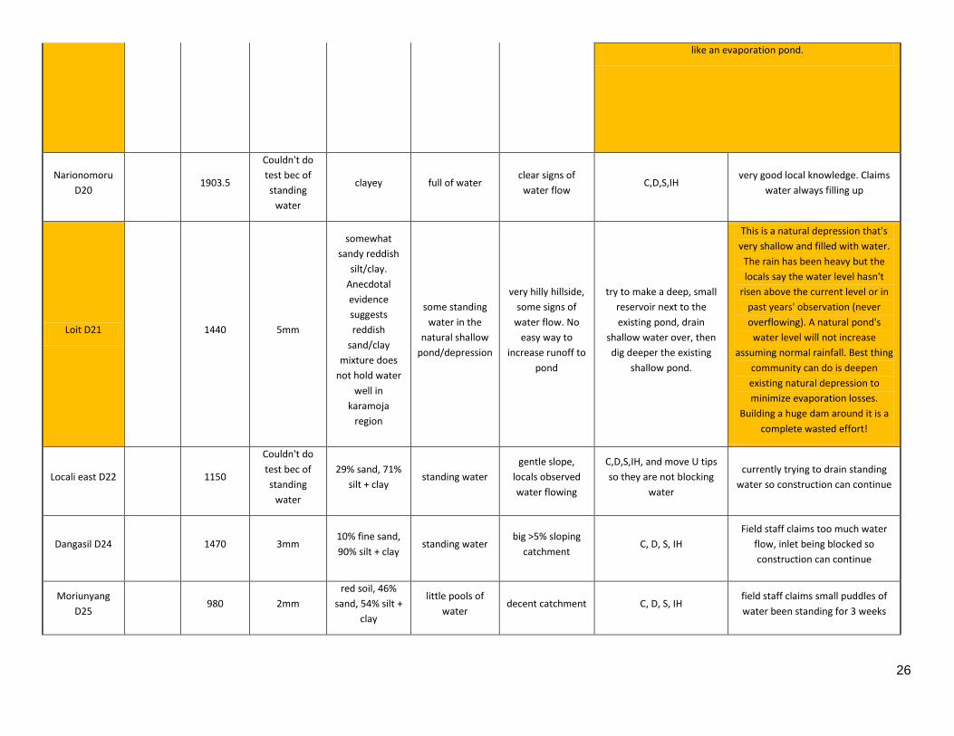
Dam projects technical info and specific recommendations A total of 26 dam project sites were visited by the author. Table in the following pages lists some
of the technical information and specific notes and recommendations for each dam project.

23
Dam project
Village workers
Reservoir
Volume
(m3)
Infiltration
(mm/10 min)
Soil
Composition
Holding water at
time of site
visit?
Catchment
area/inlet
Action (C=compact soil, D
= deepen reservoir,
S=spillway, IH=increase
wall height)
Comments and critical concern (if
any)
Reservoir 46 1800 1mm dark clay full of water natural gully inlet,
chaco dam style C, D, S, IH
currently trying to drain standing
water so construction can continue
Moruangisigiria 36 1000 2mm
dark clay sand,
hard to
determine ratio
yes plenty of water
flow signs
C, D, S, IH and move 1 tip
of U so it's not blocking
water from entering
there is a natural bank on one side
of the dam, advised to remove one
of the U legs and make natural bank
be part of dam.
Nalebeny D12 38 1250
Couldn't do
test bec of
standing
water
dark clay full of water
locals say plenty
of water flow
from the <3%
slope
C, D, IH and move both tip
of U so it's not blocking
water from entering
currently trying to drain standing
water so construction can continue
Lemugete 49 1000
Couldn't do
test bec of
standing
water
dark clay full of water
<2% slope, signs
of good water
flow
C, D, S, IH currently trying to drain standing
water so construction can continue
Natipem 45 600
Couldn't do
test bec of
standing
water
dark clay full of water natural gully inlet,
chaco dam style C, D, S, IH
currently trying to drain standing
water so construction can continue
Toroi Central 123 1287
>20mm,
second test
2mm (total
saturated soil)
fine sandy soil,
small amount
of clay
yes but a small
shallow area
only (after
recent big
rainfall)
decent sized
catchment, but
not much signs of
water flowing
Deepen reservoir when
there is no standing water.
This reservoir is made like an
evaporation pond…and the main
problem is that there are no signs
of water flowing in.

24
Toroi West 88 1144.53
>20mm,
couldn't do
second test
couldn't get
sample due to
full reservoir
yes, almost full
level
good natural gully
inlet, chaco dam
style
spillway needed nicely capturing all water flow from
a seasonal gully way.
Leleokot D23 154 1221 3mm sandy clay yes
rock catchment
from steep hillside
one significant
rock
compacting, spillway,
increase bank height
locals do a good job of compacting.
First observed instance of it.
Ligot 120 600 4mm reddish 50%
sandy soil few spots
catchment area
very wide
C, D, S, IH, and move U tips
so they don't block water
from entering
slight concern with infiltration rate,
worth a revisit to see if holding
water after recent heavy rain
Nariwose 181
1250 3mm 40% sand 60%
silt+clay few spots
good catchment,
with good water
flow
C, D, S, IH
recently overtopped by heavy
rainfall. Locals repairing washed
away dam wall
Nariwore 94
Kalapata 95 750 >20mm 82% sand tiny spots very steep foothill After revisits confirmed no water holding due to high sand
content. Unfortunately this dam is a wasted effort
Locherep 181 3150 1mm 30% silt + sand,
70% silt + clay
standing water
at the deeper
end
huge catchment
area
Move tips of U so they
aren't blocking water from
entering. Dig only half of
the reservoir deeper
standing water may prevent
construction progress, dam is way
too big. Built like evaporation basin.

25
Lochom 154 1250
Couldn't do
test bec of
standing
water
good clay
content, exact
clay % hard to
determine
yes, decent size
pool of standing
water
<5% slope, natural
grass silt trap,
signs of water
flowing
compacting, spillway,
increase bank height
standing water may prevent
construction progress
Longaro D3 3750 1mm 50% silt + clay,
50% sand
standing water
at isolated dug
outs
decent sized
catchment
current planned reservoir
far too large. Advised
digging only half of the un
dug planned area. Tip of U
maybe blocking water
from flowing in.
standing water in dugouts prevent
construction progress
Usake D10 300 10mm sandy soil no tiny, no signs of
water flowing
advised not to carry out further work due to wasted efforts.
Unsuitable site with sandy soil, tiny catchment, no signs of water
flow
Narube D11 1500 1mm clayey yes
decent with
standing water on
shallow
depressions
move tips of U so they
aren't blocking water from
entering. Also dig only half
of the reservoir deeper
Nariamaoi D12 648
Couldn't do
test bec of
standing
water
clayey full of water Good C, D, S, IH standing water may prevent
construction progress
Tulelo D14 800
Couldn't do
test bec of
standing
water
clayey full of water Good
C, D, S, IH and move 1 tip
of U so it's not blocking
water from entering
standing water may prevent
construction progress
Nariwose D18
(sidok) 1400
Couldn't do
test bec of
standing
water
clayey full of water good, signs of
water flow C, D, S, IH
currently trying to drain standing
water so construction can continue
Loroyo (in
Kaped) D19 3522.4
didn't have
water to do
test
sandy clay
no, signs of
water
evaporation
one water
diverting channel
Existing dam rehabilitation, advised to dig a 20m semi circle 1.5m
deeper within the current huge reservoir. Locals claim dam was
filled before. In process of digging a diversion ditch to catch water
runoff from road side channel. Locals has very strong opinion on
wanting a big dam, does not want to listen to consultant's advise
of making just a 3rd of the current reservoir deeper. This will be
26
like an evaporation pond.
Narionomoru
D20 1903.5
Couldn't do
test bec of
standing
water
clayey full of water clear signs of
water flow C,D,S,IH
very good local knowledge. Claims
water always filling up
Loit D21 1440 5mm
somewhat
sandy reddish
silt/clay.
Anecdotal
evidence
suggests
reddish
sand/clay
mixture does
not hold water
well in
karamoja
region
some standing
water in the
natural shallow
pond/depression
very hilly hillside,
some signs of
water flow. No
easy way to
increase runoff to
pond
try to make a deep, small
reservoir next to the
existing pond, drain
shallow water over, then
dig deeper the existing
shallow pond.
This is a natural depression that's
very shallow and filled with water.
The rain has been heavy but the
locals say the water level hasn't
risen above the current level or in
past years' observation (never
overflowing). A natural pond's
water level will not increase
assuming normal rainfall. Best thing
community can do is deepen
existing natural depression to
minimize evaporation losses.
Building a huge dam around it is a
complete wasted effort!
Locali east D22 1150
Couldn't do
test bec of
standing
water
29% sand, 71%
silt + clay standing water
gentle slope,
locals observed
water flowing
C,D,S,IH, and move U tips
so they are not blocking
water
currently trying to drain standing
water so construction can continue
Dangasil D24 1470 3mm 10% fine sand,
90% silt + clay standing water
big >5% sloping
catchment C, D, S, IH
Field staff claims too much water
flow, inlet being blocked so
construction can continue
Moriunyang
D25 980 2mm
red soil, 46%
sand, 54% silt +
clay
little pools of
water decent catchment C, D, S, IH
field staff claims small puddles of
water been standing for 3 weeks

27
Napangimoe
D26 1750
Couldn't do
test bec of
standing
water
41% sand, 59%
dark silt + clay standing water
gully way going
into reservoir C,D,S, IH
sinking ground near dam inlet is a
concern, field staff instructed on
moving dam wall and sloping
current eroded sinking ground to
minimize effects. One section of
dam visibly seeping, likely due to
piping of uneven material buried
under un-compacted embankment

28
References:
1. Erik Nissen-Petersen, Water From Small Dams, Danish international development
assistance (Danida), 2006.
2. Woodshed, T., Studies of Potential Evaporation in Kenya, Ministry of natural resources,
water development department, 1968.
3. Dagg, M., Woodshed, T., Evaporaion In Africa, Bulletin of the international association of
science hydrology, Vol XV, 1970.
4. Karamoja Region Food Security Assessment: Uganda, FEWS-Network, USAID, 2010.
5. Coles, N., Treatment of Leaking Dams, Australia department of agriculture farm note,
2003.