Embed Size (px)
Citation preview

ERD
C/G
SL T
R-0
9-2
6
Evaluation of Ultra High Molecular Weight (UHMW) Polyethylene Panels for Aircraft Arresting Systems
E. Ray Brown August 2009
Geo
tech
nic
al a
nd
Str
uct
ure
s La
bor
ator
y
Approved for public release; distribution is unlimited.

ERDC/GSL TR-09-26 August 2009
Evaluation of Ultra High Molecular Weight (UHMW) Polyethylene Panels for Aircraft Arresting Systems
E. Ray Brown
Geotechnical and Structures Laboratory U.S. Army Engineer Research and Development Center 3909 Halls Ferry Road Vicksburg, MS 39180-6199
Final report
Approved for public release; distribution is unlimited.
Prepared for Headquarters, Air Force Civil Engineer Support Agency 139 Barnes Avenue, Suite 1 Tyndall AFB, FL 32403-5319

ERDC/GSL TR-09-26 ii
Abstract: Ultra high molecular weight (UHMW) polyethylene panels for aircraft arresting systems have been used in the United States for approxi-mately 15 years to provide better resistance to erosion of the pavement surface under arresting cables. When concrete or asphalt is used directly under the cables, the pavement surface becomes heavily damaged during a short period of time, requiring that the damaged area be removed and patched.
A research project was awarded to the U.S. Army Engineer Research and Development Center by the Air Force Civil Engineer Support Agency at Tyndall Air Force Base to inspect a number of polyethylene panels throughout the United States and Europe and to recommend ways to improve performance of the panels and the pavement materials and joint sealants adjacent to the panels.
Generally, the UHMW panels have provided much-improved perform-ance, but some changes are needed to improve the overall performance. Several problems have occurred, including warping of the panels, loss of bond between the sealant and the panels, and damage to the adjacent pavement surface when traffic passes over the joint between the panels and the pavement.
Items that need improvement include reducing the amount of warping, improving the bond between the sealant and panels, and improving the performance of the asphalt and concrete mixtures adjacent to the panels.
DISCLAIMER: The contents of this report are not to be used for advertising, publication, or promotional purposes. Citation of trade names does not constitute an official endorsement or approval of the use of such commercial products. All product names and trademarks cited are the property of their respective owners. The findings of this report are not to be construed as an official Department of the Army position unless so designated by other authorized documents. DESTROY THIS REPORT WHEN NO LONGER NEEDED. DO NOT RETURN IT TO THE ORIGINATOR.
ERDC/GSL TR-09-26 iii
Contents Figures and Tables.................................................................................................................................iv
Preface..................................................................................................................................................viii
Summary.................................................................................................................................................ix
Unit Conversion Factors..................................................................................................................... xiii
1 Introduction..................................................................................................................................... 1 Background .............................................................................................................................. 1 Objective and scope................................................................................................................. 3
2 Research Approach........................................................................................................................ 4
3 Site Investigations and Discussions with Locals........................................................................ 5 Background on requirements for UHMW polyethylene panels ............................................. 5 Aviano Air Base, Italy ................................................................................................................ 7 Buckley Air Force Base, Colorado..........................................................................................13 Davis-Monthan AFB, Arizona..................................................................................................15 Eglin AFB, Florida ...................................................................................................................18 Eielson AFB, Alaska................................................................................................................19 Elmendorf AFB, Alaska...........................................................................................................22 Hill AFB, Utah..........................................................................................................................29 Holloman AFB, New Mexico ...................................................................................................33 RAF Lakenheath, England......................................................................................................40 Luke AFB, Arizona...................................................................................................................43 MacDill AFB, Florida ...............................................................................................................46 McChord AFB, Washington ....................................................................................................48 Selfridge ANGB, Michigan......................................................................................................50 Seymour Johnson AFB, North Carolina .................................................................................50 Shaw AFB, South Carolina .....................................................................................................52 Spangdahlem AFB, Germany.................................................................................................59 Tinker AFB, Oklahoma............................................................................................................63 Tyndall AFB, Florida ................................................................................................................66
4 Observations and Discussion......................................................................................................77
5 Conclusions and Recommendations .........................................................................................89
Report Documentation Page

ERDC/GSL TR-09-26 iv
Figures and Tables
Figures
Figure 1. Early cable damage to concrete pavement. ............................................................................ 1 Figure 2. Typical patch area underneath cable in concrete pavement................................................. 2 Figure 3. Use of steel plate at a Naval Base to protect pavement damage from cable. ..................... 2 Figure 4. UHMW polyethylene panels at Aviano AB. ............................................................................... 8 Figure 5. SMA mixture placed adjacent to concrete foundation for barrier panels at Aviano AB. ................................................................................................................................................... 9 Figure 6. No damage of the SMA and slight spalling of the concrete slab at Aviano AB. ................. 10 Figure 7. Sealant in good shape adjacent to panels at Aviano AB. Note lack of sealant in anchor bolt recess.................................................................................................................................... 10 Figure 8. Sealant in poor shape adjacent to panels at Aviano AB. .....................................................11 Figure 9. Some spalling of concrete adjacent to panels and at contraction joint at Aviano AB. .................................................................................................................................................11 Figure 10. Anchors for panels placed very close to contraction joint in concrete at Aviano AB. .................................................................................................................................................12 Figure 11. Overview of UHMW polyethylene panels at Buckley AFB...................................................13 Figure 12. Condition of sealant around UHMW polyethylene panels at Buckley AFB....................... 14 Figure 13. Joint between panels match joint in concrete for panels at Buckley AFB........................15 Figure 14. UHMW polyethylene panels at Davis-Monthan AFB within approximately 10 ft of change in pavement type.................................................................................................................... 16 Figure 15. Variable width of joints in polyethylene panels at Davis-Monthan AFB. ........................... 16 Figure 16. Condition of joint between concrete and polyethylene panel at Davis-Monthan AFB............................................................................................................................................ 17 Figure 17. Damage to polyethylene panel likely caused by cable beating on surface of panel at Davis-Monthan AFB...................................................................................................................18 Figure 18. Overview of UHMW polyethylene panels at Eglin AFB........................................................19 Figure 19. Overview of UHMW polyethylene panels at Eielson AFB showing concrete on both sides of the panels (south end of runway). ...................................................................................20 Figure 20. Loss of joint sealer between panels and concrete pavement (south end of runway) at Eielson AFB. ...........................................................................................................................20 Figure 21. Exposure of backer rod between panels and concrete pavement (south end of runway) at Eielson AFB. ........................................................................................................................... 21 Figure 22. Overview of UHMW polyethylene panels at Eielson AFB showing concrete on both sides of the panels (north end of runway)..................................................................................... 21 Figure 23. Typical spalling in concrete adjacent to panels at north end of runway at Eielson AFB...........................................................................................................................................22 Figure 24. Overview of UHMW polyethylene panels on Runway 34 at Elmendorf AFB.....................22 Figure 25. Some damage to the asphalt mixture adjacent to the concrete strip on Runway 34 at Elmendorf AFB. ................................................................................................................23

ERDC/GSL TR-09-26 v
Figure 26. Condition of joint sealant on Runway 34 at Elmendorf AFB.............................................. 24 Figure 27. Excessive sealant on the pavement surface on Runway 34 at Elmendorf AFB............... 24 Figure 28. Partially sealed anchors on Runway 34 at Elmendorf AFB. ..............................................25 Figure 29. Overview of panels on Runway 06 at Elmendorf AFB. .......................................................26 Figure 30. Minor surface wear of the pavement surface and rounding of the edges on Runway 06 at Elmendorf AFB. ................................................................................................................26 Figure 31. Sealant in reasonably good condition on Runway 06 at Elmendorf AFB. ........................ 27 Figure 32. Sealant in poor condition on Runway 06 at Elmendorf AFB. ............................................ 27 Figure 33. Overview of panels on Runway 24 at Elmendorf AFB. .......................................................28 Figure 34. Bump between asphalt pavement and concrete strip on Runway 24 at Elmendorf AFB..........................................................................................................................................29 Figure 35. Condition of sealant between the concrete and asphalt pavements was generally good on Runway 24 at Elmendorf AFB. .................................................................................30 Figure 36. Poor performance of sealer between two adjacent panels and between the panels and the adjacent concrete on Runway 24 at Elmendorf AFB.................................................30 Figure 37. Overview of panels on Runway 32 at Hill AFB. .................................................................... 31 Figure 38. Condition of panels, sealant, and adjacent asphalt at Hill AFB, Runway 32. ..................32 Figure 39. Saw cuts prior to removal of concrete for replacement of polyethylene panels on Runway 14 at Hill AFB.........................................................................................................................33 Figure 40. Overview of barrier cable on Runway 34 at Holloman AFB. ..............................................34 Figure 41. Condition of panels, sealant, and concrete on Runway 34 at Holloman AFB..................34 Figure 42. Overview of barrier cable on Runway 16 at Holloman AFB. ..............................................36 Figure 43. Condition of pavement, sealant, and panels at Runway 16 at Holloman AFB. ...............36 Figure 44. Overview of barrier cable on Runway 22 at Holloman AFB. .............................................. 37 Figure 45. Condition of asphalt, sealant, and panels on Runway 22 at Holloman AFB.................... 37 Figure 46. Overview of barrier cable on Runway 04 at Holloman AFB. .............................................39 Figure 47. Condition of pavement, sealant, and panels on Runway 04 at Holloman AFB................39 Figure 48. Overview of barrier cable on Runway 25 at Holloman AFB. ..............................................40 Figure 49. Condition of pavement, panels, and sealant on Runway 25 at Holloman AFB. ..............40 Figure 50. Overview of panels at RAF Lakenheath............................................................................... 41 Figure 51. Condition of pavement adjacent to panels at RAF Lakenheath........................................ 41 Figure 52. Condition of 1-year-old PFC and 15-year-old PFC at RAF Lakenheath.............................42 Figure 53. Panels were in good shape but some unevenness at joint underneath cable likely due to beating of the cable (RAF Lakenheath). ...........................................................................43 Figure 54. Overview of panels at Luke AFB. ..........................................................................................44 Figure 55. Some localized spalling of concrete at Luke AFB. ..............................................................44 Figure 56. Condition of sealer satisfactory in spots and damaged in other areas at Luke AFB. ..................................................................................................................................................45 Figure 57. Some deformation in the panels and some wear from beating of the cable at Luke AFB. ..................................................................................................................................................45 Figure 58. Overview of panels at MacDill AFB.......................................................................................46 Figure 59. Condition of sealant after 3 months in place at MacDill AFB............................................ 47

ERDC/GSL TR-09-26 vi
Figure 60. Loss of mix adjacent to the panels at MacDill AFB. ...........................................................48 Figure 61. Loss of anchor bolt and nut at McChord AFB......................................................................49 Figure 62. Loss of asphalt mixture immediately adjacent to the panels at McChord AFB. ..............49 Figure 63. Overview of panels at Selfridge ANGB.................................................................................50 Figure 64. Deformed panels at Seymour Johnson AFB........................................................................ 51 Figure 65. End of anchor sticking up near top of panels at Seymour Johnson AFB..........................52 Figure 66. Overview of panels on Runway 22 R at Shaw AFB.............................................................53 Figure 67. Performance of sealant at Runway 22 R at Shaw AFB.......................................................53 Figure 68. Loss of sealant in recess for anchor at Runway 22 R at Shaw AFB. ................................54 Figure 69. Overview of panels at Runway 4 R at Shaw AFB. ...............................................................55 Figure 70. Sealant pulled away from concrete at Runway 4 R at Shaw AFB......................................55 Figure 71. Joint in panels does not match joint in concrete at Runway 4 R at Shaw AFB. ...............56 Figure 72. Overview of panels on Runway 22 L at Shaw AFB..............................................................56 Figure 73. Performance of sealant and offset of joints in panels and concrete on Runway 22 L at Shaw AFB....................................................................................................................... 57 Figure 74. Offset of joint between panels and joint in concrete at Runway 22 L at Shaw AFB. ................................................................................................................................................. 57 Figure 75. Overview of panels at Runway 4 L at Shaw AFB.................................................................58 Figure 76. Performance of joint sealants at Runway 4 L at Shaw AFB...............................................58 Figure 77. Joints in concrete do not match joints between panels at Runway 4 L at Shaw AFB. .................................................................................................................................................59 Figure 78. Overview of panels at Spangdahlem AFB. ..........................................................................60 Figure 79. Surface of SMA pavement at Spangdahlem AFB............................................................... 61 Figure 80. Sealant between SMA and concrete adjacent to panels at Spangdahlem AFB.............62 Figure 81. Repair of concrete adjacent to panels at Spangdahlem AFB............................................63 Figure 82. Joints between panels did not match joints in adjacent concrete at Spangdahlem AFB....................................................................................................................................63 Figure 83. Overview of panels at Tinker AFB.........................................................................................64 Figure 84. Lack of sealant in recess at end of anchor at Tinker AFB. ...............................................65 Figure 85. Barrier cables at Runway 13 L at Tyndall AFB.....................................................................66 Figure 86. Barrier cable at Runway 13 L at Tyndall AFB showing no sealant in anchor recess. .......................................................................................................................................................67 Figure 87. Barrier Cable at Runway 13 L at Tyndall AFB showing joints in concrete not matching joints between panels.............................................................................................................68 Figure 88. Barrier Cable at Tyndall Runway 13 L showing minor damage to panel from beating of the cable. ................................................................................................................................68 Figure 89. Overview of barrier cable at Runway 31 R at Tyndall AFB.................................................69 Figure 90. Rust in anchor recess where sealer had been lost at Runway 31 R at Tyndall AFB................................................................................................................................................69 Figure 91. Overview of barrier cable (BAK-12) at Runway 31 L at Tyndall AFB.................................70 Figure 92. Barrier cable (BAK-12) at Runway 31 L at Tyndall AFB showing good sealant................ 71 Figure 93. Some minor scarring at BAK-12 due to the cable beating the surface under traffic at Runway 31 L at Tyndall AFB. .................................................................................................... 71

ERDC/GSL TR-09-26 vii
Figure 94. Some sealant damage at BAK-12 and some minor spalling in the adjacent concrete at Runway 31 L at Tyndall AFB. ...............................................................................................72 Figure 95. Overview of panels (E-5) at Runway 31 L at Tyndall AFB. ..................................................73 Figure 96. Condition of panels (E-5) and sealant at Runway 31 L at Tyndall AFB. ............................73 Figure 97. Condition of sealant and panels (E-5) at Runway 31 L at Tyndall AFB.............................. 74 Figure 98. Some deviation in elevation of panels at Runway 13 R at Tyndall AFB............................ 74 Figure 99. Overview of barrier cable at Runway 13 R at Tyndall AFB. ................................................75 Figure 100. Loss of sealant effectiveness at joint between panels at Runway 13 R at Tyndall AFB. .......................................................................................................................................... 76 Figure 101. Remove damaged material and square up hole. .............................................................83 Figure 102. Fill hole with mix, level, and compact. ...............................................................................83 Figure 103. Asphalt mixture placed up against panels at RAF Lakenheath. .....................................85 Figure 104. Grinding surface of panel to make smooth. .....................................................................86
Tables
Table 1. Summary of performance for sites inspected……………………………………………………...........77 Table 2. Summary of performance problems………………………………………………………………………....79

ERDC/GSL TR-09-26 viii
Preface
The project described in this report was sponsored by Headquarters, U.S. Air Force Civil Engineer Support Agency (AFCESA), Tyndall Air Force Base (AFB), FL.
Personnel of the U.S. Army Engineer Research and Development Center, Geotechnical and Structures Laboratory (GSL), Vicksburg, MS, prepared this publication. The findings in this study are based on inspections of a number of barrier cables in the United States and Europe and discussion with local technical staff, along with engineers from the various commands within the Air Force and from the AFCESA. The site visits were made from December 2007 to June 2008. The sites that were recommended to be visited included Aviano Air Base (AB), Elmendorf AFB, Hill AFB, Holloman AFB, RAF Lakenheath, Shaw AFB, Spangdahlem AB, and Tyndall AFB. Since other sites were visited as a part of other work, these additional sites were also included in the list of sites visited and inspected. The additional project sites visited included Davis-Monthan, Eielson, Luke, and MacDill AFBs. In addition, some information was provided from other miscellaneous sites, including an Air National Guard Base (ANGB). These sites included Selfridge ANGB and Buckley, Eglin, McChord, Seymour Johnson, and Tinker AFBs.
Dr. E. Ray Brown prepared this document under the supervision of Dr. Larry N. Lynch, Chief, Engineering Systems and Materials Division; Dr. William P. Grogan, Deputy Director, GSL; and Dr. David W. Pittman, Director, GSL.
COL Gary E. Johnston was Commander and Executive Director of ERDC. Dr. James R. Houston was Director.
Recommended changes for improving this publication in content and/or format should be submitted on DA Form 2028 (Recommended Changes to Publications and Blank Forms) and forwarded to Headquarters, U.S. Army Corps of Engineers, ATTN: CECW-EW, 441 G Street NW, Washington, DC 20314.

ERDC/GSL TR-09-26 ix
Summary
Personnel of the U.S. Army Engineer Research and Development Center, Vicksburg, MS, conducted an evaluation of ultra high molecular weight (UHMW) polyethylene panels for aircraft arresting systems during the period October 2007–October 2008. The primary objective was to investi-gate the condition of the pavement adjacent to the panels and to recom-mend construction methods that might improve the performance in these areas. A secondary objective was to observe the panels and sealant and to make recommendations about their condition and improvements that may reduce maintenance requirements.
Sites visited during this study included Aviano Air Base (AB), Davis-Monthan Air Force Base (AFB), Eielson AFB, Elmendorf AFB, Hill AFB, Holloman AFB, RAF Lakenheath, Luke AFB, MacDill AFB, Shaw AFB, Spangdahlem AB, and Tyndall AFB. Some information was also included based on information provided from other bases, including Selfridge ANGB, and Buckley, Eglin, McChord, Seymour Johnson, and Tinker AFBs.
The results of the inspections revealed that the quality of the adjacent pavement varied considerably. Generally, the concrete pavements were in good shape, but there was some minor spalling in many cases. Some of the concrete had been patched adjacent to the panels and, at the time of inspection, was generally in good shape. The asphalt pavement was dam-aged more than the concrete adjacent to the panels, but this damage was generally minor at the time of inspection. It appears that there are a num-ber of steps that can be taken during construction to ensure better performance. Based on field investigations, a number of conclusions and recommendations were developed. Specific conclusions and recommenda-tions are provided below.
Conclusions
The use of UHMW polyethylene panels has greatly reduced the amount of maintenance and repairs required under arresting system cables. Even after approximately 15 years of being exposed to the environment and traffic, very little physical damage had occurred with the UHMW polyethylene panels.

ERDC/GSL TR-09-26 x
Panels tend to expand and warp during hot weather, especially when panels exceed the maximum recommended sizes. This can cause the panel to protrude above the pavement surface and increase the possibility of the hook skipping over the cable.
The anchor system for holding the panels in place has worked well and, when installed correctly, does not appear to need improvement. On one project an anchor was missing, but this was likely related to installation problems. However, this does confirm the need for frequent inspections.
Most of the barrier systems had problems with performance of the sealant. The sealants generally do not bond very well to the UHMW polyethylene panels. One of the problems is the amount of movement of the panels during changing temperatures. As a result of these temperature changes, the joint opening can vary from approximately 1 in. all the way down to almost closed. It is impossible for a sealant to perform satisfactorily under these circumstances.
There was some damage to the pavement surface adjacent to the panels, but this was typically minor. In some cases, the asphalt pavement tended to break off or ravel adjacent to the panels. The concrete pavements typically had some very minor amount of spalling adjacent to the joints. Repairs to the asphalt or concrete need to be performed using best construction practices to ensure satisfactory performance.
When the panels do not extend to the pavement edge, water can be trapped in the area around the end panels, leading to some water issues in these areas. Some pavement issues have developed (between the end of the panels and the anchor for the arresting cable) due to the cable beating the pavement past the panel area.
The most common potential causes of damage to the adjacent pavement include cable impacts, expansion of panels during hot weather, incompressible solids in joint, snow removal equipment, and traffic crossing over the pavement edge adjacent to the panels.
Many projects had some part of the installation of panels that violated Air Force Instruction (AFI) 32-1043. The most common problems were a change of pavement type within 200 ft of the panels, panels too large, joints in panels not lining up with joints in adjacent concrete, and openings for tie-downs and anchors in the wrong location.

ERDC/GSL TR-09-26 xi
Recommendations
The nominal panel length should be set at 4 ft to help minimize movement during temperature changes resulting in warping of the panels and sealant problems. When placing panels adjacent to concrete pavements, the panels should be cut so that the joints between adjacent panels match the joints in the concrete.
Place the panel and sealant during average temperatures when the joint opening will be about midpoint, approximately 1/2 in., for optimum sealant performance. If the sealant is placed in cold weather, the joint opening will be wider resulting in excessive sealant being added to the joint and being squeezed out later during hot weather. If the sealant is placed during hot weather, the joint opening is reduced. This results in only a minimal amount of sealant being added to the joint, leading to possible adhesive failure during cold weather.
Final dimensions of the panels will be determined by the joint spacing in the concrete. Continue to use six anchor bolts for full-size panels. As described in the AFI 32-1043, the joints in the panels should line up with the joints in the concrete pavement. The panels should never be placed so that the joint in the concrete lines up with the anchors, since this could cause failure of the anchoring system.
The biggest problem with the anchor system is the potential for loss of a nut or the nut working loose and sticking up above the top of the panels. Regular inspections are needed to ensure that the anchoring system is working satisfactorily without any portion protruding above the top of the panel and without any portion of the anchors becoming loose.
Work is needed to determine the best type of sealant to be used and to identify the best approach for using sealant. Overall, the silicone sealant that has been recommended appears to provide the best performance of the sealants used, although problems continue. It is recommended that silicone sealant continue to be used to seal joints between the panels and between the panels and adjacent pavement.
A keyway was used around the perimeter of panels at one location, and it appeared to improve performance of the sealant. The potential for using the keyway should be further investigated. In addition, it is recommended that work be done to identify a primer to be used on the panels to improve bond. Some improvement in the bond is needed through reduced panel size (recommended to be 4 ft), improved sealant material, use of primer on surface of panel, or use of a keyway

ERDC/GSL TR-09-26 xii
in the side of the panel. Further work is needed to investigate use of primer, improved sealant material, and use of a keyway.
When patching asphalt pavements adjacent to panels, cut out and square up the damaged area, tack around the sides of the pavement edge, tack the bottom of the remaining hole, add new material to the prepared area, and provide adequate compaction. It is preferred to use mixes that contain good crushed aggregate and polymer modified asphalts to minimize damage from aircraft loadings. The patch should extend at least 2 in. into sound pavement and have a minimum width of 6 in. The mix should be placed up against the panels and then cut out with a saw after compaction to form a 1/2-in.-wide joint that can be sealed. When the area to be patched is small, the damaged area can be cut out by hand, replaced and compacted. However, when the problem is large, a width of 10 ft adjacent to the panel should be removed in the transverse direction. This will permit a paver to work in the transverse direction and will allow for best placement and compaction. If both sides of the panels have large amounts of material to be patched, then a 10-ft lane should be removed and replaced on each side of the panels.
Regular inspections of the panel system are needed to ensure that maintenance is performed when needed and to ensure that there is no imminent concern for foreign object damage issues. Questions to address during the survey include what is condition of anchoring sys-tem? is elevation of panels slightly below elevation of adjacent pavement materials? is sealant in good shape? are there incompressi-bles in joints? is there pumping under traffic? what is the condition of the adjacent pavement? and what is the condition of tie-downs?
When it is necessary to place a foundation for the panels, a 12-in. layer of base course should be placed and compacted in two 6-in. lifts.

ERDC/GSL TR-09-26 xiii
Unit Conversion Factors
Multiply By To Obtain
degrees Fahrenheit (F-32)/1.8 degrees Celsius
feet 0.3048 meters
inches 0.0254 meters
kips (force) per square inch 6.894757 megapascals
pounds (force) per square inch 6.894757 kilopascals
pounds (mass) 0.45359237 kilograms

ERDC/GSL TR-09-26 1
1 Introduction
Background
The U.S. Air Force uses arresting cables on most of its runways to provide a method to stop aircraft in emergency situations. Initially, the cables were placed across the runway directly over the concrete or asphalt pavement. However, experience showed that these areas received significant damage (Figure 1) in a very short period of time and often required patching, sometimes more than once per year. A typical patch in a rigid pavement is shown in Figure 2. In some cases, primarily at Navy bases, steel plates have been used to minimize damage from the cable (Figure 3). The con-crete pavements resisted this damage more than asphalt pavements, but both were having early performance problems. This method of placing the cables directly over the pavement surfaces was used for a number of years until a better procedure was obtained in the early 1990s.
Figure 1. Early cable damage to concrete pavement.

ERDC/GSL TR-09-26 2
Figure 2. Typical patch area underneath cable in concrete pavement.
Figure 3. Use of steel plate at a Naval Base to protect pavement damage from cable.

ERDC/GSL TR-09-26 3
In the early 1990s, it was observed in Europe, in at least one case, that ultra high molecular weight (UHMW) polyethylene panels were used, and the performance appeared to be very good. As a result of this apparent good performance, these panels were tried by the U.S. Air Force, a little more than 15 years ago. With the old system, the pavement had to be patched at least once yearly and typically more often than that. Experience with the UHMW polyethylene panels to date has shown that much improved performance is obtained than that observed in the past when nothing was used to protect the surface. In fact, some of the panels have been in place for more than 15 years, with little maintenance required. Most of the maintenance is related to replacing the sealant around the panels, planing the top of the panels as needed to account for warping, or patching the edge of the pavement adjacent to the panels. Guidance for type and placement of these panels is provided in Air Force Instruction (AFI) 32-1043, “Managing, operating, and maintaining aircraft arresting systems,” Appendix A8.
As a result of problems with the panels, a contract was awarded to the U.S. Army Engineer Research and Development Center (ERDC) by the U.S. Air Force Civil Engineer Support Agency (AFCESA) to investigate the overall performance of these panels and the adjacent pavements and to recom-mend methods, procedures, and materials to improve performance and reduce maintenance.
Objective and scope
The primary objective was to investigate the condition of the pavement adjacent to the panels and to recommend construction methods that might improve the performance in these areas. A secondary objective was to look at the panels and sealant and to make recommendations about their condition and improvements that may reduce maintenance requirements.
The work included inspecting a number of pavements containing arresting systems to visually determine the condition of the panels, sealant, and adjacent pavement. During the visit, information was collected about the placement and maintenance of the systems. Discussions with the local civil engineering staff were held to learn their opinions about construction, maintenance, and overall performance of the panels, pavements, and sealant. All of this information was obtained and analyzed to determine methods that potentially could improve the performance of these systems.

ERDC/GSL TR-09-26 4
2 Research Approach
The research approach involved inspecting a number of airfield pavements that had UHMW polyethylene panels in place to determine overall performance. No lab testing or field testing, other than taking field meas-urements, was involved. Inspections were made to document the perform-ance of the panels, pavements, and sealants. Discussions were conducted with individuals familiar with the UHMW polyethylene panels. Based on the inspections and discussions, conclusions and recommendations were made about how to improve the performance of the panels, the sealers, and the adjacent pavement.

ERDC/GSL TR-09-26 5
3 Site Investigations and Discussions with Locals
Several sites were identified by the AFCESA that would be good to include as part of this research program. The recommended sites included Aviano Air Base (AB), Elmendorf Air Force Base (AFB), Hill AFB, Holloman AFB, Royal Air Force (RAF) Lakenheath, Shaw AFB, Spangdahlem AB, and Tyndall AFB. All of these sites were visited, and the panels were inspected. Since other bases using these types of panels were visited as a part of other work, they were also inspected to determine performance in the areas of the UHMW polyethylene panels. Additional projects visited included Davis-Monthan, Eielson, Luke, and MacDill AFBs. In addition, some information was provided from other miscellaneous sites including an Army National Guard Base (ANGB). These sites included Selfridge ANGB and Buckley, Eglin, McChord, Seymour Johnson, and Tinker AFBs.
Background on requirements for UHMW polyethylene panels
Basic requirements regarding the use of UHMW polyethylene panels are given in AFI 32-1043, Appendix A8, and are listed below.
The use of these panels is mandatory for new construction. Their use is optional for repair of existing pavements. Panels should be recessed below surface of pavement by 1/8 to 1/16 in. The panels must be anchored to solid concrete. The minimum concrete slab thickness is 11 in. For asphalt pavements, saw cut and remove 25 in. wide to 3 ft deep.
Backfill with crushed stone 12 in., then place 22-1/2 in. of concrete. This will be topped with approximately 1-1/2-in. panels. Top of concrete must be smooth and at right elevation to allow 1-1/2-in. panels.
Tolerance on panel length and width is 1/8 in. Thickness of the panels will be 1-7/16 to 1-1/2 in.
A full-size panel is 2 by 5 ft. A full-size panel will require six anchor stud holes. Holes will be cut 4 in. from the side and end for the four corners and centered at 4 in. from the side for the other two anchors.

ERDC/GSL TR-09-26 6
A half-size panel will have four anchor stud holes spaced 4 in. from the end and side.
The anchor stud hole will be 1 in. for the through hole and 2 in. for the countersink hole. The countersink hole will be 7/8 in. deep with square shoulders. Tolerances for these locations are 1/16 in.
The cable tie-down hole will be 4 in. wide through the center of the panel. The government will determine how many panels will have tie-down holes. Tie-downs will not be located closer than 2 ft from existing pavement joints. Half-size panels will not have holes for tie down.
Panel stock is 4 ft by 10 ft by 1-1/2 in. thick. Cut panels in a way to minimize waste.
Line up panel joints with concrete pavement joints. Panels can be shorter than 5 ft but should never be greater than 5 ft.
(Four-foot-long panels are preferred, to minimize movement with temperature changes.)
Joint spacing between panels and between panel and pavement should be 1/2 in.
Panels should never straddle joints, and anchor studs should never fall in the joint in concrete pavements.
Panels should be 5 ft or less in length, 2 ft wide, and 1/2 in. thick. All holes should be predrilled in the panel by the supplier. During installation, make sure recess is prepared such that when
panels are added, the top of the panel is approximately 1/8 in. below the surface of the pavement. Ensure that anchor studs are properly placed. The studs should not protrude above the panel surface. Grind off any portion that protrudes above the panel.
Ensure that top of tie-down is at least 3/16 in. below the surface of the panels.
Use 8-point tie-down for F-16. For other aircraft, fewer tie-downs can be used.
Apply joint sealant in spacing around panels. Silicone sealants should be used.
Regular inspections of the panels are needed. No change in pavement type should be made within 200 ft of cables.
The above information provides guidance for those installing the UHMW polyethylene panels. This information provides some background that may be helpful during the discussions of the site visits for the specific locations.

ERDC/GSL TR-09-26 7
Aviano Air Base, Italy
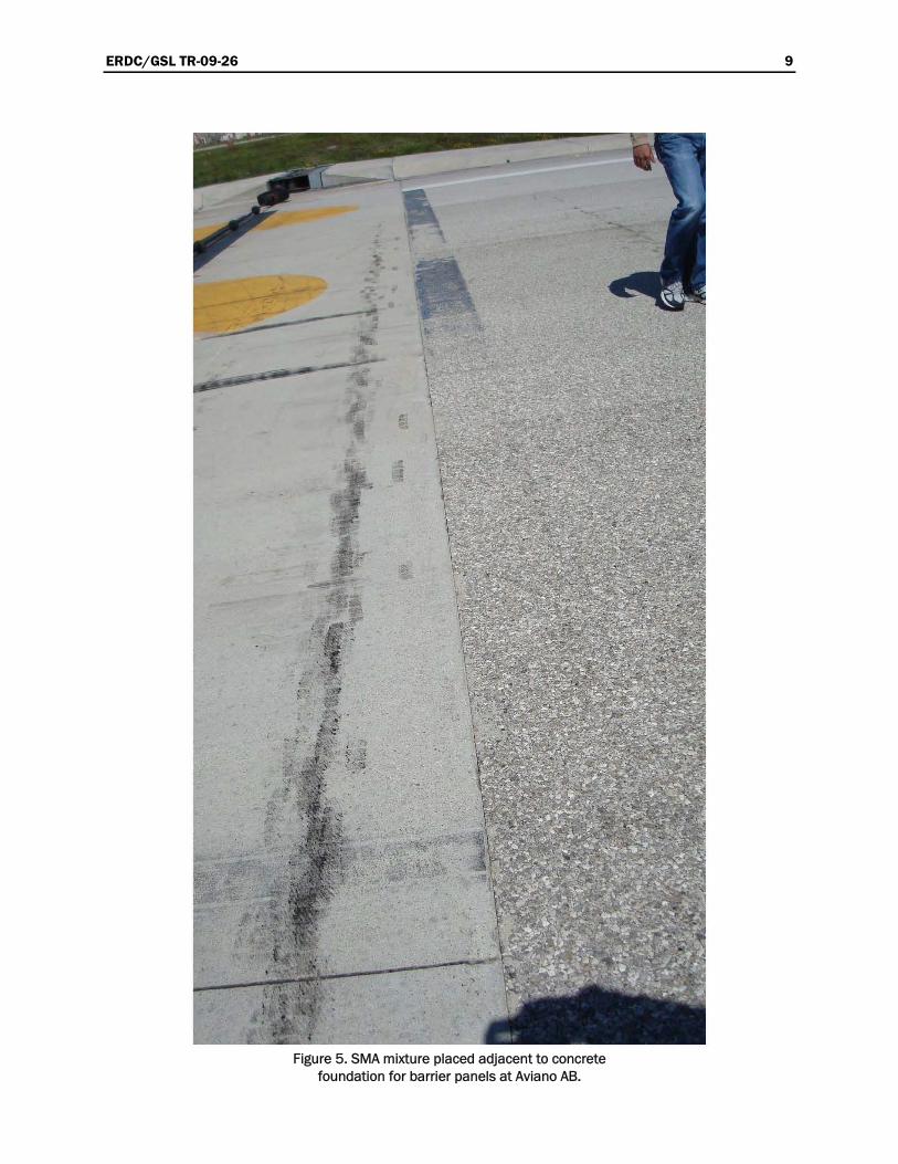
The UHMW polyethylene panels at Aviano AB were inspected on May 12, 2008. The existing pavement was an asphalt pavement with the concrete panel foundation extending approximately 10 ft on either side of the pan-els (Figure 4). The asphalt pavement surface consisted of stone matrix asphalt (SMA) that was placed in 1999 (Figure 5). The placement of the panels does not meet the guidelines documented in AFI 32-1043, Appendix A8, but the performance of the panels and pavement has been very good according to the local staff. The guidelines say that the pavement type should not change within 200 ft of the barrier panels. In this case, the pavement type changed from SMA to concrete at approximately 10 ft from the panels. The concern with this type of design is that the hook may hit a lip at the pavement transition point and skip over the cable. Based on comments from the local staff, there has been no known problem with the hook skipping since the installation of the panels.
The panels were placed in 1999 when the asphalt was milled and overlaid with SMA. The edge of the SMA mixture that was adjacent to the panels had been cut back with a saw, indicating that the SMA was probably in place when the panels were placed. The SMA surface was then likely used to form the concrete. The concrete was placed immediately adjacent to the SMA, leaving no room for sealant. No sealant was used between the con-crete and the SMA, but the performance looked excellent at the time of inspection. There was no breaking over or any other damage to the SMA. There was some very minor spalling of the concrete (Figure 6).
A sealant was used between the panels and the adjacent concrete and between the panel units. At the time of the inspection, the sealant had been recently placed. It had performed well in some locations (Figure 7) and not so well in others (Figure 8). Figure 8 shows how some of the sealant had been lost from the joint in a couple of locations. There was some spalling of the concrete adjacent to the panels and at the contraction joint (Figure 9).
There was some noticeable scarring of the polyethylene panels near the middle of the runway, where most of the traffic passed over the cable. The

ERDC/GSL TR-09-26 8
Figure 4. UHMW polyethylene panels at Aviano AB.
ERDC/GSL TR-09-26 9
Figure 5. SMA mixture placed adjacent to concrete foundation for barrier panels at Aviano AB.

ERDC/GSL TR-09-26 10
Figure 6. No damage of the SMA and slight spalling of the concrete slab at Aviano AB.
Figure 7. Sealant in good shape adjacent to panels at Aviano AB. Note lack of sealant in anchor bolt recess.
repeated beating of the cable over the panels eventually led to this scar-ring, which appears to be very minor. This damage was typical of that seen on a number of projects. However, the panels still appeared to be in good overall shape (Figure 8).

ERDC/GSL TR-09-26 11
Figure 8. Sealant in poor shape adjacent to panels at Aviano AB.
Figure 9. Some spalling of concrete adjacent to panels and at contraction joint at Aviano AB.
Guidance for installing the panels states that they should be placed such that the gap between the panels lines up with the contraction or construc-tion joints in the concrete. It is even more important to ensure that the joints do not line up with the anchors. This could result in failure of the anchor. In at least one case, the contraction joint was lined up within 1 in. of the anchors (Figure 10), but there was no noticeable performance prob-lem.

ERDC/GSL TR-09-26 12
Figure 10. Anchors for panels placed very close to contraction joint in concrete at Aviano AB.
The anchor bolts appeared to be in good shape; however, there was some noticeable rust on the surface. On many projects, the cavity around the anchor bolt is sealed with sealant to prevent water from entering. There was no sealant in these cavities, and there does appear to be corrosion to the top of the anchors where they were exposed. This did not appear to be a significant problem at the time of inspection. It is doubtful that any significant amount of water could seep around these anchor bolts and get underneath the panel.
The performance of the panels and the adjacent pavement was good at Aviano. The sealant appeared good in some places, but it did not perform well in others. Overall, the sealant was not performing very well. This poor performance of the sealant was not unusual. In fact, none of the projects investigated had sealant that performed well for a reasonable period of time. The sealant usually adheres to the asphalt or concrete reasonably well, but it does not adhere to the polyethylene panel very well.
There did not appear to be any warping of the panels resulting in the need to plane the surface of the panels. The panel dimensions generally appeared to be 2 by 5 ft.

ERDC/GSL TR-09-26 13
Buckley Air Force Base, Colorado
Buckley AFB was not visited as a part of this study, but some pictures (taken on May 8, 2007) were supplied showing the UHMW polyethylene panels (Figure 11) on this runway. While there was not much information about the panels as far as time placed, etc., there has been a significant amount of traffic using this runway. The panels appeared to be in good shape and vary in size from 2 ft wide by 2.5 ft long up to 2 ft wide by 5 ft long. The top of the panels appeared to be slightly lower than the adjacent pavement, as recommended.
Figure 11. Overview of UHMW polyethylene panels at Buckley AFB.
The pavement adjacent to the panels was concrete. There was no damage to the concrete caused by the cables, but there was some scarring of the surface where the cable had beaten against the concrete (Figure 12). It is possible that some of the minor spalling that had occurred next to the pan-els was caused by the beating of the cable against the edge of the concrete. It is also possible that snow removal equipment could have caused some of the damage.

ERDC/GSL TR-09-26 14
Figure 12. Condition of sealant around UHMW polyethylene panels at Buckley AFB.
The sealant appears to have some issues, with some of the sealant debonded from the concrete and/or panel (Figure 12). This likely resulted from the expansion and contraction of the adjacent materials during temperature changes. It is not clear what type of sealant was used on this project, but most bases have used silicone sealant.
The joints between the panels appeared to match the joints in the concrete (Figure 12 and Figure 13). There appeared to be some minor spalling in the adjacent concrete adjacent to the panels and adjacent to the longitudinal joint perpendicular to the panels. Some of this spalling may have been caused by snow removal equipment or, perhaps, damage from the cable.
The reservoirs around the top of the anchors were not sealed. There was some rust on the exposed surface of the anchors, but this did not appear to be a significant problem.

ERDC/GSL TR-09-26 15
Figure 13. Joint between panels match joint in concrete for panels at Buckley AFB.
Overall, the panels appeared to be performing satisfactorily, but the sealant appeared to be a problem. While there was some damage to the concrete, the amount of damage was minimal.
Davis-Monthan AFB, Arizona
The panels at Davis-Monthan AFB were inspected on April 16, 2008. The barrier, which was constructed approximately 9 to 10 years prior to the inspection, consisted of panels placed in concrete with the concrete extending approximately 10 ft on one side of the panel and then changing to asphalt mixture (Figure 14). The concrete continued out past the recommended 200 ft on the opposite side of the barrier.
Some of the joints in the polyethylene panels had uneven widths (Figure 15). It is likely that this was caused by temperature and warping effects as well as the beating of the cable on the surface of the panel. It is also possible that the anchors held the panel in place, not allowing it to move immediately adjacent to the anchors, thus resulting in the partial closing of the joint during hot weather in between the anchors but not at

ERDC/GSL TR-09-26 16
Figure 14. UHMW polyethylene panels at Davis-Monthan AFB within approximately 10 ft of change in pavement type.
Figure 15. Variable width of joints in polyethylene panels at Davis-Monthan AFB.
the anchors. If the uneven gap was caused by the anchors, it would be expected that the gap would vary on all sides of the panel. This is not the case; the gap closes on the short side of the panel, thus supporting the thought that it is the cable beating on the panels that is causing the closing of the joints. While this closing of the joints appeared to be causing no immediate problem, it does make it very difficult to reseal the joint and expect to get satisfactory performance.

ERDC/GSL TR-09-26 17
This placement of the panels does not meet the guidelines documented in AFI 32-1043, Appendix A8, but the performance appears to be acceptable. The guidelines say that the mix type should not change within 200 ft of the barrier panels. In this case, the mix type changed at approximately 10 ft on one side of the panels. The traffic that would be using this cable would be coming from the side where the type of pavement changed, raising some questions about the possibility of hook skip.
The sealant in the joint between the concrete and the polyethylene panel was in poor shape. In some cases, the sealant had been lost, and in others it had pulled away from the panels and adjacent pavement (Figures 15 and 16). There was some spalling in the concrete adjacent to the panels. The damage is likely caused by the high amount of expansion of the panels during temperature increases and the possibility that incompressibles were able to get into the joints and result in high pressure being exerted on the concrete pavement during hot weather.
Figure 16. Condition of joint between concrete and polyethylene panel at Davis-Monthan AFB.
There was some damage to the top of the panels due to the beating of the cable on the panels (Figure 17). Of all of the panels surveyed, this appears to be the only occurrence of this problem, indicating that this may be a material defect or the result of some other problem, such as some type of spill. The panels were still performing reasonably well even though this damage had occurred.

ERDC/GSL TR-09-26 18
Figure 17. Damage to polyethylene panel likely caused by cable beating on surface of panel at Davis-Monthan AFB.
Eglin AFB, Florida
The panels at Eglin AFB are shown in Figure 18. The adjacent pavement is asphalt. The photo shown as Figure 18 was taken in January 2005 and was provided to ERDC for inclusion in this study. Based on the photo, there appears to be no particular problem with the adjacent pavement. There did appear to be some loss of asphalt mixture adjacent to the panels, but this appeared to be a minor issue at the time the photo was taken.
For the most part, the joint sealant appears to be in acceptable shape in this photo, but it is not known what type of sealant was used or how long it had been in place.
The size of the panels appears to be approximately 2 by 5 ft.

ERDC/GSL TR-09-26 19
Figure 18. Overview of UHMW polyethylene panels at Eglin AFB.
Eielson AFB, Alaska
The panels at Eielson AFB were inspected on June 25, 2008. Each of the two arresting systems inspected consisted of panels placed in concrete with the concrete extending out over 200 ft in both directions (Figure 19). The panels on the south end of the runway were constructed in 2001, and the panels on the north end of the runway were constructed in 1995.
The joints had been sealed, but in many spots the sealant had been completely removed (Figure 20). Figure 20 shows some spalling in the concrete adjacent to the panels. This spalling was likely caused by snow removal equipment but could have been caused by incompressibles in the joints or by the cable beating against the concrete. In the best locations,

ERDC/GSL TR-09-26 20
Figure 19. Overview of UHMW polyethylene panels at Eielson AFB showing concrete on both sides of the panels (south end of runway).
Figure 20. Loss of joint sealer between panels and concrete pavement (south end of runway) at Eielson AFB.
the sealant was in reasonably good shape, but in many locations it did not perform well. In at least one location the backer rod that was underneath the sealant was damaged and exposed (Figure 21). It is not clear if the backer rod was damaged during construction or if something happened after construction to cause the damage and exposure of the backer rod. It is interesting that the concrete is spalled slightly in the same area. This damage may be the result of the cable beating against the concrete, snow removal equipment, or some other occurrence.

ERDC/GSL TR-09-26 21
Figure 21. Exposure of backer rod between panels and concrete pavement (south end of runway) at Eielson AFB.
An overview of the panels on the north end of the runway is provided in Figure 22. Typical spalling of the concrete is shown in Figure 23.
Figure 22. Overview of UHMW polyethylene panels at Eielson AFB showing concrete on both sides of the panels (north end of runway).

ERDC/GSL TR-09-26 22
Figure 23. Typical spalling in concrete adjacent to panels at north end of runway at Eielson AFB.
Elmendorf AFB, Alaska
The panels at Elmendorf AFB were inspected in June 2008. Observations made during these inspection trips are summarized below.
The pavement on Runway 34, which was 6 to 8 years old at the time of inspection, was in reasonably good shape (Figure 24). There was a strip of
Figure 24. Overview of UHMW polyethylene panels on Runway 34 at Elmendorf AFB.

ERDC/GSL TR-09-26 23
concrete, approximately 4 ft wide, on the surface on both sides of the pan-els. There was some deterioration (Figure 25) in the asphalt mix adjacent to the concrete next to the panels. The deterioration primarily consisted of loss of material from the asphalt mixture immediately adjacent to the concrete strips. This damage was likely the result of snow plow damage and/or some construction deficiency immediately adjacent to the concrete strips. It appeared that the asphalt mixture had been patched for a width of approximately 1 ft on both sides of the concrete slabs. The arresting system on Runway 34 violated the recommendations of the AFI by changing from asphalt to concrete within 200 ft of the arresting cable.
Figure 25. Some damage to the asphalt mixture adjacent to the concrete strip on Runway 34 at Elmendorf AFB.
The sealant in the joints between the panels and the concrete and between adjacent panels was in poor shape (Figure 26). It appeared that the joints were initially sealed with some type of sealer, and the performance was poor. The joints were then sealed with another sealer (Figure 27), which looked like a rubberized asphalt sealant, to help hold the old sealant in place and to waterproof the joints. This rubberized sealant was actually applied to the surface of the panels and the adjacent pavement and was not placed directly in the joints. It appeared that this rubberized sealant adhered to the surface of the panels as well as the adjacent pavement. It is doubtful, however, if this sealant would perform satisfactorily when placed in the joints where the amount of movement is very high.

ERDC/GSL TR-09-26 24
Figure 26. Condition of joint sealant on Runway 34 at Elmendorf AFB.
Figure 27. Excessive sealant on the pavement surface on Runway 34 at Elmendorf AFB.
The panels appeared to be in satisfactory shape. The recesses at the top of the anchors appeared to have been sealed, but some of this sealant had worn off, exposing the ends of some of the anchors. There was no noticeable problem with the anchors; however, for the most part, they were covered with sealant (Figure 28) and could not be inspected.

ERDC/GSL TR-09-26 25
Figure 28. Partially sealed anchors on Runway 34 at Elmendorf AFB.
The asphalt mixture appeared to have been placed by machine in the transverse direction adjacent to the concrete strips. The paver then paved the remaining asphalt on the runway in the longitudinal direction. This approach allowed the contractor to do a better job of getting adequate density immediately adjacent to the concrete strip.
The barrier on Runway 06 had concrete pavement on both sides of the panels. The concrete was 3 to 4 years old. The panels were placed with the long dimension in the longitudinal direction (Figure 29). This is not the procedure recommended by the AFI. There did not seem to be any particu-lar problem due to this orientation, but it does use much more of the expensive panels. In warmer climates, this will also likely cause much more expansion and warping problems.
The condition of the adjacent pavement was very good, with only very minor spalling and some minor scarring of the surface due to action of the cable under traffic (Figure 30). The condition of the panels was good, with no particular problems. The sealant appeared to be intact for most of the joints (Figure 31), but there was some loss in bond between the sealant and the panels (Figure 32).

ERDC/GSL TR-09-26 26
Figure 29. Overview of panels on Runway 06 at Elmendorf AFB.
Figure 30. Minor surface wear of the pavement surface and rounding of the edges on Runway 06 at Elmendorf AFB.

ERDC/GSL TR-09-26 27
Figure 31. Sealant in reasonably good condition on Runway 06 at Elmendorf AFB.
Figure 32. Sealant in poor condition on Runway 06 at Elmendorf AFB.
The 24 end of the runway had asphalt pavement adjacent to the barrier panels (Figure 33). There was a concrete strip on the surface on both sides of the panels. The width of the concrete strips appeared to be approxi-mately 2 ft. There was some minor scarring of the concrete surface due to the action of the cable under traffic. There was some loss of aggregate in the asphalt mixture but no significant cracking.

ERDC/GSL TR-09-26 28 ERDC/GSL TR-09-26 28
Figure 33. Overview of panels on Runway 24 at Elmendorf AFB. Figure 33. Overview of panels on Runway 24 at Elmendorf AFB.

ERDC/GSL TR-09-26 29
There was also a bump between the asphalt pavement and the concrete strip caused by the concrete protruding above the asphalt mixture (Figure 34). Grinding is a good method to make this smooth at this location, as well as any other location having a similar problem. One concern is that this bump will cause the hook to skip and not engage the cable.
Figure 34. Bump between asphalt pavement and concrete strip on Runway 24 at Elmendorf AFB.
The panels appeared to be in good shape with no significant damage. The sealant between the concrete strip and the asphalt pavement appeared to be performing satisfactorily in much of the area but not well in others. The sealant between the panel and the concrete strip was not performing satisfactorily (Figures 35 and 36). The anchors had been sealed and could not be inspected. There was no evidence that there were any problems with the anchors.
Hill AFB, Utah
Hill AFB was visited on December 6, 2007, and the panels on Runway 14/32 were inspected. This runway was an asphalt pavement that was overlaid in 2005. The polyethylene panels were removed from the underlying foundation, and the asphalt was placed up to and over the concrete foundation. The asphalt was then cut out to a point slightly away from the panels to allow room for the panels and sealant. The panels were

ERDC/GSL TR-09-26 30
then replaced. The overall condition of the panels, sealant, and adjacent asphalt is shown in Figure 37.
Figure 35. Condition of sealant between the concrete and asphalt pavements was generally good on Runway 24 at Elmendorf AFB.
Figure 36. Poor performance of sealer between two adjacent panels and between the panels and the adjacent concrete on
Runway 24 at Elmendorf AFB.
The asphalt surface, which was only 2 years old at the time of inspection, was in good shape. Some grinding of the asphalt surface had been done adjacent to the panels to provide a smooth surface over the asphalt mix

ERDC/GSL TR-09-26 31
and across the panels. The panels at this location were 2 by 10 ft, and the tie-downs were 10 ft apart. This length of panels exceeds that recom-mended by the AFI on cable systems.
Figure 37. Overview of panels on Runway 32 at Hill AFB.

ERDC/GSL TR-09-26 32
The manual recommends that the length of each panel be 4 ft, but not to exceed 5 ft. The primary reason for this is that the longer panels will result in more warping, resulting in significant problems. Significant movement with temperature changes had occurred at the time of inspection, leaving a gap of over 1 in. between panels. The sealant did not bond very well to the panel edges. This has been a problem since these types of panels began to be used in the United States over 15 years prior to the preparation of this report and would be expected to be even a bigger problem with these long panels. The surface of the panels appeared to be slightly below the surface of the asphalt as recommended.
As shown in Figure 38, the condition of the asphalt was reasonably good adjacent to the panels. There was some breaking over of the asphalt, but at the time the panels were inspected, this was not a problem. The tie-downs are recommended to be placed no closer than 2 ft from the end of the pan-els, and it can be seen that it is much closer. There was no damage to the asphalt from the cable or hooks on the end of the runway in which the cable was being used.
Figure 38. Condition of panels, sealant, and adjacent asphalt at Hill AFB, Runway 32.
After completing the asphalt overlay in 2005, personnel at Hill AFB decided to remove the asphalt for approximately 200 ft on each side of the panels and replace with concrete. At the time of the inspection, this concrete had been placed on the 14 end of the runway, but the panels had

ERDC/GSL TR-09-26 33
not been replaced. A trench was being cut in the concrete in the area in which the panels were going to be placed, as shown in Figure 39.
Figure 39. Saw cuts prior to removal of concrete for replacement of polyethylene panels
on Runway 14 at Hill AFB.
The asphalt on the 32 end of the runway was scheduled to be removed in the spring of 2008 and replaced with 400 ft of concrete (200 ft on each side of the panel, just as constructed on the 14 end).
Holloman AFB, New Mexico
The pavements containing barrier cables at Holloman AFB were investi-gated on December 7, 2007. Three runways at Holloman (16/34, 04/22, and 07/25) had barrier cables, and the barrier cables on all three were investigated. There were barrier cables on five of the six ends, including 34, 16, 04, 22, and 25. Each of these barriers was evaluated and is dis-cussed below.

ERDC/GSL TR-09-26 34
Photos of the panels on Runway 34 are provided as Figures 40 and 41. The concrete on this runway end was placed in 2005. The panels were also replaced in 2005. On this runway, the concrete adjacent to the panels was an extension of the concrete ends. This extension required that
Figure 40. Overview of barrier cable on Runway 34 at Holloman AFB.
Figure 41. Condition of panels, sealant, and concrete on Runway 34 at Holloman AFB.

ERDC/GSL TR-09-26 35
approximately 500 ft of additional concrete be used to tie into the exten-sion and go approximately 200 ft past the UHMW panels. The center por-tion of the runway was asphalt, but the portion of the pavement around the panels was concrete.
The size of the panels used on this project was 2 by 5 ft. Silicone sealant was used to seal around the panel edges. Tie-downs were placed at approximately 10-ft intervals. The condition of the concrete adjacent to the panels was good (Figures 40 and 41). Although the condition of the panels was good, they did have to be ground down in some places to keep the panels slightly below the surface of the adjacent concrete. The panels tend to warp during temperature changes, occasionally requiring the panels to be ground to be made smooth.
The concrete on the 16 end of the runway was placed in 1991. The panels were replaced in 2005. As indicated above, the concrete here was an exten-sion of the concrete ends. On this end of the runway, the tie-downs were placed at 15-ft intervals. This spacing seemed to result in more damage to the pavement since the cable was able to move more under traffic. Also, the panels did not extend the full width of the runway, resulting in some damage in the areas past the end of the panels. It appears that the panels should have been placed a greater distance, resulting in the end of the pan-els being closer to the end of the cable.
The condition of the concrete adjacent to the panels was reasonably good considering that the concrete was 16 years old when inspected. There were some problems with the sealant, especially between the panels. Fewer problems were noted with regard to the sealant between the concrete and the panels. For the most part, the sealant looked good (Figures 42 and 43). It is clear from Figure 43 that additional sealant was added in various loca-tions as needed.
The asphalt and panels on runway end 22 were 12 years old (Figures 44 and 45). The sealant used on this project was a hot pour sealant (ASTM D3406 material). This sealant material was very stiff and was no longer effective in providing the resilience needed to perform as a sealant. Also, some silicone sealant had been used. This sealant was still flexible and able to tolerate the movement caused by temperature changes. There was some breaking off of the asphalt adjacent to the panels. The sealant had lost bond with the polyethylene panels and with the asphalt in some places.

ERDC/GSL TR-09-26 36
There were some pieces of asphalt in the sealant as a result of the asphalt edge being damaged. It is not clear if this damage occurred as a result of traffic or if it occurred as a result of being pulled apart by the sealant dur-ing cold weather as the joints opened. Certainly, some of the breaking
Figure 42. Overview of barrier cable on Runway 16 at Holloman AFB.
Figure 43. Condition of pavement, sealant, and panels at Runway 16 at Holloman AFB.

ERDC/GSL TR-09-26 37
Figure 44. Overview of barrier cable on Runway 22 at Holloman AFB.
Figure 45. Condition of asphalt, sealant, and panels on Runway 22 at Holloman AFB.

ERDC/GSL TR-09-26 38
of the asphalt edge was caused by traffic, since more breakage could be observed in the traffic areas than in other areas.
The panels did not extend the full width of the runway and, as a result, some significant damage had occurred due to the cable beating the pave-ment outside the area having panels. There was no damage to the asphalt caused by the hooks or damage to the asphalt from the cables except where the panels were not installed far enough from the centerline toward the shoulders.
It is also interesting to note that the gap between panels was not constant from one end of the gap to the other. It is believed that the gap was ini-tially equal, but over time there was some distortion within the panel. This distortion could have been caused by the forces formed in the panel due to temperature changes in combination with the restraint of movement caused by the anchors. The distortion was more likely caused as a result of the cable continually beating the surface of the panels, as evidenced by the scarring of the panel surface.
The age of the pavement and panels and the condition of the sealant, pave-ment, and panels on the 04 end was very similar to that on the 22 end (Figures 46 and 47). There was some warping of the panels, sometimes causing the edges of the panels to be higher than the adjacent pavement surface. The civil engineering staff at Holloman AFB made an effort to maintain the surface of the panels slightly below that of the adjacent pave-ment.
The condition of the asphalt that was placed on Runway 25 in 1996 was very good, except adjacent to the panels where some breakage of the edge had occurred. There was very little cracking and very little raveling, and the longitudinal joints were in very good shape as indicated by the fact that they were very difficult to see. The condition of the panels and adjacent sealant and pavement was very similar to that on Runway 22 (Figures 48 and 49). There was some significant warping of the panels, as shown in Figure 49. The joint sealant had lost bond in many cases, and there was some breakage of the asphalt adjacent to the joint.

ERDC/GSL TR-09-26 39
Figure 46. Overview of barrier cable on Runway 04 at Holloman AFB.
Figure 47. Condition of pavement, sealant, and panels on Runway 04 at Holloman AFB.

ERDC/GSL TR-09-26 40
Figure 48. Overview of barrier cable on Runway 25 at Holloman AFB.
Figure 49. Condition of pavement, panels, and sealant on Runway 25 at Holloman AFB.
RAF Lakenheath, England
The pavement and panels at RAF Lakenheath were inspected on May 5, 2008. The pavement surface course was a porous friction course (PFC) that was about 15 years old. The panels were placed in 2007, so they were about 1 year old at the time of inspection (Figure 50). It appears that the

ERDC/GSL TR-09-26 41
friction course was milled transversely for about 10 ft on each side of the panels. This was done to allow a transverse lane to be placed adjacent to the panels. The PFC immediately adjacent to the panels was placed when the panels were placed in 2007. The adjacent pavement was in very good shape (Figures 50 and 51), and the pavement outside this transverse strip of PFC was also in good shape especially considering that it was about 15 years old (Figure 52).
Figure 50. Overview of panels at RAF Lakenheath.
Figure 51. Condition of pavement adjacent to panels at RAF Lakenheath.

ERDC/GSL TR-09-26 42
Figure 52. Condition of 1-year-old PFC and 15-year-old PFC at RAF Lakenheath.
The panels appeared to be in good shape (Figure 53). No sealant was used, so the PFC was placed up against the panels. The gap between panels appeared to be reduced due to beating of the cable near the midpoint of the panel width. The anchors appeared to be in good shape.

ERDC/GSL TR-09-26 43
Figure 53. Panels were in good shape but some unevenness at joint underneath cable likely due to beating of the cable (RAF Lakenheath).
Luke AFB, Arizona
The pavement at Luke AFB, which was inspected on April 21, 2008, was in reasonably good shape (Figure 54). The pavement and panels were approximately 5 years old at the time of inspection. The two sets of barrier panels investigated were installed at the same time and had very similar characteristics. A concrete strip was constructed on either side of the bar-rier cable and extended out for approximately 20 ft. This is contrary to guidance specified in the AFI, which says that no change in pavement type should be made within 200 ft of the cables.
The concrete generally appeared to be in good shape, but there was some localized spalling (Figure 55). The spalling was likely caused by poor qual-ity mixture adjacent to the panels and incompressibles getting into the joints. The incompressibles likely resulted in damage to the concrete dur-ing hot weather when the panels elongated, resulting in significant forces on the concrete.
The panels were in good shape, but there was some wear from the cable and some closing of the joint spacing due to the cable beating on the sur-face of the panels (Figure 56). The wear was very minimal and was not likely to create a problem. However, the closing of the joint between the panels might make it very difficult for the joint sealer to work

ERDC/GSL TR-09-26 44
Figure 54. Overview of panels at Luke AFB.
Figure 55. Some localized spalling of concrete at Luke AFB.
satisfactorily, since the joint would likely completely close during hot weather in the area where the gap is smallest. The sealant between the asphalt and concrete had lost most of its effectiveness (Figure 56).
The original sealant was placed when the panels were installed 5 years prior to inspection, and only some small amount of additional sealer was applied to localized areas.

ERDC/GSL TR-09-26 45
Figure 56. Condition of sealer satisfactory in spots and damaged in other areas at Luke AFB.
The anchors appeared to be in good shape (Figure 57). There was no sealant in the recesses at the anchor ends, and there appeared to be little corrosion, probably due to the dry climate.
Figure 57. Some deformation in the panels and some wear from beating of the cable at Luke AFB.

ERDC/GSL TR-09-26 46
MacDill AFB, Florida
The panels at MacDill AFB (Figure 58) were inspected on March 25, 2008, and were in reasonably good shape. The panels were approximately
Figure 58. Overview of panels at MacDill AFB.

ERDC/GSL TR-09-26 47
3 years old at the time of inspection. The joints adjacent to and between the panels had been resealed approximately 3 months prior to the inspec-tion. In this case, the asphalt pavement was constructed immediately adja-cent to the panels with room remaining for joint sealer material to be added. The joint sealant appeared to be in good shape (Figure 59), but it had been resealed approximately 3 months earlier.
Figure 59. Condition of sealant after 3 months in place at MacDill AFB.
The condition of the pavement adjacent to the panels was satisfactory. However, the texture was open, and it appeared that some of the fines were lost with time. There was some loss of mix immediately adjacent to the panels, much of which was likely due to loss of aggregate during traffic. There was some grinding of the asphalt surface to make it more level with the panels (Figure 60). It appears that, here, the panels expanded in hot weather, pushing the asphalt mixture upward slightly, requiring that grinding be done to make it level.
The anchors could not be inspected since they were sealed at the surface, but there was no evidence that there was a problem with the anchors.

ERDC/GSL TR-09-26 48
Figure 60. Loss of mix adjacent to the panels at MacDill AFB.
McChord AFB, Washington
The panels at McChord AFB were installed in 2004, and by the end of 2007 there were plans under way to remove the panels and use asphalt mixture as a sacrificial surface. The panels that were installed in 2004 were not inspected as a part of this project. There were a number of rea-
-
-
There was some loss of asphalt mixture adjacent to the panels (Figure 62).
sons for electing to remove the panels, including the loss of at least one anchor bolt. Figure 61 shows that the anchor bolt and nut apparently sheared off or was pulled out. This could be the result of improper installation, damage to the anchor when placed, or damage by equipment or traf-fic after placement. The sealant did not perform very well. After a short period of time, the sealant became ineffective due to loss of bond, primarily with the panels.
It appears that this material broke near the edge under traffic, resulting inthe damage and loss of material.

ERDC/GSL TR-09-26 49
Figure 61. Loss of anchor bolt and nut at McChord AFB.
Figure 62. Loss of asphalt mixture immediately adjacent to the panels at McChord AFB.

ERDC/GSL TR-09-26 50
Selfridge ANGB, Michigan
Selfridge ANGB was not visited as a part of this study, but photos of the panels at Selfridge were provided. An overview of the panels is provided in Figure 63. The panels appeared to be in good shape with some very minor spalling of the concrete edge. Generally, the bond between the sealant and the concrete and panels appeared to be good. The recesses in which the ends of the anchor bolts were located were not sealed. The ends of the anchor bolts appeared to be in good shape, with no significant corrosion or other problem. The panels generally appeared to be 2 ft wide by 2 to 4 ft long.
Figure 63. Overview of panels at Selfridge ANGB.
Seymour Johnson AFB, North Carolina
Seymour Johnson AFB was not visited as a part of this project, but photos of one barrier system there were provided. These photos were taken in January 2008. The panels were installed in a concrete pavement. The setting bed deteriorated over a period of time, resulting in the panels deforming near the middle of the panels (Figure 64). There are several reasons that the setting bed may have deteriorated, but one likely cause is
water getting underneath the panels and exerting pressure on the setting

ERDC/GSL TR-09-26 51
Figure 64. Deformed panels at Seymour Johnson AFB.
bed material under traffic. Another likely cause is that the quality of the setting bed may have been deficient. The recommended solution here is to remove the panels, remove and replace the setting bed, and then reinstall the panels. Some of the panels have been damaged and may need to be replaced before reinstalling. It also appears that there might be some wear near the middle of the panels, such as that observed on other projects.
It also appears from Figure 64 that the tie-downs were not located cor-rectly in the panels. The guidance indicates that the tie-downs should be placed in the middle of the panels, but here it can be seen that the tie-down is within 1 ft of the edge and very near the anchors.
Figure 65 appears to show one or two anchors sticking up above the top of by the panels deforming as a result
of deterioration of the setting material or may be caused by some other
the panels. This may have been caused
reason. If the anchors do stick up above the panels, they should be ground down sufficiently to keep them below the panel surface.
As shown in Figures 64 and 65, it is clear that the sealant has not per-formed satisfactorily. There was no sealant in the recesses around the anchors.

ERDC/GSL TR-09-26 52
Figure 65. End of anchor sticking up near top of panels at Seymour Johnson AFB.
Shaw AFB, South Carolina
,
-crete placed in which to construct the barrier system. The top portion of
At this location, a keyway was cut in the side of each panel to allow sealant
nt
ance at other locations, this improvement in sealer performance was almost certainly
al-e.
At Shaw AFB, four areas having arresting cables were inspected on April 42008. An overview of the panels at the 22 end of Runway 22 R (right) isprovided in Figure 66. The adjacent pavement is concrete. It appears that a section of concrete approximately 15 ft wide was removed and new con
the concrete in the middle of the new concrete slab was then removed approximately 2 ft wide and deep enough to allow for the setting bed and the panels to be placed. The panels were generally 2 by 4 ft.
to fill. This provided additional sealant and an effective wider joint to be filled. This often resulted in improved performance. The sealant did not always bond to the panel, but the sealant in the keyway allowed the sealato stay in place. In fact, Figure 67 shows that the sealant appears to bond better to the panel than to the concrete. Based on perform
the result of the keyway. Even with the better bond to the panel, the seant was not very effective. It appeared to fail in adhesion to the concret

ERDC/GSL TR-09-26 53
Figure 66. Overview of panels on Runway 22 R at Shaw AFB.
Figure 67. Performance of sealant at Runway 22 R at Shaw AFB.
Sealant was used to fill the recess at the end of each anchor. In most cases this sealant in the recess was performing satisfactory; however, in a few cases, there was some loss of sealant (Figure 68). Two types of sealant were used at this location, silicone and GARDOX®. In the opinion of the local staff, GARDOX®, produced by W. R. Meadows, Inc., provided the best results. Even though some moisture had gotten through the joints and underneath the panels, there had been no noticeable pumping.

ERDC/GSL TR-09-26 54
Figure 6 AFB.
4 ft.
ent was removed and replaced when the panels were installed.
8. Loss of sealant in recess for anchor at Runway 22 R at Shaw
No warping was noticeable at the time of inspection. According to the local staff, warping was not a big issue, probably because the panels were no more than 4 ft long.
The panel system at the 4 end of Runway 22-4 R was approximately 15 months old at the time of inspection. The adjacent pavement was con-crete. An overview of the cable system is shown in Figure 69. At the time of inspection, the cable had been moved off the runway.
It appeared that a section of concrete approximately 15 ft wide was removed, and new concrete placed in which to construct the barrier sys-tem. The top portion of the concrete in the middle of the new concrete slab was then removed approximately 2 ft wide and deep enough to allow for the setting bed and the panels to be placed. The panels were generally 2 by
The sealant had pulled away from the concrete but still appeared to be intact as a result of the keyway in the panels (Figure 70). The joints in thepanels did not always match the joints in the concrete (Figure 71).
The panel system at the 22 end of Runway 22-4 L (left) (shown in Figure 72) was constructed in 1997. The adjacent pavement is concrete. It appears that a width of 12 to 15 ft of the existing concrete pavem

ERDC/GSL TR-09-26 55
Figure 69. Overview of panels at Runway 4 R at Shaw AFB.
Figure 70. Sealant pulled away from concrete at Runway 4 R at Shaw AFB.

ERDC/GSL TR-09-26 56
Figure 71. Joi at Shaw AFB.
he panels were in good shape at the time of inspection. While there were some sealant problems, much of the sealant was performing well (Figure 73). The sealant was generally not performing well when placed in the joint between adjacent panels. The recess at the end of the anchors was sealed, and for the most part the sealant appeared to be performing satisfactorily.
nt in panels does not match joint in concrete at Runway 4 R
Figure 72. Overview of panels on Runway 22 L at Shaw AFB.
T

ERDC/GSL TR-09-26 57
Figure 73. Performance of sealant and offset of joints in panels and
concrete on Runway 22 L at Shaw AFB.
gure 74. Offset of joint between panels and joint in concrete at Runway 22 L at Shaw AFB.
The joints between the panels did not always match the joints in the concrete (Figures 73 and 74). In fact, the joint in the concrete in Figure 70 is very close to the anchors. The joint in the concrete can lead to a weak point in the foundation underneath the panels and result in loss of the anchors.
Fi

ERDC/GSL TR-09-26 58
The panel system at the 4 end of Runway 22-4 L was built in 2006. This panel system was inspected on April 4, 2008. An overview of this panel system is provided in Figure 75.
lso ems between two adjacent panels (Figure 76). The keyways were
used in the panels, and it can be seen that the sealant in between the
Figure 76. Performa y 4 L at Shaw AFB.
Figure 75. Overview of panels at Runway 4 L at Shaw AFB.
The joint sealant for location 4 had pulled away from the concrete and ahad probl
nce of joint sealants at Runwa

ERDC/GSL TR-09-26 59
panels had not performed very well. However, it had not been dislodged from the pavement due to the extra width of sealant required as a result the keyways. The recess at the en
of d of each anchor had been sealed, and the
sealant was performing very well in each recess.
Figure 77. Joints in concrete do not match joints between panels at
There was no noticeable warping of the panels and no observed water pumping issues. The joints between the panels did not always match the joints in the adjacent concrete (Figure 77).
Runway 4 L at Shaw AFB.
Spangdahlem AFB, Germany
The panels at Spangdahlem AFB were inspected on May 8, 2008. The barrier consisted of panels placed in concrete with the concrete extending approximately 10 ft on either side of the panels (Figure 78).
A SMA mixture that was placed in 2007 was the surface used on the remainder of the pavement (Figure 79). This placement of the panels does not meet the guidelines documented in AFI 32-1043, Appendix A8, but the performance had been good according to the local staff. The guidelines say that the mix type should not change within 200 ft of the barrier panels. In this case, the mix type changed at approximately 10 ft from the panels.

ERDC/GSL TR-09-26 60
Figure 78. Overview of panels at Spangdahlem AFB.
The panels were placed in 1998 and did not have to be removed during construction since the SMA mixture was not immediately adjacent to the panels. The size of the panel appears to be 2 by 5 ft. There is no damage of the SMA next to the concrete slab, but the SMA was only 1 year old at the time of inspection. Sealant was used between and around the panels, but the sealer was in poor shape at the time of inspection. The sealant used around the panels appeared to be silicone type sealant. There was no sealer in the recess around the anchor bolts. The sealer between the SMA and concrete was only 1 year old and inspection (Figure 80).
hich had been previously repaired, in the edge of the concrete slabs adjacent to the panels (Figure 81). It appears that
g
ints in the panels (Figure 82).
was in good shape at the time of
There was some damage, w
some spalling had occurred, probably as a result of the panels expandinduring the summer time or use of snow removal equipment during the winter. The joints in the concrete did not exactly match the jo
The overall condition of the panels was good. The sealant was in poor condition, very similar to most other locations. There appeared to be no performance problems with the anchor bolts. There was no sealant around the anchor bolts. Some spalling had occurred in the adjacent concrete.

ERDC/GSL TR-09-26 61
Figure 79. Surface of SMA pavement at Spangdahlem AFB.
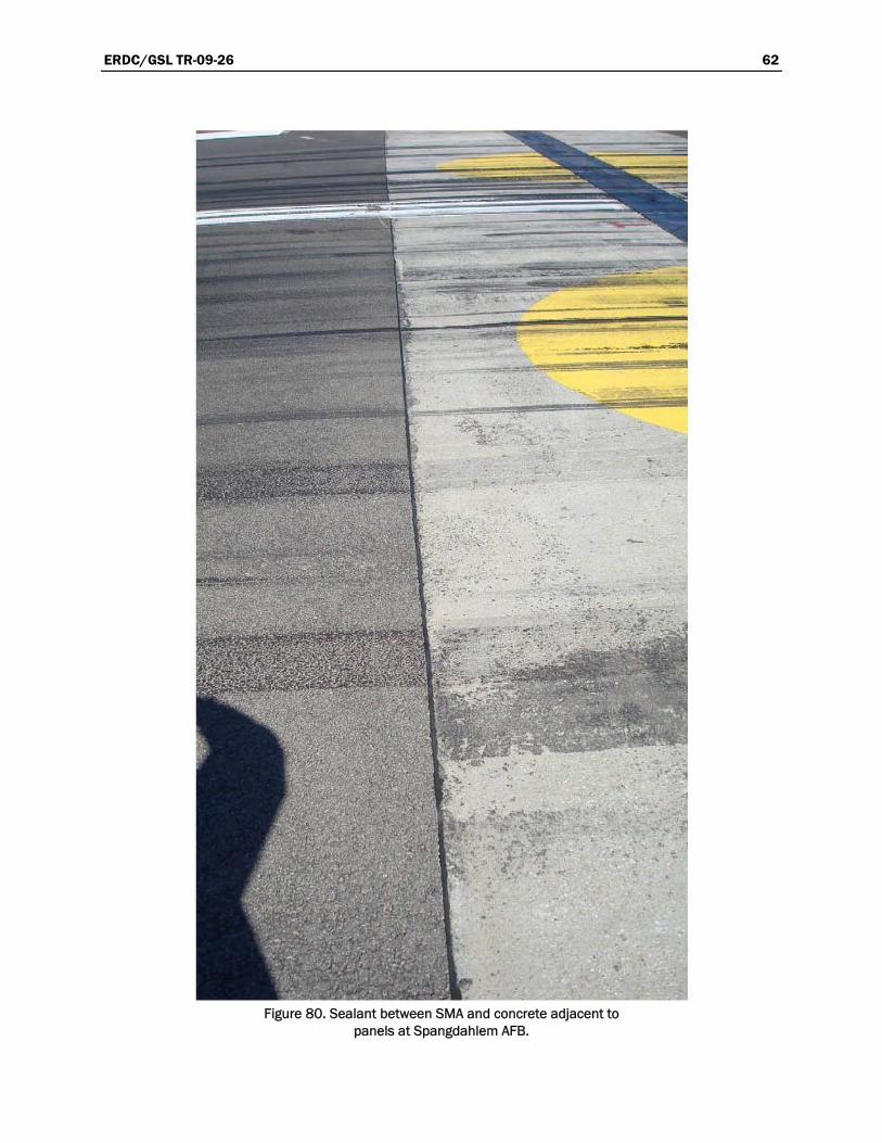
ERDC/GSL TR-09-26 62
Figure 80. Sealant between SMA and concrete adjacent to panels at Spangdahlem AFB.
, .
-:~: .:
•

ERDC/GSL TR-09-26 63
Figure 81. Repair of concrete adjacent to panels at Spangdahlem AFB.
Figure 82. Joints between panels did not match joints in adjacent concrete at Spangdahlem AFB.
Tinker AFB, Oklahoma
The panels at Tinker AFB were not inspected as a part of this study, but photos were provided. These photos were taken in 2004. An overview of the panels is provided as Figure 83.
The keel sectio n each side of the keel. The panels, which appeared to be 2 by 5 ft, seemed to be placed
n was concrete, and asphalt mixture was used o

ERDC/GSL TR-09-26 64
Figure 83. Overview of panels at Tinker AFB.
;

ERDC/GSL TR-09-26 65
for the full extent of the concrete pavement. They actually ended immedi-ately adjacent to the asphalt portion of the pavement.
The sealant in the longitudinal joints did not appear to be performing satisfactorily. There did not appear to be any sealant in the anchor bolt recesses (Figure 84). There also appeared to be some minor spalling in the concrete adjacent to the panels.
Figure 84. Lack of sealant in recess at end of anchor at Tinker AFB.

ERDC/GSL TR-09-26 66
Tynda
Tyndall AFB was visited on March 21, 2008 to inspect the panels and for
condition in most cases; however, there were some places where the sealer had pulled away from the panel or
contain sea
ll AFB, Florida
pavements around the barrier cables. An overview of the panel system Runway 13 L is provided in Figure 85.
The sealer appeared to be in good
concrete. Many of the recesses at the openings cut for the anchors did not ler (Figure 86).
Figure 85. Barrier cables at Runway 13 L at Tyndall AFB.

ERDC/GSL TR-09-26 67
Figure 86. Barrier cable at Runway 13 L at Tyndall AFB showing no sealant in anchor recess.
The joints in the concrete should be matched with the joints between the panels when the panels are placed. There were some cases where this did not happen. In fact, in at least one case, the joints in the concrete were lined up with the anchors in the panels (Figure 87).
The panels at Runway 13 L appeared to be in good condition; however, there is some surface deterioration due to the cable whipping under traffic (Figure 88). The condition of the pavement adjacent to the panels was good.
The panels on Runway 31 R were replaced in 2006. An overview of this panel system is shown in Figure 89. The recesses around the anchor ends had been sealed and were generally still sealed (Figure 90) at the time of inspection. One of the recesses, shown in Figure 90, did not have sealant, and the end of the anchor was beginning to show some rusting. The sealant in the joints was generally good, but some pulli m the sides could be seen (Figure 90).
ng away fro
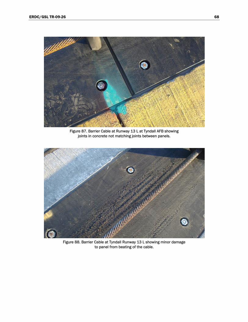
ERDC/GSL TR-09-26 68
Figu ng joints in anels. re 87. Barrier Cable at Runway 13 L at Tyndall AFB showi
concrete not matching joints between p
Figure 88. Barrier Cable at Tyndall Runway 13 L showing minor damage to panel from beating of the cable.

ERDC/GSL TR-09-26 69
Figure 89. Overview of barrier cable at Runway 31 R at Tyndall AFB.
Figure 90. Rust in anchor recess where sealer had been lost at Runway 31 R at Tyndall AFB.

ERDC/GSL TR-09-26 70
An overview of the pa igure 91.
The recesses at the end e cases,
the surface had performance of the sealant and some minor spalling of the adjacent concrete (Figure 94).
nels on Runway 31 L (BAK-12) is shown in FThese were replaced in 2005. For the most part, the sealant was performing very well (Figure 92).
Figure 91. Overview of barrier cable (BAK-12) at Runway 31 L at Tyndall AFB.
of the anchors had been sealed, but in somthis sealant was beginning to be lost. The condition of the pavement adjacent to the panels was good.
The cable had not caused any damage to the panels, but some scarring of occurred (Figure 93). There was some loss of

ERDC/GSL TR-09-26 71
Figure 92. Barrier cable (BAK-12) at Runway 31 L at Tyndall AFB showing good sealant.
Figure 93. Some mi cable beating the surface under traffic at Runway 31 L at Tyndall AFB.
nor scarring at BAK-12 due to the

ERDC/GSL TR-09-26 72
Figure 94. Some sealant damage at BAK-12 and some minor spalling
in the adjacent concrete at Runway 31 L at Tyndall AFB.
The sealant between the panels and the adjacent concrete was in good con-tion, but the sealant in the joints between the panels had lost its bond to
the panels (Figure 100). This loss of bond is due to the large amount of movement during temperature changes. The joint generally reduces from an opening of up to 1 in. during cold weather to nearly closed during hot weather. It is very difficult for a sealant to perform satisfactorily with this high amount of movement.
An overview image of Runway 31 L (E-5) is shown as Figure 95. There is concrete on one side of the panels and asphalt on the opposite side. On the side with asphalt, there is approximately a 1-ft strip of concrete between the panels and the asphalt.
The panels were in good shape with some minor scarring on the surface (Figure 96). The sealant was in good shape in the joints, but the recesses had not been sealed (Figure 97). The adjacent pavement was in good shape on both sides of the panels.
The panels are generally in good condition, but there was some deviation in surface elevation between adjacent panels (Figure 98). This problem is most likely due to warping of the panels during temperature changes. An overview of the panels on Runway 13 R is shown as Figure 99.
di

ERDC/GSL TR-09-26 73
Figure 95. Overview of panels (E-5) at Runway 31 L at Tyndall AFB.
Figure 96. Condition of panels (E-5) and sealant at Runway 31 L at Tyndall AFB.
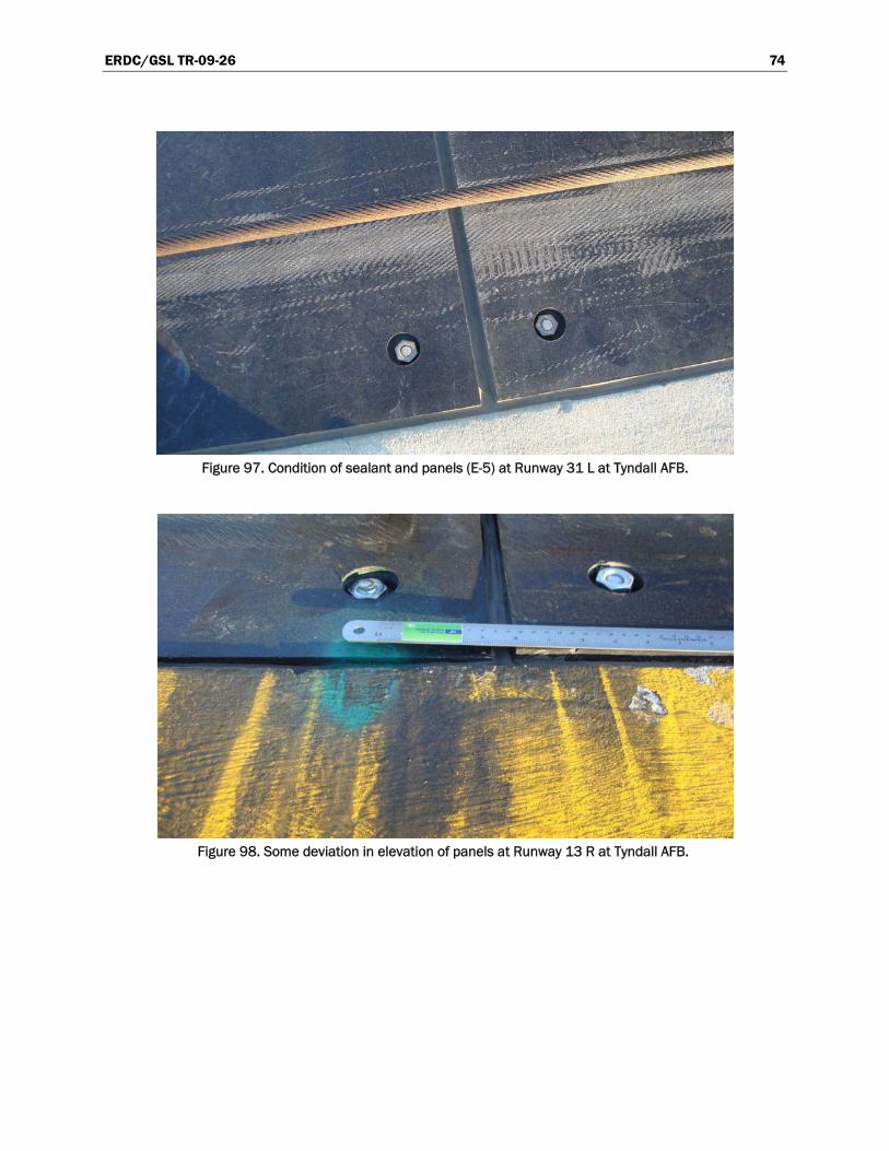
ERDC/GSL TR-09-26 74
Figure 97. Condition of sealant and panels (E-5) at Runway 31 L at Tyndall AFB.
Figure 98. Some deviation in elevation of panels at Runway 13 R at Tyndall AFB.

ERDC/GSL TR-09-26 75
Figure 99. Overview of barrier cable at Runway 13 R at Tyndall AFB.

ERDC/GSL TR-09-26 76
Figure 100. Loss of sealant effectiveness at joint between panels at Runway 13 R at Tyndall AFB.

ERDC/GSL TR-09-26 77
4 Obser
BarrieLoca
vations and Discussion
A significant number of air bases were visited to review the condition of the UHMW polyethylene panels, the adjacent pavement, and the sealant. The primary purpose of the study was to look at the condition of the pave-ment, sealer, and panels and make recommendations about how to improve the performance on future projects.
The age of the panels and adjacent pavement surfaces varied from less than 1 year up to 15 years. Certainly, the age of the panels and pavements has a significant effect on performance, but it appeared from all of the vis-its that most of the problems were related to poor performance of the seal-ant and the effects of temperature changes on the elongation, shrinkage, and warping of the panels. If placed correctly, the panels for the arresting cable system have been shown to provide good performance for up to 15 years and longer with routine maintenance to keep the joints sealed. The asphalt pavement surface adjacent to the panels was shown to last up to approximately 15 years, and the concrete pavement adjacent to the panels lasted even longer. A summary of performance of the panels investigated is provided in Table 1. A summary of the performance problems observed is provided in Table 2.
Table 1. Summary of performance for sites inspected.
r Cable tion
Overall Condition of Cable System
Adjacent Pavement Type
Pavement Age, years
Age of Panels, years Comments
Av
e els
een iano Good Asphalt 9 9
Approx. 10-ft-wide concretstrip on both sides of panbefore start of asphalt. No joint and no sealer betwasphalt and concrete.
Buckley Satisfactory Concrete ---- -----
Davis-Mont
and
han Fair
Concrete and asphalt ---- 10
Concrete on one sideasphalt with 10-ft strip of concrete on other side. Damage to panels.
Eglin Good Asphalt ----- -----
Eielson south end Good Concrete 7 7
Eielson north end Satisfactory Concrete 13 13

ERDC/GSL TR-09-26 78
Barrier Cable Location
Overall Condition of Cable System
Adjacent Pavement Type
Pavement Age, years
Age of Panels, years Comments
Elmendorf 34 Fair Asphalt ----- -----
Asphalt pavement on both sides with 2- to 3-ft concrete strips between panels and asphalt.
Elmendorf 06 Satisfactory Concrete 3-4 3-4
Panels placed with long dimension in longitudinal direction.
Elmendorf 24 Satisfactory Asphalt 3-4 3-4
Panels placed with long dimension in longitudinal direction. Asphalt on both sides of panels after 2-ft concrete strip.
Fair Asphalt 2 -----
Panels 10 ft long. Plan to remove asphalt for 200 ft on each side of panel and
he
placed over barrier foundation and cutback to allow placement of panels.
replace with concrete. Tlast asphalt overlay was
Hill 32
Hill 14
Asphalt pavement was recently replaced with concrete pavement and panels not replaced at time of inspection.
Holloman 34 Good Concrete 2 2
Holloman 16 Good Concrete 16 2
Holloman 22 Fair Asphalt 12 12
Holloman 04 Fair Asphalt 12 12
Holloman 25 Fair Asphalt 12 12
Lakenheath Good Asphalt 1 1
PFC placed transversally adjacent to panels. No joints and no sealer.
Luke Satisfactory Asphalt 5 5
Asphalt on both sides after approximately 15-ft concrete slabs. Some spalling problem.
MacDill Fair Asphalt ----- 3
McChord Poor Asphalt ----- 3
Planned to remove the panels and use asphalt surface.
Selfridge Good Concrete
Seymour Johnson Poor Concrete ----- -----
Loss of setting bed caused deformation.
Shaw 22 R Satisfactory Concrete ----- ------
Shaw 4 R Satisfactory Concrete ----- 1

ERDC/GSL TR-09-26 79
Barrier Cable Overall Condition of
Adjacent Pavement Pavement
Location Cable System Type Age, years
Age of Panels,
omments years C
Shaw 22 L Good Concrete ----- 11
Shaw 4 L Satisfactory Concrete ----- 2
Spangdahlem Satisfactory Asphalt 1 10 Asphalt on both sides after concrete strips.
Tinker Satisfactory Concrete ----- -----
Tyndall 13L center Good Concrete ----- 2
Tyndall 31R Good Concrete ----- 2
Tyndall 31L BAK-12 Good Concrete ----- 3
Tyndall 31L E-5 Good
Concrete and asphalt ----- 4
Concrete on one side and asphalt on opposite side after strip of concrete
Tyndall 13R Satisfaction Concrete ----- 3
Table 2. Summary of problem areas.
Problem Areas
Location Pavement Panels Anchors Sealants
Aviano Minor spalling of adjacent concrete Satisfactory
Some corrosion at top of anchor
Localized loss bond
of
Buckley Minor spalling of adjacent concrete Satisfactory
Minor corrosion Localizeat top of anchor
d sealant problems
Davis-Monthan
Minor sadj Sealant problems
palling of acent concrete
Surface damage and warping Satisfactory
Eglin Minor breakinover of asphalt
gf actory
Satis actory Satisfactory Satisf
Eielson south end
Spalling of adjacent concrete Satisfactory
Some coat top o
rrosion f anchor
Much sealant dislodged
Eielson nend
orth g of nt concr tisf ory
inor cot top o
Spallinadjace ete Sa act
Ma
rrosion f anchor
Much sealant dislodged
Elmendorf 34 Satisfactory sfactory SatisfacSati tory
Additional sealing done but losing bond
Elmendorf 06 Satisfactory Satisfactory Satisfactory
ealing done with localized loss of sealant
Some res
Elmendorf 24 sf ry tisfac ry
Some resealing done with localized loss of sealant Satisfactory Sati acto Sa to

ERDC/GSL TR-09-26 80
Problem Areas
Location Pavement Panels Anchors Sealants
Hill 32
Some breaking of the asphalt edge and some grinding required Satisfactory Satisfactory
Sealant has lost bond to panel and pavement
Hill 14 At the time of inspection, panels being reinstalled after asphalt replaced with concrete
Holloman 34 Satisfactory Some grinding required Satisfactory
Sealant has lost bond with panels and pavement
Holloman 16 Satisfactory Satisfactory Satisfactory
Generally satisfactory but some loss of bond
Holloman 22
Some breaking of the asphalt adjacent to panels
Some warping requiring some grinding Satisfactory
Loss of flexibility and bond
Holloman 04
Some breaking of the asphalt adjacent to panels
Some warping requiring some grinding Satisfactory Loss of bond
Holloman 25
Some breaking of the asphalt adjacent to panels
Some warping occurring Satisfactory Loss of bond
Lakenheath Satisfactory Some elongation of panel Satisfactory No sealer used
Luke Localized spalling of concrete
Some elongation of panel Satisfactory
Minor localized bond loss
MacDill
Some break over adjacent to panels and some grinding Satisfactory Satisfactory Satisfactory
McChord
Some breaking of the adjacent asphalt Satisfactory Loss of anchor Loss of bond
Selfridge Satisfactory Satisfactory Satisfactory Satisfactory
Seymour Johnson Satisfactory
Depression in panel due to inadequate support
Anchor end protruding up above pavement surface Loss of sealant
Shaw 22 R Satisfactory Satisfactory Satisfactory Loss of bond
Shaw 4 R Satisfactory Satisfactory Satisfactory Loss of bond and loss of sealant
Shaw 22 L Satisfactory Satisfactory Satisfactory Loss of bond and loss of sealant

ERDC/GSL TR-09-26 81
Problem Areas
Location Pavement Panels Anchors Sealants
Shaw 4 L Satisfactory Satisfactory Satisfactory Loss of bond and loss of sealant
Spangdahlem Some spalling of adjacent concrete Satisfactory
Minor corrosion at top of anchor Loss of bond
Tinker Satisfactory Satisfactory Satisfactory Loss of bond in some locations
Tyndall 13 L center Satisfactory
Small amount of surface wear from cable Satisfactory
Satisfactory except in localized areas
Tyndall 31 R Satisfactory Satisfactory Satisfactory
Satisfactory except in localized areas
Tyndall 31 L BAK-12 Satisfactory Satisfactory Satisfactory
Satisfactory except in localized areas
Tyndall 31 L E-5 Satisfactory Satisfactory Satisfactory Satisfactory
Tyndall 13 R Satisfactory Satisfactory Satisfactory Satisfactory
While the panels had generally provided good performance, there were a number of the panel installations that were not in compliance with the existing AFI 32-1043, Appendix A8, requirements. The most common deviation from the AF requirements was a change in pavement type within 200 ft of the barrier cables. Another common deviation was not matching the joint in the adjacent concrete pavement with the joint between adja-cent panels. Other deviations observed included panels longer than recom-mended, long dimension of panels placed in longitudinal direction instead of transverse direction, and openings for tie-downs and anchors in wrong location.
The panels that were inspected were generally in good shape. There were often problems with sealants and performance of adjacent pavements, but panels and anchor systems were generally in good shape. There appeared to be some closing of the joints immediately underneath the cables for some panels (Figure 15). This resulted in the joint width being reduced in the mid-width portion of the panel as the cable repeatedly impacted the panel under traffic. This will almost certainly cause damage to the joint sealant in hot weather when the space between the panels often com-pletely closes. When this closing of the joint occurs, it tends to squeeze out

ERDC/GSL TR-09-26 82
any sealant, resulting in loss of effectiveness. In the worst cases, it is necessary to he joint resealin
There was on re the panels had actually lost somtegrity h me o ce ma
the panels was worn away as a result of the cable impacting on the panels. t clear
was related to some other problem, such as fuel spillage or other issue. Since this was observed at onl ation, it is likely n
e d whe his typ
The pavement next to the panels was typically in reasonably w lways ll am eling
that had occu p ver, in most cases, this was minor and no ant pr of the pavements
h elem with the n
tu . e emestructed to be slightly higher than the adjacent panels to help minimize the potential for cable skip. As the traffic passes over the asphalt pavement,
n eup slightly higher than the pan
With the con , i hat the causes aften a small amount of small pieces of broken concrete between the
sealant and the concrete pavement (Figure 23). It is possible that the seal-ame i les g join
aged the concrete during hot weather, when the panels and pavement mixture expa pressure on the concrete. It is also possible
ome damage o a res m also hat, in s, th may the
result of cable impact under tr
cting atch in lt mi fconfinement is needed, and good compactive effort is required. The final
ld be smo gy to b
under traffic is significantly reduced. An example of patching a narrow me acent ls is igur
recreate t before g.
e location whe (Figure 17). In t
e of the sur-terial from face in is case, so f the surfa
It is no if this was caused by some imperfection in the panels or if it
y this one locn using t
ot a problem that has to b considere e of panel.
good condi- or spallingtion. There as almost a some sma ount of rav
rred next to thet a significe area immediat
anels. Howeoblem. Manyly adjacent to the panels. The major prob-
had been patched in t
asphalt pavemere under traffic
ts appeared to be some breaking over of the By design, thasphalt mix asphalt pav nt is con-
some amou t of breaking oft n occurs where the asphalt mixture stands els.
crete pavement t is not clear w re, but there was o
ant bec neffective, and incompressib ot into the t and dam-
nded, exerting cases, that, in s ccurred as ult of snow re oval equip-
ment. It appeared t some case is damage have been affic.
an asphaConstru a quality p xture can be di ficult. Good
compacted surface shou oth and sli htly higher than the adjacent panels. When good density is obtained, the susceptibilit reaking over
section im diately adj to the pane shown in F es 101 and 102. The first step is to cut out the bad material and square up the hole.

ERDC/GSL TR-09-26 83
Figure 101. Remove damaged material and square up hole.
Figure 102. Fill hole with mix, level, and compact.
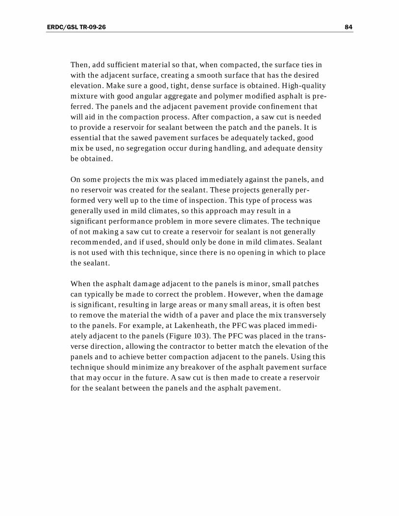
ERDC/GSL TR-09-26 84
Then, add sufficient material so that, when compacted, the surface tiewith the adjacent surface, creating a smooth surf
s in ace that has the desired
elevation. Make sure a good, tight, dense surface is obtained. High-quality
nt
to the panels is minor, small patches can typically be made to correct the problem. However, when the damage
s-f the
is e
d the asphalt pavement.
mixture with good angular aggregate and polymer modified asphalt is pre-ferred. The panels and the adjacent pavement provide confinement that will aid in the compaction process. After compaction, a saw cut is needed to provide a reservoir for sealant between the patch and the panels. It is essential that the sawed pavement surfaces be adequately tacked, good mix be used, no segregation occur during handling, and adequate density be obtained.
On some projects the mix was placed immediately against the panels, andno reservoir was created for the sealant. These projects generally per-formed very well up to the time of inspection. This type of process was generally used in mild climates, so this approach may result in a significant performance problem in more severe climates. The techniqueof not making a saw cut to create a reservoir for sealant is not generally recommended, and if used, should only be done in mild climates. Sealais not used with this technique, since there is no opening in which to place the sealant.
When the asphalt damage adjacent
is significant, resulting in large areas or many small areas, it is often best to remove the material the width of a paver and place the mix transverselyto the panels. For example, at Lakenheath, the PFC was placed immedi-ately adjacent to the panels (Figure 103). The PFC was placed in the tranverse direction, allowing the contractor to better match the elevation opanels and to achieve better compaction adjacent to the panels. Using thtechnique should minimize any breakover of the asphalt pavement surfacthat may occur in the future. A saw cut is then made to create a reservoir for the sealant between the panels an

ERDC/GSL TR-09-26 85
Figure 103. Asphalt mixture placed up against panels at RAF Lakenheath.
The technique being used for construction of the panel system in existing asphalt pavements should be continued. The asphalt pavement material should be removed to the width and depth specified. Next, the specified materials should be placed to the depth required and compacted to the
required density. It is important that good density in the base material underneath the concrete support be obtained. For best density, the required 1-ft base thickness should be placed in 6-in. lifts and compacted to the required density. Placing the material in one 12-in. lift may result in adequate density on the surface of the base, but it may have lower density underneath. This lower density material in the pavement structure can result in some additional compaction under traffic, resulting in the eleva-tion of the panels being lower than required.
There was no area of the pavement adjacent to the panels where signifi-cant segregation, raveling, cracking, shoving, or rutting was taking place. Except in areas where warping had occurred or excessive breakover of the asphalt mixture had occurred adjacent to the joint, there were no areas where pavement roughness adjacent to the panels appeared to be a prob-lem. When warping occurred, there was sometimes a bump created as a result of the panels having an uneven surface. When these bumps occurred, they were made level by grinding or planing the surface, as shown in Figure 104. Otherwise, hook skip could be a problem.

ERDC/GSL TR-09-26 86
Figure 104. Grinding surface of panel to make smooth.
ts,
nique.
face between the panels and the asphalt pavement.
As desired, the surface of the panels was almost always slightly lower than the surface of the pavement. However, in some cases, the panels had warped, resulting in portions of some panels protruding above the adja-cent pavement. Except for cases where the panels had warped, due to hot weather, there was not a problem with the panels protruding above the adjacent pavement. When this warping occurs, it is important that the
It was difficult, after the fact, to determine all of the details involving con-struction procedures that had been used around the panels. However, much could be determined. There appeared to be little or no handwork adjacent to the panels. In almost all cases, the adjacent asphalt was placed by machine traveling in the longitudinal direction. On at least two projeca lane of asphalt mixture was placed in the transverse direction, immedi-ately adjacent to the panels. The remaining lanes tied into the transverse mat and were placed in the longitudinal direction. This process allows the first lane to be placed against the panels, resulting in improved compac-tion at the interface. This process did not appear to damage the panels anddid appear to perform well, based on the limited use of this techAfter compaction, a reservoir is created by making a saw cut at the inter-

ERDC/GSL TR-09-26 87
material protruding above the adjacent pavement be ground down to make it level with the adjacent pavement.
The joint sealant was a major problem. In almost every case, the sealant had lost adhesion to the panels and had pulled back, allowing water to seep into the pavement. The most common sealant used was Dow silicone, but like other sealants used, this material did not perform well. In some cases, a number of sealants had been tried, with little success. As the seal-ant continued to fail in areas, the failed material was replaced, sometimes with a different sealant, resulting in a number of sealants existing at a given location at any one time. At one base, a material called GARDOX® was the preferred sealant. It may be necessary to coat the side of the pan-els with a primer/bonding material that will help provide improved bond between the sealant and the binder. A keyway in the side of the panels, similar to that done at one location, could improve performance of the sealant. Certainly, limiting the panel length will reduce the movement and
r, of the
he
stem to ensure that anchors are not lost and to identify other problems that exist. If anchors become
-
r of is
with. Even though this lack of sealant in the recesses occurred, it did not appear to result in any significant problem. There was some minor corrosion but
improve the probability that a sealant will perform well. It is doubtful thatany sealant will work successfully with the joint width varying from 0 in. up to 1 in., which can easily happen if the panels are too long. There are several options that might help improve performance of the sealants: reduce length of panels, use keyway to make effective joint width greatemake wider joint, improve sealants, and improve surface properties panels to allow better bond.
The anchors for the most part were performing well. In one very unusual situation an anchor was missing (Figure 61). This almost certainly was tresult of improper installation or unsatisfactory materials. This does pointout a need to regularly inspect the arresting sy
loose, they should be repaired before dislodging, possibly resulting in foreign object damage (FOD) problems.
In most cases, the recesses around the top of the anchors were filled withjoint sealant to help ensure that water did not reach the under side of the panels. Sometimes the sealants in these applications did not work very well, resulting in the sealant being dislodged with time. In a numbecases, there was no sealant in the recesses at the time of inspection. Thwas often the result of not using any sealant in this area to begin

ERDC/GSL TR-09-26 88
not enough to cause a problem. However, since sealing this reservoir does not take much effort, and it will provide some assurance of keeping mois-ture out, it is recommended that these recesses continue to be sealed when the joints are sealed.
The only damage that appeared to be the result of traffic was the damage to the asphalt pavement adjacent to the panels and the scarring on the sur-face of the panels. The damage to the surface of the panels was minimal, so the most significant effect of traffic was on the condition of the asphalt pavement adjacent to the panels.
There were discussions with the local staff on most projects. Generally, those that had used the UHMW polyethylene panels believed that the pan-els provided improved performance over previous methods. Prior to adopting the use of these panels, the area underneath the cables had to be repaired at least yearly and, in many cases, more often.
There is a need to improve performance of the sealants. Many bases have tried various types of sealants to help provide some help in this area. Those involved able system would like to determine how to minimize the warping of the panels. At one
ce, ss
.
t continued to the edge of the pavement, water can pond and cause performance problems in
n to
in the construction and maintenance of the c
base, a keyway was formed around the edge of each panel so that the seal-ant would fill the recess and hopefully provide overall better performansince the effective width would be greater. While this did not solve the loof bond problem, it did appear to provide some improvement in perform-ance.
Some of the local technical staff reported that water tends to get under thepanels and pump during traffic. This problem was not observed during thesite visits, but apparently it does exist at some locations. While this pumping problem does occur, it does not appear to be a major problem. Water can be trapped where the end of the panels tie into the pavementThere is a reservoir in which the panels are placed. This reservoir ends atthe location the panels will end. If the reservoir is no
some cases. Some bases have actually made saw cuts in the pavement sur-face at these outer portions of the pavement to allow the water to draithe pavement’s edge.

ERDC/GSL TR-09-26 89
5 mendations
er-
Concl
t
ever, this does confirm the need for frequent inspections.
circumstances. There was some damage to the pavement surface adjacent to the pan-
t
Conclusions and Recom
Based on field investigations and discussions with Air Force civil engineing staff, a number of conclusions and recommendations have been devel-oped concerning the performance of the panels, adjacent pavement, and sealant. Specific conclusions and recommendations are provided below.
usions
The use of UHMW polyethylene panels has greatly reduced the amounof maintenance and repairs required under arresting system cables. Even after approximately 15 years of being exposed to the environmentand traffic, very little physical damage had occurred with the UHMWpolyethylene panels.
Panels tend to expand and warp during hot weather, especially when panels exceed the maximum recommended sizes. This can cause the panel to protrude above the pavement surface and increase the possibility of the hook skipping over the cable.
The anchor system for holding the panels in place has worked well,and, when installed correctly, does not appear to need improvement. On one project, an anchor was missing, but this was likely related to installation problems. How
Most of the barrier systems had problems with performance of the sealant. The sealants generally do not bond very well to the UHMW polyethylene panels. One of the problems is the amount of movement of the panels during changing temperatures. As a result of these temperature changes, the joint opening can vary from approximately 1 in. all the way down to almost closed. It is impossible for a sealant to perform satisfactorily under these
els, but this was typically minor. In some cases, the asphalt pavement tended to break off or ravel adjacent to the panels. The concrete pavements typically had some very minor amount of spalling adjacento the joints. Repairs to the asphalt or concrete need to be performedusing best construction practices to ensure satisfactory performance.
When the panels do not extend to the pavement edge, water can be trapped in the area around the end panels, leading to some water issues in these areas. Some pavement issues have developed (between

ERDC/GSL TR-09-26 90
the end of the panels and the anchor for the arresting cable) due to the cable beating the pavement past the panel area.
The most common potential causes of damage to the adjacent pave-ment include cable impacts, expansion of panels during hot weather, incompressible solids in joint, snow removal equipment, and traffic
t t concrete, and openings for tie-downs
and anchors in the wrong location.
Recom
arping of the panels and sealant problems. When placing panels adjacent to concrete
t
lts in only a minimal amount of sealant being added to the joint,
leading to possible adhesive failure during cold weather.
up
of
and without any portion of the anchors becoming loose.
Work is needed to determine the best type of sealant to be used and to identify the best approach for using sealant. Overall, the silicone
crossing over the pavement edge adjacent to the panels. Many projects had some part of the installation of panels that violated
AFI 32-1043. The most common problems were a change of pavement type within 200 ft of the panels, panels too large, joints in panels nolining up with joints in adjacen
mendations
The nominal panel length should be set at 4 ft to help minimize movement during temperature changes resulting in w
pavements, the panels should be cut so that the joints between adjacenpanels match the joints in the concrete.
Place the panel and sealant during average temperatures when the joint opening will be about midpoint, approximately 1/2 in., for opti-mum sealant performance. If the sealant is placed in cold weather, the joint opening will be wider, resulting in excessive sealant being added to the joint and being squeezed out later during hot weather. If the sealant is placed during hot weather, the joint opening is reduced. Thisresu
Final dimensions of the panels will be determined by the joint spacing in the concrete. Continue to use six anchor bolts for full-size panels. As described in the AFI 32-1043, the joints in the panels should linewith the joints in the concrete pavement. The panels should never be placed so that the joint in the concrete lines up with the anchors, sincethis could cause failure of the anchoring system.
The biggest problem with the anchor system is the potential for lossa nut or the nut working loose and sticking up above the top of the panels. Regular inspections are needed to ensure that the anchoring system is working satisfactorily without any portion protruding above the top of the panel

ERDC/GSL TR-09-26 91
sealant that has been recommended appears to provide the best . It is joints
between the panels and between the panels and adjacent pavement.
e
gh reduced panel size (recommended to be 4 ft), improved
d area, tack around the sides of the pavement
e d
ngs. The patch should h
be can be
d and compacted. However, when the problem the se
then a
ure that there is no
s
er
performance of the sealants used, although problems continuerecommended that silicone sealant continue to be used to seal
A keyway was used around the perimeter of panels at one location and it appeared to improve performance of the sealant. The potential for using the keyway should be further investigated. In addition, it is recommended that work be done to identify a primer to be used on thpanels to improve bond. Some improvement in the bond is needed throusealant material, use of primer on surface of panel, or use of keyway in the side of the panel. Further work is needed to investigate use of primer, improved sealant material, and use of keyway.
When patching asphalt pavements adjacent to panels, cut out and square up the damageedge, tack the bottom of the remaining hole, add new material to the prepared area, and provide adequate compaction. It is preferred to usmixes that contain good crushed aggregate and polymer modifieasphalts to minimize damage from aircraft loadiextend at least 2 in. into sound pavement and have a minimum widtof 6 in. The mix should be placed up against the panels and then cut out with a saw after compaction to form a 1/2-in.-wide joint that can sealed. When the area to be patched is small, the damaged area cut out by hand, replaceis large, a width of 10 ft adjacent to the panel should be removed in transverse direction. This will permit a paver to work in the transverdirection and will allow for best placement and compaction. If both sides of the panels have large amounts of material to be patched, 10-ft lane should be removed and replaced on each side of the panels.
Regular inspections of the panel system are needed to ensure that maintenance is performed when needed and to ensimminent concern for FOD issues. Questions to address during the survey include what is condition of anchoring system? is elevation of panels slightly below elevation of adjacent pavement materials? isealant in good shape? are there incompressibles in joints? is there pumping under traffic? what is the condition of the adjacent pavement? and what is condition of tie-downs?
When it is necessary to place a foundation for the panels, a 12-in. layof base course should be placed and compacted in two 6-in. lifts.

REPORT DOCUMENTATION PAGE Form Approved
OMB No. 0704-0188 Public reporting burden for this collection of information is estimated to average 1 hour per response, including the time for reviewing instructions, searching existing data sources, gathering and maintaining the data needed, and completing and reviewing this collection of information. Send comments regarding this burden estimate or any other aspect of this collection of information, including suggestions for reducing this burden to Department of Defense, Washington Headquarters Services, Directorate for Information Operations and Reports (0704-0188), 1215 Jefferson Davis Highway, Suite 1204, Arlington, VA 22202-4302. Respondents should be aware that notwithstanding any other provision of law, no person shall be subject to any penalty for failing to comply with a collection of information if it does not display a currently valid OMB control number. PLEASE DO NOT RETURN YOUR FORM TO THE ABOVE ADDRESS.
1. REPORT DAAugust 2009
2. REPORT TYPE VERED (From - To) TE (DD-MM-YYYY) Final report
3. DATES CO
5a. CONTRACT NU
MBER
5b. GRANT NUMBER
4. TITLE AND S
Evaluation offor Aircra
T NUMBER
UBTITLE
Ultra High Molecular Weight (UHMW) Polyethylene Panels ft Arresting Systems
5c. PROGRAM ELEMEN
5d. PROJECT NUMB
ER
5e. TASK NUMBER
6. AUTHOR(S)
E. Ray Brow
MBER
n
5f. WORK UNIT NU
7. PERFORMING NIZATION REPORT ORGANIZATION NAME(S) AND ADDRESS(ES) 8. PERFORMING ORGA NUMBER
U.S. Army EngiGeotechnical a3909 Halls FerrVicksbu
ERDC/GSL TR-09-26 neer Research and Development Center
nd Structures Laboratory y Road
rg, MS 39180-6199
9. SPONSORING TOR’S ACRONYM(S) / MONITORING AGENCY NAME(S) AND ADDRESS(ES) 10. SPONSOR/MONI
11. SPONSOR/MONITOR’S RE NUMBER
PORT (S)
Headquarters, 139 Barnes AvTyndall AFB, FL
Air Force Civil Engineer Support Agency enue, Suite 1
32403-5319
12. DISTRIBUTIApproved for
ON / AVAILABILITY STATEMENT public release; distribution is unlimited.
13. SUPPLEME
NTARY NOTES
14. ABSTRACUltra high m States for approximatel en concrete or asphalt is used directly unde ng that the dam-aged area be re A researc Civil Engineer Support Agency at Ty pe and to recom-mend ways to im anels.
(Continued)
T olecular weight (UHMW) polyethylene panels for aircraft arresting systems have been used in the Unitedy 15 years to provide better resistance to erosion of the pavement surface under arresting cables. Wh
r the cables, the pavement surface becomes heavily damaged during a short period of time, requirimoved and patched.
h project was awarded to the U.S. Army Engineer Research and Development Center by the Air Forcendall Air Force Base to inspect a number of polyethylene panels throughout the United States and Euro
prove performance of the panels and the pavement materials and joint sealants adjacent to the p
15. SUBJECT T
Aircraft arrestiJoint sealant
olecular weight polyethylene ERMS
ng systems Pavement damage Thermal effects
Ultra high m panels
16. SECURITY . NUMBER 19a. NAME OF RESPONSIBLE CLASSIFICATION OF: 17. LIMITATION 18OF ABSTRACT OF PAGES PERSON
a. REPORT
UNCLASSIFIED UNCLASSIFIED UNCLASSIFIED
PHONE NUMBER (include
b. ABSTRACT c. THIS PAGE
106 19b. TELEarea code)
Standard Form 298 (Rev. 8-98) Prescribed by ANSI Std. 239.18

14. ABSTRACT (Concluded)
Generally, the UHMW panels have provided much-improved performance, but some changes are needed to improve the overall performance. Several problems have occurred, including warping of the panels, loss of bond between the sealant and the panels, and damage to the adjacent pavement surface when traffic passes over the joint between the panels and the pavement. Items that need improvement include reducing the amount of warping, improving the bond between the sealant and panels, and improving the performance of the asphalt and concrete mixtures adjacent to the panels.