Embed Size (px)
Citation preview

Export Catalogue
STONE wOOl iNSulaTiON SOluTiONS
rOckwOOl fraNcE S.a.S.
111, rue du Château des Rentiers
75013 Paris
Tel. +33 [0]1 40 77 82 82
fax. +33 [0]1 45 86 80 75
www.rockwool.fr
Non
con
trac
tual
doc
umen
t - P
rint
ed o
n pa
per
from
sus
tain
ably
man
aged
fore
sts
- Ja
nuar
y 20
14 -
Des
ign:
FD
C
ExP
oR
t C
ata
log
uE
Photograph this flashcode and find:n our product informationn our catalogues, our videosn and much more...


1
External thermal insulation
Ventilated façade REDAir systEm 46 RockfAçADE 56 RockglAcE 57
Masonry under rendered façade EcoRock 60
Metal cladding RockbARDAgE 114 Rockstyl’systEm: RockbARDAgE unDER RockpAnEl 118
Insulating floors and ceilings
Foundation insulation RockfEu coffRAgE 66
Slab insulation RockfEu REI 60 RsD AnD RockfEu REI 120 RsD 70
Concrete floating floor under screed Rocksol ExpERt 34
Insulating steel flat roofs
Inaccessible RockAcIER b souDAblE 98 HARDRock 2 nu 88 RockAcIER b nu 110
Inaccessible, equipment zones, green & photovoltaic roofs RockAcIER c nu 92 RockAcIER c souDAblE 102 RockAcIER c souDAblE EnERgy 106
HVAC
Heating system/ Domestic hot water Rockwool 800 82 Rockwool 835 84 Rockwool 133 (Ef) 86
Ventilation system and pipework conlIt 150 u 124 conlIt pEnEtRAtIon boARD 126 conlIt fIx 127 conlIt DuctRock 128
Metal frames conlIt stEElpRotEct boARD (Alu) 130
Products contentsQuality of service 2
stone wool, the ultimate insulation par excellence 4
Rockwool 4 in 1, beyond the thermal issue 5
from the centre of the earth to the heart of our buildings 6
stone wool, a natural and healthy product 8
the Environment, a priority for Rockwool 9
Rockwool ExpoRt on line 10
our products by application 12
table of thermal resistances 14
Loft insulation
Horizontal loft lE flocon 2 18 RoulRock kRAft 20
Furnished attics RockmuR kRAft 25
Insulating vertical walls from the inside
Rigid linings on frameworks or masonry RockmuR kRAft 22
RockmuR nu AnD AlpHARock 28 Rockwool 001 32
Insulating concrete flat roofs
Inaccessible Rock up b+ nu 40 Rock up c nu 42 Rock up b+ souDAblE 76 Rock up c souDAblE 78

2
www.rockwool.fr
we are conscious that compliance with our quality of service commitments is a major component of our commercial relations.
our customer service - composed of our sales assistants - and our logistic services, present on each of our production sites, take daily care of your supply with Rockwool products. so, in 2013, millions of square metres of our products were delivered and 30,881 lorries were loaded on our saint-Eloy-les-mines production site alone.
so that we can always guarantee the best logistic performance, your order thus monopolises the whole attention of the Rockwool customer service.
SpECIAL produCtS rAngE our price list shows our standard products for all applications.However, we are able to respond to other special requests for your needs in terms of:
- thicknesses (e.g.: half thickness) - thermal conductivity - mechanical performance - acoustic performance - panel formats, etc.
pACkIngproduct packing may change depending on the production location. Invoicing, however, is always based on the areas delivered.
In 2012, over 30,000 lorries were loaded on the Saint-Eloy-Les-Mines (Auvergne) only production site
your satisfactionat the heart of our preoccupations
QuAlIty of sERvIcE

3
grAnd Export (MAgHrEb - AfrICA)
MEAnS of trAnSport, dELIVErIES And dELIVEry tIMES
IndIrECt (MAInLAnd frAnCE)
Incoterms 2012
usual transport type
building products
roof-flat roof and Cladding products
delivery time
Ex workS
40 Hc container 18 - 20 pallets or bulk
22 palletsproduct availability confirmed by our logistics servicesRefrigerated lorry* 20 - 22 pallets 26 pallets
Articulated lorry, 100 m3 16 - 22 pallets 26 pallets
Cfr
40 Hc container 18 - 20 pallets or bulk
22 pallets Delivery time to port depending on destination countryArrival date confirmed by our logistic services
Refrigerated lorry* 18 - 22 pallets 26 pallets
Articulated lorry, 100 m3 16 - 22 pallets 26 pallets
*availability depending on season
Incoterms 2012
usual transport type
building products
roof-flat roof and Cladding products
delivery time
Ex workS 40 Hc container bulk 22 palletsproduct availability confirmed by our logistics services
Cpt MAInLAnd frAnCE
tautliner lorry see packing in catalogue complete lorry 5 working days - other quantities: 7 to 20 working daystransport supplement: lump sum of 250 € if the number of pallets
is < 6 pallets
QuAlIty of sERvIcE

4
www.rockwool.fr
stone wool, the ultimate insulation par excellence.born from volcanic rock (basalt), stone wool is a pure product of nature. comprising a network of fibres imprisoning cells of dry, stable air, this material comprises 98% basalt and 2% organic binder. It is an infinitely recyclable natural product.
Stone wool is a product benefiting from durability and a positive carbon budget: it is one of those rare industrial products that allows more savings in energy, c02 and atmospheric pollutants than the quantity consumed and/or emitted during its processing. the energy and carbon budgets for stone wool become positive barely 5 five months after installation of the products.
Controlled manufacture to preserve the environment: 98% of the manufacturing waste generated is recycled, including 100% of the wool waste.
M A D E
5
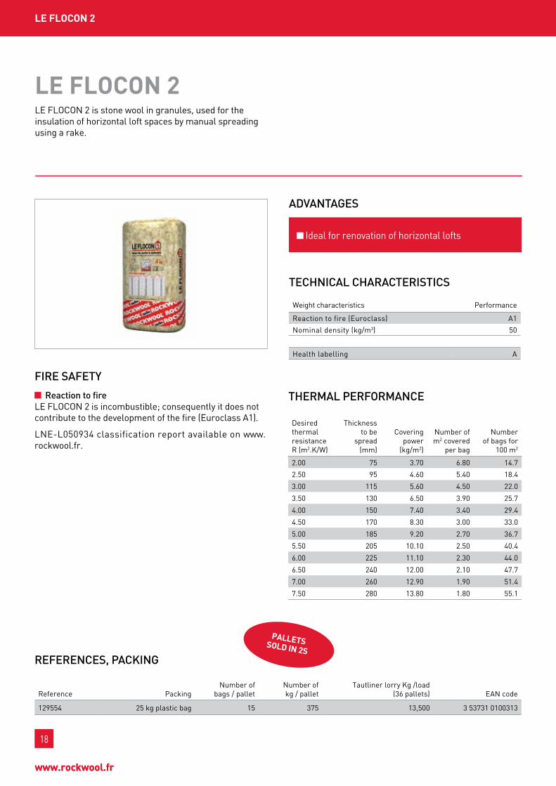
nobody can stand the heat as we do.our products can withstand temperatures up to 1000 ° c, making them exceptionally resistant to fire. In case of fire, this resistance to slow the progress of the fire: it is thus save valuable time relief operations and helps protect the structure of building against avoidable damage. In addition, our products do not emit toxic fumes, which cause 70% of deaths due to fire.our solutions provided passive protection against fire and also serve to improve the performance of other components (fire stop doors for example).
to raise the level of comfort, we reduce the noise.many sounds are acoustic environment part of a room : outside traffic, systems ventilation, discussions... spaces with high sound levels are stressful and exhausting. our insulation solutions and our ceiling panels acoustic dampen noise to improve comfort and quality of life, whether at home or at work.
unmatched durability.our products are designed to deliver a lasting performance. Rockwool solutions remain stable over time and avoid the formation of thermal bridges. our expertise is trusted by prescribers,designers, construction companies and contractors.
our activity is closely linked to nature.we manufacture products and solutions made of volcanic and recycled rock but we also process our waste production processes to new raw materialand we develop our systems to recycle materials from the construction waste.
High performance solutions for the building envelope.
Rockwool 4 in1, beyond the thermal issue
our manufacture from rock, an inexhaustible natural source, allows us to offer insulation quality that is not confined to thermal comfort. In fact the solutions provided to improve protection of people against fire and noise are just as important, in our eyes, as thermal efficiency.
Rockwool "4 in 1" is an unequalled combination of benefits arising directly from the stone wool, in terms of safety (fire resistance), acoustic comfort, longevity and sustainable development. A combination that guarantees a range of high performance products and services.
Durability
Ecological materials
Fire safety
Acoustic comfort

6
www.rockwool.fr
froM tHE CEntrE of tHE EArtH to tHE HEArt of our buILdIngS
roCkwooL, worLd LEAdEr In StonE wooL SInCE 1937
An inexhaustible natural resource, stone wool is mainly made up of basalt volcanic rock. this property makes it a unique insulator.
n natural insulation par excellencethe Rockwool manufacturing process is similar to the natural action of a volcano. the stone wool comprises basalt and recycled materials melted at 1500°c. the liquid mineral mass is transformed into fibre by extrusion, the binder is then added to the mixture. the equipment in our "domestic volcano" has made it an environmentally compliant process.
n why insulate with roCkwooL stone wool?stone wool is a healthy product and beneficial for the quality and comfort of life in a dwelling.stone wool insulation is an economically positive choice. It generates up to 30 % savings on the heating and air conditioning bill.stone wool insulation has a favourable, scientifically measured impact on the environment.Rockwool products save up to 100 times the energy needed for their manufacture. they combat greenhouse gas emissions and pollution.
n Available in all forms and for all activity sectors:- granules- Rolls- semi-rigid and rigid, bare and covered panels- single or double density panels- Internal and external insulation systems- chimney insulation.
A company that listens to you• 274,147 million euros turnover in 2012• 775 employees• A French factory at Saint-Eloy-les-Mines in
Auvergne with an area of 42 hectares• 3 manufacturing lines• Over 3000 customers in france and 500 in Africa
• 4000 product references
the whole Rockwool team are ready to serve you. commercial Department: tel. +33 (0)1 40 77 82 40
Basalt Coke
Weighing
Charge
Melting
Extrusion
Collection
Layering
Cooking
Cutting
Packing
Logistics
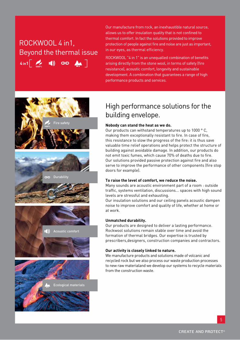
INSULATING DOUBLE SKIN METAL CLADDING
CREATE AND PROTECT®www.rockwool.fr
ROCKBARDAGE
+ thermal performance
+ acoustic performance
+ fire safety
ROCKBARDAGE is the idealsolution to bring metal buildings intocomplete compliance with the thermaland fire regulations.
ANNONCE_PRESSE_ROCKBARDAGE_V3.indd 1 21/03/12 14:33:44
7
froM tHE CEntrE of tHE EArtH to tHE HEArt of our buILdIngS

8
www.rockwool.fr
StonE wooL,a natural and healthy product
roCkwooL And IntErnAL AIr QuALItyframe insulation, the construction of air tight dwellings and controlled ventilation are essential to obtain a better internal environment. well adapted insulation offers a stable, pleasant indoor temperature between 20 and 26°c, whether in cold winters or hot summers.Even costly heating or cooling systems do not allow the elimination of unpleasant air currents caused by air currents.A house should be insolated in the right way. by fitting too little insulation, not complying with the installation rules or not providing sufficient ventilation, you risk seeing hot damp air forming condensation on cold or poorly insulated surfaces. condensation creates humidity that favours the development of moulds and fungi.roCkwooL products have the qualification required for use of the finnish "M1" label for internal air quality. this meets the strictest European requirements, corresponding to an absence of significant emissions of odours, particles or volatile organic compounds.
roCkwooL And HEALtHthe stone wool is classified as non-carcinogen material.Rockwool has chosen to subscribe to the EuCEb (European certification board for mineral wool products) certification mark. this mark, delivered by an independent body, ensures that conformity of Rockwool to the non-carcinogen requirement will be maintained over time. the purpose of the EucEb membership is to certify that our fibres comply with note Q of European Directive 97/96/cE - products exempt from carcinogenic classification.moreover, Rockwool stone wool is classed in group 3 according to the I.A.r.C classification method (International Agency for Research on cancer) and "cannot be classed as a human carcinogen".
CONSTRUCTION M
ATER
IALS EM
ISSION CLASS
M1

9
tHE EnVIronMEnt,a priority for RoCkWooL
Rockwool has a fDEs (fiche de Données Environnementales et sanitaires - Environmental and Health Declaration Sheet) datasheet for each reference and thickness. During the stone wool manufacturing process water is used in closed circuit to limit its consumption.
wHy InSuLAtE?Saving energy.the largest part of private households energy budget concerns home heating or cooling. we underestimate the positive effect of improved insulation and the advantages of stone wool in saving energy and so reducing the energy bill.Heating and air conditioning are the main items in a building's energy consumption. they represent two thirds of the total energy consumption. However, most of this energy is wasted due to inadequate insulation. the use of proven energy efficiency techniques allows a 70 to 90 % reduction in a building's heating or air conditioning needs
poorly insulated buildings are the main source of Co2 emissions.During the last few years, improving the energy efficiency of our housing has excited great interest. this development has been more marked for new buildings. However, in many countries new buildings represent only 1 % of the total number of buildings. the great majority of the remaining 99 % were built before expressions such as "energy crisis" and "global warming" were part of our everyday vocabulary.
EnVIronMEntAL LAbELLIng on VoLAtILE poLLutAnt EMISSIonS froM ConStruCtIon And dECorAtIon produCtSwhat is a VoC?VOCs (volatile organic compounds) include numerous substances that can be of natural or human origin. They are gases and vapours comprising the element carbon and other elements such as hydrogen, the halogens, oxygen, sulphur, etc.
For example, VOCs are emitted during the combustion of fuels or by evaporation during their manufacture, storage or use. The effects of VOCs vary considerably depending on their nature. In health labelling for construction products a list of 10 VoCs is considered: formaldehyde, acetaldehyde, toluene, tetrachloroethylene, xylene, 1,2,4-trimethylbenzene, 1,4-dichlorobenzene, ethylbenzene, 2-butoxyethanol, styrene.
what are the regulatory obligations? since the 1stJanuary 2012, construction and decoration products newly placed on the market are provided with a label that indicates, simply and legibly, their volatile pollutant emission level. Since the 1st September 2013, all construction and decoration products on the market are provided with this label. the products concerned by this new regulation are construction products or wall coverings for use inside buildings, and the products used for their incorporation or application. so partitions, floor coverings, insulation, paints, varnishes, glues, adhesives, etc. are concerned in so far as they are intended for internal use. manufacturers are obliged to put the label defined by the order of 19 April 2011 on the product or its packaging. the products emission level is indicated by a class going from A+ (very low emissions) to c (high emissions), following the principle used for household electrical goods or vehicles.Consumers thus have transparent information that can serve as a new selection criterion. Building owners can also take internal air quality into account as a criterion in their calls for tender for the building construction or renovation.
EMISSIONS INTO INTERNAL AIR

10
www.rockwool.fr
roCkwooL Export on LInEwww.rockwool.fr
more modern, more ergonomic, still just as rich and complete, the rockwool.fr site offers you:- A new search tool- A new document database- new sections (Export)- A "city of solutions" virtual town- A reading room- on line pocket calculators- the Rockwool channel on youtubevisit www.rockwool.fr
your answers just a click away!
tHE rEfLEx:

Isoler les toItures-terrasses béton
Écartez les risques de votre horizonDécouvrez la nouvelle gamme béton de Rockwool, la solution plus sécurisante et plus adaptable. Une nouvelle gamme qui inclut Rock Up B+, RockBoRDeR pour l’isolation des relevés d’acrotères et DoUBle Up, une colle prête à l’emploi. Sécurité incendie maximale, performances mécaniques, thermiques et acoustiques : parce que l’étanchéité des toitures-terrasses ne souffre d’aucun désordre !
www.rockwool.fr
pour encore plus d’informations sur nos produits :scannez ce QR code avec votre smartphone.
phot
os : J
ohn-
Mor
gan,
Roc
kwoo
l, DR
–
annonce_presse_v8_EXE.indd 1 11/12/12 16:12
11
Remove the risks from your horizonDiscover the new Rockwool concrete range, the safer and more adaptable solution. A new range that includes Rock up b+ and RockboRDER for insulating parapet raised edges and DoublE up, a ready to use adhesive. maximum fire safety, mechanical, thermal and acoustic performance: because waterproofing flat roofs cannot suffer from any disorder!
InSuLAtIng ConCrEtE fLAt roofS

Summary table:- The designate the recommended applications for the products.- The designate other possible applications.
* including walkways
our produCtS by AppLICAtIon
roofS VErtICAL wALLS froM InSIdE VErtICAL wALLS froM outSIdE fLoorS & CEILIngS StEEL fLAt roofS ConCrEtE fLAt roofS HVAC
Horizontal loft
furnished attics
Rigid linings on frameworks or masonry
partition walls
masonry under added façade
masonryunder coating
Double skin metal cladding
At the base of formwork
slab insulation
under masonry screed
Inaccessible*
Inaccessible*, equipment zones, green & photovoltaic roofs
Inaccessible*
Inaccessible*, equipment zones, green & photovoltaic roofs
Heating system
ventilation system and pipework
metal frames
lE flocon 2
RoulRock kRAft
RockmuR kRAft
Rockwool 001
RockmuR nu
AlpHARock
REDAir systEm
RockfAçADE
EcoRock
RockbARDAgE
Rockstyl’ systEm
RockfEu coffRAgE
RockfEu REI 60 RsD
RockfEu REI 120 RsD
Rocksol ExpERt
RockAcIER b nu
RockAcIER b souDAblE
HARDRock 2 nu
RockAcIER c nu
RockAcIER c souDAblE
Rock up b+ nu
Rock up b+ souDAblE
Rock up c nu
Rock up c souDAblE
Rockwool 800
Rockwool 835
Rockwool 133
conlIt 150 u
conlIt pEnEtRAtIon boARD
conlIt fIx
conlIt DuctRockconlIt stEEl pRotEct
boARD (Alu)
12
www.rockwool.fr

13
roofS VErtICAL wALLS froM InSIdE VErtICAL wALLS froM outSIdE fLoorS & CEILIngS StEEL fLAt roofS ConCrEtE fLAt roofS HVAC
Horizontal loft
furnished attics
Rigid linings on frameworks or masonry
partition walls
masonry under added façade
masonryunder coating
Double skin metal cladding
At the base of formwork
slab insulation
under masonry screed
Inaccessible*
Inaccessible*, equipment zones, green & photovoltaic roofs
Inaccessible*
Inaccessible*, equipment zones, green & photovoltaic roofs
Heating system
ventilation system and pipework
metal frames
lE flocon 2
RoulRock kRAft
RockmuR kRAft
Rockwool 001
RockmuR nu
AlpHARock
REDAir systEm
RockfAçADE
EcoRock
RockbARDAgE
Rockstyl’ systEm
RockfEu coffRAgE
RockfEu REI 60 RsD
RockfEu REI 120 RsD
Rocksol ExpERt
RockAcIER b nu
RockAcIER b souDAblE
HARDRock 2 nu
RockAcIER c nu
RockAcIER c souDAblE
Rock up b+ nu
Rock up b+ souDAblE
Rock up c nu
Rock up c souDAblE
Rockwool 800
Rockwool 835
Rockwool 133
conlIt 150 u
conlIt pEnEtRAtIon boARD
conlIt fIx
conlIt DuctRockconlIt stEEl pRotEct
boARD (Alu)
these solutions are not exhaustive. to find out about other possible solutions, contact the Rockwool sales department.

14
www.rockwool.fr
tAbLE of tHErMAL rESIStAnCES
ApplIcAtIons pRoDucts REActIon to fIRE
AcERmI cERtIfIcAtE no.
thermal resistance R (m2.k/w) per thickness in mm
15 30 40 45 50 55 60 65 70 75 80 85 90 95 100 105 110 115 120 125 130 135 140 150 155 160 170 180 190 200 220
loft
s Horizontal loftlE flocon 2 A1 -- 2.00 2.70 3.00 3.50 4.00 4.50 5.00 5.50 6.00
RoulRock kRAft f 02/015/001 1.40 1.90 2.35 2.85 3.30 3.80 4.25 5.10
furnished attics RockmuR kRAft f 02/015/025 1.20 1.60 2.00 2.70 3.20
vER
tIc
Al
wAl
ls f
Ro
m
InsI
DE
Inner partitions on frames or masonry
Rockwool 001
RockmuR kRAft f 02/015/025 1.20 1.60 2.00 2.70 3.20
partition wallsRockmuR nu A1 02/015/021 1.20 1.60 2.00 2.70 3.20 3.75
AlpHARock A1 02/015/035 0.85 1.15 1.40 1.70 2.30 2.85
vER
tIc
Al w
Alls
fR
om
tH
E o
uts
IDE masonry under added
façade
REDAir system
RockfAçADE A1 02/015/027 1.50 1.95 2.20 2.80 3.35 3.90 4.20 4.45 4.75 5.00 5.30 5.60
moulded under coating EcoRock
Double skin metal cladding
RockbARDAgE nu A1 04/015/305* 3.20 3.80 4.05
RockbARDAgE REvÊtu A1 08/015/477* 3.20 3.80 4.05
Rockstyl’ systEm
flo
oR
s &
c
EIlI
ng
s foundation insulation RockfEu coffRAgE A1 02/015/053 1.30 1.55 1.80 2.10 2.35 2.60 2.85 3.15 3.40 3.65
slab insulationRockfEu REI 60 RsD A1 07/015/445 1.70 2.00 2.35 2.45 2.60 2.75 2.90 3.05 3.15 3.45 3.75 4.05 4.35
RockfEu REI 120 RsD A1 07/015/443 1.70 2.00 2.35 2.45 2.60 2.75 2.90 3.05 3.15 3.45 3.75 4.05 4.35
concrete floating floor Rocksol ExpERt A1 07/015/449 0.35 0.75 1.05 1.30 1.55 1.80 2.10 2.35 2.60
stEE
l fl
At
Ro
ofs
Inaccessible**
RockAcIER b nu A1 04/015/295 1.00 1.25 1.50 1.75 2.05 2.30 2.55 2.80 2.95 3.05 3.30 3.55 3.85 4.10 4.35 4.60
RockAcIER b souDAblE f 02/015/019 1.00 1.25 1.50 1.75 2.05
HARDRock 2 nu A1 06/015/415 1.25 1.50 1.80 2.05 2.30 2.55 2.80 3.05 3.30 3.55 3.80 4.10
Inaccessible**, equipment zones, green & photovoltaic roofs
RockAcIER c nu A1 02/015/011 1.45 1.70 1.95 2.20 2.45 2.70 2.95 3.20 3.45 3.70 3.95
RockAcIER c souDAblE f 02/015/013 1.45 1.70 1.95 2.20 2.45 2.70 2.95 3.20 3.45 3.70 3.95
co
nc
REt
E fl
At R
oo
fs
Inaccessible**
Rock up b+ nu 340 A1 04/015/297 1.00 1.15
Rock up b+ nu 390 A1 02/015/049 1.30 1.55 1.70 1.80 1.95 2.10 2.20 2.35 2.50 2.60 2.75 2.85 3.00 3.15 3.25 3.40 3.65 3.90 4.05
Rock up b+ souDAblE 348 f 04/015/299 1.00 1.15
Rock up b+ souDAblE 397 f 02/015/051 1.30 1.55 1.70 1.80 1.95 2.10 2.20 2.35 2.50 2.60 2.75 2.85 3.00 3.15 3.25 3.40 3.65 3.90 4.05
Inaccessible**, equipment zones, green & photovoltaic roofs
Rock up c nu 360 A1 03/015/285 1.15 1.40
Rock up c nu 395 A1 02/015/045 1.75 2.05 2.30 2.55 2.80 3.05 3.30 3.45 3.55
Rock up c souDAblE 369 f 06/015/385 1.15 1.40
Rock up c souDAblE 396 f 02/015/047 1.75 2.05 2.30 2.55 2.80 3.05 3.30 3.45 3.55
fIRE REsIstAncE cE cERtIfIcAtE
HvA
c
Rockwool 800 A2-s1,d0*** 0751-cpD.2-008.0-01-01/12
Rockwool 835 A 0751-cpD.2-008.0-01-01/12
Rockwool 133 A2l-s1,d0 0751-cpD.2-007.0-02-01/12
conlIt 150 u m0
conlIt pEnEtRAtIon boARD
m0
conlIt stEEl pRotEct boARD (Alu)
A1
conlIt DuctRock A1
the values of thermal resistances shown are those established by AcERmI. the validity of the certificates can be verified by consulting the database on the website www.acermi.com* Effective thermal performance in current part ** Including walkways*** for Do > 300 mm (if Do ≤ 300 mm classification A2l-s1,d0)

15
ApplIcAtIons pRoDucts REActIon to fIRE
AcERmI cERtIfIcAtE no.
thermal resistance R (m2.k/w) per thickness in mm
15 30 40 45 50 55 60 65 70 75 80 85 90 95 100 105 110 115 120 125 130 135 140 150 155 160 170 180 190 200 220
loft
s Horizontal loftlE flocon 2 A1 -- 2.00 2.70 3.00 3.50 4.00 4.50 5.00 5.50 6.00
RoulRock kRAft f 02/015/001 1.40 1.90 2.35 2.85 3.30 3.80 4.25 5.10
furnished attics RockmuR kRAft f 02/015/025 1.20 1.60 2.00 2.70 3.20
vER
tIc
Al
wAl
ls f
Ro
m
InsI
DE
Inner partitions on frames or masonry
Rockwool 001
RockmuR kRAft f 02/015/025 1.20 1.60 2.00 2.70 3.20
partition wallsRockmuR nu A1 02/015/021 1.20 1.60 2.00 2.70 3.20 3.75
AlpHARock A1 02/015/035 0.85 1.15 1.40 1.70 2.30 2.85
vER
tIc
Al w
Alls
fR
om
tH
E o
uts
IDE masonry under added
façade
REDAir system
RockfAçADE A1 02/015/027 1.50 1.95 2.20 2.80 3.35 3.90 4.20 4.45 4.75 5.00 5.30 5.60
moulded under coating EcoRock
Double skin metal cladding
RockbARDAgE nu A1 04/015/305* 3.20 3.80 4.05
RockbARDAgE REvÊtu A1 08/015/477* 3.20 3.80 4.05
Rockstyl’ systEm
flo
oR
s &
c
EIlI
ng
s foundation insulation RockfEu coffRAgE A1 02/015/053 1.30 1.55 1.80 2.10 2.35 2.60 2.85 3.15 3.40 3.65
slab insulationRockfEu REI 60 RsD A1 07/015/445 1.70 2.00 2.35 2.45 2.60 2.75 2.90 3.05 3.15 3.45 3.75 4.05 4.35
RockfEu REI 120 RsD A1 07/015/443 1.70 2.00 2.35 2.45 2.60 2.75 2.90 3.05 3.15 3.45 3.75 4.05 4.35
concrete floating floor Rocksol ExpERt A1 07/015/449 0.35 0.75 1.05 1.30 1.55 1.80 2.10 2.35 2.60
stEE
l fl
At
Ro
ofs
Inaccessible**
RockAcIER b nu A1 04/015/295 1.00 1.25 1.50 1.75 2.05 2.30 2.55 2.80 2.95 3.05 3.30 3.55 3.85 4.10 4.35 4.60
RockAcIER b souDAblE f 02/015/019 1.00 1.25 1.50 1.75 2.05
HARDRock 2 nu A1 06/015/415 1.25 1.50 1.80 2.05 2.30 2.55 2.80 3.05 3.30 3.55 3.80 4.10
Inaccessible**, equipment zones, green & photovoltaic roofs
RockAcIER c nu A1 02/015/011 1.45 1.70 1.95 2.20 2.45 2.70 2.95 3.20 3.45 3.70 3.95
RockAcIER c souDAblE f 02/015/013 1.45 1.70 1.95 2.20 2.45 2.70 2.95 3.20 3.45 3.70 3.95
co
nc
REt
E fl
At R
oo
fs
Inaccessible**
Rock up b+ nu 340 A1 04/015/297 1.00 1.15
Rock up b+ nu 390 A1 02/015/049 1.30 1.55 1.70 1.80 1.95 2.10 2.20 2.35 2.50 2.60 2.75 2.85 3.00 3.15 3.25 3.40 3.65 3.90 4.05
Rock up b+ souDAblE 348 f 04/015/299 1.00 1.15
Rock up b+ souDAblE 397 f 02/015/051 1.30 1.55 1.70 1.80 1.95 2.10 2.20 2.35 2.50 2.60 2.75 2.85 3.00 3.15 3.25 3.40 3.65 3.90 4.05
Inaccessible**, equipment zones, green & photovoltaic roofs
Rock up c nu 360 A1 03/015/285 1.15 1.40
Rock up c nu 395 A1 02/015/045 1.75 2.05 2.30 2.55 2.80 3.05 3.30 3.45 3.55
Rock up c souDAblE 369 f 06/015/385 1.15 1.40
Rock up c souDAblE 396 f 02/015/047 1.75 2.05 2.30 2.55 2.80 3.05 3.30 3.45 3.55
fIRE REsIstAncE cE cERtIfIcAtE
HvA
c
Rockwool 800 A2-s1,d0*** 0751-cpD.2-008.0-01-01/12
Rockwool 835 A 0751-cpD.2-008.0-01-01/12
Rockwool 133 A2l-s1,d0 0751-cpD.2-007.0-02-01/12
conlIt 150 u m0
conlIt pEnEtRAtIon boARD
m0
conlIt stEEl pRotEct boARD (Alu)
A1
conlIt DuctRock A1
the values of thermal resistances shown are those established by AcERmI. the validity of the certificates can be verified by consulting the database on the website www.acermi.com* Effective thermal performance in current part ** Including walkways*** for Do > 300 mm (if Do ≤ 300 mm classification A2l-s1,d0)
unit used: thk = thickness in mmr = thermal resistance in m2.k/w

16
www.rockwool.fr
Energy efficiency and environmental performances.with the variations in heating and air conditioning costs, energy efficiency becomes a decisive criterion for owners.Effective, durable installation is an essential point for reducing energy bills and improving the environmental performance of a building.
InD
uSt
RIA
L B
uIL
DIn
gS
oFFI
CES
& P
uBL
IC B
uIL
DIn
gSM
uLt
I-u
nIt
Bu
ILD
Ing
SIn
gLE
fA
MIL
y H
ou
SES

17
roofSlE flocon 2 20 RoulRock kRAft 22 RockmuR kRAft 24 Rock up b+ nu 42 Rock up c nu 44 Rock up b+ souDAblE 78 Rock up c souDAblE 80
wALLSRockmuR kRAft 24 RockmuR nu Et AlpHARock 30 Rockwool 001 34 RockfAçADE 58 EcoRock 62
fLoorSRocksol ExpERt 36
RoCkWooL solutions for single family house
HVAC produCtS tHErMAL pErforMAnCE And fIrE
SAfEty CoMbInEd
Horizontal lofts
RoulRock kRAftlE flocon 2
Furnished attics
RockmuR kRAft
Concrete deck insulation
Rock up b+ nuRock up b+ souDAblERock up c nuRock up c souDAblE
External walls
EcoRock RockfAçADE
Partition walls
AlpHARockRockmuR nu
Internal walls
Rockwool 001 RockmuR nu RockmuR kRAft
Concrete floating floor
Rocksol ExpERt
18
www.rockwool.fr
18
www.rockwool.fr
LE fLoCon 2
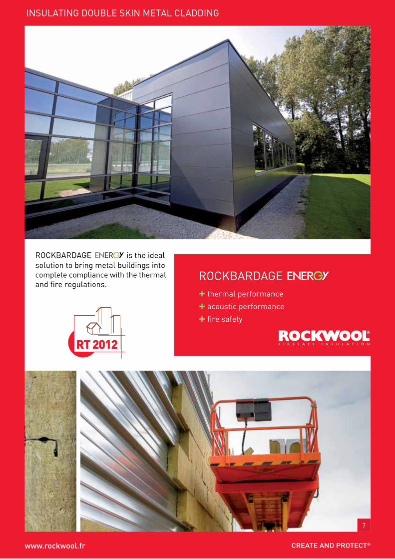
lE flocon 2 is stone wool in granules, used for the insulation of horizontal loft spaces by manual spreading using a rake.
tHERMAL PERFoRMAnCE
REFEREnCES, PACkIng
tECHnICAL CHARACtERIStICS
ADVAntAgES
LE fLoCon 2
Reaction to fire lE flocon 2 is incombustible; consequently it does not contribute to the development of the fire (Euroclass A1).
lnE-l050934 classification report available on www.rockwool.fr.
FIRE SAFEty
Ideal for renovation of horizontal lofts
pALLEtS SoLd In 2S
Desired thermal resistance R (m2.k/w)
thickness to be
spread (mm)
covering power
(kg/m2)
number of m2 covered
per bag
number of bags for
100 m2
2.00 75 3.70 6.80 14.7
2.50 95 4.60 5.40 18.4
3.00 115 5.60 4.50 22.0
3.50 130 6.50 3.90 25.7
4.00 150 7.40 3.40 29.4
4.50 170 8.30 3.00 33.0
5.00 185 9.20 2.70 36.7
5.50 205 10.10 2.50 40.4
6.00 225 11.10 2.30 44.0
6.50 240 12.00 2.10 47.7
7.00 260 12.90 1.90 51.4
7.50 280 13.80 1.80 55.1
weight characteristics performance
Reaction to fire (Euroclass) A1
nominal density (kg/m3) 50
Health labelling A
Reference packingnumber of
bags / palletnumber ofkg / pallet
tautliner lorry kg /load (36 pallets) EAn code
129554 25 kg plastic bag 15 375 13,500 3 53731 0100313

19
InD
uSt
RIA
L B
uIL
DIn
gS
oFFI
CES
& P
uBL
IC B
uIL
DIn
gSM
uLt
I-u
nIt
Bu
ILD
Ing
SIn
gLE
FA
MIL
y H
ou
SES
19
InD
uSt
RIA
L B
uIL
DIn
gS
oFFI
CES
& P
uBL
IC B
uIL
DIn
gSM
uLt
I-u
nIt
Bu
ILD
Ing
SIn
gLE
fA
MIL
y H
ou
SES
InSuLAtIng HorIZontAL Loft SpACES / by MAnuAL SprEAdIng
APPLyIng HoRIzontAL LoFt InSuLAtIon By MAnuAL SPREADIng
Step 1: Preparing the work site
we recommend marking the desired insulation level by tracing the level to be obtained on the frames and gable walls.the bags must be taken up into the loft as required and placed on a strong rigid support (example: floor panel nailed onto the frames). the bags must never be placed on a light ceiling. the bags must be opened in this work zone.the condition of the floor and its ability to support the weight of the insulation must be verified (in particular for non-load bearing ceilings, plasterboard, panelling, etc.)
this technique only needs one person if they can carry 25 kg bags.
Step 2: Laying the insulation
the insulation must be placed between the frames or on the flat floor using a shovel then levelled with a rake to achieve the desired thickness. the insulation must not be compressed. Its application density corresponds to the natural density of implementation of this technique. In the case of a light ceiling take care not to create an overload on the ceiling. Do not pour more than 28 cm locally. In no case must the lE flocon 2 product be blown using a machine, which will damage it and not obtain the desired insulation.
Insulating an access hatch:
the access hatch for a horizontal loft space must be insulated by inserting a panel of insulation cut to the shape of the hatch (RockmuR type). the edge of the access hatch must be fitted with a rubber seal or equivalent to provide airtightness. the thermal resistance of the insulation used on the hatch must be equal to that of the rest of the loft space if it is situated above a heated room.
Special case where a floor is laid in an unused loft space to store objects or ease any movements:
when a partial or complete division surface (floor on joists, particle boards, circulation path, etc.) is placed above the insulation there is a risk of condensation. In particular on the underside of this surface if it has low permeability compared to the permeability of the lower layers comprising the floor before insulation (ceiling of the lower storey) and the insulation. A vapour barrier sheet must be laid on the ceiling before applying the insulation and 2 cm ventilation must be allowed between the insulation and the underside of the floor.
Step 3: End of work
this technique does not generate any insulation offcuts. only the packaging must be returned to a distributor providing collection of non-hazardous, non-inert wastes, to a waste recycling centre or building waste sorting centres.

20
www.rockwool.fr
20
www.rockwool.fr
rouLroCk krAft
stone wool rolls faced with a polyethylene kraft paper vapour barrier to be unrolled on a horizontal loft space floor board.
REFEREnCES, PACkIng
tECHnICAL CHARACtERIStICS
ADVAntAgES
rouLroCk krAft
Reaction to fire no determined performance (Euroclass f).use authorised in buildings open to the public (E.R.p - Etablissement Recevant du public) under article Am8 of the order of 6 october 2004 and its addition of 4 July 2007.
* no performance determined
FIRE SAFEty
CERtIFICAtES
ACERMI kEyMARk 02/015/001 008-sDg5-001
DoP cpR- Dop-fR-023
weight characteristics performance
thermal conductivity (w/m.k) 0.042 / 0.039
Reaction to fire (Euroclass) f*
nominal density (kg/m3) 21 to 26
thickness tolerance t1Dimensional stability under specified temperature and humidity conditions Ds(tH)
short term water absorption ws
Health labelling A+
ReferenceDimensions
l x w x t (mm)thermal resistance
(m².k/w)number
of units / packagesnumber of
m²/ packagenumber of
packages / palletnumber ofm²/ pallet
53435 8000 x 1200 x 60 1.40 1 9.60 18 172.80
53436 6000 x 1200 x 80 1.90 1 7.20 18 129.60
53437 5000 x 1200 x 100 2.35 1 6.00 18 108.00
59419 4000 x 1200 x 120 2.85 1 4.80 18 86.40
59420 3500 x 1200 x 140 3.30 1 4.20 18 75.60
63555 3000 x 1200 x 160 3.80 1 3.60 18 64.80
63479 2700 x 1200 x 180 4.25 1 3.24 18 58.32
74745 2200 x 1200 x 200 5.10 1 2.64 18 47.52
Quick to unroll on a flat floor
Density scale— +

21
InD
uSt
RIA
L B
uIL
DIn
gS
oFFI
CES
& P
uBL
IC B
uIL
DIn
gSM
uLt
I-u
nIt
Bu
ILD
Ing
SIn
gLE
FA
MIL
y H
ou
SES
21
InD
uSt
RIA
L B
uIL
DIn
gS
oFFI
CES
& P
uBL
IC B
uIL
DIn
gSM
uLt
I-u
nIt
Bu
ILD
Ing
SIn
gLE
fA
MIL
y H
ou
SES
InSuLAtIng HorIZontAL Loft SpACES / In roLLS
Step 1: preparing the work site Calculating the number of rolls
number of rolls = loft area (m2) x number of layers area of a roll (m2)
the packages can be taken up into the loft as needed or all at the same time if they can be placed on structures (frames or floors) and are not a hindrance during application. this technique only needs one person.
Step 2: Laying the insulationthe insulation must be placed between frames or on the flat floor with the vapour barrier arranged against the ceiling. the roll packages must only be opened in the loft.when laying between frames it is preferable to cut the tools to the spacing width before opening them. once opened the rolls unroll almost on their own. they must be positioned to provide perfect continuity of the insulating layer.they must be in contact with the gable walls and placed at the level of the undersides of the roof slope up to the bottom rails. the insulation must not be compressed in thickness because this will damage the ceiling facings or reduce the thermal performance of the product. between frames, check that the insulation is in good contact with the ceiling and that it actually passes under the frames.when laying in two or more layers the vapour barriers on the upper layers must be perforated or slashed.
storing objects on the insulation is not authorised. moving around on the insulation is prohibited. If movement becomes necessary for maintenance reasons, the insulation must be cleared from the path and put back in place after the work.
Insulating an access hatch:the access hatch for a horizontal loft space must be insulated by inserting a panel of insulation cut to the shape of the hatch. the edge of the access hatch must be fitted with a rubber seal or equivalent to provide airtightness. the thermal resistance of the insulation used on the hatch must be equal to that of the rest of the loft space if it is situated above a heated room.
Special case where a floor is laid in an unused loft space to store objects or ease any movements:when a partial or complete division surface (floor on joists, particle boards, circulation path, etc.) is placed above the insulation there is a risk of condensation. In particular on the underside of this surface if it has low permeability compared to the permeability of the lower layers comprising the floor before insulation (ceiling of the lower storey) and the insulation. A vapour barrier sheet must be laid on the ceiling before applying the insulation and 2 cm ventilation must be allowed between the insulation and the underside of the floor.
APPLICAtIon

22
www.rockwool.fr
22
www.rockwool.fr
roCkMur krAft
stone wool panel clad with polyethylene kraft paper vapour barrier, intended for insulation:• of all types of vertical walls between frames • all types of masonry internal partitions • furnished attics, to be fitted between studding or windows.
REFEREnCES, PACkIng
tECHnICAL CHARACtERIStICS
ACouStIC PERFoRMAnCE
ADVAntAgES
roCkMur krAft
Reaction to fire no determined performance (Euroclass f).use authorised in buildings open to the public (E.R.p - Etablissement Recevant du public) under article Am8 of the order of 6 october 2004 and its addition of 4 July 2007. test of standard 12.5 mm plaster board inner partition on
200 mm hollow block wall + 15 mm coating.
* no performance determined
FIRE SAFEty
CERtIFICAtES
weight characteristics performance
thermal conductivity (w/m.k) 0.037
Reaction to fire (Euroclass) f*
nominal density (kg/m3) 28 to 36
thickness tolerance t3Dimensional stability under specified temperature and humidity conditions Ds(tH)
short term water absorption ws
Rw (c;ctr) in db
RA RA,tr
200 mm hollow block wallcoated but uninsulated
55 (-1; -3)
54 52200 mm hollow block wall, coated and insulated with RockmuR kRAft thk. 100 mm
65 (-2; -9)
63 56
ReferenceDimensions
l x w x t (mm)thermal resistance
(m².k/w)number
of units / packagesnumber of
m²/ packagenumber of
packages / palletnumber ofm²/ pallet
72281 1350 x 600 x 45 1.20 14 11.34 12 136.08
72282 1350 x 600 x 60 1.60 12 9.72 12 116.64
72283 1350 x 600 x 75 2.00 10 8.10 12 97.20
72284 1350 x 600 x 100 2.70 8 6.48 12 77.76
72285 1350 x 600 x 120 3.20 6 4.86 12 58.32
Available thicknesses from 45 to 120 mm.
CSTB Tests: no. 30698/1
ACERMI kEyMARk 02/015/025 008-sDg5-025
DoP cpR- Dop-fR-028
Density scale— +

23
InD
uSt
RIA
L B
uIL
DIn
gS
oFFI
CES
& P
uBL
IC B
uIL
DIn
gSM
uLt
I-u
nIt
Bu
ILD
Ing
SIn
gLE
FA
MIL
y H
ou
SES
23
InD
uSt
RIA
L B
uIL
DIn
gS
oFFI
CES
& P
uBL
IC B
uIL
DIn
gSM
uLt
I-u
nIt
Bu
ILD
Ing
SIn
gLE
fA
MIL
y H
ou
SES
InSuLAtIng VErtICAL wALLS/IntErnAL pArtItIonS on frAMEwork or MASonry
Step 1: Supply to the work sitefor insulation using an internal panel on a frame or masonry the insulation packages, the internal facings, the frames and accessories must be stored in accordance with the recommendations from each manufacturer. for insulation, external storage is possible if the pallet packaging is in good condition. Individual packages must be stored inside the building.Installing insulation panels does not require any special tools.
Step 2: preparing the work siteIn all cases, the walls must be clean, sound and free from any trace of damp. watertightness must be provided by the external or internal coating even in the case of external insulation under cladding or under a coating.for an inner partition on a frame, its position will depend on the choice of construction mode and the desired insulation thickness. Dtu 25-41 recommends the dimensions of inner partitions with or without intermediate fixing to the support.
Step 3: Choice of construction method- Case no. 1: Inner partitions comprising single or double uprights without intermediate fixing to the supportthe uprights must be dimensioned to suit the height of the inner partition and their installation method (single or double).for a maximum 2.50 m high inner partition, the uprights must be inserted in the top and bottom rails every 60 cm either singly with m70/35 uprights or double with m48/50 uprights.constructing the inner partition without intermediate fixings allows improved acoustic and thermal performance.
Case no. 2: Inner partitions comprising single or double uprights with intermediate fixing to the supportfor 6 m maximum height inner partition, the minimum
m48/35 uprights must be placed every 60 cm and fixed to the support wall by metal supports a maximum of 1.50 m apart vertically.the metal supports must be fixed using fixings suited to the type of wall. Case no. 3: Inner partitions comprising furring with
clipped intermediate supportsthis case is limited to the construction of 2.70 m maximum height partitions in residential premises. the furring must be clipped into intermediate supports generally comprising two or three inseparable parts (a spacer to be inserted in horizontal furring fixed on the support wall or a spacer to be fixed directly into the wall, and a bridge to be inserted in vertical furring on the warm side, and fixed onto this spacer). Fixing top and bottom rails:
fix the top and bottom rails onto the carcass floor and ceiling at a distance from the wall to be lined greater than or equal to the insulation thickness used with the addition of any air gap depending on the wall type. the rails must be aligned with the plane of the furring, the facing and the internal backstop of the joinery.
APPLICAtIon “on VERtICAL WALLS”
upright Insulation (mm)min - max
max. height (m)
spacing 60 cm
single upright Double upright
m36/40 30 1.75 2.10
m48/3530 to 50
2.00 2.40
m48/50 2.15 2.55
m70/3530 to 70
2.50 3.00
m70/50 2.70 3.20
m90/3530 to 85
2.90 3.45
m90/50 3.10 3.70
m100/50 30 to 100 3.30 3.90

24
www.rockwool.fr
24
www.rockwool.fr
roCkMur krAft
Fixing intermediate supports:After installing the horizontal furring at mid-height of the wall and at 1 m 35 maximum from the floor, the spacers must be inserted every 60 cm maximum in the horizontal direction, taking the specific features of the wall into account.
Fixing vertical furring:clip the vertical furring into the spacers before or after fitting the insulation.
Case no. 4: Masonry inner partitionsDepending on the type of walls a device to retain a sufficient layer of air must be fixed onto the wall to be lined. for all other cases the inner partition must be mounted at a distance equal to the thickness of the insulation. the partition must not be linked to the wall to be lined and must be in contact with the insulation. Implementation is dictated by dtu 25-31 and the instructions of the manufacturer of the internal facing. for these 2 cases: the insulation is fitted in a single layer with thickness equal to the distance between the support wall and the internal face of the facing.
Step 4: Laying the insulationfor an inner partition on a frame:- If the frame backs against the wall the insulating panels
must be inserted vertically between the frame uprights, the insulation thickness must be less than or equal to the depth of the uprights. because of their 1350 mm format the superposition of 2 Rockwool panels is sufficient to reach the standard 2700 mm under ceiling height.
- If the frame is mounted at a distance from the wall by one of the 3 techniques presented in step 3, this distance will be determined so that the thickness of insulation placed between the wall and the uprights plus the thickness of the insulation inserted between the uprights allows the desired thermal resistance to be achieved. the thermal resistances of the insulating layers add together.
the panels must be inserted vertically between the uprights. Due to their rigidity, the Rockwool panels do not need any fixing. certain types of walls need a layer of air between the wall and the insulation, the rigidity of the Rockwool panels guarantees that the insulation will not expand into the air layer. However a spacer can be used on the support wall.the standard spacing between uprights is 600 mm, it corresponds to the width of the insulating panels. for 400 mm spacing cuts must be done cleanly with a saw through the whole thickness of the panel, the 200 mm offcuts must be retained to make up a 400 mm width.for a masonry inner partition, the insulation panels can be placed as the internal inner panel is assembled or even beforehand by fixing them to the support wall if this allows installation without an air layer.prior fixing can be done by plugging using 2 plugs with washers per panel or by bonding with adhesive mortar using 3 to 4 10 cm diameter blocks per panel.
25
InD
uSt
RIA
L B
uIL
DIn
gS
oFFI
CES
& P
uBL
IC B
uIL
DIn
gSM
uLt
I-u
nIt
Bu
ILD
Ing
SIn
gLE
FA
MIL
y H
ou
SES
25
InD
uSt
RIA
L B
uIL
DIn
gS
oFFI
CES
& P
uBL
IC B
uIL
DIn
gSM
uLt
I-u
nIt
Bu
ILD
Ing
SIn
gLE
fA
MIL
y H
ou
SES
InSuLAtIng furnISHEd AttICS
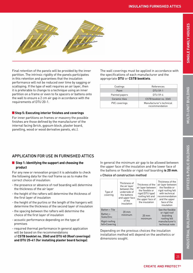
final retention of the panels will be provided by the inner partition. the intrinsic rigidity of the panels participates in this retention and guarantees that the insulation performance will not be reduced over time by sagging or scalloping. If the type of wall requires an air layer, then it is preferable to change to a technique using an inner partition on a frame or even to fix spacers or battens onto the wall to ensure a 2 cm air gap in accordance with the requirements of Dtu 20-1.
Step 5: Executing interior finishes and coveringsfor inner partitions on frames or masonry the possible finishes are those defined by the manufacturer of the internal facing (brick, gypsum block, plaster board, panelling, wood or wood derivative panels, etc.).
the wall coverings must be applied in accordance with the specifications of each manufacturer and the appropriate dtu or CStb booklets.
coatings References
paint Dtu 59-1
painted papers Dtu 59-4
ceramic tiles cstb booklet no. 3265
pvc coverings manufacturer's technical recommendation
Step 1: Identifying the support and choosing the product
for any new or renovation project it is advisable to check the following data for the roof frame so as to make the correct choice of insulation: - the presence or absence of roof boarding will determine
the thickness of the air layer- the height of the rafters will determine the thickness of
the first layer of insulation - the height of the purlins or the length of the hangers will
determine the thickness of the second layer of insulation- the spacing between the rafters will determine the
choice of the first layer of insulation- acoustic performance depending on the type of
premises- required thermal performance In general application
will be based on the recommendations of CStb booklet no. 3560 and dtu 40 (roof coverings) and dtu 25-41 (for installing plaster board facings).
In general the minimum air gap to be allowed between the upper face of the insulation and the lower face of the battens or flexible or rigid roof boarding is 20 mm. Choice of construction method
Depending on the previous choices the insulation installation method will depend on the aesthetics or dimensions sought.
APPLICAtIon FoR uSE In FuRnISHED AttICS
type ofcovering
thickness of the air layer between the underside of the battens
and upper face of the
insulation
thickness of the air layer between
the flexible or rigid (Dtu type) roofing felt and
the upper face of the insulation
thickness of the air layer between
the flexible or rigid roofing felt with technical
recommendation and the upper
face of the insulation
batten + tile20 mm
minimum 20 mm minimum
see the flexible or rigid roof
boarding roofing felt
manufacturer's technical note
batten + slate/Zinc
Rigid roofing felt+covering

26
www.rockwool.fr
26
www.rockwool.fr
roCkMur krAft
If there is a first layer of insulation it must be positioned between the rafters. the second must be positioned between the purlins, behind metal frames (furring) or between wooden frames (sleepers). Depending on the chosen thickness of insulation the facing forming the ceiling must be either continuous in front of the purlins or between them. for a roof frame in light frames the first and second layers must be positioned between the light frames.
Step 2: Installing metal hangersthe roof covering and all its accessories are considered to be installed, covered closure is provided. the metal hangers must be fixed onto the rafters before installing insulation in accordance with the manufacturer's specifications. the furring must be installed perpendicular to the rafters. the distances between the frame lines must be defined from the start according to the orientation of the internal facings: - 40 cm if installing plasterboard parallel to the furring (4
supports)- 60 cm if installing plasterboard perpendicular to the
furring.
Step 3: Installing the insulation In the case of a frame in timber sleepers, fix them perpendicular to the rafters with a spacing depending on the dimensions of the internal facing. Insert the panels to form the second layer of insulation. this must not be compressed in thickness.for a metal frame, for the 40 cm spacings (parallel installation), a hole must be cut right through the thickness of the panels to ease pinning into the hangers.for the 60 cm spacings (perpendicular installation), a 2-3 cm notch can be made in the edge of the panel to ease insertion.the furring can be put in place on hangers before installing the insulation to ease its retention.
Step 4: Insulating any false loftIn the case of a false loft, and with energy saving in mind, it is advisable to insulate the vertical walls and the loft space floor rather than the roof pitch so as not to "heat" this unused volume.the loft space floor can be insulated in rolls, panels or using loose material.vertical walls must be insulated in semi-rigid or rigid panels with identical performance to the pitch.for a false loft on a metal frame or industrial light frames, place the panels between the frames in one or two layers depending on the performance sought, arranging the vapour barrier towards the interior of the premises to be insulated.for example, for a partition block false loft, fix the semi-rigid panels in adhesive mortar or by plugging onto the inner partition.
Step 5: Applying finishestake care that the panels join correctly.check that the whole surface of the roof pitch is well insulated, including the edge, the bottom of the slope, on the gables and at the ceiling or ridge. the choice of rigid panels ensures that the pieces of panel are held at individual points.the panels must be cut cleanly with a saw or the Rockwool knife, increasing the dimension to be obtained by a few millimetres. l shaped cuts or holes in the insulation can be made in rigid panels.
27
InD
uSt
RIA
L B
uIL
DIn
gS
oFFI
CES
& P
uBL
IC B
uIL
DIn
gSM
uLt
I-u
nIt
Bu
ILD
Ing
SIn
gLE
FA
MIL
y H
ou
SES
27
InD
uSt
RIA
L B
uIL
DIn
gS
oFFI
CES
& P
uBL
IC B
uIL
DIn
gSM
uLt
I-u
nIt
Bu
ILD
Ing
SIn
gLE
fA
MIL
y H
ou
SES
InSuLAtIng furnISHEd AttICS
It is preferable to use a vapour barrier adhesive to make the joints between the panels and improve air tightness.If the vapour barrier is pierced or torn it must be repaired with a vapour barrier adhesive.
Step 6: Installing the ceilingfix the internal facings onto the metal or timber frame in accordance with the Dtu and their manufacturer's instructions, onto the inclined pitch and the vertical walls of the false loft.
Step 7: Internal coveringsthe finishing or covering work for internal walls must comply with the manufacturer's instructions for the products used

28
www.rockwool.fr
28
www.rockwool.fr
roCkMur nu & ALpHAroCk
RockmuR nu and AlpHARock are bare stone wool panels used for insulating all types of partitions between timber or metal uprights.
tECHnICAL CHARACtERIStICS
ADVAntAgES
roCkMur nu & ALpHAroCk
CERtIFICAtES
roCkMur nu ACERMI kEyMARk CE
02/015/021 008-sDg5-021 1163-cpD-0009
DoP cpR- Dop-fR-003
ALpHAroCk ACERMI kEyMARk CE
08/015/489 008-sDg5-489 1163-cpD-0229
DoP cpR- Dop-fR-019
performance
weight characteristics RockmuR nu AlpHARock
thermal conductivity (w/m.k) 0.037 0.034
Reaction to fire (Euroclass) A1 A1
nominal density (kg/m3) 28 to 36 70
semi-rigidity criteria AcERmI certified
AcERmI certified
thickness tolerance t3 t3Dimensional stability at specified temperature Ds(70,90)
Dimensional stability under specified temperature and humidity conditions Ds(tH)
short term water absorption ws ws
long term water absorption - wl(p)
water vapour transmission mu1 mu1
Health labelling A+ A
roCkMur nu the greatest range of thicknesses in the range.
ALpHAroCk Easy to cut due to the rigidity of the panel.
Density scale— +
Density scale— +
roCkMur nu
ALpHAroCk

29
InD
uSt
RIA
L B
uIL
DIn
gS
oFFI
CES
& P
uBL
IC B
uIL
DIn
gSM
uLt
I-u
nIt
Bu
ILD
Ing
SIn
gLE
FA
MIL
y H
ou
SES
29
InD
uSt
RIA
L B
uIL
DIn
gS
oFFI
CES
& P
uBL
IC B
uIL
DIn
gSM
uLt
I-u
nIt
Bu
ILD
Ing
SIn
gLE
fA
MIL
y H
ou
SES
InSuLAtIng VErtICAL wALLS on tHE InSIdE /pArtItIonS
RoCkMuR nuREFEREnCES, PACkIng
ALPHARoCkREFEREnCES, PACkIng
ReferenceDimensions
l x w x t (mm)
thermal resist-ance
(m².k/w)number
of units / packagesnumber of
m²/ packagenumber of
packages / palletnumber ofm²/ pallet
72275 1350 x 600 x 45 1.20 14 11.34 12 136.08
72276 1350 x 600 x 60 1.60 12 9.72 12 116.64
72277 1350 x 600 x 75 2.00 10 8.10 12 97.20
72278 1350 x 600 x 100 2.70 8 6.48 12 77.76
72279 1350 x 600 x 120 3.20 6 4.86 12 58.32
72280 1350 x 600 x 140 3.75 5 4.05 12 48.60
ReferenceDimensions
l x w x t (mm)
thermal resist-ance
(m².k/w)number
of units / packagesnumber of
m²/ packagenumber of
packages / palletnumber ofm²/ pallet
53452 1350 x 600 x 30 0.85 10 8.10 16 129.60
53453 1350 x 600 x 40 1.15 10 8.10 12 97.20
53454 1350 x 600 x 50 1.45 6 4.86 16 77.76
53455 1350 x 600 x 60 1.75 5 4.05 16 64.80
55972 1350 x 600 x 80 2.35 5 4.05 12 48.60
63563 1350 x 600 x 100 2.90 3 2.43 16 38.88
30
www.rockwool.fr
30
www.rockwool.fr
roCkMur nu & ALpHAroCk
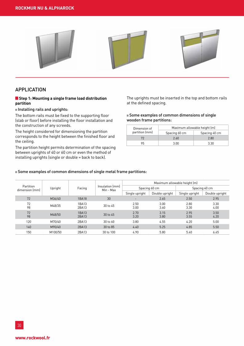
Step 1: Mounting a single frame load distribution partition Installing rails and uprights:
the bottom rails must be fixed to the supporting floor (slab or floor) before installing the floor installation and the construction of any screeds.the height considered for dimensioning the partition corresponds to the height between the finished floor and the ceiling.the partition height permits determination of the spacing between uprights of 40 or 60 cm or even the method of installing uprights (single or double = back to back).
the uprights must be inserted in the top and bottom rails at the defined spacing.
Some examples of common dimensions of single wooden frame partitions:
Some examples of common dimensions of single metal frame partitions:
APPLICAtIon
Dimension ofpartition (mm)
maximum allowable height (m)
spacing 60 cm spacing 40 cm
72 2.60 2.80
95 3.00 3.30
partition dimension (mm) upright facing Insulation (mm)
min - max
maximum allowable height (m)
spacing 60 cm spacing 40 cm
single upright Double upright single upright Double upright
72 m36/40 1bA18 30 - 2.65 2.50 2.95
72 98 m48/35 1bA13
2bA13 30 to 45 2.50 3.00
3.00 3.60
2.80 3.30
3.30 4.00
72 98 m48/50 1bA13
2bA13 30 to 45 2.70 3.20
3.15 3.80
2.95 3.55
3.50 4.20
120 m70/40 2bA13 30 to 60 3.80 4.55 4.20 5.00
140 m90/40 2bA13 30 to 85 4.40 5.25 4.85 5.50
150 m100/50 2bA13 30 to 100 4.90 5.80 5.40 6.45

31
InD
uSt
RIA
L B
uIL
DIn
gS
oFFI
CES
& P
uBL
IC B
uIL
DIn
gSM
uLt
I-u
nIt
Bu
ILD
Ing
SIn
gLE
FA
MIL
y H
ou
SES
31
InD
uSt
RIA
L B
uIL
DIn
gS
oFFI
CES
& P
uBL
IC B
uIL
DIn
gSM
uLt
I-u
nIt
Bu
ILD
Ing
SIn
gLE
fA
MIL
y H
ou
SES
InSuLAtIng VErtICAL wALLS on tHE InSIdE /pArtItIonS
Step 2: Installing the insulationone face of the partition must be fixed before starting to fit the insulation.the bare rigid and semi-rigid panels must be selected so as not to exert pressure on the facings, consequently a thickness less than or equal to the depth of the uprights is recommended.In the case of 60 cm spacing with single uprights, fitting the panels is done by inserting the edge of the panel into the upright until it is completely housed in the bottom of the upright. then placing the opposite edge against the facing in place. take care to limit acoustic bridges in the bottom and top parts by fitting well jointed panels.In the case of 60 cm spacing with double uprights:- the semi-rigid panels are fitted by inserting an edge in
the first upright then inserting the rest of the panel in the opposite upright by sideways bending of the opposite edge.
- Rigid panels are fitted by cutting each panel in 2 to obtain 30 cm wide boards. Each board must be inserted in the opposing uprights then flattened onto the central part of the space to be insulated.
In the case of 40 cm spacing with single or double uprights, semi-rigid panels must first be cut to 40 cm wide.the semi-rigid panels are fitted by inserting an edge in the first upright then inserting the rest of the panel in the opposite upright by sideways bending of the opposite edge.fitting of rigid panels is not commonly used because it necessitates additional cuts.Rockwool rigid and semi-rigid panels comply with the requirements of Dtu 25-41 aiming to guarantee the behaviour of the insulation over time. the AcERmI certification of the semi-rigidity criterion demonstrates proof of product compliance to Dtu 25-41.
Step 3: fitting the electrical equipmentIf the insulation thickness is equal to the depth of the uprights any electrical ducts must be placed on feet under the insulation or by grooving the insulation so as to limit acoustic bridges. fitting insulation in 2 layers (2 x 30 mm instead of 1 x 60 mm) ensures insulation continuity at the equipment and avoids cutting any grooves. with the aim of avoiding acoustic bridges, rigid panels must be bored with a hole saw, or a knife can be used to make a square or round recess in the panel at switch boxes and sockets. It is advisable to replace these pieces of wool behind the boxes.If the insulation thickness is sufficiently less than the uprights, electrical ducts can run in front of the insulation.
Step 4: fitting the second face and executing finishesthe plasterboard must be installed, fixed and jointed in accordance with the requirements of dtu 25-41 and the plasterboard manufacturer's technical recommendations or specification guides .the same technical recommendations and specification guides describe the other possible assemblies (alternate frame, separate frame, special points, great heights, internal reinforcements, etc.).Quantities of accessories (joint strips, fastenings, rails, uprights, etc.) must be used according to the plasterboard manufacturer's specifications.our acoustic brochure and the www.rockwool.fr Internet site summarise all the acoustic tests made on metal frame partitions and plasterboard facings or fibre cement board and wood frame and facing partitions.
Step 5: End of workInsulation offcuts and packaging must be returned to a distributor providing collection of non-hazardous inert wastes (for the insulation) and non hazardous non-inert wastes (for the packaging), to a waste recycling centre or building waste sorting centres.

32
www.rockwool.fr
32
www.rockwool.fr
roCkwooL 001
ADVAntAgES
roCkwooL 001
Excellent additional insulation for existing uninsulated structures, without removing the internal facing.
Rockwool 001 is stone wool in granules used for filling double masonry or timber wall internal walls by blowing in from the inside or outside face.
REFEREnCES, PACkIng
CERtIFICAtES
tECHnICAL RECoMMEnDAtIon DoP 20/04-38 cpR- Dop-fR-002 (being renewed)
tECHnICAL CHARACtERIStICS
weight characteristics performance
Reaction to fire (Euroclass) A1
nominal density (kg/m3) 70
Health labelling A
Reaction to fire Rockwool 001 is incombustible; consequently it does not contribute to the development of the fire (Euroclass A1).lnE-l050934 classification report available on www.rockwool.fr.
FIRE SAFEty
Reference packingnumber of
bags / palletnumber ofkg / pallet
tautliner lorry kg / load (18 pallets) EAn code
57223 25 kg plastic bag 30 750 13,500 3 53731 0038708
cavity width (mm)
Declared thermal resistance R (m2 k/w)
minimum rateof use of
bags for 100 m2
30 0.80 7.20
40 1.05 9.60
50 1.30 12.00
60 1.60 14.40
70 1.85 16.80
80 2.10 19.20
90 2.40 21.60
100 2.65 24.00
110 2.90 26.40
120 3.20 28.80
130 3.45 31.20
140 3.70 33.60
150 4.00 36.00
160 4.25 38.40
170 4.50 40.80
180 4.80 43.20
190 5.05 45.60
200 5.30 48.00
Thicknesses from 110 to 200 mm are not covered by the Technical Recommendation.
tHERMAL PERFoRMAnCE
33
InD
uSt
RIA
L B
uIL
DIn
gS
oFFI
CES
& P
uBL
IC B
uIL
DIn
gSM
uLt
I-u
nIt
Bu
ILD
Ing
SIn
gLE
FA
MIL
y H
ou
SES
33
InD
uSt
RIA
L B
uIL
DIn
gS
oFFI
CES
& P
uBL
IC B
uIL
DIn
gSM
uLt
I-u
nIt
Bu
ILD
Ing
SIn
gLE
fA
MIL
y H
ou
SES
InSuLAtIng VErtICAL HoLLow wALLS
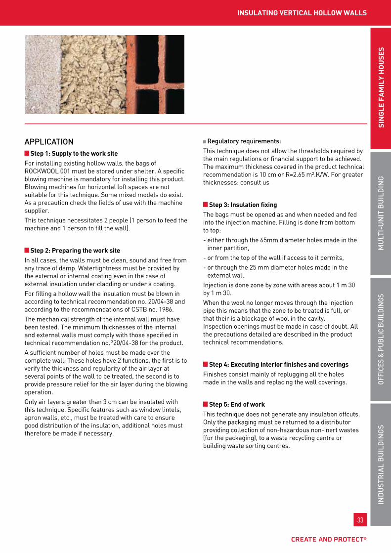
APPLICAtIon Step 1: Supply to the work site
for installing existing hollow walls, the bags of Rockwool 001 must be stored under shelter. A specific blowing machine is mandatory for installing this product. blowing machines for horizontal loft spaces are not suitable for this technique. some mixed models do exist. As a precaution check the fields of use with the machine supplier.this technique necessitates 2 people (1 person to feed the machine and 1 person to fill the wall).
Step 2: preparing the work siteIn all cases, the walls must be clean, sound and free from any trace of damp. watertightness must be provided by the external or internal coating even in the case of external insulation under cladding or under a coating.for filling a hollow wall the insulation must be blown in according to technical recommendation no. 20/04-38 and according to the recommendations of cstb no. 1986.the mechanical strength of the internal wall must have been tested. the minimum thicknesses of the internal and external walls must comply with those specified in technical recommendation no.°20/04-38 for the product.A sufficient number of holes must be made over the complete wall. these holes have 2 functions, the first is to verify the thickness and regularity of the air layer at several points of the wall to be treated, the second is to provide pressure relief for the air layer during the blowing operation.only air layers greater than 3 cm can be insulated with this technique. specific features such as window lintels, apron walls, etc., must be treated with care to ensure good distribution of the insulation, additional holes must therefore be made if necessary.
Regulatory requirements:this technique does not allow the thresholds required by the main regulations or financial support to be achieved. the maximum thickness covered in the product technical recommendation is 10 cm or R=2.65 m².k/w. for greater thicknesses: consult us
Step 3: Insulation fixingthe bags must be opened as and when needed and fed into the injection machine. filling is done from bottom to top:- either through the 65mm diameter holes made in the
inner partition,- or from the top of the wall if access to it permits,- or through the 25 mm diameter holes made in the
external wall.Injection is done zone by zone with areas about 1 m 30 by 1 m 30.when the wool no longer moves through the injection pipe this means that the zone to be treated is full, or that their is a blockage of wool in the cavity. Inspection openings must be made in case of doubt. All the precautions detailed are described in the product technical recommendations.
Step 4: Executing interior finishes and coveringsfinishes consist mainly of replugging all the holes made in the walls and replacing the wall coverings.
Step 5: End of workthis technique does not generate any insulation offcuts. only the packaging must be returned to a distributor providing collection of non-hazardous non-inert wastes (for the packaging), to a waste recycling centre or building waste sorting centres.

34
www.rockwool.fr
34
www.rockwool.fr
roCkSoL ExpErt
ADVAntAgES
roCkSoL ExpErt
Reaction to fireRockcAlm ExpERt is incombustible; consequently it does not contribute to the development of the fire (Euroclass A1).
FIRE SAFEty
CERtIFICAtES
guaranteed acoustic performance, high mechanical strength. for all types of premises with working loads < 500 kg/m2.
ACouStIC PERFoRMAnCE
tECHnICAL CHARACtERIStICS
A CTBA tests: series no. IBC/PHY/2162/8b CTBA tests: series no. 03/PC/PHY/2162/10
test under floating screed (Dtu 26.2) screed thk. 40 mm, slab thk. 140 mm.
systemsRw (c;ctr) in db
Δl in dbRA RA,tr
uninsulated slab without floating floor55 (-3; -7)
52 48
A slab insulated with Rocksol ExpERtthk. 15 mm and 40 mm floating floor
57 (-3; -8)18
54 49
b slab insulated with Rocksol ExpERtthk. 40 mm and 40 mm floating floor
59 (-3; -8)21
56 51
bare single density stone wool panel, used for thermal and acoustic insulation of floating screeds for high load bottom floors.
ACERMI kEyMARk 07/015/449 008-sDg5-449
CE DoP 1163-cpD-0179 cpR- Dop-fR-012
weight characteristics performance
thermal conductivity (w/m.k) 0.038
Reaction to fire (Euroclass) A1
nominal density (kg/m3) 120 to 150
thickness tolerance t5Dimensional stability at specified temperature Ds(70,90)
compression sc2 a3 A ch
long term water absorption wl(p)
water vapour transmission mu1
Health labelling A
Density scale— +

35
InD
uSt
RIA
L B
uIL
DIn
gS
oFFI
CES
& P
uBL
IC B
uIL
DIn
gSM
uLt
I-u
nIt
Bu
ILD
Ing
SIn
gLE
FA
MIL
y H
ou
SES
35
InD
uSt
RIA
L B
uIL
DIn
gS
oFFI
CES
& P
uBL
IC B
uIL
DIn
gSM
uLt
I-u
nIt
Bu
ILD
Ing
SIn
gLE
fA
MIL
y H
ou
SES
InSuLAtIng fLoorS/ConCrEtE fLoAtIng fLoor
REFEREnCES, PACkIng
ReferenceDimensions
l x w x t (mm)
thermal resistance
(m².k/w)number of
panels/ palletnumber of
m²/ package
number ofpackages /
palletnumber ofm²/ pallet
minimum quantity
62577 1200 x 600 x 15 0.35 20 14.40 8 115.20 -
64438 1200 x 600 x 30 0.75 6 4.32 14 60.48 -
63643 1200 x 600 x 40 1.05 5 3.60 12 43.20 -
62576 1200 x 600 x 50 1.30 4 2.88 12 34.56 -
62578 1200 x 600 x 60 1.55 3 2.16 14 30.24 -
62575 1200 x 600 x 70 1.80 3 2.16 12 25.92 22 pallets
62579 1200 x 600 x 80 2.10 3 2.16 10 21.60 -
62574 1200 x 600 x 90 2.35 2 1.44 14 20.16 22 pallets
62581 1200 x 600 x 100 2.60 2 1.44 12 17.28 20 pallets
APPLICAtIon Step 1: Identifying the support and choosing the product
for any new or renovation project it is advisable to check the following data for the floor so as to make the correct choice of insulation:- verification of allowable support- Acoustic performance depending on the type of adjacent premises- target thermal performance (type of premises below)- Heated floor…the technique of applying insulation under a floating floor allows thermal and acoustic insulation of bottom or intermediate floor screeds with or without a floor heating system.Application is dictated by dtu 26-2 and 52-1 and the technical recommendations from manufacturers of non-traditional screeds.In the case of heated floors, the different possible applications are dictated by dtu 65-7, 65-10 and 65-14 as well as in CStb booklet no. 3606and in the floor heating system manufacturer's technical recommendations.the application of class SC1 or SC2 insulating sub-layers is only permitted in low load premises as specified by dtu 26-2 and 52-1.
In the concrete floating floor technique case the support must be free from deposits, waste, or other materials arising from the work of the different trades and must be flat to dtu 26-2 and 52-1 type I or II support.
2 m rule 20 cm rule
type I support 5 mm 1 mm
type II support 7 mm 2 mm
the load capacity of the support should be checked beforehand by the building owner and take account of the self weight of the screed, self levelling screed and / or any covering.the drying times indicated by the support supplier or stated in dtu 26-2 and 52-1 must be complied with. these times only concern low load premises covered for the application of insulating sub-layers.
Reinforced concrete slab 1 month
ground 2 weeks
self levelling screed 24 h
Step 2: preparing the work sitepallets may be supplied to the site and can be store outside for several weeks subject to the packaging being in good condition.

36
www.rockwool.fr
36
www.rockwool.fr
roCkSoL ExpErt
Step 12: End of workpedestrian traffic (without heavy objects or scaffolding) on the floating concrete floor can only take place after 3 weeks in accordance with dtu 26-2 and 52-1 or according to the time provided by the concrete floating floor supplier. Definitive commissioning occurs after 5 weeks according to dtu 26-2 and 52-1.
Appendix: Special case of calcium sulphate based screeds or so called anhydrite screeds (according to CStB booklet no. 3578):the conditions necessary for application of the concrete floating floor are as follows:• building closed and covered, glazing fitted (or bays
closed with hermetically-sealed sheets);• no risk of air currents for at least 24 hours• apartment separating partitions completed,
as well as masonry distribution partitions (> 150 kg/ml) and linings;
• plumbing and heating installations checked for leaks by the heating specialist;
• support and atmosphere temperature between 5 °C and 30 °c without risk of frost or excessive heat (> 30 °c) in the premises;
• no fear of risk of excessive rehumidification in the premises;
• no direct exposure to sunlight (cover windows) for at least 24 hours.
Special precautions:A polyethylene film must be installed in all cases where there is a risk of mortar penetrating the insulation or the joints. careful caulking of the insulation is required, given the fluidity of the screed. In order to avoid penetration of mortar under the separation sheet, lift the polyethylene
film on the edges of the walls or use flap strips bonded onto the insulation.If the joints are open or the insulation damaged (broken corners, etc.), plug with expanding foam. Maximum recommended thicknesses:
the maximum permitted thickness is 6 cm, except in the case of a heated screed, where the maximum thickness is 7 cm.
Minimum embedding layer thickness above heating tubes:
type A floor type c floor
sc2 a insulation 30 mm pRoHIbItED
sc2 b insulation pRoHIbItED pRoHIbItED
Recommendations for pouring the concrete floating floor:the screed is usually poured in one spread. In cases where the fastening systems do not permit floating up of the heating pipes to be avoided, it is necessary to pour in two passes, as follows:- the mortar is poured up to the upper edge of the heating
pipes. this preliminary layer is simply drawn over using the finishing broom or levelling bar.
- three days after pouring at the latest, the preliminary layer should be lightly moistened and surface scoured with a broom. the thickness gauges are adjusted and the second pass poured.
moderate pedestrian movement is possible 24 hours after pouring. Do not use stepladders, ladders or scaffolding without a spreader plate.

37
InD
uSt
RIA
L B
uIL
DIn
gS
oFFI
CES
& P
uBL
IC B
uIL
DIn
gSM
uLt
I-u
nIt
Bu
ILD
Ing
SIn
gLE
FA
MIL
y H
ou
SES
37
InD
uSt
RIA
L B
uIL
DIn
gS
oFFI
CES
& P
uBL
IC B
uIL
DIn
gSM
uLt
I-u
nIt
Bu
ILD
Ing
SIn
gLE
fA
MIL
y H
ou
SES

contributing to sustainable townsthe wide choice of Rockwool solutions contributes to designing a sustainable town with housing forming part of a process of improving performance and residents comfort.
38
www.rockwool.fr
InD
uSt
RIA
L B
uIL
DIn
gS
oFFI
CES
& P
uBL
IC B
uIL
DIn
gSM
uLt
I-u
nIt
bu
ILd
Ing
sIn
glE
fA
mIl
y H
ou
sEs

39
��RoCkWooL solutions for multi-unit housing
Inaccessible flat roof
Rock up b+ souDAblE Rock up b+ nu Rock up c nu Rock up c souDAblE
Horizontal lofts
RoulRocklE flocon 2
Furnished attics
RockmuR kRAft
Internal walls
RockmuR kRAft RockmuR nu AlpHARock
Floors over parking areas
RockfEu coffRAgE RockfEu REI RsD RAngE
External walls
REDAir systEm EcoRock unDER coAtIng RockfAçADE RockglAcE
Heating system
Domestic hot water Rockwool 800/835Rockwool 133 (Ef)
Ventilation systems and pipework / Fire stop protection conlIt DuctRock conlIt 150 u conlIt fIx conlIt pEnEtRAtIon boARD
roofSlE flocon 2 20 RoulRock kRAft 22 RockmuR kRAft 24 Rock up b+ nu 42 Rock up c nu 44 Rock up b+ souDAblE 78 Rock up c souDAblE 80
wALLSRockmuR kRAft 24 RockmuR nu AnD AlpHARock 30 REDAIR systEm 48 RockfAçADE 58 RockglAcE 59 EcoRock 62
fLoorSRocksol ExpERt 36 RockfEu coffRAgE 68 RockfEu REI RsD RAngE 72
HVACRockwool 800 84 Rockwool 835 86 Rockwool 133 (Ef) 88 conlIt 150 u 126 conlIt pEnEtRAtIon boARD 128 conlIt fIx 129 conlIt DuctRock 130
Floors under floating slabs
Rocksol ExpERt

40
www.rockwool.fr
40
www.rockwool.fr
Rock up b+ nu is a direct support panel for inaccessible roof waterproof coverings on load bearing elements or masonry with slope greater than or equal to 0% and lightweight concrete with slope greater than 1%.
roCk up b+ nu LArgE forMAtDensity scale
— +double density
REFEREnCES, PACkIng
the product +: - site productivity format.- Incombustible, safety.- Dimensional stability.- use without separating felt.- High acoustic performance.
tECHnICAL CHARACtERIStICS
CERtIFICAtES
ACERMI kEyMARk 13/015/817 008-sDg5-817
Etn DoP EAD9235/1 socotEc cpR- Dop-fR-045
ReferenceDimensions
l x w x t (mm)
Resistanceresistance
(m2.k/w)
number of m2/
package
number of panels/
pallet
number of m2/pallet
tautliner lorry m²/ load
(44 pallets)minimum
Quantity EAn codes
122034 1200 x 1000 x 50 1.25 3.60 8 28.80 1,497.60 - 3 53731 0098280
121805 1200 x 1000 x 60 1.50 3.60 7 25.20 1,310.40 - 3 53731 0097934
121806 1200 x 1000 x 70 1.75 3.60 6 21.60 1,123.20 - 3 53731 0097941
121808 1200 x 1000 x 80 2.05 2.40 8 19.20 998.40 - 3 53731 0097958
121809 1200 x 1000 x 90 2.30 2.40 7 16.80 873.60 - 3 53731 0097965
121810 1200 x 1000 x 100 2.55 2.40 6 14.40 748.80 - 3 53731 0097972
121812 1200 x 1000 x 110 2.80 2.40 5 12.00 624.00 - 3 53731 0097989
121813 1200 x 1000 x 120 3.05 2.40 5 12.00 624.00 - 3 53731 0097996
121827 1200 x 1000 x 130 3.30 2.40 4 9.60 499.20 - 3 53731 0098009
121830 1200 x 1000 x 140 3.55 2.40 4 9.60 499.20 - 3 53731 0098016
121831 1200 x 1000 x 150 3.80 2.40 4 9.60 499.20 - 3 53731 0098023
121833 1200 x 1000 x 160 4.10 2.40 4 9.60 499.20 - 3 53731 0098030
Reaction to fire A1
thermal conductivity (w/m.k) 0.039
thickness 50 mm ≥ 60 mm
nominal density of lower layer (kg/m3) 150 135
nominal density of upper layer (kg/m3) 210
thickness tolerance t5Dimensional stability in the specified temperature and humidity conditions Ds (70,90)
compression stress cs (10/y) 50
compressibility class (uEAtc) class b / deformation ≤ 5 % under test load of 20 kpa
tension strength perpendicular to the faces tR15
point load pl (5) 500
long term partial immersion water absorption wl (p)
water vapour transmission mu1
long term partial immersion water absorption ws
roCk up b+ nu

41
InD
uSt
RIA
L B
uIL
DIn
gS
oFFI
CES
& P
uBL
IC B
uIL
DIn
gSSI
ng
LE F
AM
ILy
Ho
uSE
SM
uLt
I-u
nIt
Bu
ILD
Ing
41
InD
uSt
RIA
L B
uIL
DIn
gS
oFFI
CES
& P
uBL
IC B
uIL
DIn
gSM
uLt
I-u
nIt
bu
ILd
Ing
SIn
gLE
FA
MIL
y H
ou
SES
APPLICAtIon oF RoCk uP B+ nu
CondItIonS of uSEthe Rock up b+ nu panels are laid on the vapour barrier, either free or fixed according to the technical file.
the waterproofing covering is applied either separately under added heavy duty protection, or mechanically fixed with visible step Resistant fixings.
gEnErALto avoid damage to the panels due to frequent passage during work, they must be covered with a rigid protection, for example a wooden decking. the packages should be opened as close as possible to the installation location, to avoid the panels being damaged or becoming damp.
A panel must never be used if it is damp inside. the surface accepting the panels must be dry.
the panels shall be covered by the first waterproofing layer as soon as they are laid.
AppLyIng tHE VApour bArrIErthe specifications of nf p 84-204-1 (ref. Dtu 43.1), or those of the technical Application Documents for the coverings, must be complied with.
AppLICAtIon of InSuLAtIng pAnELSRock up b+ nu panels are laid with the marked face upwards.
Rock up b+ nu panels are laid in a 50 to 190 mm thick layer or as a second layer on a first layer of Rock up b+ nu or as a first layer under a second layer of Rock up b+ souDAblE.
the panels are laid in a chequered pattern, joined, and fixed according to the provisions described below.
Depending on the case, Rock up b+ nu could be: - laid loose - fully EAc (Hot Applied coating) bonded - fully bonded, cold with fIx-up 284 or doubLE up
(for more information, refer to the fIx-up 284 or DoublE up technical datasheet).
special case of curved slopes.
the dimensions of the panels are those defined in Dtu 43.1, according to the radius of curvature (R) of the roof:
– l ≤
load bearing component slope (%)
coverings subject to technical Recommendation
Heavy duty loose protection self protection
separate covering mechanically fixed covering
masonry (1)0 to 5 fIt class " 4"
l3 and according to techR for the covering > 5 -
Autoclaved lightweight concrete (2)
1 to 5 fIt class " 4"
> 5 -
l3: static puncture resistance (cstb booklet 2358)fIt class " ": puncture resistance (nf p 84-352) of waterproof covering (specific technical Recommendations).(1) According to standard nf p 84-204 and nf p 84-205 (Dtu 43.1 and Dtu 43.2) and technical Recommendations(2) According to cstb booklet 2092 of october 1987 and technical Recommendationsthe greyed out boxes correspond to excluded uses.
InACCESSIbLE roofS
the total thickness must not exceed 260 mm
InSuLAtIng ConCrEtE fLAt roofS

42
www.rockwool.fr
42
www.rockwool.fr
roCk up C nu
ADVAntAgES
DIMEnSIonS
roCk up C nu
Rock up c nu is a non load bearing insulation panel forming a direct support for waterproof coverings on flat and inclined roofs in accordance with Dtu 43.1:- inaccessible flat roofs*, including walkways,- equipment flat roofs and equipment zones**, excluding
platform tracks.- green flat roofs (ttv) complying with the ttv
professional rules from the csfE***.- photo-voltaic flat roofs
*Inaccessible roofs are roofs for which traffic is limited to their maintenance only.** Equipment roofs and equipment zones are roofs are roofs where traffic is due to the presence of equipment or installations needing frequent maintenance visits.*** Can be used on extensive or semi-extensive green flat roofs, with grade "4" root resistant waterproof coating, usage described in the coating specific AT (Technical Recommendation) or DTA.
FIELD oF APPLICAtIon
can be used in equipment zones and green and photovoltaic flat roofs
the higher density part of the panels allows: - easier application of overlapping waterproof
covering joints - improved resistance to frequent passage
Avoids the use of a separating film thermal and acoustic performance Reaction to fire: Euroclass A1 (incombustible) Dimensional stability Rot proof
l. 1200 mm x w. 1000 mm l. 1200 mm x w. 1000 mm
MECHAnICAL CHARACtERIStICS
weight characteristics
values for Rock up c nu
single density double density
thickness (mm) 50 to 60 70 to 160
top face density(thk. ≈15 mm) (kg/m3) - 230 (average)
nominal density (kg/m3) 175 (average) 165 (average)
compressibility class (uEAtc) class c
compression stress at 10% ≥ 70 kpa
bare stone wool insulating panel, whose special feature is an increased density upper surface (from 70 mm thickness). this face can be marked to allow it to be positioned.
tHERMAL RESIStAnCE* AcERmI certificate no. 03/015/285 for thicknesses 50 to 60 mm (single density) AcERmI certificate no. 02/015/045 for thicknesses 70 to 160 mm (double density)
thk. (mm) 50 60 70 80 90 100 110 120
R (m2.k/w) 1.15 1.40 1.75 2.05 2.30 2.55 2.80 3.05
thk. (mm) 130 135 140 145 150 155 160
R (m2.k/w) 3.30 3.45 3.55 3.70 3.80 3.95 4.10
Minimum quantity: refer to the current price list.The black box shows the safe value corresponding to the RT 2005 regulatory minimum.
CERtIFICAtE
DtA DoP 5/12-2295 cpR- Dop-fR-032
Density scale— +

43
InD
uSt
RIA
L B
uIL
DIn
gS
oFFI
CES
& P
uBL
IC B
uIL
DIn
gSSI
ng
LE F
AM
ILy
Ho
uSE
SM
uLt
I-u
nIt
Bu
ILD
Ing
43
InD
uSt
RIA
L B
uIL
DIn
gS
oFFI
CES
& P
uBL
IC B
uIL
DIn
gSM
uLt
I-u
nIt
bu
ILd
Ing
SIn
gLE
FA
MIL
y H
ou
SES
InSuLAtIng ConCrEtE fLAt roofS
linear thermal expansion coefficient: 2 x 10-6.c-1.Residual deformation at 20° c: negligible.Dimensional variation at ambient temperature of 20 °c between 65 and 80 % RH: - longitudinal direction< 1 mm/m - transverse direction < 1 mm/mlow sensitivity to temperature and humidity variations.thickness expansion ≤ 5% (average 2 %).water absorption with full immersion 11 to 12% after 24h at 20 °c after 7 days and saturation. Return to initial weight in 48 hrs.
DIMEnSIonAL StABILIty
APPLICAtIon Inaccessible roofs
walkways
Heavy duty loose protection self protection
load bearing component slope (%) covering subject to DtA* Asphalt
covering subject to DtA* bonded using EAc (Hot
Applied coating) or independent
covering subject to DtA*bonded using EAc (Hot
Applied coating)
mechanically fixed covering (3)
masonry (1)0 to 5 According to covering
DtA or (4) fIt class "I4" fIt class:"I4" in single layer
system"I4" in double layer
system
l3 and according to DtA* for the covering
> 5 - -
Autoclaved lightweight concrete (2)
1 to 5 - fIt class "I4"
> 5 - -
Heavy duty loose protection self protection
load bearing component slope (%) covering subject to DtA* Asphalt
covering subject to DtA* bonded using EAc (Hot
Applied coating) or independent
covering subject to DtA*bonded using EAc (Hot
Applied coating)
mechanically fixed covering (3)
masonry (1)0 to 5 According to covering
DtA or (4) fIt class "I4"fIt class:
"I4" for single or double layer system
l4 and according to DtA* for the covering
> 5 - -
Autoclaved lightweight concrete (2)
1 to 5 - fIt class "I4"
> 5 - -
L3: Static puncture resistance (CSTB booklet 2358). FIT class "I ": Puncture resistance (NF P 84-352) of waterproof covering (specific DTA*).(1) To standards NF P 84-204 and NF P 84-205 (DTU 43.1 and DTU 43.2) and DTA*(2) According to CSTB booklet 2192 of October 1987 and DTA*(3) With Step Resistant fastening assemblies(4) Covering with type 5 Bitumen +15 (AP1+AS1), slope ≤ 3 %, in accordance with standard NF P 84-204-1-1 (DTU 43.1)*DTA: Document Technique d’Application (Technical Application Document) or specific Avis Technique (Technical Recommendation)The empty boxes correspond to excluded uses.

44
www.rockwool.fr
44
www.rockwool.fr
Extensive or semi-extensive green flat roofs
Root resistant coverings for garden flat roof subject to DtA*
load bearing component slope (%) (2) separate covering (1) bonded covering
masonry (1) 0 to 5fIt class "I5" fIt class "I5"
Autoclaved lightweight concrete (2) 1 to 5
The empty boxes correspond to excluded uses. FIT class "I": Puncture resistance (NF P 84-352) of waterproof covering (specific DTA*).(1) To NF P 84-204 and NF P 84-205 (DTU 43.1 and DTU 43.2) and DTA*.(2) According to CSTB booklet 2192 of October 1987 and DTA*.
WAtERPRooFIng(cf. technical Application Document (DtA))Rock up c nu can be used in the following waterproofing systems:Independently under additional heavy duty protection (roof slope up to 5% and limited to a maximum wind suction of 3927 pa):- in a single layer, the panels can be laid free- in multiple layers the panels must be bonded to the
support and between panels with EAc (Hot Applied coating) (at 1.2 kg/m2 minimum).
Free laying is excluded for double layer insulation.- self protected (slope up to 100 %), via a waterproofing
cover mechanically fastened to the support.- other systems, consult the DtA.*the total thickness must not exceed 260 mm.
roCk up C nu
flat equipment roofs
Heavy duty loose protection self protection
load bearing component slope (%) covering subject to DtA* Asphalt
covering subject to DtA* bonded using EAc (Hot
Applied coating) or independent
covering subject to DtA*bonded using EAc (Hot
Applied coating)
mechanically fixed covering (3)
masonry (1)0 to 5 According to covering DtA
or (4) fIt class "I4"fIt class:
"I4" for single or double layer system
l4 and according to DtA* for the covering
> 5 - -
Autoclaved lightweight concrete (2)
1 to 5 - fIt class "I4"
> 5 - -
L4: Static puncture resistance (CSTB booklet 2358). FIT class "I ": Puncture resistance (NF P 84-352) of waterproof covering (specific DTA*).(1) To standards NF P 84-204 and NF P 84-205 (DTU 43.1 and DTU 43.2) and DTA*(2) According to CSTB booklet 2192 of October 1987 and DTA*(3) With Step Resistant fastening assemblies(4) Covering with type 5 Bitumen +15 (AP1+AS1), slope ≤ 3 %, in accordance with standard NF P 84-204-1-1 (DTU 43.1)The empty boxes correspond to excluded uses.
*DTA: Document Technique d’Application (Technical Application Document) or specific Avis Technique (Technical Recommendation).

45
InD
uSt
RIA
L B
uIL
DIn
gS
oFFI
CES
& P
uBL
IC B
uIL
DIn
gSSI
ng
LE F
AM
ILy
Ho
uSE
SM
uLt
I-u
nIt
Bu
ILD
Ing
45
InD
uSt
RIA
L B
uIL
DIn
gS
oFFI
CES
& P
uBL
IC B
uIL
DIn
gSM
uLt
I-u
nIt
bu
ILd
Ing
SIn
gLE
FA
MIL
y H
ou
SES
special case of curved slopes.the dimensions of the panels are those defined in Dtu 43.2, according to the radius of curvature (R) of the roof:– for EAc (Hot Applied coating) bonded panels, l ≤√R/100- for mechanically fastened waterproof coverings, l ≤√R/50Rock up c nu panels must be laid in a chequered pattern, with the marked face upwards (for double density panels).the slopes and conditions of use for non-traditional waterproof coverings are defined in their individual DtAs*.
InSuLAtIng ConCrEtE fLAt roofS
reference documentsDecree no. 2006-592 of 24 may 2006 on building thermal characteristics and energy performance - J.o. (official Journal) of 25 may 2006.order of 24 may 2006 on the thermal characteristics of new buildings and new parts of buildings - J.o. of 25 may 2006.Decree no. 2007-363 of 19 march 2007 on feasibility studies of energy supplies, thermal specifications and energy performance of existing buildings and posting of the energy performance diagnostic report - J.o. (official Journal) of 21 march 2007.order of 3 may 2007 on thermal characteristics and energy performance of existing buildings. - J.o. of 17 may 2007.DtA* cstb no. 5/05-1803.Dtu 20.12, 43.1, 43.2 and 43.5.Individual DtA* for waterproofing coverings.
InSurAnCEten-year civil Responsibility insurance policy for building material manufacturers, importers and equivalents, covering Rockwool france s.A.s. in application of the provisions of the law of January 4, 1978 and Article 1792-4 of the french civil code, to the exclusion of all installers’ guarantees.no reference to the name and brand of this product can be made in technical recommendations or technical documents without the written agreement of Rockwool france

46
www.rockwool.fr
46
www.rockwool.fr
46
www.rockwool.fr
rEdAir SyStEM
rEdAir SyStEM Certified insulation
REDAir™ system is a complete system for the insulation of new or refurbishment from the outside, on masonry or concrete supports or using wooden frame construction, made up as follows: frame, frame fixing, insulation, insulation fixing, external facing and facing fixing.
FIELD oF APPLICAtIonInsulation and trim as added cladding
tHE SyStEM AdVAntAgES: complete system with a global range optimised logistics Insulation fire resistance: Euroclass A1 (incombustible)
Associated certificatesthe technical Recommendations for the finish facings can be viewed on the site www.cstb.fr
InSuLAtIon FIRE PERFoRMAnCE reaction to fire
RockfAçADE panels, being Euroclass A1, do not contribute to the development of fire on a façade. RockfAçADE panels do not degrade the fire resistance performance of the in situ poured wall. As an indication, Eurocode 2 part I-2 (table 5.4) defines the minimum characteristics to obtain a 30 minute REI in situ poured wall.
ACouStIC PERFoRMAnCE the acoustic performance will depend on the design of the wall:
- support wall, - insulation thickness, - added cladding components. for information, a bare wall has the following acoustic levels:
support wall RA (db)
Rw (db)
RA,tr (db)
Hollow blocks + coating (thickness: 200 mm) 50 52 47
concrete wall (mv = 378 kg/m3) (thickness: 160 mm) 55 58 52
Attenuation
systems RA (db)
Rw (C ; Ctr)(dB)
RA,tr (dB) Ref no.
Concrete 160 mm (390 kg/m2)+ ROCKFAÇADE 100 mm
(spacing 600 mm)+ ROCKPANEL cladding 8 mm
(8.8 kg/m2)
67 69 (+11; +9) 40 AC10-26027913-13
Mortar coating 15 mm+ Brick BGV Costo 200 mm
(140 kg/m2)+ ROCKFAÇADE 100 mm
(spacing 600 mm)+ ROCKPANEL cladding 8 mm
(8.8 kg/m2)
55 55 (+11; +9) 49 AC11-26034806-1
1 bracket and fixing.
2 studding.
3 Insulation: RockfAçADE, stone wool with density 39 kg/m3.
4 Insulation fixing.
5 External facing: RockpAnEl or sIlvERwooD.
6 facing fixing.
tHERMAL PERFoRMAnCEthickness
(mm)R insulation
(m2.k/w)up (w/m2.k)
concrete block
70 2.00 0.46 0.44
80 2.25 0.43 0.40
100 2.85 0.35 0.33
120 3.40 0.30 0.29
130 3.70 0.28 0.27
140 4.00 0.27 0.26
150 4.25 0.26 0.25
160 4.55 0.24 0.23
calculation assumption based on: - Horizontal spacing: 600 mm - vertical spacing: 1,350 mm - bracket point thermal bridge: 0.03 w/k
12
56
4 3

47
InD
uSt
RIA
L B
uIL
DIn
gS
oFFI
CES
& P
uBL
IC B
uIL
DIn
gSSI
ng
LE F
AM
ILy
Ho
uSE
SM
uLt
I-u
nIt
Bu
ILD
Ing
47
InD
uSt
RIA
L B
uIL
DIn
gS
oFFI
CES
& P
uBL
IC B
uIL
DIn
gSM
uLt
I-u
nIt
bu
ILd
Ing
SIn
gLE
FA
MIL
y H
ou
SES
47
InSuLAtIng And CLAddIng fAçAdES froM tHE outSIdE
CERtIFICAtES
CERtIFICAtES
ACERMI kEyMARk 02/015/027 008-sDg5-027
CE DoP 1163-cpD-0013 cpR- Dop-fR-019
ACERMI kEyMARk 13/015/863 008-sDg5-0863
CE DoP 1163-cpR-0393 cpR- Dop-fR-067
technical characteristics of the RockfAçADE component
technical characteristics of the fInIsHboARD component
roCkfAçAdE is a semi-rigid bare stone wool slabs with density of 39 kg/m3.
the fInISHboArd product is a thin rigid or semi-rigid bare stone wool slabs specifically designed for insulating reveal returns.
FIELD oF APPLICAtIonInsulation from the outside under added cladding
tECHnICAL CHARACtERIStICS
tHERMAL RESIStAnCE**thk. (mm) 70 80 100 120 130 140 150 160 170 180 190 200
R (m2.k/w) 2.00 2.25 2.85 3.40 3.70 4.00 4.25 4.55 4.85 5.10 5.40 5.70
* Current data available on the sites www.acermi.com and www.rockwool.frFor more details of the use and performance of this product please refer to the ROCKFAÇADE technical datasheet or the site www.rockwool.fr.
tHERMAL RESIStAnCE***thk. (mm) 15 30 40 50
R (m2.k/w) 0.35 0.85 1.15 1.45
* Current data available on the sites www.acermi.com and www.rockwool.fr
tECHnICAL CHARACtERIStICSthickness (mm) 15 30 to 50
thermal conductivity (w/m.k) 0.038 0.034
Reaction to fire EuRoclAssE A1 - Incombustible
nominal density (kg/m3) 145 70
fire loading (mJ/m2/cm) 0*
semi-rigidity criteria AcERmI certified
length 1,200 1,350
width 600
thickness tolerance t5 t3Dimensional stability at specified temperature Ds (70,90)
long term water absorption wl (p)
short term water absorption ws
water vapour transmission mu1
* Due to its Euroclass A1 rating, ROCKWOOL stone wool should not be associated with the term “Combustible Material” as defined by the fire safety regulations applicable to the façade. For this reason ROCKWOOLis exempt from calculation in the general evaluation of the available combustible mass in the façade. Its available combustible mass is considered as zero.
thickness (mm) 70 - 80 - 100 - 120 - 130 - 140 - 150 - 160
thickness tolerance t3
length (mm) 1,350
width (mm) 600nominal density (kg/m3) 39
semi-rigid AcERmI certified
Reaction to fire EuRoclAss A1 - Incombustible
fire loading (mJ/m2/cm) 0*
Dimensional stability Ds (tH) (with temperature and humidity variation)
long term water absorption wl (p) (< 3 kg/m2 after 28 days)
short term water absorption ws (< 1 kg/m2 after 24 hours)
water vapour transmission mu1
thermal conductivity (w/m.k) 0.035
tHE produCt AdVAntAgES: very high thermal performance product strength Implementation speed Reaction to fire: Euroclass A1 (incombustible)

48
www.rockwool.fr
48
www.rockwool.fr
48
www.rockwool.fr
rEdAir SyStEM
technical characteristics of the RockpAnEl component®
roCkpAnEL panels® are solid compressed stone wool facing slabs.
FIELD oF APPLICAtIontrim for additional cladding
Associated certificates
� RockpAnEl® Durable/Durable Ag metal frame technical Recommendations.
� RockpAnEl technical Recommendations® Durable/Durable Ag wood frame.
can be consulted on the site: www.cstb.fr
tECHnICAL CHARACtERIStICSgeneral technical characteristics
nominal density (kg/m3) 1050
Reaction to fire Euroclass bs2d0
Dimensional stability (mm/m) 0.302
bending strength (n/mm2) ≥ 27
water vapour resistance sd < 1.8 m
Colours and Woods panels
thickness (mm) 8
length (mm) 3,050
width (mm) 1,200
nominal area density (kg/m2) 8.4
Lines clapboards2
thickness (mm) 10
length (mm) 3,050
Effective widths (mm) 146 (s) or 277 (xl)
nominal area density (kg/m2) 10.5
tHE produCt AdVAntAgES: All types of walls: masonry or concrete walls, or wooden frame
light Easy to apply Reaction to fire: Euroclass bs2d0 limited available combustible mass < 50 mJ/m2
Dimensional stability Easy maintenance

49
InD
uSt
RIA
L B
uIL
DIn
gS
oFFI
CES
& P
uBL
IC B
uIL
DIn
gSSI
ng
LE F
AM
ILy
Ho
uSE
SM
uLt
I-u
nIt
Bu
ILD
Ing
49
InD
uSt
RIA
L B
uIL
DIn
gS
oFFI
CES
& P
uBL
IC B
uIL
DIn
gSM
uLt
I-u
nIt
bu
ILd
Ing
SIn
gLE
FA
MIL
y H
ou
SES
49
InSuLAtIng And CLAddIng fAçAdES froM tHE outSIdE
technical characteristics of the sIlvERwooD component®
CoLouR
tECHnICAL CHARACtERIStICSthickness (mm) 19
length (mm) 2,950 to 4,750
Effective width (mm) 122
Average area density (kg/m2) 8.75
Average density (kg/m3) 460
bending stress at failure (n/mm²) 71
type of profile
ontario 2
SILVErwood claddings® are solid wood clapboards. three ranges are available: colour, classic and species.the use of this facing is covered by Dtu 41.2 "External timber coverings".
FIELD oF APPLICAtIontrim for additional cladding
Available colours: − white − pearl white − beige grey − light Ivory − purple Red − Anthracite grey − fossil grey − sand − fawn − metallic grey
tHE produCt AdVAntAgES: All types of walls: masonry or concrete walls, or wooden frame new or renovation guaranteed 10 years for factory applied finish ontario 2 profile, easy installation with hidden fixings 10 year wood preservation guarantee
Made in France

50
www.rockwool.fr
50
www.rockwool.fr
50
www.rockwool.fr
rEdAir SyStEM
CLASSIC RAngE
SPECIES RAngE
tHE produCt AdVAntAgES: Red cedar, larch and class 3b Douglas fir, naturally lasting up to 50 years (except for sapwood) 10 year wood preservation guarantee (larch and Douglas fir) solid wood
Available species: − Red cedar − larch − Douglas fir
tECHnICAL CHARACtERIStICSRED cEDAR lARcH DouglAs fIR
thickness (mm) 18 21 21
lengths (mm) 2,450 to 6,100 3,000 to 5,700 3,000 – 3,500 – 4,000
Effective widths (mm) 137 132 132
Average area density (kg/m2) 6.30 12.60 11.35
Average density (kg/m3) 350 600 540
bending stress at failure (n/mm²) 51 93 85
profile
saint-louis oural forez
Available colours: − green preserved scotch fir
tECHnICAL CHARACtERIStICS
thickness (mm) 18
lengths (mm) 3,000 to 5,100
Effective width (mm) 132
Average area density (kg/m2) 8.30
Average density (kg/m3) 460
bending stress at failure (n/mm²) 71
profile
moutiers
tHE produCt AdVAntAgES: class 3a preserved scotch fir, lasting up to 50 years due to sIlvERwooD factory preservation 10 year wood preservation guarantee natural solid wood cladding

51
InD
uSt
RIA
L B
uIL
DIn
gS
oFFI
CES
& P
uBL
IC B
uIL
DIn
gSSI
ng
LE F
AM
ILy
Ho
uSE
SM
uLt
I-u
nIt
Bu
ILD
Ing
51
InD
uSt
RIA
L B
uIL
DIn
gS
oFFI
CES
& P
uBL
IC B
uIL
DIn
gSM
uLt
I-u
nIt
bu
ILd
Ing
SIn
gLE
FA
MIL
y H
ou
SES
51
InSuLAtIng And CLAddIng fAçAdES froM tHE outSIdE
AppLyIng tHE rEdAir™ Systemthe roCkwooL company does not undertake installation but is able to provide technical advice to qualified installers and to support them on site starts.
the main information on using these walls is stated in different documents depending on the additional cladding component. Due to their regular updating it is advisable to refer to the following documents:- Dtu 41.2- cstb booklets 3194 and 3586*v2- cstb booklets 3316 and 3422 and 3585*v2- technical Recommendation or specifications for the added
cladding component.For metal frames, please consult us.
recommendations before starting work on site:A preliminary study must be done to confirm the conformity and cleanliness of the support wall for your added cladding and also the essential components including:- fixing methods for the external thermal insulation
system,- frame spacings for added cladding, which can vary
depending on the climatic constraints (snow and wind rules), mechanical constraints (shock resistance), application constraints (cladding dimension, fixing density, earthquake resistance, etc.) and the characteristics of the structure (height, geometry, corners, openings, etc.).
the semi-rigid insulation panels must be supplied to the site and stored with protection from bad weather. Rockwool panels for which the AcERmI certificate indicates the ws and "semi-rigid insulation" classifications comply with the recommendations of cstb booklets nos. 3585*v2 and 3586*v2.In fact the cpt stipulates that the thermal insulation is constructed from materials with AcERmI certification whose minimum IsolE (Insulation) classification is: I1 s1 o2 l2 E1 (o2: non water absorbent, l2 : semi-rigid insulation).In the absence of IsolE classification, mineral wool panels or rolls can be used if they have AcERmI certification to the following levels:
ws, which corresponds to the short term (24 h) partial immersion absorption criterion wp, 1.0 kg/m2 to standard En 1609 – method A.- the semi-rigidity criterion.the insulation fixing plugs must be supplied in sufficient numbers (minimum 2 plugs per panel).
� Study1. Verification of dimensions and layoutbefore starting installation the following steps are indispensable:- Analyse the elevation drawings.- check the site dimensions.- Dimension the frames and the facings on the drawings.- verify the construction drawings before manufacture
and starting work on site.- check that each installer is in possession of the latest
drawings.- supply a technical file to your customer that includes
all the datasheets for products that will be used on the site.
� IMpLEMEntAtIon2. Marking and fixing your bracketsthe choice of insulation has no effect on the method of installing the frame.the insulation is a component intended to ensure the thermal and acoustic insulation of the façade.the use of an insulation made from stone wool, which is incombustible by nature (Euroclass A1), helps improve the performance of the façade in terms of fire safety.the depth of the brackets depends on the insulation thickness, the type of frame chosen and its installation method (behind the studding - cf. diagram on the next page - or between the frames).
In general the brackets shall be arranged alternately right and left of the studding, in order to avoid deformation of the brackets and guarantee the spacing between the frames.In the case of window edges or openings (bays), the brackets will be arranged on one side of the frame.the vertical distance between two brackets is generally 1.35 metre. this depends on the studding deflection criterion (1/200th of the studding span).
1. verification of dimensions and layout 2. marking and fixing your brackets
N.B. : the WL (P) classification is not a substitute for the WS, "semi-rigid insulation" classification for the thickness concerned.

52
www.rockwool.fr
52
www.rockwool.fr
At the edge, the vertical spacing between the brackets is generally reduced to 0.90 m.the minimum quantity of brackets on a stud is generally three.the bracket is fixed according to the following rules:- the bracket support face against the support wall,- the plug is inserted in the centre of the oblong hole in the
upper part of the bracket.
Example:for 120 mm thick RockfAçADE insulation: - the insulation is fitted behind studding with dimensions
80 x 60 mm,- the bracket length will be 120 + 60 mm or 180 mm.
3. fixing roCkfAçAdE insulationRockfAçADE panels are fitted joined together on the load bearing structure, generally behind load bearing studs.In contrast, there are two possible panel fitting methods, with or without prior cutting.
a. without prior cuttingthe semi-rigid panels must be grooved over their entire thickness in order to be pinned more easily to the metal brackets already attached to the support wall. Rockwool stone wool panels cannot be pinned without this prior groove being made, at the risk of damaging the insulation. for this installation method, the timber framework uprights must not be installed before the insulation.
b. with prior cuttingthe panels must be cut to fit:- Either the distance between 2 lines of metal brackets if
the panels are fitted behind the framework.- or the distance between 2 frame edges (metal uprights
or studding) if the panels are fitted between the framework.
In general, the panels must be fitted horizontally or vertically with well joined staggered joints.
� RockfAçADE panel behind timber frame
the panels are held by 1 to 4 fixings:- 1 plug in the case where the frame helps to hold the
insulation (installation behind the frame);- 2 plugs in the case where the framework does not help
hold the insulation in place (installation between the frames);
- 4 plugs in the case where the features are subject to the effects of wind (building corners or exposed site).
the fastenings used for fixing RockfAçADE panels are moulded plastic fastenings, with a minimum 80 mm diameter collar (in general 90 mm). the length l of these fastenings depends on the thickness of the RockfAçADE. these fixings are hammered in after first predrilling the wall. the predrilling diameter must be 6 to 8 mm, depending on the support wall. the depth of this predrilled hole also depends on the support wall, but, in general, is 30 mm.
N.B. : it is advisable to check the reference of the fastening to be used for the support wall and thickness of ROCKFAÇADE panel to be installed. The pre-drilled holes in the support wall must be made when positioning the insulation on the wall. Consequently drills long enough to produce the 25 to 50 mm penetration of the plug into the wall should be used.
L min-drill = insulation thk. + L drilling depth
off-cuts must be re-used as much as possible to treat the wall features. they must be attached using a central plug. An air gap ventilated from openings in the top and bottom edges of the structure must always be provided between the outside face of the RockfAçADE panel and the rear face of the added component.
3. fixing RockfAçADE insulation
rEdAir SyStEM
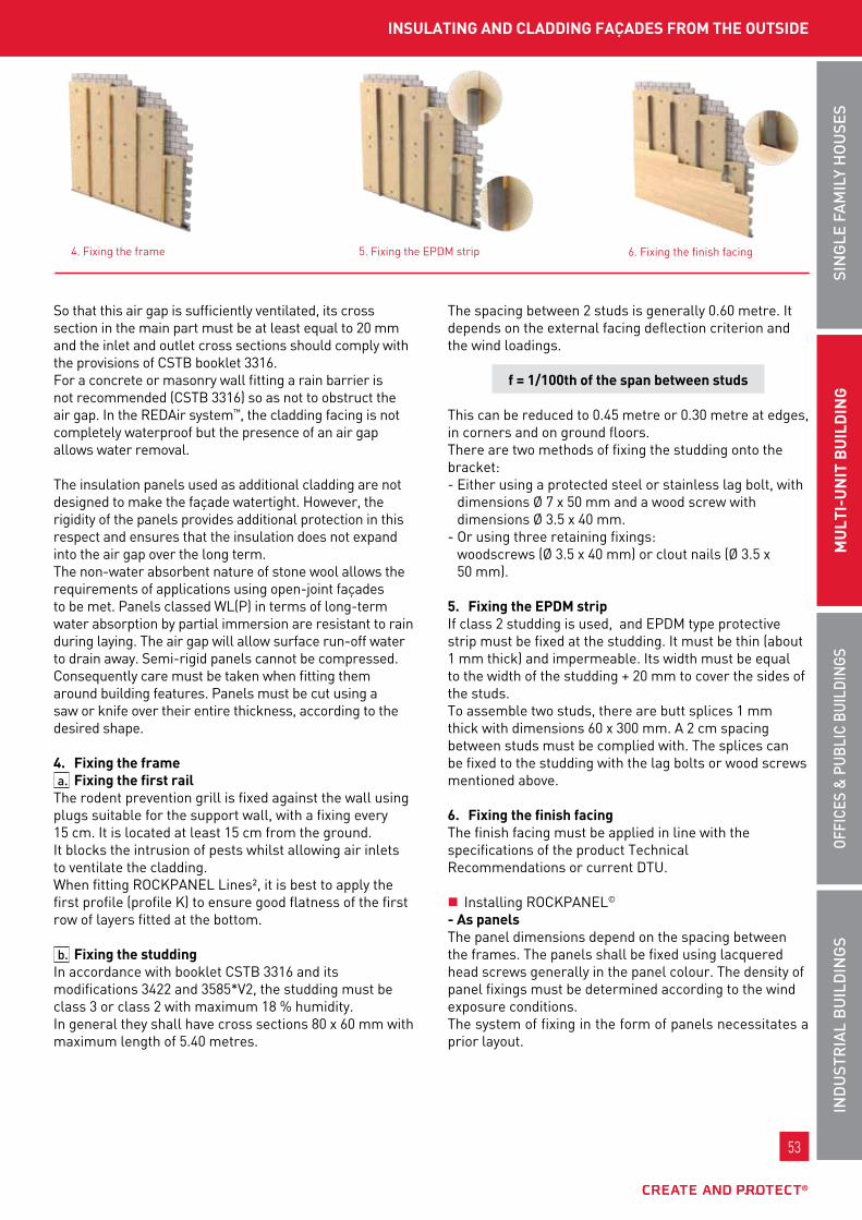
53
InD
uSt
RIA
L B
uIL
DIn
gS
oFFI
CES
& P
uBL
IC B
uIL
DIn
gSSI
ng
LE F
AM
ILy
Ho
uSE
SM
uLt
I-u
nIt
Bu
ILD
Ing
53
InD
uSt
RIA
L B
uIL
DIn
gS
oFFI
CES
& P
uBL
IC B
uIL
DIn
gSM
uLt
I-u
nIt
bu
ILd
Ing
SIn
gLE
FA
MIL
y H
ou
SES
so that this air gap is sufficiently ventilated, its cross section in the main part must be at least equal to 20 mm and the inlet and outlet cross sections should comply with the provisions of cstb booklet 3316.for a concrete or masonry wall fitting a rain barrier is not recommended (cstb 3316) so as not to obstruct the air gap. In the REDAir system™, the cladding facing is not completely waterproof but the presence of an air gap allows water removal. the insulation panels used as additional cladding are not designed to make the façade watertight. However, the rigidity of the panels provides additional protection in this respect and ensures that the insulation does not expand into the air gap over the long term. the non-water absorbent nature of stone wool allows the requirements of applications using open-joint façades to be met. panels classed wl(p) in terms of long-term water absorption by partial immersion are resistant to rain during laying. the air gap will allow surface run-off water to drain away. semi-rigid panels cannot be compressed. consequently care must be taken when fitting them around building features. panels must be cut using a saw or knife over their entire thickness, according to the desired shape.
4. fixing the framea. fixing the first rail
the rodent prevention grill is fixed against the wall using plugs suitable for the support wall, with a fixing every 15 cm. It is located at least 15 cm from the ground.It blocks the intrusion of pests whilst allowing air inlets to ventilate the cladding.when fitting RockpAnEl lines², it is best to apply the first profile (profile k) to ensure good flatness of the first row of layers fitted at the bottom.
b. fixing the studdingIn accordance with booklet cstb 3316 and its modifications 3422 and 3585*v2, the studding must be class 3 or class 2 with maximum 18 % humidity.In general they shall have cross sections 80 x 60 mm with maximum length of 5.40 metres.
the spacing between 2 studs is generally 0.60 metre. It depends on the external facing deflection criterion and the wind loadings.
f = 1/100th of the span between studs
this can be reduced to 0.45 metre or 0.30 metre at edges, in corners and on ground floors.there are two methods of fixing the studding onto the bracket:- Either using a protected steel or stainless lag bolt, with
dimensions Ø 7 x 50 mm and a wood screw with dimensions Ø 3.5 x 40 mm.
- or using three retaining fixings: woodscrews (Ø 3.5 x 40 mm) or clout nails (Ø 3.5 x 50 mm).
5. fixing the EpdM stripIf class 2 studding is used, and EpDm type protective strip must be fixed at the studding. It must be thin (about 1 mm thick) and impermeable. Its width must be equal to the width of the studding + 20 mm to cover the sides of the studs.to assemble two studs, there are butt splices 1 mm thick with dimensions 60 x 300 mm. A 2 cm spacing between studs must be complied with. the splices can be fixed to the studding with the lag bolts or wood screws mentioned above.
6. fixing the finish facingthe finish facing must be applied in line with the specifications of the product technical Recommendations or current Dtu.
� Installing RockpAnEl©
- As panelsthe panel dimensions depend on the spacing between the frames. the panels shall be fixed using lacquered head screws generally in the panel colour. the density of panel fixings must be determined according to the wind exposure conditions.the system of fixing in the form of panels necessitates a prior layout.
4. fixing the frame 5. fixing the EpDm strip
InSuLAtIng And CLAddIng fAçAdES froM tHE outSIdE
6. fixing the finish facing

54
www.rockwool.fr
54
www.rockwool.fr
rEdAir SyStEM
nevertheless, it is necessary to comply with the following distances:
the distance from the edge, for 8 mm thick panels, is:- equal to a1 = 15 mm horizontally- equal to a2 = 50 mm horizontallythe panels are arranged so as to create vertical and horizontal joints of width proportional to the expansion. In practice, this width is defined at a nominal value of 8 mm.Refer to the current RockpAnEl technical Recommendations for panel implementation.
- In Lines² fixing is done using twisted shank nails or flat head screws 15 mm from the edge. we recommend using a nylon head hammer when using nails:- when nailing it is necessary to use two nails at each intersection between the frame and the layer.- when fixing by screwing one screw per intersection between the frame and the layer will be sufficient. when two layers join on a stud, the stud width must allow two fixings to be accommodated.
� Installing sIlvERwooD clapboardfixing sIlvERwooD clapboard is done by stainless steel nails at each intersection between the frames and the clapboard. A minimum depth of 22 mm in the studding is indispensable.
for clapboard with an effective width greater than or equal to 125 mm, clapboard fixing must be used (colour range). the fixing shall be hidden.for clapboard with an effective width greater than 125 mm, two fixings must be used per board, with full layer fixings at top and bottom.the use of this facing is covered by Dtu 41.2"External timber coverings".
� paint/stainwhen installing these stains allow painting and protection for cuts (opening and corner frames). Repainting cuts is mandatory (even if they are not visible) for validity of the 10 year guarantee on the finish of sIlvERwooD products.these stains also allow retouching, repair of small areas damaged during installation, or can play a decorative role.there are different maintenance products to protect, clean and conserve the initial colour of the different claddings.
7. End of workbare insulation offcuts and packaging must be returned to a distributor providing collection of non-hazardous inert wastes (for the insulation) and non hazardous non-inert wastes (for the packaging), to a waste recycling centre or building waste sorting centres.
Hidden fixings visible fixings
7. End of work

55
InD
uSt
RIA
L B
uIL
DIn
gS
oFFI
CES
& P
uBL
IC B
uIL
DIn
gSSI
ng
LE F
AM
ILy
Ho
uSE
SM
uLt
I-u
nIt
Bu
ILD
Ing
55
InD
uSt
RIA
L B
uIL
DIn
gS
oFFI
CES
& P
uBL
IC B
uIL
DIn
gSM
uLt
I-u
nIt
bu
ILd
Ing
SIn
gLE
FA
MIL
y H
ou
SES
InSuLAtIng And CLAddIng fAçAdES froM tHE outSIdE
reference documents Implementation standards
- cstb booklet 3316 and its modifications 3422 and 3585 v2
- RockpAnEl Durable/Durable Ag timber frame technical Recommendation. product standard: nf En 13162 products manufactured in mineral wool (mw)
orders and decreesbuilding energy performance:
order of 24 may 2006 on the thermal characteristics of new buildings and new parts of buildings. Decree no. 2006-592 of 24 may 2006 on building thermal characteristics and energy performance. order of 15 september 2006 on energy performance diagnosis for existing buildings offered for sale in metropolitan france. order of 3 may 2007 on energy performance diagnosis for existing buildings used mainly as dwellings and offered for rent in metropolitan france. order of 3 may 2007 on thermal characteristics and energy performance of existing buildings. order of 13 June 2008 on the energy performance of existing buildings with area greater than 1,000 square metres, when they are subject to major renovation works. order of 21 september 2007 on energy performance diagnosis for new buildings in metropolitan france.
fire regulations: order of 25 June 1980 approving the general provisions of the safety regulations against the risk of fire and panic in buildings open to the public (ERp - Etablissements Recevant du public).
order of 24 may 2010 approving various provisions completing and modifying the safety regulations against the risk of fire and panic in buildings open to the public (included in the revision of articles co20 and co21 and technical instruction no. 249 - version 2010). order of 31 January 1986 on protection of dwellings against fire. technical Instruction no. 249 of 21 June 1982 on façades.
Acoustic regulations:
order of 30 June 1999 - nRA 2000 housing regulations order of 25 April 2003 - Health care establishment regulations order of 25 April 2003 - Educational establishment regulations order of 25 April 2003 - Hotel regulations order of 30 may 1996 - Regulations for external acoustic insulation Decree of 31 August 2006 - Environmental noise regulations
InSurAnCEten-year civil Responsibility insurance policy for building material manufacturers, importers and equivalents, covering Rockwool france s.A.s in application of the provisions of the law of January 4, 1978 and Article 1792-4 of the french civil code, to the exclusion of all installers’ guarantees.no reference to the name and brand of this product can be made in technical recommendations or technical documents without the written agreement of Rockwool france.
* Current Technical Recommendations available on the site www.cstb.com. Refer to our Internet site to find out the latest update of the datasheet.

56
www.rockwool.fr
56
www.rockwool.fr
roCkfAçAdE
single-density bare stone wool slabs, used for insulating façades between all types of added cladding frameworks.
REFEREnCES, PACkIng
tECHnICAL CHARACtERIStICS
ADVAntAgES
roCkfAçAdE
Reaction to fire RockfAçADE is incombustible; consequently it does not contribute to the development of the fire (Euroclass A1).the use of an incombustible rockwool insulation allows compliance with the requirements of technical instruction It no. 249.
FIRE SAFEty
CERtIFICAtES
ACERMI kEyMARk CE 02/015/027 008-sDg5-027 1163-cpD-0013
DoP cpR- Dop-fR-019
weight characteristics performance
thermal conductivity (w/m.k) 0.035
Reaction to fire (Euroclass) A1
nominal density (kg/m3) 39
semi-rigidity criteria AcERmI certified
thickness tolerance t3Dimensional stability under specified temperature and humidity conditions Ds(70,90)
short term water absorption ws
long term water absorption wl(p)
water vapour transmission mu1
ReferenceDimensions
l x w x t (mm)thermal resistance
(m².k/w)number
of units / packagesnumber of
m²/ packagenumber of
packages / palletnumber ofm²/ pallet
63605 1350 x 600 x 55 1.55 8 6.48 12 77.76
63606 1350 x 600 x 70 2.00 6 4.86 12 58.32
63433 1350 x 600 x 80 2.25 6 4.86 12 58.32
63432 1350 x 600 x 100 2.85 5 4.05 12 48.60
63403 1350 x 600 x 120 3.40 4 3.24 12 38.88
63254 1350 x 600 x 140 4.00 3 2.43 12 29.16
63795 1350 x 600 x 150 4.25 3 2.43 12 29.16
63062 1350 x 600 x 160 4.55 3 2.43 12 29.16
Excellent mechanical behaviour of the product in use, reduced number of fixings.
Density scale— +

57
InD
uSt
RIA
L B
uIL
DIn
gS
oFFI
CES
& P
uBL
IC B
uIL
DIn
gSSI
ng
LE F
AM
ILy
Ho
uSE
SM
uLt
I-u
nIt
Bu
ILD
Ing
57
InD
uSt
RIA
L B
uIL
DIn
gS
oFFI
CES
& P
uBL
IC B
uIL
DIn
gSM
uLt
I-u
nIt
bu
ILd
Ing
SIn
gLE
FA
MIL
y H
ou
SES
ExtErnAL tHErMAL InSuLAtIon/MASonry wALLS undEr AddEd fACAdE
single density panel covered with a black glass sheet.
REFEREnCES, PACkIng
tECHnICAL CHARACtERIStICS
ADVAntAgES
roCkgLACE
CERtIFICAtES
ACERMI kEyMARk CE 02/015/029 008-sDg5-029 1163-cpD-0013
DoP cpR- Dop-fR-019
weight characteristics performance
Reaction to fire (Euroclass) A1
thermal conductivity (w/m.k) 0.035
fire loading (mJ/m2/cm) 0*
nominal density (kg/m3) 39
semi-rigidity criteria AcERmI certified
length (mm) 1350
width (mm) 600
thickness tolerance t3Dimensional stability under specified temperature and humidity conditions Ds(70,90)
long term water absorption wl(p)
short term water absorptionwith partial immersion ws
water vapour transmission mu1
black glass fibre film covering for all applications behind a perforated or openwork facing. Allowed in ERp (buildings open to the public) - Euroclass A1 - incombustible.
ReferenceDimensions
l x w x t (mm)
Resistanceresistance
(m².k/w)
number of panels/
package
numberof m²/pallet
number of parts/
pallet
numberof pack./
pallet
tautliner lorry m²/ load
(22 pallets)minimum
quantity EAn codes
72526 1350 x 600 x 55 1.55 10 64.80 80 8 1,425.60 - 3 53731 0072801
72527 1350 x 600 x 70 2.00 9 58.32 72 8 1,283.04 - 3 53731 0072818
72529 1350 x 600 x 80 2.25 7 45.36 56 8 997.92 - 3 53731 0072825
72532 1350 x 600 x 100 2.85 6 38.88 48 8 855.36 - 3 53731 0072832
72533 1350 x 600 x 120 3.40 5 32.40 40 8 712.80 - 3 53731 0072849
72534 1350 x 600 x 140 4.00 4 25.92 32 8 570.24 - 3 53731 0072856
72535 1350 x 600 x 150 4.25 4 25.92 32 8 570.24 - 3 53731 0072863
Density scale— +
* Due to its Euroclass A1 rating, the ROCKGLACE product should not be associated with the term “Combustible Material” as defined by the fire safety regulations applicable to the façade. For this reason ROCKGLACE is exempt from calculation in the general evaluation of the available combustible mass in the façade. Its available combustible mass is considered as zero.

58
www.rockwool.fr
58
www.rockwool.fr
roCkfAçAdE
Step 1: preparing the work siteA prior study must define the methods of fixing the ex-ternal thermal insulation system and the added cladding frame spacing, which can vary depending on the climate constraints (snow and wind rules), the mechanical con-straints (shock resistance), implementation constraints (cladding dimensions, fixing density, seismic resistance...) and the specific features of the structure (height, geom-etry, corners, openings...).the rigid or semi-rigid insulation panels must be supplied to the site and stored with protection from bad weather.Rockwool panels for which the AcERmI certificate in-dicates the ws and "semi-rigid insulation" classifications comply with the recommendations of CStb booklets nos. 3585*V2 and 3586*V2.the insulation fixing plugs must be supplied separately in sufficient numbers (minimum 2 plugs per panel).
Step 2: Installing frame supportsthe installation of frame supports (brackets or clips) must be done in accordance with the manufacturer's specifica-tions and the rules of the art (dtu and CStb booklets).the choice of insulation has no effect on the method of installing the frame.the insulation is merely a filling component intended to ensure the thermal and acoustic insulation of the façade. the use of an insulation made from stone wool, which is incombustible by nature (Euroclass A1), helps improve the performance of the façade in terms of fire risk.
Step 3: Insulation fixingthere are two possible methods for installing panels for additional cladding and attached stone coverings, with and without prior cutting.the fixings for cladding and equipment added to the facade (brackets, spacers, supports for scaffolding, luminaires, signs, gutters,…) are considered to be already installed in accordance with their respective manufactur-ers' instructions.
Without prior cutting:the rigid and semi-rigid panels must be grooved over their entire thickness in order to be pinned more easily to the metal brackets already fixed to the support wall.Rockwool stone wool panels cannot be pinned without this prior groove being made, at the risk of damaging the insulation.for this installation method, the timber or metal frame-work uprights must not be installed before the insulation.
With prior cutting:the panels must be cut to the spaces between the frames. this space can be:- Either the distance between 2 lines of metal brackets if
the panels are fitted behind the framework.- or the distance between 2 frame edges (metal uprights
or studding) if the panels are fitted between the frame-work.
for an already installed t shaped metal frame and so as not to damage the panels, it is advisable to cut each panel as indicated in the figure opposite.
APPLICAtIon
can be used with AlpHARock*
*See the technical characteristics of ALPhAROCK p.28
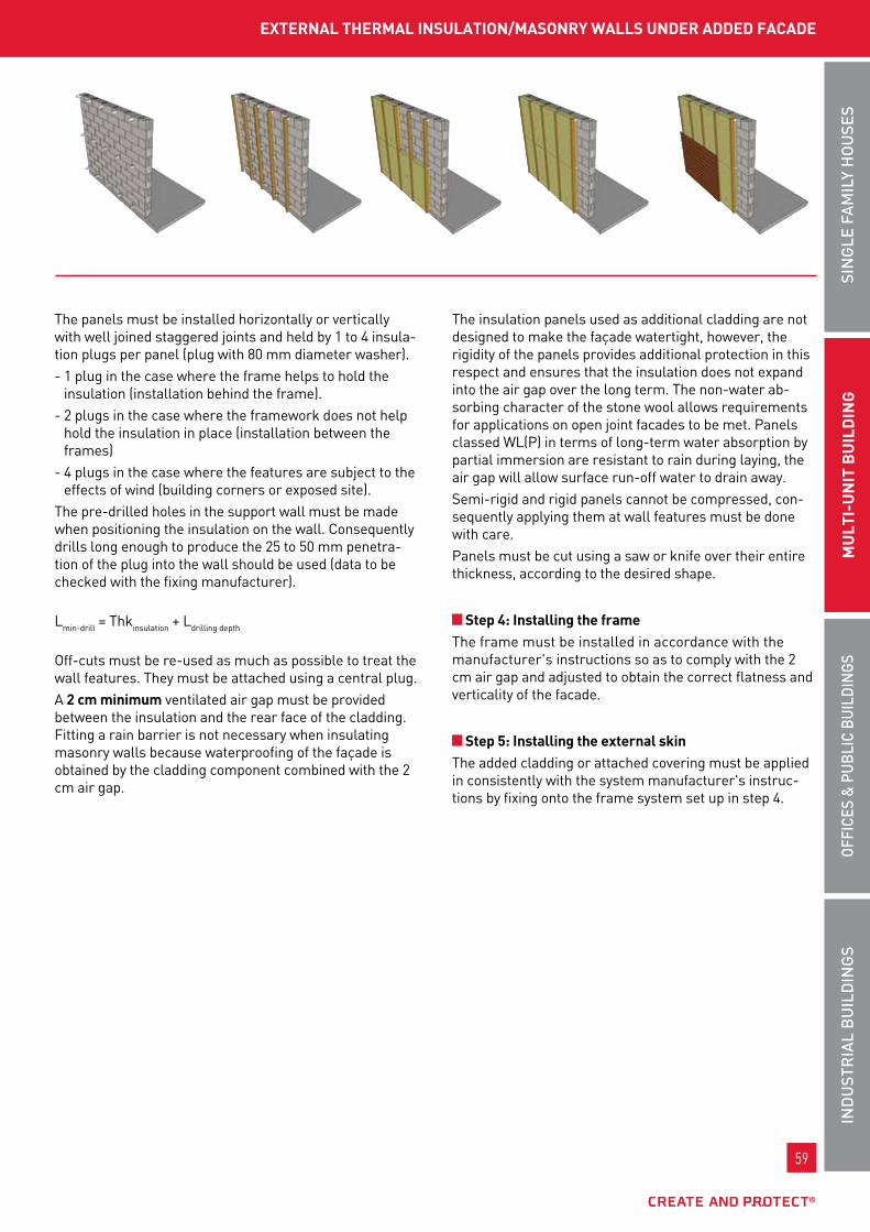
59
InD
uSt
RIA
L B
uIL
DIn
gS
oFFI
CES
& P
uBL
IC B
uIL
DIn
gSSI
ng
LE F
AM
ILy
Ho
uSE
SM
uLt
I-u
nIt
Bu
ILD
Ing
59
InD
uSt
RIA
L B
uIL
DIn
gS
oFFI
CES
& P
uBL
IC B
uIL
DIn
gSM
uLt
I-u
nIt
bu
ILd
Ing
SIn
gLE
FA
MIL
y H
ou
SES
ExtErnAL tHErMAL InSuLAtIon/MASonry wALLS undEr AddEd fACAdE
the panels must be installed horizontally or vertically with well joined staggered joints and held by 1 to 4 insula-tion plugs per panel (plug with 80 mm diameter washer).- 1 plug in the case where the frame helps to hold the
insulation (installation behind the frame).- 2 plugs in the case where the framework does not help
hold the insulation in place (installation between the frames)
- 4 plugs in the case where the features are subject to the effects of wind (building corners or exposed site).
the pre-drilled holes in the support wall must be made when positioning the insulation on the wall. consequently drills long enough to produce the 25 to 50 mm penetra-tion of the plug into the wall should be used (data to be checked with the fixing manufacturer). lmin-drill = thkinsulation + ldrilling depth
off-cuts must be re-used as much as possible to treat the wall features. they must be attached using a central plug.A 2 cm minimum ventilated air gap must be provided between the insulation and the rear face of the cladding. fitting a rain barrier is not necessary when insulating masonry walls because waterproofing of the façade is obtained by the cladding component combined with the 2 cm air gap.
the insulation panels used as additional cladding are not designed to make the façade watertight, however, the rigidity of the panels provides additional protection in this respect and ensures that the insulation does not expand into the air gap over the long term. the non-water ab-sorbing character of the stone wool allows requirements for applications on open joint facades to be met. panels classed wl(p) in terms of long-term water absorption by partial immersion are resistant to rain during laying, the air gap will allow surface run-off water to drain away.semi-rigid and rigid panels cannot be compressed, con-sequently applying them at wall features must be done with care.panels must be cut using a saw or knife over their entire thickness, according to the desired shape.
Step 4: Installing the framethe frame must be installed in accordance with the manufacturer's instructions so as to comply with the 2 cm air gap and adjusted to obtain the correct flatness and verticality of the facade.
Step 5: Installing the external skinthe added cladding or attached covering must be applied in consistently with the system manufacturer's instruc-tions by fixing onto the frame system set up in step 4.
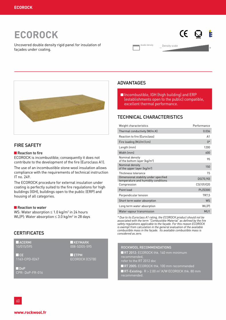
60
www.rockwool.fr
60
www.rockwool.fr
ECoroCk
ADVAntAgES
ECoroCk
Incombustible, IgH (high building) and ERp (establishments open to the public) compatible, excellent thermal performance.
uncovered double density rigid panel for insulation of façades under coating.
CERtIFICAtES
ACERMI kEyMARk 10/015/595 008-sDg5-595
CE EtPM 1163-cpD-0247 EcoRock (cstb)
DoP cpR- Dop-fR-016
tECHnICAL CHARACtERIStICS
weight characteristics performance
thermal conductivity (w/m.k) 0.036
Reaction to fire (Euroclass) A1
fire loading (mJ/m2/cm) 0*
length (mm) 1200
width (mm) 600
nominal densityof the bottom layer (kg/m3) 95
nominal densityof the upper layer (kg/m3) 150
thickness tolerance t5Dimensional stability under specified temperature and humidity conditions Ds(70,90)
compression cs(10\y)20
point load pl(5)300
perpendicular tension tR7,5
short term water absorption ws
long term water absorption wl(p)
water vapour transmission mu1
* Due to its Euroclass A1 rating, the ECOROCK product should not be associated with the term “Combustible Material” as defined by the fire safety regulations applicable to the façade. For this reason ECOROCK is exempt from calculation in the general evaluation of the available combustible mass in the façade. Its available combustible mass is considered as zero.
Reaction to fire EcoRock is incombustible; consequently it does not contribute to the development of the fire (Euroclass A1). the use of an incombustible stone wool insulation allows compliance with the requirements of technical instruction It no. 249. the EcoRock procedure for external insulation under coating is perfectly suited to the fire regulations for high buildings (IgH), buildings open to the public (ERp) and housing of all categories.
Reaction to water ws: water absorption ≤ 1.0 kg/m2 in 24 hours wl(p): water absorption ≤ 3.0 kg/m2 in 28 days
FIRE SAFEty
RoCkWooL RECoMMEnDAtIonS
Rt 2012: EcoRock thk. 140 mm minimum recommended, refer to the Rt 2012 doc
Rt 2005: EcoRock thk. 100 mm recommended
Rt-Existing: R > 2.00 m2.k/w EcoRock thk. 80 mm recommended.
Density scale— +
double density

61
InD
uSt
RIA
L B
uIL
DIn
gS
oFFI
CES
& P
uBL
IC B
uIL
DIn
gSSI
ng
LE F
AM
ILy
Ho
uSE
SM
uLt
I-u
nIt
Bu
ILD
Ing
61
InD
uSt
RIA
L B
uIL
DIn
gS
oFFI
CES
& P
uBL
IC B
uIL
DIn
gSM
uLt
I-u
nIt
bu
ILd
Ing
SIn
gLE
FA
MIL
y H
ou
SES
InSuLAtIng ExtErnAL tHErMAL rEndErEd fAçAdE
REFEREnCES, PACkIng
ReferenceDimensions
l x w x t (mm)
thermal resistance
(m².k/w)
number of units /
packages
number of m2/
package
numberof parts/
pallet
numberof m²/pallet
tautliner lorry m²/ load
(22 pallets) EAn codes
77222* 1200 x 600 x 50 1.35 1 0.72 96 69.12 1,520.64 3 53731 0076830
86850 1200 x 600 x 60 1.65 1 0.72 80 57.60 1267.20 3 53731 0081339
77223* 1200 x 600 x 80 2.20 1 0.72 60 43.20 950.40 3 53731 0076847
77224 1200 x 600 x 100 2.75 1 0.72 48 34.56 760.32 3 53731 0076854
77225 1200 x 600 x 120 3.30 1 0.72 40 28.80 633.60 3 53731 0076861
77221 1200 x 600 x 140 3.85 1 0.72 36 25.92 570.24 3 53731 0076823
77210 1200 x 600 x 160 4.40 1 0.72 32 23.04 506.88 3 53731 0076816
Specific delivery time: * 5 to 10 days
pALLEtS SoLd In MuLtIpLES of 2

62
www.rockwool.fr
62
www.rockwool.fr
ECoroCk
tHERMAL PERFoRMAnCE
Hollow block walls 200 mm
up (w/m2.k)
thk.(mm)
R(m2.k/w)
uc(w/m2.k)
5 fixings / panel
7 fixings / panel
9 fixings / panel
50 1.35 0.56 0.58 0.58 0.59
80 2.20 0.38 0.40 0.40 0.41
100 2.75 0.32 0.33 0.33 0.34
120 3.30 0.27 0.28 0.29 0.29
140 3.85 0.23 0.25 0.25 0.26
160 4.40 0.21 0.22 0.23 0.23
Hollow block walls, 200 mm
up (w/m2.k)
thk. (mm)
R(m2.k/w)
uc(w/m2.k)
5 fixings / panel
7 fixings / panel
9 fixings / panel
50 1.35 0.45 0.47 0.47 0.48
80 2.20 0.33 0.34 0.35 0.35
100 2.75 0.28 0.29 0.30 0.30
120 3.30 0.24 0.25 0.26 0.27
140 3.85 0.21 0.23 0.23 0.24
160 4.40 0.19 0.20 0.21 0.22
Concrete walls 180 mm
up (w/m2.k)
thk. (mm)
R(m2.k/w)
uc(w/m2.k)
5 fixings / panel
7 fixings / panel
9 fixings / panel
50 1.35 0.61 0.63 0.63 0.64
80 2.20 0.40 0.42 0.42 0.43
100 2.75 0.33 0.34 0.35 0.36
120 3.30 0.28 0.29 0.30 0.30
140 3.85 0.24 0.26 0.26 0.27
160 4.40 0.21 0.23 0.23 0.24
Calculation assumptions: - thin coating - plastic plug stainless steel screw plastic head - hollow block wall: R=0,23 m2.k/w - concrete wall: R=0.09 m2.k/w - brick wall: R=0.67 m2.k/w
Attenuation:An external insulation system under coating including EcoRock or 431 IEsE panels improves the acoustic performance of the initial wall. this improvement can reach DRA = +12 db.
ACouStIC PERFoRMAnCE
Rw (c;ctr) in db
RA RA,tr
meets the essentials of the acoustic regulations
concrete thk.160 mm59 (-2; -6)
57 53
concrete thk.160 mm+ EcoRock thk.100 mm(7 fixings / panel)+ thin ARmAtERm coating. 5 mm
62 (-3; -9)
59 53
Ac10-26027913-3
meets the essentials of the acoustic regulations (except for the requirement for class 1 roads)
Hollow block thk. 200 mmcoating 1 face 15 mm
51 (-1; -4)
50 47
Hollow block thk. 200 mmcoating 1 face 15 mm+ EcoRock thk.100 mm(7 fixings / panel)+ thin pARIso coating lR 15 mm
57 (-4; -9)
53 48
Ac10-26027410-1
lAbElRock thk. 10+60 mmHollow block thk. 200 mmcoating 1 face 15 mm+ EcoRock thk.100 mm(7 fixings / panel)+ thin pARIso coating lR 15 mm
59 (-5; -12)
54 47
Ac10-26027410-3
meets the essentials of the current acoustic regulations
Hollow brickthk. 200 mm coating on 1 face 15 mm
42 (0; -3)
42 39
Hollow brick coating thk. 200 mmEcoRock thick coating 15 mm
56 (-2; -7)
54 49
Ac10-26026726-1b

63
InD
uSt
RIA
L B
uIL
DIn
gS
oFFI
CES
& P
uBL
IC B
uIL
DIn
gSSI
ng
LE F
AM
ILy
Ho
uSE
SM
uLt
I-u
nIt
Bu
ILD
Ing
63
InD
uSt
RIA
L B
uIL
DIn
gS
oFFI
CES
& P
uBL
IC B
uIL
DIn
gSM
uLt
I-u
nIt
bu
ILd
Ing
SIn
gLE
FA
MIL
y H
ou
SES
InSuLAtIng ExtErnAL tHErMAL rEndErEd fAçAdE
Step 1: preparing the work siteA prior study must define the methods of fixing the external thermal insulation system and, which can vary depending on the mechanical constraints (shock resistance), implementation constraints (fixing density, etc.) and the specific features of the structure (height, geometry, corners, openings, etc.).the insulation fixing plugs must be supplied separately in sufficient number (density defined according to the specifications of the technical recommendation or the DtA from the supplier of the external insulation system under coating). the other accessories used in this technique must also be provided according to the same specifications (profiles, meshes, fabric corner reinforcements, bags of coating, corner rods, etc.).the minimum number of plugs is determined from the normal wind forces according to exposure and the allowable load for the plugs in the support considered. this will always be ≥ 5 plugs per panel.It is necessary to increase the number of plugs in the special features and peripheral zones. the plug's unbuttoning resistance must comply with paragraph 5.1.4.3.1 of European technical Agrement guide no. 004 (EtAg 004).A vt90 (EJot company) additional rose can be added to the head of the plug.only flush mounting is allowed for ECoroCk.
the pallets must be supplied to the site and can be stored outside for several weeks provided that the packaging is in good condition and they are protected from shocks and bad weather. the packages should be opened as close as possible to the installation location.
Step 2: Insulation fixing
IMportAntEcoRock panels must be placed with the higher density face towards the outside to resist puncturing by the plug. the higher density face is indicate by surface burning marking. Any panel installed the other way round must be turned round before applying the coating.
the panels must be wedged and plugged onto the support wall in accordance with the specifications of the technical recommendation of system manufacturer's DtA.the panel is then pressed against the support wall by pressing onto the starting rail for the first row then onto the other panels that have already been installed for the upper rows.the panels must be fitted with well jointed offset joints.maximum reuse of the offcuts must be made to treat special points.the pre-drilled holes must be drilled before bonding the insulation to ensure sufficient depth of the plug in accordance with the specifications of the manufacturer of the plug or external insulation kit under coating (IEsE).consequently drills long enough to produce the penetration of the plug into the wall should be used (data to be checked with the fixing manufacturer).lmin-drill = thkinsulation + ldrilling depth
APPLICAtIon
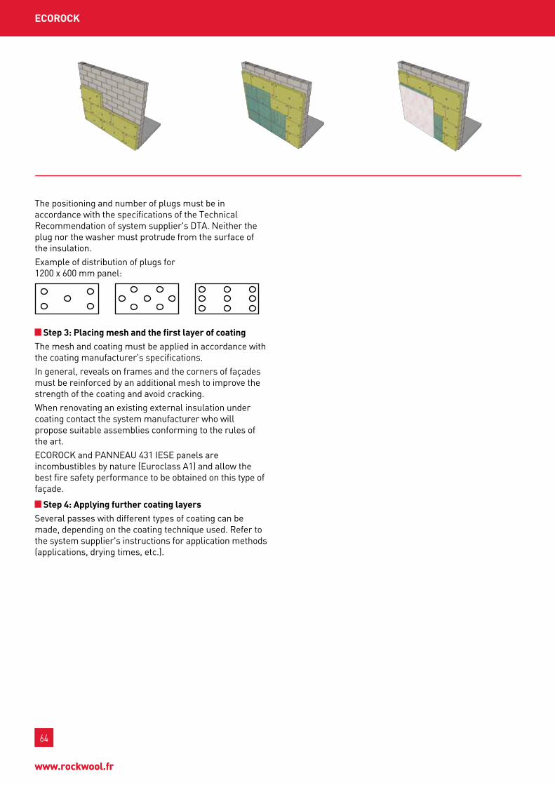
64
www.rockwool.fr
64
www.rockwool.fr
ECoroCk
the positioning and number of plugs must be in accordance with the specifications of the technical Recommendation of system supplier's DtA. neither the plug nor the washer must protrude from the surface of the insulation.Example of distribution of plugs for 1200 x 600 mm panel:
Step 3: placing mesh and the first layer of coatingthe mesh and coating must be applied in accordance with the coating manufacturer's specifications.In general, reveals on frames and the corners of façades must be reinforced by an additional mesh to improve the strength of the coating and avoid cracking.when renovating an existing external insulation under coating contact the system manufacturer who will propose suitable assemblies conforming to the rules of the art.EcoRock and pAnnEAu 431 IEsE panels are incombustibles by nature (Euroclass A1) and allow the best fire safety performance to be obtained on this type of façade.
Step 4: Applying further coating layersseveral passes with different types of coating can be made, depending on the coating technique used. Refer to the system supplier's instructions for application methods (applications, drying times, etc.).

65
InD
uSt
RIA
L B
uIL
DIn
gS
oFFI
CES
& P
uBL
IC B
uIL
DIn
gSSI
ng
LE F
AM
ILy
Ho
uSE
SM
uLt
I-u
nIt
Bu
ILD
Ing
65
InD
uSt
RIA
L B
uIL
DIn
gS
oFFI
CES
& P
uBL
IC B
uIL
DIn
gSM
uLt
I-u
nIt
bu
ILd
Ing
SIn
gLE
FA
MIL
y H
ou
SES

66
www.rockwool.fr
66
www.rockwool.fr
roCkfEu CoffrAgE
single-density bare stone wool panel, used for insulating slabs poured in situ on the insulation.
ADVAntAgES
roCkfEu CoffrAgE
Reaction to fire RockfEu coffRAgE is incombustible; consequently it does not contribute to the development of the fire (Euroclass A1).
Attenuationtest performed on 160 mm concrete slab
Absorptiontest performed o n RockfEu coffRAgE thk. 80 mmaw = 0.90
FIRE SAFEty
CERtIFICAtES
ACERMI kEyMARk CE 07/015/455 008-sDg5-455 1163-cpD-0175
DoP cpR- Dop-fR-010
thickness (mm) 100 110 120 130 140
up* (w/m2.k) 0.33 0.30 0.28 0.26 0.24
small format suited to small area sites or sites with numerous special points.
ACouStIC PERFoRMAnCE
test of standard 12.5 mm plaster board inner partition on 200 mm hollow block wall + 15 mm coating.
systemsRw (c;ctr) in db
RA RA,tr
uninsulated concrete slab, 160 mm58 (-1; -5)
57 53
slab insulated with Rocksol coffRAgE thk. 100 mm (polyane layer inserted between the insulation and the concrete slab)
48 (-8; -17)
61 55
CTBA Tests: no. 713-950-0094/1
*Calculations performed for 23 cm concrete slab.
CSTB Test: no. 24545
tHERMAL PERFoRMAnCE*
tECHnICAL CHARACtERIStICS
weight characteristics performance
thermal conductivity (w/m.k) 0.038
Reaction to fire (Euroclass) A1
nominal density (kg/m3) 120
thickness tolerance t5Dimensional stability at specified temperature Ds(tH)
short term water absorption ws
compression cs(10)30
point load pl(5)200
long term water absorption wl(p)
water vapour transmission mu1
Density scale— +
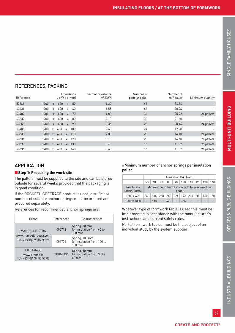
67
InD
uSt
RIA
L B
uIL
DIn
gS
oFFI
CES
& P
uBL
IC B
uIL
DIn
gSSI
ng
LE F
AM
ILy
Ho
uSE
SM
uLt
I-u
nIt
Bu
ILD
Ing
67
InD
uSt
RIA
L B
uIL
DIn
gS
oFFI
CES
& P
uBL
IC B
uIL
DIn
gSM
uLt
I-u
nIt
bu
ILd
Ing
SIn
gLE
FA
MIL
y H
ou
SES
InSuLAtIng fLoorS / At tHE bottoM of forMwork
APPLICAtIon Step 1: preparing the work site
the pallets must be supplied to the site and can be stored outside for several weeks provided that the packaging is in good condition.If the RockfEu coffRAgE product is used, a sufficient number of suitable anchor springs must be ordered and procured separately.References for recommended anchor springs are:
Minimum number of anchor springs per insulation pallet:
whatever type of formwork table is used this must be implemented in accordance with the manufacturer's instructions and current safety rules.partial formwork tables must be the subject of an individual study by the system supplier.
brand References characteristics
mAnDEllI sEtRAwww.mandelli-setra.comtel: +33 (0)3.25.82.30.21
005712spring, 80 mm for insulation from 60 to 100 mm
005705spring, 100 mm for insulation from 100 to 180 mm
lR EtAncowww.etanco.fr
tel: +33 (0)1.34.80.52.00spIR-Eco
spring, 80 mm for insulation from 30 to 60 mm
Insulation thk. (mm)
50 60 70 80 90 100 110 120 130 140
Insulation format (mm)
minimum number of springs to be procured per pallet
1200 x 600 240 336 288 240 224 192 200 200 160 160
1200 x 1000 - 588 - 420 - 336 - - - -
REFEREnCES, PACkIng
ReferenceDimensions
l x w x t (mm)thermal resistance
(m².k/w)number of
panels/ palletnumber ofm²/ pallet minimum quantity
53768 1200 x 600 x 50 1.30 48 34.56 -
63631 1200 x 600 x 60 1.55 42 30.24 -
63402 1200 x 600 x 70 1.80 36 25.92 24 pallets
63632 1200 x 600 x 80 2.10 30 21.60 -
63258 1200 x 600 x 90 2.35 28 20.16 24 pallets
53485 1200 x 600 x 100 2.60 24 17.28 -
63633 1200 x 600 x 110 2.85 20 14.40 24 pallets
63634 1200 x 600 x 120 3.15 20 14.40 24 pallets
63635 1200 x 600 x 130 3.40 16 11.52 24 pallets
63636 1200 x 600 x 140 3.65 16 11.52 24 pallets

68
www.rockwool.fr
68
www.rockwool.fr
Step 2: Insulation fixingthe insulation laying support (formwork table) is assumed to be installed and secure. Its mechanical strength must be sufficient to support the weight of the insulation, the slab, people working on the structure, etc.the RockfEu rigid stone wool panels must be laid directly on the formwork table edge to edge, fully joined together and at staggered joints.particular attention should be paid to the features (corners, edges, floor opening blockouts, duct shafts, etc.).for RockfEu coffRAgE, a polyethylene film can be applied on the insulating layer to avoid penetration by concrete laitance.RockfEu coffRAgE panels are made from rigid single or double density stone wool and allow people to walk on the insulation. their compression classification is AcERmI certified.their dimensional stability is also certified and resists significant variations in temperature (70°c) and humidity (90%).their behaviour in water allows them to resist being penetrated by dripping water and, in the event of prolonged immersion, the panels' properties return to normal once dry.
Step 3: fitting anchor springsfor RockfEu coffRAgE only, suitable anchor springs must be placed on the insulation panels, with 5, 8, 10 or 14 springs per panel depending on the thickness.the springs must protrude from the insulation in order to ensure they are surrounded by concrete over 30 mm.
Minimum number of anchor springs per insulation panel
Insulation thickness (mm)
50 60 70 80 90 100 110 120 130 140
Insulation format (mm) no. of springs per panel
1200 x 600 5 8 10
1200 x 1000 - 14 - - - -
panel offcuts must be fastened with the same fastening density per unit area.the anchor springs must be distributed evenly over each panel.
Example of distribution:
Step 4: Laying frames and spacersthe frames defined by the contract documents and suited to the slab to be poured must be laid on the insulating layer on top of point spacers.these spacers will ensure that the steel parts are completely covered.
Step 5: pouring the slabthe slab should be poured according to the recommendations of its supplier and the site organisation, in accordance with good practice.
Step 6: dismantling the props and formwork tablethe slab drying time and form work removal operations follow the recommendations of the contract documents particular to each site.Insulation laying does not affect concrete setting times.
Step 7: Applying finishesonce the concrete pouring steps are complete and the supporting props dismantled, the RockfEu panels can be painted to improve the aesthetic rendering on the underside. painting should be carried out using vinyl resin-based paint in water phase (sopAfom bm99 brand if fire constraints must be retained).Application can be by roller or compressed-air spray gun.
roCkfEu CoffrAgE
SopAfoM tel: +33 (0)3.26.80.02.32 fax: +33 (0)3.26.80.06.72

69
InD
uSt
RIA
L B
uIL
DIn
gS
oFFI
CES
& P
uBL
IC B
uIL
DIn
gSSI
ng
LE F
AM
ILy
Ho
uSE
SM
uLt
I-u
nIt
Bu
ILD
Ing
69
InD
uSt
RIA
L B
uIL
DIn
gS
oFFI
CES
& P
uBL
IC B
uIL
DIn
gSM
uLt
I-u
nIt
bu
ILd
Ing
SIn
gLE
FA
MIL
y H
ou
SES

70
www.rockwool.fr
70
www.rockwool.fr
roCkfEu rEI 60 rSd & roCkfEu rEI 120 rSd
RockfEu REI 60 RsD and RockfEu REI 120 RsD are double-density bare stone wool panels, used for insulating existing slabs by plugging to their underside.
ADVAntAgES
roCkfEu rEI 60 rsd & roCkfEu rEI 120 rsd
Reaction to fireRockfEu REI 60 RsD and RockfEu REI 120 RsD are incombustible; consequently they do not contribute to the development of the fire (Euroclass A1).
fire resistancesummary table for fire tests performed (reinforced concrete slab, thk. 140 mm):
length according to the thickness of the insulation (consult manufacturers' technical data sheets).the following models of plug have been validated by the fire resistance test mentioned: - IDms (HIltI) - IsomEt (spIt) - mEtAlIso (lR EtAnco)
Absorptionaw = 0.90
FIRE SAFEty
CERtIFICAtES
roCkfEu rEI 60 rsd for sites requiring minimum fire resistance.
roCkfEu rEI 120 rsd guaranteed fire and acoustic performance,
number of fastenings reduced to 5 plugs per panel.
ACouStIC PERFoRMAnCE
Test no. FCBA404-08-47-6/A (Rockfeu REI60 RSD) thk. 80 mmTest no. FCBA404-08-47-6/B (Rockfeu REI120 RSD) thk. 80 mm
References no. ofplugs
fire resistance performance /Report no. / thickness range (mm)
RockfEu REI 60 RsD 5 1 h pv 08-A-120 60
RockfEu REI 120 RsD 2 h pv 07-A-039
pv 06-A-29260
70-80-90-110
tECHnICAL CHARACtERIStICS
weight characteristics performance
thermal conductivity (w/m.k) 0.035 / 0.034
Reaction to fire (Euroclass) A1
nominal density of lower layer (kg/m3) 60 / 65
nominal density of upper layer (kg/m3) 110
thickness tolerance t5Dimensional stability under specified temperature and humidity conditions Ds(tH)
short term water absorption ws
water vapour transmission mu1
A CTBA test: no. 07/CTBA-IBC/PY/130/2b CTBA test: no. 404/07/130/6
Attenuation
systemsRw (c;ctr) in db
RA RA,tr
uninsulated concrete slab, 160 mm55 (-3; -7)
52 48
A slab insulated with RockfEu REI 60 RsD thk. 120 mm
57 (-3; -8)
54 49
b slab insulated with RockfEu REI 120 RsDthk. 150 mm
59 (-3; -8)
56 51
roCkfEu rEI 60 rsd ACERMI kEyMARk CE
07/015/445 008-sDg5-445 1163-cpD-0181
DoP cpR- Dop-fR-006
roCkfEu rEI 120 rsd ACERMI kEyMARk CE
07/015/443 008-sDg5-443 1163-cpD-0169
DoP cpR- Dop-fR-007
Density scale— +
double density
Density scale— +
double density

71
InD
uSt
RIA
L B
uIL
DIn
gS
oFFI
CES
& P
uBL
IC B
uIL
DIn
gSSI
ng
LE F
AM
ILy
Ho
uSE
SM
uLt
I-u
nIt
Bu
ILD
Ing
71
InD
uSt
RIA
L B
uIL
DIn
gS
oFFI
CES
& P
uBL
IC B
uIL
DIn
gSM
uLt
I-u
nIt
bu
ILd
Ing
SIn
gLE
FA
MIL
y H
ou
SES
InSuLAtIng fLoorS / AddEd undEr SLAb
ReferenceDimensions
l x w x t (mm)thermal resistance
(m².k/w)number of
panels/ palletnumber ofm²/ pallet minimum quantity
62628 1200 x 600 x 60 1.70 42 30.24 22 pallets
62627 1200 x 600 x 70 2.00 36 25.92 44 pallets
62626 1200 x 600 x 80 2.35 30 21.60 -
62605 1200 x 600 x 85 2.45 28 20.16 44 pallets
62625 1200 x 600 x 90 2.60 28 20.16 -
62604 1200 x 600 x 95 2.75 24 17.28 -
62624 1200 x 600 x 100 2.90 24 17.28 -
62603 1200 x 600 x 105 3.05 24 17.28 44 pallets
62623 1200 x 600 x 110 3.15 20 14.40 48 pallets
62622 1200 x 600 x 120 3.45 20 14.40 -
62621 1200 x 600 x 130 3.75 16 11.52 -
63623 1200 x 600 x 140 4.05 16 11.52 48 pallets
62620 1200 x 600 x 150 4.35 16 11.52 44 pallets
ReferenceDimensions
l x w x t (mm)thermal resistance
(m².k/w)number of
panels/ palletnumber ofm²/ pallet minimum quantity
62619 1200 x 600 x 60 1.70 42 30.24 22 pallets
62618 1200 x 600 x 70 2.00 36 25.92 44 pallets
62617 1200 x 600 x 80 2.35 30 21.60 -
62602 1200 x 600 x 85 2.45 28 20.16 44 pallets
62616 1200 x 600 x 90 2.60 28 20.16 -
62601 1200 x 600 x 95 2.75 24 17.28 -
63624 1200 x 600 x 100 2.90 24 17.28 -
62600 1200 x 600 x 105 3.05 24 17.28 44 pallets
62615 1200 x 600 x 110 3.15 20 14.40 48 pallets
62614 1200 x 600 x 120 3.45 20 14.40 -
62613 1200 x 600 x 130 3.75 16 11.52 -
63797 1200 x 600 x 140 4.05 16 11.52 48 pallets
62612 1200 x 600 x 150 4.35 16 11.52 44 pallets
RoCkFEu REI 60 RsDREFEREnCES, PACkIng
RoCkFEu REI 120 RsDREFEREnCES, PACkIng

72
www.rockwool.fr
72
www.rockwool.fr
roCkfEu rEI 60 rSd & roCkfEu rEI 120 rSd
APPLICAtIon Step 1: preparing the work site
the pallets must be supplied to the site and can be stored outside for several weeks provided that the packaging is in good condition.plugs of appropriate length must be ordered and supplied separately and in sufficient number.the slabs to be insulated must be free of equipment. In the case of renovation of an existing slab with a view to improving the performance of the premises, equipment attached underneath the slab must be removed to allow continuous insulation to be fitted.
Minimum number of plugs per pallet of insulation (based on five plugs per panel):
the strength of the support for fitting the insulation (full concrete slab) and its ability to be drilled must be checked beforehand.
Step 2: Insulation fixingthe RockfEu REI rigid stone wool panels must be laid on the fitted on the underside of the slab in direct contact with the concrete, edge to edge, fully joined together and at staggered joints, using an average of five plugs. particular attention should be paid to the features (corners, edges, beams, ducts, etc.).the choice of plastic or metal plugs is determined according to the intended fire performance. for a 4-hour fire retardant rating, an extra washer should be added to the metal plugs.
RockfEu REI panels are made from rigid single or double density stone wool and resist the normal puncturing by the plug. the washer must neither protrude from nor be pushed into the wool.without panel lifting equipment, this technique now requires two people to handle and lay the panels, given the thicknesses used (100 to 300 mm).- one person positions the panel and holds it firmly
against the underside of the slab.- one person drills the slab and lays the plugs, to be
knocked in with a mallet or hammer.the drill bits must be suited to the drilling depth, which should be at least equal to the insulation thickness with the addition of 55 to 60 mm depending on the penetration of the plug into the slab.consult the technical data sheet for the plug to check the installation method.three fastening references have been validated by the fire strength tests carried out:
Insulation thickness
(mm)60 70 80 85 90 95 100 105 110 120 130 140 150
number of plugs 210 180 150 140 120 100 80
brand References characteristics
lR EtAncowww.etanco.fr
tel: +33 (0)1.34.80.52.00mEtAl-Iso
shank Ø: 9 mmHead Ø: 40 mmAdditional washer Ø 80 mmDrilling: Ø 9 mm l=60 mm
spItwww.spit.fr
tel: +33 (0)810.102.102IsomEt
shank Ø: 8 mmHead Ø: 35 mmAdditional washer Ø 70 mmDrilling: Ø 8 mm l=60 mm
HIltIwww.hilti.fr
tel: +33 (0)825.01.05.05IDms
shank Ø: 8 mmHead Ø: 35 mmAdditional washer Ø 70 mmDrilling: Ø 8 mm l=55 mm

73
InD
uSt
RIA
L B
uIL
DIn
gS
oFFI
CES
& P
uBL
IC B
uIL
DIn
gSSI
ng
LE F
AM
ILy
Ho
uSE
SM
uLt
I-u
nIt
Bu
ILD
Ing
73
InD
uSt
RIA
L B
uIL
DIn
gS
oFFI
CES
& P
uBL
IC B
uIL
DIn
gSM
uLt
I-u
nIt
bu
ILd
Ing
SIn
gLE
FA
MIL
y H
ou
SES
InSuLAtIng fLoorS / AddEd undEr SLAb
Step 3: Applying finishesthe RockfEu REI panels can be painted in order to improve the aesthetic rendering of the underside. painting should be carried out using vinyl resin-based paint in water phase (sopAfom bm99 brand if fire constraints must be retained). Application can be by roller or compressed-air spray gun.
SopAfoM tel: +33 (0)3.26.80.02.32 fax: +33 (0)3.26.80.06.72
concrete beams can be treated using special stone wool panels.
notEfor RockfEu double density panels take care that the high density side always faces down.the dimensional stability is also certified and resists significant variations in temperature (70°c) or humidity (90%).their behaviour in water allows them to resist being penetrated by dripping water and, in the event of prolonged immersion (crawl spaces), the panels' properties return to normal once dry.
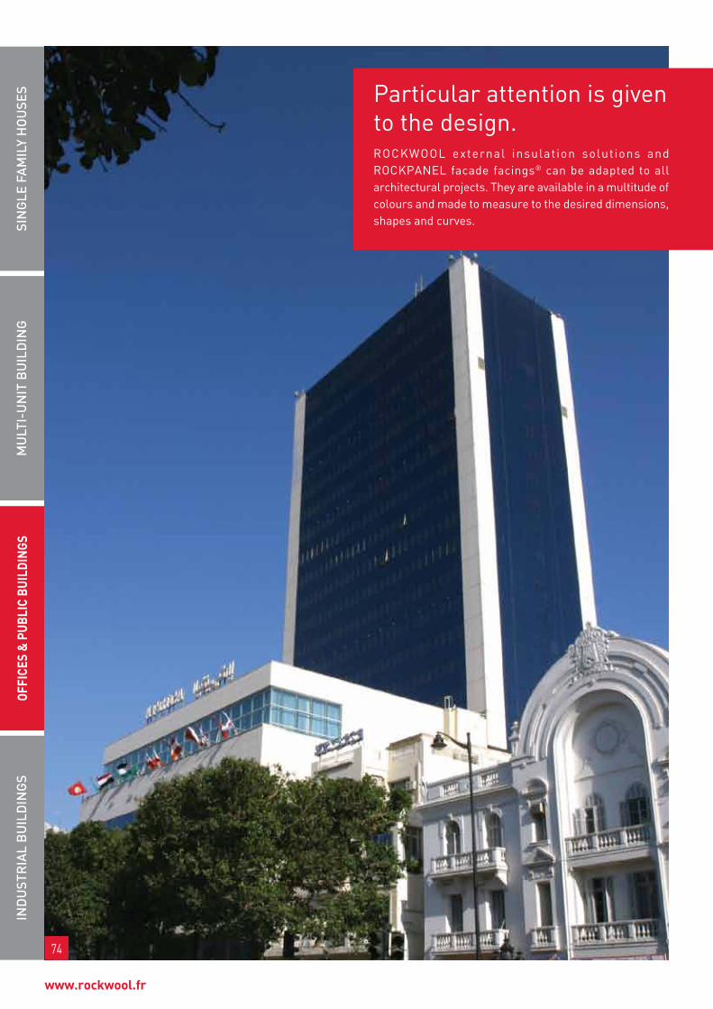
74
www.rockwool.fr
particular attention is given to the design.Rockwool external insulat ion solutions and RockpAnEl facade facings® can be adapted to all architectural projects. they are available in a multitude of colours and made to measure to the desired dimensions, shapes and curves.
InD
uSt
RIA
L B
uIL
DIn
gS
offI
CES
& p
ubLI
C bu
ILdI
ngS
Mu
LtI-
un
It B
uIL
DIn
gSI
ng
LE F
AM
ILy
Ho
uSE
S
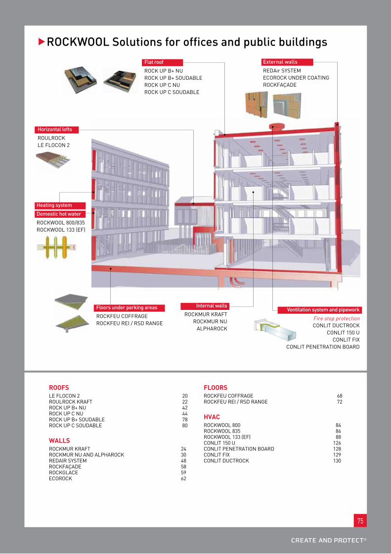
75
��RoCkWooL Solutions for offices and public buildings
Flat roof
Rock up b+ nu Rock up b+ souDAblE Rock up c nu Rock up c souDAblE
Floors under parking areas
RockfEu coffRAgERockfEu REI / RsD RAngE
Horizontal lofts
RoulRock lE flocon 2
Heating system
Domestic hot water
Rockwool 800/835Rockwool 133 (Ef)
Ventilation system and pipework
fire stop protection conlIt DuctRock
conlIt 150 uconlIt fIx
conlIt pEnEtRAtIon boARD
External walls
REDAir systEm EcoRock unDER coAtIng RockfAçADE
Internal walls
RockmuR kRAft RockmuR nu
AlpHARock
roofSlE flocon 2 20 RoulRock kRAft 22 Rock up b+ nu 42 Rock up c nu 44 Rock up b+ souDAblE 78 Rock up c souDAblE 80
wALLSRockmuR kRAft 24 RockmuR nu AnD AlpHARock 30 REDAIR systEm 48 RockfAçADE 58 RockglAcE 59 EcoRock 62
fLoorSRockfEu coffRAgE 68 RockfEu REI / RsD RAngE 72
HVACRockwool 800 84 Rockwool 835 86 Rockwool 133 (Ef) 88 conlIt 150 u 126 conlIt pEnEtRAtIon boARD 128 conlIt fIx 129 conlIt DuctRock 130

76
www.rockwool.fr
76
www.rockwool.fr
FIRE PERFoRMAnCE
Reaction to fire
performance not determined primary: Euroclass A1 - Incombustible
thicknesses (mm) RA RA,tr
bare slab 200 mm 61 57
Rock up b+ souDAblE 140 mm 64 (+3) 58
Rock up b+ souDAblE 140 mm + 5 cm gravel
71 (+10) 65 (+7)
Insulation
Ac12-26039828-1 slated Ac12-26039828-2 gravel
meets all airport, railway land and road land regulatory constraints. In addition, due to this high performance, these systems allow neighbours to be protected when loud noise is generated inside the building.
tHERMAL PERFoRMAnCE
ACouStIC PERFoRMAnCERoCkWooL RECoMMEnDAtIonS
Rt 2012: R = 3.55 m2.k/w - refer to the Rt2012 doc thk. 140 mm recommended
Rt-Existing: R = 2.55 m2.k/w - Rock up b+ souDAblE thk. 100 mm recommended
single layer
thickness (mm) 50 60 70 80 90 100
ResistanceresistanceR (m2.k/w)
1.25 1.50 1.75 2.05 2.30 2.55
single layer
thickness (mm) 110 120 130 140 150 160
ResistanceresistanceR (m2.k/w)
2.80 3.05 3.30 3.55 3.80 4.10
Double layer*
thickness (mm) 170 180 190 200 210 220 230 240 250 260
ResistanceresistanceR (m2.k/w)
4.30 4.60 4.85 5.10 5.35 5.60 5.85 6.10 6.35 6.65
* with 1st layer in Rock up b+ nu
roCk up b+ SoudAbLERockacier b+ soudable is a double density stone wool insulating panel, whose special feature is an increased density upper surface covered with a layer of bitumen and a thermo-fusible film.
roCk up b+ SoudAbLE
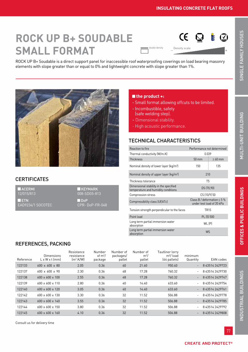
77
InD
uSt
RIA
L B
uIL
DIn
gS
Mu
LtI-
un
It B
uIL
DIn
gSI
ng
LE F
AM
ILy
Ho
uSE
SoF
FICE
S &
Pu
BLIC
Bu
ILDI
ngS
77
InD
uSt
RIA
L B
uIL
DIn
gS
offI
CES
& p
ubLI
C bu
ILdI
ngS
Mu
LtI-
un
It B
uIL
DIn
gSI
ng
LE F
AM
ILy
Ho
uSE
S
Rock up b+ soudable is a direct support panel for inaccessible roof waterproofing coverings on load bearing masonry elements with slope greater than or equal to 0% and lightweight concrete with slope greater than 1%.
roCk up b+ SoudAbLE SMALL forMAt Density scale
— +double density
REFEREnCES, PACkIng
CERtIFICAtES
tECHnICAL CHARACtERIStICS
the product +: - small format allowing offcuts to be limited.- Incombustible, safety
(safe welding step).- Dimensional stability.- High acoustic performance.
ACERMI kEyMARk 12/015/813 008-sDg5-813
Etn DoP EAD9234/1 socotEc cpR- Dop-fR-048
ReferenceDimensions
l x w x t (mm)
Resistanceresistance
(m2.k/w)
number of m2/
package
number of packages/
pallet
number of m2/
pallet
tautliner lorry m²/ load
(44 pallets)minimum
Quantity EAn codes
122133 600 x 600 x 80 2.05 0.36 60 21.60 950.40 - 8 43514 2429723
122137 600 x 600 x 90 2.30 0.36 48 17.28 760.32 - 8 43514 2429730
122138 600 x 600 x 100 2.55 0.36 48 17.28 760.32 - 8 43514 2429747
122139 600 x 600 x 110 2.80 0.36 40 14.40 633.60 - 8 43514 2429754
122140 600 x 600 x 120 3.05 0.36 40 14.40 633.60 - 8 43514 2429761
122142 600 x 600 x 130 3.30 0.36 32 11.52 506.88 - 8 43514 2429778
122143 600 x 600 x 140 3.55 0.36 32 11.52 506.88 - 8 43514 2429785
122144 600 x 600 x 150 3.80 0.36 32 11.52 506.88 - 8 43514 2429792
122145 600 x 600 x 160 4.10 0.36 32 11.52 506.88 - 8 43514 2429808
consult us for delivery time
Reaction to fire performance not determined
thermal conductivity (w/m.k) 0.039
thickness 50 mm ≥ 60 mm
nominal density of lower layer (kg/m3) 150 135
nominal density of upper layer (kg/m3) 210
thickness tolerance t5Dimensional stability in the specified temperature and humidity conditions Ds (70,90)
compression stress cs (10/y) 50
compressibility class (uEAtc) class b / deformation ≤ 5 % under test load of 20 kpa
tension strength perpendicular to the faces tR15
point load pl (5) 500long term partial immersion water absorption wl (p)
long term partial immersion water absorption ws
InSuLAtIng ConCrEtE fLAt roofS

78
www.rockwool.fr
78
www.rockwool.fr
roCk up C SoudAbLE
ADVAntAgES
DIMEnSIonS
roCk up C SoudAbLE
Rock up c soudable is a non load bearing insulation panel forming a direct support for waterproof coverings on flat and inclined roofs in accordance with Dtu 43.1:- inaccessible flat roofs*, including walkways- equipment flat roofs and equipment zones**,
excluding platform paths- green flat roofs (ttv) complying with the ttv
professional rules from the csfE***- photo-voltaic flat roofs.roCk up C Soudable cannot be employed in the french overseas departments (doM) (except in guyana).*Inaccessible roofs are roofs for which traffic is limited to their maintenance only.** Equipment roofs and equipment zones are roofs are roofs where traffic is due to the presence of equipment or installations needing frequent maintenance visits.*** Can be used on extensive or semi-extensive green flat roofs, with grade "4" root resistant waterproof coating, usage described in the coating specific AT (Technical Recommendation) or DTA.
FIELD oF APPLICAtIon
can be used in equipment zones and green and photovoltaic flat roofs complete waterproofing adhesion: the bituminous membrane is welded to the insulation panel, guaranteeing better cohesion of the laminate. the higher density part of the panels allows:
- easier application of overlapping single layer waterproof covering joints
- improved resistance to frequent passage thermal and acoustic performance Dimensional stability Rot proof
l. 1200 x w. 1000 mm l. 1200 x w. 600 mm
MECHAnICAL CHARACtERIStICS
weight characteristics
values for Rock up c soudable
single density double density
thickness (mm) 50 to 60 70 to 160
top face density(thk. ≈15 mm) (kg/m3) - 230 (average)
nominal density (kg/m3) 175 (average) 165 (average)
compressibility class (uEAtc) class c
compression stress at 10% ≥ 70 kpa
stone wool insulating panel, whose special feature is an increased density upper surface (from 70 mm thickness), coated with a layer of bitumen and a thermo-fusible film.
tHERMAL RESIStAnCE*
thk. (mm) 50 60 70 80 90 100 110 120
R (m2.k/w) 1.15 1.40 1.75 2.05 2.30 2.55 2.80 3.05
thk. (mm) 130 135 140 145 150 155 160
R (m2.k/w) 3.30 3.45 3.55 3.70 3.80 3.95 4.10
Minimum quantity: refer to the current price list.The black box shows the safe value corresponding to the RT 2005 regulatory minimum.
CERtIFICAtES
ACERMI kEyMARk 02/015/045 (double density) 008-sDg5-045 02/015/285 (single density) 008-sDg5-285
DoP cpR- Dop-fR-036
Density scale— +

79
InD
uSt
RIA
L B
uIL
DIn
gS
Mu
LtI-
un
It B
uIL
DIn
gSI
ng
LE F
AM
ILy
Ho
uSE
SoF
FICE
S &
Pu
BLIC
Bu
ILDI
ngS
79
InD
uSt
RIA
L B
uIL
DIn
gS
offI
CES
& p
ubLI
C bu
ILdI
ngS
Mu
LtI-
un
It B
uIL
DIn
gSI
ng
LE F
AM
ILy
Ho
uSE
S
InSuLAtIng ConCrEtE fLAt roofS
linear thermal expansion coefficient: 2 x 10-6.c-1.Residual deformation at 20° c: negligible.Dimensional variation at ambient temperature of 20 °c between 65 and 80 % RH: - longitudinal direction< 1 mm/m - transverse direction < 1 mm/mlow sensitivity to temperature and humidity variations.thickness expansion ≤ 5% (av. 2 %).water absorption with full immersion 11 to 12 % at 20 °c. after 7 days and saturation. Return to initial weight in 48 hrs.
DIMEnSIonAL StABILIty
Reaction to fire Euroclass f (no performance determined).the Rock up c soudable primary component(= Rock up c nu) is classed A1 (incombustible).
FIRE SAFEty
APPLICAtIon Inaccessible roofs
walkways
Heavy duty loose protection self protection
load bearing component slope (%) welded coatings subject to DtA* welded coatings subject to DtA*
masonry (1)0 to 5 fIt class "I4"
fIt class:"I4" in single layer system"I3" in double layer system
> 5 -
Autoclaved lightweight concrete (2)1 to 5 fIt class "I4"
> 5 -
Added protection by small prefabricated slabs self protection
load bearing component slope (%) welded coatings subject to DtA* welded coatings subject to DtA*
masonry (1)0 to 5 cf. Dtu 43.1
fIt class "I4"in single or double layer system
> 5 -
Autoclaved lightweight concrete (2)1 to 5 -
> 5 -

80
www.rockwool.fr
80
www.rockwool.fr
Extensive or semi-extensive green flat roofs
Root resistant coverings for garden flat roof subject to DtA*
load bearing component slope (%) (2) separate covering (2) bonded covering
masonry (1) 0 to 20fIt class "I5" fIt class "I5"
Autoclaved lightweight concrete (2) 1 to 20
FIT class: Puncture resistance (NF P 84 - 352) of waterproof covering (specific Technical Recommendations).(1) According to standard NF P 84 - 204 -1-1 (DTU 43.1) and Technical Recommendations(2) According to CSTB booklet 2192 of October 1987 and Technical Recommendations(3) With dry substrate weight > 68 kg/m2
(4) In accordance with TTV (Green roof) professional rules of the CSFE
WAtERPRooFIngRock up c soudable can be used in the following waterproofing systems:- self protected (slope up to 100 %):- in a single layer the panels are bonded onto the
vapour barrier either cold with fIx up glue (limited to a maximum wind suction of 3927 pa), or hot using EAc (Hot Applied coating) (limited to a maximum wind suction of 4712 pa);
- in multiple layers, the lower layers are made using Rock up c nu panels bonded to the support with EAc (Hot Applied coating) (at 1.2 kg/m2 minimum) or fIx up. the upper layer is made with Rock up c soudable panels bonded to the lower layer using EAc (Hot Applied coating).
Free laying of panels is excluded.bonding the waterproof coverings with EAc (Hot Applied coating) is prohibited.- other systems, consult the DtA*.the total thickness must not exceed 260 mm, consult the DtA*.the dimensions of the panels are those defined in Dtu 43.2, according to the radius of curvature (R) of the roof for panels bonded with EAc (Hot Applied coating), l ≤√R/100.Rock up c soudable panels must be laid in a chequered pattern, with the covered face upwards.the slopes and conditions of use for non-traditional waterproof coverings are defined in their individual DtAs*.
roCk up C SoudAbLE
flat equipment roofs
*DTA: Document Technique d’Application (Technical Application Document) or specific Avis Technique (Technical Recommendation).
Added protection by small prefabricated slabs self protection
load bearing component slope (%) welded coatings subject to DtA* welded coatings subject to DtA*
masonry (1)0 to 5 cf. Dtu 43.1
fIt class "I4"in single or double layer system
> 5 -
Autoclaved lightweight concrete (2)1 to 5 -
> 5 -
FIT class "I": Puncture resistance (NF P 84-352) of waterproof covering (specific DTA*).(1) To standards NF P 84-204 and NF P 84-205 (DTU 43.1 and DTU 43.2) and DTA*(2) According to CSTB booklet 2192 of October 1987 and DTA*The empty boxes correspond to excluded uses.

81
InD
uSt
RIA
L B
uIL
DIn
gS
Mu
LtI-
un
It B
uIL
DIn
gSI
ng
LE F
AM
ILy
Ho
uSE
SoF
FICE
S &
Pu
BLIC
Bu
ILDI
ngS
81
InD
uSt
RIA
L B
uIL
DIn
gS
offI
CES
& p
ubLI
C bu
ILdI
ngS
Mu
LtI-
un
It B
uIL
DIn
gSI
ng
LE F
AM
ILy
Ho
uSE
S
InSuLAtIng ConCrEtE fLAt roofS
reference documentsDecree no. 2006-592 of 24 may 2006 on building thermal characteristics and energy performance - J.o. (official Journal) of 25 may 2006. order of 24 may 2006 on the thermal characteristics of new buildings and new parts of buildings - J.o. of 25 may 2006.Decree no. 2007-363 of 19 march 2007 on feasibility studies of energy supplies, thermal specifications and energy performance of existing buildings and posting of the energy performance diagnostic report - J.o. (official Journal) of 21 march 2007. order of 3 may 2007 on thermal characteristics and energy performance of existing buildings. - J.o. of 17 may 2007.order of 22 february 2002, bringing into application for thermal insulation products manufactured for buildings decree no. 92-647 of 8 July 1992.Directive 89/106/cEE of the council of 21 December 1988 on the approximation of legislative, regulatory and administrative provisions of member states concerning construction products.standard nf En 13162, thermal insulation products for building, products manufactured from mineral wool.DtA* cstb n°5/08-2015Dtu 43.3 and 43.4.uEAtc technical guide.
InSurAnCEten-year civil Responsibility insurance policy for building material manufacturers, importers and equivalents, covering Rockwool france s.A.s. in application of the provisions of the law of January 4, 1978 and Article 1792-4 of the french civil code, to the exclusion of all installers’ guarantees.no reference to the name and brand of this product can be made in technical recommendations or technical documents without the written agreement of Rockwool france

82
www.rockwool.fr
82
www.rockwool.fr
roCkwooL 800
ADVAntAgES
roCkwooL 800
Apply the insulating shells well joined together with the longitudinal slot visible (towards the bottom or towards the front).
once correctly positioned close the shell using the self-adhesive lap. the ends should preferably be finished with an aluminium adhesive strip.
SuMMARy oF InStALLAtIon InStRuCtIonS
thermal and acoustic insulation fast, simple installation due to the notches and self-adhesive closure lap wide range of diameters and thicknesses for application on all types of metal and synthetic pipes Improves the fire behaviour of pipes, in particular for use in emergency exits, equipment rooms, movement areas compatible with stainless steel tubes long life well sized shape reducing losses at unions to a minimum short payback time
Rockwool 800 is a concentric stone wool shell with glass fibre reinforced aluminium foil and a self adhesive lap. this shell has been designed for thermal and acoustic insulation of heating pipes and sanitary pipes.
CERtIFICAtES
CERtIFICAt CE - noRME nF-En 14303 0751-cpD.2-008.0-01-01/12
DoP cpR- Dop-fR-060
tECHnICAL CHARACtERIStICS
performance standards
Reaction to fireDo ≤ 300 mm A2l-s1, d0Do > 300 mm A2-s1, d0
thermal conductivityt°c
λD(w/m.k)10
0.03420
0.03530
0.03650
0.039100
0.046150
0.056
thickness tolerance (mm) t9 (t8 if Do < 150)
chloride ions < 10 mg/kg
water vapour diffusion resistance mv2
water absorption ws(1)
maximum operating temperature 250°c
Resistivity to air flow > 5 kpa-s/m2
Implementation temperaturelimit the implementation temperature to 80°c -10°c to 50°c
Air thickness equivalent to the water vapour diffusion resistance sd ≥ 200 m En 12086
Do = External diameter

83
InD
uSt
RIA
L B
uIL
DIn
gS
Mu
LtI-
un
It B
uIL
DIn
gSI
ng
LE F
AM
ILy
Ho
uSE
SoF
FICE
S &
Pu
BLIC
Bu
ILDI
ngS
83
InD
uSt
RIA
L B
uIL
DIn
gS
offI
CES
& p
ubLI
C bu
ILdI
ngS
Mu
LtI-
un
It B
uIL
DIn
gSI
ng
LE F
AM
ILy
Ho
uSE
S
SHELL InSuLAtIon for pIpES
PACkIng AnD PACkAgES Quantity per package (loose) Quantity per pallet
Shell length: 1000 mm Packaged in boxes on pallets (12 boxes per 0.8 m x 1.2 m pallet) Shell packaged under shrink wrap film with 3 units on pallet (56 pallets per lorry) Shell individually packaged under shrink wrap film
Ø(mm)
Quantity in ml per package
thk. 20 mm thk. 25 mm thk. 30 mm thk. 40 mm thk. 50 mm thk. 60 mm
Qty. Qty. Qty. Qty. Qty. Qty.
18 42 30 25 - - -
22 36 30 20 13 9 -
28 30 25 20 12 9 -
35 25 20 16 9 7 5
42 20 16 12 9 6 4
48 16 15 12 9 6 4
54 16 12 9 8 5 4
57 15 12 9 6 5 4
60 12 11 9 6 5 4
64 12 9 9 6 4 1
70 11 9 8 5 4 1
76 9 9 7 5 4 1
83 9 7 6 5 3 1
89 9 6 6 4 3 1
102 - 5 4 4 3 1
108 - 5 4 3 3 1
114 - 4 4 3 3 1
121 - 4 3 3 3 -
127 - 4 3 3 3 3
133 - 3 3 3 3 1
140 - 3 3 3 3 1
159 - 3 3 3 1 -
169 - 3 3 3 1 1
178 - - - - - -
194 - 3 3 1 1 -
201 - 1 1 1 1 -
219 - 1 1 1 1 1
230 - - 1 1 1 -
245 - - 1 1 1 -
253 - - 1 1 1 -
267 - - 1 1 1 -
273 - - 1 1 1 1
305 - - 1 1 1 -
324 - - 1 1 1 -
Ø(mm)
Quantity in ml per pallet
thk. 20 mm thk. 25 mm thk. 30 mm thk. 40 mm thk. 50 mm thk. 60 mm
Qty. Qty. Qty. Qty. Qty. Qty.
18 504 360 300 - - -
22 432 360 240 156 108 -
28 360 300 240 144 108 -
35 300 240 192 108 84 -
42 240 192 144 108 72 -
48 192 180 144 108 72 -
54 192 144 108 96 60 -
57 180 144 108 72 60 -
60 144 132 108 72 60 48
64 144 108 108 72 48 48
70 132 108 96 60 48 33
76 108 108 84 60 48 30
83 108 84 72 60 36 -
89 108 72 72 48 33 27
102 - 60 48 48 28 24
108 - 60 48 33 25 23
114 - 48 48 32 25 20
121 - 48 36 30 24 -
127 - 48 33 27 23 -
133 - 36 32 25 24 17
140 - 33 30 24 20 16
159 - 25 25 20 - 14
169 - 25 22 19 - 12
178 - - - - - -
194 - - 17 - - -
201 - - - - - -
219 - - - - - -
230 - - - - - -
245 - - - - - -
253 - - - - - -
267 - - - - - -
273 - - - - - 6
305 - - - - - -
324 - - - - - -
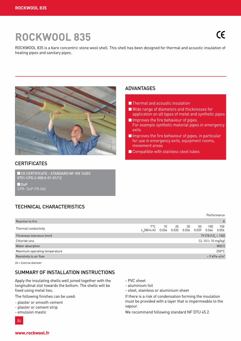
84
www.rockwool.fr
84
www.rockwool.fr
roCkwooL 835
ADVAntAgES
roCkwooL 835
Apply the insulating shells well joined together with the longitudinal slot towards the bottom. the shells will be fixed using metal ties.the following finishes can be used:- plaster or smooth cement - plaster or cement strip - emulsion mastic
- pvc sheet - aluminium foil - steel, stainless or aluminium sheetIf there is a risk of condensation forming the insulation must be provided with a layer that is impermeable to the vapour.we recommend following standard nf Dtu 45.2.
SuMMARy oF InStALLAtIon InStRuCtIonS
thermal and acoustic insulation wide range of diameters and thicknesses for application on all types of metal and synthetic pipes Improves the fire behaviour of pipes. for example synthetic material pipes in emergency exits Improves the fire behaviour of pipes, in particular for use in emergency exits, equipment rooms, movement areas compatible with stainless steel tubes
Rockwool 835 is a bare concentric stone wool shell. this shell has been designed for thermal and acoustic insulation of heating pipes and sanitary pipes.
CERtIFICAtES
CE CERtIFICAtE - StAnDARD nF-En 14303 0751-CPD.2-008.0-01-01/12
DoP cpR- Dop-fR-062
tECHnICAL CHARACtERIStICS
performance
Reaction to fire A
thermal conductivityt°c
λD(w/m.k)10
0.03420
0.03530
0.03650
0.039100
0.046150
0.056
thickness tolerance (mm) t9 (t8 if Do < 150)
chloride ions cl 10 (< 10 mg/kg)
water absorption ws(1)
maximum operating temperature 250°c
Resistivity to air flow > 5 kpa-s/m2
Do = External diameter

85
InD
uSt
RIA
L B
uIL
DIn
gS
Mu
LtI-
un
It B
uIL
DIn
gSI
ng
LE F
AM
ILy
Ho
uSE
SoF
FICE
S &
Pu
BLIC
Bu
ILDI
ngS
85
InD
uSt
RIA
L B
uIL
DIn
gS
offI
CES
& p
ubLI
C bu
ILdI
ngS
Mu
LtI-
un
It B
uIL
DIn
gSI
ng
LE F
AM
ILy
Ho
uSE
S
SHELL InSuLAtIon for pIpES
PACkIng AnD PACkAgES Quantity per package (loose)
Shell length: 1000 mm Packaged in boxes on pallets (12 boxes per 0.8 m x 1.2 m pallet) Shell packaged under shrink wrap film with 3 units on pallet (56 pallets per lorry) Shell individually packaged under shrink wrap film
Ø(mm)
Quantity in ml per package
thk. 25 mm thk. 30 mm thk. 40 mm thk. 50 mm thk. 60 mm
Qty. Qty. Qty. Qty. Qty.
18 30 25 - - -
22 30 20 13 9 6
28 25 20 12 9 6
35 20 16 9 7 5
42 16 12 9 6 4
48 15 12 9 6 4
54 12 9 8 5 4
57 12 9 6 5 4
60 11 9 6 5 4
64 9 9 6 4 3
70 9 8 5 4 3
76 9 7 5 4 3
83 7 6 5 3 3
89 6 6 4 3 3
102 5 4 4 3 3
108 5 4 3 3 3
114 4 4 3 3 3
121 4 3 3 3 3
127 4 3 3 3 3
133 3 3 3 3 3
140 3 3 3 3 1
159 3 3 3 1 1
169 3 3 3 1 1
194 3 3 1 1 1
219 1 1 1 1 1
230 1 1 1 1 1
245 1 1 1 1 1
267 1 1 1 1 1
273 1 1 1 1 1
305 1 1 1 1 1
324 1 1 1 1 1
Ø(mm)
Quantity in ml per pallet
thk. 25 mm thk. 30 mm thk. 40 mm thk. 50 mm thk. 60 mm
Qty. Qty. Qty. Qty. Qty.
18 360 300 - - -
22 360 240 156 108 72
28 300 240 144 108 72
35 240 192 108 84 60
42 192 144 108 72 48
48 180 144 108 72 48
54 144 108 96 60 48
57 144 108 72 60 48
60 132 108 72 60 48
64 108 108 72 48 36
70 108 96 60 48 33
76 108 84 60 48 30
83 84 72 60 36 -
89 72 72 48 33 27
102 60 48 48 28 24
108 60 48 33 25 23
114 48 48 32 25 20
121 48 36 30 24 20
127 48 33 27 23 19
133 36 32 25 24 17
140 33 30 24 20 -
159 25 25 20 - -
169 25 22 19 - -
194 - 17 - - -
219 - - - - -
230 - - - - -
245 - - - - -
267 - - - - -
273 - - - - -
305 - - - - -
324 - - - - -
Quantity per pallet

86
www.rockwool.fr
86
www.rockwool.fr
roCkwooL 133
ADVAntAgES
roCkwooL 133
cut the laminated mattresses to the correct length:- Round ducts:
(diameter + 2 x insulation thickness) x 3.14 + 30 mm- Rectangular ducts:
(perimeter + 8 x insulation thickness) + 30 mmfor ducts with flange unions it is advisable to apply the insulation to the exact length between the flange unions.
fix Rockwool 133 mechanically using bonded plugs, adhesive layer, flanges, etc. as chosen by the building owner.finish the longitudinal and transverse joints with a self-adhesive aluminium strip (minimum width 75 mm) applying it without wrinkles. providing free openings at duct unions is recommended.
SuMMARy oF InStALLAtIon InStRuCtIonS
thermal insulation keep constant insulation thickness, even in right angle corners Quick assembly Application in emergency exits, equipment ducts, etc., due to the optimum fire behaviour
Rockwool 133 insulating mattress comprises strips of stone wool with perpendicular fibres, bonded onto a glass fibre reinforced aluminium foil. this laminated mattress has been designed for external thermal insulation of ventilation ducts and also guarantees constant insulation thickness, even in the corners.
CERtIFICAtES
CE CERtIFICAtE - StAnDARD nF-En 14303 0751-CPD.2-007.0-02-01/12
DoP cpR- Dop-fR-063
Do = External diameter
tECHnICAL CHARACtERIStICS
performance standards
Reaction to fire A2l-s1, d0
thermal conductivityt°c
λD(w/m.k)10
0.04020
0.04230
0.04440
0.04650
0.048100
0.061150
0.076200
0.095250
0.122
thickness tolerance (mm) t4
water vapour diffusion resistance mv2
water absorption ws(1)
maximum operating temperature 250°c
smoke rating negligible En 6066
Density (nom.) 37 kg/m3
Air thickness equivalent to the water vapour diffusion resistance sd ≥ 200 m En 12086

87
InD
uSt
RIA
L B
uIL
DIn
gS
Mu
LtI-
un
It B
uIL
DIn
gSI
ng
LE F
AM
ILy
Ho
uSE
SoF
FICE
S &
Pu
BLIC
Bu
ILDI
ngS
87
InD
uSt
RIA
L B
uIL
DIn
gS
offI
CES
& p
ubLI
C bu
ILdI
ngS
Mu
LtI-
un
It B
uIL
DIn
gSI
ng
LE F
AM
ILy
Ho
uSE
S
tHErMAL And ACouStIC InSuLAtIon of VEntILAtIon duCtS
Rockwool laminated mattresses must be stored in their original packaging in a dry, frost free room.
StoRAgE
PACkIng In rolls
packaged under shrink wrap film 1 complete lorry = 400 rolls
on palletspackaged under shrink wrap film 1 complete lorry = 14 pallets
Referencethickness
(mm)length
(cm)width
(cm)m2 /roll
m3 /roll
minimum quantity(rolls)
31063 25 1,000 100 10 0.27 10
31064 30 800 100 8 0.27 10
31065 40 600 100 6 0.27 10
31066 50 500 100 5 0.27 10
31067 60 400 100 4 0.27 10
31081 70 350 100 3.5 0.27 10
31068 80 300 100 3 0.27 10
31069 100 250 100 2.5 0.27 10
Referencethickness
(mm)length
(cm)width
(cm)m2 /
palletm3 /
palletminimum quantity
(pallets)
57253 25 1,000 100 250 8.14 1
57255 30 800 100 200 8.14 1
60770 40 600 100 150 8.14 1
57257 50 500 100 125 8.14 1
60829 60 400 100 100 8.14 1
60830 80 300 100 75 8.14 1
60831 100 250 100 62.5 8.14 1

88
www.rockwool.fr
88
www.rockwool.fr
HArdroCk 2 nu
ADVAntAgES
DIMEnSIonS
HArdroCk 2 nu
HARDRock 2 nu is a non load bearing insulation panel forming a direct support for waterproof coverings on flat and inclined roofs of inaccessible flat roofs*, including walkways.these inaccessible flat roofs are composed of load bearing elements made from ribbed steel sheeting (excluding ‘wide span’ deck floors), in wood and derivatives, for slopes compliant with Dtu 43.3 and 43.4.HARDRock 2 nu is not intended to be applied on wide span steel decks, under vegetation, or under photovoltaic membranes.
*Inaccessible roofs are roofs for which traffic is limited to their maintenance only.
FIELD oF APPLICAtIon
Hard surface easing the construction of overlapping joints in single layer synthetic waterproof coverings greater resistance to punctures and repeated walking than traditional panels makes a distinct contribution to limiting point deformations of the synthetic membrane under static point loads Dimensional stability Reaction to fire: Euroclass A1 (incombustible) thermal and acoustic performance Rot proof
Available in these formats: - standard: l. 1200 x w. 1000 mm - gl: l. 2400 x w. 600 mm - gs: l. 2400 x w. 1200 mm
MECHAnICAL CHARACtERIStICS
weight characteristics values
thickness (mm) 50 to 160
Density of upper face (kg/m3) (thk. > 12 mm) 210 (average)
nominal density (kg/m3) 140 (average)
tension perpendicular to the faces class b / deformation ≤ 5 % under test load of 20 kpa
compression stress at 10% ≥ 50 kpa
bare stone wool insulating panel, whose special feature is an increased density upper surface indicated by marking. HARDRock 2 nu is intended for mechanically fixed single layer synthetic coverings.
tHERMAL RESIStAnCE*
thk. (mm) 50 55 60 65 70 75 80 85 90
R (m2.k/w) 1.25 1.40 1.50 1.65 1.75 1.90 2.05 2.15 2.30
thk. (mm) 95 100 105 110 115 120 125 130 135
R (m2.k/w) 2.40 2.55 2.65 2.80 2.90 3.05 3.20 3.30 3.45
thk. (mm) 140 145 150 155 160
R (m2,k/w) 3.55 3.70 3.80 3.95 4.10
Minimum quantity: refer to the current price list. Black box is the safe value corresponding to the regulatory minimum set by RT 2005 (in accordance with Th-U rules including included thermal bridges for four 4.8 mm diameter fastenings per m2).
CERtIFICAtES
ACERMI kEyMARk 04/015/295 008-sDg5-295
DoP cpR- Dop-fR-044

89
InD
uSt
RIA
L B
uIL
DIn
gS
Mu
LtI-
un
It B
uIL
DIn
gSI
ng
LE F
AM
ILy
Ho
uSE
SoF
FICE
S &
Pu
BLIC
Bu
ILDI
ngS
89
InD
uSt
RIA
L B
uIL
DIn
gS
offI
CES
& p
ubLI
C bu
ILdI
ngS
Mu
LtI-
un
It B
uIL
DIn
gSI
ng
LE F
AM
ILy
Ho
uSE
S
InSuLAtIng StEEL fLAt roofS
low sensitivity to temperature and humidity variations.Average thickness expansion 2% (< 5%) (test specimen maintained at 100°c for 15 min., 100% RH then cooled back to ambient temperature).water absorption with full immersion 2 to 3% after 24h at 20°c. saturation after 7 days and return to initial weight in 48 hrs.point load tests (pl) to standard nf En 12430[1] single density panel: RockAcIER b = pl (400)and RockAcIER c = pl (500)[2] HARDRock 2 nu dual density panel = pl (500)the higher density layer distinctly enlarges the distribution zone and improves the resistance of the synthetic waterproofing membrane under static point loading by about 50 %.
linear thermal expansion coefficient: 2 x 10⁻⁶.°c-.Residual shrinkage at 20 °c after 4 days at 70 °c: negligible.Dimensional variation on stabilisation at ambient temperature of 20 °c between 65 and 80 % RH:- longitudinal direction < 1 mm per m;- transverse direction < 1 mm per m.
DIMEnSIonAL StABILIty
APPLICAtIon Inaccessible roofs
walkways
loose protection self protection
load bearing component slope (%) synthetic covering under tecRec (or DtA*)
synthetic covering under tecRec (or DtA*), fixed mechanically
wood and wood derivatives(according to Dtu 43.4 and tecRec)
1 to 5 fIt class 4
l3and according to tecRec for the covering
> 5 -
Ribbed steel sheet(according to Dtu 43.3)
1 to 5 fIt class 4
> 5 -
4 = waterproof covering puncture resistance to NF 84.352. The empty boxes correspond to excluded uses
Heavy duty loose protection self protection
load bearing component slope (%) synthetic covering under tecRec (or DtA*)
synthetic covering under tecRec (or DtA*), fixed mechanically
wood and wood derivatives(according to Dtu 43.4 and tecRec)
1 to 5 fIt class 4
l4and according to tecRec for the covering
5 to 50 -
Ribbed steel sheet(according to Dtu 43.3)
3 to 5 fIt class 4
5 to 50 -
4 = waterproof covering puncture resistance to NF 84.352. The empty boxes correspond to excluded uses.
ACouStIC PERFoRMAnCE
productsRw (c;ctr) in db
RA RA,tr
tAn 75/100th + HARDRock 2 nu 120 mm+ synthetic waterproofing
36 (-1; -4)
35 32
1 2

90
www.rockwool.fr
90
www.rockwool.fr
HArdroCk 2 nu
ARRAngEMEntthe panels must be laid in a chequer board pattern (see Dtu 43.3 and 43.4). the continuous line of joints between panels must be perpendicular to the ribs of the steel sheeting (see Dtu 43.3).on components made from ribbed steel sheeting: under mechanically-fastened covering:
- on flat slopes, each HARDRock 2 nu panel receives a central fastening** beforehand (the final fastenings are those defined in the covering DtA*);
- on curved slopes, 4 prior fastenings are used per panel. the arrangements for using the panels are those defined in Dtu 43.3: l ≤ √R/50 (R = radius of curvature).
- separate covering backing: comply with the provisions of Dtu 43.3.
on load bearing elements made from wood or wood derivative panels: see Dtu 43.4.Installation in several layers: the joints of successive layers must not be superimposed.
reminder: all our DtAs* state that, to avoid damage due to frequent passage during work, the panels must be covered with a rigid protection, for example a wooden decking.
WAtERPRooFIngsingle-layer, synthetic waterproof coverings, fastened mechanically or laid free under loose protection, should be used, subject to specific technical Recommendations (At - Avis technique) or technical Application Documents (DtA) where they stipulate application on bare mineral wool.the enhanced puncture resistance requirements in fIt class "3" or "4" are shown in the tables on pages 2 and 3.
FIXIngS(1) on PRoFILE SHEEtSRefer to the individual technical Recommendation for the single layer synthetic waterproofing. "step-resistant" fastening assemblies with connectors and plates are used in accordance with the provisions of cstb sheet no. 3563 (June 2006) "wind resistance of waterproof coatings for roofs" and Dtu 43.3.
note: the diameter of usable screws is 4.8 mm for solid sheets and 6.3 mm for perforated or embossed metal sheets.
LIMItAtIonS on uSEApplications in accordance with the dtu and dtA *the limits on use of HARDRock 2 nu are those defined in Dtu 43.3, 43.4 and its specific technical Application Document.
n.b. : the DtA* for HARDRock 2 nu does not address load bearing components made from ribbed steel sheeting with a profile top opening > 70 mm. please refer to the RockvAllÉE technical datasheet for this application.
*DTA: Document Technique d’Application (Technical Application Document) or specific Avis Technique (Technical Recommendation)** Refer to the DTA for hARDROCK 2 Nu
91
InD
uSt
RIA
L B
uIL
DIn
gS
Mu
LtI-
un
It B
uIL
DIn
gSI
ng
LE F
AM
ILy
Ho
uSE
SoF
FICE
S &
Pu
BLIC
Bu
ILDI
ngS
91
InD
uSt
RIA
L B
uIL
DIn
gS
offI
CES
& p
ubLI
C bu
ILdI
ngS
Mu
LtI-
un
It B
uIL
DIn
gSI
ng
LE F
AM
ILy
Ho
uSE
S
InSuLAtIng StEEL fLAt roofS
reference documentsDecree no. 2006-592 of 24 may 2006 on building thermal characteristics and energy performance - J.o. (official Journal) of 25 may 2006. order of 24 may 2006 on the thermal characteristics of new buildings and new parts of buildings - J.o. of 25 may 2006.Decree no. 2007-363 of 19 march 2007 on feasibility studies of energy supplies, thermal specifications and energy performance of existing buildings and posting of the energy performance diagnostic report - J.o. (official Journal) of 21 march 2007. order of 3 may 2007 on thermal characteristics and energy performance of existing buildings. - J.o. of 17 may 2007.order of 22 february 2002, bringing into application for thermal insulation products manufactured for buildings decree no. 92-647 of 8 July 1992.Directive 89/106/cEE of the council of 21 December 1988 on the approximation of legislative, regulatory and administrative provisions of member states concerning construction products.standard nf En 13162, thermal insulation products for building, products manufactured from mineral wool.DtA* cstb no. 5/11-2191.Dtu 43.3 and 43.4.
InSurAnCEten-year civil Responsibility insurance policy for building material manufacturers, importers and equivalents, covering Rockwool france s.A.s. in application of the provisions of the law of January 4, 1978 and Article 1792-4 of the french civil code, to the exclusion of all installers’ guarantees.no reference to the name and brand of this product can be made in technical recommendations or technical documents without the written agreement of Rockwool france
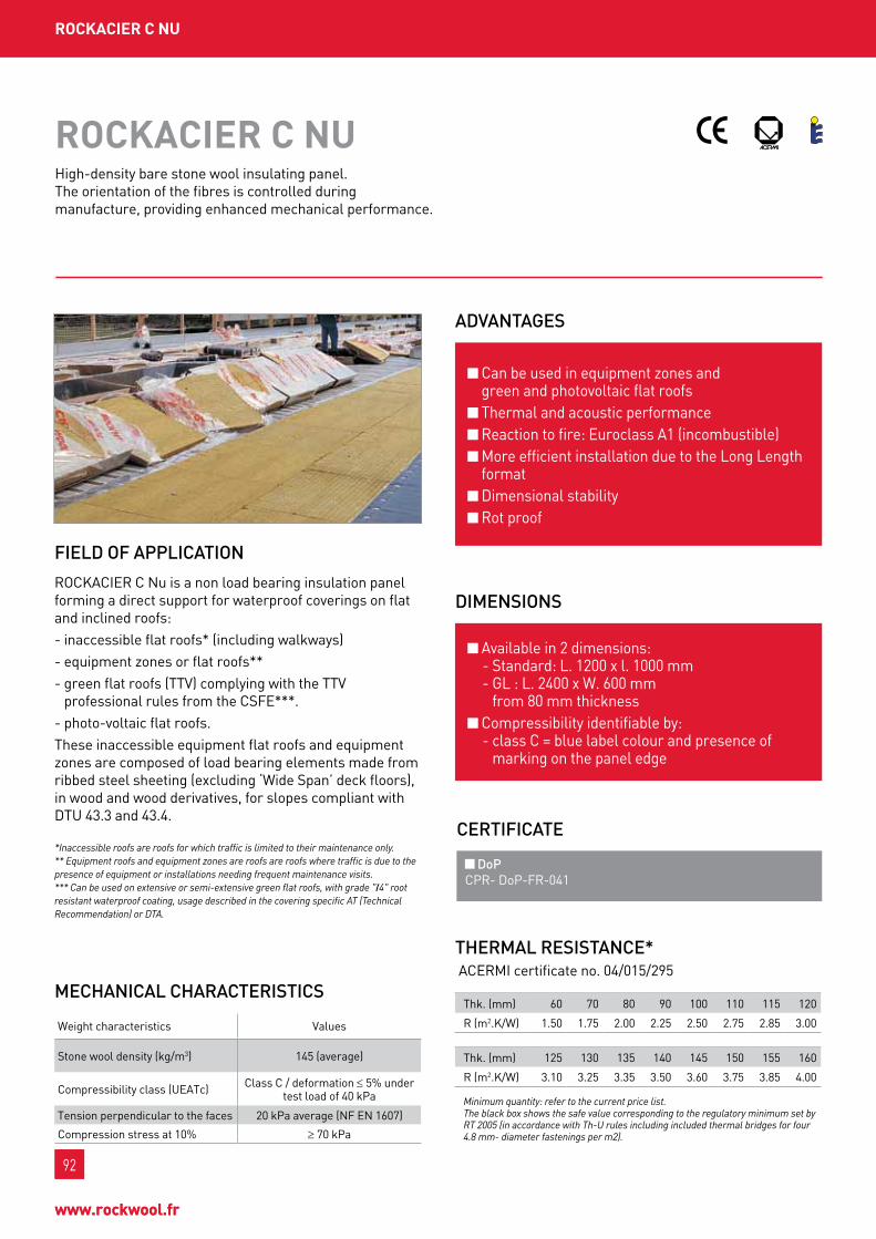
92
www.rockwool.fr
92
www.rockwool.fr
roCkACIEr C nu
ADVAntAgES
DIMEnSIonS
roCkACIEr C nu
RockAcIER c nu is a non load bearing insulation panel forming a direct support for waterproof coverings on flat and inclined roofs:- inaccessible flat roofs* (including walkways)- equipment zones or flat roofs**- green flat roofs (ttv) complying with the ttv
professional rules from the csfE***.- photo-voltaic flat roofs.these inaccessible equipment flat roofs and equipment zones are composed of load bearing elements made from ribbed steel sheeting (excluding ‘wide span’ deck floors), in wood and wood derivatives, for slopes compliant with Dtu 43.3 and 43.4.
*Inaccessible roofs are roofs for which traffic is limited to their maintenance only.** Equipment roofs and equipment zones are roofs are roofs where traffic is due to the presence of equipment or installations needing frequent maintenance visits.*** Can be used on extensive or semi-extensive green flat roofs, with grade "I4" root resistant waterproof coating, usage described in the covering specific AT (Technical Recommendation) or DTA.
FIELD oF APPLICAtIon
can be used in equipment zones and green and photovoltaic flat roofs thermal and acoustic performance Reaction to fire: Euroclass A1 (incombustible) more efficient installation due to the long length format Dimensional stability Rot proof
Available in 2 dimensions: - standard: l. 1200 x l. 1000 mm - gl : l. 2400 x w. 600 mm
from 80 mm thickness compressibility identifiable by:
- class c = blue label colour and presence of marking on the panel edge
MECHAnICAL CHARACtERIStICS
weight characteristics values
stone wool density (kg/m3) 145 (average)
compressibility class (uEAtc) class c / deformation ≤ 5% under test load of 40 kpa
tension perpendicular to the faces 20 kpa average (nf En 1607)
compression stress at 10% ≥ 70 kpa
High-density bare stone wool insulating panel. the orientation of the fibres is controlled during manufacture, providing enhanced mechanical performance.
tHERMAL RESIStAnCE* AcERmI certificate no. 04/015/295
thk. (mm) 60 70 80 90 100 110 115 120
R (m2.k/w) 1.50 1.75 2.00 2.25 2.50 2.75 2.85 3.00
thk. (mm) 125 130 135 140 145 150 155 160
R (m2.k/w) 3.10 3.25 3.35 3.50 3.60 3.75 3.85 4.00
Minimum quantity: refer to the current price list.The black box shows the safe value corresponding to the regulatory minimum set by RT 2005 (in accordance with Th-U rules including included thermal bridges for four 4.8 mm- diameter fastenings per m2).
CERtIFICAtE
DoP cpR- Dop-fR-041

93
InD
uSt
RIA
L B
uIL
DIn
gS
Mu
LtI-
un
It B
uIL
DIn
gSI
ng
LE F
AM
ILy
Ho
uSE
SoF
FICE
S &
Pu
BLIC
Bu
ILDI
ngS
93
InD
uSt
RIA
L B
uIL
DIn
gS
offI
CES
& p
ubLI
C bu
ILdI
ngS
Mu
LtI-
un
It B
uIL
DIn
gSI
ng
LE F
AM
ILy
Ho
uSE
S
InSuLAtIng StEEL fLAt roofS
linear thermal expansion coefficient: 2 x 10⁻⁶.°c-1.Residual shrinkage at 20 °c after 4 days at 70 °c: negligible.Dimensional variation on stabilisation at ambient temperature of 20°c between 65 and 80 % RH: – longitudinal direction < 1 mm/m – transverse direction < 1 mm/m
low sensitivity to temperature and humidity variations.Average thickness expansion 2% (< 5%) (test specimen maintained at 100°c for 15 min, 100% RH then cooled back to ambient temperature).water absorption with full immersion 11 to 12% at 20 °c after 7 days and saturation. Return to initial weight in 48 hrs.
DIMEnSIonAL StABILIty
APPLICAtIon Inaccessible roofs
walkways
Heavy duty loose protection self protection
load bearing component slope (%) covering subject to DtA*covering subject to DtA*
bonded using EAc (Hot Applied coating)
covering subject to DtA*mechanically fixed (1)
wood and wood derivatives(according to Dtu 43.4 and DtA*)
≤ 5 (cf. Dtu 43.4) I3 if two layerI4 if single layer
I2 if two layerwith R ≤ 2 m2.k/w
I3 if two layerwith R > 2 m2.k/wI4 if single layer
l3and according to DtA*
for the covering
> 5 -
Ribbed steel sheets(according to nf Dtu 43.3 and DtA*)
3 to 5 I3 if two layerI4 if single layer
> 5 -
protection by small slabs self protection
load bearing component slope (%) covering subject to DtA*covering subject to DtA*
bonded using EAc (Hot Applied coating)
covering subject to DtA*mechanically fixed (1)
wood and wood derivatives (to nf Dtu 43.4 and DtA*)
≤ 5 (cf. Dtu 43.4) I4
I4l4
and according to DtA*for the covering
5 to 50 -Ribbed steel sheets(according to nf Dtu 43.3 and DtA*)
3 to 5 I4
5 to 50 -
(1) Step Resistant fixings

94
www.rockwool.fr
94
www.rockwool.fr
Equipment zones
Extensive or semi-extensive green flat roofs
protection by small slabs self protection
load bearing component slope (%) covering subject to DtA*covering subject to DtA*
bonded using EAc (Hot Applied coating)
covering subject to DtA*mechanically fixed (1)
wood and wood derivatives(according to Dtu 43.4 and DtA*)
≤ 5 (cf. Dtu 43.4) I4
I4 l4 and according to DtA* for the covering
> 5 -
Ribbed steel sheets(according to nf Dtu 43.3 and DtA*) 3 to 5 I4
Root resistant coverings for garden flat roof subject to DtA*
load bearing component slope (%) separate covering (3) bonded covering
Ribbed steel sheeting (cf. dtu 43.3) 3 to 20 fIt class "Is" fIt class "Igs"
R = Effective Thermal Resistance. : Waterproof covering FIT class (specific DTA*). L = Static puncture resistance sub-class.(1) Step Resistant fixings(3) With dry substrate weight > 66 kg/m2
(4) In accordance with TTV (Green roof) professional rules of the CSFEThe empty boxes correspond to excluded uses.
roCkACIEr C nu
the panels must be laid in a chequer board pattern (see Dtu 43.3 and 43.4). the continuous line of joints between panels must be perpendicular to the ribs of the steel sheeting (see Dtu 43.3).on components made from ribbed steel sheeting: under mechanically-fastened covering:
- on flat slopes, each RockAcIER c nu panel receives a central fixing** beforehand (the final fixings are those defined in the covering DtA*);
- on curved slopes, four prior fastenings are used per panel. the arrangements for using the panels are those defined in Dtu 43.3: l ≤ √R/50 (R = radius of curvature).
coating backing separate or EAc (Hot Applied coating) bonded: comply with the requirements of Dtu 43.3.on load bearing elements made from wood or wood derivative panels: see Dtu 43.4.Installation in several layers: the joints of successive layers must not be superimposed.
reminder: all our DtAs* state that, to avoid damage due to frequent passage during work, the panels must be covered with a rigid protection, for example a wooden decking.
ARRAngEMEnt
*DTA: Document Technique d’Application (Technical Application Document) or specific Avis Technique (Technical Recommendation)** Refer to the DTA for ROCKACIER C Nu
95
InD
uSt
RIA
L B
uIL
DIn
gS
Mu
LtI-
un
It B
uIL
DIn
gSI
ng
LE F
AM
ILy
Ho
uSE
SoF
FICE
S &
Pu
BLIC
Bu
ILDI
ngS
95
InD
uSt
RIA
L B
uIL
DIn
gS
offI
CES
& p
ubLI
C bu
ILdI
ngS
Mu
LtI-
un
It B
uIL
DIn
gSI
ng
LE F
AM
ILy
Ho
uSE
S
InSuLAtIng StEEL fLAt roofS
WAtERPRooFIngnon-traditional coverings are applied according to the methods defined in their respective DtAs*. traditional coverings are those described in Dtu series 43, according to the slopes and conditions of use in the standard.
FIXIngSthese fixings are ‘step Resistant’ and comply with cstb booklet no.3563. the final fixings are those defined in the specific At (technical Recommendation) or DtA* for the waterproof coating. note: the diameter of usable screws is 4.8 mm for solid sheets and 6.3 mm for perforated or embossed metal sheets.
LIMItAtIonS on uSEApplications in accordance with the dtu and dtA *the limits on use of RockAcIER c nu are those defined in Dtu 43.3, 43.4 and its specific technical Application Document.
n.b. : the DtA* for RockAcIER c nu does not address load bearing components made from ribbed steel sheet-ing with a profile top opening > 70 mm. please refer to the RockvAllÉE technical datasheet for this application (thk. ≤ 95 mm).
reference documentsDecree no. 2006-592 of 24 may 2006 on building thermal characteristics and energy performance - J.o. (official Journal) of 25 may 2006. order of 24 may 2006 on the thermal characteristics of new buildings and new parts of buildings - J.o. of 25 may 2006.Decree no. 2007-363 of 19 march 2007 on feasibility studies of energy supplies, thermal specifications and energy performance of existing buildings and posting of the energy performance diagnostic report - J.o. (official Journal) of 21 march 2007. order of 3 may 2007 on thermal characteristics and energy performance of existing buildings. - J.o. of 17 may 2007.order of 22 february 2002, bringing into application for thermal insulation products manufactured for buildings decree no. 92-647 of 8 July 1992.Directive 89/106/cEE of the council of 21 December 1988 on the approximation of legislative, regulatory and administrative provisions of member states concerning construction products.standard nf En 13162, thermal insulation products for building, products manufactured from mineral wool.DtA* cstb no. 5/11-2183.Dtu 43.3 and 43.4.uEAtc technical guide.
InSurAnCEten year public liability insurance policy for construction material manufacturers, importers and similar guaranteeing the company Rockwool france s.A.s. in application of the provisions provided by the law of 4 January 1978 and article 1792-4 of the french civil code, to the exclusion of all installers' guarantees.no reference to the name and brand of this product can be made in technical recommendations or technical documents without the written agreement of Rockwool france

96
www.rockwool.fr
Industrial and commercial buildings represent a large part of new construction. they are arranged around production cells, offices, exhibition halls or storage zones for the largest.
the design of such buildings necessitates a broad constructive approach depending on the construction project and the regulatory environment, whilst controlling the economic impact.
A high quality building will always take the safety and comfort of those working in it into account.
Ind
uSt
rIA
L b
uIL
dIn
gS
oFFI
CES
& P
uBL
IC B
uIL
DIn
gSM
uLt
I-u
nIt
Bu
ILD
Ing
SIn
gLE
FA
MIL
y H
ou
SES
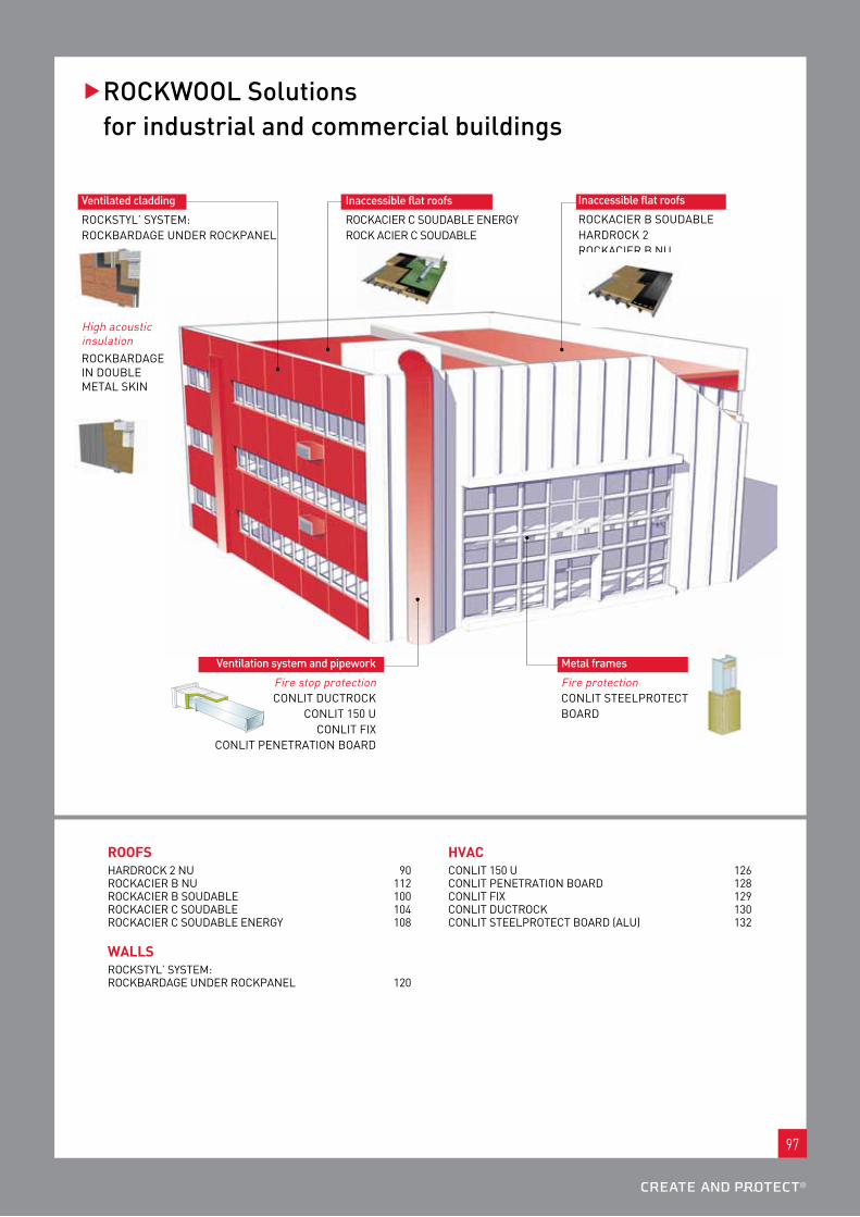
97
��RoCkWooL Solutions for industrial and commercial buildings
Ventilated cladding
Rockstyl’ systEm: RockbARDAgE unDER RockpAnEl
High acoustic insulationRockbARDAgE In DoublE mEtAl skIn
Inaccessible flat roofs
RockAcIER b souDAblE HARDRock 2 RockAcIER b nu
Inaccessible flat roofs
RockAcIER c souDAblE EnERgy Rock AcIER c souDAblE
Ventilation system and pipework
fire stop protection conlIt DuctRock
conlIt 150 u conlIt fIx
conlIt pEnEtRAtIon boARD
Metal frames
fire protection conlIt stEElpRotEct boARD
roofSHARDRock 2 nu 90 RockAcIER b nu 112 RockAcIER b souDAblE 100 RockAcIER c souDAblE 104 RockAcIER c souDAblE EnERgy 108
wALLSRockstyl’ systEm: RockbARDAgE unDER RockpAnEl 120
HVACconlIt 150 u 126 conlIt pEnEtRAtIon boARD 128 conlIt fIx 129 conlIt DuctRock 130 conlIt stEElpRotEct boARD (Alu) 132

98
www.rockwool.fr
98
www.rockwool.fr
roCkACIEr b SoudAbLE
ADVAntAgES
DIMEnSIonS
roCkACIEr b SoudAbLE
RockAcIER b soudable is a bitumen covered non load bearing panel forming a direct support for waterproof coverings on flat and inclined roofs of inaccessible flat roofs*, including walkways.these flat roofs are composed of load bearing elements made from ribbed steel sheeting, in wood and derivatives, for slopes compliant with Dtu 43.3 and 43.4.RockAcIER b soudable is not intended to be applied on wide span steel decks, under vegetation, or under photovoltaic or synthetic membranes.roCkACIEr b Soudable cannot be employed in the french overseas departments (doM) (except in guyana).
*Inaccessible roofs are roofs for which traffic is limited to their maintenance only.
FIELD oF APPLICAtIon
complete adhesion of the welded waterproofing to the bitumen covered insulation panel, guaranteeing better cohesion of the laminate thermal and acoustic performance Excellent mechanical strength due to straightened fibres Dimensional stability Rot proof
l. 1200 mm x w. 1000 mm compressibility identifiable by: - class b = blue label colour and presence of
marking on the panel edge
MECHAnICAL CHARACtERIStICS
weight characteristics values
covering area density ≈ 1000 g/m3
thickness (mm) 40 to 45 50 to 80
stone wool density (kg/m3) 157 (average) 135 (average)
compressibility class (uEAtc) class b / deformation ≤ 5% under test load of 20 kpa
tension perpendicular to the faces 20 kpa average (nf En 1607)
compression stress at 10% ≥ 50 kpa
High-density stone wool insulating panel, covered with a layer of bitumen and a thermo-fusible film.
tHERMAL RESIStAnCE* AcERmI certificate no. 02/015/019
thk. (mm) 40 45 50 55 60 70 75 80
R (m2.k/w) 1.00 1.15 1.25 1.40 1.50 1.75 1.90 2.05
Minimum quantity: refer to the current price list.To comply with RT 2005, the ROCKACIER B Soudable panelsmust be combined with a 1st layer of ROCKACIER B Soudable.
CERtIFICAtES
ACERMI kEyMARk
CE DoP cpR- Dop-fR-040

99
oFFI
CES
& P
uBL
IC B
uIL
DIn
gSM
uLt
I-u
nIt
Bu
ILD
Ing
SIn
gLE
FA
MIL
y H
ou
SES
InD
uSt
RIA
L B
uIL
DIn
gS
99
Ind
uSt
rIA
L b
uIL
dIn
gS
oFFI
CES
& P
uBL
IC B
uIL
DIn
gSM
uLt
I-u
nIt
Bu
ILD
Ing
SIn
gLE
FA
MIL
y H
ou
SES
InSuLAtIng StEEL fLAt roofS
linear thermal expansion coefficient: 2 x 10⁻⁶.°c-1.Residual shrinkage at 20 °c after 4 days at 70 °c: negligible.Dimensional variation on stabilisation at ambient temperature of 20 °c between 65 and 80 % RH: - longitudinal direction < 1 mm/m - transverse direction < 1 mm/mlow sensitivity to temperature and humidity variations.Average thickness expansion 2% (< 5%) (test specimen held for 15 min at 100 °c, 100% RH then cooled to ambient temperature).water absorption with full immersion 11 to 12 % at 20 °c after 7 days and saturation. Return to initial weight in 48 hrs.
Reaction to fire Euroclass f (no performance determined).the RockAcIER b soudable primary component (= RockAcIER b nu) is classed A1 (incombustible).buildings open to the public: favourable opinion of the central safety committee (commission centrale de sécurité) on 03/11/05.
DIMEnSIonAL StABILItyFIRE SAFEty
APPLICAtIon Inaccessible roofs
walkways
Heavy duty loose protection self protection
load bearing component slope (%) covering subject to DtA*(1) covering subject to DtA*(1)
wood and wood derivatives (to nf Dtu 43.4 and DtA*)
(cf. Dtu 43.4) fIt class 3 (*)fIt class:
2 if two layer with R ≤ 2 m2.k/w3 if two layer with R > 2 m2.k/w
4 if single layer
> 5 -Ribbed steel sheets(according to nf Dtu 43.3 and DtA*)
(cf. Dtu 43.3) and ≤ 5 fIt class 3 (*)
> 5 -
Heavy duty loose protection self protection
load bearing component slope (%) covering subject to DtA*(1) covering subject to DtA*(1)
wood and wood derivatives (to nf Dtu 43.4 and DtA*)
(cf. Dtu 43.4) fIt class 4
fIt class 45 to 50 -
Ribbed steel sheets(according to nf Dtu 43.3 and DtA*)
(cf. Dtu 43.3) and ≤ 5 fIt class 4
5 to 50 -
R = Effective Thermal Resistance. R punct: static puncture resistance. (1) Step Resistant fixings. FIT Class = Puncture resistance (NF P 84-352) of waterproof covering (specific DTA*). *DTA: Document Technique d’Application (Technical Application Document) or specific Avis Technique (Technical Recommendation). The empty boxes correspond to excluded uses.
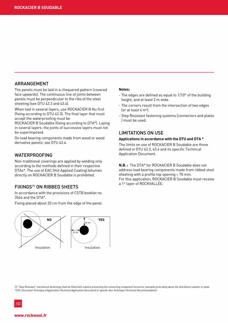
100
www.rockwool.fr
100
www.rockwool.fr
roCkACIEr b SoudAbLE
ARRAngEMEntthe panels must be laid in a chequered pattern (covered face upwards). the continuous line of joints between panels must be perpendicular to the ribs of the steel sheeting (see Dtu 43.3 and 43.4).when laid in several layers, use RockAcIER b nu first (fixing according to Dtu 43.3). the final layer that must accept the waterproofing must be RockAcIER b soudable (fixing according to DtA*). laying in several layers: the joints of successive layers must not be superimposed.on load bearing components made from wood or wood derivative panels: see Dtu 43.4.
WAtERPRooFIngnon-traditional coverings are applied by welding only according to the methods defined in their respective DtAs*. the use of EAc (Hot Applied coating) bitumen directly on RockAcIER b soudable is prohibited.
FIXIngS(1) on RIBBED SHEEtSIn accordance with the provisions of cstb booklet no. 3564 and the DtA*.fixing placed about 20 cm from the edge of the panel.
notes:- the edges are defined as equal to 1/10th of the building
height, and at least 2 m wide.- the corners result from the intersection of two edges
(or at least 4 m2).- step Resistant fastening systems (connectors and plates
) must be used.
LIMItAtIonS on uSEApplications in accordance with the dtu and dtA *the limits on use of RockAcIER b soudable are those defined in Dtu 43.3, 43.4 and its specific technical Application Document.
n.b. : the DtA* for RockAcIER b soudable does not address load bearing components made from ribbed steel sheeting with a profile top opening > 70 mm. for this application, RockAcIER b soudable must receive a 1st layer of RockvAllÉE.
(1) "Step Resistant" mechanical fastenings shall be fitted with a device preventing the connecting component (screw for example) protruding above the distribution washer or plate.*DTA: Document Technique d’Application (Technical Application Document) or specific Avis Technique (Technical Recommendation)
Insulation
no
Insulation
yES

101
oFFI
CES
& P
uBL
IC B
uIL
DIn
gSM
uLt
I-u
nIt
Bu
ILD
Ing
SIn
gLE
FA
MIL
y H
ou
SES
InD
uSt
RIA
L B
uIL
DIn
gS
101
Ind
uSt
rIA
L b
uIL
dIn
gS
oFFI
CES
& P
uBL
IC B
uIL
DIn
gSM
uLt
I-u
nIt
Bu
ILD
Ing
SIn
gLE
FA
MIL
y H
ou
SES
InSuLAtIng StEEL fLAt roofS
reference documentsDecree no. 2006-592 of 24 may 2006 on building thermal characteristics and energy performance - J.o. (official Journal) of 25 may 2006. order of 24 may 2006 on the thermal characteristics of new buildings and new parts of buildings - J.o. of 25 may 2006.Decree no. 2007-363 of 19 march 2007 on feasibility studies of energy supplies, thermal specifications and energy performance of existing buildings and posting of the energy performance diagnostic report - J.o. (official Journal) of 21 march 2007. order of 3 may 2007 on thermal characteristics and energy performance of existing buildings. - J.o. of 17 may 2007.order of 22 february 2002, bringing into application for thermal insulation products manufactured for buildings decree no. 92-647 of 8 July 1992.Directive 89/106/cEE of the council of 21 December 1988 on the approximation of legislative, regulatory and administrative provisions of member states concerning construction products.standard nf En 13162, thermal insulation products for building, products manufactured from mineral wool.DtA* cstb no. 5/12-2275.Dtu 43.3 and 43.4.
InSurAnCEten-year civil Responsibility insurance policy for building material manufacturers, importers and equivalents, covering Rockwool france s.A.s. in application of the provisions of the law of January 4, 1978 and Article 1792-4 of the french civil code, to the exclusion of all installers’ guarantees.no reference to the name and brand of this product can be made in technical recommendations or technical documents without the written agreement of Rockwool france

102
www.rockwool.fr
102
www.rockwool.fr
roCkACIEr C SoudAbLE
ADVAntAgES
DIMEnSIonS
roCkACIEr C SoudAbLE
RockAcIER c soudable is a bitumen covered non load bearing panel forming a direct support for waterproof coverings on flat and inclined roofs:- inaccessible flat roofs* (including walkways)- equipment zones or flat roofs**- green flat roofs (ttv) complying with the ttv
professional rules from the csfE***- photo-voltaic flat roofs.these inaccessible equipment flat roofs and equipment zones are composed of load bearing elements made from ribbed steel sheeting (excluding "wide span" deck floors), in wood and wood derivatives, for slopes compliant with Dtu 43.3 and 43.4.roCkACIEr C Soudable cannot be employed in the french overseas departments (doM) (except in guyana).
*Inaccessible roofs are roofs for which traffic is limited to their maintenance only.** Equipment roofs and equipment zones are roofs are roofs where traffic is due to the presence of equipment or installations needing frequent maintenance visits.*** Can be used on extensive or semi-extensive green flat roofs, with grade "4" root resistant waterproof coating, usage described in the coating specific AT (Technical Recommendation) or DTA.
FIELD oF APPLICAtIon
can be used in equipment zones and green and photovoltaic flat roofs complete adhesion of the welded waterproofing to the bitumen covered insulation panel, guaranteeing better cohesion of the laminate thermal and acoustic performance Dimensional stability Rot proof use in buildings open to the public covered by DtA no. 5/06-1883
l. 1200 mm x w. 1000 mm compressibility identifiable by: - class c = blue label colour and presence of
marking on the panel edge
MECHAnICAL CHARACtERIStICS
weight characteristics values
stone wool density (kg/m3) 145
covering area density 800 g/m2 minimum
compressibility class (uEAtc) class c
tension perpendicular to the faces 20 kpa average (nf En 1607)
compression stress at 10% ≥ 70 kpa
High-density stone wool insulating panel, covered with a layer of bitumen and a thermo-fusible film. the orientation of the fibres is controlled during manufacture, providing enhanced mechanical performance.
tHERMAL RESIStAnCE* AcERmI certificate no. 02/015/013
thk. (mm) 60 70 80 90 100 110 115 120
R (m2.k/w) 1.50 1.75 2.00 2.25 2.50 2.75 2.85 3.00
thk. (mm) 125 130 135 140 145 150 155 160
R (m2.k/w) 3.10 3.25 3.35 3.50 3.60 3.75 3.85 4.00
Minimum quantity: refer to the current price list.The black box shows the safe value corresponding to the regulatory minimum set by RT 2005 (in accordance with Th-U rules including included thermal bridges for four 4.8 mm- diameter fastenings per m2).
CERtIFICAtES
ACERMI kEyMARk
CE DoP cpR- Dop-fR-042

103
oFFI
CES
& P
uBL
IC B
uIL
DIn
gSM
uLt
I-u
nIt
Bu
ILD
Ing
SIn
gLE
FA
MIL
y H
ou
SES
InD
uSt
RIA
L B
uIL
DIn
gS
103
Ind
uSt
rIA
L b
uIL
dIn
gS
oFFI
CES
& P
uBL
IC B
uIL
DIn
gSM
uLt
I-u
nIt
Bu
ILD
Ing
SIn
gLE
FA
MIL
y H
ou
SES
InSuLAtIng StEEL fLAt roofS
linear thermal expansion coefficient: 2 x 10⁻⁶.°c-1.Residual shrinkage at 20°c after 4 days at 70°c: negligible.Dimensional variation on stabilisation at ambient temperature of 20°c between 65 and 80 % RH: - longitudinal direction< 1 mm/m - transverse direction < 1 mm/mlow sensitivity to temperature and humidity variations.Average thickness expansion 2% (< 5%) (test specimen held for 15 min at 100 °c, 100% RH then cooled to ambient temperature).water absorption with full immersion 11 to 12 % at 20°c after 7 days and saturation. Return to initial weight in 48 hrs.
DIMEnSIonAL StABILIty
APPLICAtIon Inaccessible roofs
walkways
Reaction to fire Euroclass f (no performance determined).the RockAcIER b soudable primary component (= RockAcIER c nu) is classed A1 (incombustible)buildings open to the public: favourable opinion of the central safety committee (commission centrale de sécurité) on 3/11/05.
FIRE SAFEty
Heavy duty loose protection self protection
load bearing component slope (%) covering subject to DtA* covering subject to DtA*
wood and wood derivatives(according to Dtu 43.4 and DtA*)
≤ 5 (cf. Dtu 43.4) I3 if two layer / I4 if single layerI2 if two layer with R ≤ 2 m2.k/wI3 if two layer with R ≤ 2 m2.k/w
I4 if single layer
> 5 -
Ribbed steel sheet(according to Dtu 43.3 and DtA*)
3 to 5 I3 if two layer / I4 if single layer
> 5 -R: Effective thermal Resistance. : waterproof covering fIt class (specific DtA*).*DtA: Document technique d’Application (technical Application Document) or specific Avis technique (technical Recommendation).
the empty boxes correspond to excluded uses.
Heavy duty loose protection self protection
load bearing component slope (%) covering subject to DtA* covering subject to DtA*
wood and wood derivatives(according to Dtu 43.4 and DtA*)
≤ 5 (cf. Dtu 43.4) I4
I45 to 50 -
Ribbed steel sheet(according to Dtu 43.3 and DtA*)
3 to 5 I4
5 to 50 -

104
www.rockwool.fr
104
www.rockwool.fr
Equipment zones
Extensive or semi-extensive green flat roofs
Root resistant coverings for garden flat roof subject to DtA*
load bearing component slope (%) (2) separate covering (1) bonded covering
Ribbed steel sheeting (cf. Dtu 43.3) 3 to 20 fIt class "I5" fIt class "I5"
I: Waterproof covering FIT class (specific DTA* and Technical Recommendations). FIT class "I": Puncture resistance (NF P 84 - 352) of waterproof covering (specific Technical Recommendations). (1) With dry substrate weight > 66 kg/m2. (2) With dry substrate weight > 66 kg/m2. (3) In accordance with the CSFE TTV (Green roof) professional rules.The empty boxes correspond to excluded zones.
roCkACIEr C SoudAbLE
the panels must be laid in a chequer board pattern, covered face upwards (see Dtu 43.3 and 43.4). the continuous line of joints between panels must be perpendicular to the ribs of the steel sheeting (see Dtu 43.3).when laid in several layers, use RockAcIER c nu first (fixing according to Dtu 43.3). the final layer that must accept the waterproofing must be RockAcIER c soudable (fixing according to DtA*). laying in several layers: the joints of successive layers must not be superimposed.on load bearing components made from wood or wood derivative panels: see Dtu 43.4.
non-traditional coverings are applied by welding only according to the methods defined in their respective DtAs*.traditional coverings are those described in Dtu series 43, according to the slopes and conditions of use above.the use of EAC (Hot Applied Coating) bitumen directly on roCkACIEr C Soudable is prohibited.
ARRAngEMEnt WAtERPRooFIng
*DTA: Document Technique d’Application (Technical Application Document) or specific Avis Technique (Technical Recommendation)
Heavy duty loose protection self protection
load bearing component slope (%) covering subject to DtA* covering subject to DtA*
wood and wood derivatives(according to Dtu 43.4 and DtA*)
≤ 5 (cf. Dtu 43.4) I4
I45 to 7 -
Ribbed steel sheet(according to Dtu 43.3 and DtA*) 3 to 5 I4

105
oFFI
CES
& P
uBL
IC B
uIL
DIn
gSM
uLt
I-u
nIt
Bu
ILD
Ing
SIn
gLE
FA
MIL
y H
ou
SES
InD
uSt
RIA
L B
uIL
DIn
gS
105
Ind
uSt
rIA
L b
uIL
dIn
gS
oFFI
CES
& P
uBL
IC B
uIL
DIn
gSM
uLt
I-u
nIt
Bu
ILD
Ing
SIn
gLE
FA
MIL
y H
ou
SES
InSuLAtIng StEEL fLAt roofS
FIXIngS"step-resistant" fastening assemblies (connectors and plates) must be used in accordance with the provisions of cstb booklet no. 3564 and the DtA*.fixing placed about 20 cm from the edge of the panel.
notes: - the edges are defined as equal to 1/10th of the building
height, and at least 2 m.- the corners result from the intersection of two edges
(or at least 4 m2).
LIMItAtIonS on uSEApplications in accordance with the dtu and dtA *the limits on use of RockAcIER c soudable are those defined in Dtu 43.3, 43.4 and its specific technical Application Document (DtA).
n.b. : the DtA* for RockAcIER c soudable does not address load bearing components made from ribbed steel sheeting with a rib top opening > 70 mm. for this application, RockAcIER c soudable must receive a 1st layer of RockvAllÉE of thickness ≤ 95 mm (class c).
reference documentsDecree no. 2006-592 of 24 may 2006 on building thermal characteristics and energy performance - J.o. (official Journal) of 25 may 2006. order of 24 may 2006 on the thermal characteristics of new buildings and new parts of buildings - J.o. of 25 may 2006.Decree no. 2007-363 of 19 march 2007 on feasibility studies of energy supplies, thermal specifications and energy performance of existing buildings and posting of the energy performance diagnostic report - J.o. (official Journal) of 21 march 2007. order of 3 may 2007 on thermal characteristics and energy performance of existing buildings. - J.o. of 17 may 2007.order of 22 february 2002, bringing into application for thermal insulation products manufactured for buildings decree no. 92-647 of 8 July 1992.Directive 89/106/cEE of the council of 21 December 1988 on the approximation of legislative, regulatory and administrative provisions of member states concerning construction products.standard nf En 13162, thermal insulation products for building, products manufactured from mineral wool.DtA* cstb no. 5/12-2276.Dtu 43.3 and 43.4.uEAtc technical guide.
InSurAnCEten year public liability insurance policy for construction material manufacturers, importers and similar guaranteeing the company Rockwool france s.A.s. in application of the provisions provided by the law of 4 January 1978 and article 1792-4 of the french civil code, to the exclusion of all installers' guarantees.no reference to the name and brand of this product can be made in technical recommendations or technical documents without the written agreement of Rockwool france
Insulation
no
Insulation
yES

106
www.rockwool.fr
106
www.rockwool.fr
ADVAntAgES
DIMEnSIonS
roCkACIEr C SoudAbLE EnErgy
RockAcIER c soudable Energy is a non load bearing bitumen coated panel forming a direct support for waterproof coverings on flat and inclined roofs:- inaccessible flat roofs* (including walkways)- equipment zones or flat roofs**- green flat roofs (ttv) complying with the ttv
professional Rules from the csfE***- photo-voltaic flat roofs. these inaccessible equipment flat roofs and equipment zones are composed of load bearing elements made from ribbed steel sheeting (excluding ‘wide span’ deck floors), in wood and derivatives, for slopes compliant with Dtu 43.3 and 43.4.
*Inaccessible roofs are roofs for which traffic is limited to their maintenance only.
** Equipment roofs and equipment zones are roofs are roofs where traffic is due to the presence of equipment or installations needing frequent maintenance visits.
*** Can be used on extensive or semi-extensive green flat roofs, with grade ' 4' root resistant waterproof coating, usage described in the covering specific AT (Technical Recommendation) or DTA.
FIELD oF APPLICAtIon
High thermal performance Range of thicknesses from 100 to 160 mm Economical: fewer fixings / m2
wadm 1125 n / fixing with thermal break fixing Double layer or single layer waterproofing in full
Available dimensions: - thicknesses: 100 to 160 mm - format : 1200 x 1000 mm Identification of compressibility classes:
- class b = label marked "b" without marking on the panel edge
- class c = label marked "c" and presence of marking on the panel edge
RockAcIER c soudable Energy is a stone wool insulating panel, whose special feature is an increased density upper surface covered with a layer of bitumen and a thermo-fusible film.
CERtIFICAtES
tECHnICAL CHARACtERIStICSMechanical characteristics
weight characteristics values
covering area density 1000g/m2
thicknesses (mm) 100 to 160
upper face density (>12 mm) (kg/m3) 230 (average)
nominal density (kg/m3) 160 (average)
compressibility class (uEAtc) class c / Deformation ≤ 5% under test load of 40 kpa
tension perpendicular to the faces > 10 kpa
compression stress at 10% ≥ 70 kPa
roCkACIEr C SoudAbLE EnErgy
ACERMI kEyMARk 09/015/549 008-sDg5-549
DoP cpR- Dop-fR-051
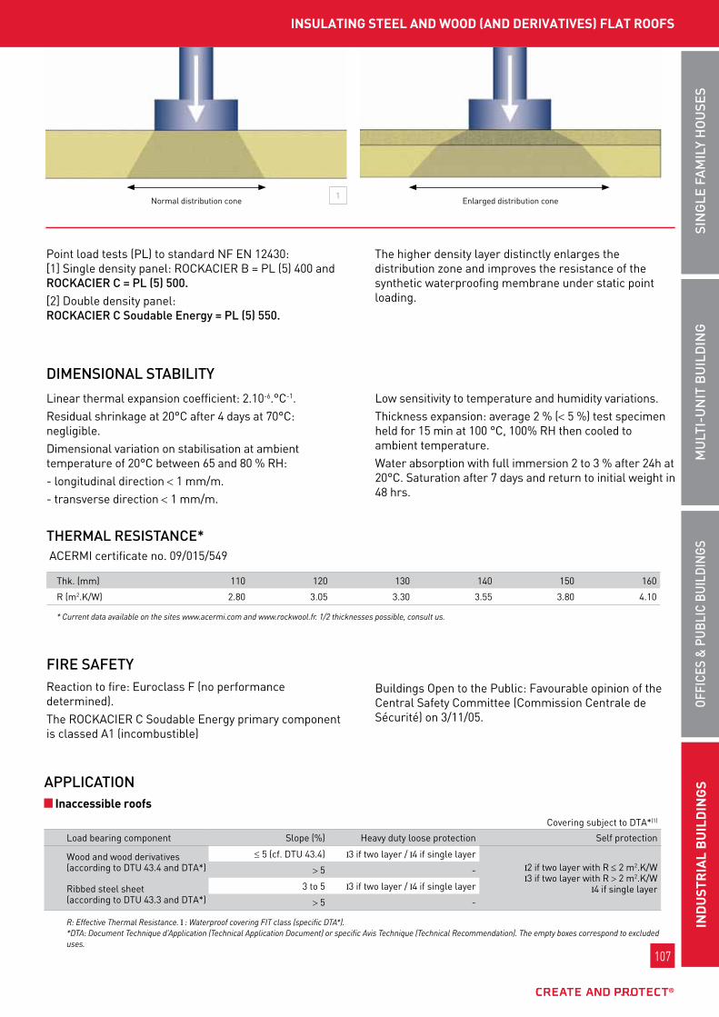
107
oFFI
CES
& P
uBL
IC B
uIL
DIn
gSM
uLt
I-u
nIt
Bu
ILD
Ing
SIn
gLE
FA
MIL
y H
ou
SES
InD
uSt
RIA
L B
uIL
DIn
gS
107
Ind
uSt
rIA
L b
uIL
dIn
gS
oFFI
CES
& P
uBL
IC B
uIL
DIn
gSM
uLt
I-u
nIt
Bu
ILD
Ing
SIn
gLE
FA
MIL
y H
ou
SES
DIMEnSIonAL StABILIty
InSuLAtIng StEEL And wood (And dErIVAtIVES) fLAt roofS
FIRE SAFEty Reaction to fire: Euroclass f (no performance determined). the RockAcIER c soudable Energy primary component is classed A1 (incombustible)
buildings open to the public: favourable opinion of the central safety committee (commission centrale de sécurité) on 3/11/05.
tHERMAL RESIStAnCE* AcERmI certificate no. 09/015/549
thk. (mm) 110 120 130 140 150 160
R (m2.k/w) 2.80 3.05 3.30 3.55 3.80 4.10
* Current data available on the sites www.acermi.com and www.rockwool.fr. 1/2 thicknesses possible, consult us.
1normal distribution cone Enlarged distribution cone
point load tests (pl) to standard nf En 12430: [1] single density panel: RockAcIER b = pl (5) 400 and RoCkACIER C = PL (5) 500. [2] Double density panel: RoCkACIER C Soudable Energy = PL (5) 550.
the higher density layer distinctly enlarges the distribution zone and improves the resistance of the synthetic waterproofing membrane under static point loading.
linear thermal expansion coefficient: 2.10-6.°c-1. Residual shrinkage at 20°c after 4 days at 70°c: negligible. Dimensional variation on stabilisation at ambient temperature of 20°c between 65 and 80 % RH:- longitudinal direction < 1 mm/m.- transverse direction < 1 mm/m.
low sensitivity to temperature and humidity variations. thickness expansion: average 2 % (< 5 %) test specimen held for 15 min at 100 °c, 100% RH then cooled to ambient temperature. water absorption with full immersion 2 to 3 % after 24h at 20°c. saturation after 7 days and return to initial weight in 48 hrs.
covering subject to DtA*(1)
load bearing component slope (%) Heavy duty loose protection self protection
wood and wood derivatives(according to Dtu 43.4 and DtA*)
≤ 5 (cf. Dtu 43.4) 3 if two layer / 4 if single layer2 if two layer with R ≤ 2 m2.k/w3 if two layer with R > 2 m2.k/w
4 if single layer
> 5 -
Ribbed steel sheet (according to Dtu 43.3 and DtA*)
3 to 5 3 if two layer / 4 if single layer
> 5 -
R: Effective Thermal Resistance. : Waterproof covering FIT class (specific DTA*). *DTA: Document Technique d’Application (Technical Application Document) or specific Avis Technique (Technical Recommendation). The empty boxes correspond to excluded uses.
APPLICAtIon Inaccessible roofs

108
www.rockwool.fr
108
www.rockwool.fr
roCkACIEr C SoudAbLE EnErgy
*DTA: Document Technique d’Application (Technical Application Document) or specific Avis Technique (Technical Recommendation)
covering subject to DtA*
load bearing component slope (%) Heavy duty loose protection self protection
wood and wood derivatives(according to Dtu 43.4 and DtA*)
≤ 5 (cf. Dtu 43.4) 4
45 to 50 -
Ribbed steel sheet (according to Dtu 43.3 and DtA*)
3 to 5 4
5 to 50 -
covering subject to DtA*
load bearing component slope (%) Heavy duty loose protection self protection
wood and wood derivatives(according to Dtu 43.4 and DtA*)
≤ 5 (cf. Dtu 43.4) 4
45 to 7 -
Ribbed steel sheet (according to Dtu 43.3 and DtA*) 3 to 5 4
Root resistant coverings for garden flat roof subject to DtA*
load bearing component slope (%) separate covering (1) self protection
Ribbed steel sheeting (cf. Dtu 43.3) 3 to 20 fIt class " 5" fIt class " 5"
: Waterproof covering FIT class (specific DTA* and Technical Recommendations). FIT class: " ": Puncture resistance (NF P 84 - 352) of waterproof covering (specific Technical Recommendations). (1) With dry substrate weight > 66 kg/m2. (2) With dry substrate weight > 66 kg/m2. (3) In accordance with the CSFE TTV (Green roof) professional rules. The empty boxes correspond to excluded zones.
Reminder: all our DtAs* state that, to avoid damage due to frequent passage during work, the panels must be covered with a rigid protection, for example a wooden decking.
walkways
Extensive or semi-extensive green flat roofs
Equipment zones
the panels must be laid in a chequer board pattern, covered face upwards (see Dtu 43.3 and 43.4). the continuous line of joints between panels must be perpendicular to the ribs of the steel sheeting (see Dtu 43.3). when laid in several layers, use RockAcIER c nu first (fixing according to Dtu 43.3). the final layer that must receive the waterproofing must be RockAcIER c soudable Energy (fixing according to DtA*). laying in several layers: the joints of successive layers must not be superimposed. on load bearing components made from wood or wood derivative panels: see Dtu 43.4.
non-traditional coverings are applied by welding only according to the methods defined in their respective DtAs*. traditional coverings are those described in Dtu series 43, according to the above slopes and conditions of use. the use of EAC (Hot Applied Coating) bitumen directly on RoCkACIER C Soudable Energy is prohibited.
ARRAngEMEnt WAtERPRooFIng

109
oFFI
CES
& P
uBL
IC B
uIL
DIn
gSM
uLt
I-u
nIt
Bu
ILD
Ing
SIn
gLE
FA
MIL
y H
ou
SES
InD
uSt
RIA
L B
uIL
DIn
gS
109
Ind
uSt
rIA
L b
uIL
dIn
gS
oFFI
CES
& P
uBL
IC B
uIL
DIn
gSM
uLt
I-u
nIt
Bu
ILD
Ing
SIn
gLE
FA
MIL
y H
ou
SES
InSuLAtIng StEEL And wood (And dErIVAtIVES) fLAt roofS
"step-resistant" fastening assemblies (connectors and plate) must be used in accordance with the provisions of cstb booklet no. 3564 and the DtA*. In particular "EtAncoplAst Hp" thermal break fixings from EtAnco [1] [2] and [3] could be used.fixing placed about 20 cm from the edge of the panel.
the Specification determines the minimum densities of fixings to be used according to different parameters.
Applications in accordance with the Dtu and DtA* the limits on use of Rockacier c soudable Energy are those defined in Dtu 43.3, 43.4 and its specific technical Application Document (DtA).
FIXIngS LIMItAtIonS on uSE
1 2 3
Insulation
no
Insulation
yES
*DTA: Technical Application Document (Document Technique d’Application) or specific Technical Recommendation (Avis Technique)
* current DTA available on the site www.cstb.fr. Refer to our Internet site to find the latest update of the datasheet.
reference documents Decree no. 2006-592 of 24 may 2006 on building thermal characteristics and energy performance - J.o. (official Journal) of 25 may 2006. order of 24 may 2006 on the thermal characteristics of new buildings and new parts of buildings - J.o. of 25 may 2006. Decree no. 2007-363 of 19 march 2007 on feasibility studies of energy supplies, thermal specifications and energy performance of existing buildings and posting of the energy performance diagnostic report - J.o. (official Journal) of 21 march 2007. order of 3 may 2007 on thermal characteristics and energy performance of existing buildings. - J.o. of 17 may 2007. order of 22 february 2002, bringing into application for thermal insulation products manufactured for buildings decree no. 92-647 of 8 July 1992. Directive 89/106/cEE of the council of 21 December 1988 on the approximation of legislative, regulatory and administrative provisions of member states concerning construction products. standard nf En 13162, thermal insulation products for building, products manufactured from mineral wool. Dtu 43.3 and 43.4. uEAtc technical guide. DtA*: request in progress – under specifications from socotEc.
Insuranceten-year civil Responsibility insurance policy for building material manufacturers, importers and equivalents, covering Rockwool france s.A.s in application of the provisions of the law of January 4, 1978 and Article 1792-4 of the french civil code, to the exclusion of all installers’ guarantees.
No reference to the name and brand of this product can be made in technical recommendations or technical documents without the written agreement of ROCKWOOL France.
*DTA: Document Technique d’Application (Technical Application Document) or specific Avis Technique (Technical Recommendation)
n.B. : the DtA* for RockAcIER c soudable Energy does not address load bearing components made from ribbed steel sheeting with a profile top opening of > 70 mm. please refer to the Rockvallée technical datasheet for this application.

110
www.rockwool.fr
110
www.rockwool.fr
roCkACIEr b nu
ADVAntAgES
DIMEnSIonS
roCkACIEr b nu
RockAcIER b nu is a non load bearing insulation panel forming a direct support for bituminous waterproof coverings on flat and inclined roofs of inaccessible flat roofs*, including walkways.these flat roofs are composed of load bearing elements made from ribbed steel sheeting, in wood and derivatives, for slopes compliant with Dtu 43.3 and 43.4.RockAcIER b nu is not intended to be applied on wide span steel decks, under vegetation, or under photovoltaic or synthetic membranes.
*Inaccessible roofs are roofs for which traffic is limited to their maintenance only.
FIELD oF APPLICAtIon
thermal and acoustic performance Excellent mechanical strength due to straightened fibres Reaction to fire: Euroclass A1 (incombustible) more efficient installation due to the long length format Dimensional stability Rot proof
Available in 2 dimensions: - standard: l. 1200 x l. 1000 mm - gl : l. 2400 x w. 600 mm
from 80 mm thickness Identification of compressibility classes:
- class b = blue label colour and presence of marking on the panel edge
MECHAnICAL CHARACtERIStICS
weight characteristics values
thickness (mm) 40 to 45 50 to 80 85 to 180
stone wool density (kg/m3) 157 (average)
135 (average)
125 (average)
compressibility class (uEAtc)
class b / deformation ≤ 5% under test load of 20 kpa
tension perpendicular to the faces 20 kpa average (nf En 1607)
compression stress at 10% ≥ 50 kpa ≥ 40 kpa
High-density bare stone wool insulating panel. the orientation of the fibres is controlled during manufacture, providing enhanced mechanical performance.
tHERMAL RESIStAnCE*
thk. (mm) 40 45 50 55 60 65 70 75 80 85
R (m2.k/w) 1.00 1.15 1.25 1.40 1.50 1.65 1.75 1.90 2.05 2.15
thk. (mm) 90 95 100 105 110 115 120 125 130 135
R (m2.k/w) 2.30 2.40 2.55 2.65 2.80 2.95 3.05 3.20 3.30 3.45
thk. (mm) 140 145 150 155 160 165 170 175 180
R (m2.k/w) 3.55 3.70 3.85 3.95 4.10 4.20 4.35 4.45 4.60
Minimum quantity: refer to the current price list.The black box shows the safe value corresponding to the regulatory minimum set by RT 2005 (in accordance with Th-U rules including included thermal bridges for four 4.8 mm- diameter fastenings per m2).
CERtIFICAtES
ACERMI kEyMARk 04/015/295 008-sDg5-295
DoP cpR- Dop-fR-038

111
oFFI
CES
& P
uBL
IC B
uIL
DIn
gSM
uLt
I-u
nIt
Bu
ILD
Ing
SIn
gLE
FA
MIL
y H
ou
SES
InD
uSt
RIA
L B
uIL
DIn
gS
111
Ind
uSt
rIA
L b
uIL
dIn
gS
oFFI
CES
& P
uBL
IC B
uIL
DIn
gSM
uLt
I-u
nIt
Bu
ILD
Ing
SIn
gLE
FA
MIL
y H
ou
SES
InSuLAtIng StEEL fLAt roofS
linear thermal expansion coefficient: 2 x 10⁻⁶.°c-1.Residual shrinkage at 20 °c after 4 days at 70 °c: negligible.Dimensional variation on stabilisation at ambient temperature of 20 °c between 65 and 80 % RH: - longitudinal direction< 1 mm per m; - transverse direction < 1 mm per m.low sensitivity to temperature and humidity variations.Average thickness expansion 2% (< 5%) (test specimen maintained at 100°c for 15 min., 100% RH then cooled back to ambient temperature).water absorption with full immersion 11 to 12% at 20 °c after 7 days and saturation. Return to initial weight in 48 hrs.
DIMEnSIonAL StABILIty
APPLICAtIon Inaccessible roofs
walkways
ACouStIC PERFoRMAnCE
A Test no. 06/CTBA–IBC/PHY/60/1b Test no. 06/CTBA–IBC/PHY/60/2
productsRw (c;ctr) in db
RA RA,tr
A tAn 75/100th + RockAcIER b nu 80 mm + waterproofing
37 (-2; -7)
35 30
b tAn 125/100th + RockAcIER b nu 120 mm + waterproofing
40 (-2; -7)
38 33
loose protection self protection
load bearing component slope (%) covering subject to DtA visible EAc (Hot Applied coating) bonded covering subject to DtA*
covering subject to DtA*mechanically fixed (3)
wood and wood derivatives (to nf Dtu 43.4 and DtA*)
(1) and ≤ 5fIt class:
3 if two layer4 if single layer fIt class:
2 if two layer withRth ≤ 2 m2.k/w
3 if two layer withRth > 2 m2.k/w4 if single layer
l3and according to DtA*
for the covering
> 5 -
Ribbed steel sheets(according to nf Dtu 43.3 and DtA*)
(2) and ≤ 5fIt class:
3 if two layer 4 if single layer
> 5 -
Rth: Thermal resistance. *DTA: Document Technique d’Application (Technical Application Document) or specific Avis Technique (Technical Recommendation).
The empty boxes correspond to excluded uses.
loose protection self protection
load bearing component slope (%) covering subject to DtA visible EAc (Hot Applied coating) bonded covering subject to DtA*
covering subject to DtA*mechanically fixed (3)
wood and wood derivatives (to nf Dtu 43.4 and DtA*)
(1) and ≤ 5 fIt class: 4
fIt class: 4l3
and according to DtA*for the covering
> 5 -Ribbed steel sheets(according to nf Dtu 43.3 and DtA*)
(2) and ≤ 5 fIt class: 4
> 5 -
(1) Minimum slope in accordance with standards NF PDTU 43.4 in new work and NF P 84-208 (DTU 43.5) in renovation(2) Minimum slope in accordance with standards NF PDTU 43.3 in new work and NF P 84-208 (DTU 43.5) in renovation(3) Step Resistant fixingsThe empty boxes correspond to excluded uses.

112
www.rockwool.fr
112
www.rockwool.fr
ARRAngEMEntthe panels must be laid in a chequer board pattern (see Dtu 43.3 and 43.4). the continuous line of joints between panels must be perpendicular to the ribs of the steel sheeting (see Dtu 43.3).on components made from ribbed steel sheeting: under mechanically-fastened covering:
- on flat slopes, each RockAcIER b nu panel receives a central fixing** beforehand (the final fixings are those defined in the covering DtA*);
- on curved slopes, 4 prior fastenings are used per panel. the arrangements for using the panels are those defined in Dtu 43.3: l ≤ √R/50 (R = radius of curvature).
coating backing separate or EAc (Hot Applied coating) bonded: comply with the provisions of Dtu 43.3.on load bearing elements made from wood or wood derivative panels: see Dtu 43.4.Installation in several layers: the joints of successive layers must not be superimposed.
reminder: all our DtAs* state that, to avoid damage due to frequent passage during work, the panels must be covered with a rigid protection, for example a wooden decking.
WAtERPRooFIngnon-traditional coverings are applied according to the methods defined in their respective DtAs*.traditional coverings are those described in Dtu series 43, according to the slopes and conditions of use in the standard.
FIXIngS"step-resistant" fastening assemblies (connectors and plates) must be used in accordance with the provisions of cstb booklet no. 3563 and the DtA*.
notes:- the edges are defined as equal to 1/10th of the building
height, and at least 2 m.- the corners result from the intersection of two edges
(or at least 4 m2).
LIMItAtIonS on uSEApplications in accordance with the dtu and dtA *the limits on use of RockAcIER b nu are those defined in Dtu 43.3, 43.4 and its specific technical Application Document.
n.b. : the DtA* for RockAcIER c nu does not address load bearing components made from ribbed steel sheeting with a profile top opening > 70 mm. please refer to the RockvAllÉE technical datasheet for this application.
roCkACIEr b nu
*DTA: Document Technique d’Application (Technical Application Document) or specific Avis Technique (Technical Recommendation)** Refer to the DTA for ROCKACIER B Nu

113
oFFI
CES
& P
uBL
IC B
uIL
DIn
gSM
uLt
I-u
nIt
Bu
ILD
Ing
SIn
gLE
FA
MIL
y H
ou
SES
InD
uSt
RIA
L B
uIL
DIn
gS
113
Ind
uSt
rIA
L b
uIL
dIn
gS
oFFI
CES
& P
uBL
IC B
uIL
DIn
gSM
uLt
I-u
nIt
Bu
ILD
Ing
SIn
gLE
FA
MIL
y H
ou
SES
InSuLAtIng StEEL fLAt roofS
reference documentsDecree no. 2006-592 of 24 may 2006 on building thermal characteristics and energy performance - J.o. (official Journal) of 25 may 2006.order of 24 may 2006 on the thermal characteristics of new buildings and new parts of buildings - J.o. of 25 may 2006.Decree no. 2007-363 of 19 march 2007 on feasibility studies of energy supplies, thermal specifications and energy performance of existing buildings and posting of the energy performance diagnostic report - J.o. (official Journal) of 21 march 2007. order of 3 may 2007 on thermal characteristics and energy performance of existing buildings. - J.o. of 17 may 2007.order of 22 february 2002, bringing into application for thermal insulation products manufactured for buildings decree no. 92-647 of 8 July 1992.Directive 89/106/cEE of the council of 21 December 1988 on the approximation of legislative, regulatory and administrative provisions of member states concerning construction products.standard nf En 13162, thermal insulation products for building, products manufactured from mineral wool.DtA* cstb no. 5/09-2047.Dtu 43.3 and 43.4.uEAtc technical guide.
InSurAnCEten-year civil Responsibility insurance policy for building material manufacturers, importers and equivalents, covering Rockwool france s.A.s. in application of the provisions of the law of January 4, 1978 and Article 1792-4 of the french civil code, to the exclusion of all installers’ guarantees.no reference to the name and brand of this product can be made in technical recommendations or technical documents without the written agreement of Rockwool france

114
www.rockwool.fr
114
www.rockwool.fr
roCkbArdAgE
stone wool panel, bare or covered with a black mineral sheath, with a density of 50 kg/m3, machined to integrate into the specific geometries of cladding plates.
ADVAntAgES
roCkbArdAgE
Reaction to fire Euroclass A1 (incombustible) for RockbARDAgE nu and revêtu.
Fire resistanceEI 30 min fire stop and Ew 120 min flame stop (EfEctIs no. 05-g-186 tests; cf. fitting description) for RockbARDAgE nu
Attenuation
Absorption
FIRE SAFEty
thickness (mm) 110 130 140
R (m2.k/w) 3.20 3.80 4.05
Quick and easy to apply single layer system complying with thermal regulations very significant reduction in thermal bridges fire safety:
Euroclass A1 (incombustible) - EI 30 min fire stop and Ew 120 min flame stop
the flatness of the facade gives an aesthetic rendering to the cladding due to the rigidity of the product Rot proof
RockbARDAgE
for straight lip plate
1 face with black film in the RockbARDAgE Revêtu case
RockbARDAgE
for box lip plate
10 mm groove Rebate
1 1
RockbARDAgE is intended for the thermo-acoustic insulation and passive fire protection of buildings with double-skin metallic cladding (vertical or horizontal). the black sheath on RockbARDAgERevêtu does not act as a vapour barrier.
FIELD oF APPLICAtIon
ACouStIC PERFoRMAnCE
test of standard 12.5 mm plaster board inner partition on 200 mm hollow block wall + 15 mm coating.
systemsRw (c;ctr) in db
RA RA,tr
A vertical double skin cladding comprising: plain plate 500 x 90 0.75 mm + RockbARDAgE nu thk. 130 mm + cladding profile 0.75 mm
46 (-5; -13)
41 33
b Horizontal double skin cladding comprising: plain plate 500 x 90 0.75 mm + RockbARDAgE nu thk. 130 mm + omega profile 15/10th 20 mm + cladding profile 0.75 mm
48 (-8; -17)
40 31
systems aw
perforated plate 500 x 90 0.75 mm+ RockbARDAgE Revêtu thk. 130 mm 0.95
A Test no. 05/CTBA–IBC/PHY/3198/1b Test no. 05/CTBA–IBC/PhY/170/1
Test no. 05/CTBA–IBC/PHY/3198/3
tHERMAL PERFoRMAnCE*
AcERmI certificates for RockbARDAgE nu no. 04/015/305 and Revêtu no. 08/015/477, on the main part of the panel
CERtIFICAtES
ACERMI kEyMARk 04/015/305 008-sDg5-305
DoP cpR- Dop-fR-043

115
oFFI
CES
& P
uBL
IC B
uIL
DIn
gSM
uLt
I-u
nIt
Bu
ILD
Ing
SIn
gLE
FA
MIL
y H
ou
SES
InD
uSt
RIA
L B
uIL
DIn
gS
115
Ind
uSt
rIA
L b
uIL
dIn
gS
oFFI
CES
& P
uBL
IC B
uIL
DIn
gSM
uLt
I-u
nIt
Bu
ILD
Ing
SIn
gLE
FA
MIL
y H
ou
SES
ExtErnAL InSuLAtIon of VErtICAL wALLS / doubLE MEtAL SkIn CLAddIng
APPLICAtIonfirst, the plate lips must be seamed every metre, halfway up the core.seaming the plates together is done using fAstovIs fcR2 4.8 x 17 mm (lR EtAnco) type screws or equivalent.
InStALLAtIon ASSIStAnCE PRoFILEfor ease of installation (fitting the water discharge flashing), it is recommended to make a profile at the bottom of the cladding, whose form should match the construction constraints (sole plate related constraints).Rockwool can supply examples of solutions. In this case, consult our technical department.
CHooSIng tHE InSuLAtIonthe reference of the insulation to be used is determined according to the depth and geometry of the plate. the compatibility of the RockbARDAgE reference with the plate geometry should be checked (straight or box lips).
InStALLIng tHE InSuLAtIon Straight lip cladding plate
Insert the panel into the top of the plate, then press the bottom of the panel to insert it.
box lip cladding plateInsert the panel by the bottom of the plate, then press the top of the panel to insert it under the lip.
plate depth (mm) RockbARDAgE thickness (mm)
70 110
90 130
100 140
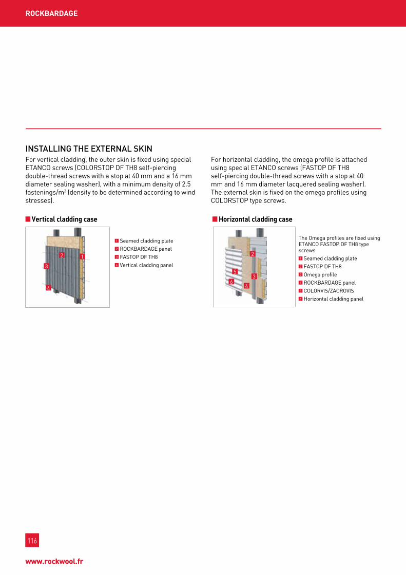
116
www.rockwool.fr
116
www.rockwool.fr
roCkbArdAgE
InStALLIng tHE EXtERnAL SkInfor vertical cladding, the outer skin is fixed using special EtAnco screws (coloRstop Df tH8 self-piercing double-thread screws with a stop at 40 mm and a 16 mm diameter sealing washer), with a minimum density of 2.5 fastenings/m2 (density to be determined according to wind stresses).
for horizontal cladding, the omega profile is attached using special EtAnco screws (fAstop Df tH8 self-piercing double-thread screws with a stop at 40 mm and 16 mm diameter lacquered sealing washer). the external skin is fixed on the omega profiles using coloRstop type screws.
Vertical cladding case Horizontal cladding case
1 seamed cladding plate2 RockbARDAgE panel 3 fAstop Df tH8 4 vertical cladding panel
12
4
3
the omega profiles are fixed using EtAnco fAstop Df tH8 type screws1 seamed cladding plate2 fAstop Df tH8 3 omega profile 4 RockbARDAgE panel 5 coloRvIs/ZAcRovIs 6 Horizontal cladding panel
1
2
4
5
63
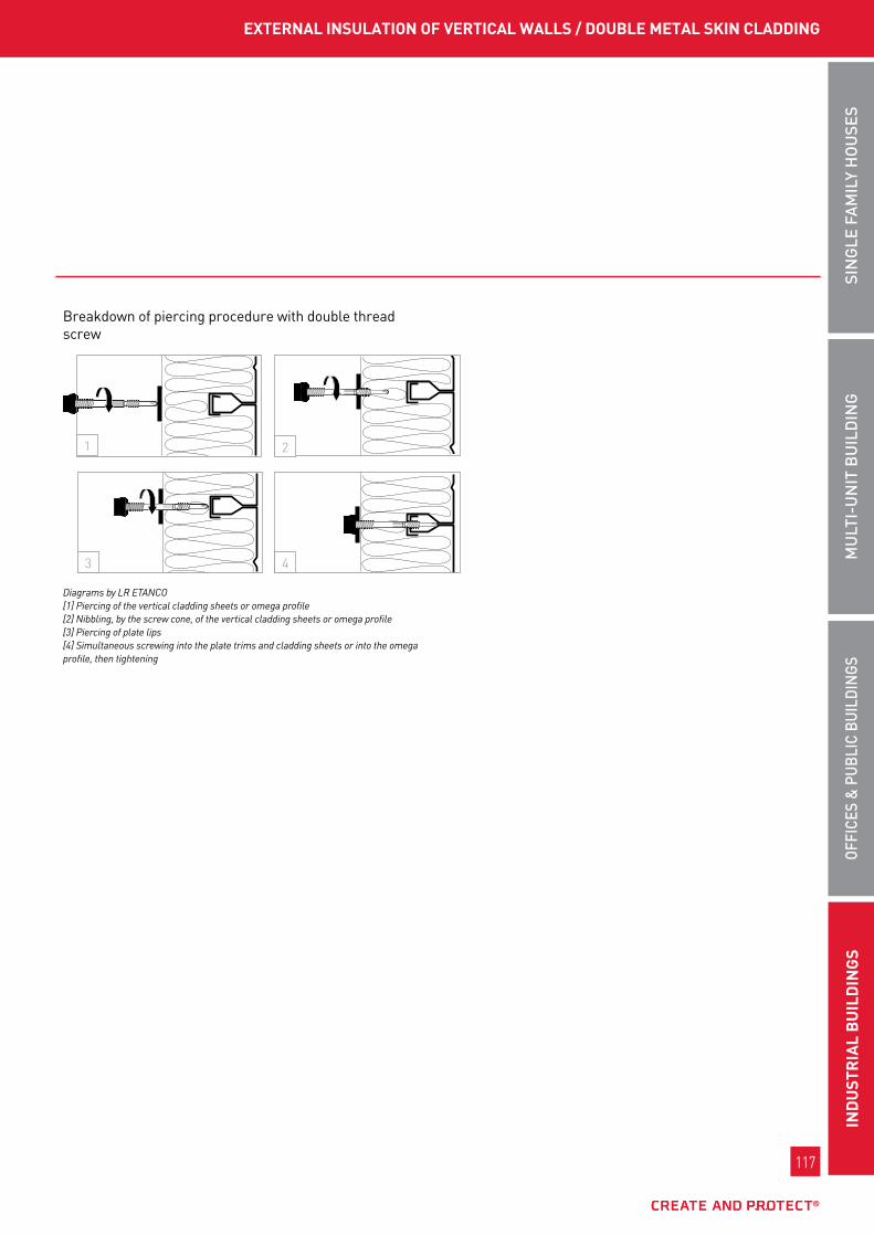
117
oFFI
CES
& P
uBL
IC B
uIL
DIn
gSM
uLt
I-u
nIt
Bu
ILD
Ing
SIn
gLE
FA
MIL
y H
ou
SES
InD
uSt
RIA
L B
uIL
DIn
gS
117
Ind
uSt
rIA
L b
uIL
dIn
gS
oFFI
CES
& P
uBL
IC B
uIL
DIn
gSM
uLt
I-u
nIt
Bu
ILD
Ing
SIn
gLE
FA
MIL
y H
ou
SES
breakdown of piercing procedure with double thread screw
Diagrams by LR ETANCO[1] Piercing of the vertical cladding sheets or omega profile[2] Nibbling, by the screw cone, of the vertical cladding sheets or omega profile[3] Piercing of plate lips[4] Simultaneous screwing into the plate trims and cladding sheets or into the omega profile, then tightening
1
3 4
2
ExtErnAL InSuLAtIon of VErtICAL wALLS / doubLE MEtAL SkIn CLAddIng

118
www.rockwool.fr
118
www.rockwool.fr
roCkStyL’ SyStEM
ADVAntAgES
roCkStyL’ SyStEM
fire resistance: Euroclass A1 (incombustible) EI 30* (provided by RockbARDAgE) limited available combustible mass < 50 mJ/m2* Easy maintenance complete system under technical
Recommendation
Rockstyl’ system is a non-traditional “double skin” cladding system, composed as follows: cladding plates, RockbARDAgE insulation system, rain barrier (metal or synthetic),
Reaction to fire RockbARDAgE nu and Revêtu, RockbARDAgE nu and Revêtu panels, of Euroclass A1, do not contribute to the development of fire on a façade.
Fire resistanceIn accordance with report EfEctIs 10 - A - 617, the use of RockbARDAgE nu and RockbARDAgE nu Energy panels, with thicknesses 130 and 150 mm used in cladding plates covered by the present report and extension in accordance with all the installation recommendations, allows an EI 30 minute fire stop and Ew 120 minute flame stop rating.
Insulation and trim for double skin cladding. Associated certificates technical Recommendation can be viewed on the site www.cstb.fr
the acoustic performance of this type of façade will depend on the choices of: - insulation thickness, - thickness of the internal metal plate - perforation ratio - external skin type,solutions including RockbARDAgE Energy could be the subject of case by case tests or simulations to justify their higher performance levels than classic solutions.
FIRE SAFEty
FIELD oF APPLICAtIon
ACouStIC PERFoRMAnCE
* With a metal rain barrier only.
1 cladding plate.
2 Insulation RockbARDAgE: stone wool with density 50 kg/m3.
3 synthetic or metal rain barrier.
4 metal secondary frame.
5 External facing RockpAnEl: compressed stone wool, density 1,050 kg/m3.
125 4 3

119
oFFI
CES
& P
uBL
IC B
uIL
DIn
gSM
uLt
I-u
nIt
Bu
ILD
Ing
SIn
gLE
FA
MIL
y H
ou
SES
InD
uSt
RIA
L B
uIL
DIn
gS
119
Ind
uSt
rIA
L b
uIL
dIn
gS
oFFI
CES
& P
uBL
IC B
uIL
DIn
gSM
uLt
I-u
nIt
Bu
ILD
Ing
SIn
gLE
FA
MIL
y H
ou
SES
InSuLAtIng doubLE SkIn MEtAL CLAddIng
APPLICAtIonthe Rockwool company does not undertake installation but is able to provide technical advice on the most suitable Rockwool products and their installation methods.
prior arrangements for the load bearing structurethe load bearing structure, including the headers, and the metal inserts in concrete components, etc. must comply with the requirements of the "professional Rules for the manufacture and Application of metal cladding" (“Règles professionnelles pour la fabrication et la mise en oeuvre des bardages métalliques”), 2nd edition, January 1981, notably in terms of nature, dimensions and tolerances.A header must be provided around openings for a dimension greater than 400 mm, but also for an opening necessitating cutting the flanges of a plate. If appropriate the load bearing frame must meet fire resistance requirements consistent with those required for the complete wall.
for cladding with an intermediate frame, the sole plate must be designed to be used as the bottom support for the vertical uprights. failing this the special contract documents must define the substitute arrangements adopted.
Installing cladding platesthe application of the plates shall comply with the requirements of the "professional Rules for the manufacture and Application of metal cladding"(“Règles professionnelles pour la fabrication et la mise en oeuvre des bardages métalliques”), 2nd edition, January 1981.the plates shall be seamed together as installation progresses, at half support height of the plate flange, complying with a 1 m spacing. the overhang of the plates (protrusion of the plates beyond the plane of the support) shall be limited to 0.30 m.In this specific case, a seam fixing shall be arranged at the end of the plate overhang, at about 50 mm from the edge.
Attenuation
Absorption
systems RA (db)Rw
(db) RA,tr (db) Ref. no.
plate 500 x 92 thk. 0.75 mm (8.6 kg/m2)+ RockbARDAgE Energy insulation 150 mm+ synthetic rain barrier+ RockpAnEl cladding® 8 mm (8.8 kg/m2)
47 51 (-4 ; - 11) 40 404-10-293-4
plate 500 x 92 thk. 0.75 mm (8.6 kg/m2)+ RockbARDAgE Energy insulation 150 mm+ metal rain barrier profile 0.75 mm (6.1 kg/m2)+ RockpAnEl cladding® 8 mm (8.8 kg/m2)
47 49 (- 2 ; - 9) 40 404-10-293-5
perforated plate 15 % 500 x 92 thk. 0.75 mm (7.5 kg/m2)+ RocksouRDInE vapour barrier + RockbARDAgE nu Energy 150 mm+ Rain barrier 0.75 mm (6.1 kg/m2)+ RockpAnEl cladding® 8 mm (8.8 kg/m2)
39 42 (-3; -9) 33 404-10-293-6
systems aw
perforated plate 15 % 500 x 92 thk. 0.75 mm (7.5 kg/m3)+ RocksouRDInE vapour barrier+ RockbARDAgE nu Energy
0.85 l
Test no. 404-08-47-5 - Other tests are available on the ROCKWOOL Extranet.

120
www.rockwool.fr
120
www.rockwool.fr
Insulation fixing1 Straight lip cladding plate
Insert the panel into the top of the plate, position it in contact with the previous one, then press the bottom of the panel for final insertion.
2 Box lip cladding plateInsert the panel into the bottom of the plate, position it in contact with the previous one, then press the top of the panel to insert it under the top lip. It does not matter whether the rebate is at the top or bottom.RockbARDAgE panels are always inserted inside the cladding panels with good joints between them and preferably with staggered joints.In no case can the grooved version of RockbARDAgE panels be used for box lip plates. the rebated version is intended for use with box lip plates. However, in exceptional cases, it can be used for straight lip plates, subject to the two conditions of taking the thermal performance obtained with the box lip plates and any dispersion due to the different plate geometries into account.the insulating panels shall have staggered joints between two consecutive plates. panels can overhang, in particular to create thermal breaks at the features (example: external corner).the maximum overhang shall be 200 mm, the insulation panel must fit at least 500 mm into the panel.for average humidity premises and perforated or pierced plates, the RocksouRDInE vapour barrier is applied at the bottom of the plates and made watertight around the edge by a cobAnD adhesive strip.
fitting the rain barrier1 Metal rain barrier
(the building height is limited to 20 metres with this type of rain barrier)the recommendations for application of the external skin of ribbed plate metal cladding are essentially defined by the "professional Rules for manufacture and Application of metal cladding" (“les Règles professionnelles pour la fabrication et la mise en oeuvre des bardages
métalliques”) 2nd edition of January 1981, particularly for installation with vertical ribs and with regard to the following points: - installation direction,- overlaps,- minimum density and distribution of fixings,- seaming,- specific feature of the filéa profile: due to its low rib
height, the longitudinal overlap must be a minimum of two ribs.
the fixings for a metal rain barrier directly supported on the insulation must always be double threaded self-piercing type with sealing washer (EtAnco brand fAstop coloRstop 2.5Df/2c Ø 5.5 or sfs brand sDRt2-l12-A16-5.5 type) and length suiting the thickness of the thermal break (70 mm screw for a 40 mm break, 90 mm screw for a 60 mm break).fixing of ribbed plates is done:- At the end of the plates, whether or not overlapping: one
fixing per main longitudinally overlapping rib, and one fixing for the other main ribs (or 1/2 if the ribs are very close). for plates with more than 5 ribs per metre, a limit of 5 fixings per metre is applied.
- on the vertical edge of the cladding: one fixing per plate. by analogy, the edge rib parallel to a corner or an opening is to be fixed on each plate lip.
- A recommended maximum spacing of 1.60 m between two successive fixings located on the same vertical axis. the maximum spacing between two horizontal lines of fixings is equal to one plate width.
- A minimum fixing density of 2.5 fixings per m2 of cladding with appropriate reinforcing in building corners. the fixing density shall be defined according to the climatic constraints taking into consideration an assembly strength of 33.0 dan per fixing under normal wind, without in any case having fewer than 2.5 fixings m2. when the metal rain barrier has an area density greater than 8 kg/m2, the fixing density should be adapted according to the following rule: 3.2 kg/m2/fixing. During fitting of the metal rain barrier this must be temporarily held for the time necessary to install the final fixings.
roCkStyL’ SyStEM
121
oFFI
CES
& P
uBL
IC B
uIL
DIn
gSM
uLt
I-u
nIt
Bu
ILD
Ing
SIn
gLE
FA
MIL
y H
ou
SES
InD
uSt
RIA
L B
uIL
DIn
gS
121
Ind
uSt
rIA
L b
uIL
dIn
gS
oFFI
CES
& P
uBL
IC B
uIL
DIn
gSM
uLt
I-u
nIt
Bu
ILD
Ing
SIn
gLE
FA
MIL
y H
ou
SES
2 Synthetic rain barrierIntroduction: The synthetic rain barrier can only be used for blank façades and on a building of less than 9 metres. It is not intended for use on cladding with perforated, or pierced plates, or façades including bays.before applying the external facing on the main surface, the duration of exposure of DEltAfAssADE s plus, shall be limited to a maximum of 5 weeks direct exposure to weather and uv.
Application on the main part. the rain barrier is stretched vertically or horizontally directly in contact with the thermal insulation, with the smooth black face facing towards the outside.
Vertical installationthe rain barrier shall be turned back over a metal component, either on the upper return of the last plate at the top edge, or on the upper part of a metal tube, then fixed mechanical at the top edge of the cladding by pinching between the above mentioned support and a metal part, or approximate width 50 mm, applied at points, with 2 fixings per metre.Holding the rain barrier at the top shall be completed by regular fixing in the main part directly into the insulation using DEltA ®- QuIckfIxx synthetic screws (fixing density: about 1 screw/m2). the successive vertical strips shall be assembled together using the self adhesive edges included in the DEltA®-fAssADE s plus rain barrier, the overlap width shall be a minimum of 10 cm. take care to align the strips vertically.
Horizontal installationthe first rain barrier strip shall be laid on the bottom edge. succeeding strips are applied with a bonded overlap in the water run off direction.temporary fixing of the rain barrier into the insulation shall be done using DEltA®-QuIckfIxx synthetic screws applied in 2 parallel rows:- the first at the top part of the strip above the self-adhesive
edge (in the top 20 mm of the strip),- the second at mid-height.the first bottom strip shall be fixed with 3 parallel rows of DEltA®-QuIckfIxx, with about one screw per metre.
waterproofing of the DEltA®-QuIckfIxx synthetic screws is done by bonding with DEltA®-tApE fAs adhesive tape (pieces with dimensions about 60 x 60 mm).At the bottom edge the flexible synthetic rain barrier shall overlap the water discharge flashing and shall be bonded using DEltA®-tHAn cartridge glue.final retention of the rain barrier shall be provided by the secondary frame (vertical metal sections), with 600 mm maximum spacing, mechanically fixed into the plate lips with fAstop spacer screws from EtAnco or sDRt2-l12-A16-5.5 from sfs.
fixing the secondary framethe implementation of the intermediate frame must comply with cstb booklet no. 3194. the secondary frame is a flanged design.the uprights are fixed onto each lip of the plate by fAstop coloRstop or sDRt2-l12-A16-5.5 fixings.the uprights butt together with a gap of about 5 mm.for a metal rain barrier, in line with each fixing and continuing along, it is essential that there should be an EpDm adhesive strip between the rain barrier sheet and the frame.the distance between these fixings and the overhanging end of the secondary frame is: - minimum: 50 mm. - maximum: 300 mm.predrilling shall be done before fitting the fixing screws for the uprights. the predrilling varies according to the fixing used:- 4 - 4.5 mm for EtAnco screws (fAstop coloRstop),- 6.5 mm for sfs screws (sDRt2-l12-A16-5,5).the fixings for the frame, directly supported on the insulation, must always be double threaded self-piercing type with sealing washer of fAstop coloRstop 2.5.5Df/2c Ø 5.5 or sDRt2-l12-A16-5.5 type and length suiting the thickness of the thermal break (70 or 64 screw for a 40 mm break, 90 or 84 screw for a 60 mm break).the spacing of the upright fixings on the plate flanges must not exceed two metres on the same plate (or rib) flange, in the main part, or 1.5 m in zones with increased wind suction, (meaning vertical edges - 1/10th of the width of the building).
InSuLAtIng doubLE SkIn MEtAL CLAddIng
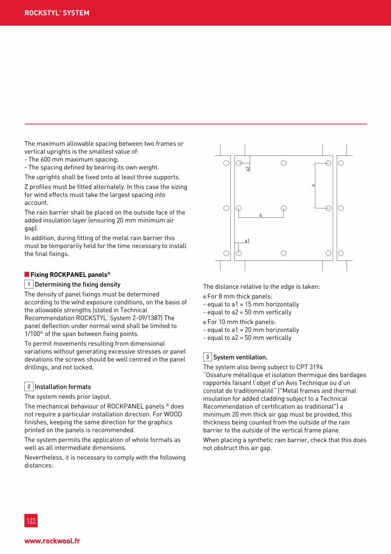
122
www.rockwool.fr
122
www.rockwool.fr
the maximum allowable spacing between two frames or vertical uprights is the smallest value of: - the 600 mm maximum spacing; - the spacing defined by bearing its own weight.the uprights shall be fixed onto at least three supports.Z profiles must be fitted alternately. In this case the sizing for wind effects must take the largest spacing into account.the rain barrier shall be placed on the outside face of the added insulation layer (ensuring 20 mm minimum air gap).In addition, during fitting of the metal rain barrier this must be temporarily held for the time necessary to install the final fixings.
fixing roCkpAnEL panels®
1 Determining the fixing densitythe density of panel fixings must be determined according to the wind exposure conditions, on the basis of the allowable strengths (stated in technical Recommendation Rockstyl’ system 2-09/1387) the panel deflection under normal wind shall be limited to 1/100th of the span between fixing points.to permit movements resulting from dimensional variations without generating excessive stresses or panel deviations the screws should be well centred in the panel drillings, and not locked.
2 Installation formatsthe system needs prior layout.the mechanical behaviour of RockpAnEl panels ® does not require a particular installation direction. for wooD finishes, keeping the same direction for the graphics printed on the panels is recommended.the system permits the application of whole formats as well as all intermediate dimensions.nevertheless, it is necessary to comply with the following distances:
a1a2
a
b
the distance relative to the edge is taken: for 8 mm thick panels:
- equal to a1 = 15 mm horizontally - equal to a2 = 50 mm vertically for 10 mm thick panels:
- equal to a1 = 20 mm horizontally - equal to a2 = 50 mm vertically
3 System ventilation.the system also being subject to cpt 3194 “ossature métallique et isolation thermique des bardages rapportés faisant l’objet d’un Avis technique ou d’un constat de traditionnalité” ("metal frames and thermal insulation for added cladding subject to a technical Recommendation of certification as traditional") a minimum 20 mm thick air gap must be provided, this thickness being counted from the outside of the rain barrier to the outside of the vertical frame plane.when placing a synthetic rain barrier, check that this does not obstruct this air gap.
roCkStyL’ SyStEM

123
oFFI
CES
& P
uBL
IC B
uIL
DIn
gSM
uLt
I-u
nIt
Bu
ILD
Ing
SIn
gLE
FA
MIL
y H
ou
SES
InD
uSt
RIA
L B
uIL
DIn
gS
123
Ind
uSt
rIA
L b
uIL
dIn
gS
oFFI
CES
& P
uBL
IC B
uIL
DIn
gSM
uLt
I-u
nIt
Bu
ILD
Ing
SIn
gLE
FA
MIL
y H
ou
SES
4 Expansion of RoCkPAnEL panels® Durable/Durable AgRockpAnEl ® Durable/Durable Ag panels have little sensitivity to dimensional variations (< 0.7 mm/m). the drilling of holes must take this dimensional variation of the structure into account. for panels in formats greater than 1,000 mm x 1,000 mm, “mobile points” should be drilled to the following diameters:A point is generally placed in the centre of the panel. It is called the “fixed point” and has a diameter equal to the diameter of the rivet body or screw. tightening fixings must be moderated by the use of a tightening block on the end of the riveter or a screwdriver with adjustable depth stop.
fixing type Diameter of mobile point
Rivets 8 mm
screws 8 mm
the panels are arranged so as to create vertical and horizontal joints of width proportional to the expansion. In practice the joint width is defined at a nominal value of 8 mm. Refer to the current RockpAnEl technical Recommendations ® at the cstb.
feature pointsfor design principles at features refer to the "professional Rules for the manufacture and Application of metal cladding" (“Règles professionnelles pour la fabrication et la mise en oeuvre des bardages métalliques”), 2nd edition, January 1981.
InSuLAtIng doubLE SkIn MEtAL CLAddIng
reference documents Application standards
- technical recommendation Rockstyl’ no. 2/12-1521 - Règles professionnelles pour la fabrication et la mise en œuvre des
bardages métalliques (Professional rules for the manufacture and application of metal cladding), 2nd edition January 1981
- cstb booklet no. 3194 product standard: nf En 13162: products manufactured in mineral wool (mw) orders and decrees
Building energy performance: - order of 24 may 2006 on the thermal characteristics of new buildings and
new parts of buildings.- Decree no. 2006-592 of 24 may 2006 on building thermal characteristics
and energy performance.- order of 15 september 2006 on energy performance diagnosis for
existing buildings offered for sale in metropolitan france.- order of 3 may 2007 on energy performance diagnosis for existing
buildings used mainly as dwellings and offered for rent in metropolitan france.
- order of 3 may 2007 on thermal characteristics and energy performance of existing buildings.
- order of 13 June 2008 on the energy performance of existing buildings with area greater than 1,000 square metres, when they are subject to major renovation works.
- order of 21 september 2007 on energy performance diagnosis for new buildings in metropolitan france. tax credit:
- order of 13 november 2007 made for the application of article 200 quater of the general tax code relating to main residence equipment expenditure and modifying article 18 bis of appendix Iv to this code. fire regulations:
- order of 6 october 2004 approving provisions of the completing and modifying the safety regulations against the risk of fire and panic in buildings open to the public.
- order of 4 July 2007 completing and modifying the safety regulations against the risk of fire and panic in buildings open to the public.
- section 1510: storage of combustible materials, products or substances in covered warehouses. Acoustic regulations:
- order of 30 June 1999 - nRA 2000 housing regulations- order of 25 April 2003 - Health care establishment regulations- order of 25 April 2003 - Educational establishment regulations- order of 25 April 2003 - Hotel regulations- order of 30 may 1996 - Regulations for external acoustic insulation- Decree of 31 August 2006 - Environmental noise regulations
InSurAnCEten-year civil Responsibility insurance policy for building material manufacturers, importers and equivalents, covering Rockwool france s.A.s. in application of the provisions of the law of January 4, 1978 and Article 1792-4 of the french civil code, to the exclusion of all installers’ guarantees.no reference to the name and brand of this product can be made in technical recommendations or technical documents without the written agreement of Rockwool france
* Current Technical Recommendations available on the site www.cstb.com.Refer to our Internet site to find the latest update of the datasheet.

124
www.rockwool.fr
124
www.rockwool.fr
ConLIt 150 u
ADVAntAgES
ConLIt 150 u
the fire resistance of pipe penetrations depends on various factors such as the type of pipe, its diameter, the basic structure, use of the pipe, etc. fire stop insulation requires special attention for the correct choice of materials and implementation.Ask for our detailed brochure “protection anti-feu des traversées de conduits” (fire stop protection of pipe penetrations).
SuMMARy oF InStALLAtIon InStRuCtIonS
well sized: the external diameter is equal to the diameters of 60, 80, 100, 130, 150, 180, 220, 250 and 280 mm holes Direct pipe fixing and centring Easily identifiable due to the clear printing on the aluminium foil for both metal and synthetic pipes for both solid and plasterboard structures simple to install optimum fire safety, combined with acoustic and thermal insulation tested and approved in accredited laboratories (fire reaction and resistance)
conlIt 150 u shells have been designed to construct fire stop pipe penetrations. these shells are applied to make both metal and inflammable pipe penetrations fire resistant, for both walls and floors. the external diameter of the shells suits the most commonly used hole diameters.to plug the openings it is possible to apply conlIt 150 u shells combined with the conlIt pEnEtRAtIon boARD panel for penetrations.
tECHnICAL CHARACtERIStICS
performance standards
coefficient of thermal conductivity λ10 = 0.040 (w/mk) En Iso 8497
Reaction to fire m0 nf p 92507
fire resistancefire resistance from 30 to 120 minutes
• Protection of varied types of metal pipes • Protection of varied types of plastic pipes
water absorption water absorption < 1 kg/m2 En 13472
Air thickness equivalent to the water vapour diffusion resistance sd ≥ 200 m En 13469

125
oFFI
CES
& P
uBL
IC B
uIL
DIn
gSM
uLt
I-u
nIt
Bu
ILD
Ing
SIn
gLE
FA
MIL
y H
ou
SES
InD
uSt
RIA
L B
uIL
DIn
gS
125
Ind
uSt
rIA
L b
uIL
dIn
gS
oFFI
CES
& P
uBL
IC B
uIL
DIn
gSM
uLt
I-u
nIt
Bu
ILD
Ing
SIn
gLE
FA
MIL
y H
ou
SES
fIrE Stop InSuLAtIon of pIpE pEnEtrAtIonS
PACkIng Quantity per box
shell length: 1000 mm package per box
ReferenceØ int.(mm)
thk.(mm)
[ ext.(mm)
ml / box
31987 10 25 60 42
31988 12 25 60 42
31989 14 23 60 42
31990 15 22.50 60 42
31991 16 22 60 42
31992 17 21.50 60 42
31960 18 21 60 42
31993 20 20 60 42
31961 21 19.50 60 42
31994 22 19 60 42
31995 25 17.50 60 42
31996 26 17 60 42
31962 27 16.50 60 42
31997 28 26 80 20
31998 32 24 80 20
31963 35 22.50 80 20
31999 40 20 80 20
31964 42 19 80 20
32000 42 29 100 14
31965 48 26 100 14
32001 50 25 100 14
32002 54 38 130 9
32003 58 36 130 9
31966 60 35 130 9
55022 63 33.50 130 9
55036 64 33 130 9
55327 64 58 180 4
55822 75 52.50 180 4
ReferenceØ int.(mm)
thk.(mm)
[ ext.(mm)
ml / box
26797 76 37 150 5
55037 76 52 180 4
53402 78 36 150 5
55023 83 33.50 150 5
26798 89 30.50 150 5
55824 89 65.50 220 2
56009 90 65 220 2
55834 102 39 180 4
27009 108 36 180 4
55786 108 71 250 1
55835 110 35 180 4
55788 110 70 250 1
55826 113 68.50 250 1
29109 114 33 180 4
55789 114 68 250 1
56050 133 43.50 220 2
55954 135 42.50 220 2
55326 140 40 220 2
55794 140 70 280 1
55955 159 30.50 220 2
55836 160 30 220 2
55956 169 40.50 250 1
55803 210 40 290 1
64007 219 40 299 1
64170 274 40 354 1
55819 324 40 404 shrink film
55821 326 40 406 shrink film

126
www.rockwool.fr
126
www.rockwool.fr
ConLIt pEnEtrAtIon boArd
ADVAntAgES
ConLIt pEnEtrAtIon boArd
the fire resistance of pipe penetrations depends on various factors such as the type of pipe, its diameter, the basic structure, use of the pipe, etc. fire stop insulation requires special attention for the correct choice of materials and implementation.
SuMMARy oF InStALLAtIon InStRuCtIonS
PACkIng
to be used in combination with conlit 150 u or Rockwool 800 Easily identifiable due to the clear printing on the aluminium foil for both metal and synthetic pipes, possible to combine both types of pipes for both solid and plasterboard structures simple to install optimum fire safety, combined with acoustic and thermal insulation tested and approved in accredited laboratories (fire reaction and resistance)
conlIt pEnEtRAtIon boARD is covered with preprinted aluminium foil on one face. the other face is coveredby a white glass fibre fabric. the panels are packed in pairs in one and the same box for implementation of a penetration. conlIt pEnEtRAtIon boARD has been designed to seal openings in fire-stop structures through which pipes must pass. the combination with conlIt 150 u shells and Rockwool 800 allows the construction of fire-stop penetrations through walls and floors for both metal and inflammable pipes.Insulation of pipe penetrations can be placed edge to edge without separation.
tECHnICAL CHARACtERIStICS
performance standards
coefficient of thermal conductivity λ10 = 0.040 (w/mk) En 12667
Reaction to fire Incombustible m0 nf p 92507
fire resistancefire resistance from 30 to 120 minutes
• Protection of varied types of metal pipes • Protection of varied types of plastic pipes
water absorption water absorption < 1 kg/m2 En 1609
Air thickness equivalent to the water vapour diffusion resistance sd ≥ 200 m En 12086
150 m
m
Reference thickness (mm) length (cm) width (cm) panels / box m2 /box m3 /box
38379 50 100 60 2 1.20 0.10

127
oFFI
CES
& P
uBL
IC B
uIL
DIn
gSM
uLt
I-u
nIt
Bu
ILD
Ing
SIn
gLE
FA
MIL
y H
ou
SES
InD
uSt
RIA
L B
uIL
DIn
gS
127
Ind
uSt
rIA
L b
uIL
dIn
gS
oFFI
CES
& P
uBL
IC B
uIL
DIn
gSM
uLt
I-u
nIt
Bu
ILD
Ing
SIn
gLE
FA
MIL
y H
ou
SES
ConLIt fIx
ADVAntAgES
ConLIt fIx
the ideal application temperature for conlIt fIx is between 10 and 20 °c. the glue must be used at temperatures greater than 5°c. for temperatures less than -7°c use conlIt fIx colD. mix the glue well before use. the surfaces to be bonded must be dry, dust free and degreased.the glue surfaces cannot be exposed to water (for example rain and condensation).coat both surfaces to be glued with conlIt fIx (1 to 1.5 mm thick). then press the two surfaces against each other. the hardening time is about 12 hours, depending on the ambient temperature.
In a closed package, conlIt fIx can be stored for 12 months in the dry, without exposure to frost or at temperatures greater than 35°c.
SuMMARy oF InStALLAtIon InStRuCtIonS StoRAgE
PACkIng
Easy to apply due to its optimum consistency conlit bAgs ARE EAsIly usED wItH REcHARgEAblE InJEctIon guns conlIt fIx colD can be applied in frosty weather down to -7°c
conlIt fIx is a sodium silicate and potassium based incombustible, inorganic glue specially designed for assembling conlIt products in fire-stop structures. conlIt fIx is applied in assembling conlIt products, mainly in bonding conlIt stone wool. this glue is applied for both conlIt DuctRock fire-stop pipe penetrations and for conlIt stEEl pRotEctIo.
tECHnICAL CHARACtERIStICS
performance standards
Reaction to fire Incombustible m0 nf p 92507
Adhesion qualityApplication temperature: 5°c to 25°c
Do not use at temperatures less than 5°c (conlit fix cold: do not use at temperatures less than -7°c)
Reference product package (kg) transport package
51145 conlIt fIx 20 kg bucket per bucket
67115 conlIt fIx 1 kg plastic bag 18 bags / box
66860 conlIt fIx colD 20 kg bucket per bucket

128
www.rockwool.fr
128
www.rockwool.fr
ConLIt duCtroCk
ADVAntAgES
ConLIt duCtroCk
fire-stop, acoustic and thermal insulation space saving due to fire-stop insulation only 70 mm thick no (additional) border required at flanges and suspensions can be applied to both horizontal and vertical ducts, for both internal and external fire scenarios can be applied to both solid structures and light partitions Quick assembly due to the use of welded nails and clamp pegs Easy to use, simple to cut and adjust measurements Resistant and safe: tested in accordance with European standard En 1366-1: 2001
conlIt DuctRock is an incombustible stone wool panel covered on one face with glass fibre reinforced aluminium foil. the panel encloses special granules that release water fixed by crystallisation in the event of fire. conlIt DuctRock is delivered as standard in 70 mm thickness, whilst the weight of the panel depends on the added granules. conlIt DuctRock has been designed for fire-stop insulation of rectangular metal ventilation and smoke extraction ducts. Depending on the applied product, a fire resistance of 60, 90 or 120 minutes is obtained for both horizontal and vertical ventilation ducts.
tECHnICAL CHARACtERIStICS
performance standards
coefficient of thermal conductivity λ10 = 0.040 (w/mk) En 12667
Reaction to fire A1 En 13501-1
fire resistancefire resistance from 60 to 120 minutes in accordance with the following certifications:
Effectis france 08-A-363: protection of various types of smoke extraction ducts Effectis france 08-A-355: protection of various types of ventilation ducts
Air thickness equivalent to the water vapour diffusion resistance sd ≥ 200 m En 12086

129
oFFI
CES
& P
uBL
IC B
uIL
DIn
gSM
uLt
I-u
nIt
Bu
ILD
Ing
SIn
gLE
FA
MIL
y H
ou
SES
InD
uSt
RIA
L B
uIL
DIn
gS
129
Ind
uSt
rIA
L b
uIL
dIn
gS
oFFI
CES
& P
uBL
IC B
uIL
DIn
gSM
uLt
I-u
nIt
Bu
ILD
Ing
SIn
gLE
FA
MIL
y H
ou
SES
fIrE Stop InSuLAtIon of pIpE pEnEtrAtIonS
various factors should be taken into account for fire-stop insulation of ventilation ducts.
conlIt DuctRock is delivered on pallets that must be stored with protection from weather and in a maximum of two layers.
SuMMARy oF InStALLAtIon InStRuCtIonS StoRAgE
PACkIng
Reference product thickness (mm) length (mm) width (mm)package
(m2 / pallet)minimum
quantity
78471 conlIt DuctRock 60 70 1500 1000 25.50 -
75602 conlIt DuctRock 120 70 1500 1000 25.50 -

130
www.rockwool.fr
130
www.rockwool.fr
ConLIt StEELprotECt boArd (ALu)
ADVAntAgES
ConLIt StEELprotECt boArd (ALu)
Easy to use, simple to cut and adjust measurements light and easy to handle tested in accordance with European standard En 13501-2 can be applied both bonded and screwed special conlit screws available for fast, dry application
conlIt stEElpRotEct boARD is an incombustible stone wool panel with very high density. this fire prevention protective panel has been designed for fire-stop insulation of metal structures. this panel is available in both and unclad version and a version clad on one face with glass fibre reinforced aluminium foil.
PRoDuCt PRoPERtIESservices standards
fire behaviour A1 En 13501-1
fire resistance *cE marking, EtA 09/0275 En 13501-2
water absorption water absorption < 1 kg/m2 En 1609
compression strength 55 kpa for 10% deformation En 826
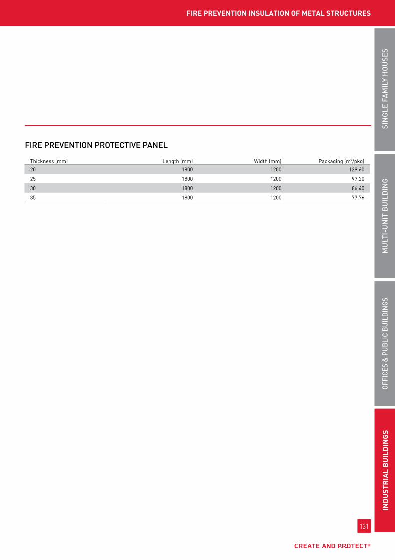
131
oFFI
CES
& P
uBL
IC B
uIL
DIn
gSM
uLt
I-u
nIt
Bu
ILD
Ing
SIn
gLE
FA
MIL
y H
ou
SES
InD
uSt
RIA
L B
uIL
DIn
gS
131
Ind
uSt
rIA
L b
uIL
dIn
gS
oFFI
CES
& P
uBL
IC B
uIL
DIn
gSM
uLt
I-u
nIt
Bu
ILD
Ing
SIn
gLE
FA
MIL
y H
ou
SES
fIrE prEVEntIon InSuLAtIon of MEtAL StruCturES
FIRE PREVEntIon PRotECtIVE PAnEL
thickness (mm) length (mm) width (mm) packaging (m2/pkg)
20 1800 1200 129.60
25 1800 1200 97.20
30 1800 1200 86.40
35 1800 1200 77.76

132
www.rockwool.fr
uSEfuL InforMAtIon
The following definitions explain the main certified criteria or those that determine the choice of an insulating material. You will find these values in the official document known as the ACERMI certificate.
tHErMALn thermal conductivity:definition: lambda, thermal conductivity of a material is the measurement of the flow of heat that passes through 1 m² of a 1-metre thick wall in one hour. It is expressed in watts per metre per degree celsius (w/m.°c) or kelvin (w/m.k).key point: the lower the thermal conductivity, the more insulating the material.further details: the thermal conductivity of an insulating material is defined in a general sense in the th rules and more specifically on the AcERmI certificate of the certified product.the value declared on the certificate is better than that defined in the th rules. It is therefore more appropriate to select a certified product.
n thermal resistance:definition: the thermal resistance of a construction material characterises its ability to slow down the movement of heat. thermal resistance is expressed in square-metre kelvins per watt.key point: the higher the value of R, the more insulating the material.further details: thermal resistance is the result of the calculation, certified by AcERmI from the thickness of the material and its thermal conductivity. this information, supplied by the manufacturer, is present on labels, price lists, technical data sheets, etc.
fIrE SAfEtyn reaction to fire:definition: the reaction to fire of a material characterises its capacity to ignite and thus contribute to the spread of the fire.key point: the more the material reacts to fire, the more it participates in the fire and thus to the fire development also known as 'flash over'.further details: the reaction to fire of construction products and, in particular, insulation materials, has been governed since 2002 by the European
EuRoclAss classification. this system comprises seven classes: A1, A2, b, c, D, E, and f:- class A1 is distinguished from the others by its
conclusive results in all tests and shows that the material is entirely incombustible. this new class has no equivalent in the old classification. It is above all the other classifications that previously existed.
- classes A2 and b correspond to non-combustible and low-combustible products.
- Euroclasses c, D and E correspond to combustible products. they characterise the construction products that are most hazardous in terms of fire behaviour.
- products classed in Euroclass f are not subject to any assessment of their performance. they can be subject to specific studies.
otHEr CHArACtErIStICSn Short term partial immersion water absorption wS:this is determined according to standard En 1609. no result must exceed 1.0 kg/m2.
n Long term water absorption wL(p):definition: Absorption is the penetration of a liquid or gaseous substance into a material.key point: the long term water absorption is an AcERmI certified characteristics allowing the water related performance of the insulation material to be determined.further details: the long-term water absorption of our ranges is determined in accordance with standard En12087. It consists of measuring the water retained by the material after a 28 day immersion period. this value must be less than 3kg/m² to consider that an insulation material does not retain water. Indication of this characteristic on the AcERmI certificate demonstrates that the result of the tests performed was positive.

133
n point Load pL(5)400:the point load required to cause a deformation of 5 mm must be determined in accordance with En 12430 and declared in 50 n increments. the results must not be less than the declared level (in the present case 400 n).
n Compressive Stress, CS(10/y)40:the compressive stress at 10% deformation must be determined in accordance with En826. no result must not be less than the declared level (in the present case 40 kpa).
n tension strength perpendicular to the faces tr10:this must be determined in accordance with standard En 1607. the results must not be less than the declared level (in the present case 10 kpa). n dimensional stability, dS (70,90):definition: Dimensional stability is the absence of variations in the dimensions of an item.key point: Dimensional stability is an AcERmI certified characteristic used to distinguish insulation that does not undergo dimensional variations under certain conditions.further details: the dimensional stability of our ranges shows that stone wool is not affected by temperature, humidity, pressure, etc.
n thickness tolerance:definition: thickness tolerance is the permissible limit of the differences in the thickness dimension of a material relative to their nominal dimension.key point: thickness tolerance is an AcERmI certified characteristic that is used to guarantee thickness.further details: the thickness tolerance of our ranges is determined in accordance with standard En 823. It consists of measuring thickness variation in mm or % under a given load. the result is expressed as t rating followed by a figure between 1 and 5, with the best tolerance level being 5.
n water vapour transmission Mu1:definition: transmission is the movement in space, without modification, of a physical phenomenon, force or energy.key point: water vapour transmission is an AcERmI-certified characteristic that is used to determine the movement of water vapour through the material in question.further details: the water vapour transmission of our ranges is determined in accordance with standard En 12086. It consists of determining the water vapour diffusion resistance coefficient.
ACouStICn Acoustic absorptionthe phenomenon of dissipation of acoustic energy by a material, caused by air friction in the pores of the material or its coupling to acoustic waves. n Acoustic attenuationDifference between the level of acoustic pressure measured at one point and the level measured at another point in the same space. n road traffic noise or road noisenoise likely to be generated by road traffic. the spectral composition of this noise is defined in the standards. n pink noiseconstant spectral density noise (the value is the same for each band of frequencies). n Acoustic absorption coefficientRatio of the sound energy absorbed by a material to the incident sound energy on that material. the value of this coefficient is therefore physically less than 1; however, the method used to present reverberant room measuring results generates, in line with standard Iso 354, some results above unity. n Acoustic attenuation ratiovalue that characterises the sound installation performance specific to a construction material or element. mathematically, this is the logarithm of the ratio of incident acoustic energy to the transmitted acoustic energy. n Acoustic insulationmaterial with a sound transmission loss in excess of 30 db. not to be confused with an acoustic absorber.- the architectural acoustic allows measurement
and control of a building's sound quality, with a view to comfort and well being. to make a space liveable it must be protected from noise and vibrations, by checking the emission and reception conditions for sound waves. In premises noise is propagated throughout the entire structure of the building.
- the internal acoustic is concerned with noise emitted inside the building, expressed by the absorbing power and the local reverberation duration, acoustic correction aims to control the sound energy reflected from the walls.
- the airborne noise insulation represents the difference in sound levels on either side of a wall. An airborne sound is emitted (for example, using a loudspeaker) on one side and its emitted sound level is measured. the received sound level is measured on the other side, and the air insulation of the wall being studied is obtained from the difference.
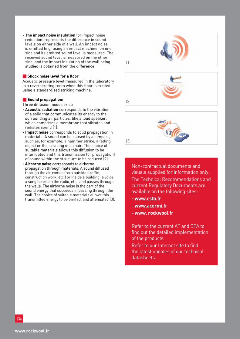
134
www.rockwool.fr
(3)
(1)
(2)
- the impact noise insulation (or impact noise reduction) represents the difference in sound levels on either side of a wall. An impact noise is emitted (e.g. using an impact machine) on one side and its emitted sound level is measured. the received sound level is measured on the other side, and the impact insulation of the wall being studied is obtained from the difference.
n Shock noise level for a floorAcoustic pressure level measured in the laboratory in a reverberating room when this floor is excited using a standardised striking machine. n Sound propagation: three diffusion modes exist:- Acoustic radiation corresponds to the vibration
of a solid that communicates its energy to the surrounding air particles, like a loud speaker, which comprises a membrane that vibrates and radiates sound (1).
- Impact noise corresponds to solid propagation in materials. A sound can be caused by an impact, such as, for example, a hammer strike, a falling object or the scraping of a chair. the choice of suitable materials allows this diffusion to be interrupted and this transmission (or propagation) of sound within the structure to be reduced (2).
- Airborne noise corresponds to airborne propagation through materials. A sound diffused through the air comes from outside (traffic, construction work, etc.) or inside a building (a voice, a song heard on the radio, etc.) and passes through the walls. the airborne noise is the part of the sound energy that succeeds in passing through the wall. the choice of suitable materials allows this transmitted energy to be limited, and attenuated (3).
non-contractual documents and visuals supplied for information only.the technical Recommendations and current Regulatory Documents are available on the following sites:- www.cstb.fr- www.acermi.fr- www. rockwool.fr Refer to the current At and DtA to find out the detailed implementation of the products.Refer to our Internet site to find the latest updates of our technical datasheets.

notES

notES


Export Catalogue
STONEwOOl iNSulaTiON SOluTiONS
rOckwOOl fraNcE S.a.S.
111, rue du Château des Rentiers
75013 Paris
Tel. +33 [0]1 40 77 82 82
fax. +33 [0]1 45 86 80 75
www.rockwool.fr
Non
con
trac
tual
doc
umen
t - P
rint
ed o
n pa
per
from
sus
tain
ably
man
aged
fore
sts
- Ja
nuar
y 20
14 -
Des
ign:
FD
C
ExP
oR
t C
ata
log
uE
Photograph this flashcode and find:n our product informationn our catalogues, our videosn and much more...