Embed Size (px)
Citation preview
Dynamics of Wicking in Silicon Nanopillars Fabricated withInterference Lithography and Metal-Assisted Chemical EtchingTrong Thi Mai,† Chang Quan Lai,‡ H. Zheng,† Karthik Balasubramanian,§ K. C. Leong,∥ P. S. Lee,§
Chengkuo Lee,† and W. K. Choi*,†,‡,⊥
†Department of Electrical and Computer Engineering, National University of Singapore, Singapore 117576‡Advanced Materials for Micro- and Nano-Systems Programme, Singapore−MIT Alliance, Singapore 117576§Department of Mechanical Engineering, National University of Singapore, Singapore 117576∥GLOBALFOUNDRIES Singapore Pte. Ltd, Singapore 738406⊥NUS Graduate School for Integrative Sciences and Engineering, National University of Singapore, Singapore 117456
*S Supporting Information
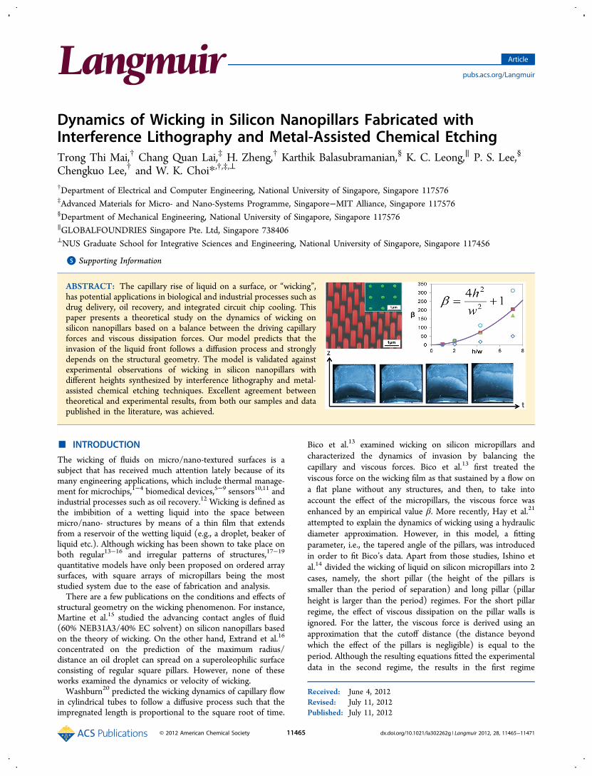
ABSTRACT: The capillary rise of liquid on a surface, or “wicking”,has potential applications in biological and industrial processes such asdrug delivery, oil recovery, and integrated circuit chip cooling. Thispaper presents a theoretical study on the dynamics of wicking onsilicon nanopillars based on a balance between the driving capillaryforces and viscous dissipation forces. Our model predicts that theinvasion of the liquid front follows a diffusion process and stronglydepends on the structural geometry. The model is validated againstexperimental observations of wicking in silicon nanopillars withdifferent heights synthesized by interference lithography and metal-assisted chemical etching techniques. Excellent agreement betweentheoretical and experimental results, from both our samples and datapublished in the literature, was achieved.
■ INTRODUCTION
The wicking of fluids on micro/nano-textured surfaces is asubject that has received much attention lately because of itsmany engineering applications, which include thermal manage-ment for microchips,1−4 biomedical devices,5−9 sensors10,11 andindustrial processes such as oil recovery.12 Wicking is defined asthe imbibition of a wetting liquid into the space betweenmicro/nano- structures by means of a thin film that extendsfrom a reservoir of the wetting liquid (e.g., a droplet, beaker ofliquid etc.). Although wicking has been shown to take place onboth regular13−16 and irregular patterns of structures,17−19
quantitative models have only been proposed on ordered arraysurfaces, with square arrays of micropillars being the moststudied system due to the ease of fabrication and analysis.There are a few publications on the conditions and effects of
structural geometry on the wicking phenomenon. For instance,Martine et al.15 studied the advancing contact angles of fluid(60% NEB31A3/40% EC solvent) on silicon nanopillars basedon the theory of wicking. On the other hand, Extrand et al.16
concentrated on the prediction of the maximum radius/distance an oil droplet can spread on a superoleophilic surfaceconsisting of regular square pillars. However, none of theseworks examined the dynamics or velocity of wicking.Washburn20 predicted the wicking dynamics of capillary flow
in cylindrical tubes to follow a diffusive process such that theimpregnated length is proportional to the square root of time.
Bico et al.13 examined wicking on silicon micropillars andcharacterized the dynamics of invasion by balancing thecapillary and viscous forces. Bico et al.13 first treated theviscous force on the wicking film as that sustained by a flow ona flat plane without any structures, and then, to take intoaccount the effect of the micropillars, the viscous force wasenhanced by an empirical value β. More recently, Hay et al.21
attempted to explain the dynamics of wicking using a hydraulicdiameter approximation. However, in this model, a fittingparameter, i.e., the tapered angle of the pillars, was introducedin order to fit Bico’s data. Apart from those studies, Ishino etal.14 divided the wicking of liquid on silicon micropillars into 2cases, namely, the short pillar (the height of the pillars issmaller than the period of separation) and long pillar (pillarheight is larger than the period) regimes. For the short pillarregime, the effect of viscous dissipation on the pillar walls isignored. For the latter, the viscous force is derived using anapproximation that the cutoff distance (the distance beyondwhich the effect of the pillars is negligible) is equal to theperiod. Although the resulting equations fitted the experimentaldata in the second regime, the results in the first regime
Received: June 4, 2012Revised: July 11, 2012Published: July 11, 2012
Article
pubs.acs.org/Langmuir
© 2012 American Chemical Society 11465 dx.doi.org/10.1021/la302262g | Langmuir 2012, 28, 11465−11471

deviated from theory. A comprehensive review on wicking canbe found in ref 22.Recently, we have discovered a simple method of creating
ordered arrays of silicon nanopillars over large areas (1 cm2) bymeans of interference lithography and metal-assisted chemicaletching (IL-MACE) method.23,24 The height of the nanopillarscan be easily varied by controlling the etching time. Theobjective of the present work is to examine the effect ofnanopillar geometry on the dynamics of wicking theoreticallyand to validate the theoretical predictions with experimentalresults obtained from our samples prepared by the IL-MACEmethod. We have also extended the comparison of theoreticalpredictions to data published in the literature.
■ EXPERIMENTAL DETAILSThe process flow for the synthesis of Si nanopillars using the IL-MACE technique is illustrated in Figure 1a. P-type (100) Si waferswere first cleaned by standard RCA1 and RCA2 processes and dippedin 10% HF for 1 min to remove native oxide. The Si wafers were thencoated with photoresist (Ultra-i 123) approximately 300 nm thick, andcured at 90 °C for 90 s. The photoresist was exposed using a Lloyd’s-mirror-type interference lithography setup with a HeCd laser source (λ= 325 nm).25 Two perpendicular exposures of 60 s duration were thenperformed on the samples, which was followed by a postbake at 110°C for 60 s. The exposed photoresist was removed using Microposit
MF CD-26 developer and circular-shape photoresist dots were formedon the Si surface. The samples were then subjected to an oxygenplasma etch (power of 200 W, oxygen pressure of 0.2 mbar, etchingtime of 30−45 s) to remove the residual photoresist on the Si surface,and to reduce the size of the photoresist dots. Au was thermallyevaporated on the substrate to a thickness of ∼30 nm, at a pressure of10−6 Torr. The photoresist dots were lifted off by ultrasonic bath inacetone for 15−20 min, leaving an Au mesh on the silicon surface. Thesamples were etched in a solution of H2O, HF, and H2O2 at roomtemperature for 5−30 min. The concentrations of HF and H2O2 were4.6 and 0.44 M, respectively. The samples were then immersed in astandard Au etchant for 5 min to remove Au and dried by a nitrogengun after rinsing in deionized water.
Figure 1b shows the scanning electron microscope (SEM) images ofsilicon nanopillars obtained with an FEI NOVA SEM230 instrument.All samples were fabricated with exactly the same conditions except forthe duration of etching (5−30 min), which gave the nanopillarsdifferent heights on different samples. Note that nanopillars fromsamples etched for 5−20 min are perfectly straight (see Figure 1b, iand ii). However, when the nanopillars become too tall (∼7 μm), thehigh aspect ratio causes the mechanical strength of the nanopillars tobe reduced significantly so that capillary forces can now overcome theelastic forces and cause sufficient permanent deformation/clumping ofthe nanopillars (see Figure 1b, iii).26
To examine the wicking characteristics, the samples were placedvertically, and a droplet (1 μL) of deionized water or silicone oil(HIVAC F4) was placed at the bottom of the sample surface. The
Figure 1. (a) Schematic diagram of the process flow for fabrication of Si nanopillars using the IL-MACE method. (b) SEM images of Si nanopillarswith heights of (i) ∼2 μm, (ii) ∼4 μm, and (iii) ∼7 μm, respectively. The insets are top-view SEM images of the respective samples. All samples inpart b have the same period of 1 μm.
Langmuir Article
dx.doi.org/10.1021/la302262g | Langmuir 2012, 28, 11465−1147111466

wicking process was recorded with a high speed camera (PhotronFastcam SA5) operating at 1000 frames per second and analyzed bymeans of software (Photron FASTCAM Viewer).
■ MODELBico et al.13 previously established the condition for wicking totake place as
θ θϕϕ
> =−−r
cos cos1
cs
s (1)
where θ is the contact angle the liquid makes with a flat surfaceof the substrate material, θc is the critical angle (0° ≤ θc ≤ 90°),r is the roughness of the textured surface (ratio of the actualsurface area to projected area) and ϕs is the ratio of the area ofthe top of the nanopillars (which was assumed to remain dry)to the projected area.In the case of our nanopillars,
π=+
+rdh
d s( )12
(2)
ϕ π=+d
d s4( )s
2
2(3)
where d is the diameter and h is the height of the nanopillars,and s is the spacing between nanopillars (i.e., the period of thenanopillars is d + s).The displacement of the wicking front with time was found
to follow the well-known diffusive relation
=z Dt( )1/2(4)
where z is the displacement of the wicking front, D is acoefficient independent of z and t, and t refers to the time afterthe start of wicking. Bico et al. derived D by assuming Poiseuilleflow and equating the driving capillary pressure for wicking withthe retarding pressure associated with viscous losses, obtaining
γμβ
θ θθ
=−
Dh2
3cos cos
cosc
c (5)
where γ is the surface tension of the liquid, μ is the viscosity ofthe liquid, and β is an empirically determined constant that ismultiplied with the viscous loss pressure derived from Poseuilleflow of a fluid of height h over a flat plane.13 The purpose ofthis multiplication is to account for the enhancement of viscouslosses due to the presence of micropillars on the plane.From eq 5, it can be seen that aside from topographical (h, β,
θc) and chemical parameters (θ) of the surface, the propertiesof the liquid (γ, μ) also play a role in determining the wickingvelocity. Because the driving pressure for wicking is propor-tional to γ and the viscous pressure retarding wicking isproportional to μ, wicking velocity is dependent on γ/μ. Thisdependence can be intuitively verified by considering the twoextreme cases, γ ≫ μ (e.g., water) and γ ≪ μ (e.g.,polydimethylsiloxane (PDMS)), which will result in very highand very low velocities, respectively.However, unlike values of γ and μ, which are readily available
for a wide range of liquids, β has to be experimentallydetermined and as a result, D in eq 5 cannot be fully predictedwith theory alone. Thus, it is difficult to gain a full insight ofhow geometrical parameters of the nanopillars affect D, whichin turn determines the wicking kinematics. In this paper, we
attempt to derive an analytical solution for β and verify thatwith experimental data.To simplify the derivation, we start by approximating the
flow of fluid through the nanopillars as flow through opennanochannels that are of the same height, h, and length, (d + s),as a unit cell of nanopillar as shown in Figure 2. A unit cell of
nanochannel can hold the same volume of fluid as a unit cell ofnanopillar and, thus, the width of the nanochannel, w, can becalculated to be
π=+ −
+= − + +
+
π⎡⎣ ⎤⎦w
d s d h
d s hd ds s
d s
( )
( )(4 ) 8 4
4( )
24
2 2 2
(6)
For steady state, incompressible flow in the z-directionthrough an open channel such as that shown in Figure 2c andignoring gravitational effects, which are relatively insignificant atthe scale of our experiments,13 the Navier−Stokes’ equation canbe reduced to
μ− Δ = ∂
∂+ ∂
∂
⎛⎝⎜
⎞⎠⎟
Pz
Ux
Uy
2
2
2
2(7)
where ΔP is the capillary pressure driving the flow and U(x,y) isthe velocity profile. Following Bico et al.’s derivation, (ΔP)/z isindependent of x and y and, thus, when eq 7 is solved with theboundary conditions
=U y(0, ) 0 (8.1)
=U x( , 0) 0 (8.2)
=U w y( , ) 0 (8.3)
=U x h( , 2 ) 0 (8.4)
the velocity profile can be given as
Figure 2. Approximating a unit cell (indicated by dashed black lines)of nanopillars as a unit cell of nanochannel that holds the same volumeof liquid. (a) Top view of a unit cell; (b,c) top view and side view of ananochannel. The yellow regions indicate the top of the nanostruc-tures at y = h, which remain dry throughout the wicking process, whilethe violet regions indicate the bottom regions at y = 0. Flow of fluid isin the z-direction in all cases.
Langmuir Article
dx.doi.org/10.1021/la302262g | Langmuir 2012, 28, 11465−1147111467

∑π μ
π π
=Δ
+ + +
+ +
=
∞
+ +⎡⎣⎢
⎤⎦⎥
U x y
P
m n z
m xw
n yh
( , )
16
(2 1)(2 1)
sin(2 1)
sin(2 1)
2
m nm
wn
h, 0
(2 1) (2 1)4
42
2
2
2
(9)
Details of the derivation of eq 9 can be found in SI.1 of theSupporting Information. Averaging U(x,y) over the area of (w× h) to find the mean velocity Umean, we obtain
∑
∫ ∫
π μ
=
= Δ
+ + +=
∞
+ +⎡⎣⎢
⎤⎦⎥
UU x y x y
whP
m n z
( , ) d d
64
(2 1) (2 1)
h w
m n mw
nh
mean0 0
, 0 (2 1) (2 1)4
2 2 62
2
2
2
(10)
Since the value of each term in the summation series in eq 10decreases exponentially with increasing m or n, we canapproximate Umean by considering only the first term (m = 0,n = 0) of the summation series which contributes the most tothe value of Umean. We have carried out a systematic analysis ofthe effect on the contribution of other terms (where m > 1 andn > 1) in eq 10 and found that our assumption to only considerthe first term in the summation series is justified. Details of thisanalysis can be found in SI.2 of the Supporting Information.To take into account the value added to Umean by the rest of
the terms, we multiply by a constant C to approximate the valueof Umean. Thus, we have
π μ≈ Δ
+⎡⎣ ⎤⎦U C
P
z
64
w h
mean 1 14
62 2 (11)
To find C, we consider the extreme case where w approachesinfinity. In this instance, the flow of fluid is equivalent to flowon a flat plane, and, thus, eq 11 will be reduced to Poiseuilleflow over a flat plane, which is given by13
μ= Δ
UPh
z3mean
2
(12)
Equating eq 11 when w → ∞ and eq 12, we find that C = π6/768. Substituting this into eq 11 we obtain
μ≈ Δ
+U
Ph wz w h3 [ 4 ]mean
2 2
2 2 (13)
Finally, by comparing eq 13 with the mean velocity derived byBico et al. (Umean = (ΔPh2)/(3βμz)),13 we arrive at anexpression for β as
β = +hw4
12
2 (14)
From eqs 6 and 14, it can be seen that when the surfaceapproaches a flat topography (s≫ d and s≫ h; h≪ d and h≪s), β approaches 1, i.e., the flow approaches Poiseuille’s flow ona flat plane. On the other hand, when the surface approaches avery rough texture (h ≫ d and h ≫ s), β approaches infinity,which is to be expected, taking into consideration the enormousviscous losses associated with very tall or very dense arrays ofpillars. Note that this does not necessarily mean that wickingspeed will be very low, as the geometric parameters also
influence the driving pressure for wicking. This will bediscussed in more details later in the paper. For now, weconsider another case, d ≫ s, for which β will become inverselyrelated to d. This can be explained by considering theinterstitial spaces formed when a rectangular array of cylindricalpillars join up; as the size of these pillars increase, the interstitialspaces for wicking to take place become more spacious anddeterrence to wicking falls. In the extreme case where d ≫ h, βapproaches 1 as viscous losses to the sidewalls of the pillarsbecome negligible and the flow returns to one on a flat plane.Extending eq 6 to square pillars so that w = (ds/(d + s)) + s, itis easy to see that for the same case of d ≫ s, β is now inverselyrelated to s instead. This is not surprising because unlikecylindrical pillars, there are no interstitial spaces when squarepillars join up. As a result, the flow becomes more constricted(higher β) as s decreases, and in the extreme case where s = 0, βapproaches infinity, which is consistent with the expectationthat wicking cannot occur on a flat surface.13 The aboveconsiderations show that eq 14 supports common, intuitiveknowledge of wicking for limiting cases, thereby providing apreliminary verification of the validity and versatility of eq 14.We will revisit eq 14 later in this paper when we compare thetheoretical to experimental values of β.
■ RESULTS AND DISCUSSIONOn the basis of eqs 1−3, we have calculated the critical contactangles for our samples, and the values are listed in Table 1.
Having found that the contact angles for water and silicone oilon flat silicon substrate are θwater = 56.3° and θoil = 18.0°,respectively, we are able to verify that Bico et al.’s condition forwicking (θc > θ) agrees with our experiments. Water andsilicone oil were able to wick in all the samples except sample A(for water only), which had a critical angle that is fairly close tothe contact angle of water on a flat silicon surface. Since thedriving pressure for wicking13 is proportional to (cos θ − cosθc)/cos θc, it is not surprising to find that wicking may notoccur at all when cos θ ≈ cos θc, especially in the presence ofslight surface defects or impurities, which tend to raise theenergy cost of wicking.Next, we study the wetting properties of the silicon
nanopillars surfaces by examining the wicking dynamics ofsilicone oil (γ = 3.399 × 10⁻² N/m, μ = 3.94 × 10⁻² Pas, θoil =18°)27 and water (γ = 7.28 × 10⁻² N/m, μ = 8.9 × 10⁻³ Pas,θwater = 56.32°). Figure 3 shows photographs of the spreadingof 1 μL oil droplet pipetted onto an upright silicon substratewith nanopillar texture on its surface. The liquid reached thetop of the sample (which is about 8 mm in height) in about 300s. For water, the wicking was much faster, and it reached theend of the sample in about 10s. The videos of the wicking ofwater and silicone oil are provided in the SupportingInformation as “Video-Water” and “Video-Oil”, respectively.
Table 1. Critical Contact Angle (θc) for Silicon NanopillarsFabricated by the IL-MACE Method
etch time(mins)
diameter(μm)
height(μm) ϕs r θc (
o)
pillar A 5 0.275 0.75 0.043 1.897 59.62pillar B 10 0.300 2.00 0.064 2.710 69.28pillar C 20 0.300 4.20 0.064 4.590 78.07pillar D 30 0.300 7.00 0.064 6.984 82.23
Langmuir Article
dx.doi.org/10.1021/la302262g | Langmuir 2012, 28, 11465−1147111468

The difference in the wicking speed can be accounted for by thedifference in γ/μ (see eq 5) of the two liquids.Figure 4 shows plots of distance traveled by the wetting front
versus the square root of time (i.e., z vs t1/2) for all our samples.
As with previous studies,13,18,19 the linear trendlines do notcontinue through the point of origin. This deviation in the earlystages of wicking may be due to the influence of other processesthat are observed to take place right before or during the onsetof wicking (e.g., droplet spreading). Note that the viscousenhancement factor β can be obtained by measuring thegradient of this plot (i.e., the value of D1/2) and substituting thevalue into eq 5.The calculated (from eq 14) and experimentally determined
values of β are plotted in Figure 5. As can be seen from thisfigure, our theoretical values for β agree very well with theexperimental data over a wide spectrum of h/w values. Notealso that the empirical values of β obtained with water andsilicone oil are very close, thus proving that β is independent offluid properties, as predicted by eq 14. The only exception tothis is the data point at h/w = 7.1 where β (water) deviatesfrom β (silicone oil). This difference is likely due to thedeformations of the mechanically weak, high aspect ratio (≈23)nanopillars caused by capillary forces during the wickingprocess (see Figure 1b, iii).In Figure 5, we also show the β values calculated for our
samples based on the models proposed by Ishino et al.14 andZhang et al.1 We have taken Umean reported in these papers andcompared with Bico’s expression (Umean = (ΔPh2)/(3βμz)) toobtain β. This will give
βϕ
=−
< +h d s1
1for ( )
s (15.1)
β π
ϕ=
− + −
> +
+⎡⎣ ⎤⎦( )h
d s
h d s
4
3(1 )( ) ln 1.31for
( )
d sd
2
s2 2 2
(15.2)
for Ishino et al.’s14 derivation, and
β =+dh
d s4
( )
2
2(16)
for Zhang et al.’s1 derivation.It can be observed that Zhang et al.’s approximation for β
underestimates its true value for all h/w, while Ishino et al.’sexpressions overestimate the experimental β at high h/w (≥4)but underestimate it at low h/w (<2). The reason for thedeviations can be attributed to the models that wereconsidered. For instance, Zhang et al. estimated the flowbetween the pillars to be Poiseuille’s flow between two parallelplates (the pillars being the plates) and ignored thecontribution to the viscous losses by the floor at y = 0. Inaddition, viscous losses were only considered to occur when theflow occurs between two pillars. However, the velocity profilewhen the flow proceeds past the channels between adjacentpillars is not expected to be spatially constant, and thus there
Figure 3. Snapshots of the wicking process of silicone oil on silicon nanopillar surface (sample B). The red dotted line marks the liquid front.
Figure 4. Plot of distance traveled by the wetting front against thesquare root of time for nanopillars wetted with silicone oil (γ = 3.399× 10⁻² N/m, μ = 3.94 × 10⁻² Pas, θoil = 18°).
Figure 5. Experimental and calculated values of β. Data points for β(silicone oil) and β (water) are obtained with silicone oil and water,respectively. Calculation based on our method is represented by a solidline. Also shown in this figure are the calculated β values of oursamples based on the models of Zhang et al.1 and Ishino et al.14
Langmuir Article
dx.doi.org/10.1021/la302262g | Langmuir 2012, 28, 11465−1147111469

should also be shear losses involved in those regions. For thesereasons, the β values determined from Zhang et al.’s model arelower than the experimental values. As for Ishino et al.’smethod, when h < (d+s), the flow between micropillars isassumed to be similar to flow over a flat plane. In this case, it isexpected that the calculated β values should be smaller than theexperimental values because the effect of micropillars onviscous losses was not considered. For h > (d+s), Ishino et al.suggested that the micropillars can be considered to be infinite,and thus the calculated β values are anticipated to be larger thanthe actual values.To further validate our theory, we calculate the β values for
the micropillars reported by Ishino et al.14 The theoreticalpredictions by Ishino et al. and Zhang et al. are presentedalongside our calculated β values and the experimental data forcomparison purposes. The results are plotted in Figure 6. It can
be seen that our model fits Ishino et al.’s experimental data verywell, and shows a significant improvement over Ishino et al.’stheoretical estimation of β values when h is small. Interestingly,our theory (eq 14) and Ishino et al.’s model (eq 15.2) convergewhen h increases. However, this is only coincidental as it can beproven mathematically that this is not true for all d and s values.In addition, Ishino et al.’s results agree with our conclusion thatβ is independent of the properties of the test fluid.Our model (eq 14) can also be employed to solve an
observation previously made by Ishino et al., namely, thediffusion coefficient D becomes increasingly independent ofnanopillar height, h, as h becomes very large. By considering h≫ d, s, w in eqs 1−3 and 14, it can be shown that (cosθ − cosθc)/cos θc ∼ h and β ∼ h2. Therefore, from eq 5, D willapproach a constant value. This means that when the micro/nanopillars are short, the capillary driving force for wicking isincreased more than viscous losses (represented by β) withincreasing pillar height, thus resulting in faster wicking velocity.However, as the pillars become taller, the viscous force isincreasing as fast as the capillary driving force with increasingheight, and therefore a maximum speed will be reached. Theunderstanding that wicking velocity cannot be endlessly
improved by increasing h has important implications for thedesigning of engineering applications based on wicking and isone of the many insights that can be derived from this model.
■ CONCLUSIONSWe presented in this paper a theoretical study and anexperimental validation of the wicking dynamics on a squarearray of silicon nanopillars. The enhancement factor of viscouslosses, β, due to the presence of nanopillars was investigatedand was found to depend on the ratio of h/w where w is thewidth of the channel that is used to approximate the wickingflow through nanostructures. Our expression for β was alsofound to be applicable to published results obtained by othergroups.The success in describing the dynamics of wicking explicitly
without any empirical parameters means that the wickingproperty (i.e., speed) of a particular material can be adjusted bysimply controlling the geometry (e.g., height) of the texturedsurface. However, there is a limit when using the height ofmicro/nanostructures to do so, as the wicking speed willapproach an asymptotic value when the height of the structuresbecomes much greater than the other dimensions. Theseinsights are most valuable for the designing of future wickingapplications.
■ ASSOCIATED CONTENT*S Supporting InformationThe Supporting Information provides derivations of theequations in the text as well as additional analysis. Videos inAVI format showing the wicking of silicone oil and water areavailable. This information is available free of charge via theInternet at http://pubs.acs.org.
■ AUTHOR INFORMATIONCorresponding Author*E-mail: [email protected] ContributionsThe manuscript was written through contributions of allauthors.NotesThe authors declare no competing financial interest.
■ ACKNOWLEDGMENTSThe authors would like to acknowledge the partial funding ofthis work by the Singapore−MIT Alliance. T.T.M., C.Q.L., andH.Z. would like to express their deepest gratitude to theNational University of Singapore, Singapore−MIT Alliance,and GLOBALFOUNDRIES for provision of research scholar-ships.
■ REFERENCES(1) Zhang, C.; Hidrovo, C. H. Investigation of Nanopillar WickingCapabilities for Heat Pipes Applications. ASME 2009 Second Int. Conf.Micro/Nanoscale Heat Mass Transfer 2009, 3, 423−437.(2) Ding, C.; Bozorgi, P.; Meinhart, C. D.; MacDonald, N. C.Wicking Optimization for Thermal Cooling. Hiltonhead Conference2010, Solid-State Sens., Actuators, Microsyst. Workshop 2010, 376.(3) Oshman, C.; Li, Q.; Liew, L.-A.; Yang, R.; Lee, Y. C.; Bright, V.M.; Sharar, D. J.; Jankowski, N. R.; Morgan, B. C. ThermalPerformance of a Flat Polymer Heat Pipe Heat Spreader UnderHigh Acceleration. J Micromech. Microeng. 2012, 22, 045018.(4) Kang, S.-W.; Tsai, S.-H.; Ko, M.-H. Metallic Micro Heat PipeHeat Spreader Fabrication. Appl. Therm. Eng. 2004, 24, 299−309.
Figure 6. Comparison of β values obtained by our method and othermodels for the experimental data presented in Ishino et al.’s paper.Experimental and theoretical values are plotted as points and lines,respectively. Our model is represented by the solid blue line. Fivedifferent test liquids (γ = 2 × 10⁻² N/m) were used, and theirrespective viscosities are given in the legend. d = 2 μm and s = 8 μmremained constant for all experiments.
Langmuir Article
dx.doi.org/10.1021/la302262g | Langmuir 2012, 28, 11465−1147111470

(5) Pararas, E. E. L.; Borkholder, D. A.; Borenstein, J. T.Microsystems Technologies for Drug Delivery to the Inner Ear. Adv.Drug Delivery Rev. 2012, DOI: 10.1016/j.addr.2012.02.004.(6) Guillaume, D. W.; DeVries, D. Improving the PneumaticNebulizer by Shaping the Discharge of the Capillary Wick. J. Biomed.Eng. 1991, 13, 526−528.(7) Liu, C.; Mauk, M. G.; Hart, R.; Qiu, X.; Bau, H. H. A Self-HeatingCartridge for Molecular Diagnostics. Lab Chip 2011, 11, 2686−2692.(8) Araujo, A. C.; Song, Y.; Lundeberg, J.; Stahl, P. L.; Brumer, H.Activated Paper Surfaces for the Rapid Hybridization of DNA throughCapillary Transport. Anal. Chem. 2012, 84, 3311−3317.(9) Lankelma, J.; Nie, Z.; Carrilho, E.; Whitesides, G. M. Paper-BasedAnalytical Device for Electrochemical Flow-Injection Analysis ofGlucose in Urine. Anal. Chem. 2012, 84, 4147−4152.(10) Lazarus, N.; Bedair, S. S.; Lo, C.-C.; Fedder, G. K. CMOS-MEMS Capacitive Humidity Sensor. J. Microelectromech. Syst. 2010, 19,183−191.(11) Peng, P.; Summers, L.; Rodriguez, A.; Garnier, G. ColloidsEngineering and Filtration to Enhance the Sensitivity of Paper-BasedBiosensors. Colloids Surf. B 2011, 88, 271−278.(12) Feng, X. J.; Jiang, L. Design and Creation of Superwetting/Antiwetting Surfaces. Adv. Mater. 2006, 18, 3063−3078.(13) Bico, J.; Tordeux, C.; Quere, D. Rough Wetting. Europhys. Lett.2001, 55, 214−220.(14) Ishino, C.; Reyssat, M.; Reyssat, E.; Okumura, K.; Quere, D.Wicking within Forests of Micropillars. Europhys. Lett. 2007, 79,56005.(15) Martines, E.; Seunarine, K.; Morgan, H.; Gadegaard, N.;Wilkinson, C. D. W.; Riehle, M. O. Superhydrophobicity andSuperhydrophilicity of Regular Nanopatterns. Nano Lett. 2005, 5,2097−2103.(16) Extrand, C. W.; Moon, S. I.; Hall, P.; Schmidt, D. Superwettingof Structured Surfaces. Langmuir 2007, 23, 8882−8890.(17) Ahn, H. S.; Park, G.; Kim, J.; Kim, M. H. Wicking and Spreadingof Water Droplets on Nanotubes. Langmuir 2012, 28, 2614−2619.(18) Vorobyev, A. Y.; Chunlei, G. Laser Turns Silicon Superwicking.Opt. Exp. 2010, 18, 6455−6460.(19) Vorobyev, A. Y.; Chunlei, G. Water Sprints Uphill on Glass. J.Appl. Phys. 2010, 108, 123512.(20) Washburn, E. W. The Dynamics of Capillary Flow. Phys. Rev.1921, 17, 273−283.(21) Hay, K. M.; Dragila, M. I.; Liburdy, J. Theoretical Model for theWetting of a Rough Surface. J. Colloid Interface Sci. 2008, 325, 472−477.(22) Quere, D. Wetting and Roughness. Annu. Rev. Mater. Res. 2008,38, 71−99.(23) Choi, W. K.; Liew, T. H.; Dawood, M. K.; Smith, H. I.;Thompson, C. V.; Hong, M. H. Synthesis of Silicon Nanowires andNanofin Arrays Using Interference Lithography and Catalytic Etching.Nano Lett. 2008, 8, 3799−3802.(24) Dawood, M. K.; Liew, T. H.; Lianto, P.; Hong, M. H.; Tripathy,S.; Thong, J. T. L.; Choi, W. K. Interference Lithographically Definedand Catalytically Etched, Large-Area Silicon Nanocones fromNanowires. Nanotechnology 2010, 21, 205305.(25) Savas, T. A.; Schattenburg, M. L.; Carter, J. M.; Smith, H. I.Large-Area Achromatic Interferometric Lithography for 100 nmPeriod Gratings and Grids. J. Vac. Sci. Technol. 1996, B14, 4167−4170.(26) Dawood, M. K.; Zheng, H; Kurniawan, N. A.; Leong, K. C.;Foo, Y. L.; Rajagopalan, R.; Khan, S. A.; Choi, W. K. Modulation ofSurface Wettability of Superhydrophobic Substrates using Si NanowireArrays and Capillary-Force-Induced Nanocohesion. Soft Matter 2012,8, 3549−3557.(27) Data sheet for silicone oil. http://www.silicone.jp/e/products/type/oil/index.shtml.
Langmuir Article
dx.doi.org/10.1021/la302262g | Langmuir 2012, 28, 11465−1147111471