Embed Size (px)
Citation preview
4th International Conference on Earthquake Geotechnical Engineering
June 25-28, 2007 Paper No.1336
DYNAMIC PILE BEHAVIORS AFFECTED BY LIQUEFACTION FROM
EQWEAP ANALYSIS
D. W. Chang 1, B. S. Lin2 and S. H. Cheng3
ABSTRACT The liquefaction induced pile responses have attracted research attentions for many years. Modern geotechnical performance-based design codes therefore require proper structural analyses to predict deformations and stresses of the piles during earthquake. With these regards, this paper suggests a simplified but effective procedure called EQWEAP for the modeling. In such procedure, seismic ground motions of a free-field site, where the possible liquefaction effects might occur, were first calculated from one-dimensional lumped mass model. The ground displacements were then used to solve the discrete wave equations to obtain the corresponding pile displacements. To procure better solutions, excess pore pressure from the empirical model was carefully calibrated with considering the liquefaction potential of the soils. A couple of case studies based on pile foundation failures reported on the Niigata earthquake in 1964 were conducted to see the applicability of this procedure. Overall, this solution, which is quite simple though, can predict the pile responses due to the soil liquefaction. Keywords: pile foundation, seismic response, liquefaction, wave equation analysis
INTRODUCTION The earthquake-caused liquefied soils can result in considerable loss in the soils’ resistances to the pile. The effects of soil liquefaction and liquefaction induced ground flow have attracted tremendous research attentions in recent years. Excellent simulations can be found in the papers presented in 2005 UC Davis workshop on seismic performance of pile foundation in liquefied and laterally spreading ground. Although the dynamic and effective stress analysis using the complete finite element method is rigorous enough to solve the problem, however, it is relatively time-consuming and complicated for routine design work as compared with the simplified dynamic solution. The later (Boulanger et al., 1999; Wilson et al., 2000; Brandenderg et al., 2005) was thus suggested based on the dynamic Winkler’s foundation model of the pile analyzed through one dimensional finite element segments. More recently, alternative pseudo static solutions of the Winkler’s foundation model were also found in Arduino et al. (2005), Liyabapathirana and Poulos (2005) and Lin et al. (2005). In all these simplified approaches, seismic ground motions, without exception, need to be computed first in order to obtain the corresponding pile response. Further, the soil liquefaction induced ground motions can be modeled through either the use of simple reduction factors for the soil parameters or a more rigorous model in which the excess pore 1 Professor, Department of Civil Engineering, University of Tamkang, Tamsui, Taiwan 25137, ROC.
Email: [email protected] 2 Research Assistant, Department of Civil Engineering, University of Tamkang, Tamsui, Taiwan
25137, ROC. Email: [email protected] 3 Research Assistant, Department of Civil Engineering, University of Tamkang, Tamsui, Taiwan
25137, ROC. Email: [email protected]
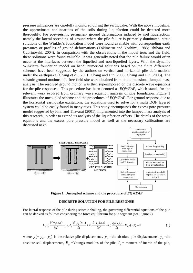
pressure influences are carefully monitored during the earthquake. With the above modeling, the approximate nonlinearities of the soils during liquefaction could be detected more thoroughly. For post-seismic permanent ground deformations induced by soil liquefaction, namely the lateral spreading of ground where the pile failure is primarily dominated, static solutions of the Winkler’s foundation model were found available with corresponding earth pressures or profiles of ground deformations (Tokimatsu and Yoshimi, 1983; Ishihara and Cubrinovski, 2004). In comparison with the observations in the model tests and the field, these solutions were found valuable. It was generally noted that the pile failure would often occur at the interfaces between the liquefied and non-liquefied layers. With the dynamic Winkler’s foundation model on hand, numerical solutions based on the finite difference schemes have been suggested by the authors on vertical and horizontal pile deformations under the earthquake (Chang et al., 2001; Chang and Lin, 2003; Chang and Lin, 2006). The seismic ground motions of a free-field site were obtained from one-dimensional lumped mass analysis. The resolved ground motion was then superimposed on the discrete wave equations for the pile responses. This procedure has been denoted as EQWEAP, which stands for the relevant work evolved from ordinary wave equation analysis of pile foundation. Figure 1 illustrates the uncoupled scheme and the procedures of EQWEAP. For ground response due to the horizontal earthquake excitations, the equations used to solve for a multi DOF layered system could be easily found in many texts. This study encompasses the excess pore pressure model suggested by Finn and Thavaraj (2001), implemented into the lumped mass analysis of this research, in order to extend its analysis of the liquefaction effects. The details of the wave equations and the excess pore pressure model as well as the necessary calibrations are discussed next.
Figure 1. Uncoupled scheme and the procedure of EQWEAP
DISCRETE SOLUTION FOR PILE RESPONSE For lateral response of the pile during seismic shaking, the governing differential equations of the pile can be derived as follows considering the force equilibrium for pile segment (see Figure 2)
4 2 2
4 2 2
( , ) ( , ) ( , ) ( , ) ( , ) 0p p pp p p p x s s
y x t y x t y x t y x tE I A P C K y x ttx t x
ρ∂ ∂ ∂ ∂
+ + + + =∂∂ ∂ ∂
(1)
where )( sp yyy −= is the relative pile displacements, py =the absolute pile displacements, sy =the
absolute soil displacements, pE =Young's modulus of the pile; pI = moment of inertia of the pile,
FREE FIELD RESPONSE
LUMPED-MASS SOLUTION WEA FOR SEISMIC MOTIONS
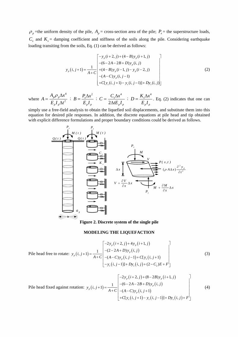
pρ =the uniform density of the pile, pA = cross-section area of the pile; xP = the superstructure loads,
sC and sK = damping coefficient and stiffness of the soils along the pile. Considering earthquake loading transiting from the soils, Eq. (1) can be derived as follows:
( )
( 2, ) (4 ) ( 1, )
(6 2 2 ) ( , )1, 1 (4 ) ( 1, ) ( 2, )
( ) ( , 1)
[ ( , 1) ( , 1)] ( , )
p p
p
p p p
p
s s s
y i j B y i jA B D y i j
y i j B y i j y i jA C
A C y i jC y i j y i j Dy i j
− + + − +⎡ ⎤⎢ ⎥− − − +⎢ ⎥⎢ ⎥+ = + − − − −⎢ ⎥+⎢ ⎥− − −⎢ ⎥+ + − − +⎢ ⎥⎣ ⎦
(2)
where 2
4
tIExA
App
pp
Δ
Δ=
ρ;
pp
x
IExPB
2Δ= ;
pp
s
ItExCC
ΔΔ
=2
4
;pp
s
IExKD
4Δ= . Eq. (2) indicates that one can
simply use a free-field analysis to obtain the liquefied soil displacements, and substitute them into this equation for desired pile responses. In addition, the discrete equations at pile head and tip obtained with explicit difference formulations and proper boundary conditions could be derived as follows.
Figure 2. Discrete system of the single pile
MODELING THE LIQUEFACTION
Pile head free to rotate: ( )
( ) ( )( )
( ) ( )( ) ( ) 2
2 2, 4 1,
(2 2 ) ,1, 1( ) , 1 [ , 1
, 1 ] , (2 )
p p
pp
p s
s s
y i j y i j
A D y i jy i j
A C A C y i j C y i j
y i j Dy i j C E F
⎡− + + + ⎤⎢ ⎥− − +⎢ ⎥
+ = ⎢ ⎥+ − − − + +⎢ ⎥⎢ ⎥− − + + − +⎣ ⎦
(3)
Pile head fixed against rotation: ( )
( ) ( )( )
( )( ) ( ) ( )
2 2, (8 2 ) 1,
(6 2 2 ) ,1, 1( ) , 1
[ , 1 , 1 ] ,
p p
pp
p
s s s
y i j B y i j
A B D y i jy i j
A C A C y i j
C y i j y i j Dy i j F
⎡− + + − + ⎤⎢ ⎥− − − +⎢ ⎥
+ = ⎢ ⎥+ − − +⎢ ⎥⎢ ⎥+ + − − + +⎣ ⎦
(4)
sK
sC
xPxP
)t(M )t(M
)t(Q )t(Q
xΔ
xP
xP
M
V
VV xx
∂+ Δ
∂ MM xx
∂+ Δ
∂
)t,x(P2
2( ) pyA x
tρ
∂Δ
∂
ga

Pile tip assumed to be long pile: ( )( ) ( )
( ) ( )( ) ( ) ( )
(2 2 2) , (4 2 ) 1,1, 1 2 2, ( ) , 1
[ , 1 , 1 ] ,
p p
p p p
s s s
A B D y i j B y i j
y i j y i j A C y i jA C
C y i j y i j Dy i j
+ − − + − −⎡ ⎤⎢ ⎥
+ = − − − − −⎢ ⎥+ ⎢ ⎥+ + − − +⎣ ⎦
(5)
where 2
t
p p
M xE
E IΔ
= ;32 t
p p
x PF
E IΔ
= ; tM and tP are the external moment and load applied at the pile
head. The discrete equations have the advantage that no matrix analysis is required. The equations can be independently solved in a short time to obtain the pile responses. The empirical model suggested by Martin et al. (1975), Finn et al. (1977), Finn and Thavaraj (2001) on excess pore pressure generation during the earthquake is adopted herein to obtain the free-field ground response. The model for soils at undrained condition is simply described as follows.
1
vd
p
r w
un
E K
εΔΔ =
+ (6)
where uΔ = excess pore water pressure; vdεΔ = increment in volumetric strain; rE = one dimensional rebound modulus at an effective stress v'σ ;
pn = porosity, and wK is the bulk modulus of water. For saturated sand rw EK >> , the excess pore pressure could be simplified as follows. r vdu E εΔ = Δ (7) According to simple shear test, the volumetric strain increment ( vdεΔ ) is a function of the total accumulated volumetric strain ( vdε ) and the shear strain (γ ). The relationship has the form given by
2
3 [ 1][ ] 1 2 [ 1]
4 [ 1]
( ) vd ivd i vd i
vd i
CC C
Cε
ε γ εγ ε
−−
−
Δ = − ++
(8)
[ ] [ ]1
n
vd n vd ii
ε ε=
= Δ∑ (9)
where [i] = ith time step or cycle; and 1C , 2C , 3C , and 4C are constants depending on the soil type
and relative density. Analytical expression for rebound modulus ( rE ) at any effective stress level ( v'σ ) is given by
' 1
'0
2
( )( )
mm nv
r vEmkσ
σ−
−= (10)
where '
0vσ is initial value of the effective stress; and 2k , m and n are experimental constants for the given sand. The calculations of the excess pore pressure were then used in conjunction with following equations in which the soil moduli are analyzed. Shear modulus of the soil is determined from the equation given by Seed and Idriss (1970), i.e., 0.5
21000 ( ' )mG K σ= (11)
where 2K is a parameter varying with shear strain and m'σ is the mean effective stress. G is iteratively modified with the shear strain and effective mean stress according to the excess pore pressure generated during the seismic shaking. The equilibrium of the system is ensured for the convergence of the iterations. To have better control the excess pore pressures prediction for soils at deep depths, one can use the following formula (Tokimatsu and Yoshimi, 1983) to calibrate the excess pore pressure from pre-analyzed liquefaction potential of the soil. In that case, the pore pressure ratio ( ur ) can be defined as a function of factor of safety against liquefaction LF , written as follows.
1 1
111 1 sin (2 1)
2u Lr F α β
π−= + − (12)
where 1α , 1β are the experienced constants.
APPLICATIONS WITH CASE STUDIES Case histories of the pile foundation failures in 1964 Niigata earthquake reported by Hamada (1992) were selected to see the applicability of proposed procedure. The field investigation had shown that the large ground displacements and the pile failure were found where the soil liquefaction appeared to be the causative problem. As it was pointed out that the pile response is primarily dominated by the permanent ground deformations whereas the proposed solution could not work properly, one could become interested to see the comparisons between the report and the proposed solutions as well as the data presented by others. In the following studies, piles were assumed elastic while soil nonlinearities were approximated using the excess pore pressure model. Case I - Niigata Family Court House, Japan The Niigata Family Court House was a four-story building located on the left bank of the Shinano River. The building was founded on concrete piles (see Figure 3(a)) with diameter of 35 cm and length of 6 to 9 m. During the earthquake, the pile foundations were damaged by liquefaction-induced ground displacement. Excavation surveys had shown that two piles (No.1 pile and No.2 pile) had severe cracks (see Figure 3(b)). Supposedly, they were crushed at the excessive bending moments at the interface between the liquefied and non-liquefied layers. According to Hamada’s report, the permanent ground displacement in the vicinity of building moved approximately by 1.1m and the maximum displacement of No.1 pile and No.2 pile were respectively 50 cm and 70cm. To be concise, the entire soil system is assumed as two layers. The upper layer from the ground surface to the depth of 8m is classified as medium-dense sand, whereas the lower layer from the depth of 8 to 11m is classified as dense sand. All the soil and pile properties are listed in Table 1. The acceleration time history for the NS-component of the earthquake is illustrated in Figure 4. The initial shear modulus of the soils was calculated and presented in Figure 5(a). The variation of the shear modulus is similar to the Gibson profile. One can conduct lumped mass analysis to obtain the ground response considering the effects of liquefaction. The pore water pressure ratios versus the depths from the liquefaction potential analysis are illustrated in Figures 6. The pore pressure ratio pressure ( ur ) associated with the factor of safety against liquefaction was evaluated using the liquefaction potential method suggested by Tokimatsu and Yoshimi (1983). Figure 7 shows the time histories of ground motions. It was noted that the peak displacement at the surface is about 47 cm, and the peak displacements would vary in the zone of liquefaction (2~8 meters under the ground surface. The peak displacements would reduce to about 3 cm below the liquefied zone. Applying the ground displacements to the discrete wave equations, the corresponding pile displacements were solved subsequently. Figure 8 plots envelop of the elastic peak pile displacements at various depths from the wave equation analysis. It can be seen that the maximum peak value would occur at pile head and the relative displacements between the pile head and pile tip are 50 cm and 69 cm for No.1 and No. 2 piles, respectively. The envelopes of the peak bending moments along the piles are shown in Figure 9, which shows that the maximum peaks, even from this approximation, would occur approximately at the interface of the liquefied and non-

liquefied layers. The elastic pile moments were found exceeding the yielding and ultimate moments of the pile. Comparing with the numerical results from Meryersohn (1994) as those shown in Figure 10, the critical predictions were found nearly consistent with the ones that ever reported despite that the effects of the surficial crust were neglected.
Figure 3. Foundation beams and damage to piles of Niigata Family Court House (from Hamada, 1992)
Table 1. Material properties for piles and soils Case Studies Niigata Family Court House Yachiyo Bridge
Pile Properties ( )2 P PE I kN m−
( ) crM kN m−
( ) yM kN m−
( ) uM kN m− Axial Load ( kN )
No. 1
5625
2.65
45
56.61
29
No. 2
7500
18.19
75
86.17
290
5000
9
41
50
140
Soil Profile Upper Layer Depth (m) ( )3 /s kN mγ
( ) degreesϕ
0.0-8.0
16.5
32
0.0-3.0
14.4
30
Middle Layer Depth (m) ( )3 /s kN mγ
( ) degreesϕ
-
-
-
3.0-11.0
12.5
25
Lower Layer Depth (m) ( )3 /s kN mγ
( ) degreesϕ
8.0-11.0
18.5
34
11.0-14.0
18.5
40
(a) Foundation of Niigata Family Court House (b) Damage to piles and SPT-N values in situ

Figure 4. Time history of Niigata Earthquake (NS Component)
Figure 5. Shear modulus distribution in soil stratum
Figure 6. Pore water pressure ratios and reduction factor versus various depths (case I)
0 20 40 60 80 100Time (sec)
-0.20
0.00
0.20
Acc
eler
atio
n (g
)
0.134Niigata - Ns Component
0 50000 100000Shear Modulus (kN/m2)
0
4
8
Dep
th (m
)
0 50000 100000Shear Modulus (kN/m2)
0
4
8
12
16
Dep
th (m
)
(a) Case I : Niigata Family Court House (b) Case II : Yachiyo Bridge
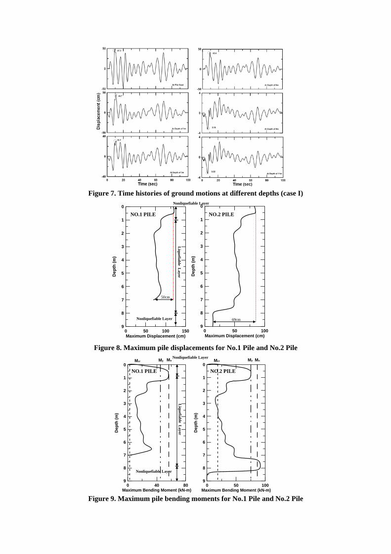
Figure 7. Time histories of ground motions at different depths (case I)
Figure 8. Maximum pile displacements for No.1 Pile and No.2 Pile
Figure 9. Maximum pile bending moments for No.1 Pile and No.2 Pile
0 50 100Maximum Displacement (cm)
0
1
2
3
4
5
6
7
8
9
Dep
th (m
)
69cm
0 50 100 150Maximum Displacement (cm)
0
1
2
3
4
5
6
7
8
9
Dep
th (m
)
NO.1 PILE L
iquefiable Layer
Nonliquefiable Layer
Nonliquefiable Layer
50cm
NO.2 PILE
0 50 100Maximum Bending Moment (kN-m)
0
1
2
3
4
5
6
7
8
9
Dep
th (m
)
Mcr My Mu
0 40 80Maximum Bending Moment (kN-m)
0
1
2
3
4
5
6
7
8
9
Dep
th (m
)
Mcr My Mu
NO.1 PILE
Liquefiable L
ayer
Nonliquefiable Layer
Nonliquefiable Layer
NO.2 PILE
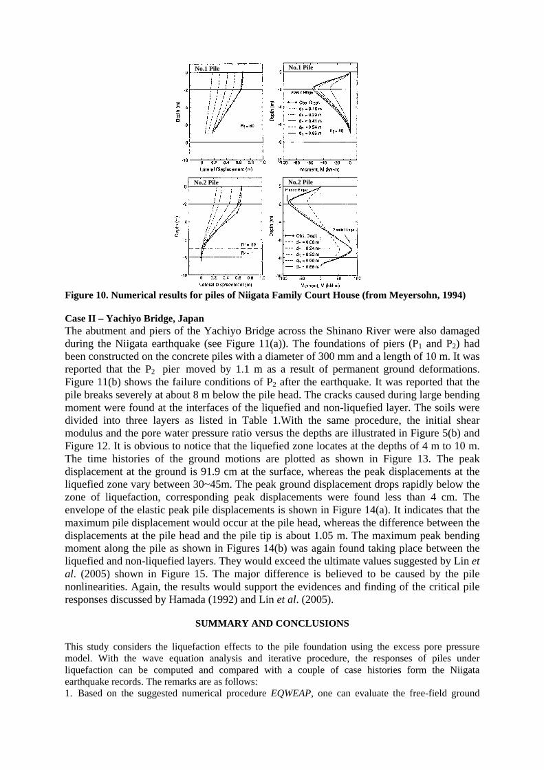
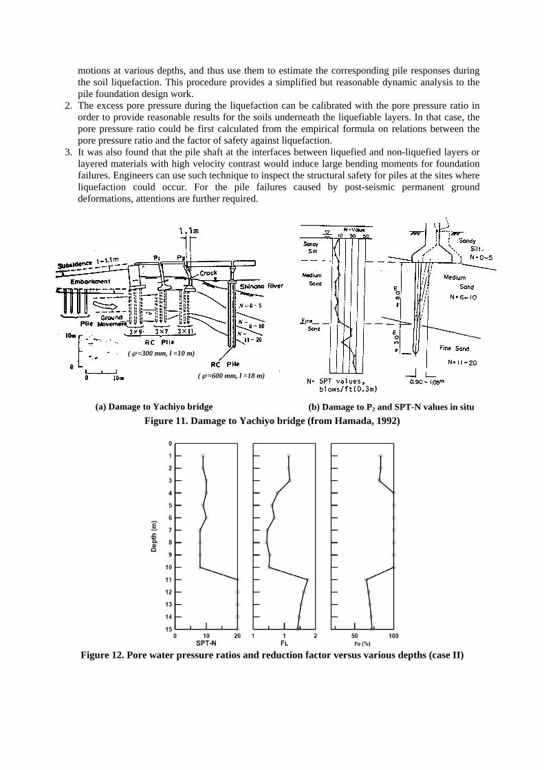
Figure 10. Numerical results for piles of Niigata Family Court House (from Meyersohn, 1994) Case II – Yachiyo Bridge, Japan The abutment and piers of the Yachiyo Bridge across the Shinano River were also damaged during the Niigata earthquake (see Figure 11(a)). The foundations of piers (P1 and P2) had been constructed on the concrete piles with a diameter of 300 mm and a length of 10 m. It was reported that the P2 pier moved by 1.1 m as a result of permanent ground deformations. Figure 11(b) shows the failure conditions of P2 after the earthquake. It was reported that the pile breaks severely at about 8 m below the pile head. The cracks caused during large bending moment were found at the interfaces of the liquefied and non-liquefied layer. The soils were divided into three layers as listed in Table 1.With the same procedure, the initial shear modulus and the pore water pressure ratio versus the depths are illustrated in Figure 5(b) and Figure 12. It is obvious to notice that the liquefied zone locates at the depths of 4 m to 10 m. The time histories of the ground motions are plotted as shown in Figure 13. The peak displacement at the ground is 91.9 cm at the surface, whereas the peak displacements at the liquefied zone vary between 30~45m. The peak ground displacement drops rapidly below the zone of liquefaction, corresponding peak displacements were found less than 4 cm. The envelope of the elastic peak pile displacements is shown in Figure 14(a). It indicates that the maximum pile displacement would occur at the pile head, whereas the difference between the displacements at the pile head and the pile tip is about 1.05 m. The maximum peak bending moment along the pile as shown in Figures 14(b) was again found taking place between the liquefied and non-liquefied layers. They would exceed the ultimate values suggested by Lin et al. (2005) shown in Figure 15. The major difference is believed to be caused by the pile nonlinearities. Again, the results would support the evidences and finding of the critical pile responses discussed by Hamada (1992) and Lin et al. (2005).
SUMMARY AND CONCLUSIONS This study considers the liquefaction effects to the pile foundation using the excess pore pressure model. With the wave equation analysis and iterative procedure, the responses of piles under liquefaction can be computed and compared with a couple of case histories form the Niigata earthquake records. The remarks are as follows: 1. Based on the suggested numerical procedure EQWEAP, one can evaluate the free-field ground
No.2 Pile No.2 Pile
No.1 Pile No.1 Pile
motions at various depths, and thus use them to estimate the corresponding pile responses during the soil liquefaction. This procedure provides a simplified but reasonable dynamic analysis to the pile foundation design work.
2. The excess pore pressure during the liquefaction can be calibrated with the pore pressure ratio in order to provide reasonable results for the soils underneath the liquefiable layers. In that case, the pore pressure ratio could be first calculated from the empirical formula on relations between the pore pressure ratio and the factor of safety against liquefaction.
3. It was also found that the pile shaft at the interfaces between liquefied and non-liquefied layers or layered materials with high velocity contrast would induce large bending moments for foundation failures. Engineers can use such technique to inspect the structural safety for piles at the sites where liquefaction could occur. For the pile failures caused by post-seismic permanent ground deformations, attentions are further required.
Figure 11. Damage to Yachiyo bridge (from Hamada, 1992)
Figure 12. Pore water pressure ratios and reduction factor versus various depths (case II)
(φ=300 mm, l =10 m)
(φ=600 mm, l =18 m)
(a) Damage to Yachiyo bridge (b) Damage to P2 and SPT-N values in situ

Figure 13. The time history of ground motions at different depths (case II)
Figure 14. The envelope of the peak displacements and maximum pile bending moments for P2
Figure 15. Numerical results for piles of Yachiyo Bridge (from Lin et al., 2005)
AKNOWLEDGEMENTS This work is a partial result of the studies through research contrasts NSC95-2221-E-032-043 from National Science Council in ROC. The authors express their sincere gratitude for the supports.
0 40 80 120 160Maximum Bending Moment (kN-m)
0
1
2
3
4
5
6
7
8
9
10
11
12
13
14
Dep
th (m
)
Mcr My Mu
Liquefiable L
ayer N
onliquefiable Layer
Nonliquefiable L
ayer
0 50 100 150Maximum Displacement (cm)
0
1
2
3
4
5
6
7
8
9
10
11
12
13
14
Dep
th (m
)
105 cm
Liquefiable L
ayer N
onliquefiable Layer
Nonliquefiable L
ayer
(a) Peak displacements envelope (b) Maximum bending moments

REFERENCES Arduino, P., Kramer, S.L., Li, P. and Home, J. "Stiffness of Piles in Liquefiable Soils," Procds., ASCE
Conf. on Seismic Performance and Simulation of Pile Foundations in Liquefied and Laterally Spreading Ground, pp. 135-148, 2005 (in U.S.A.).
Boulanger, R.W., Curras, C.J., Kutter, B.L., Wilson, D.W. and Abghari, A. "Seismic Soil-Pile-Structure Interaction Experiments and Analyses," Journal of Geotechnical and Geoenvironmental Engineering, ASCE, Vol. 125, No. 9, pp. 750-759, 1999.
Brandenberg, S.J. and Boulanger, R.W., Kutter, B.L. and Chang, D. "Behavior of Pile Foundation in Laterally Spreading Ground during Centrifuge Tests," Journal of Geotechnical and Geoenvironmental Engineering, ASCE, Vol. 131, No. 11, pp. 1378-1391, 2005.
Chang, D.W., Lee, S.H. and Chin, C.T. "Wave Equation Analyses for Seismic Grouped Pile Responses," Procds., 15th International Conf. on Soil Mechanics and Geotechnical Engineering, pp. 859-862, 2001 (in Istanbul).
Chang, D.W. and Lin, B.S. "Wave Equation Analyses on Seismic Responses of Grouped Piles," Proc. of the 12th Asian Regional Confnference on Soil Mechanics and Geotechnical Engineering, pp. 581-586, 2003 (in Singapore).
Chang, D.W. and Lin, B.S. "EQWEAP~a Simplified Procedure to Analyze Dynamic Pile-Soil Interaction with Soil Liquefaction Concerns," Second Taiwan-Japan Joint Workshop on Geotechnical Hazards from Large Earthquake and Heavy Rainfall, pp. 155-162, 2006 (in Japan).
Finn, W.D.L. and Thavaraj, T. "Practical Problems in the Seismic Analysis of Bridge Pile Foundations," Proc. of the 10th Int. Conf. Computer Methods and Advances in Geomechanics, pp. 1011-1018, 2001 (in U.S.A.).
Finn, W.D.L., Lee, K.W., and Martin, G.R. " An Effective Stress Model for Liquefaction," Journal of the Geotechnical Engineering Division, ASCE, 103(SM7), pp. 657-692, 1977.
Hamada M. "Large Ground Deformations and Their Effects on Lifelines:1964 Niigata Earthquake," in Case Studies of Liquefaction and Lifeline Performance During Past Earthquakes, 1, Japanese Case Studies, Technical Report NCEER-92-0001, 1992 (NCEER, Buffalo, NY, USA.).
Liyanapathirana, P.S. and Poulos, H.G. "Pseudostatic Approach for Seismic Analysis of Piles in Liquefying Soil," Journal of Geotechnical and Geoenvironmental Engineering, Vol. 131, Issue 12, pp. 1480-1487, 2005.
Lin, S.S., Tseng, Y.J., Chiang, C.C. and Hung, C.L. "Damage of Piles Caused by Laterally Spreading – Back Study of Three Cases," Procds., ASCE Conf. on Seismic Performance and Simulation of Pile Foundations in Liquefied and Laterally Spreading Ground, pp. 121-133, 2005 (in U.S.A.).
Ishihara, K., and Cubrinovski, M. "Case Studies on Pile Foundations undergoing Lateral Spreading in Liquefied Deposits," Procds., 5th Int. Conf. on Case Histories in Geotechnical Engineering, CDRom, 2005 (in New York).
Martin, G.R., Finn, W.D.L., and Seed, H.B. "Fundamentals of Liquefaction under Cyclic Loading," Journal of the Geotechnical Engineering Division, ASCE, 101(GT5), pp. 423-438, 1975.
Meyersohn, W.D. "Pile Response to Liquefaction-induced Lateral Spread," Doctor’s Dissertation, University of Cornell, 1994 (in U.S.A.).
Seed, H.B., and Idriss, I.M. "Soil Moduli and Damping Factors for Dynamic Response Analysis," Report No. EERC 75-29, Earthquake Engineering Research Center, 1970 (University of California, Berkeley, California).
Tokimatsu K. and Yoshimi Y. "Empirical Correlation of Soil Liquefaction Based on SPT N-Value and Fines Content,"Soil and Foundations, JSSMFE, 23(4), pp. 56-74, 1983.
Wilson, D. W., Boulanger, R. W. and Kutter, B.L. "Observed Seismic Lateral Resistance of Liquefying Sand," Journal of Geotechnical and Geoenvironmental Engineering, ASCE, Vol. 126, No. 10, pp. 898-906, 2000.