Embed Size (px)
Citation preview

Click here to return to Session Directory
DYNAMIC POSITIONING CONFERENCE
October 12-13, 1999
DESIGN SESSION
Marine Riser Management System for Deep-Water Drilling
Per Osen and Morten Høklie
Seaflex
Dynamic Positioning CommitteePMarine Technology Society
d

Click here to return to Session Directory
Per Osen and Morten Hoklie
DESIGN Marine Riser Management System for Deep-Water Drilling
DP Conference Houston October 12-13, 1999 2
1. INTRODUCTION
SeaFlex' development of a Riser Management System (RMS) originated in 1992. The idea of a RMS evolved while working on projects checking the structural integrity and establishing operational limitations for completion/workover (C/WO) risers. The risers were to be operated all-season in the harsh environments offshore Norway. It soon became evident that the structural design was incompatible with the environmental and operational criteria. However, our analyses clearly indicated that by careful vessel positioning, structural safety could be maintained even under very severe weather conditions. To make a long story short, Statoil funded part of the development work, first with focus on C/WO riser, later with focus on marine drilling risers. SeaFlex was awarded the contract for the supply of system No. 1 early 1996. (Ref. 3). Now, altogether three systems have been supplied, and No. 4 has recently been ordered. See Table 1.
Table 1 Riser Management Systems supplied or in progress
System No.
Supplied Year
Customer Vessel Comment
1 1996 Statoil Transocean Prospect
For completion/workover riser. Reported in OTC8797.
2 1998 Saipem Scarabeo 5 Operated in 1350 m water at Gjallar Field, N. Atlantic
3 1999 Stena Drilling
Stena Tay First ops. scheduled for Sept. 1999, offshore Trinidad
4 2000 Saipem Saipem 10000 Project kick-off Sept. 1999 The first two systems were developed in close co-operation with the Norwegian company Robit Technology a.s, who was responsible for supplying all computer and sensor hardware, with SeaFlex responsible for system design and software. During the Scarabeo 5 project, the RMS controller was closely linked to the Kongsberg Simrad DP system. This catalysed the establishment of a co-operation agreement between Kongsberg Simrad and SeaFlex. Under this agreement, a tailor-made RMS was recently supplied to semi-submersible Stena Tay owned by Stena Drilling Ltd. Eventually, in June'99, Kongsberg Simrad / SeaFlex was awarded the contract for the supply of a comprehensive RMS for the new drillship Saipem 10000. The concept of monitoring the drilling riser, and using the data as reference for positioning a drilling vessel is not new. A number of systems have been developed and taken into service. General references to some relevant papers and publications can be found at the end of this paper.

Click here to return to Session Directory
Per Osen and Morten Hoklie
DESIGN Marine Riser Management System for Deep-Water Drilling
DP Conference Houston October 12-13, 1999 3
2. SYSTEM OBJECTIVES
The primary objectives of the RMS are to maximise operability and maintain safety of marine drilling riser operations. The following "undesirable event scenarios" are considered: • High internal wear of the riser and flex-joints, due to the rotating drill-string which could
eventually lead to riser penetration and loss of well control • Bending and fatigue of the through-riser equipment, near the flex-joints • Bending and shear in the wellhead or LMRP connectors. High bottom tension in deep waters
leads to high bending moments in connectors even at small flex-joint angles and may also obstruct connector release
• Stroke-in or stroke-out of the slip-joint or riser tensioners, which could severely damage the riser system and/or the wellhead
• Loss of tension in the riser, excessive flex-joint angles and riser buckling • Excessive tension in the riser with excessive wear of tensioners and riser • Loss of station (drift-off) with riser connected To avoid and/or control such events, the following functions have been implemented in the RMS: • The top and bottom riser flex-joint angles are monitored. Alarms are triggered when flex-joint
angles exceed given limits, e.g. defined by acceptable wear or equipment stress. Alarms are tri-state, green/yellow/red.
• The flex-joint angles are input to the RMS vessel position optimisation module, which calculates a recommended DP-setpoint (vessel relative or Earth relative), and the safe area around it. As long as the vessel rotary table is kept inside the safe area, the flex-joint angles will be within the limits set by operator. The program provides this information for three operating modes: Drilling, Non-Drilling and Prepare-for-Disconnect.
• By use of hydro-acoustic inclinometer transponders, riser mid-span inclinations can be monitored at up to six different levels. These data are input to the RMS mathematical riser model, to determine riser shape and a current velocity profile estimate.
• Monitoring of the stroke of riser slip-joint and tensioners. This includes statistical analysis of the stroke history, to determine when there is a risk of a full stroke in/out. Alarm indicators are lit if there is a risk of a stroke-out or stroke-in.
• Monitoring of the tensioner pull forces, and calculation of the total riser top pull. Applying the mathematical riser model, the tension distribution in the riser all the way down to the wellhead is calculated. Alarm indicators are lit if top or bottom tension violate the high/low limits specified by API RP 16Q for marine drilling risers.
• A Time-To-Go simulation function is implemented. This is a computer simulation of riser responses during a vessel drift-off. The function is based on the Kongsberg Simrad vessel
Click here to return to Session Directory
Per Osen and Morten Hoklie
DESIGN Marine Riser Management System for Deep-Water Drilling
DP Conference Houston October 12-13, 1999 4
Motion Prediction module, in combination with the RMS mathematical riser model. The boundary conditions are based on the on-line measurements. At pre-set intervals, this simulation will execute automatically, and estimate the time available for a safe emergency disconnect, should a vessel drift-off occur.

Click here to return to Session Directory
Per Osen and Morten Hoklie
DESIGN Marine Riser Management System for Deep-Water Drilling
DP Conference Houston October 12-13, 1999 5
3. SYSTEM CONFIGURATION
The Stena Tay project is the first RMS supply totally integrated with the Kongsberg Simrad DP System (SDP). The system configuration is shown in
Figure 1. The RMS software runs on a dedicated Operator Station, the RMS-OS. This is of similar design as the DP-OS, and fully integrated in the DP Network. All sensor data are acquired via the network, and essential RMS output data (e.g. recommended vessel set point and safe areas) can be displayed on the DP-OS.
DUAL ETHERNET
RMS - Operator Station(Control Room)
DP - Operator Station(Control Room)
DP Controller(Radio Room)
RMS – Slave Monitor(Drillers Cabin)
Thruster
GPSs
Motion Reference Units
Gyro Compasses
Taut Wire
Wind Sensors
HPRs
Riser TensionerSystem
BOP ControlSystem
Process Station(PS) 10
Thruster
Thruster Controllers
Figure 1 System Configuration
The input data to the RMS can be divided in classes as follows:

Click here to return to Session Directory
Per Osen and Morten Hoklie
DESIGN Marine Riser Management System for Deep-Water Drilling
DP Conference Houston October 12-13, 1999 6
• On-line sensor data • Manual input set-up data • Manual over-ride of sensor signals • System configuration settings All the required sensor signals are received via the Kongsberg Simrad DP network. In certain cases (e.g. in case of dubious or absent sensor signals), it is possible to replace a sensor signal by a user-defined value taken from other sources. Sensor data from the following sources are transferred to the RMS via the SDP network: • The BOP Control System; BOP and lower riser inclinations and mud pressure • The Simrad Dynamic Positioning System; Vessel motions, heading and position • The Riser Tensioner Control System; Top tension and stroke • Upper riser inclinometer; Upper riser inclinations Sensor data are provided in the form of telegrams that are updated typically once per second. A typical sensor configuration is shown in Figure 2.
Figure 2 Typical sensor configuration

Click here to return to Session Directory
Per Osen and Morten Hoklie
DESIGN Marine Riser Management System for Deep-Water Drilling
DP Conference Houston October 12-13, 1999 7
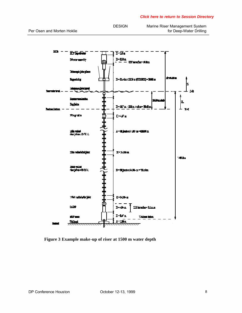
Information derived by the RMS are distributed in the SDP network and displayed at the DP-OS. Typically this information consist of optimum position and safe areas together with alarm status and the “Time to Go” estimate. The system will be configured for operation onboard each particular vessel. The initial configuration settings include the riser data, vessel geometry, tensioner geometry, and other vessel constants, which shall not require user intervention. The RMS requires a mathematical model of the riser and a new model has to be generated for each particular well. To facilitate this modelling, all necessary data for each riser joint such as geometry, weight and buoyancy properties as well as hydrodynamic coefficients are stored during the initial configuration. The operator interactively selects type and number of joints and stacks the joints together in the desired sequence. RMS calculates the accumulated length and weight of the riser together with the minimum required top tension according the API recommendations. Figure 3 describes a typical riser make-up plan. The mathematical riser representation in RMS is based on a tensioned cable with variable tension and weight properties. This is normally an adequate representation of tensioned risers where the influence of the bending stiffness is small. The operational limitations that applies for the actual modes of operations are entered by the operator. The operational limitations are typically defined for three levels of severity, i.e. normal (green), alert (yellow) and emergency (red). These limits may be defined for the desired number of monitored and derived parameters.
Click here to return to Session Directory
Per Osen and Morten Hoklie
DESIGN Marine Riser Management System for Deep-Water Drilling
DP Conference Houston October 12-13, 1999 8
Figure 3 Example make-up of riser at 1500 m water depth

Click here to return to Session Directory
Per Osen and Morten Hoklie
DESIGN Marine Riser Management System for Deep-Water Drilling
DP Conference Houston October 12-13, 1999 9
4. OPTIMUM POSITION
The actual vessel position relative to the recommended optimum position and safe areas are displayed by the RMS in terms of an “overhead view” graph of the rig, with “safe circles”, recommended position and the well head position. There are generally two safe circular areas, and the vessel’s rotary table should be located inside both circles. The typical main display on the RMS-OS are shown in Figure 4. The thick-line blue (small) circle encompasses the vessel positions where the lower flex-joint angle will be acceptable. The thin-line blue (large) circle encompasses the vessel positions where the upper flex-joint angle will be acceptable.
Figure 4 Main display on the RMS-OS
Further, the vessel graphical display provides the following symbols: • A North-Up overhead view of the vessel; Rotary indicated by a small circle symbol. • Recommended optimum vessel position indicated by an open square. • BOP wellhead position, indicated by an irregular pentagon.

Click here to return to Session Directory
Per Osen and Morten Hoklie
DESIGN Marine Riser Management System for Deep-Water Drilling
DP Conference Houston October 12-13, 1999 10
The “safe circle” radiuses depend on the riser tension distribution and the specified Yellow ala rm limits for the flex-joint angles that have been defined for the selected operating mode. There may typically be three operational mode options: • DRILLING • NON-DRILLING • DISCONNECT In Drilling Mode, the program calculates the position where the angles in both flex-joints are such that utilisation of the permissible angle (yellow limit) is equal for both the top and bottom flex-joints, and such that the angles are as small as possible. Non-Drilling Mode is similar, except that other, user-defined operational are applied. The non-drilling mode can be utilised for e.g. optimised deployment of long and rigid tools, e.g. running of tubing hanger with landing string. In such cases, it is essential to keep flex-joints as straight as possible during passage of the tools. The Disconnect Mode is selected for optimising the rig position prior to a planned disconnect of the riser from the wellhead. In this mode, the essential issue is to keep the lowermost riser joint vertical. This will minimise horizontal shear in the BOP stack. This is assumed the most favourable condition when the BOP or LMRP connector is to be released. Typical information that are displayed in the main display in Figure 4 are: • The vessel graphical display • The selected operational mode (e.g., Drilling mode) • Estimated vessel position, EVP (received from SDP) • Vessel Repos-vector, RPV (distance and direction to move the vessel to minimise flex-joint
angles) • Recommended set-point (EVP + RPV) • Vessel Offset from wellhead position (EVP – WHP) • Slip-joint stroke (m) • Measured or operator specified mud density • Upper flex-joint (UFJ) angle • Lower flex-joint (LFJ) angle • Riser top tension • Bottom (LFJ) tension (Top tension minus submerged weight of riser & mud) • Vessel heading • Time-to-Go i.e. available time for a safe emergency disconnect, in case of drift-off under the
actual environmental conditions, as explained in next section. • Alarm indicators for flex-joint angles, top tension and stroke. • Data Communication status.

Click here to return to Session Directory
Per Osen and Morten Hoklie
DESIGN Marine Riser Management System for Deep-Water Drilling
DP Conference Houston October 12-13, 1999 11
In addition to the main display, there are a number of displays where details of the monitored data can be examined in more details both graphically and numerically.

Click here to return to Session Directory
Per Osen and Morten Hoklie
DESIGN Marine Riser Management System for Deep-Water Drilling
DP Conference Houston October 12-13, 1999 12
5. RISER SHAPE AND CURRENT PROFILE
A rough riser shape and current velocity profile estimate can be estimated using the measured flex-joint angles, vessel offset and top tension distribution. In order to obtain better estimates, additional inclinometer transponders may be added along the riser span. With a proper riser shape estimate, areas with high drill string contact forces and potential wear can be identified based on the riser curvature. The method for providing these estimates is based on a polynomial fit of the unknown current force profile using the above mentioned measurements. The order of the current force polynomial can be selected based on the available number of riser inclination measurements. Effects of wave motions are filtered out and the riser shape estimate reflects the riser response due to the static current forces. A typical display of the riser shape projected in two vertical planes and in a birds view are presented in Figure 5. Similarly, the current velocity profile estimate is displayed in two vertical projections.
Figure 5 Riser Shape display.

Click here to return to Session Directory
Per Osen and Morten Hoklie
DESIGN Marine Riser Management System for Deep-Water Drilling
DP Conference Houston October 12-13, 1999 13
6. TIME-TO-GO
The Time to Go function estimates the available time to perform a disconnect in case of a vessel drift-off. The DP system determines the most critical single failure with respect to a possible drift-off and utilises the DP Motion Prediction Module to predict the vessel drift-off paths. Based on these drift-off paths, the RMS predicts the corresponding riser responses and estimates the minimum available time until critical riser angles, well head forces or stroke limits will be exceeded. The Time to Go estimate reflects the actual environmental conditions and is updated on a regular basis. For calculation of the riser responses the actual current profile will be needed. A current profile estimate can be obtained as described in the previous section or data from current measurements can be interfaced to the RMS and used. The Motion Prediction view may typically be as shown in Figure 6.
Figure 6 Motion prediction drift off path
Click here to return to Session Directory
Per Osen and Morten Hoklie
DESIGN Marine Riser Management System for Deep-Water Drilling
DP Conference Houston October 12-13, 1999 14
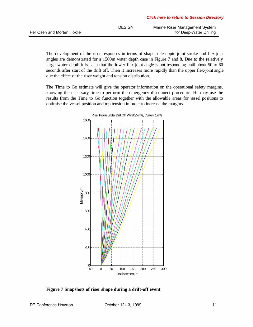
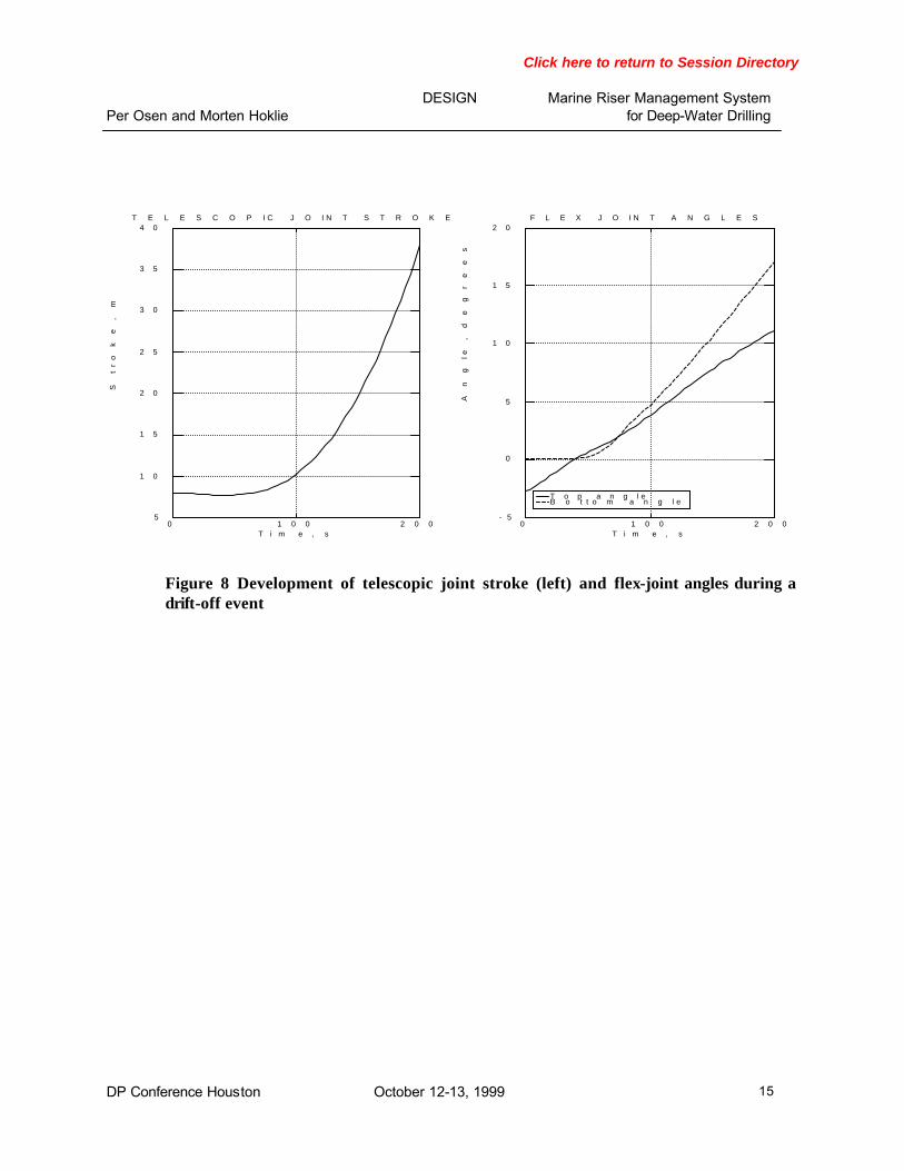
The development of the riser responses in terms of shape, telescopic joint stroke and flex-joint angles are demonstrated for a 1500m water depth case in Figure 7 and 8. Due to the relatively large water depth it is seen that the lower flex-joint angle is not responding until about 50 to 60 seconds after start of the drift off. Then it increases more rapidly than the upper flex-joint angle due the effect of the riser weight and tension distribution. The Time to Go estimate will give the operator information on the operational safety margins, knowing the necessary time to perform the emergency disconnect procedure. He may use the results from the Time to Go function together with the allowable areas for vessel positions to optimise the vessel position and top tension in order to increase the margins.
Figure 7 Snapshots of riser shape during a drift-off event
-50 0 50 100 150 200 250 3000
200
400
600
800
1000
1200
1400
1600Riser Profile under Drift Off, Wind 25 m/s, Current 1 m/s
Displacement, m
Elev
ation
, m
Click here to return to Session Directory
Per Osen and Morten Hoklie
DESIGN Marine Riser Management System for Deep-Water Drilling
DP Conference Houston October 12-13, 1999 15
Figure 8 Development of telescopic joint stroke (left) and flex-joint angles during a drift-off event
T o p a n g l e B o t t o m a n g l e
0 1 0 0 2 0 0- 5
0
5
1 0
1 5
2 0F L E X J O I N T A N G L E S
T i m e , s
An
gle
,
de
gr
ee
s
0 1 0 0 2 0 05
1 0
1 5
2 0
2 5
3 0
3 5
4 0T E L E S C O P I C J O I N T S T R O K E
T i m e , s
St
ro
ke
,
m

Click here to return to Session Directory
Per Osen and Morten Hoklie
DESIGN Marine Riser Management System for Deep-Water Drilling
DP Conference Houston October 12-13, 1999 16
7. REFERENCES
1. API RP 16Q “Recommended Practice for Design, Selection, Operation and Maintenance
of Marine Drilling Riser Systems.”
2. Quenton W. Dean, “A Riser Angle Positioning System (RAPS)”, OTC 3755 (1980)
3. Tore Geir Wernø, Kalle Strømsem, Birte Johannessen, and Per Osen: "Instrumented Monitoring of Workover Risers", OTC8797 (1998).
4. Thomas R. Stockton, "A Real-Time Riser Management System for DP Drilling Vessels", MTS Dynamic Positioning Conference, 1998.