Embed Size (px)
Citation preview

Chih-Hsing LiuSingapore Institute of Manufacturing Technology,
Singapore 638075
e-mail: [email protected]
Kok-Meng Lee1
The George W. Woodruff School of
Mechanical Engineering,
Georgia Institute of Technology,
Atlanta, GA 30332 –0405
e-mail: [email protected]
Dynamic Modeling of DampingEffects in Highly DampedCompliant Fingers forApplications Involving ContactsIn many industries, it is often required to transfer objects using compliant fingers capableof accommodating a limited range of object shapes/sizes without causing damage to theproducts being handled. This paper presents a coupled computational and experimentalmethod in time domain to characterize the damping coefficient of a continuum structure,particularly, its applications for analyzing the damping effect of a highly damped compli-ant finger on contact-induced forces and stresses. With the aid of Rayleigh damping andexplicit dynamic finite element analysis (FEA), this method relaxes several limitations ofcommonly used damping identification methods (such as log-decrement and half-powermethods) that are valid for systems with an oscillatory response and generally estimatethe damping ratio for a lumped parameter model. This damping identification methodimplemented using off-the-shelf commercial FEA packages has been validated by com-paring results against published data; both oscillatory and nonoscillatory responses areconsidered. Along with a detailed discussion on practical issues commonly encounteredin explicit dynamic FEA for damping identification, the effects of damping coefficients oncontact between a rotating compliant finger and an elliptical object has been numericallyinvestigated and experimentally validated. The findings offer a better understanding forimproving grasper designs for applications where joint-less compliant fingers are advan-tageous. [DOI: 10.1115/1.4005270]
Keywords: damping, flexible mechanism, rotating finger, compliant finger, finite element,multibody dynamics
1 Introduction
Compliant mechanisms that transfer force, motion, and energythrough elastic deformations offer several advantages in food-product handling applications where designs must accommodate alimited range of object sizes and shapes. Most existing dynamicanalyses of compliant multibody systems are based on quasi-staticlumped parameter models without considering the effects ofdamping. However, damping effects play an important role in me-chanical handling of natural and/or live products at high produc-tion speed; therefore, it is desirable to have a good understandingof the damping effect on the contact-induced forces and stressesin order to facilitate the design of a flexible multibody dynamicsystem.
This paper is motivated by the need to analyze dynamic per-formances of compliant fingers in order to reduce the number ofdesign configurations and live broilers (meat chickens) needed indeveloping an automated live-bird transfer system [1] for thepoultry meat processing industry. A fundamental task is thedesign and control of mechanical “hands” with rotating compliantfingers, which offer several advantages including light weight, no.relative moving parts (hence, less expensive to manufacture), andmost importantly, the flexibility to accommodate a limited rangeof sizes/shapes and natural reactions without causing damage toproducts. To overcome limitations of lumped parameter modelssuch as pseudo-rigid-body models [2,3] that treat flexible mem-bers as rigid links with torsional pin-joints, Lee et al. [4] per-formed a parametric study using 2D finite element analysis (FEA)
on contact forces acting on an object. Several other analyticalmodels [5,6] have also been developed to predict the contact forceand deflected shape of compliant fingers. These studies generallymodel the finger as a 2D beam and analyze the finger dynamicsquasi-statically without considering damping effects.
Damping, which dissipates energy and causes vibration todecay with time, is often characterized by a damping ratio(defined as the ratio of actual to critical viscous damping). Toobtain the damping parameters, time, or frequency domain experi-ments are usually required. In time domain, damping ratios aredetermined from logarithmic decrements; for examples, freevibration of steel poles and tubular towers measured by acceler-ometers [7]; and impulse response of a wire cable [8] capturedusing a high-speed digital camera. Damping ratios can also be cal-culated from the half-power bandwidth of a measured frequencyresponse; for example, the frequency response of a gearbox meas-ured with a laser vibrometer in Ref. [9]. These damping identifica-tion methods (based on log-decrement or half-power bandwidth)that estimate the damping ratios for lumped parameter models areonly valid for lightly damped structures exhibiting overshoots.Rayleigh damping (also known as proportional damping) is oftenused in mathematical models for simulating the dynamic responseof a structure (for examples, Refs. [8,10]). Expressed as a linearcombination of terms proportional to the stiffness and mass of thestructure, Rayleigh damping avoids the need to form a dampingmatrix based on the physical properties of the real structure in nu-merical analyses. To better understand the damping effect on thereaction forces and stresses due to contact, we investigate the useof three-dimensional (3D) explicit dynamic FEA methods formodeling the dynamics of a flexible multibody system with largedeformations and contact nonlinearities. The remainder of this pa-per offers the following:
1Corresponding author.Contributed by the Dynamic Systems Division of ASME for publication in the
JOURNAL OF DYNAMIC SYSTEMS, MEASUREMENT AND CONTROL. Manuscript received July2, 2010; final manuscript received July 31, 2011; published online December 2,2011. Assoc. Editor: Luis Alvarez.
Journal of Dynamic Systems, Measurement, and Control JANUARY 2012, Vol. 134 / 011005-1Copyright VC 2012 by ASME
Downloaded 19 Dec 2011 to 222.205.26.123. Redistribution subject to ASME license or copyright; see http://www.asme.org/terms/Terms_Use.cfm

(1) A coupled computational and experimental damping identi-fication (CCEDI) method, which models the damping of ahighly damped flexible member in the time domain for nu-merical analysis, is presented. This method relaxes severallimitations on log-decrement or half-power methods thatare only applicable for systems with an oscillatory responseand generally estimate the damping ratio for a lumped pa-rameter model. This CCEDI method with Rayleigh damp-ing is able to obtain the damping coefficient of a continuumstructure. As will be shown, Rayleigh damping reduces to asingle mass proportional term for low-frequency applica-tions where the stiffness proportional term is insignificant.Based on this approach, the critical damping coefficient canbe obtained numerically and the damping coefficient of ahighly damped structure can be estimated with the aid ofexperimental data.
(2) The CCEDI method can be implemented using off-the-shelfgeneral-purpose numerical packages. In this paper, the nu-merical packages ANSYS, LS-DYNA, and LS-PREPOST are usedfor preprocessing, solving, and postprocessing, respec-tively, where the nodal coordinate and element data arenumerically programmed by the ANSYS Parametric DesignLanguage (APDL) and output as a text file; and the discretefinite element (FE) equations of motion, along with thedefined boundary conditions and contact algorithm, aresolved using LS-DYNA. The CCEDI method has been vali-dated by comparing results against published data. Under-damped and over-damped cases are both discussed.
(3) Practical issues encountered in dynamic FEA based onexplicit time-integration methods are discussed. Comparedto implicit methods which are stable for linear and manynonlinear problems, explicit methods are computationallyless expensive since no matrix inversion is required in eachtime-step. However, explicit methods are only stable whenthe time-step is smaller than a critical size known as theCourant–Friedrichs–Levy (CFL) condition [11,12]; andthus, the time-step size is a compromise between numericalstability and computation time.
(4) The effect of different damping coefficients on the contactbetween a rotating finger and an elliptical object is numeri-cally investigated and discussed. The findings provide ameans for improving grasper designs and for applicationswhere joint-less compliant fingers are advantageous.
2 FEA-based Damping Model Consideration
The discrete equations of motion for FEA can be derived fromthe work balance contributed by the external load, inertial effect,viscosity, and strain energy. The computational model for the sys-tem is outlined in Appendix A
½M�f €Xg þ ½C�f _Xg þ ½K�fXg ¼ fFg (1)
where {X} is the global nodal degree of freedom (DOF); {F} isthe load vector; and [M], [C], and [K] are the global mass, damp-ing, and stiffness matrices, respectively. ANSYS and LS-DYNA (witha built-in penalty method to handle deformable contacts) are usedto create the discrete domain {X}, and solve Eq. (1) using anexplicit FEA method, respectively. In this paper, Rayleigh (pro-portional) damping is assumed
½C� ¼ a½M� þ b½K� (2)
where the mass and stiffness matrices, [M] and [K] defined inEq. (1), can be formulated once the element types are defined.The relative effect of the coefficients a and b on the effectivedamping ratio f can be illustrated with a classical single-DOF sys-tem (mass m and spring k with damper written as c¼ amþbk),where the natural frequency xn and damping ratio f are written as
x2n ¼
k
m(3a)
f ¼ c
ccr¼ 1
2
axnþ bxn
� �(3b)
Based on Eq. (3b), the proportional damping effect is illustrated inFig. 1 showing that the mass proportional damping term heavilydamps the lowest modes and dominates in low-frequency applica-tions. The opposite effect can be observed for the stiffness propor-tional damping term which damps the modes at high frequencies.The effect can be illustrated numerically with the followingexample:
2.1 Numerical Example. Considering the frequency rangefrom x1 to x2 (with corresponding damping ratios f1 and f2), themass and stiffness proportional coefficients a and b can be solvedfrom the simultaneous equations from Eq. (3b)
a ¼ 2x1x2
f1x2 � f2x1
x22 � x2
1
(4a)
b ¼ 2f2x2 � f1x1
x22 � x2
1
(4b)
As an illustration, consider x1 ¼ 2pð10Þ rad/s, x2 ¼ 2pð20Þ rad/s, and f1¼ f2¼ 0.1, thus a/b¼ 8.38� 103 s�2. The above impliesthat the stiffness proportional b term is insignificant for structuresin the low-frequency modes.
For low-frequency applications, the coefficient a can be deter-mined using a coupled computational and experimental dampingidentification (CCEDI) method as illustrated in Fig. 2. This proce-dure combines explicit dynamic FEA, mass proportional dampingassumption, and traditional damping identification from oscilla-tory response data to determine a. For an over-damped structure,the procedure numerically searches for the damping coefficient bycomparing the solution to Eq. (1) based on an initial a againstexperimentally measured (impulse response) data until a match isfound. For an under-damped case, the damping coefficient is sim-ply the product of acr and f; the latter can be experimentallyobtained using traditional methods, and thus, the proceduresearches for the critical mass proportional coefficient acr betweenoscillation and nonoscillation responses by numerically solvingEq. (1). The advantages of this damping identification techniqueare its capability to analyze highly damped continuum structuresand obtain the damping coefficients for FEA.
2.2 Illustrative Example: Lightly Damped CompliantBeam with Tip Mass. The free vibration of a compliant cantilev-ered steel rod (0.4 m length, 0.6 mm diameter, and 0.9 g mass)with a tip mass (0.015 g) at its free-end is simulated to illustratethe damping identification, where the tip response data (experi-mentally measured by a high-speed camera) are available given in
Fig. 1 Frequency effect of proportional damping on dampingratio
011005-2 / Vol. 134, JANUARY 2012 Transactions of the ASME
Downloaded 19 Dec 2011 to 222.205.26.123. Redistribution subject to ASME license or copyright; see http://www.asme.org/terms/Terms_Use.cfm

Ref. [13] for validation. From the published experimentalresponse, the damping ratio f and natural frequency xn. are foundto be 0.0055 and 16.33 rad/s, respectively. Although the single-DOF lumped parameter model has an advantage of offering thedynamic behavior of the end-point by simply treating the systemas a “black box,” it cannot be used to calculate any contact andstress-strain relation along the beam.
Since the compliant beam vibrates at its 1st mode, the stiffnessproportional damping term is neglected. The critical mass propor-tional coefficient acr is found using the CCEDI procedure. Meshedin ANSYS (with the elements defined in Appendix B), the tipresponse of the steel compliant beam (density q¼ 7957 kg/m3 andYoung’s modulus E¼ 209 GPa) to an impulse loading (0.003 N.for 0.2 s) is simulated by solving Eq. (1) using LS-DYNA. With thecompliant beam and tip mass modeled using the BEAM161element (100 elements and 101 nodes) and MASS166 element(1 element and 1 node) in ANSYS, respectively, the impulseresponse of the tip for a specified a can be computed. BEAM161and MASS166 in ANSYS correspond to Beam Element 1 and MassElement 2 for element transformation to LS-DYNA. Using the log-decrement method to analyze the decaying amplitudes in the itera-tive search, the critical damping coefficient was found to beacr¼ 30 s�1. Thus, a¼ acrf¼ 0.165 s�1, which can be used indynamic FEA. Figure 3 shows the impulse responses computedwith the initial-guessed and critical damping coefficients. TheFEA simulated tip response is compared against published experi-mental results in Fig. 4, which shows excellent agreement.
3 Results and Discussion
We discuss the effects of key design parameters on the dampingof a continuum structure and relevant implementation issues inthe context of a compliant finger (Fig. 5(a)) commonly used inlive broiler handling and processing applications [1,4], wherecontact-induced forces and stresses exerted by rotating fingers onan object are of concern. Detailed in Fig. 5(a), the compliant fin-ger consists of evenly spaced elliptical ribs along with the rein-
forced structure making up of a thin horizontal plate, a cone, anda rectangular section tapering from the fixed circular end (of17.5 mm radius). The finger is designed to bend easily in the XZplane but relatively rigid in other planes. Figure 5(b) shows thesetup for this study, where the tested rubber finger (modelWK52H manufactured by the Waukesha Rubber Company) isclamped at one end and an impulse load is applied at the otherend. A cylindrical (4 mm-radius and 1.65 mm-thick) permanentmagnet is embedded in the fingertip such that the tip displace-ments can be determined from the magnetic field measured by a(Banner S18MB) magnetic sensor.
The following discusses the results of four specific studies;namely, (1) effects of geometric complexity on FEA computationfor damping identification; (2) effectiveness of the CCEDImethod; (3) method validation against previously published ex-perimental data; and (4) effects of damping on reaction forces/stresses.
3.1 Numerical Investigation of the Effect of GeometricalModels on FEA Computation for the Damping Coefficients. TheCCEDI method for determining the damping coefficient, thoughstraight-forward, is computationally time-consuming. Explicittime-integration that determines the next time-step unknowns interms of previously computed quantities is used in order to avoidinverting stiffness matrix in each time-step and thus reduce
Fig. 2 Coupled computational and experimental damping identification (CCEDI) method
Fig. 3 Impulse response with initial guessed and criticaldamping coefficients (acr 5 30 s21, f5 0.0055)
Fig. 4 Comparison of simulation and published experimentaldata (a 5 acrf 5 0.165 s21)
Fig. 5 Setup for damping identification of the compliant finger
Journal of Dynamic Systems, Measurement, and Control JANUARY 2012, Vol. 134 / 011005-3
Downloaded 19 Dec 2011 to 222.205.26.123. Redistribution subject to ASME license or copyright; see http://www.asme.org/terms/Terms_Use.cfm

computational time. Although computationally efficient, the time-step Dt of explicit FEA must satisfy the CFL condition (thatdepends on element types/shapes as well as material properties[11]) to ensure numerical stability [12,14].
To study the effect of geometry and element types on the com-putational time, three simplified FE models (SM-A, B, and C)against the detailed model (DM) are compared in Table 1 wherefor simplicity the acronyms “hexa” and “tetra” refer to three-dimensional 8-node hexagonal and 10-node tetrahedral elements,respectively. The description of hexagonal and tetrahedral ele-ments can be found in Appendix B. All three simplified modelshave the same constant elliptical cross-section (major and minorradii of 12 mm and 8.45 mm, respectively) throughout the lengthbut are meshed with different element sizes and/or shapes. In Ta-ble 1, the equivalent stiffness is computed from the force-displacement relationship at the free-end using the nonlinear staticFEA by ANSYS, where two known loads (1 N and 2 N) were used todetermine the average equivalent stiffness.
For stability consideration, the numerical time-step must besmaller than the critical time-step which is the smallest value inthe global analysis domain (and thus, it is desirable to have a uni-form mesh in explicit FEA):
Dtnum ¼ a�min Dt1;Dt2;…Dtnf g (5)
where a is the scale factor between 0 and 1, and defined as 0.9 inthis study. The critical time-step calculations for tetrahedral andhexahedral solid elements can be found in Ref. [11], and are givenhere for completeness
Dt ¼ Le
QþffiffiffiffiffiffiffiffiffiffiffiffiffiffiffiffiQ2 þ c2
w
p� � where cw ¼
ffiffiffiffiffiffiffiffiffiffiffiffiffiffiffiffiffiffiffiffiffiffiffiffiffiffiffiffiffiffiffiffiffiffiE 1� tð Þ
q 1þ tð Þ 1� 2tð Þ
s;
Q ¼C1cw þ C0Le _ej;j _e < 0
0; _e � 0
�; and
Le ¼Ve=Aemax; hexahedral
minimum altitude; tetrahedral
�(6)
In Eq. (6), Q is a function of the bulk viscosity coefficients C0 andC1; _e is the strain rate; Ve is the volume of the element; and Aemax
is the area for the largest side of the element. The effects of criti-cal time-steps on the computation time are illustrated in the lastcolumn of Table 1, where “# of steps to 0.2 s” intuitively indicatesthe number of numerical steps needed for computing a 0.2-s prob-lem; and the step ratio of a FE model is its “# of steps to 0.2 s”divided by that of the SM-A. In addition, the computation time ineach step depends on the matrix size (3 n� 3 n) where n is thenumber of nodes in the 3rd column of Table 1.
Solved from Eq. (1) with the low-frequency assumption (b¼ 0)and a specified a¼ 180 s�1, the simulated tip responses and maxi-mum equivalent stresses of a 4.5-in. finger to an impulse load arecompared in Fig. 6. Some observations can be made from Table 1and Fig. 6:
(1) All three simplified models yield similar results. However,for the same average element length of 4 mm, SM-C (Tetra)requires 3.21 times more steps than SM-A (Hexa) in com-puting a 0.2 s problem. It also takes 6.92 times more nodes(or 48 times larger matrix size) in each time-step. Also,SM-C has an average element length 2 times than that ofSM-B (Refined Hexa) but needs a smaller time-step.
(2) The complex geometry of the DM cannot be meshed withhexa elements as small features lead to highly nonhomoge-neous element lengths. As the time-step is determined bythe smallest element in the whole domain, this leads to alarge number of steps (18.36 times larger than that of SM-A) needed to solve a 0.2 s problem. The actual computa-tional time ratio of DM (relative to SM-A) is expected to beeven larger than the step ratio because the matrix size ineach step is in the order of n2; the square of the matrix sizeratio (nDM/nSM-A¼ 34) is over 1000.
(3) For the same a¼ 180 s�1, all three simplified models (SM-A, B, and C) yield similar over-damped tip responses andstress curves, but DM exhibits under-damped response asseen in Fig. 6(a). DM with a¼ 260 s�1 gives a similar over-damped tip response but predicts lower stresses than thesimplified models. This is because DM and SM have
Table 1 Different FEM models of a 4.5-in. compliant finger
Rubber finger Element typea Time step
FEM models E¼ 6.1 MPa Average length Step size (ls)volume �¼ 0.49 # of nodes # of steps to 0.2 sequivalent stiffness q¼ 1000 kg/m3 # of elements Step ratio (relative to SM-A)
Detailed model Tetra(DM) 2.8 mm 0.2230 cm3 36782 90909181.2 N/m 23147 18.36
Simplified model A Hexa(SM-A) 4 mm 4.0436 cm3 1080 4950573.8 N/m 725 1
Simplified model B Refined hexa(SM-B) 2 mm 1.4336 cm3 5900 13986074.0 N/m 4698 2.83
Simplified model C Tetra(SM-C) 4 mm 1.2636 cm3 7481 15873074.9 N/m 4682 3.21
aDefined in Appendix B.
011005-4 / Vol. 134, JANUARY 2012 Transactions of the ASME
Downloaded 19 Dec 2011 to 222.205.26.123. Redistribution subject to ASME license or copyright; see http://www.asme.org/terms/Terms_Use.cfm

different geometries, and thus, different mass and stiffnessmatrices. As highlighted in the 1st column of Table 1, thesimplified models have a 20% larger volume but an 8%lower stiffness (and hence, lower natural frequency) thanthe actual finger that has a stronger base, which accountsfor the corresponding slower rise-time in their impulseresponses.
The simplified models overestimate the maximum deflectionand stress (within 10%). These, along with the under-evaluatedresponse time, suggest that the simplified models are reasonablyconservative for a safe design. Based on the time-step study, SM-A which requires the smallest computational time is used in thedynamic simulation since the damping modeling is an iterativesearch procedure. Figure 7 illustrates the computed tip responsesof the 4.5-in. finger to an impulse using SM-A model for fivespecified a values; 70, 120, 160, 180, and 200.
3.2 Damping Identification using Hybrid Experiment/Computation with SM-A. To illustrate the CCEDI procedure(Fig. 2), Eq. (1) with the SM-A is solved for the mass proportionalcoefficient a of four compliant fingers (3, 4.5, 6, and 8-in.). Bycomparing against the numerically computed acr for each finger,the experimentally obtained impulse response data using the setupshown in Fig. 5(b) fall into two categories:
(1) Under-damped: The damping ratios of 6 and 8-in. fingerswere experimentally determined from the log-decrement tobe 0.17 and 0.15, respectively, and their correspondingdamping coefficients (a¼ facr) are 15 s�1 and 7.5 s�1.
(2) Over-damped: By numerically searching for a matchbetween simulation and experimentally obtained impulseresponse data, the a coefficients for 3 and 4.5-in. fingerswere determined to be 600 s�1 and 180 s�1, respectively.As compared in Fig. 8(a), the simulated and experimentaltip responses agree acceptably well.
The above a and acr results are summarized in Fig. 8(b), andcurve-fitted as a function of the finger length x in Eq. (7) andEq. (8) by polynomial and power functions, respectively
a ¼ 56:667x2 � 705xþ 2205
�3:75xþ 37:5
� �when
3 � x � 6
6 � x � 8
� �(7)
acr ¼ 3120:4x�1:983 when 3 � x � 8 (8)
Based on these approximations, the damping parameters for theseparticular fingers with different lengths can be estimated.
3.3 Validation Against Previously Published ExperimentalData. Figure 9(a) shows the setup designed to experimentallymeasure contact forces exerted on the fixed (aluminum) elliptical
Fig. 6 Effect of FEA models (4.5-in. finger, a 5 180 s21)
Fig. 7 Effect of a on tip response (4.5-in finger)
Fig. 8 Damping coefficients of compliant fingers
Journal of Dynamic Systems, Measurement, and Control JANUARY 2012, Vol. 134 / 011005-5
Downloaded 19 Dec 2011 to 222.205.26.123. Redistribution subject to ASME license or copyright; see http://www.asme.org/terms/Terms_Use.cfm

object by a rotating 8-in. finger using a 6-DOF force/torque trans-ducer. As shown in Fig. 9(a), the finger is oriented such that itdeflects in the plane perpendicular to the rotating axis. The 3DFEA conducted here extends the 2D version in Ref. [4] wherepublished experimental data are available for validation by takinginto accounts the damping effects and relaxing the quasi-staticassumption previously made.
Based on data given in Ref. [4], the geometry modeling, mate-rial properties, and friction coefficient between the rubber fingerand aluminum object, boundary conditions, and the (ANSYS) ele-ment types/nodes for this study are summarized in Table 2 whereelement types and their transformations from ANSYS to LS-DYNA forsolving the dynamic Eq. (1) using explicit time-integration aredefined in Appendix B. Based on the time-step study described inSection 3.1, uniform hexagonal and quadrangular elements areused in this simulation. For the deformable contact involved inthis dynamic problem, the load vector {F} in Eq. (1) includes con-tact forces at the contact interface. The interaction between twobodies is modeled as a constraint condition that the two bodiescannot penetrate into each other using the penalty method built-inLS-DYNA [11]. The numerically predicted reaction force anddeformed shapes (as the drum rotates the finger at a constantspeed of 20 rpm passing over the stationary object) are comparedin Figs. 10 and 11 against measurements [4] and experimentallycaptured snapshots at some specific instants, which show excellentagreement.
3.4 Effect of Damping on Reaction Forces andStresses. As shown in Sections 3.1 and 3.2, the mass proportionaldamping coefficient a of a continuum structure depends on its ge-ometrical shape and aspect (length-to-area) ratio for a specifiedmaterial. To facilitate design analyses, it is desired to understandthe effect of damping coefficients (for structures with similarmass and stiffness characteristics) on the contact-induced deflec-tion and contact stress. Six different a values (a¼ 1, 7.5, 20, 50,180, and 600 s�1 correspond to damping ratios of f¼ 0.02, 0.15,0.4, 1, 3.6, and 12, respectively) were studied for the experimentalsetup (Fig. 9(a)). The values of all other parameters needed for
the simulation are given in Table 2. Simulated snapshots graphi-cally illustrating the effects of damping coefficients on the fingerdeflection and contact locations as the drum rotates at a constantspeed are shown in Figs. 12 and 13. While rotating, the compliantfinger exerts a contact force on the elliptical object. Figures 14(a)and 14(b) graph the maximum equivalent stress of the finger andobject, respectively. As known as Von Mises stress, the equivalentstress defined in Eq. (9) is a general interpretation to account forthe complex combination of tension, compression, bending, andtorsion:
requivalent ¼
ffiffiffiffiffiffiffiffiffiffiffiffiffiffiffiffiffiffiffiffiffiffiffiffiffiffiffiffiffiffiffiffiffiffiffiffiffiffiffiffiffiffiffiffiffiffiffiffiffiffiffiffiffiffiffiffiffiffiffiffiffiffiffiffiffiffiffiffiffiffiffiffiffiffiðr1 � r2Þ2 þ ðr2 � r3Þ2 þ ðr3 � r1Þ2
2
s(9)
The maximum reaction forces simulating the sensor measurementare compared in Fig. 14(c). The observations from Figs. 12 to 14are divided into three regions; before, during and after contact:
Fig. 9 Experiment Setup for simulating contact between rotating finger and elliptical object
Table 2 FE model and material properties
Material properties Element (ANSYS)
Part (Material) E (GPa) � q (kg/m3) Dimensions (mm) Type Numbers Nodes
Object (AL6061) 69 0.33 2700 99.1,67,3(25) Solid 164 242 432Drum (Steel) 210 0.28 7700 82.55 (25) Shell 163 144 212Finger (Rubber) 0.0061 0.49 1000 12,8.45,203.2 Solid l64 1275 1872F/T sensor (AL6061) 69 0.33 2700 20(12.25) Solid 164 32 75
Relative distance between object-center and drum-center¼ (Dx¼101.6 mm, Dy¼184.15 mm).Constraints: Nodes along drum axis are fixed at Ux, Uy, Uz, Rx, Ry.Drum rotating speed x¼ 20 rpm (2.095 rad/s).Friction coefficient between finger and drum l¼ 0.6.Mass proportional damping coefficient a¼ 7.5 s–1.
Fig. 10 Reaction force from the contact between rotating fin-ger and elliptical object
011005-6 / Vol. 134, JANUARY 2012 Transactions of the ASME
Downloaded 19 Dec 2011 to 222.205.26.123. Redistribution subject to ASME license or copyright; see http://www.asme.org/terms/Terms_Use.cfm

Before Contact: The finger deforms and its maximum stressrises sharply (Figs. 12 and 14(a)) for the highly damped cases(a¼ 180 and 600 s�1) as the drum rotates at a constant speed. Ifunobstructed, its stress curve would continue to rise exponentiallyto a steady-state value dependent on the damping coefficient androtating speed. The maximum finger stress (at the fixed end)increases with the damping coefficient.
During Contact: The initial deflection (just before contact) hasa significant effect on the timing and location at which the fingerinitially contacts the object as illustrated in Fig. 13(a):
— Figure 13(a) shows that the finger with a relatively lowdamping coefficient (a¼ 7.5 s�1) experiences negligible de-formation before contacting the front side of the ellipticalobject at t¼ 0.32 s. The finger with very high damping coef-ficient (a¼ 600 s�1) drastically deforms causing the initialcontact to occur on the rear side of the elliptical object att¼ 0.57 s (a 1=4 second later than the finger with a¼ 7.5 s�1).
— The finger and object exhibit nearly identical stressresponses and reaction force before reaching its maximumstress as shown in Figs. 14(a)–14(c), after which the stress/deflection relaxation of the finger depends on its dampingcoefficient. This, along with the observations that the threefingers (a¼ 7.5, 180, and 600 s�1) breakaway from the
Fig. 12 Simulated snapshots illustrating the finger deforma-tion (a 5 180 s21)
Fig. 11 Simulation and experimental results of finger-contactdeformation
Fig. 13 Initial and final contact (a 5 7.5, 180 and 600 s21)
Journal of Dynamic Systems, Measurement, and Control JANUARY 2012, Vol. 134 / 011005-7
Downloaded 19 Dec 2011 to 222.205.26.123. Redistribution subject to ASME license or copyright; see http://www.asme.org/terms/Terms_Use.cfm
object at the same location as shown in Fig. 13(b), impliesthat the contact-constrained finger deflection primarilydepends on the object shape and finger stiffness; these find-ings are consistent with the reporting in Ref. [4], and implythat the damping effect is not significant in this specificcase. In other words, the quasi-static assumption may bemade “during contact” for this particular case except for theextra-high damped finger (a¼ 600 s�1).
— Higher damping results in a longer settling time from its ini-tial deformation. As shown in Figs. 14(b) and 14(c), the fin-ger with a¼ 600 s�1 exerts a smaller force on (and henceinduces a lower stress in) the object than the finger with alower damping.
— As shown in Fig. 13, the contact duration decreases as thedamping coefficient increases. For this specified ellipticalobject, the contact duration of these three fingers witha¼ 7.5, 180, and 600 s�1 are 0.92 s, 0.85 s, and 0.79 s,respectively.
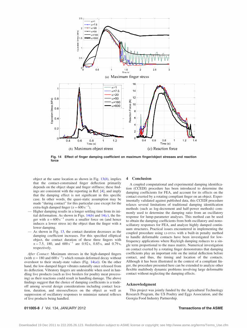
After Contact: Maximum stresses in the high-damped fingers(with a¼ 180 and 600 s�1) which remain deformed decay withoutovershoot to their steady-state values (Fig. 14(a)). On the otherhand, the low-damped finger vibrates naturally once released fromits deflection. Vibratory fingers are undesirable when used in han-dling live products (such as live broilers for poultry meat process-ing) as their reactions could result in handling damage. The abovefindings suggest that the choice of damping coefficients is a trade-off among several design considerations including contact loca-tion, duration, and stresses/forces on the object as well assuppression of oscillatory responses to minimize natural reflexesof live products being handled.
4 Conclusion
A coupled computational and experimental damping identifica-tion (CCEDI) procedure has been introduced to determine thedamping coefficients for FEA, and account for its effects on thecontact exerted by a rotating compliant finger on an object. Exper-imentally validated against published data, this CCEDI procedurerelaxes several limitations of traditional damping identificationmethods (such as log-decrement and half-power methods) com-monly used to determine the damping ratio from an oscillatoryresponse for lump-parameter analyses. This method can be usedto obtain the damping coefficients from both oscillatory and nono-scillatory responses for FEA, and analyze highly damped contin-uum structures. Practical issues encountered in implementing thecoupled procedure using LS-DYNA with a built-in penalty methodto handle deformable contacts have been investigated for low-frequency applications where Rayleigh damping reduces to a sin-gle term proportional to the mass matrix. Numerical investigationon contact exerted by a rotating finger demonstrates that dampingcoefficients play an important role on the initial deflection beforecontact, and thus, the timing and location of the contacts.Although it has been illustrated in the context of a compliant fin-ger, the procedure presented here can be extended to analyze otherflexible multibody dynamic problems involving large deformablecontact without neglecting the damping effects.
Acknowledgment
This project was jointly funded by the Agricultural TechnologyResearch Program, the US Poultry and Eggs Association, and theGeorgia Food Industry Partnership.
Fig. 14 Effect of finger damping coefficient on maximum finger/object stresses and reactionforce
011005-8 / Vol. 134, JANUARY 2012 Transactions of the ASME
Downloaded 19 Dec 2011 to 222.205.26.123. Redistribution subject to ASME license or copyright; see http://www.asme.org/terms/Terms_Use.cfm

Appendix A: Formulation of Dynamic FEM
For a single-element subject to the body force {f}, surface trac-tion {s} and concentrated load {p}, the work balance on the ele-ment (with volume X, surface C, density q and viscous dampingcoefficient c) is given by Eq. (A1)
ðX
duf gT ff gdvþð
Cduf gTfsgdsþ
Xn
i¼1
fdugTi fpgi
¼ð
Xduf gTq €uf g þ duf gTc _uf g þ def gT rf g
� �dv (A1)
In Eq. (A1), the right-hand side accounts for the effects due toinertia, viscosity, and strain energy, respectively; and {du} and{d�} are the virtual displacement and its corresponding strain.
In FE formulation where physical phenomena are analyzed indiscrete domains, the displacement {u} in (A1) is a function ofspace and time, and represented by interpolating functions andnodal DOF, fug ¼ ½N�fxg where [N] is a space-dependent inter-polation function matrix based on the element types; and {x} isthe nodal DOF dependent on time only. Using the constitutiveequations
feg ¼ ½B�fxg (A2a)
frg ¼ ½E�feg ¼ ½E�½B�fxg (A2b)
where [B] and [E] are the strain-displacement and stress-strainmatrixes. Equation (A1) can be written in terms of external load{rext}, and element mass, damping, and stiffness matrices (respec-tively, denoted as [m], [c], and [k])
½m�f€xg þ ½c�f _xg þ ½k�fxg ¼ frextg (A3)
where
½m� ¼ð
Xq½N�T½N�dv (A3a)
½c� ¼ð
Xc½N�T½N�dv (A3b)
½k� ¼ð½B�T½E�½B�dV (A3c)
and
frextg ¼ð
X½N�T½f �dvþ
ðC½N�Tfsgdsþ
Xn
i¼1
fpgi (A3d)
The computational model for the system can be derived by assem-bling (A3) over the whole domain to be analyzed, which leads toEq. (1).
Appendix B: Description of Element Types in General
Explicit Dynamic FEA
The elements types [15] used in this study are summarized inTable 3, which shows the transformation relation between ANSYS
and LS-DYNA, node number for each specific element, and the DOF(displacement U, velocity V, acceleration A, rotation R, and x, y, zdirections). In Table 3, BEAM161 is a line element defined by 2nodes and the beam cross-section; SHELL163 is a 4-node shellelement with bending and membrane capabilities (where in-planeand normal loads are both permitted); SOLID164 (preferred forthe 3D explicit dynamic FEA for time-step considerations) is ahexahedral element used for the solid structures; MASS166 isdefined by a single node with concentrated mass; and SOLID168(useful in modeling 3D complex geometry imported from CADpackages) is a 3D higher-order 10-node tetrahedral element andhas a quadratic displacement behavior.
References[1] Lee, K.-M., 2001, “Design Criteria for Developing an Automated Live-Bird
Transfer System,” IEEE Trans. Rob. Autom., 17(4), pp. 483–490.[2] Howell, L. L., Midha, A., and Norton, T. W., 1996, “Evaluation of Equivalent
Spring Stiffness for Use in a Pseudo-Rigid-Body Model of Large-DeflectionCompliant Mechanisms,” ASME J. Mech. Des., 118, pp. 126–131.
[3] Midha, A., Howell, L. L., and Norton, T. W., 2000, “Limit Positions of Compli-ant Mechanisms Using the Pseudo-Rigid-Body Model Concept,” Mech. Mach.Theory, 35, pp. 99–115.
[4] Lee, K-M., Joni, J., and Yin, X., 2001, “Compliant Grasping Force Modelingfor Handling of Live Objects,” ICRA2001, May 21–26, Seoul, Korea, pp.1059–1064.
[5] Lan, C.-C., and Lee, K.-M., 2008, “An Analytical Contact Model for Design ofCompliant Fingers,” ASME J. Mech. Des., 130, p. 011008.
[6] Li, Q., and Lee, K.-M., 2008, “An Adaptive Meshless Method for ModelingLarge Mechanical Deformation and Contacts,” ASME J. Appl. Mech., 75(4), p.041014.
[7] Pagnini, L. C., and Solari, G., 2001, “Damping Measurements of Steel Polesand Tubular Towers,” Eng. Struct., 23(9), pp. 1085–1095.
[8] Zhu, Z. H., and Meguid, S. A., 2007, “Nonlinear FE-Based Investigation ofFlexural Damping of Slacking Wire Cables,” Int. J. Solids Struct., 44(16), pp.5122–5132.
[9] Drew, S. J., and Stone, B. J., 2002, “Torsional Damping of a Back-to-BackGearbox Rig: Experimental Measurements and Frequency Domain Modeling,”Proc. Inst. Mech. Eng. Part K: J. Multibody Dyn., 216, pp. 157–168.
[10] Low, K. H., Wang, Y., Hoon, K. H., and Vahdati, N., 2004, “Initial Global-Local Analysis for Drop-Impact Effect Study of TV Products,” Adv. Eng. Soft-ware, 35(3–4), pp. 179–190.
[11] LS-DYNA Theory Manual (compiled by J. O. Hallquist), 2006, LivermoreSoftware Technology Corporation.
[12] Cook, R. D., Malkus, D. S., Plesha, M. E., and Witt, R. J., 2001, Concepts andApplications of Finite Element Analysis, 4th ed., Wiley, New York.
[13] Yoo, W.-S., Lee, J.-H., Park, S.-J., Sohn, J.-H., Dmitrochenko, O., and Pogore-lov, D., 2003, “Large Oscillations of a Thin Cantilever Beam: Physical Experi-ments and Simulation Using the Absolute Nodal Coordinate Formulation,”Nonlinear Dyn., 34, pp. 3–29.
[14] Mullen, R., and Belytschko, T., 1983, “An Analysis of an Unconditionally Sta-ble Explicit Method,” Comput. Struct., 16(6), pp. 691–696.
[15] ANSYS Element Reference, Release 12, ANSYS Inc.
Table 3 General element types for explicit dynamic FEA
ANSYS element type BEAM 161 SHELL 163 SOLID 164 MASS l66 SOLID 168
Element plot
Equivalent in LS-DYNA Beam #1 Shell #2 Solid #1 Mass Solid #16Number of nodes 2 4 8 1 10DOFs per nodes 12 12 9 9 3DOF(where i¼x, y, z) Ui, Vi, Ai, Ri, Ui, Vi, Ai, Ri, Ui, Vi, Ai Ui, Vi, Ai Ui
Journal of Dynamic Systems, Measurement, and Control JANUARY 2012, Vol. 134 / 011005-9
Downloaded 19 Dec 2011 to 222.205.26.123. Redistribution subject to ASME license or copyright; see http://www.asme.org/terms/Terms_Use.cfm