Embed Size (px)
Citation preview

Dynamic Finite Element Analyses of a Spent Fuel Transport and Storage Cask with Impact Limiters by
9 Meter Drop Tests
L. Qiao, U. Zencker, A. Musolff and S. Komann
BAM Federal Institute for Materials Research and Testing, 12200 Berlin, Germany
Abstract: The 9 meter drop onto an unyielding target is one of the important mechanical tests within the safety assessment of transport casks for radioactive material. In general, the cask is equipped with impact limiters to reduce the dynamic load on the cask body by absorbing a major part of the kinetic energy. The impact limiters are often made of wood or aluminium. In this study an elastic-plastic material model with volume change was used to describe the stress-strain behaviour of wood found in crush tests. For aluminium, an elastic-incremental plastic material model with Cowper-Symonds parameters for strain rate depending material hardening was used to model the adiabatic stress-strain relations measured at specimens at constant ambient temperature. Hereafter simulations with a sophisticated finite element model were carried out and compared with different drop tests. Four drop tests of a half-scale cask model equipped with wood and aluminium impact limiters with different drop positions were selected to investigate the impact limiter behaviour during a 9 meter drop test. All drop tests were simulated with the same FE mesh but under different boundary and initial conditions. Keywords: Cask, Drop test, Impact limiter, Wood, Aluminium, Dynamics.
1. Introduction
The safety assessment of new designs for transport and storage casks for radioactive materials is a challenging task by using different methods like prototype tests, model tests, calculations and analogy reflections. At BAM (Federal Institute for Materials Research and Testing), the test procedures for the mechanical IAEA (International Atomic Energy Agency) test conditions start often with preliminary finite element calculations mostly with a small-scale cask model for verification of the proposed test cask instrumentation and test plan. On that basis the extensive test cask instrumentation is applied and checked. After that, drop test series consisting of different test sequences are performed.
Following the drop tests, numerical post-analyses are carried out. These analyses offer the possibility of a detailed calculation and assessment of stresses and strains in the entire test cask construction. The calculation results have to be carefully compared with the measurement data over the impact history to find out all relevant parameters for a realistic simulation of the impact scenario. The desired ideal boundary test conditions often cannot be met exactly during the 9 meter free drop. Therefore, the numerical post-analyses are carried out by using the real boundary conditions of the drop tests. The objective is to find a validated model, where the results of the numerical simulations meet satisfactorily the experimental results.
2011 SIMULIA Customer Conference 1
Under test conditions according to the IAEA transport regulations (IAEA, 2009), casks are usually equipped with impact limiters and dropped onto a so-called unyielding target. In this paper a study is presented, where the influence of different impact positions on the cask loading is investigated. The results of the numerical simulations are compared with drop test results of the half-scale cask model CASTOR® HAW/TB2.
BAM has carried out the drop test series and studied the test scenarios with sophisticated finite element models using Abaqus/Explicit. Results from basic research of crush phenomena of impact limiters are presented. Hence it is possible to interpret the test results in detail by means of modern finite element analyses.
2. Drop test program
For transport and storage of vitrified High Level Waste (HLW) from reprocessing a new cask design was developed by German company GNS Gesellschaft für Nuklear-Service mbH, Essen (Voßnacke, 2004, Völzer, 2010). BAM as part of the competent authority system in Germany is responsible for the assessment of mechanical and thermal safety analyses and quality-assurance measures within the complete evaluation of the Safety Analysis Report (SAR). An extensive drop test program with an instrumented half-scale model was carried out on the 200 tons BAM drop test facility (Musolff, 2010, Droste, 2009).
Figure 1. Drop test program with half-scale model CASTOR® HAW/TB2 (source: GNS)
2 2011 SIMULIA Customer Conference
The drop test program for the transport approval procedure is shown in figure 1. There were altogether 17 drop tests with different drop orientations, drop heights and temperatures. The cask was instrumented with altogether 23 accelerometers, 5 temperature sensors and 131 tri-axial strain gauges. The test program included 9 meter free drop tests with impact limiters onto the so-called unyielding IAEA target to cause the possible maximum cask and impact limiter damage, 1 meter drop tests onto a steel puncture bar at the most sensitive parts of the cask to cause the possible local damage of the cask body and an additional 0.3 meter drop onto the unyielding target without impact limiter considering the licensing procedure conditions for interim storage in Germany.
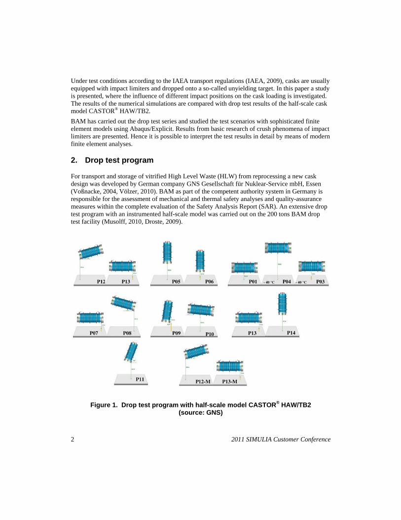
a) P05 b) P14
c) P04 d) P10
Figure 2. Half-scale model shortly before the 9 meter drop tests (source: BAM)
In this study four different drop tests (P05, P14, P04 and P10) for the research of impact limiter behaviour were used. Among other assessment goals, the vertical drop tests on the lid side of the cask (P05) and the bottom side of the cask (P14) were performed for testing of the lid and bottom
2011 SIMULIA Customer Conference 3
impact limiter, which are made of wood. The 9 m horizontal drop test (P04) was performed for testing jacket impact limiters, which are made of aluminium. The slap-down drop test (P10) with an impact angle of 5 degrees was performed to analyse the combined behaviour of lid and jacket impact limiter. Figure 2 shows the test cask shortly before the four drop tests.
3. Finite element model
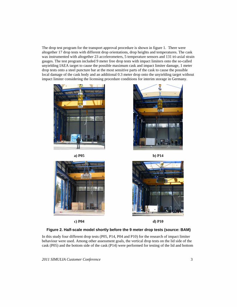
The competent authority BAM developed a finite element model (FE model) for mechanical design assessment independently of the applicant. Thereby the different test scenarios were considered. The FE model (figure 3) of the drop test cask CASTOR® HAW/TB2 was built in a detailed manner to get reliable and accurate results. These numerical results were compared with test data to validate the FE model. The model consists of the following main components:
cask body made of ductile cast iron with moderator boreholes, primary lid and lid screws, four trunnions, model canisters, model graphite columns, moderator plate on the cask bottom, closing plate on the cask bottom, bottom end and lid end impact limiter filled with wood, three jacket impact limiters made of aluminium.
Figure 3. FE Model of the half-scale model CASTOR® HAW/TB2
The gross weight is approximately 14.5 Mg. The complete FE model has about 300,000 elements and 400,000 nodes. It was built up with 3D solid elements of Abaqus type C3D8R with linear interpolation and reduced integration for the dynamic simulation. All free surfaces (between cask body and canisters, cask body and primary lid, cask body and impact limiter as well as between impact limiter and foundation) were defined by using Abaqus option "general contact". In the first step the 0.3 m drop test onto the unyielding target without impact limiter was successfully simulated (Qiao, 2008). So it was possible to verify the numerical model of the cask structure only. After that the complicated impact limiter structure and their connections were added in the FE model to simulate the 9 m drop tests.
4 2011 SIMULIA Customer Conference
4. Material model of wood
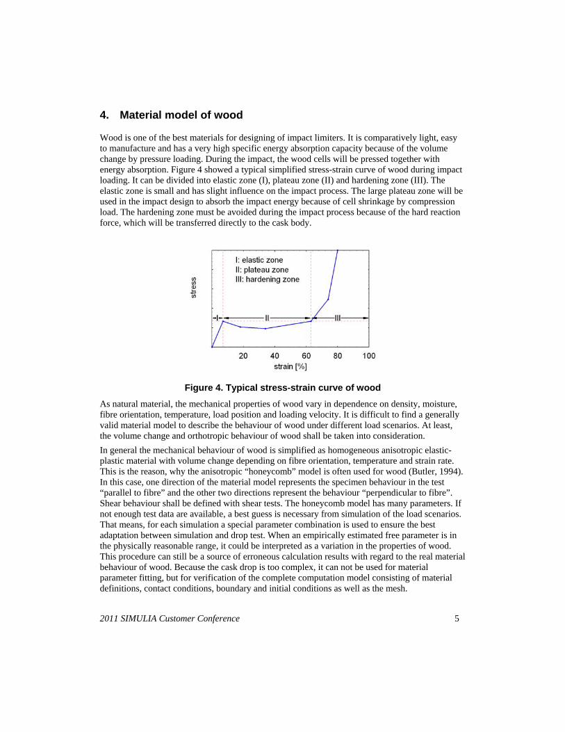
Wood is one of the best materials for designing of impact limiters. It is comparatively light, easy to manufacture and has a very high specific energy absorption capacity because of the volume change by pressure loading. During the impact, the wood cells will be pressed together with energy absorption. Figure 4 showed a typical simplified stress-strain curve of wood during impact loading. It can be divided into elastic zone (I), plateau zone (II) and hardening zone (III). The elastic zone is small and has slight influence on the impact process. The large plateau zone will be used in the impact design to absorb the impact energy because of cell shrinkage by compression load. The hardening zone must be avoided during the impact process because of the hard reaction force, which will be transferred directly to the cask body.
Figure 4. Typical stress-strain curve of wood
As natural material, the mechanical properties of wood vary in dependence on density, moisture, fibre orientation, temperature, load position and loading velocity. It is difficult to find a generally valid material model to describe the behaviour of wood under different load scenarios. At least, the volume change and orthotropic behaviour of wood shall be taken into consideration.
In general the mechanical behaviour of wood is simplified as homogeneous anisotropic elastic-plastic material with volume change depending on fibre orientation, temperature and strain rate. This is the reason, why the anisotropic “honeycomb” model is often used for wood (Butler, 1994). In this case, one direction of the material model represents the specimen behaviour in the test “parallel to fibre” and the other two directions represent the behaviour “perpendicular to fibre”. Shear behaviour shall be defined with shear tests. The honeycomb model has many parameters. If not enough test data are available, a best guess is necessary from simulation of the load scenarios. That means, for each simulation a special parameter combination is used to ensure the best adaptation between simulation and drop test. When an empirically estimated free parameter is in the physically reasonable range, it could be interpreted as a variation in the properties of wood. This procedure can still be a source of erroneous calculation results with regard to the real material behaviour of wood. Because the cask drop is too complex, it can not be used for material parameter fitting, but for verification of the complete computation model consisting of material definitions, contact conditions, boundary and initial conditions as well as the mesh.
2011 SIMULIA Customer Conference 5
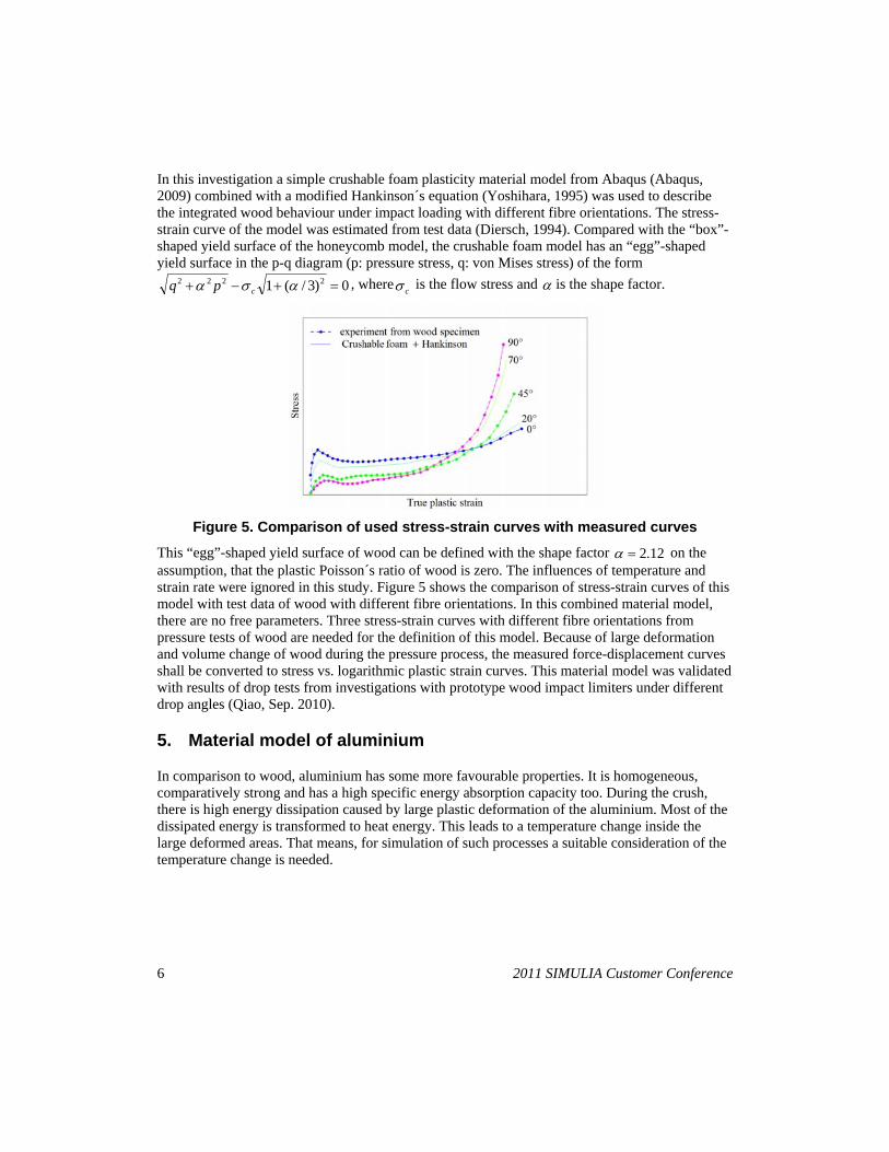
In this investigation a simple crushable foam plasticity material model from Abaqus (Abaqus, 2009) combined with a modified Hankinson´s equation (Yoshihara, 1995) was used to describe the integrated wood behaviour under impact loading with different fibre orientations. The stress-strain curve of the model was estimated from test data (Diersch, 1994). Compared with the “box”-shaped yield surface of the honeycomb model, the crushable foam model has an “egg”-shaped yield surface in the p-q diagram (p: pressure stress, q: von Mises stress) of the form
0)3/(1 2222 cpq , wherec is the flow stress and is the shape factor.
Figure 5. Comparison of used stress-strain curves with measured curves
This “egg”-shaped yield surface of wood can be defined with the shape factor 12.2 on the assumption, that the plastic Poisson´s ratio of wood is zero. The influences of temperature and strain rate were ignored in this study. Figure 5 shows the comparison of stress-strain curves of this model with test data of wood with different fibre orientations. In this combined material model, there are no free parameters. Three stress-strain curves with different fibre orientations from pressure tests of wood are needed for the definition of this model. Because of large deformation and volume change of wood during the pressure process, the measured force-displacement curves shall be converted to stress vs. logarithmic plastic strain curves. This material model was validated with results of drop tests from investigations with prototype wood impact limiters under different drop angles (Qiao, Sep. 2010).
5. Material model of aluminium
In comparison to wood, aluminium has some more favourable properties. It is homogeneous, comparatively strong and has a high specific energy absorption capacity too. During the crush, there is high energy dissipation caused by large plastic deformation of the aluminium. Most of the dissipated energy is transformed to heat energy. This leads to a temperature change inside the large deformed areas. That means, for simulation of such processes a suitable consideration of the temperature change is needed.
6 2011 SIMULIA Customer Conference
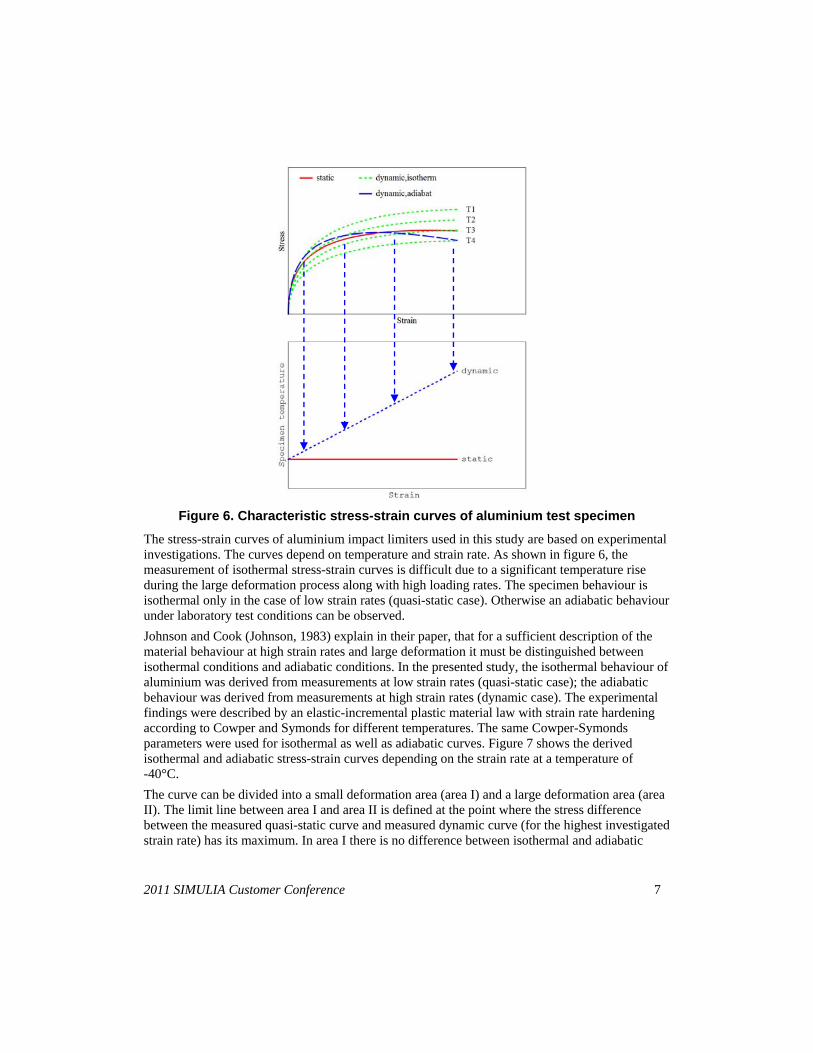
Figure 6. Characteristic stress-strain curves of aluminium test specimen
The stress-strain curves of aluminium impact limiters used in this study are based on experimental investigations. The curves depend on temperature and strain rate. As shown in figure 6, the measurement of isothermal stress-strain curves is difficult due to a significant temperature rise during the large deformation process along with high loading rates. The specimen behaviour is isothermal only in the case of low strain rates (quasi-static case). Otherwise an adiabatic behaviour under laboratory test conditions can be observed.
Johnson and Cook (Johnson, 1983) explain in their paper, that for a sufficient description of the material behaviour at high strain rates and large deformation it must be distinguished between isothermal conditions and adiabatic conditions. In the presented study, the isothermal behaviour of aluminium was derived from measurements at low strain rates (quasi-static case); the adiabatic behaviour was derived from measurements at high strain rates (dynamic case). The experimental findings were described by an elastic-incremental plastic material law with strain rate hardening according to Cowper and Symonds for different temperatures. The same Cowper-Symonds parameters were used for isothermal as well as adiabatic curves. Figure 7 shows the derived isothermal and adiabatic stress-strain curves depending on the strain rate at a temperature of -40°C.
The curve can be divided into a small deformation area (area I) and a large deformation area (area II). The limit line between area I and area II is defined at the point where the stress difference between the measured quasi-static curve and measured dynamic curve (for the highest investigated strain rate) has its maximum. In area I there is no difference between isothermal and adiabatic
2011 SIMULIA Customer Conference 7
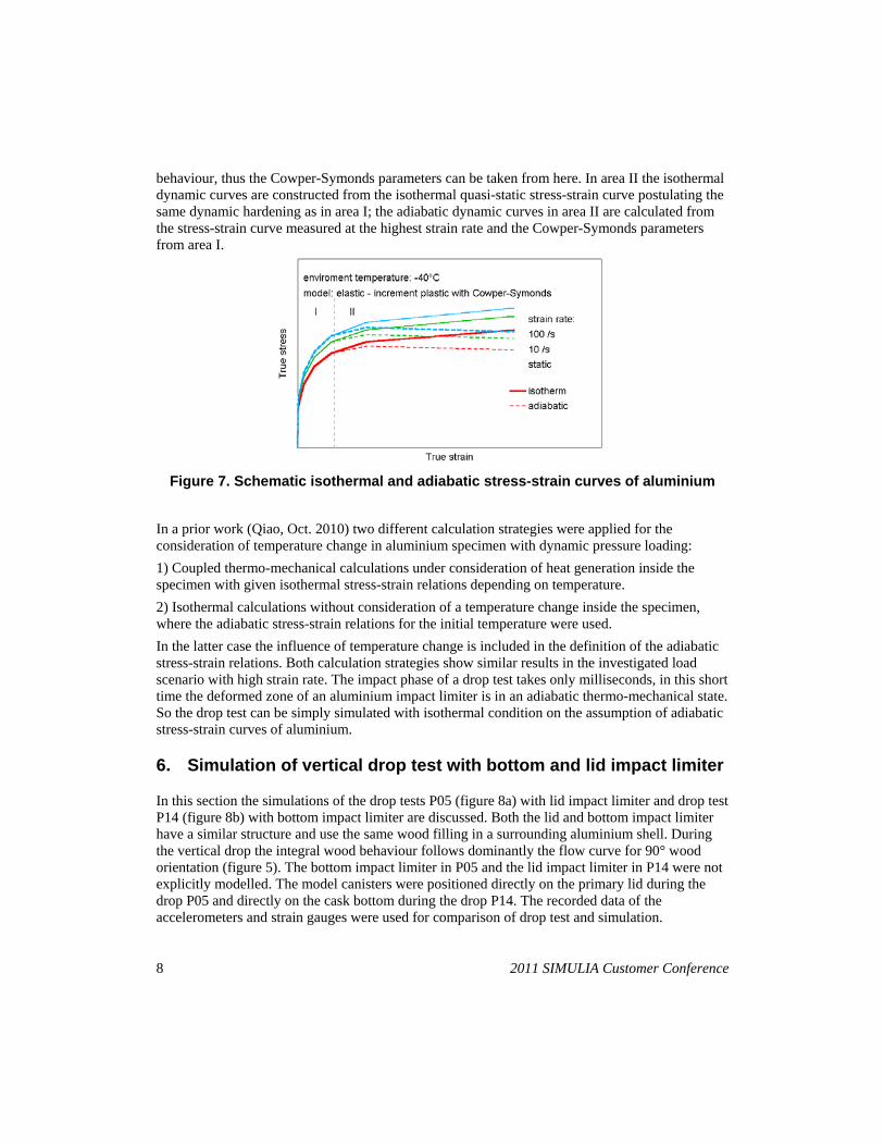
behaviour, thus the Cowper-Symonds parameters can be taken from here. In area II the isothermal dynamic curves are constructed from the isothermal quasi-static stress-strain curve postulating the same dynamic hardening as in area I; the adiabatic dynamic curves in area II are calculated from the stress-strain curve measured at the highest strain rate and the Cowper-Symonds parameters from area I.
Figure 7. Schematic isothermal and adiabatic stress-strain curves of aluminium
In a prior work (Qiao, Oct. 2010) two different calculation strategies were applied for the consideration of temperature change in aluminium specimen with dynamic pressure loading:
1) Coupled thermo-mechanical calculations under consideration of heat generation inside the specimen with given isothermal stress-strain relations depending on temperature.
2) Isothermal calculations without consideration of a temperature change inside the specimen, where the adiabatic stress-strain relations for the initial temperature were used.
In the latter case the influence of temperature change is included in the definition of the adiabatic stress-strain relations. Both calculation strategies show similar results in the investigated load scenario with high strain rate. The impact phase of a drop test takes only milliseconds, in this short time the deformed zone of an aluminium impact limiter is in an adiabatic thermo-mechanical state. So the drop test can be simply simulated with isothermal condition on the assumption of adiabatic stress-strain curves of aluminium.
6. Simulation of vertical drop test with bottom and lid impact limiter
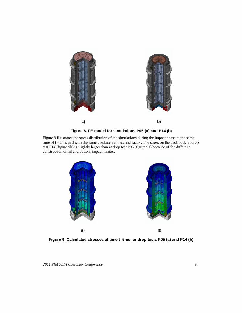
In this section the simulations of the drop tests P05 (figure 8a) with lid impact limiter and drop test P14 (figure 8b) with bottom impact limiter are discussed. Both the lid and bottom impact limiter have a similar structure and use the same wood filling in a surrounding aluminium shell. During the vertical drop the integral wood behaviour follows dominantly the flow curve for 90° wood orientation (figure 5). The bottom impact limiter in P05 and the lid impact limiter in P14 were not explicitly modelled. The model canisters were positioned directly on the primary lid during the drop P05 and directly on the cask bottom during the drop P14. The recorded data of the accelerometers and strain gauges were used for comparison of drop test and simulation.
8 2011 SIMULIA Customer Conference
a) b)
Figure 8. FE model for simulations P05 (a) and P14 (b)
Figure 9 illustrates the stress distribution of the simulations during the impact phase at the same time of t = 5ms and with the same displacement scaling factor. The stress on the cask body at drop test P14 (figure 9b) is slightly larger than at drop test P05 (figure 9a) because of the different construction of lid and bottom impact limiter.
a) b)
Figure 9. Calculated stresses at time t=5ms for drop tests P05 (a) and P14 (b)
2011 SIMULIA Customer Conference 9
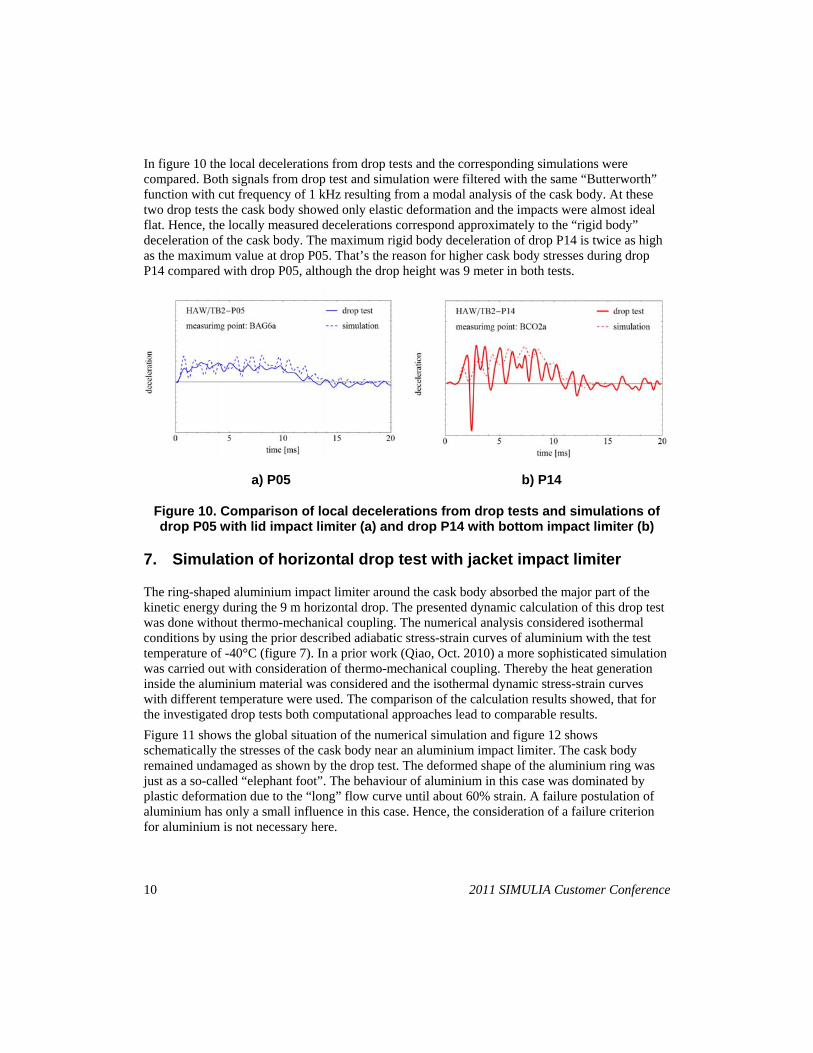
In figure 10 the local decelerations from drop tests and the corresponding simulations were compared. Both signals from drop test and simulation were filtered with the same “Butterworth” function with cut frequency of 1 kHz resulting from a modal analysis of the cask body. At these two drop tests the cask body showed only elastic deformation and the impacts were almost ideal flat. Hence, the locally measured decelerations correspond approximately to the “rigid body” deceleration of the cask body. The maximum rigid body deceleration of drop P14 is twice as high as the maximum value at drop P05. That’s the reason for higher cask body stresses during drop P14 compared with drop P05, although the drop height was 9 meter in both tests.
a) P05 b) P14
Figure 10. Comparison of local decelerations from drop tests and simulations of drop P05 with lid impact limiter (a) and drop P14 with bottom impact limiter (b)
7. Simulation of horizontal drop test with jacket impact limiter
The ring-shaped aluminium impact limiter around the cask body absorbed the major part of the kinetic energy during the 9 m horizontal drop. The presented dynamic calculation of this drop test was done without thermo-mechanical coupling. The numerical analysis considered isothermal conditions by using the prior described adiabatic stress-strain curves of aluminium with the test temperature of -40°C (figure 7). In a prior work (Qiao, Oct. 2010) a more sophisticated simulation was carried out with consideration of thermo-mechanical coupling. Thereby the heat generation inside the aluminium material was considered and the isothermal dynamic stress-strain curves with different temperature were used. The comparison of the calculation results showed, that for the investigated drop tests both computational approaches lead to comparable results.
Figure 11 shows the global situation of the numerical simulation and figure 12 shows schematically the stresses of the cask body near an aluminium impact limiter. The cask body remained undamaged as shown by the drop test. The deformed shape of the aluminium ring was just as a so-called “elephant foot”. The behaviour of aluminium in this case was dominated by plastic deformation due to the “long” flow curve until about 60% strain. A failure postulation of aluminium has only a small influence in this case. Hence, the consideration of a failure criterion for aluminium is not necessary here.
10 2011 SIMULIA Customer Conference
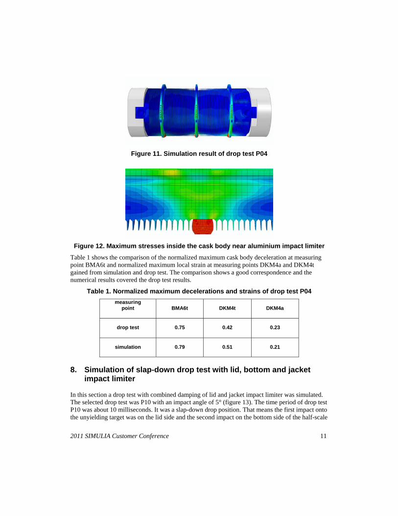
Figure 11. Simulation result of drop test P04
Figure 12. Maximum stresses inside the cask body near aluminium impact limiter
Table 1 shows the comparison of the normalized maximum cask body deceleration at measuring point BMA6t and normalized maximum local strain at measuring points DKM4a and DKM4t gained from simulation and drop test. The comparison shows a good correspondence and the numerical results covered the drop test results.
Table 1. Normalized maximum decelerations and strains of drop test P04
measuring point
BMA6t
DKM4t
DKM4a
drop test
0.75
0.42
0.23
simulation
0.79
0.51
0.21
8. Simulation of slap-down drop test with lid, bottom and jacket impact limiter
In this section a drop test with combined damping of lid and jacket impact limiter was simulated. The selected drop test was P10 with an impact angle of 5° (figure 13). The time period of drop test P10 was about 10 milliseconds. It was a slap-down drop position. That means the first impact onto the unyielding target was on the lid side and the second impact on the bottom side of the half-scale
2011 SIMULIA Customer Conference 11
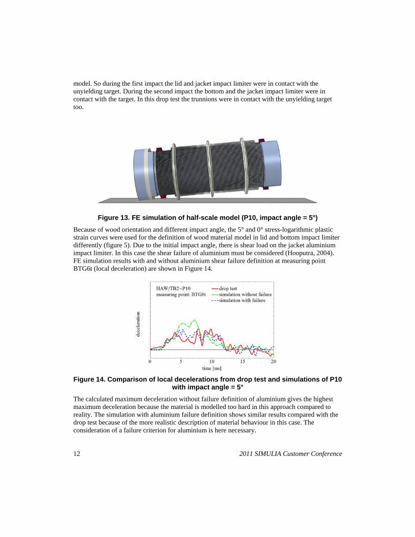
model. So during the first impact the lid and jacket impact limiter were in contact with the unyielding target. During the second impact the bottom and the jacket impact limiter were in contact with the target. In this drop test the trunnions were in contact with the unyielding target too.
Figure 13. FE simulation of half-scale model (P10, impact angle = 5°)
Because of wood orientation and different impact angle, the 5° and 0° stress-logarithmic plastic strain curves were used for the definition of wood material model in lid and bottom impact limiter differently (figure 5). Due to the initial impact angle, there is shear load on the jacket aluminium impact limiter. In this case the shear failure of aluminium must be considered (Hooputra, 2004). FE simulation results with and without aluminium shear failure definition at measuring point BTG6t (local deceleration) are shown in Figure 14.
Figure 14. Comparison of local decelerations from drop test and simulations of P10 with impact angle = 5°
The calculated maximum deceleration without failure definition of aluminium gives the highest maximum deceleration because the material is modelled too hard in this approach compared to reality. The simulation with aluminium failure definition shows similar results compared with the drop test because of the more realistic description of material behaviour in this case. The consideration of a failure criterion for aluminium is here necessary.
12 2011 SIMULIA Customer Conference
9. Conclusions
In this work, four drop tests of a half-scale cask model equipped with impact limiters under different drop positions were selected to investigate the impact limiter behaviour during 9 meter drop. All drop tests were simulated with the same FE mesh. At first, for verification purposes of the FE model, the drop test of 0.3 m without impact limiter directly onto the unyielding target was carried out and successfully simulated. After that the FE model with impact limiters and their connections to the cask body were developed to simulate other drop tests with impact limiters. In this paper the results of these simulations were presented. So the following conclusions are possible. In general, it is difficult to verify of a complex FE model by using only results from one drop test, because of the complex impact process and the complex structure of such packages. After each drop test, numerical post-analyses should be carried out. Only if all drop tests were simulated successfully by using the same FE model under different test conditions, it is possible to get a validated numerical model for further investigations. In this case the results of the numerical simulations meet satisfactorily the experimental results.
After that the validated scaled FE model can be scaled up to a full scale model to analyze and assess the original cask design. In this way the maximum stressed cask areas and components can be identified and evaluated for safety assessments with respect to e.g. fracture mechanics analysis, local plastic deformation and leak-tightness of sealed lid systems.
10. References
1. Abaqus, “Analysis User’s Manual”, Volume III: Materials, Version 6.9, Dassault Systemes, 2009.
2. Butler, N., “Computer modelling of wood-filled impact limiters”, Nuclear Engineering and Design 150 (1994), pp 417-424, Elsevier Science S.A., 1994.
3. Diersch, R., M. Weiss and G. Dreier, “Investigation of the impact behaviour of wooden impact limiters”, Nuclear Engineering and Design 150 (1994), pp 341-348, Elsevier Science S.A., 1994.
4. Droste, B., K. Müller, A. Musolff, and A. Ulrich, “BAM Test Site Technical Safety – The installations for mechanical and thermal Package testing –”, Radioactive Materials Transport Conference 2009, Manchester, England, May 12-14, 2009.
5. Hooputra, H., H. Gese, H. Dell and H. Werner, “A Comprehensive Failure Model for Crashworthiness Simulation of Aluminium Extrusions”, International Journal of Crashworthiness, vol. 9, pp. 449-463, 2004.
6. International Atomic Energy Agency (IAEA), “Regulations for the Safe Transport of Radioactive Material”, 2009 Edition, Safety Standard Series No. TS-R-1, Vienna, 2009.
7. Johnson, G. R. and W. H. Cook, “A Constitutive Model and Data for Metals Subjected to Large Strains, High Strain Rates and High Temperatures”, Proc. 7 th Int. Symp. On Ballistics, pp. 541-547, The Hague, The Netherlands, April 1983.
8. Musolff, A., T. Quercetti, K. Müller, B. Droste and S. Komann, “Drop test program with the half-scale model CASTOR® HAW/TB2”, 16th Int. Symposium on the Packaging and Transportation of Radioactive Materials (PATRAM 2010), London, UK, October 3-8, 2010.
2011 SIMULIA Customer Conference 13
14 2011 SIMULIA Customer Conference
9. Qiao, L., U. Zencker, G. Wieser and H. Völzke, “Numerical Safety Assessment of a Transport and Storage Cask for Radioactive Materials without Impact Limiters by the 0,3m Drop Test onto an Unyielding Target”, 9th International Conference on Computational Structures Technology, Athens, Greece, September 2-5, 2008.
10. Qiao, L., V. Ballheimer, G. Wieser, U. Zencker and T. Quercetti, “Numerische Simulation von Fallversuchen mit Behälterstoßdämpfern bei unterschiedlichen Fallwinkeln mittels Abaqus/Explicit”, Deutsche SIMULIA-Konferenz 2010, Heidelberg, September 20-21, 2010.
11. Qiao, L., U. Zencker, F. Wille and A. Musolff, “Numerical Simulation of 9 meter drop of a transport and storage cask with aluminium impact limiter”, 16th Int. Symposium on the Packaging and Transportation of Radioactive Materials (PATRAM 2010), London, UK, October 3-8, 2010.
12. Völzer, W., S. Glutsch, R. Perez-Kretschmer and P. Vrastil, “Verification of computational models by comparison of finite-element calculations and experiments for the model cask CASTOR® HAW/TB2”, 16th Int. Symposium on the Packaging and Transportation of Radioactive Materials (PATRAM 2010), London, UK, October 3-8, 2010.
13. Voßnacke, A., K. Klein and B. Kühne, “CASTOR® HAW28M – a High Heat Load Cask for Transport and Storage of Vitrified High Level Waste Containers”, Proceedings of the 14th Int. Symposium on the Packaging and Transportation of Radioactive Materials (PATRAM 2004), Berlin, Germany, September 20-24, 2004.
14. Yoshihara, H., S. Amano and M. Ohta, “Relationship between the Strength and Grain Orientation of Wood –Examination and Modification of the Hankinson’s Formula-”, Bull. Tokyo Univ. For., 93, 1-5, 1995.