Embed Size (px)
Citation preview
Dynamic Characteristics Analysis of the Hydraulic Arm of Mobile Coal Sampling Robot
Yuanfang Li1, Haibo Xu1, Jun Wang2, Rong Deng1 and Yufeng Lin1 1Xi'an Jiaotong University, Xi’an 710049, Shanxi, China
2Xi'an Hongyu mining special mobile equipment Co., Xi’an 710075, Shaanxi, China
Abstract—Dynamic characteristics of the hydraulic arm affects the mobile coal sampling robot’s accuracy and efficiency. The complex and varied working conditions put many high requirements on the stability of the hydraulic arm. This paper took the hydraulic arm of the MCYY2000 mobile coal sampling robot as the research object, and established a simplified model of the hydraulic arm with SolidWorks. It carried out the analysis under both the condition of no-sampling resistance and the condition of variable sampling resistance. The analysis was done with the module of multi-body dynamics simulation in Simulink. This paper helps to obtain the joint torques and hydraulic driving forces of the hydraulic arm under different conditions. The results provide a basis for further work including accurate motion control, chatter reduction and safety improvement of the coal sampling robot.
Keywords—coal sampling robot; hydraulic arm; complex working conditions; dynamic characteristics
I. INTRODUCTION
The mobile coal sampling robot is suitable for the sampling of carts, trains and coal heaps in places such as coal yards, steel mills, power plants, and harbors[1]. With its advantages of small size, high mobility, and wide adaptability, it has demonstrated an important position in the industry of mechanized coal sampling in recent years. Compared to manual sampling, the mobile coal sampling robot can reduce labor intensity and increase sampling efficiency[2].
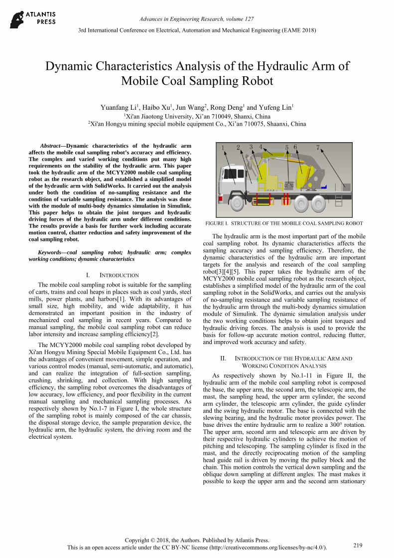
The MCYY2000 mobile coal sampling robot developed by Xi'an Hongyu Mining Special Mobile Equipment Co., Ltd. has the advantages of convenient movement, simple operation, and various control modes (manual, semi-automatic, and automatic), and can realize the integration of full-section sampling, crushing, shrinking, and collection. With high sampling efficiency, the sampling robot overcomes the disadvantages of low accuracy, low efficiency, and poor flexibility in the current manual sampling and mechanical sampling processes. As respectively shown by No.1-7 in Figure I, the whole structure of the sampling robot is mainly composed of the car chassis, the disposal storage device, the sample preparation device, the hydraulic arm, the hydraulic system, the driving room and the electrical system.
FIGURE I. STRUCTURE OF THE MOBILE COAL SAMPLING ROBOT
The hydraulic arm is the most important part of the mobile coal sampling robot. Its dynamic characteristics affects the sampling accuracy and sampling efficiency. Therefore, the dynamic characteristics of the hydraulic arm are important targets for the analysis and research of the coal sampling robot[3][4][5]. This paper takes the hydraulic arm of the MCYY2000 mobile coal sampling robot as the research object, establishes a simplified model of the hydraulic arm of the coal sampling robot in the SolidWorks, and carries out the analysis of no-sampling resistance and variable sampling resistance of the hydraulic arm through the multi-body dynamics simulation module of Simulink. The dynamic simulation analysis under the two working conditions helps to obtain joint torques and hydraulic driving forces. The analysis is used to provide the basis for follow-up accurate motion control, reducing flutter, and improved work accuracy and safety.
II. INTRODUCTION OF THE HYDRAULIC ARM AND
WORKING CONDITION ANALYSIS
As respectively shown by No.1-11 in Figure II, the hydraulic arm of the mobile coal sampling robot is composed the base, the upper arm, the second arm, the telescopic arm, the mast, the sampling head, the upper arm cylinder, the second arm cylinder, the telescopic arm cylinder, the guide cylinder and the swing hydraulic motor. The base is connected with the slewing bearing, and the hydraulic motor provides power. The base drives the entire hydraulic arm to realize a 300° rotation. The upper arm, second arm and telescopic arm are driven by their respective hydraulic cylinders to achieve the motion of pitching and telescoping. The sampling cylinder is fixed in the mast, and the directly reciprocating motion of the sampling head guide rail is driven by moving the pulley block and the chain. This motion controls the vertical down sampling and the oblique down sampling at different angles. The mast makes it possible to keep the upper arm and the second arm stationary
3rd International Conference on Electrical, Automation and Mechanical Engineering (EAME 2018)
Copyright © 2018, the Authors. Published by Atlantis Press. This is an open access article under the CC BY-NC license (http://creativecommons.org/licenses/by-nc/4.0/).
Advances in Engineering Research, volume 127
219

during sampling, so the sampling accuracy can be higher. The sampling head is a spiral structure[6] and can complete the deep sampling into coal heaps with a depth of 2 meters.
FIGURE II. STRUCTURE OF THE HYDRAULIC ARM
The related size parameters of the hydraulic arm of the coal sampling robot are shown in Table I. The parameters in the table are all from the actual design parameters of the MCYY2000 mobile coal sampling robot.
TABLE I. RELATED SIZES OF THE HYDRAULIC ARM
Component Size / mm
upper arm 2900
second arm 2700
telescopic arm 1000
mast 3400
Sampling head 2100
Complex and varied working conditions[7] of coal sampling projects put many high requirements on the stability of the dynamic characteristics of the hydraulic arm:
(1) When the sampling head of the hydraulic arm is moving at a low speed and operating the pitching movement with no-sampling resistance, the torque of each joint and the driving force of the hydraulic cylinder should be changed smoothly with small amplitude, so that the hydraulic arm can maintain safety and stability during its adjustment of the sampling angle.
(2) When the hydraulic arm is sampling at a fixed sampling angle, the sampling head is subject to a varying sampling resistance. At this time, the joint torques and the hydraulic driving forces must avoid sharp changes or exceeding its safety range[8] so that the coal sampling robot can stay safe. The key research of this paper focuses on the dynamic characteristics of the hydraulic arm of the coal sampling robot under the two working conditions.
III. ANALYSIS OF DYNAMIC CHARACTERISTICS OF THE
HYDRAULIC ARM
To build a virtual prototype, simplified models should be used as much as possible. In order to reduce the simulation time[9], the number of parts should be reduced as much as
possible while satisfying the integrity of the virtual prototyping simulation movement. According to the actual size of the hydraulic arm and the types of hydraulic cylinders, the components including the base, the upper arm, the second arm, the telescopic arm, the mast, the sampling head and hydraulic cylinders are modeled and assembled in SolidWorks. The virtual prototype of the hydraulic arm of the coal sampling robot is shown in Figure III.
FIGURE III. VIRTUAL PROTOTYPE MODEL OF THE HYDRAULIC
ARM
As shown by No.1-8 in Figure IV. the simplified schematic diagram of the movement mechanism includes three joints - join1, joint2 and joint3 - and five hydraulic cylinders - cylinder1, cylinder2, cylinder3, cylinder4 and cylinder5. The range of the motion of each joint variable and cylinder driving variable is shown in Table II.
FIGURE IV. MOTION MECHANISM OF THE HYDRAULIC ARM OF
THE COAL SAMPLING ROBOT
TABLE II. RANGE OF JOINT ANGLES AND CYLINDER LENGTHS
Joint angle Range /(°) Cylinder length Range / mm
joint θ1 66-130 cylinder s1 1750-2750
joint θ2 90-160 cylinder s2 1450-2300
cylinder s3 2700-3700
joint θ3 60-135 cylinder s4 1650-2650
cylinder s5 3400-5500
Advances in Engineering Research, volume 127
220

Import the assembled model into Simulink and generate a block diagram of the model. Set the appropriate material properties and apply the necessary constraints[10] for each component in the model, and add torque sensors and force sensors for the rotating joints and hydraulic cylinders. The signal window modules are also added. The general Simulink dynamic analysis block diagram after settings is shown in Figure V. The multibody structure diagram of the hydraulic arm is shown in Figure VI.
FIGURE V. GENERAL SIMULINK DYNAMIC ANALYSIS BLOCK
DIAGRAM
FIGURE VI. SIMSCAPE MULTIBODY STRUCTURE DIAGRAM
A. Analysis of the Dynamic Characteristics of the Hydraulic Arm of Coal Sampling Robot under the Condition of No-sampling Resistance
When the hydraulic arm is under the no-sampling resistance condition, the sampling head only performs low-speed pitching movements. At this time, each joint torque and the hydraulic cylinder driving force should be stable and be of small-scale changes, so that the coal sampling robot can remain safe and stable during the adjustment of its sampling angle. When analyzing the dynamic characteristics of the hydraulic arm under this condition, the sampling resistance is set to zero. The curve of the length of the hydraulic cylinder s4 is shown in Figure VII. The lengths of cylinders s1, s2, s3 and s5 are respectively set to 2250mm, 1950mm, 2700mm and 3400mm. According to the relationship between the joint variables and the cylinder driving variables, the curve of the joint angle θ3 is shown in Figure VIII.
FIGURE VII. CURVE OF THE LENGTH OF CYLINDER 4
FIGURE VIII. CURVE OF JOINT ANGLE θ3
The curves of the joint torques and the hydraulic cylinder driving forces are respectively shown in Figure IX and Figure X. With the extension and retraction of the mast cylinder s4, the torques of the joint1-joint3 firstly increase and then decrease within a smaller range, and the change trend is relatively stable. The torque of joint1 is the largest. The torque of joint2 is the next, and the torque of joint3 is the smallest. The driving forces of the hydraulic cylinders also change smoothly. The driving force of the hydraulic cylinder1 is the largest, and the driving force of the hydraulic cylinder3 remains basically unchanged.
The results show that when the hydraulic arm of the coal sampling robot performs low-speed swing movement of its sampling head under the condition of no-sampling resistance, the joint torques and the driving forces of the hydraulic cylinders change smoothly and slightly. The driving forces of the hydraulic cylinders mainly overcome the effect of gravity. The simulation results are in accordance with the actual situation.
Advances in Engineering Research, volume 127
221
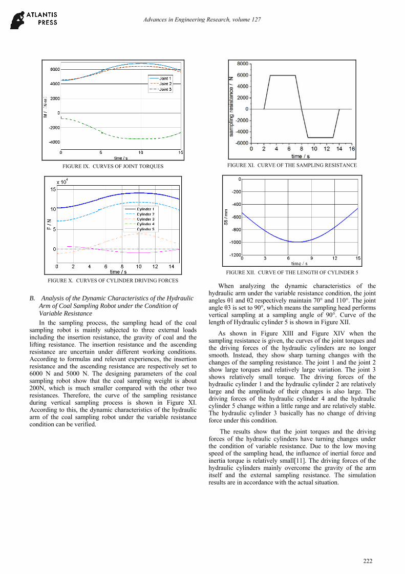
FIGURE IX. CURVES OF JOINT TORQUES
FIGURE X. CURVES OF CYLINDER DRIVING FORCES
B. Analysis of the Dynamic Characteristics of the Hydraulic Arm of Coal Sampling Robot under the Condition of Variable Resistance
In the sampling process, the sampling head of the coal sampling robot is mainly subjected to three external loads including the insertion resistance, the gravity of coal and the lifting resistance. The insertion resistance and the ascending resistance are uncertain under different working conditions. According to formulas and relevant experiences, the insertion resistance and the ascending resistance are respectively set to 6000 N and 5000 N. The designing parameters of the coal sampling robot show that the coal sampling weight is about 200N, which is much smaller compared with the other two resistances. Therefore, the curve of the sampling resistance during vertical sampling process is shown in Figure XI. According to this, the dynamic characteristics of the hydraulic arm of the coal sampling robot under the variable resistance condition can be verified.
FIGURE XI. CURVE OF THE SAMPLING RESISTANCE
FIGURE XII. CURVE OF THE LENGTH OF CYLINDER 5
When analyzing the dynamic characteristics of the hydraulic arm under the variable resistance condition, the joint angles θ1 and θ2 respectively maintain 70° and 110°. The joint angle θ3 is set to 90°, which means the sampling head performs vertical sampling at a sampling angle of 90°. Curve of the length of Hydraulic cylinder 5 is shown in Figure XII.
As shown in Figure XIII and Figure XIV when the sampling resistance is given, the curves of the joint torques and the driving forces of the hydraulic cylinders are no longer smooth. Instead, they show sharp turning changes with the changes of the sampling resistance. The joint 1 and the joint 2 show large torques and relatively large variation. The joint 3 shows relatively small torque. The driving forces of the hydraulic cylinder 1 and the hydraulic cylinder 2 are relatively large and the amplitude of their changes is also large. The driving forces of the hydraulic cylinder 4 and the hydraulic cylinder 5 change within a little range and are relatively stable. The hydraulic cylinder 3 basically has no change of driving force under this condition.
The results show that the joint torques and the driving forces of the hydraulic cylinders have turning changes under the condition of variable resistance. Due to the low moving speed of the sampling head, the influence of inertial force and inertia torque is relatively small[11]. The driving forces of the hydraulic cylinders mainly overcome the gravity of the arm itself and the external sampling resistance. The simulation results are in accordance with the actual situation.
Advances in Engineering Research, volume 127
222

FIGURE XIII. CURVES OF JOINT TORQUES
FIGURE XIV. CURVES OF CYLINDER DRIVING FORCES
IV. CONCLUSIONS
This paper took the hydraulic arm of the MCYY2000 mobile coal sampling robot as the researching object. It established a simplified model of the hydraulic arm with SolidWorks, and carried out the dynamic simulation analysis of the hydraulic arm under both the condition of no-sampling resistance and the condition of variable resistance with the Simulink. The simulation results are basically in accordance with the actual situation.
(1) Under the condition of no-sampling resistance, the hydraulic arm of the coal sampling robot performs low-speed swing movement of the sampling head. The joint torques and the driving forces of the hydraulic cylinders change smoothly and slightly. The driving forces of the hydraulic cylinders mainly overcome the effect of gravity.
(2) Under the condition of variable resistance, the joint torques and the driving forces of the hydraulic cylinders show turning changes. Due to the low moving speed of the sampling head, the influence of inertial force and inertial torque are relatively small. The driving forces of the hydraulic cylinders mainly overcome the gravity of the arm itself and the external sampling resistance.
In this paper, the joint torques and hydraulic driving forces of the hydraulic arm are obtained through dynamic simulation analysis. The results help to provide a basis for further work
including accurate motion control, chatter reduction and safety improvement of the coal sampling robot.
ACKNOWLEDGMENT
Thanks to the support of Xi'an Hongyu Mining Special Mobile Equipment Co., Ltd. And thanks to the help of Shaanxi Science & Technology Co-ordination & Innovation Project.
REFERENCES [1] Yang Jinhe and Liu Enqing. Discussion on mechanized sampling of
commercial coal [J]. Coal Processing & Comprehensive Utilization, 2007(04): 29-30.
[2] Sun Gang. Research on Performance Index of Coal Sampling Machine [J].Journal of China Coal Society, 2009, 34(06): 836-839.
[3] Qu Can. Virtual Design of Sampling Arm for Vehicle Coal sampling robot [D]. Xi'an: Chang’an University, 2014.
[4] Lu Na. Dynamic Analysis of Sampling Arm of Coal Sampling Machine Based on ANSYS [D]. Xi'an: Chang’an University, 2014.
[5] Li Longlong. Inverse Kinematics Analysis and Sampling Trajectory Control Simulation of Coal Sampling Arm [D]. Xi'an: Xi’an University of Architecture and Technology, 2014.
[6] Li Xuta, He Lile, Zhang Youzhen and Leng Mingyou. Analysis of Spiral Drill Pipe Fatigue Strength of Spiral Coal Sampling Device [J]. Coal Engineering, 2012(11): 93-94+98.
[7] Zhu Xiaoyong and Zhang Yuangen. Common problems in coal sampling and its solution [J]. Modern Industrial Economy and Informationization, 2017, 7(16): 72-74.
[8] Chen Chuanxiong and Kong Jian. Optimization Design and Analysis of Coal Sampling Robot Transmission System [J]. Coal Technology, 2016, (02): 259-262.
[9] Geng Chunxia and Ye Feng. Research on the Optimized Design of Sampling Arm of Coal Sampling Machine [J]. Coal Technology, 2013, (12): 14-16.
[10] SUN Xuguo, HUANG Sunzhuo, LIN Shuwen, et al. Modeling and simulation of excavator mechanism dynamics based on Matlab[J]. Mechanical Engineer, 2007(9): 91-93.
[11] Zheng Deshuai, Gu Lichen, Zhang Ping and Jia Yongfeng. AMESim modeling and feasibility analysis of a new coal sampling arm [J]. Machine Tool & Hydraulics, 2013, 41(13): 155-157.
Advances in Engineering Research, volume 127
223


![Hydraulic Robotic Arm[1]](https://img.dokumen.tips/doc/110x75/577c83d31a28abe054b667dc/hydraulic-robotic-arm1.jpg)


