Embed Size (px)
Citation preview

Dynamic Analysis for a Two-Shaft Rotor System under a Sudden Loss of Mass Excitation
Yuefang Wang, Jin Huang
Abstract—The transient dynamics of a high speed rotor assembly of a gas turbine is presented in this paper. The critical speed analysis of the dual-rotor system is conducted to determine whether or not the rotor is running in safe zone. To simulate the situation of sudden loss of mass of blade, a concentrated mass unbalance is created and placed on the third impeller of the compressor, and its effect to the rotor is realized through changing the profile of the rotation speed. Two types of blade loss are considered based on whether or not the rotor decelerates after the blade loss occurs. Various transient analyses are conducted for start-up and normal operations of the assembly with different parameters of loss i.e. amplitude, phase, time of occurrence and duration. The numerical analyses show the transient dynamics of the rotor assembly is significantly influenced by the loss of the blade which results in impacting dynamics of the rotor. Index terms— Rotor, transient motion, blade loss, dynamics
I. INTRODUCTION
HE rotors of gas turbines are required to operate at supercritical speeds with the development of high speed jet engines. A modern gas turbine is usually furnished
with a rotor that consists of two spools functioning as an axial compressor and a power turbine. The compressor and the turbine generally rotate with different speeds and are supported by rolling bearings as well as intermediate bearings. It is well known that critical speed provides key information about “safe zone” of rotational speed for the engine not to be operated in the state of resonance with large amplitude of vibration. Due to the complexity in both structure and loadings of the rotor, it is usually very hard to obtain analytical solution of the rotor assembly. Instead, commercial software packages
Manuscript received March 10, 2016; revised March 29, 2016. This work was supported by the State Key Laboratory of Structural Analysis for Industrial Equipment, Liaoning Provincial Program for Science and Technology, the Collaborative Innovation Center of Major Machine Manufacturing in Liaoning, and the State Key Development Program for Basic Research of China.
Yuefang Wang is with the Department of Engineering Mechanics, Dalian University of Technology, Dalian 116023, China (phone: +86-411-84706562; e-mail: [email protected]).
Jin Huang is with the Department of Engineering Mechanics, Dalian University of Technology, Dalian 116023, China (e-mail: [email protected]).
are adopted to obtain dynamical solutions [1]. Numerical analyses for critical speeds and transient analysis can be carried out conveniently after the finite element model of the rotor is generated. The transient response of the rotor is influenced by many loading effects. The most dominant of them is the loss of blades of impellers. In practical operations of the gas turbine, there is a possibility that one blade of impeller breaks off and causes a sudden loss of mass from the rotor assembly. Consequently, an impulsive unbalance of mass is generated in the transverse direction of the rotor shafts. This usually leads to unexpected large motions and excessive loads transferred to the supports of the rotor assembly, and eventually jeopardize the stability of the entire gas turbine. Hence, a detailed transient response of the rotor in the situation of blade loss should be analyzed.
In modeling the rotors of gas turbines, the compressor and the power turbine can be treated with two dimensional axial symmetrical finite element meshes rather than one dimensional beam meshes to preserve the detail of the structure as much as possible. Although the one dimensional beam model has been widely adopted by literatures because of its convenience in application [3, 4], the accuracy of this modeling is not always satisfactory since the structure of the real engine is far more complicated. The two dimensional axial symmetric finite element is more suitable to describe the complicated distributions of mass and stiffness in the longitudinal direction of the engine.
In this paper, the dynamics of a dual rotor of a twin-spool gas turbine is presented with specified unbalanced mass distribution on impellers. To simulate the situation of sudden loss of mass of blade, an impulsive unbalance of mass is created and placed on the third impeller of the compressor whose time varying to the system is achieved through the change of rotation speed with a speed profile different from the one of the rotor. The situation of losing a part of a blade will be considered. Various transient analyses are conducted under different operation conditions of the assembly with different parameters regarding the loss of mass, i.e. amplitude, phase, time of occurrence and duration.
II. ANALYSIS MODEL
A twin-spool rotor of the gas turbine is shown in Fig. 1 which was first studied by [2]. The rotor is supported by six rolling element bearings numbered as #0 through #5 and
T
Proceedings of the World Congress on Engineering 2016 Vol II WCE 2016, June 29 - July 1, 2016, London, U.K.
ISBN: 978-988-14048-0-0 ISSN: 2078-0958 (Print); ISSN: 2078-0966 (Online)
WCE 2016
composed of two parts, inner power turbine and outer compressor. Two intermediate bearings, i.e. IDB 1 and IDB 2 are used to connect the power turbine with the compressor. The parameters of stiffness and damping of the bearings are listed in Table I.
Fig. 2 shows the finite element model created with software SAMCEF/Rotor using two dimensional axisymmetric elements. The numbers of element and node are 477 and 269, respectively. Three concentrated masses are placed on points 1, 2 and 3 to represent the mass unbalances on the first three blades of the compressor. The place where the blade loss occurs is assumed to coincide with the third mass unbalance. Their values are assigned in Table II. The total mass of the rotor is 151.74kg and the length of the rotor is 1040mm.
Fig. 1 Sketch of a twin-spool rotor of an engine
Fig. 2 Finite element model of the rotor
TABLE I
STIFFNESS AND DAMPING COEFFICIENTS OF BEARINGS
Bearing No. Stiffness (108 N/m) Damping(103 Ns/m)
#0~#5 1.75 1.75 IDB1 0.875 3.502 IDB2 0.875 3.502
TABLE II UNBALANCED MASSES ON IMPELLERS. B.L. MEANS
MASS UNBALANCE CAUSED BY BLADE LOSS.
Unbalance
No.
Mass
(kg)
Eccentricity
(mm)
Phase
(degree) 1 1.41 0.635 45 2 1.21 0.635 45 3 1.11 0.635 45
B.L. 1.11 3.175 45
A critical speed analysis is carried out to determine whether
or not the operating speed is in the safe zone. That is, the rotation speeds of the engine should be 20 percent away from the first bending critical speed in order to avoid large amplitudes of transverse motion. The pseudo-modal method [5] is adopted to compute the critical speeds considering the existence of damping of bearing and asymmetric stiffness matrix due to gyroscopic effect of the rotating assembly.
Based on the Lanczos algorithm which is an efficient and reliable method in computing the eigenvalues, this method is certainly reliable. Generally, there are two kinds of critical speeds of a dual rotor: one is induced by the power turbine and the other by the compressor [6]. The first three critical speeds are: 32.6Hz, 261.5Hz, and 307.8 Hz.
III. TRANSIENT RESPONSE BY BLADE-LOSS EXCITATION
The primary interest of this paper is the transverse response of the rotor assembly in the case of blade loss. Considering a rotor that spins with speed Ω and assuming small displacements of the system, the equation of motion as follows:
mech B( ) ( )t Mu C G u K K u F (1)
where M , C , G and K are matrices of mass, damping, gyroscopic and stiffness of the system. The displacement
vector 1 2 1 2( , , ; , ,, ), Tn nx x y yx yu , mechK is the stiffness
matrix of the rotor, BK is the extended stiffness matrix of
bearings. F(t) is the force vector of the system. For the centrifugal load caused by mass unbalance at the i-th node, the generated forces are
2
2
cos( ( ) )
sin( (
sin( ( ) )
cos( ( )) ))
i
i
x
y
t
t
F m t m
F m t m
(2)
where m is the quantity of mass unbalance. is the angular speed of the rotor shaft. is the phase angle of the mass unbalance. ( )t is the rotational of angle at time t.
The operating speeds of the power turbine and the compressor are 13,000rpm and 20,000 rpm, respectively. From the critical speed analysis, it is known that the rotor indeed runs in the safe zone of rotational speed. To compute the transient response, a set of unbalanced masses are assigned to the impellers which are shown in II and their locations can be found as numbered points 1, 2, and 3 in Fig. 2. Fig. 3(a) shows the operation profiles of start-up of the power turbine and compressor for creating the load of transient analysis. The speed profile is approximated by a series of straight lines for simplicity. Herein, it is assumed that the normal operation speed of the rotor remains unchanged after the occurring of blade loss. The blade loss will result in a time-varying redistribution of the unbalances of the system. An impulsive unbalance of mass is imposed on the rotor to simulate this process whose continuous effect to the system is achieved through the change of rotation speed. Since the unbalance mass’s moment of inertia is very small compared
with the whole rotor by assuming 2 0.1%m of the mass
moment of inertial of the blade. Also, it is assumed that the blade loss will not affect the operation speed of the rotor. Fig. 3(b) illustrates the process of blade loss during start-up. The total temporal duration of loss is Δt1 denoted by the shadowy area. The blade loss is modeled by a mass unbalance placed on the third impeller of the compressor rotor.
1
2 3& blade loss
Proceedings of the World Congress on Engineering 2016 Vol II WCE 2016, June 29 - July 1, 2016, London, U.K.
ISBN: 978-988-14048-0-0 ISSN: 2078-0958 (Print); ISSN: 2078-0966 (Online)
WCE 2016

Equation (1) as a set of ordinary differential equations can be solved numerically. The displacement of Point 3 of the rotor is chosen to demonstrate the effect of the blade loss. In this study, the blade losses during both the start-up and the normal operation will be numerically investigated in detail by using SAMCEF/Rotor [1].
Fig. 4 shows that the amplitudes are symmetrically located on the plot of amplitude versus phase, with the symmetry axis stretching from 45 degree to 225 degree. Observe that the smallest maximum amplitude occurs when the phase of centrifugal force by the mass unbalance is 45 degree which is in accordance with the result shown in Fig. 5(a) below. The largest one occurs when the phase is 225 degree, which means that the phase of the blade loss unbalance coincides with the inherent unbalances at the end of the blade loss.
Fig.3 (a) Profile of engine start-up and operation, (b) Profile of blade loss
during start-up
Fig. 4 Maximum amplitudes under different phases at Δt1=0.02s
It is found in Fig. 5 that the transient response is dependent on the durations of blade loss. The transient process lasts for a short duration and the motion is a bounded quasi-periodic motion, which means the rotor assembly will be stable again after being perturbed by the blade loss. Fig. 5(a) presents the transient response with Δt1=0.01s compared to the case of without blade loss case. The maximum amplitude of the transient response of the system occurs at 0.97s. The motion will decay to steady state after a transient fluctuation. One can observe that the blade loss has generated a large amplitude transient response. The shock effect is not prominent since the duration of the impulsive force is relatively small.
Next, four different durations of blade loss are assigned, i.e. 0.02s, 0.03s, 0.04s and 0.05s, as shown in Fig. 5(b) through 5(e). For all of these cases the peak value of displacement happens around t=0.01s except for the last case (i.e. Δt1=0.05s)
where the peak value is observed to take place after 0.01s. For Δt1=0.02s and 0.04s, the corresponding maximum transient amplitudes are smaller than the other two, where the differences between the blade loss and the one without it is hardly distinguishable. In order to probe the underlying cause, a series of sudden unbalances with uniformly distributed phases are chosen for Δt1=0.02s.
Fig. 5 Transient responses at Δt1=0.02s, 0.02s, 0.04s and 0.05s. The shadowy
areas represent the duration of the loss.
It is concluded that the amplitudes vary with different phases and the blade loss does not always result in large amplitude. Hence, the phase combination of unbalances is important in predicting the maximum amplitude of response caused by the blade loss.
IV. BLADE LOSS DURING NORMAL OPERATION
0.0
0.2
0.4
0.6
0
30
60
90
120
150
180
210
240
270
300
330
0.0
0.2
0.4
0.6
Am
plit
ud
e (m
m)
Amplitude
0.00 0.05 0.10 0.15
0.0
0.2
0.4
0.6
0.00 0.05 0.10 0.15
0.0
0.2
0.4
0.6
0.00 0.05 0.10 0.15
0.0
0.2
0.4
0.6
0.00 0.05 0.10 0.15
0.0
0.2
0.4
0.6
0.00 0.05 0.10 0.15
0.0
0.2
0.4
0.6
(a)
No Blade Loss t=0.01s
(b)
No Blade Loss t=0.02s
Am
pli
tud
e(m
m)
(c)
No Blade Loss t=0.03s
(e)
(d)
No Blade Loss t=0.04s
Time (s)
No Blade Loss t=0.05s
No blade loss
Δt=0.01s
No blade loss
Δt=0.02s
No blade loss
Δt=0.03s
No blade loss
Δt=0.04s
No blade loss
Δt=0.05s
Proceedings of the World Congress on Engineering 2016 Vol II WCE 2016, June 29 - July 1, 2016, London, U.K.
ISBN: 978-988-14048-0-0 ISSN: 2078-0958 (Print); ISSN: 2078-0966 (Online)
WCE 2016
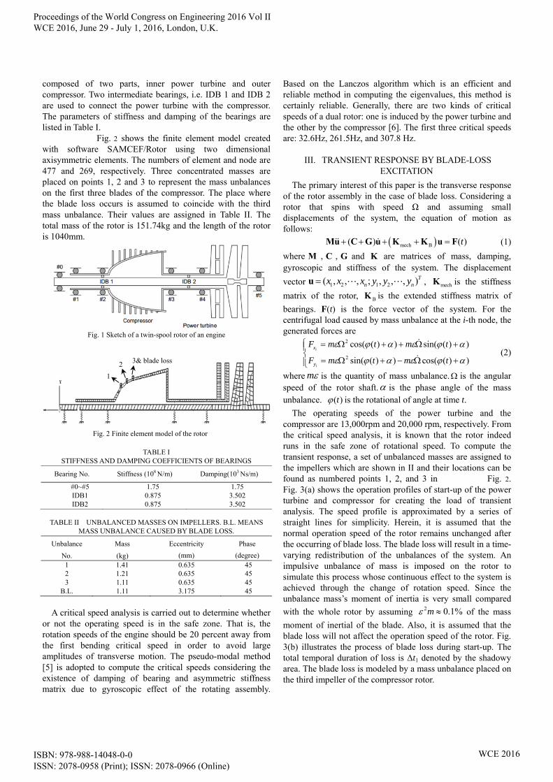
For investigation of transient response during the normal operations, it is assumed that the blade loss occurs at t=0.15s. Fig. 6 depicts the profile of rotational speed and the duration of the loss Δt2 denoted by the shadowy area. The parameters of mass unbalances are identical to the ones given in Table II.
Fig. 6 Blade loss profile during normal operation
(a) Profile of rotational speed (b) Blade loss at normal operation
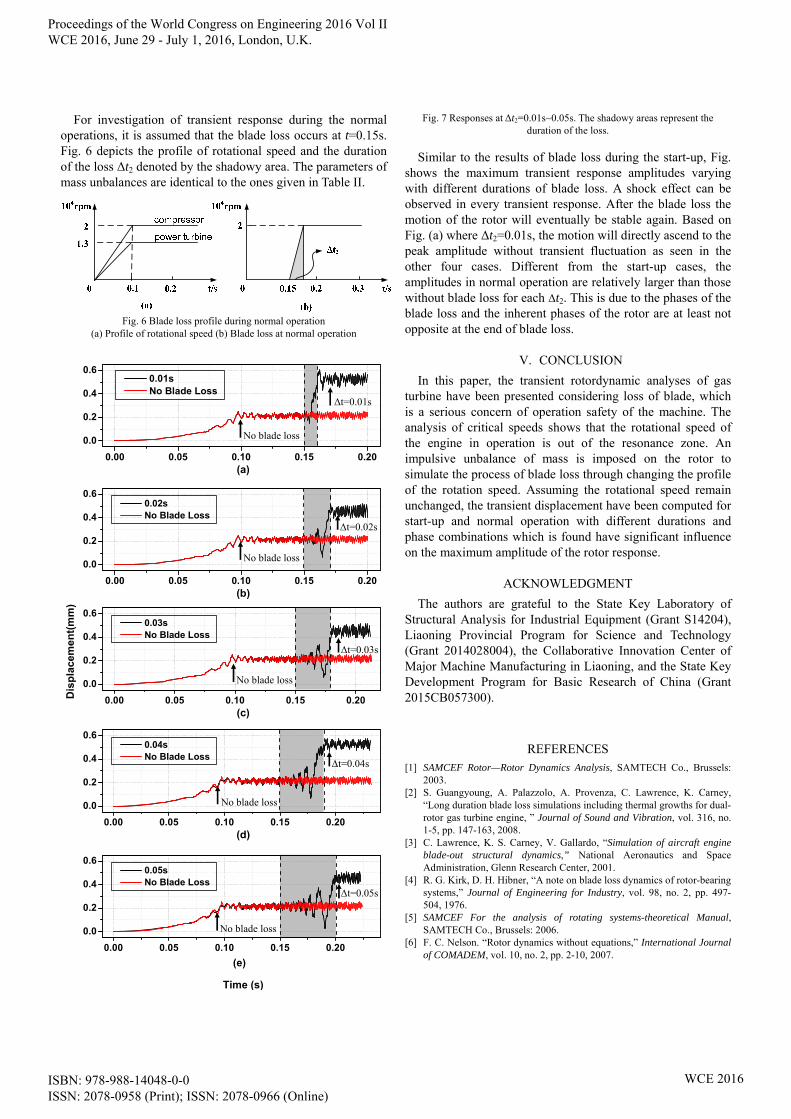
Fig. 7 Responses at Δt2=0.01s~0.05s. The shadowy areas represent the duration of the loss.
Similar to the results of blade loss during the start-up, Fig. shows the maximum transient response amplitudes varying with different durations of blade loss. A shock effect can be observed in every transient response. After the blade loss the motion of the rotor will eventually be stable again. Based on Fig. (a) where Δt2=0.01s, the motion will directly ascend to the peak amplitude without transient fluctuation as seen in the other four cases. Different from the start-up cases, the amplitudes in normal operation are relatively larger than those without blade loss for each Δt2. This is due to the phases of the blade loss and the inherent phases of the rotor are at least not opposite at the end of blade loss.
V. CONCLUSION
In this paper, the transient rotordynamic analyses of gas turbine have been presented considering loss of blade, which is a serious concern of operation safety of the machine. The analysis of critical speeds shows that the rotational speed of the engine in operation is out of the resonance zone. An impulsive unbalance of mass is imposed on the rotor to simulate the process of blade loss through changing the profile of the rotation speed. Assuming the rotational speed remain unchanged, the transient displacement have been computed for start-up and normal operation with different durations and phase combinations which is found have significant influence on the maximum amplitude of the rotor response.
ACKNOWLEDGMENT
The authors are grateful to the State Key Laboratory of Structural Analysis for Industrial Equipment (Grant S14204), Liaoning Provincial Program for Science and Technology (Grant 2014028004), the Collaborative Innovation Center of Major Machine Manufacturing in Liaoning, and the State Key Development Program for Basic Research of China (Grant 2015CB057300).
REFERENCES [1] SAMCEF Rotor—Rotor Dynamics Analysis, SAMTECH Co., Brussels:
2003. [2] S. Guangyoung, A. Palazzolo, A. Provenza, C. Lawrence, K. Carney,
“Long duration blade loss simulations including thermal growths for dual-rotor gas turbine engine, ” Journal of Sound and Vibration, vol. 316, no. 1-5, pp. 147-163, 2008.
[3] C. Lawrence, K. S. Carney, V. Gallardo, “Simulation of aircraft engine blade-out structural dynamics,” National Aeronautics and Space Administration, Glenn Research Center, 2001.
[4] R. G. Kirk, D. H. Hibner, “A note on blade loss dynamics of rotor-bearing systems,” Journal of Engineering for Industry, vol. 98, no. 2, pp. 497-504, 1976.
[5] SAMCEF For the analysis of rotating systems-theoretical Manual, SAMTECH Co., Brussels: 2006.
[6] F. C. Nelson. “Rotor dynamics without equations,” International Journal of COMADEM, vol. 10, no. 2, pp. 2-10, 2007.
0.00 0.05 0.10 0.15 0.20
0.0
0.2
0.4
0.6
0.00 0.05 0.10 0.15 0.20
0.0
0.2
0.4
0.6
0.00 0.05 0.10 0.15 0.20
0.0
0.2
0.4
0.6
0.00 0.05 0.10 0.15 0.20
0.0
0.2
0.4
0.6
0.00 0.05 0.10 0.15 0.20
0.0
0.2
0.4
0.6
(a)
0.01s No Blade Loss
(b)
0.02s No Blade Loss
Dis
pla
cem
ent(
mm
)
(c)
0.03s No Blade Loss
(e)
(d)
0.04s No Blade Loss
Time (s)
0.05s No Blade Loss
No blade loss
Δt=0.01s
Δt=0.02s
No blade loss
No blade loss
No blade loss
No blade loss
Δt=0.03s
Δt=0.04s
Δt=0.05s
Proceedings of the World Congress on Engineering 2016 Vol II WCE 2016, June 29 - July 1, 2016, London, U.K.
ISBN: 978-988-14048-0-0 ISSN: 2078-0958 (Print); ISSN: 2078-0966 (Online)
WCE 2016