Embed Size (px)
Citation preview
80000496 – Issue 3 10/18
DV250/DV300/DV400 Entro
Part No: 90000397/90000398/90000399
Use, maintenance and installation manual
2
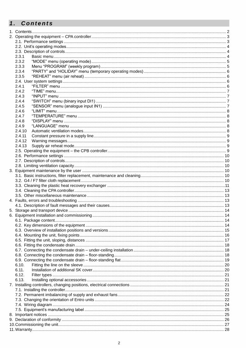
1 . C o n t e n t s
1. Contents .......................................................................................................................................................................... 2 2. Operating the equipment – CPA controller ...................................................................................................................... 3
2.1. Performance settings .............................................................................................................................................. 3 2.2. Unit’s operating modes ............................................................................................................................................ 4 2.3. Description of controls ............................................................................................................................................. 4 2.3.1 Basic menu ....................................................................................................................................................... 4 2.3.2 “MODE” menu (operating mode) ...................................................................................................................... 5 2.3.3 Menu “PROGRAM” (weekly program) .............................................................................................................. 5 2.3.4 “PARTY” and “HOLIDAY” menu (temporary operating modes) ........................................................................ 6 2.3.5 “REHEAT” menu (air reheat) ............................................................................................................................ 6 2.4. User system settings ............................................................................................................................................... 6 2.4.1 “FILTER” menu ................................................................................................................................................. 6 2.4.2 “TIME” menu ..................................................................................................................................................... 7 2.4.3 “INPUT” menu .................................................................................................................................................. 7 2.4.4 “SWITCH” menu (binary input DI1) .................................................................................................................. 7 2.4.5 “SENSOR” menu (analogue input IN1) ............................................................................................................ 7 2.4.6 “LIMIT” menu .................................................................................................................................................... 8 2.4.7 “TEMPERATURE” menu .................................................................................................................................. 8 2.4.8 “DISPLAY” menu .............................................................................................................................................. 8 2.4.9 “LANGUAGE” menu ......................................................................................................................................... 8 2.4.10 Automatic ventilation modes ............................................................................................................................. 8 2.4.11 Constant pressure in a supply line .................................................................................................................... 9 2.4.12 Warning messages ........................................................................................................................................... 9 2.4.13 Supply air reheat mode ..................................................................................................................................... 9 2.5. Operating the equipment – the CPB controller ........................................................................................................ 9 2.6. Performance settings ............................................................................................................................................ 10 2.7. Description of controls ........................................................................................................................................... 10 2.8. Limiting ventilation capacity ................................................................................................................................... 10
3. Equipment maintenance by the user ............................................................................................................................ 10 3.1. Basic instructions, filter replacement, maintenance and cleaning ......................................................................... 10 3.2. G4 / F7 filter cloth replacement ............................................................................................................................. 10 3.3. Cleaning the plastic heat recovery exchanger ....................................................................................................... 11 3.4. Cleaning the CPA controller ................................................................................................................................... 13 3.5. Other miscellaneous maintenance ........................................................................................................................ 13
4. Faults, errors and troubleshooting ................................................................................................................................ 13 4.1. Description of fault messages and their causes.................................................................................................... 13
5. Storage and transport device ........................................................................................................................................ 14 6. Equipment installation and commissioning ................................................................................................................... 14
6.1. Package content .................................................................................................................................................... 14 6.2. Key dimensions of the equipment ......................................................................................................................... 14 6.3. Overview of installation positions and versions ..................................................................................................... 15 6.4. Mounting the unit, fixing points .............................................................................................................................. 16 6.5. Fitting the unit, sloping, distances ......................................................................................................................... 17 6.6. Fitting the condensate drain .................................................................................................................................. 18 6.7. Connecting the condensate drain – under-ceiling installation ............................................................................... 18 6.8. Connecting the condensate drain – floor-standing ................................................................................................ 18 6.9. Connecting the condensate drain – floor-standing flat .......................................................................................... 19 6.10. Fitting the line on the sleeve ........................................................................................................................... 20 6.11. Installation of additional SK cover ................................................................................................................... 20 6.12. Filter types ...................................................................................................................................................... 21 6.13. Installing optional accessories ........................................................................................................................ 21
7. Installing controllers, changing positions, electrical connections .................................................................................. 21 7.1. Installing the controller........................................................................................................................................... 21 7.2. Permanent imbalancing of supply and exhaust fans ............................................................................................. 22 7.3. Changing the orientation of Entro units ................................................................................................................. 22 7.4. Wiring diagram ...................................................................................................................................................... 24 7.5. Equipment’s manufacturing label .......................................................................................................................... 25
8. Important notices .......................................................................................................................................................... 25 9. Declaration of conformity .............................................................................................................................................. 26 10. Commissioning the unit ................................................................................................................................................. 27 11. Warranty ........................................................................................................................................................................ 28

3
2 . O p e r a t i n g t h e e q u i p m e n t – C PA c o n t r o l l e r
The equipment operated using a CPA controller with touch-screen display.
Description of functions:
Controls are divided into user and servicing sections (accessible by service technicians only).
Ventilation capacity can be set in a range of 0-100 %.
Options to switch on the air reheater, air preheater and shut-off damper servo drive.
Control in manual mode or via separate weekly programs for ventilation capacity and air reheating.
Additional operating mode “Party” (a temporary increase in capacity) and “Holiday” (temporary ventilation switch-off).
An option to control ventilation automatically by external sensors (air quality, CO2, relative humidity etc.).
An option to start increased ventilation using external switches, e.g. in the bathroom or toilet.
An option to limit maximum and minimum ventilation capacity.
Displays the current room temperature and operating mode.
Alerts to the need for air filter replacement.
Display:
1. Time
2. Alerts (e.g. the need for filter replacement)
3. Date
4. Current room temperature
5. Air reheating indication (if the system includes areheater)
6. Ventilation capacity setting in %
7. Selected operating mode
Description of controls:
Short press – general controls and parameter settings
Long press (3s) of the ventilation capacity symbol – quick operation on / off
Long press (5s) at the top of the display – entering the service menu
2.1. Performance settings
When a CPA controller is used for controlling and programming, the capacity is shown (displayed) in per cents of the maximum. The table shows approximate air flow rates (m
3/h); they may vary depending on the duct network.
Entro Off 0 10% 20% 30% 40% 50% 60% 70% 80% 90% 100%
DV250 OFF Unit responds to
sensors and external inputs
20 35 95 120 155 180 200 220 240 250
DV300 OFF Unit responds to
sensors and external inputs
20 40 110 160 200 230 250 275 305 315
DV400 OFF Unit responds to
sensors and external inputs
30 50 140 200 260 300 320 350 380 400

4
2.2. Unit’s operating modes
The HVAC unit works according to settings made by the controller, external inputs from the bathroom, toilet or kitchen and air quality sensors in following modes:
2.3. Description of controls
The operating modes of the unit can be changed by selecting functions and parameters in the respective menus by using the touch-screen display.
The requested option (changing the function or parameter) in each menu must be confirmed by pressing the "OK" symbol or a symbol of "arrows" to move to the next menu. If you press the symbol "Esc", then the option is ignored and the system automatically returns to basic (Information) menu.
Note – in idle (display) state is the touch screen CPA glazed over, at the first touch automatically activates the backlight display, next touch can change particular functions (see description below).
2.3.1 Basic menu
Operating mode selection
Ventilation capacity selection or operation start / end
Switching on air reheating (if a reheater is installed in the system)
Displayed
mode Description
Suitable application
(data may vary depending on national regulations)
“Manual mode” – a general ventilation mode, with ventilation provided by the unit according to current settings.
Continuous ventilation during occupancy, with the capacity set at outside temperatures as follows:
Above approx. -5°C to approx. 25 m3/h/person, i.e. for
4 persons 100 m3/h, with 70 m
3/h set at night.
Below approx. -5°C to approx. 20 m3/h/person, i.e. for
4 persons 80 m3/h, with 50 m
3/h set at night.
“Weekly program” – a general ventilation mode, with a required rate of ventilation provided by the unit according to schedule parameters.
“Automatic mode” – the capacity of ventilation is set by an active external input, i.e. the user's request from the bathroom / toilet / kitchen or according to an air quality, CO2, humidity etc., if installed.
The unit switches over to these modes automatically if current ventilation demand exceeds the capacity set in manual mode or a weekly program.
“Ventilation run-down time” – a temporary ventilation mode which stops automatically after the pre-set time has elapsed.
The unit switches over to this mode automatically after a request from the bathroom / toilet / kitchen has expired (if a run-down time is set).
The “Party” mode is temporary and stops according to the pre-set time.
A temporary mode for less frequent use of the building, such as a party attended by a large number of people (a request for higher ventilation capacity).
The “Holiday” mode is temporary and stops according to the pre-set date and time; after that a weekly program is activated automatically.
A temporary mode for less frequent use of the building, such as a holiday (a unit deactivation request).

5
If operation is ended by setting ventilation capacity to “OFF”, the unit does not respond to an external request, i.e. switches in the bathroom / toilet / kitchen and the air quality sensor are ignored).
If power is set to "0 %", then the fans are stopped and the unit is not ventilating. In contrast to the "OFF" state, in this "0 %" mode is still active automatic start according to external switches.
Note – if none of buttons in submenus is pushed for a long period of time, then the CPA driver automatically switches to the main menu.
2.3.2 “MODE” menu (operating mode)
Selecting a weekly program / manual mode / Party mode / Holiday mode
If more than one parameter is shown in the menu, you can switch between these by a short press; a parameter can be set by pressing “+” and “-“ repeatedly (setting can be faster if you press and hold the symbol).
2.3.3 Menu “PROGRAM” (weekly program)
Setting a weekly program (time schedule) for ventilation capacity
Setting a weekly program for starting air reheat
Changes made in a weekly program for a selected period of Mon-Sun / Mon-Fri / Sat-Sun are effected in all selected days
together, while changes made for a period of Mon / Tue / Wed / Thu / Fri / Sat / Sun are effected only for the specific selected day.
Warning:
If one or more days of the week have been set individually, parameters for these individual days will be rewritten according to the new settings when a period of Mon-Sun / Mon-Fri / Sat-Sun is subsequently selected in adjustment mode (the pencil symbol).

6
2.3.4 “PARTY” and “HOLIDAY” menu (temporary operating modes)
Setting the required ventilation capacity of the “Party” mode in a range of 20 – 100 %
Setting the duration of the “Party” mode in a range between 10 minutes and 5 hours
Setting the time and date of ending the “Holiday” mode
After the “Party” mode has finished, the unit automatically returns to the operating mode selected before that; when the “Hol iday” mode has finished, the unit automatically switches over to operating mode which is current according to a weekly program.
Note – The “Party” and “Holiday” modes can be stopped early by selecting another operating mode.
2.3.5 “REHEAT” menu (air reheat)
Starting air reheat in manual mode
This menu is accessible only provided that an electric or hot-water air reheater is installed (selection in the service menu).
Information on air reheater operation is indicated in the basic menu by symbols and .
Note – Air reheating with an electric heater is only possible with a minimum ventilation capacity of 30 % due to a sufficient air flow rate for cooling the heating elements.
2.4. User system settings
Using directional arrows you can move between individual user menus:
MODE / VENTILATION / REHEAT / FILTER / TIME / SETTINGS
By pressing “OK” in the “SETTINGS” menu other parameter menus become accessible:
INPUT / SWITCH / SENSOR / SENSOR / LIMIT / TEMPERATURE / DISPLAY / FIRMWARE / LANGUAGE / LANGUAGE /
LANGUAGE
WARNING – The wrong parameter settings can have a negative influence on the proper operation of the equipment!
2.4.1 “FILTER” menu
Indication of the number of days left until the air filter must be replaced
Setting the regular filter replacement interval in a range of 30 – 150 days (by 10 day periods)
Filter replacement confirmation (a new countdown automatically starts after confirmation)
The regular filter replacement interval should be set according to the dust and pollen load of the outdoor environment.

7
2.4.2 “TIME” menu
Date and time setting
Selecting between 12 and 24 hour time format
Note – Automatic switching between summer and winter times (DST) is not supported.
2.4.3 “INPUT” menu
An option to allow / disallow the increased ventilation capacity function.
Binary input DI1 for connecting external voltage-free switches in bathrooms, toilets or kitchens.
An option to allow / disallow the function of automatic ventilation control according to the concentration of the quantity be ingmeasured.
Analogue input IN1 for connecting an external sensor (sensor “S“) with a 0-10V signal output which can monitor air quality, CO2 concentration, relative humidity etc.
2.4.4 “SWITCH” menu (binary input DI1)
Setting ventilation capacity in a range of 10 – 100 % with input DI1 closed
Setting a function’s start delay time in a range of 0 – 300 s (in 10 second steps)
Setting a function’s run-down time in a range of 0 – 300 s (in 10 second steps)
If a button is used the start delay time must be set to “0 s” in order for the short press of the button to be accepted, and the run-down time must be set to a non-zero value.
2.4.5 “SENSOR” menu (analogue input IN1)
Setting the ventilation curve in relation to the level of the 0-10V signal from an external sensor
This function allows suitably adjusting the unit’s response (ventilation capacity) to a gradual increase in the concentration of the quantity being measured, e.g. for economical or noise reasons.
The “inverse” setting of ventilation capacity response to the 0-10V control signal is also supported, i.e. the reverse direction of curve A-B).
This function allows connecting also a sensor with a different output voltage range, e.g. 0-5V or 2-10V.
8
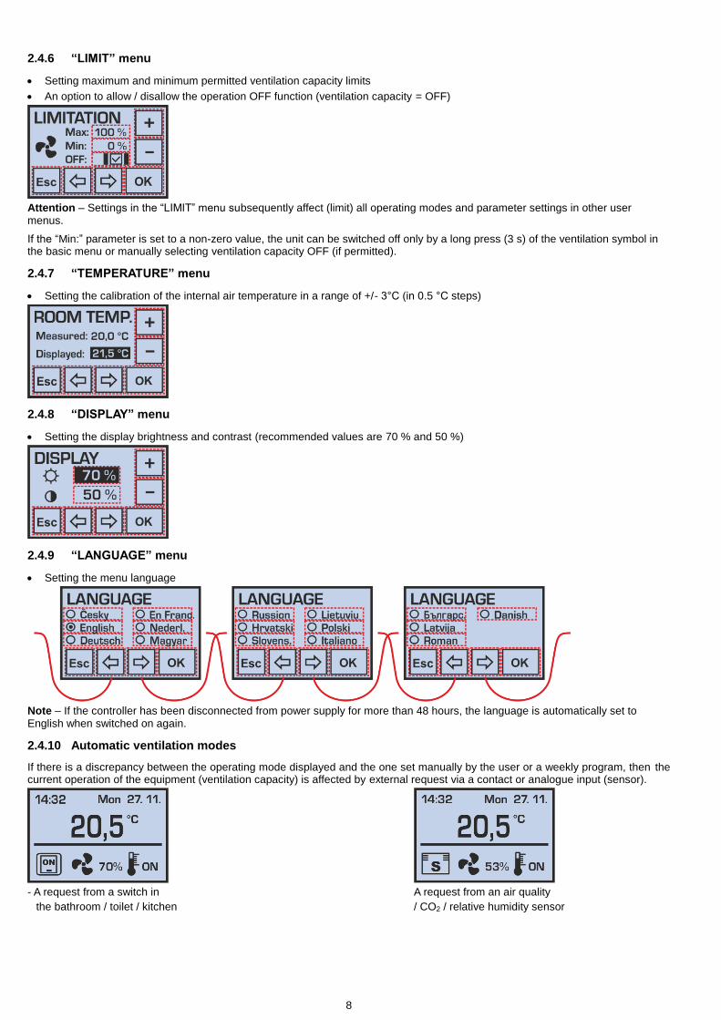
2.4.6 “LIMIT” menu
Setting maximum and minimum permitted ventilation capacity limits
An option to allow / disallow the operation OFF function (ventilation capacity = OFF)
Attention – Settings in the “LIMIT” menu subsequently affect (limit) all operating modes and parameter settings in other user menus.
If the “Min:” parameter is set to a non-zero value, the unit can be switched off only by a long press (3 s) of the ventilation symbol in the basic menu or manually selecting ventilation capacity OFF (if permitted).
2.4.7 “TEMPERATURE” menu
Setting the calibration of the internal air temperature in a range of +/- 3°C (in 0.5 °C steps)
2.4.8 “DISPLAY” menu
Setting the display brightness and contrast (recommended values are 70 % and 50 %)
2.4.9 “LANGUAGE” menu
Setting the menu language
Note – If the controller has been disconnected from power supply for more than 48 hours, the language is automatically set to English when switched on again.
2.4.10 Automatic ventilation modes
If there is a discrepancy between the operating mode displayed and the one set manually by the user or a weekly program, then the current operation of the equipment (ventilation capacity) is affected by external request via a contact or analogue input (sensor).
- A request from a switch in A request from an air quality
the bathroom / toilet / kitchen / CO2 / relative humidity sensor

9
2.4.11 Constant pressure in a supply line
If the unit is operated under constant pressure in the supply line (set in the service menu), then in the "FANS" and "PROGRAM" options are available: OFF / 0% / /
The symbols "sun" and "moon" are the two possible levels of pressure required, is standard operating (daily) pressure value, symbolizes the lower pressure value specified for night setback (e.g. due to noise).
This special mode in cooperation with the duct pressure sensor is able to provide automatic control of ventilation capacity by varying the number of ventilated rooms in the building (e.g. central ventilation of residential house)
Note – If a problem occurs during operation, the measurement of pressure in the supply line (e.g. due to pressure sensor failure), it is possible to cancel CS ("constant sensor") in the user menu "Inputs" and to deactivate ventilation on constant pressure.
Now you can control the fans performance standard way in manual mode or by setting a weekly program (see description in chapter 2.3.1 and 2.3.2).
2.4.12 Warning messages
The controller may display some warning messages during operation which alert to the need for replacing an air filter or flat battery; if the equipment has a defect, a warning message is shown recommending contacting the service department.
Replacing the controller's battery:
Before replacing the battery, disconnect the equipment from power supply!
Then use a tool such as a flat screwdriver to apply pressure onto "lock" on the bottom of the controller and remove the front panel with display. Now it is possible to replace the CR1632 battery and put the two parts of the controller back together. After turning it on it is necessary to set the correct time and date.
2.4.13 Supply air reheat mode
Only external EPO-PTC series duct electric air heaters, fitted with their own thermostat to set air temperature downstream the heater, can be connected to the equipment. Up to two such heaters may be connected simultaneously can be connected in the following configuration:
As a fresh air pre-heater (before the unit's inlet) The heater works fully automatically without being switching by the user, solely based on the temperature setting; this function (air preheating) only works when the unit is running.
As a reheater of air supplied into the building (it is located at the unit's outlet, downstream heat recovery) The heater is started by the user with the controller in manual mode or according to weekly program settings. The reheating function is only active when the unit is running.
Heaters must be fitted and connected according to the wiring diagram and only by a person with a relevant licence. Before the heater is put into operation, the temperature required downstream the heater must be set on the thermostat:
For a pre-heater: from 0 °C to +4 °C
For a reheater: between 10 and 35 °C
2.5. Operating the equipment – the CPB controller
As standard, the equipment is operated using a simple CPB controller.
Description of functions:
Ventilation capacity setting in a range of 0-100 %.
An option to start the air reheater.
An option to start the shut-off damper servo drive.
An automatic ventilation control option according to an external sensor (air quality, CO2, relative humidity etc.).

10
An option to increase ventilation capacity using external switches, e.g. in the bathroom or toilet.
An option to limit maximum and minimum ventilation capacity.
Equipment operation indication.
Description of controls:
1. Ventilation capacity setting
2. Signaling LED3. Operation indication
2.6. Performance settings
Identical to those the table in chapter 2.1. The HVAC unit operates according to settings by the controller, the closing of external inputs from the bathroom, toilet or kitchen, or an air quality sensor.
2.7. Description of controls
Selecting ventilation capacity or starting / stopping operation
- Rotate the controller to set the required ventilation capacity in a range of 10–100 %.- Ventilation is stopped by turning the controller anti-clockwise until it reaches the symbol "0" at the end position; however the
equipment still responds to external commands – see the chapter 3.3.
Starting air reheat
- The setting applies only provided that an external air heater with its own thermostat is fitted.- Start air reheat by pressing the button in the right hand bottom corner of the controller next to the thermometer symbol (stop by
pressing again)
Note:
- Air is reheated only when the unit is running.- The thermostat temperature is set by the technician in charge of installing the equipment in a range between 15 and 35 °C
2.8. Limiting ventilation capacity
Removing the rotary controller provides access to other control features, the turning of which sets the minimum and maximum ventilation capacity levels (a full range of 0-100 % is set by the manufacturer).
Description:
1. Setting of min. ventilation capacity
2. Setting of max. ventilation capacity
3 . E q u i p m e n t m a i n t e n a n c e b y t h e u s e r
3.1. Basic instructions, filter replacement, maintenance and cleaning
Maintenance involves visually checking the equipment, regularly replacing filters and cleaning the heat recovery exchanger.
During maintenance observe the rules of personal hygiene and use protective equipment (a face mask, packaging forcontaminated filters).
Before starting maintenance of the unit, always disconnect the equipment from power supply by unplugging the plug
from the power socket.
During maintenance observe safety instructions contained in the manual (“Important notice”), follow the fundamental rules ofsafe work and use suitable means of accessing HVAC equipment (ladders, stepladders).
3.2. G4 / F7 filter cloth replacement
You should replace the filter cloth only provided that you do not suffer from allergic reactions to dust particles. Do not conductreplacement when people with such a level of sensitivity are present.
Replace the filter cloth from the filter frame in a well-ventilated area or out of doors.
Before removing the frame with cloth, we recommend that you should have an air-tight bag (a plastic carrier bag etc.) ready tocarry the frame to a suitable area to conduct replacement and subsequently use it to dispose of the contaminated cloth, e.g. withcommon waste.
Replacement is carried out depending on the dust load of the ambient environment between every 500 and 2,000 operationhours (usually approx. 2 - 3 months). The recommended inspection interval is indicated on the controller's display.
Green - ON=> The unit's ventilation power matches the level set on the controllerRed - ON=> The pre-heater is running (if installed)Red - long-interval flashing=>The red LED is on for 0.3s and then off for 4.7s; this flashing indicates that filters must be replaced.Red - short-interval flashing=> The red LED is on for 0.1s and then off for 0.2s; this flashing indicates a controller fault - contact a service technician.

11
When replacing filters, do not remove the unit’s door – use the special cover for filter replacing.
Sliding the filter frame out of the unit and replacing the cloth
Release the filter plugs in the housing unit using the product in
the package – pull straight on
Do not pull on a slant!
Remove the cover on the unit’s enclosure
-start from the bigger recess
Take out the frame with filter cloth Slide a new filter cloth onto the frame - the fibre is to be slid onto the frame
Properly fitted cloth – the blue / red side faces the unit’s ports
and the white one the heat recovery exchanger
Fitting filter covers
-proceed from one side to another
Press the cover into the unit’s enclosure so that it is flush with the lid’s edge along the
entire perimeter
3.3. Cleaning the plastic heat recovery exchanger
The recommended interval of heat recovery exchanger cleaning is about 2 years, depending on the nature of the operating environment.
If necessary, wash the heat recovery exchanger block with warm water with a detergent several times; the water temperature should be up to 60 °C, ideally such that you could keep your hands in it comfortably (e.g. BODE Kohrsolin FF).
Do not expose the heat recovery exchanger to ultraviolet light and sunlight; store it in a dark place if necessary.
ATTENTION: Never use cleaning agents that might contain organic solvents to clean the heat recovery exchanger as they
could cause its irreversible damage!

12
Removing the heat recovery exchanger
Disconnect the unit from power supply, disconnect the condensate drain in ceiling units, open the unit and unlock the heat recovery exchanger on both sides.
Note down the position of the heat exchanger (the number depends on the equipment type) for seal fitting. The sticker with letter A must be by the edge of the fan enclosure.
Remove the cover and unscrew the locking screws from the unit's lid – 4 in the corners
Remove metal elements Open the unit’s door carefully and gradually from one side. Start from the wiring entry side. With in-ceiling units, disconnect the condensate drain.
When lifting the lid from the top of locks hanging from the other side of the lid.
Remove the metal grills on both sides of the heat exchanger
Remove the screw and loosen the metal grill.
Unlock the butterfly nut on one side of the exchanger Eject block recovery exchanger
Follow the procedure in reverse to slide the heat recovery exchanger back in. Before sliding exchangers in, we recommend lubricating only the seal with silicon oil for easy sliding and increasing the flexibility and life span of the seal.
Side A

13
3.4. Cleaning the CPA controller
The CPA controller requires the same maintenance as the lighting switch – cleaning is only possible using a dry cloth; no water may
enter the inside of the controller. Liquids which might damage its surface must not be used for its cleaning (e.g. organic
solvents).
3.5. Other miscellaneous maintenance
Before any intervention with the unit it must be disconnected from power supply!
During filter cloth or cassette replacement and every time you are opening the unit check the following:
The condensate drain in the unit's door or bottom for cleanliness.
Any blockage of the condensate drain might cause serious trouble.
The water level in the condensate drain, especially in summer and autumn. If the level is not high enough, air from the sewer might be drawn in; flood the condensate drain. If any parts of the equipment are covered in dust, clean them with a slightly damp cloth.
4 . F a u l t s , e r r o r s a n d t r o u b l e s h o o t i n g
4.1. Description of fault messages and their causes
Fault Description Possible cause Troubleshooting
The equipment
cannot be started The equipment
remains idle even after the required performance level was selected
Power supply is not connected Connect the equipment to power supply (switch on upstream safety circuit breakers)
Not found Disconnect from power supply and contact a service technician
The equipment is
not supplying
enough air
The equipment is providing a significantly lower volume of air
Blocked filter Disconnect the equipment from
power supply
Replace the filter cloth or cassette
If the equipment has been in operation for more than approx. 4 years, clean the heat recovery exchanger/s
A mechanical obstacle at fresh air suction or supply air outlets
Check whether the suction openings of fresh air or supply air outlets are not mechanically covered
Remove any obstacles
Visually and by listening check whether the dampers open properly
Not found Disconnect from power supply and contact a service technician
The equipment is
not heating or is
heating
insufficiently
When the heater has been started, supply air continues to be cold
The electric heater is not connected to power supply
Connect the equipment to power supply (switch on upstream safety circuit breakers) – can only be done by an authorized person
Response of the electric heater’s heat protection
Wait to see if the fault does not sort itself out after approx. 1 hour
Low maximum capacity of the heater
Does not constitute a fault (insufficient capacity designed)
Not found Disconnect from power supply and contact a service technician
Water is dripping
from the
equipment
Water droplets form between the door and body of the equipment during operation
The condensate drain siphon is insufficiently flooded
Disconnect the equipment from
power supply and flood the condensate drain siphon
The condensate drain is blocked with dirt
Disconnect the equipment from
power supply and clean the condensate drain including the siphon
The seal groove is damaged (the fault can be accompanied by a whistling sound caused by air flowing through the gap)
Disconnect the equipment from
power supply and replace the seal
Water droplets form at the condensate drain connection point
The condensate drain seal or line is damaged
Disconnect the equipment from
power supply and re-seal the condensate drain
Not found Disconnect from power supply and contact a service technician

14
5 . S t o r a g e a n d t r a n s p o r t d e v i c e
During transport and storage the prescribed position indicated by the sticker on the box must be observed!
The equipment may only be stored in dry, clean places with ambient temperatures between 0 °C and 50° C. Up to 7 units may be stored horizontally. The equipment must be placed on a flat, hard surface to avoid damaging it or its packaging.
During storage the equipment must be kept in its original, intact packaging including all spacing, tightening and indicating elements.
The transport packaging may not be removed until the unit has been delivered at the site of final installation. All parts which are to come into contact with flowing air must be checked for cleanliness and cleaned if necessary before installation.
If the equipment is to be handled using a forklift or palette truck, it must be placed on a transport EUR pallet.
During transport the equipment must be protected against any falls, mechanical damage, water leaks and any other adverse effects that could damage the equipment or its packaging.
6 . E q u i p m e n t i n s t a l l a t i o n a n d c o m m i s s i o n i n g
6.1. Package content
The basic package of Entro units contains the following accessories:
The operation, maintenance and installation manual
An abridged control manual
A CPA controller connected, with a 230 V power supply plug (with a connecting cable length of 3 lm).
Plastic components for connecting the condensate drain line
2 pcs of condensate drain installation kits for floor-standing and floor-standing flat positions (a bushing, seals, nuts)
A mounting kit for fixing the unit (a high nut, 2 washers, a hexagonal screw, a plastic cover).
6.2. Key dimensions of the equipment
DV250 Entro DV300 Entro DV400 Entro Dimensions
W mm 850 850 850
H mm 660 820 820
D mm 280 280 280 Ports
e1 mm 160 160 160
e2 mm 160 160 160
i1 mm 160 160 160
i2 mm 160 160 160
Weight kg 20 21 21
Condensate drains mm 2 x ø 14 (prepared for 4 more)
Fixing mm 4 x Ø8 4 x Ø8 4 x Ø8
15
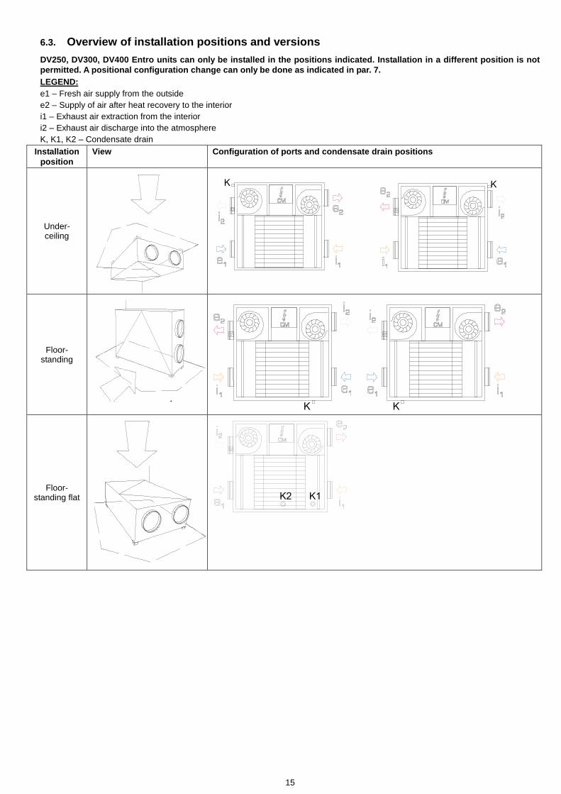
6.3. Overview of installation positions and versions
DV250, DV300, DV400 Entro units can only be installed in the positions indicated. Installation in a different position is not
permitted. A positional configuration change can only be done as indicated in par. 7.
LEGEND:
e1 – Fresh air supply from the outside
e2 – Supply of air after heat recovery to the interior
i1 – Exhaust air extraction from the interior
i2 – Exhaust air discharge into the atmosphere
K, K1, K2 – Condensate drain
Installation
position
View Configuration of ports and condensate drain positions
Under-ceiling
PODSTROPNÍ
PODLAHOVÁ
PARAPETNÍ
K
KK
K K
PODSTROPNÍ
PODLAHOVÁ
PARAPETNÍ
K
KK
K K
Floor-standing
PODSTROPNÍ
PODLAHOVÁ
PARAPETNÍ
K
KK
K K
PODSTROPNÍ
PODLAHOVÁ
PARAPETNÍ
K
KK
K K
Floor-standing flat
PODSTROPNÍ
PODLAHOVÁ
PARAPETNÍ
K
KK
K K
K1K2
16
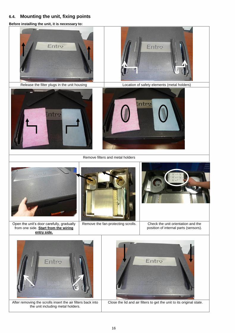
6.4. Mounting the unit, fixing points
Before installing the unit, it is necessary to:
Release the filter plugs in the unit housing Location of safety elements (metal holders)
Remove filters and metal holders
Open the unit’s door carefully, gradually
from one side. Start from the wiring
entry side.
Remove the fan-protecting scrolls.
Check the unit orientation and the position of internal parts (sensors).
After removing the scrolls insert the air filters back into the unit including metal holders.
Close the lid and air filters to get the unit to its original state.

17
Anchoring points
DV250 Entro
DV300 Entro, DV400 Entro 4xO9
805
775
280
618
4xO9
280805
4xO9
805
775
280
618
4xO9
280805
Anchoring detailed view
1. 1.Entro unit
2. 2.Threaded rod M8 – NOT INCLUDED
3.Wall / ceiling anchor – NOT INCLUDED
3. 4.DIN 9021 M8 washer – INCLUDED
4. 5.DIN 6334 M8 nut – INCLUDED
5. 6.ISO 7380 M8 screw – INCLUDED
6. 7.Plastic cover – INCLUDED
6 . 5 . F i t t i n g t h e u n i t , s l o p i n g , d i s t a n c e s
If the unit is installed to ventilate a general use indoor environment, its interior design (only for floor-standing and under-ceiling installation) ensures the transport of condensate to the required point without the need for additionally sloping the unit.
For all positions it is necessary to keep the unit slope towards the condensate outlet. Recommended sloping of the unit is:
- 3 % (25 mm) for Floor-standing and under-ceiling position
- 10 % and 12 % (75 mm and 100 mm) for Floor-standing flat position
To achieve acceptable acoustic values it is necessary to install air distribution with guaranteed acoustic attenuation. The
minimum distance of the nearest outlet from the ventilation unit in the supply line (behind supply fan) is 2-3 m. The line
before the first diffuser must be done with noise attenuation - fixed or flexible distribution silencer with sound dampening
insulation.
Under-ceiling Floor-standing Floor-standing flat

18
Recommended distances
min. 250
min. 75
min. 350min. 350
6.6. Fitting the condensate drain
The unit must have a condensate drain fitted in exhaust air outlet section i2 – see paragraph 6.3.
Condensate drains not in use must remain sealed.
The condensate drain line must be connected so that it does not get damaged during handling the unit. In under-ceiling
installation the condensate drain must be disconnected before opening the door of the unit.
For the position condensate drain in various configurations of ports see paragraph 6.3. – must be observed.
6.7. Connecting the condensate drain – under-ceiling installation
A condensate drain outlet from the door in section i2, with condensate drain accessories
Connecting the condensate drain with a 90°elbow and
connecting the line
Inserting the line and securing it with a clip (the clip and the line is provided by
the plumbing installation company)
Connecting a straight condensate drain with
a sleeve to connect the line
Inserting the line and securing it with a clip (the clip and the line
is provided by the plumbing installation company)
6.8. Connecting the condensate drain – floor-standing
When the unit is to be installed in a floor-standing position, a condensate drain must be first prepared using the bushing provided and silicon. All this must be done before putting the unit into operation; the equipment must be disconnected from power supply.
To install the condensate drain use only the points provided on the units in the form of visible recesses.
Holes for the fitting kit are provided and needn’t be cut out - just push out the plug being pushed out.
Fitting the bushing into the unit’s enclosure
Fitting
19
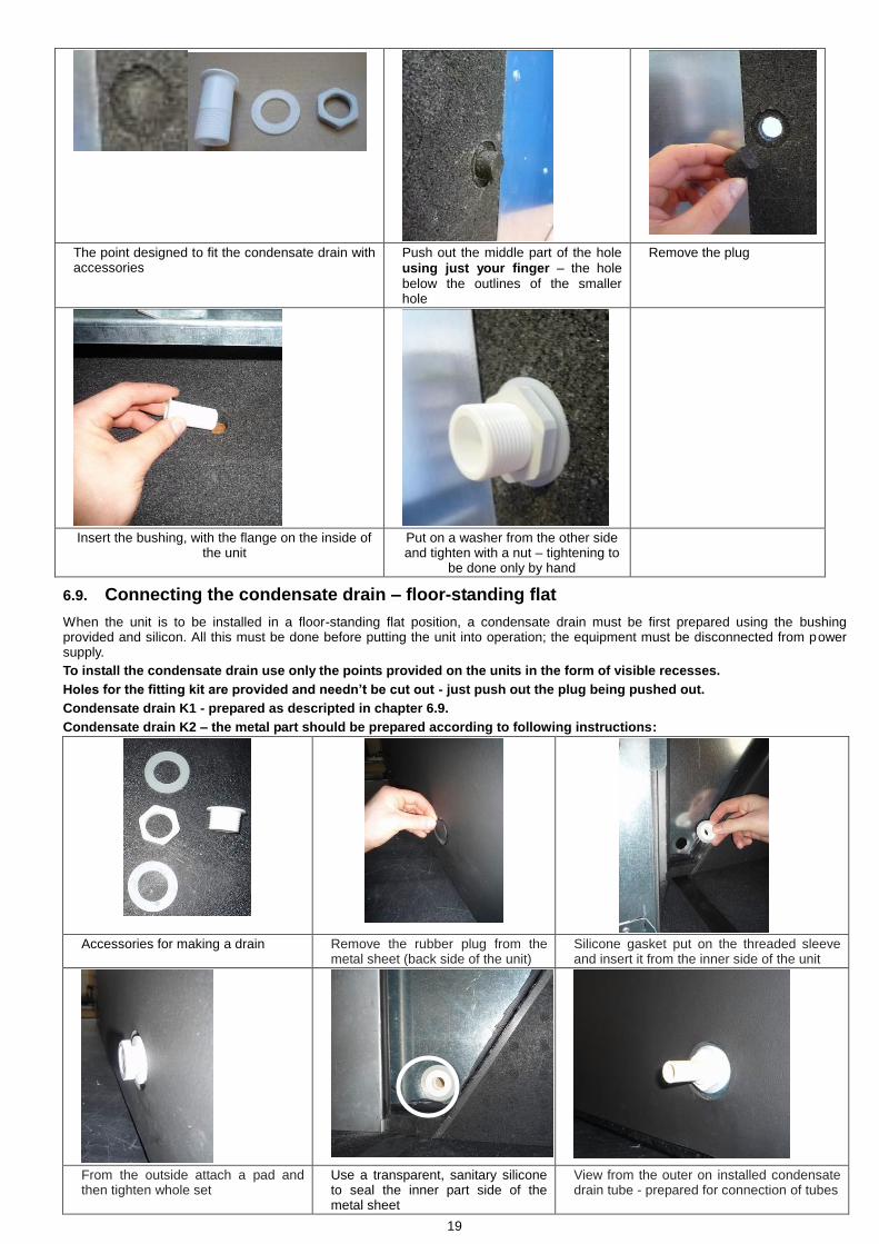
The point designed to fit the condensate drain with accessories
Push out the middle part of the hole
using just your finger – the hole below the outlines of the smaller hole
Remove the plug
Insert the bushing, with the flange on the inside of the unit
Put on a washer from the other side and tighten with a nut – tightening to
be done only by hand
6.9. Connecting the condensate drain – floor-standing flat
When the unit is to be installed in a floor-standing flat position, a condensate drain must be first prepared using the bushing provided and silicon. All this must be done before putting the unit into operation; the equipment must be disconnected from power supply.
To install the condensate drain use only the points provided on the units in the form of visible recesses.
Holes for the fitting kit are provided and needn’t be cut out - just push out the plug being pushed out.
Condensate drain K1 - prepared as descripted in chapter 6.9.
Condensate drain K2 – the metal part should be prepared according to following instructions:
Accessories for making a drain Remove the rubber plug from the metal sheet (back side of the unit)
Silicone gasket put on the threaded sleeve and insert it from the inner side of the unit
From the outside attach a pad and then tighten whole set
Use a transparent, sanitary silicone to seal the inner part side of the metal sheet
View from the outer on installed condensate drain tube - prepared for connection of tubes
20
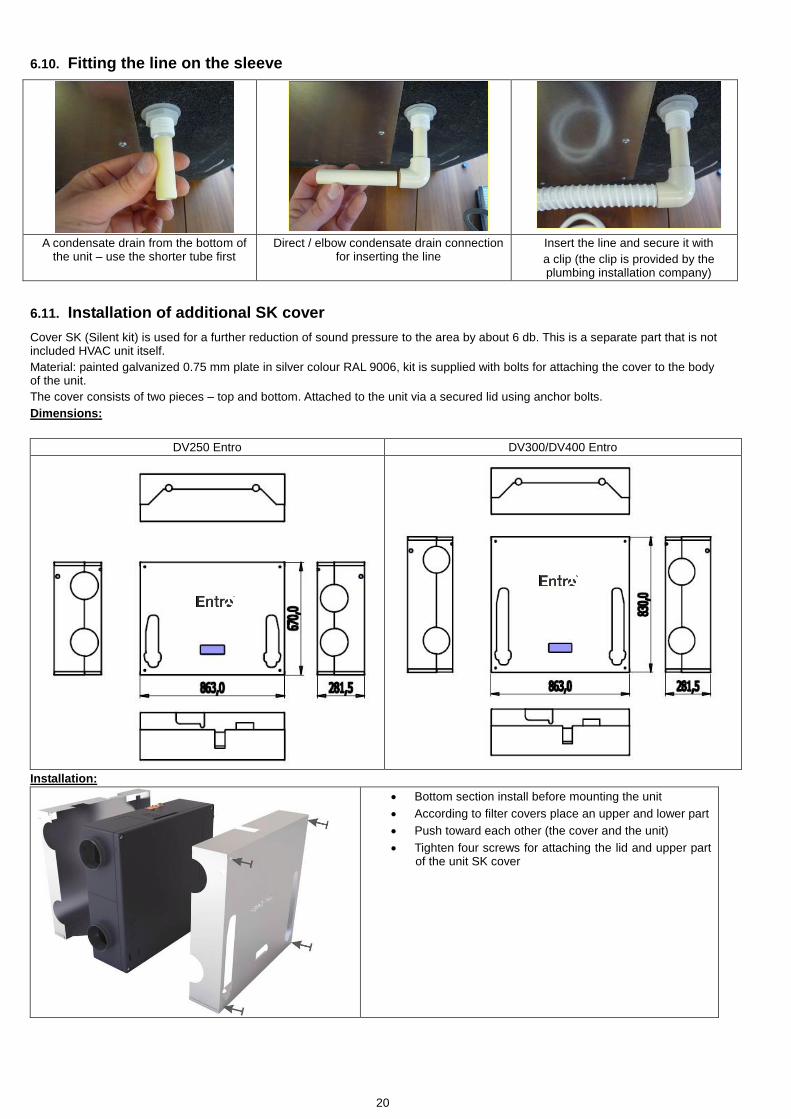
6.10. Fitting the line on the sleeve
A condensate drain from the bottom of the unit – use the shorter tube first
Direct / elbow condensate drain connection for inserting the line
Insert the line and secure it with
a clip (the clip is provided by the plumbing installation company)
6.11. Installation of additional SK cover
Cover SK (Silent kit) is used for a further reduction of sound pressure to the area by about 6 db. This is a separate part that is not included HVAC unit itself.
Material: painted galvanized 0.75 mm plate in silver colour RAL 9006, kit is supplied with bolts for attaching the cover to the body of the unit.
The cover consists of two pieces – top and bottom. Attached to the unit via a secured lid using anchor bolts.
Dimensions:
DV250 Entro DV300/DV400 Entro
Installation:
Bottom section install before mounting the unit
According to filter covers place an upper and lower part
Push toward each other (the cover and the unit)
Tighten four screws for attaching the lid and upper part of the unit SK cover

21
6.12. Filter types
The basic version of the equipment is supplied with a Class G4 filter cloth in a stainless frame, with a Class F7 cloth available as an optional extra.
6.13. Installing optional accessories
The following external pre-heaters or reheaters can be connected to the unit:
An EPO-PTC external air pre-heater on the supply fresh air route to the unit.
An EPO-PTC external air reheater on the exhaust air route to the building.
A manual for fitting, connecting and wiring these external appliances is supplied along with them.
For necessary settings see paragraph 2.3.
Other than the above types of electric heaters are not permitted for use with Entro units!!!
7 . I n s t a l l i n g c o n t r o l l e r s , c h a n g i n g p o s i t i o n s , e l e c t r i c a l c o n n e c t i o n s
7.1. Installing the controller
A CPA touch-screen controlled providing full control and programming is connected as standard. It is supplied for installation on the wall and can be fitted into a recessed installation box.
The controller should be mounted on the wall at a height of 1.3 – 1.5 metres at an easily accessible, well-lit and dry place, not close to heaters and heat radiating surfaces.
Included is a low-current shielded connecting cable (SYKFY 5x2x0.5) 3 metres long. When the controller is required to be further away from the ventilation unit, the cable must be replaced / extended (up to 25 metres).The controller must be installed by a specialized installation company’s technician.
Warning: Before installing or removing the controller disconnect the unit from power supply. Handling the controller with
power left on might lead to electrocuting or damage the controller.
CPA Installation on the wall
Spare filter cloths – packaging, optional accessory
Filter frame with filter cloth
22
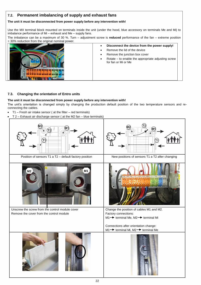
7.2. Permanent imbalancing of supply and exhaust fans
The unit it must be disconnected from power supply before any intervention with!
Use the MX terminal block mounted on terminals inside the unit (under the hood, blue accessory on terminals Me and Mi) to imbalance performance of Mi – exhaust and Me – supply fans.
The imbalance can be a maximum of 30 %. Turn – adjustment screw is reduced performance of the fan – extreme position = 30% reduction from the original nominal power.
Disconnect the device from the power supply!
Remove the lid of the device
Remove the junction box cover
Rotate – to enable the appropriate adjusting screw for fan or Mi or Me
7.3. Changing the orientation of Entro units
The unit it must be disconnected from power supply before any intervention with!
The unit’s orientation is changed simply by changing the production default position of the two temperature sensors and re-connecting the cables.
T1 – Fresh air intake sensor ( at the filter – red terminals)
T 2 – Exhaust air discharge sensor ( at the M2 fan – blue terminals)
Position of sensors T1 a T2 – default factory position
New positions of sensors T1 a T2 after changing
Unscrew the screw from the control module cover
Remove the cover from the control module
Change the position of cables M1 and M2.
Factory connections:
M1 terminal Me, M2 terminal Mi
Connections after orientation change:
M1 terminal Mi, M2 terminal Me
M1 M2
23
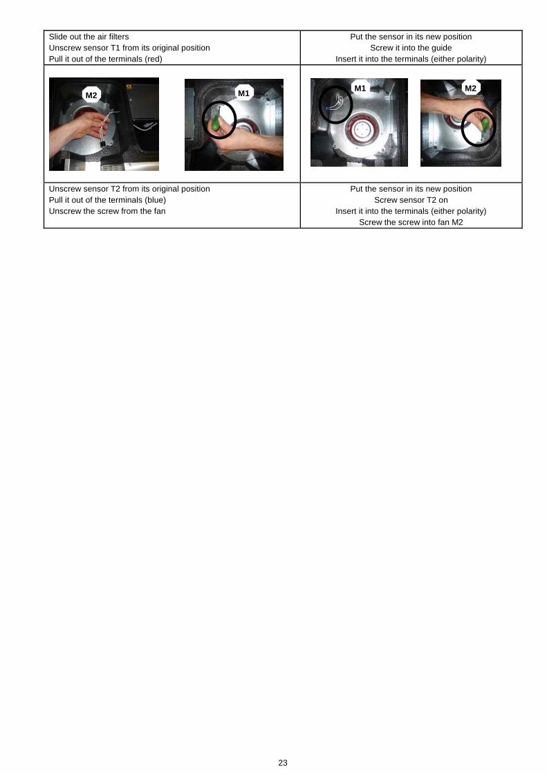
Slide out the air filters
Unscrew sensor T1 from its original position
Pull it out of the terminals (red)
Put the sensor in its new position
Screw it into the guide
Insert it into the terminals (either polarity)
Unscrew sensor T2 from its original position
Pull it out of the terminals (blue)
Unscrew the screw from the fan
Put the sensor in its new position
Screw sensor T2 on
Insert it into the terminals (either polarity)
Screw the screw into fan M2
M2 M2 M1
M1
24
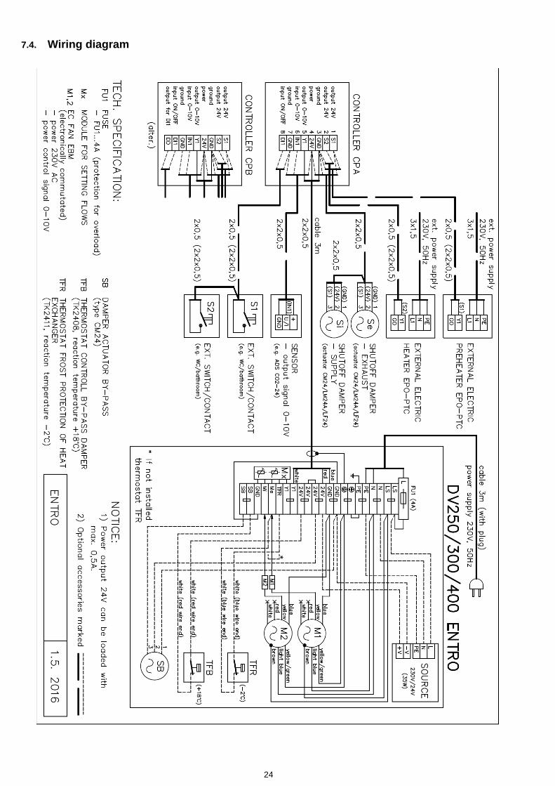
7.4. Wiring diagram
25
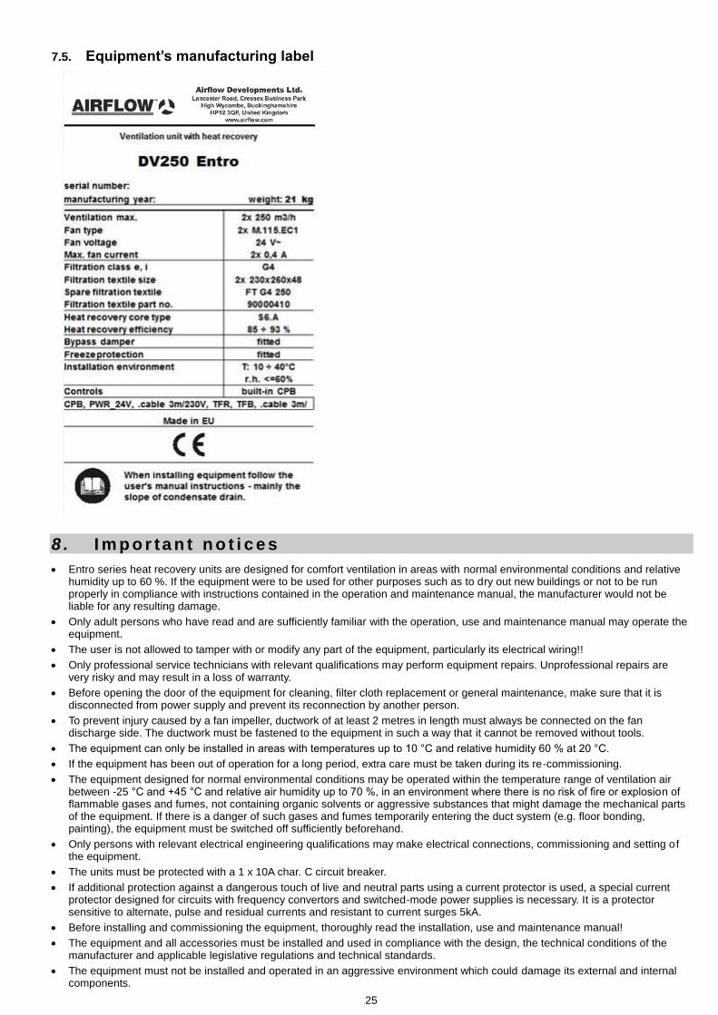
7.5. Equipment’s manufacturing label
8 . I m p o r ta n t n o t i c e s
Entro series heat recovery units are designed for comfort ventilation in areas with normal environmental conditions and relative humidity up to 60 %. If the equipment were to be used for other purposes such as to dry out new buildings or not to be run properly in compliance with instructions contained in the operation and maintenance manual, the manufacturer would not be liable for any resulting damage.
Only adult persons who have read and are sufficiently familiar with the operation, use and maintenance manual may operate the equipment.
The user is not allowed to tamper with or modify any part of the equipment, particularly its electrical wiring!!
Only professional service technicians with relevant qualifications may perform equipment repairs. Unprofessional repairs are very risky and may result in a loss of warranty.
Before opening the door of the equipment for cleaning, filter cloth replacement or general maintenance, make sure that it is disconnected from power supply and prevent its reconnection by another person.
To prevent injury caused by a fan impeller, ductwork of at least 2 metres in length must always be connected on the fan discharge side. The ductwork must be fastened to the equipment in such a way that it cannot be removed without tools.
The equipment can only be installed in areas with temperatures up to 10 °C and relative humidity 60 % at 20 °C.
If the equipment has been out of operation for a long period, extra care must be taken during its re-commissioning.
The equipment designed for normal environmental conditions may be operated within the temperature range of ventilation air between -25 °C and +45 °C and relative air humidity up to 70 %, in an environment where there is no risk of fire or explosion of flammable gases and fumes, not containing organic solvents or aggressive substances that might damage the mechanical parts of the equipment. If there is a danger of such gases and fumes temporarily entering the duct system (e.g. floor bonding, painting), the equipment must be switched off sufficiently beforehand.
Only persons with relevant electrical engineering qualifications may make electrical connections, commissioning and setting of the equipment.
The units must be protected with a 1 x 10A char. C circuit breaker.
If additional protection against a dangerous touch of live and neutral parts using a current protector is used, a special current protector designed for circuits with frequency convertors and switched-mode power supplies is necessary. It is a protector sensitive to alternate, pulse and residual currents and resistant to current surges 5kA.
Before installing and commissioning the equipment, thoroughly read the installation, use and maintenance manual!
The equipment and all accessories must be installed and used in compliance with the design, the technical conditions of the manufacturer and applicable legislative regulations and technical standards.
The equipment must not be installed and operated in an aggressive environment which could damage its external and internal components.

26
Before putting the equipment into permanent operation, an initial inspection report for the equipment’s power supply must be provided.
In the event of a defect the equipment must be immediately disconnected from power supply!
During the installation and handling of the equipment observe all rules of safe work, including safe work in heights and work with suspended loads, and use suitable protective equipment.
During installation make sure the equipment’s enclosure does not get damaged or deformed.
9 . D e c l a r a t i o n o f c o n f o r m i t y
The manufacturer is not liable for damage caused by improper installation which fails to observe the
installation manual and common practice in installing HVAC units and control systems.

27
1 0 . C o m m i s s i o n i n g t h e u n i t
The Building Regulations 2010, Statutory Instrument Part 9, paragraph 42, imposes a requirement that testing and reporting of mechanical ventilation performance is conducted in accordance with an approved procedure.
Compliance with this requirement by an assessed and registered ‘Competent Person’ should follow a ‘Best Practice’ process and adopt air flow measurement, Method A – The Unconditional Method – using a suitable UKAS certified measuring instrument. Generically referred to as a ‘Zero Pressure Air Flow Meter’ or ‘Powered Flow Meter’.
Further information on this method is detailed in NHBC Building Regulations Guidance Note G272a 10/13 and BSRIA ‘A Guide to Measuring air flow rates’ document BG46/2015

28
1 1 . Wa r r a n t y
The product has a warranty period of two years. *The warranty can be upgraded to THREE years from the date of purchase against faulty material or workmanship by registering on our website:
www.airflow.com
The warranty only covers the product and not the installation cost.
In case such a fault in the manufacture becomes apparent during the warranty period, Airflow may, at its absolute discretion, repair the product free of charge or refund the cost of the product as long as and only if:
1. The product is returned within the Guarantee Period with evidence of purchase date
2. The product has not been misused or handled carelessly or used on an inappropriate voltage supply
3. Repairs have not been attempted other than by Airflow’s service staff or
4. In Airflow’s sole discretion, the product is found to be faulty. If it were not found to be faulty, the product would be availablefor collection from the relevant Airflow premises within one calendar month and if it was not collected, it would besubsequently delivered by Airflow and a delivery charge will be made.
5. Has been installed in accordance with the latest Building Regulations and IEE Wiring Regulations.
This warranty does not confer any rights other than those expressly set out above and does not cover any claims for consequential loss, damage or any costs incurred in the replacement of the faulty product.
This warranty is offered as an extra benefit and does not affect your statutory right as a consumer.
All information believe correct at time of going to press.
All goods are sold according to Airflow Developments Limited’s Standard Condition of Sale which is available on request.
In the interest of continuous development, Airflow Developments Limited continuously strives to improve their products and reserve the right to change specifications and prices without prior notice.
* excludes motors. Motor warranty one year from date of purchase.
Airflow Developments Limited
Aidelle House, Lancaster RoadCressex Business Park, High Wycombe
Buckinghamshire, HP12 3QP, U.K
E: [email protected]: 44 (0) 1494 525252W: airflow.com
©Copyright 2016. Airflow Developments Ltd