Embed Size (px)
Citation preview
Dust barriers in open pit blasts. Multiphase Computational Fluid Dynamics (CFD) simulations J. T. Alvarez, I. D. Alvarez & S. T. Lougedo GIMOC, Mining Engineering and Civil Works Research Group, Oviedo School of Mines, University of Oviedo, Spain
Abstract
In the framework of the Research Project CTM2005-00187/TECNO, “Prediction models and prevention systems in the particle atmospheric contamination in an industrial environment” of the Spanish National R+D Plan of the Ministry of Education and Science, 2004-2007 period, there has been developed a CFD model to simulate the dispersion of the dust generated in blasts located in limestone quarries. The possible environmental impacts created by an open pit blast are ground vibrations, air shock waves, flying rocks and dust dispersion, being this last effect the less studied one. This is a complex phenomenon that was studied in previous successful researches through the use of several digital video recordings of blasts and the dust concentration field data measured by light scattering instruments, as well as the subsequent simulation of the dust clouds dispersion using Multiphase Computational Fluid Dynamics (CFD). CFD calculations where done using state of the art commercial software, Ansys CFX 10.0, through transitory models simultaneously using 7 different dust sizes with Lagrangian particle models crossing an Eulerian air continuous phase. This paper presents results and observations obtained through repeated simulations that virtually install physical barriers in the vicinity of the blast with the aim of diminishing the dust cloud dispersion ant the associated environmental impact. There have been tested several combinations of low and high barriers installed 100 or 200 m apart from the blasting area. Assuming full trapping of the dust in the solid barrier there are scenarios where dust retention in the model could be as high as 90%, which shows the potential use of barriers to avoid dust dispersion. Models also show the barriers shadow effect in the dust deposition area, useful for the definition of protection areas where sensible equipment or installation could be located. Keywords: bench blasting, dust dispersion modelling, CFD, multiphase, discrete Lagrangian methods, dust barriers.
www.witpress.com, ISSN 1743-3541 (on-line)
© 2008 WIT PressWIT Transactions on Ecology and the Environment, Vol 116,
Air Pollution XVI 85
doi:10.2495/AIR080101
1 Introduction
Our research group is developing a project named CTM2005-00187/TECNO, “Prediction models and prevention systems in the particle atmospheric contamination in an industrial environment” granted by funds of the Spanish National R+D Plan of the Ministry of Education and Science, 2004-2007 period. Within the research objectives appears one relating to the determination of the amount of dust produced in a blast and its immersion in the atmosphere surrounding the quarry area by means of two main tools: measurement campaigns of the dust concentration using “Light scattering” dust sensors and computerized simulations through commercial CFD (Computational Fluid Dynamics) software. These are done through the combined use of Solidworks to generate the 3D models, ICEM CFD to adequately mesh the domain and Ansys CFX 10.0 in case of the calculation and analysis of the results. There are dozens of methods to simulate the dust dispersion in open areas [1] and authors as Reed [2] have studied their application in dust generated in mining and civil works. The authors have validated the use of CFD in order to simulate the dust movement both using CFD [3] and using more conventional dispersion models as ISC3 [4]. ISC3 allows the simulation of dust movement in large physical areas and time schedules but fails in the short range. CFD is the perfect method to simulate complicated geometrical configurations where wind and dust interact and then will be used to develop the simulations explained in this paper. This paper will show simulations done where solid barriers 3 m and 20 m height are virtually installed in the vicinity of the quarry bench in order to evaluate their ability to trap the dust particles. Authors such as Cowherd and Grelinger [5] have made experiences in dust emitting roads surrounded by several species of trees and have observed diminishing in the dust levels due to their presence. The same phenomenon has to occur in a quarry bench configuration.
2 Previous studies and simulations
After detailed analysis of the topography of the quarry and the photographs and digital video recordings of the blast a 3D geometry model was developed using the parametric software Solidworks. The simulated domain ranges 400x500x250 m including a 18 m height and 15º slope bench followed by a plain area where the measuring instrumentation was located, surrounded in the left side by a hill. The blast was not only recorded in digital video but was also measured with dust concentration measurement equipment. The instrumentation sensed a peak level of 700 µg/m3 in case of the dust sensor located at 100 meters from the blast and 200 µg/m3 in case of the dust sensor located at 200 meters. The meteorological conditions were 24ºC of temperature, 1015 mb of pressure, 2.5 m/s of sustained wind velocity, humidity of 55%, sunny day and null rain.
www.witpress.com, ISSN 1743-3541 (on-line)
© 2008 WIT PressWIT Transactions on Ecology and the Environment, Vol 116,
86 Air Pollution XVI
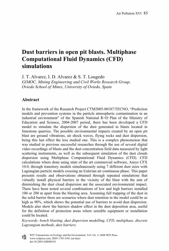
Following figure shows the model geometry including the virtual barriers domain and the dust injection points over the blasted bench.
Figure 1: Model geometry and dust injection points.
All the referred data was used to develop a multiphase CFD simulation, based in the numerical resolution of the differential equations that define the motion of a fluid. The equations that govern the fluid flow are the Navier Stokes, eqn (1), which relates the velocity and pressure fields as well as density; the continuity equation, eqn (2), that express the mass conservation; and finally the energy equation, eqn (3), which relates also the temperature fields. These expressions create a system of differential equations that can only be solved, in the vast majority of cases, by numerical methods.
VgpDtVD 2∇++∇−= µρρ (1)
0=•∇+ VDtD ρρ
(2)
VpTKDt
uD•∇−∇= 2
~ρ (3)
In turbulent flow there have also to be solved additional equations that allow the calculation of the velocity and pressure fields in all the domains, the so called “turbulence models”. Taking into account just the RANS (Reynolds Averaged Navier Stokes) they vary from the more or less simple where just one equation is added to the calculations, as the Spalart-Allmaras model, to the two equations models, k-epsilon or even seven equations, Shear Stress Transport (SST) models. This paper will show calculations that use k-epsilon models after mesh and turbulence model dependence tests accomplished in simulations in similar configurations [6] and using related bibliography [7]. All the calculations are made using commercial code Ansys CFX 10.0 and its deep documentation is also revised [8] to select adequate parameters for the simulation. The domain to be calculated is divided in finite volumes where the former equations will be solved by linear methods. The blowing air will be defined as a
www.witpress.com, ISSN 1743-3541 (on-line)
© 2008 WIT PressWIT Transactions on Ecology and the Environment, Vol 116,
Air Pollution XVI 87
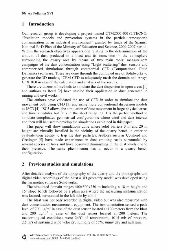
velocity profile following a classical logarithmic equation, as can be seen in documents from the U.S. Environmental Pollution Agency [9] as well as adequately oriented following the wind bearing measured in the field.
Figure 2: Dust emission area and air velocity.
Figure 2 shows the area where the dust will be injected simulating the dust emission in the blast. The bench acts as a obstacle in the wind path and the pressure and velocity fields will be modified in its vicinity, thus modifying the dust dispersion mechanism. The flow in this area must be calculated in detail, so a high density mesh will be used near the blast generated cone. As can be seen in the figure mesh is rougher as height is higher, as the wind will not vary so much in that area. The cut plane of figure 2 is coloured according to the air velocity. The logarithmic wind profile used in the inlet boundary condition, 2.5 m/s at 10 meters height, can be inferred at the left of the domain. In the bench the wind is accelerated by the bench presence to levels as high as 3.5 m/s. Another important parameter that has to be defined is the particle size distribution of the material that forms the dust cloud. As is shown by Almeida et al.[10] and Jones et al. [11] the particulated material thrown to the air by a blast has two main sources. First, rocks pulverized by the several phenomena that take
www.witpress.com, ISSN 1743-3541 (on-line)
© 2008 WIT PressWIT Transactions on Ecology and the Environment, Vol 116,
88 Air Pollution XVI
place in the blast (shock wave, high pressure gases or dynamic breaking mechanisms, etc.) and second the dusty products of the explosive chemical reaction. Both Almeida and Jones estimate the size distribution of the dust clouds in ranges from submicron sizes up to 50 microns. Particles over this size are also produced but have not been considered in the simulation as are quickly settled into ground by its own weight.
3 Installation of virtual barriers. Postprocessing
In open pit mines is quite common to find forests surrounding the installations. These trees constitute a barrier for the fugitive dust generated in the mine or quarry, thus avoiding its dispersion towards inhabited areas. Recent studies by Cowherd and Grelinger [5] about dust generation in unpaved roads determine that there are abnormally low levels of dust concentration dispersion in roads limited by trees. Cowherd studied the diminishing of the dust levels in presence of two vegetal species: low grass prairies and high oak trees forests.
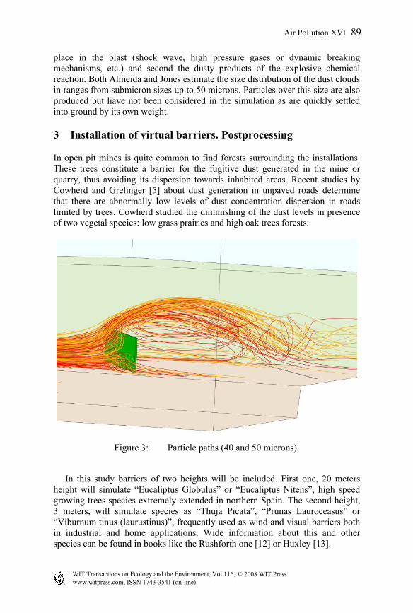
Figure 3: Particle paths (40 and 50 microns).
In this study barriers of two heights will be included. First one, 20 meters height will simulate “Eucaliptus Globulus” or “Eucaliptus Nitens”, high speed growing trees species extremely extended in northern Spain. The second height, 3 meters, will simulate species as “Thuja Picata”, “Prunas Lauroceasus” or “Viburnum tinus (laurustinus)”, frequently used as wind and visual barriers both in industrial and home applications. Wide information about this and other species can be found in books like the Rushforth one [12] or Huxley [13].
www.witpress.com, ISSN 1743-3541 (on-line)
© 2008 WIT PressWIT Transactions on Ecology and the Environment, Vol 116,
Air Pollution XVI 89
In figure 3 there can be seen how the dust particles trajectories are affected by the presence of the barrier. Table 1 shows the characteristics of the different simulation scenarios.
Table 1: Simulation scenarios.
Distance to
Dust source
Barrier
height SCENARIO
3 m A 100 m
20 m B
3 m C 200 m
20 m D
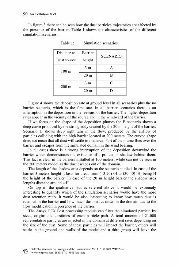
Figure 4 shows the deposition rate at ground level in all scenarios plus the no barrier scenario, which is the first one. In all barrier scenarios there is an interruption in the deposition in the leeward of the barrier. The higher deposition rates appear in the vicinity of the source and in the windward of the barrier. If we focus on the shape of the deposition plumes the B scenario shows a deep curve produced by the strong eddy created by the 20 m height of the barrier. Scenario D shows deep right turn in the flow, produced by the airflow of particles colliding with the high barrier located at 200 meters. The curved shape does not mean that all dust will settle in that area. Part of the plume flies over the barrier and escapes from the simulated domain in the wind bearing. In all cases there is a strong interruption of the deposition downwind the barrier which demonstrates the existence of a protection shadow behind them. This fact is clear in the barriers installed at 100 meters, while can not be seen in the 200 meters model as the dust escapes out of the domain. The length of the shadow area depends on the scenario studied. In case of the barrier 3 meters height it lasts for areas from (13-20) ·H to (30-40) ·H, being H the height of the barrier. In case of the 20 m height barrier the shadow area lengths distance around 4·H. On top of the qualitative studies referred above it would be extremely interesting to quantify which of the simulation scenarios would have the more dust retention ratio. It would be also interesting to know how much dust is retained in the barrier and how much dust settles down in the domain due to the flow modification in presence of the barrier. The Ansys CFX Post processing module can filter the simulated particle by sizes, origins and destinies of each particle path. A total amount of 21.000 representative particles are injected in the domain at different rates depending on the size of the dust. Some of these particles will impact the barrier, others will settle in the ground and walls of the model and a third group will leave the
www.witpress.com, ISSN 1743-3541 (on-line)
© 2008 WIT PressWIT Transactions on Ecology and the Environment, Vol 116,
90 Air Pollution XVI
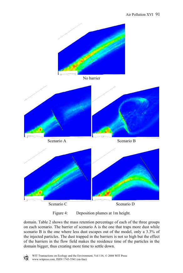
No barrier
Scenario A Scenario B
Scenario C Scenario D
Figure 4: Deposition plumes at 1m height.
domain. Table 2 shows the mass retention percentage of each of the three groups on each scenario. The barrier of scenario A is the one that traps more dust while scenario B is the one where less dust escapes out of the model, only a 3.3% of the injected particles. The dust trapped in the barriers is not so high but the effect of the barriers in the flow field makes the residence time of the particles in the domain bigger, thus creating more time to settle down.
www.witpress.com, ISSN 1743-3541 (on-line)
© 2008 WIT PressWIT Transactions on Ecology and the Environment, Vol 116,
Air Pollution XVI 91
Table 2: Mass retention percentage.
SCENARIOS Barrier Domain Escapes
A 6.69 57.78 35.53
B 1.25 95.45 3.3
C 4.936 57.15 37.91
D 1.28 74.56 24.16
4 Conclusions
All the tools used to make the simulations, from the field data to the several software used can effectively simulate the dispersion of the dust generated in a quarry blast. In this paper there have been included obstacles in the path of the particles in order to evaluate their trapping and avoid its dispersion in the surrounding environment. The barriers used are solid with heights of 3 m and 20 m located at 100 meters and at 200 meters from the blast. Simulations done quantify the dust emitted and the dust trapped in the barriers. The best trapping scenario is done when the barriers are located near the blast, with better trapping in case of high ones. Future simulations will take into account porosity and holes in the barrier installations.
Acknowledgements
We want to acknowledge the support from the Spanish Ministry of Science and Education that granted these researches through the project CTM2005-00187/TECNO, “Prediction models and prevention systems in the particle atmospheric contamination in an industrial environment”.
References
[1] Holmes N.S., Morawska L. A review of dispersion modelling and its application to the dispersion of particles: An overview of different dispersion models available. Atmospheric Environment 40 (2006) 5902–5928
[2] Reed,, W.R. Significant Dust Dispersion Models for Mining Operations. Information Circular 9478. National Institute for Occupational Safety and Health (NIOSH). September 2005
[3] J. Toraño et al. A CFD Lagrangian particle model to analyze the dust dispersion problem in quarries blasts. WIT Transactions on Engineering Sciences, Vol 56. ISSN 1743-3533. doi:10.2495/MPF070021. (2007)
www.witpress.com, ISSN 1743-3541 (on-line)
© 2008 WIT PressWIT Transactions on Ecology and the Environment, Vol 116,
92 Air Pollution XVI
[4] J. Toraño, R. Rodriguez, I. Diego and A. Pelegry, “Contamination by particulated material in blasts: analysis, application and adaptation of the existent calculation formulas and software”. Environmental Health Risk III, pp. 209–219, (2004)
[5] Cowherd C., Grelinger, M.A.. Development of an Emission Reduction Term for Near-Source Dust Depletion. 15th International Emission Inventory Conference. New Orleans, USA, May 15-18, 2006.
[6] Toraño J., Rodríguez R. and Diego I. Surface velocity contour analysis in the airborne dust generation due to open storage piles. European Conference on Computational Fluid Dynamics. ECCOMAS CFD 2006, Delft The Netherlands, 2006
[7] Silvester S.A., Lowndes I.S. and Kingman S.W. The ventilation of an underground crushing plant. Mining Technology (Trans. Inst. Min. Metall. A), Vol. 113, 201–214. (2004)
[8] ANSYS CFX-Solver, Release 10.0: Theory; Particle Transport Theory: Lagrangian Tracking Implementation; page 173.
[9] Environmental Pollution Agency. AP-42, 13.2.5.1, Miscellaneous Sources. Pp2. 1998.
[10] Almeida, S.M. Eston, S.M. and De Assunçao, J.V. “Characterization of Suspended Particulate Material in Mining Areas in Sao Paulo, Brazil.” I.T.. International Journal of surface Mining, Reclamation and Environment 2002, Vol. 16, no. 3, pp. 171–179
[11] Jones, T., Morgan, A. and Richards, R. “Primary blasting in a limestone quarry: physicochemical characterization of the dust clouds”. Mineralogical Magazine, April 2003, Vol 67(2), pp. 153–162
[12] Rushforth, K. Trees of Britain and Europe. Harper Collins (1999). [13] Huxley, A. New RHS Dictionary of Gardening. MacMillan (1992)
www.witpress.com, ISSN 1743-3541 (on-line)
© 2008 WIT PressWIT Transactions on Ecology and the Environment, Vol 116,
Air Pollution XVI 93