Embed Size (px)
Citation preview

Durable, Impermeable Brazes for Solid Oxide Fuel Cells
Dr. Jason D. Nicholas, Dr. Yue Qi, and Dr. Thomas R. Bieler
Department of Chemical Engineering and Materials ScienceMichigan State University
East Lansing, MI
Funded by the Department of Energy Solid Oxide Fuel Cell Core Technology Program through Agreement Number DE-FE0023315

Research Team• MSU:
• Jason D. Nicholas Lead PI, SOFC• Yue Qi PI, Computational Materials Science • Thomas R. Bieler PI, Metallurgy • Quan Zhou Graduate Student (Ni-based Brazes)• Yuxi Ma Graduate Student (Cu and Co-based Brazes)• Tridip Das Graduate Student (Simulations)
• Delphi: • Rick Kerr (and his team …) • Stephanie Surface • Bryan A. Gillispie
• NETL• Joseph Stoffa
2
Metal Picture Frame Suspended SOFC Schematic
Design and test new, SOFC-compatible, silver-free brazes with low oxygen and hydrogen permeability.
3
Project Objective:

Ag-based Brazes Can be Fabricated in Air and Don’t Oxidize at High Temperatures
4
Metals in Region I (like Silver) Won’t Oxidize in Air
Ag+Cu brazes undergo reactive air brazing

5C. Smithells, W. Gale, T. Totemeier. Smithells Metals Reference Book. 8th ed.
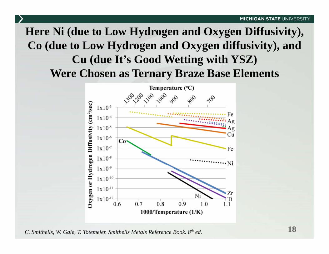
Oxygen Diffusivities (Solid Lines) and Hydrogen Diffusivity (Dotted Lines) for Several Common Metals

Standard Silver-Copper Brazes Have Durability Problems
6
• Type I Pores: Form During Manufacturing• Type II Pores: Form at Braze Interface due to CuO Reduction• Type III Pores: Form in Braze due to Water Pocket Formation
T. Bause, J. Malzbender et. al., Damage and Failure of Silver Based Ceramic/Metal Joints for SOFC Stacks,2013
Fuel Gas
(eg.H2)Air
(eg.O2)

Braze Alloy Design Criteria and Evaluation Methods
7
1. J. W. Fergus, Materials Science and Engineering A, 397, 271 (2005).2. A. Laik, P. Mishra, K. Bhanumurthy, G. B. Kale and B. P. Kashyap, Acta Materialia, 61, 126 (2013).3. A. Kar, S. Mandal, S. Rathod and A. K. Ray, in Brazing and Soldering: Proceedings of theThird International Brazing and Soldering
Conference April 24-26, 2006, San Antonio, TX, J. J. Stevens and K. Weil Editors, San Antonio, TX (2006).4. R. Kerr, Michigan State University/Delphi Cell to Retainer Braze Discussion, in, J. Nicholas Editor, Fenton, MI (2014).5. J. L. Margrave, The Characterization of High-Temperature Vapors, John Wiley & Sons, New York (1967).
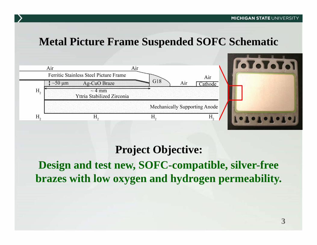
Braze Interface Design Criteria and Evaluation Methods
8
1. J. Y. Kim, J. S. Hardy and K. S. Weil, Journal of the American Ceramic Society, 88, 2521 (2005).2. J. L. Shi, T. S. Yen and H. Schubert, Journal of Materials Science, 32, 1341 (1997).3. J. C. Ruiz-Morales, J. Canales-Vazquez, D. Marrero-Lopez, J. Pena-Martinez, A. Tarancon, J. T. S. Irvine and P. Nunez,
Journal of Materials Chemistry, 18, 5072 (2008).
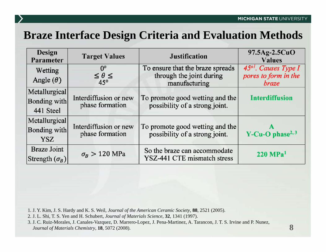
Brazed SOFC Design Criteria and Evaluation Methods
9
1. I. Barin and F. Sauert, Thermochemical data of pure substances, Weinheim, Federal Republic of Germany ; VCH, New York, NY, USA (1989).
2. R. A. Outlaw, S. N. Sankaran, G. B. Hoflund and M. R. Davidson, Journal of Materials Research, 3, 1378 (1988).3. J. Y. Kim, J. S. Hardy and S. Weil, International Journal of Hydrogen Energy, 32, 3655 (2007).4. R. Kerr, Michigan State University/Delphi Cell to Retainer Braze Discussion, in, J. Nicholas Editor, Fenton, MI (2014).

Sample Thermo-Calc ComputedNi-based Ternary phase diagram at 1000oC
Each corner of the hexagon is 100 mass % composition of the elements (mentioned at each corner).
Centre of the hexagon represents 100% Ni
Shows the liquid phases.
CoRu
Y Ti
Zr Cr
11
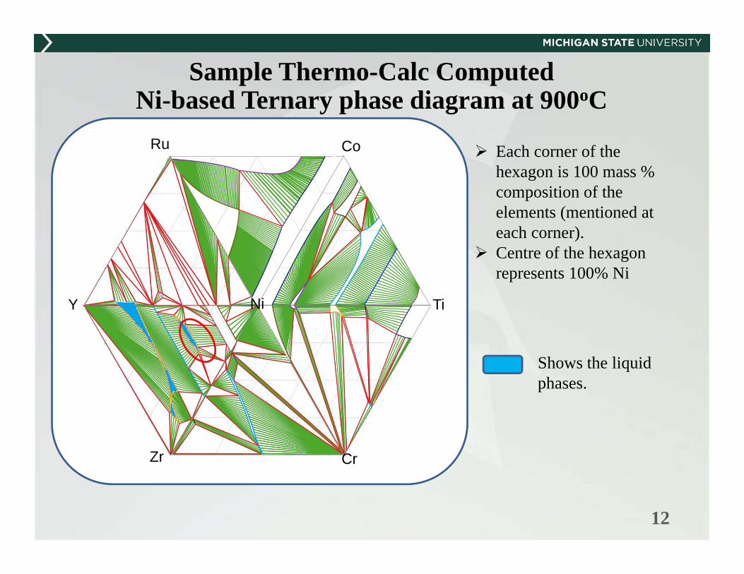
Sample Thermo-Calc ComputedNi-based Ternary phase diagram at 900oC
Each corner of the hexagon is 100 mass % composition of the elements (mentioned at each corner).
Centre of the hexagon represents 100% Ni
Shows the liquid phases.
CoRu
Y Ni Ti
Zr Cr
12

Sample Thermo-Calc ComputedNi-based Ternary phase diagram at 800oC
Each corner of the hexagon is 100 mass % composition of the elements (mentioned at each corner).
Centre of the hexagon represents 100% Ni
CoRu
Y Ni Ti
Zr Cr
13

Outline
• Background and Motivation• Benefits of Silver-Copper Brazes• Problems with Silver-Copper Brazes
• Methods• Results and Discussions
• Simulations• Oxidation Behavior of Top Candidates• Wetting Test on Different Substrates• A Preliminary Transient Multilayer Braze System
• Conclusions
13

14
Computation Led New Alloy Design• With the power of computation, hundreds of alloy systems can be effectively
screened, providing initial candidates for further optimization;
• Various techniques, characterization methods and strategies will be applied to solve different problems.

15
Prepare raw materials from 99.99% pure metals.(Cut, clean, weight) Select the right getter material to
secure the partial pressure of O2 during melting.
Purge with Argasvacuumthe chamber
melt the getters melt
the sample
Flip 5~10 times and re-melt
Diameter: ~0.5’’
Cut with high-speed diamond saw.
Braze Samples were Prepared with Arc Melting

Outline
• Background and Motivation• Benefits of Silver-Copper Brazes• Problems with Silver-Copper Brazes
• Methods• Results and Discussions
• Simulations• Oxidation Behavior• Wetting Tests• A Preliminary Transient Multilayer Braze System
• Conclusions
16

17
Here, all elements from the Periodic Table were considered but after dropping elements for the following reasons
Major Alloy Constituent Element Selection
25 elements remained: (B, C, Mg, Al, Si, V, Cr, Mn, Fe, Co, Ni, Cu, Zn, Ga, Nb, Mo, In, Sn, Ta, W, Ti, Y, Zr, Hf, Ag)
18C. Smithells, W. Gale, T. Totemeier. Smithells Metals Reference Book. 8th ed.
Here Ni (due to Low Hydrogen and Oxygen Diffusivity), Co (due to Low Hydrogen and Oxygen diffusivity), and
Cu (due It’s Good Wetting with YSZ) Were Chosen as Ternary Braze Base Elements
19
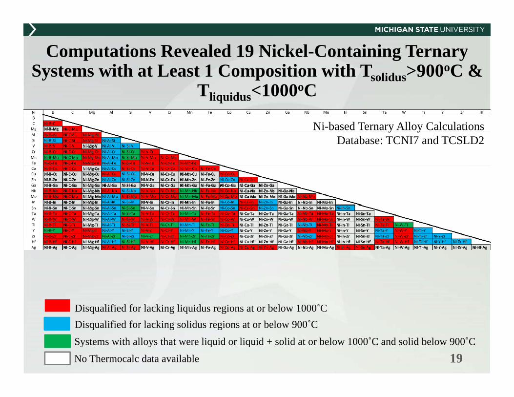
Computations Revealed 19 Nickel-Containing Ternary Systems with at Least 1 Composition with Tsolidus>900oC &
Tliquidus<1000oC
Disqualified for lacking liquidus regions at or below 1000˚CDisqualified for lacking solidus regions at or below 900˚C
Systems with alloys that were liquid or liquid + solid at or below 1000˚C and solid below 900˚C
No Thermocalc data available
Ni-based Ternary Alloy CalculationsDatabase: TCNI7 and TCSLD2

20
Computations Revealed 31 Cobalt-Containing Ternary Systems with at Least 1 Composition with Tsolidus>900oC &
Tliquidus<1000oCCo B C Mg Al Si V Cr Mn Fe Ni Cu Zn Ga Nb Mo In Sn Ta W Ti Y Zr Hf AgBC Co-B-C
Mg Co-B-Mg Co-C-MgAl Co-B-Al Co-C-Al Co-Mg-AlSi Co-B-Si Co-C-Si Co-Mg-Si Co-Al-SiV Co-B-V Co-C-V Co-Mg-V Co-Al-V Co-Si-VCr Co-B-Cr Co-C-Cr Co-Mg-Cr Co-Al-Cr Co-Si-Cr Co-V-CrMn Co-B-Mn Co-C-Mn Co-Mg-MnCo-Al-Mn Co-Si-Mn Co-V-Mn Co-Cr-MnFe Co-B-Fe Co-C-Fe Co-Mg-Fe Co-Al-Fe Co-Si-Fe Co-V-Fe Co-Cr-Fe Co-Mn-FeNi Co-B-Ni Co-C-Ni Co-Mg-Ni Co-Al-Ni Co-Si-Ni Co-V-Ni Co-Cr-Ni Co-Mn-Ni Co-Fe-NiCu Co-B-Cu Co-C-Cu Co-Mg-CuCo-Al-Cu Co-Si-Cu Co-V-Cu Co-Cr-Cu Co-Mn-Cu Co-Fe-Cu Co-Ni-CuZn Co-B-Zn Co-C-Zn Co-Mg-Zn Co-Al-Zn Co-Si-Zn Co-V-Zn Co-Cr-Zn Co-Mn-Zn Co-Fe-Zn Co-Ni-Zn Co-Cu-ZnGa Co-B-Ga Co-C-Ga Co-Mg-GaCo-Al-Ga Co-Si-Ga Co-V-Ga Co-Cr-Ga Co-Mn-Ga Co-Fe-Ga Co-Ni-Ga Co-Cu-Ga Co-Zn-GaNb Co-B-Nb Co-C-Nb Co-Mg-NbCo-Al-Nb Co-Si-Nb Co-V-Nb Co-Cr-Nb Co-Mn-Nb Co-Fe-Nb Co-Ni-Nb Co-Cu-Nb Co-Zn-Nb Co-Ga-NbMo Co-B-Mo Co-C-Mo Co-Mg-MoCo-Al-Mo Co-Si-Mo Co-V-Mo Co-Cr-Mo Co-Mn-Mo Co-Fe-Mo Co-Ni-Mo Co-Cu-MoCo-Zn-Mo Co-Ga-Mo Co-Nb-MoIn Co-B-In Co-C-In Co-Mg-In Co-Al-In Co-Si-In Co-V-In Co-Cr-In Co-Mn-In Co-Fe-In Co-Ni-In Co-Cu-In Co-Zn-In Co-Ga-In Co-Nb-In Co-Mo-InSn Co-B-Sn Co-C-Sn Co-Mg-Sn Co-Al-Sn Co-Si-Sn Co-V-Sn Co-Cr-Sn Co-Mn-Sn Co-Fe-Sn Co-Ni-Sn Co-Cu-Sn Co-Zn-Sn Co-Ga-Sn Co-Nb-Sn Co-Mo-Sn Co-In-SnTa Co-B-Ta Co-C-Ta Co-Mg-Ta Co-Al-Ta Co-Si-Ta Co-V-Ta Co-Cr-Ta Co-Mn-Ta Co-Fe-Ta Co-Ni-Ta Co-Cu-Ta Co-Zn-Ta Co-Ga-Ta Co-Nb-Ta Co-Mo-Ta Co-In-Ta Co-Sn-TaW Co-B-W Co-C-W Co-Mg-W Co-Al-W Co-Si-W Co-V-W Co-Cr-W Co-Mn-W Co-Fe-W Co-Ni-W Co-Cu-W Co-Zn-W Co-Ga-W Co-Nb-W Co-Mo-W Co-In-W Co-Sn-W Co-Ta-WTi Co-B-Ti Co-C-Ti Co-Mg-Ti Co-Al-Ti Co-Si-Ti Co-V-Ti Co-Cr-Ti Co-Mn-Ti Co-Fe-Ti Co-Ni-Ti Co-Cu-Ti Co-Zn-Ti Co-Ga-Ti Co-Nb-Ti Co-Mo-Ti Co-In-Ti Co-Sn-Ti Co-Ta-Ti Co-W-TiY Co-B-Y Co-C-Y Co-Mg-Y Co-Al-Y Co-Si-Y Co-V-Y Co-Cr-Y Co-Mn-Y Co-Fe-Y Co-Ni-Y Co-Cu-Y Co-Zn-Y Co-Ga-Y Co-Nb-Y Co-Mo-Y Co-In-Y Co-Sn-Y Co-Ta-Y Co-W-Y Co-Ti-YZr Co-B-Zr Co-C-Zr Co-Mg-Zr Co-Al-Zr Co-Si-Zr Co-V-Zr Co-Cr-Zr Co-Mn-Zr Co-Fe-Zr Co-Ni-Zr Co-Cu-Zr Co-Zn-Zr Co-Ga-Zr Co-Nb-Zr Co-Mo-Zr Co-In-Zr Co-Sn-Zr Co-Ta-Zr Co-W-Zr Co-Ti-Zr Co-Y-ZrHf Co-B-Hf Co-C-Hf Co-Mg-Hf Co-Al-Hf Co-Si-Hf Co-V-Hf Co-Cr-Hf Co-Mn-Hf Co-Fe-Hf Co-Ni-Hf Co-Cu-Hf Co-Zn-Hf Co-Ga-Hf Co-Nb-Hf Co-Mo-Hf Co-In-Hf Co-Sn-Hf Co-Ta-Hf Co-W-Hf Co-Ti-Hf Co-Y-Hf Co-Zr-HfAg Co-B-Ag Co-C-Ag Co-Mg-AgCo-Al-Ag Co-Si-Ag Co-V-Ag Co-Cr-Ag Co-Mn-Ag Co-Fe-Ag Co-Ni-Ag Co-Cu-Ag Co-Zn-Ag Co-Ga-Ag Co-Nb-Ag Co-Mo-Ag Co-In-Ag Co-Sn-Ag Co-Ta-Ag Co-W-Ag Co-Ti-Ag Co-Y-Ag Co-Zr-Ag Co-Hf-Ag
No liquid phase present in the phase diagram below 1000 °CThere exists some specific composition zone, which completely solidifies from liquid phase, between temperature window of 900 and 1000 °CThe composition of liquid zone at 1000 °C, remains liquid or solid+liquid below 900 °CNot available in database
Co-based Ternary Alloy CalculationsDatabase: TCIN7 and TCSLD2
Disqualified for lacking liquidus regions at or below 1000˚CDisqualified for lacking solidus regions at or below 900˚C
Systems with alloys that were liquid or liquid + solid at or below 1000˚C and solid below 900˚C
No Thermocalc data available

21
Computations Revealed 64 Copper-Containing Ternary Systems with at Least 1 Composition with Tsolidus>900oC &
Tliquidus<1000oCCu B C Mg Al Si V Cr Mn Fe Co Ni Zn Nb Mo In Sn Ta Ti Zr AgBC Cu-B-C
Mg Cu-B-Mg Cu-C-MgAl Cu-B-Al Cu-C-Al Cu-Mg-AlSi Cu-B-Si Cu-C-Si Cu-Mg-Si Cu-Al-SiV Cu-B-V Cu-C-V Cu-Mg-V Cu-Al-V Cu-Si-VCr Cu-B-Cr Cu-C-Cr Cu-Mg-Cr Cu-Al-Cr Cu-Si-Cr Cu-V-CrMn Cu-B-Mn Cu-C-Mn Cu-Mg-Mn Cu-Al-Mn Cu-Si-Mn Cu-V-Mn Cu-Cr-MnFe Cu-B-Fe Cu-C-Fe Cu-Mg-Fe Cu-Al-Fe Cu-Si-Fe Cu-V-Fe Cu-Cr-Fe Cu-Mn-FeCo Cu-B-Co Cu-C-Co Cu-Mg-Co Cu-Al-Co Cu-Si-Co Cu-V-Co Cu-Cr-Co Cu-Mn-Co Cu-Fe-CoNi Cu-B-Ni Cu-C-Ni Cu-Mg-Ni Cu-Al-Ni Cu-Si-Ni Cu-V-Ni Cu-Cr-Ni Cu-Mn-Ni Cu-Fe-Ni Cu-Co-NiZn Cu-B-Zn Cu-C-Zn Cu-Mg-Zn Cu-Al-Zn Cu-Si-Zn Cu-V-Zn Cu-Cr-Zn Cu-Mn-Zn Cu-Fe-Zn Cu-Co-Zn Cu-Ni-ZnNb Cu-B-Nb Cu-C-Nb Cu-Mg-Nb Cu-Al-Nb Cu-Si-Nb Cu-V-Nb Cu-Cr-Nb Cu-Mn-Nb Cu-Fe-Nb Cu-Co-Nb Cu-Ni-Nb Cu-Zn-NbMo Cu-B-Mo Cu-C-Mo Cu-Mg-Mo Cu-Al-Mo Cu-Si-Mo Cu-V-Mo Cu-Cr-Mo Cu-Mn-Mo Cu-Fe-Mo Cu-Co-MoCu-Ni-Mo Cu-Zn-Mo Cu-Nb-MoIn Cu-B-In Cu-C-In Cu-Mg-In Cu-Al-In Cu-Si-In Cu-V-In Cu-Cr-In Cu-Mn-In Cu-Fe-In Cu-Co-In Cu-Ni-In Cu-Zn-In Cu-Nb-In Cu-Mo-InSn Cu-B-Sn Cu-C-Sn Cu-Mg-Sn Cu-Al-Sn Cu-Si-Sn Cu-V-Sn Cu-Cr-Sn Cu-Mn-Sn Cu-Fe-Sn Cu-Co-Sn Cu-Ni-Sn Cu-Zn-Sn Cu-Nb-Sn Cu-Mo-Sn Cu-In-SnTa Cu-B-Ta Cu-C-Ta Cu-Mg-Ta Cu-Al-Ta Cu-Si-Ta Cu-V-Ta Cu-Cr-Ta Cu-Mn-Ta Cu-Fe-Ta Cu-Co-Ta Cu-Ni-Ta Cu-Zn-Ta Cu-Nb-Ta Cu-Mo-Ta Cu-In-Ta Cu-Sn-TaTi Cu-B-Ti Cu-C-Ti Cu-Mg-Ti Cu-Al-Ti Cu-Si-Ti Cu-V-Ti Cu-Cr-Ti Cu-Mn-Ti Cu-Fe-Ti Cu-Co-Ti Cu-Ni-Ti Cu-Zn-Ti Cu-Nb-Ti Cu-Mo-Ti Cu-In-Ti Cu-Sn-Ti Cu-Ta-TiZr Cu-B-Zr Cu-C-Zr Cu-Mg-Zr Cu-Al-Zr Cu-Si-Zr Cu-V-Zr Cu-Cr-Zr Cu-Mn-Zr Cu-Fe-Zr Cu-Co-Zr Cu-Ni-Zr Cu-Zn-Zr Cu-Nb-Zr Cu-Mo-Zr Cu-In-Zr Cu-Sn-Zr Cu-Ta-Zr Cu-Ti-ZrAg Cu-B-Ag Cu-C-Ag Cu-Mg-Ag Cu-Al-Ag Cu-Si-Ag Cu-V-Ag Cu-Cr-Ag Cu-Mn-Ag Cu-Fe-Ag Cu-Co-Ag Cu-Ni-Ag Cu-Zn-Ag Cu-Nb-Ag Cu-Mo-Ag Cu-In-Ag Cu-Sn-Ag Cu-Ta-Ag Cu-Ti-Ag Cu-Zr-Ag
No liquid phase present in the phase diagram below 1000 °CThere exists some specific composition zone, which completely solidifies from liquid phase, between temperature window of 900 and 1000 °CThe composition of liquid zone at 1000 °C, remains liquid or solid+liquid below 900 °CNot available in database
Cu-based Ternary Alloy CalculationsDatabase: TTTI3 and TCSLD2
Disqualified for lacking liquidus regions at or below 1000˚CDisqualified for lacking solidus regions at or below 900˚C
Systems with alloys that were liquid or liquid + solid at or below 1000˚C and solid below 900˚C
No Thermocalc data available

22
0.000
0.005
0.010
0.015
0.020
0.025
0.030
0.035
0 1000 2000 3000 4000 5000 6000 7000 8000
m (m
g*m
m-2)
Time (mins)
Ni20Ta5Si
Ni20Ta7Si1B
Ni20Ta7Si
BNi2 (commercial)Ni7Cr4.5Si3.1B3Fe
Ni20Ta10Si
Ni41.4In
Ni7Ta2Si
Ni10Si
Ni10Si1B
Ni32Ta7Si
Isothermally hold at 750°C, with 60 sccm of flowing air.
Ni-10Si(B) Showed Excellent Oxidation ResistanceSurface Area Normalize
d
23
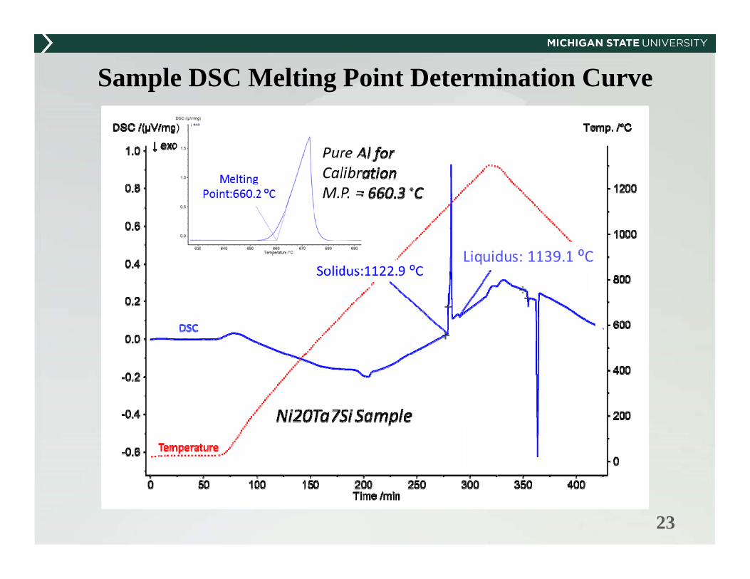
Sample DSC Melting Point Determination Curve
24
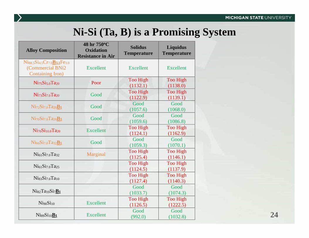
Ni-Si (Ta, B) is a Promising System Alloy Composition
48 hr 750oC Oxidation
Resistance in Air
Solidus Temperature
Liquidus Temperature
Ni88.5Si4.5Cr7.0B3.1Fe3.0 (Commercial BNi2
Containing Iron) Excellent Excellent Excellent
Ni75Si5.0Ta20 Poor Too High (1132.1)
Too High (1138.0)
Ni73Si7.0Ta20 Good Too High (1122.9)
Too High (1139.1)
Ni72Si7.0Ta20B1 Good Good (1057.6)
Good (1068.0)
Ni70Si7.0Ta20B3 Good Good (1059.6)
Good (1086.8)
Ni70Si10.0Ta20 Excellent Too High (1124.1)
Too High (1162.9)
Ni60Si7.0Ta32B1 Good Good (1059.3)
Good (1070.1)
Ni61Si7.0Ta32 Marginal Too High (1125.4)
Too High (1146.1)
Ni61Si7.0Ta25 Too High (1124.5)
Too High (1137.9)
Ni83Si7.0Ta10 Too High (1127.4)
Too High (1140.3)
Ni82Ta10Si7B1 Good
(1033.7) Good
(1074.3)
Ni90Si10 Excellent Too High (1126.5)
Too High (1222.5)
Ni89Si10B1 Excellent Good
(992.0) Good
(1032.8)
25
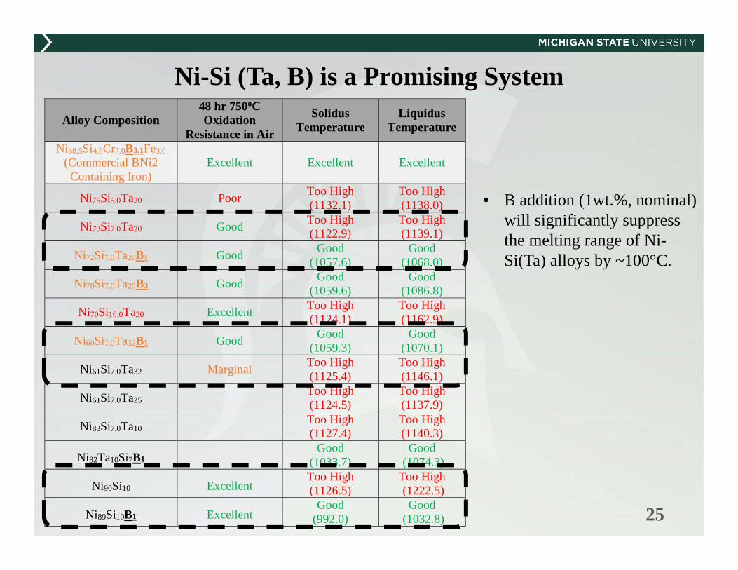
Ni-Si (Ta, B) is a Promising System Alloy Composition
48 hr 750oC Oxidation
Resistance in Air
Solidus Temperature
Liquidus Temperature
Ni88.5Si4.5Cr7.0B3.1Fe3.0 (Commercial BNi2
Containing Iron) Excellent Excellent Excellent
Ni75Si5.0Ta20 Poor Too High (1132.1)
Too High (1138.0)
Ni73Si7.0Ta20 Good Too High (1122.9)
Too High (1139.1)
Ni72Si7.0Ta20B1 Good Good (1057.6)
Good (1068.0)
Ni70Si7.0Ta20B3 Good Good (1059.6)
Good (1086.8)
Ni70Si10.0Ta20 Excellent Too High (1124.1)
Too High (1162.9)
Ni60Si7.0Ta32B1 Good Good (1059.3)
Good (1070.1)
Ni61Si7.0Ta32 Marginal Too High (1125.4)
Too High (1146.1)
Ni61Si7.0Ta25 Too High (1124.5)
Too High (1137.9)
Ni83Si7.0Ta10 Too High (1127.4)
Too High (1140.3)
Ni82Ta10Si7B1 Good
(1033.7) Good
(1074.3)
Ni90Si10 Excellent Too High (1126.5)
Too High (1222.5)
Ni89Si10B1 Excellent Good
(992.0) Good
(1032.8)
• B addition (1wt.%, nominal) will significantly suppress the melting range of Ni-Si(Ta) alloys by ~100°C.

26
Ni-Si (Ta, B) is a Promising System Alloy Composition
48 hr 750oC Oxidation
Resistance in Air
Solidus Temperature
Liquidus Temperature
Ni88.5Si4.5Cr7.0B3.1Fe3.0 (Commercial BNi2
Containing Iron) Excellent Excellent Excellent
Ni75Si5.0Ta20 Poor Too High (1132.1)
Too High (1138.0)
Ni73Si7.0Ta20 Good Too High (1122.9)
Too High (1139.1)
Ni72Si7.0Ta20B1 Good Good (1057.6)
Good (1068.0)
Ni70Si7.0Ta20B3 Good Good (1059.6)
Good (1086.8)
Ni70Si10.0Ta20 Excellent Too High (1124.1)
Too High (1162.9)
Ni60Si7.0Ta32B1 Good Good (1059.3)
Good (1070.1)
Ni61Si7.0Ta32 Marginal Too High (1125.4)
Too High (1146.1)
Ni61Si7.0Ta25 Too High (1124.5)
Too High (1137.9)
Ni83Si7.0Ta10 Too High (1127.4)
Too High (1140.3)
Ni82Ta10Si7B1 Good
(1033.7) Good
(1074.3)
Ni90Si10 Excellent Too High (1126.5)
Too High (1222.5)
Ni89Si10B1 Excellent Good
(992.0) Good
(1032.8)
• B addition (1wt.%, nominal) will significantly suppress the melting range of Ni-Si(Ta) alloys by ~100°C.
• Adding Ta into the Ni-Si system will reduce the liquidus temperature by ~60°C.

27
New Oxidation Mechanism can Provide a Different Angle in Alloy Design
BSE image of the cross-section of an oxidized Ni20Ta7Si1B sample (192hrs / flowing air / 750°C) and atomic percentages of
different elements from an EDS line scan.
• Although Ta addition seems to decrease the oxidation resistance, a different oxidation mechanism was observed.
• As shown in the EDS data, the “reaction layer” consists of a homogenized zone and a diffusion zone where Ta (and Si) diffuses toward the surface.
• Diffusion of Ta in the “reaction layer” might be the controlling process for the oxidation mechanism.

28
In situ Braze Wetting Measurement Setup
29
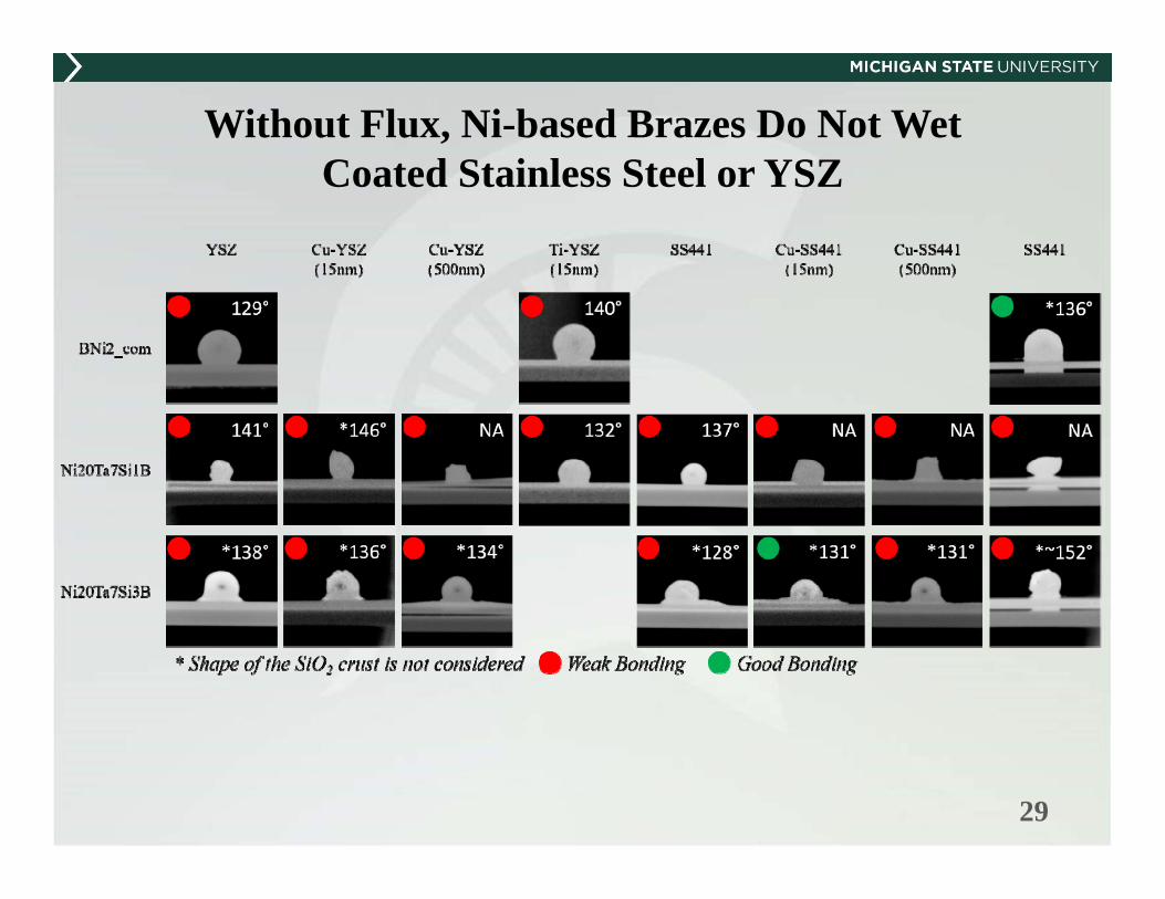
Without Flux, Ni-based Brazes Do Not Wet Coated Stainless Steel or YSZ

30
With Flux, Ni-based Brazes Wet Coated Stainless Steel or YSZ

Ni10Si1B
31
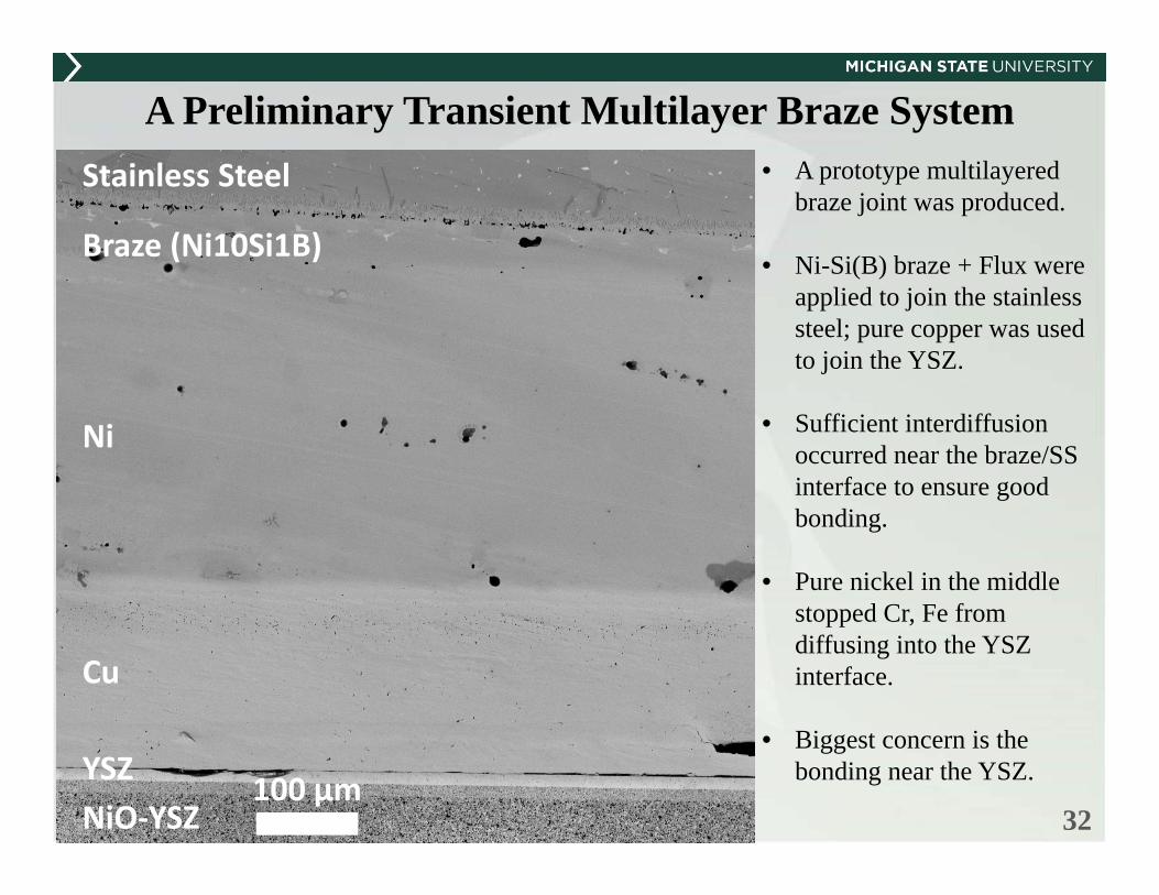
A Preliminary Transient Multilayer Braze System• A prototype multilayered
braze joint was produced.
• Ni-Si(B) braze + Flux were applied to join the stainless steel; pure copper was used to join the YSZ.
• Sufficient interdiffusion occurred near the braze/SS interface to ensure good bonding.
• Pure nickel in the middle stopped Cr, Fe from diffusing into the YSZ interface.
• Biggest concern is the bonding near the YSZ.
Ni10Si1B
32
A Preliminary Transient Multilayer Braze System
100 µm
Stainless Steel
Braze (Ni10Si1B)
Ni
Cu
YSZ NiO‐YSZ
• A prototype multilayered braze joint was produced.
• Ni-Si(B) braze + Flux were applied to join the stainless steel; pure copper was used to join the YSZ.
• Sufficient interdiffusion occurred near the braze/SS interface to ensure good bonding.
• Pure nickel in the middle stopped Cr, Fe from diffusing into the YSZ interface.
• Biggest concern is the bonding near the YSZ.

33
A Preliminary Transient Multilayer Braze System
100 µm
Stainless Steel
Braze (Ni10Si1B)
Ni
Cu
YSZ NiO‐YSZ
Fe
Ni
Cu
Cr
Si
ZrY
• A prototype multilayered braze joint was produced.
• Ni-Si(B) braze + Flux were applied to join the stainless steel; pure copper was used to join the YSZ.
• Sufficient interdiffusion occurred near the braze/SS interface to ensure good bonding.
• Pure nickel in the middle stopped Cr, Fe from diffusing into the YSZ interface.
• Biggest concern is the bonding near the YSZ.
100500 Atomic Percent

34
Conclusions
A Cr-free, Ni-10Si(1B) braze showed excellent oxidation resistancethat is better than the commercial BNi2 braze.
Ta reduces the liquidus temperature of the Ni-Si system by ~60°C and changes the oxidation mechanism, which might provide passivation.
A transient multilayer brazing system was explored, and a joint was successfully produced.
Besides its application in SOFCs, the Ni-Si (Ta, B) system provides a new family of brazes for general applications.
A systematic computation-experiment combined approach was established to search for, fabricate, and characterize new braze candidates for SOFC application.