Embed Size (px)
Citation preview
DUPONT™ ZYTEL® AND MINLON® NYLON RESINS MOLDING GUIDE
TABLE OF CONTENTS
1. PROCESSING GUIDELINE SUMMARY .................................1Drying Considerations ..........................................................1Mold Temperatures ...............................................................1Shrinkage Considerations .....................................................1Melt Temperatures................................................................1Operating Conditions ............................................................2
2. SAFE HANDLING INFORMATION .........................................2Safety Precautions................................................................2Regrinding Operation ...........................................................3Safety Information ................................................................3
3. GENERAL INFORMATION .....................................................3Foreword ..............................................................................3The DuPont Nylon Family .....................................................3Material Shipping ..................................................................4Handling Nylon Resins .........................................................4
Storage ............................................................................4Procedure for Handling Virgin Resin ................................4
4. DRYING GUIDELINES ............................................................5Effects of Moisture ...............................................................5Hopper Dryer Conditions ......................................................6Moisture Absorption .............................................................6
5. MOLDING EQUIPMENT—MOLDS ........................................7Mold Temperature Control ....................................................7Mechanical Structure ............................................................7Conventional Runner System and Gate Layout ....................8Hot Runner Systems .......................................................... 11Venting ...............................................................................12Draft Angles ........................................................................12Undercuts ..........................................................................12Sharp Corners .....................................................................13
6. MOLDING EQUIPMENT—INJECTION UNIT ......................13Screw .................................................................................13Check Ring or Back Flow Valve ...........................................13Corrosion/Abrasion .............................................................14Nozzles ...............................................................................14Accumulator for Thin Wall Applications ...............................14
7. MOLDING PARAMETERS—START-UP AND SHUTDOWN PROCEDURES .......................................................................15
Purging ...............................................................................15Start-up ...............................................................................15Shutdown ...........................................................................15
8. MOLDING PARAMETERS ....................................................16Melt and Cylinder Temperature ...........................................16Interruptions .......................................................................16Nozzle Temperature ............................................................17Cavity Temperature .............................................................17Injection Phase–Speed and Pressure .................................18Dynamic Pressure Drop (DPD) ...........................................19Pack or Hold Pressure Phase..............................................19
Hold Pressure Time (HPT) ..............................................20Cooling Time .......................................................................20Screw Retraction Phase .....................................................21
General Information .......................................................21Screw Rotation Speed and Back Pressure ....................21
Recommended Processing Parameters .............................21
9. MATERIAL BEHAVIOR .........................................................22Chemical Structure .............................................................22Crystallinity .........................................................................22Volume Changes ................................................................22Heating Requirements .......................................................23Melt Viscosity .....................................................................23
Dependence of Melt Viscosity upon Temperature .........23Dependence of Melt Viscosity upon Shear Rate ...........23Dependence of Melt Viscosity upon Moisture ..............24
Relative Viscosity ...............................................................24Melt Stability ......................................................................24
Hydrolysis ......................................................................24Thermal Degradation .....................................................24
Melt Temperature and Melting Point ..................................25Flow Length .......................................................................25Shrinkage ............................................................................26
Shrinkage of Zytel® and Minlon® Nylon ..........................26Post-Mold Shrinkage and Annealing ..............................27
Warpage .............................................................................27Water Absorption ...............................................................28Shrinkage (dimensional) Tolerance Field of Moldings .........29
10. AUXILIARY OPERATIONS ..................................................29Regrind ...............................................................................29Coloring ..............................................................................30
11. TROUBLESHOOTING GUIDE .............................................31
1
1. PROCESSING GUIDELINE SUMMARYZytel® PA thermoplastic polyamide resins and other DuPont thermoplastic resins may be processed on conventional injection molding machines using standard industry practices. Specific attention to processing details will enhance quality and productivity. This summary represents a key subset of the detailed molding information found in the remainder of this molding guide.
Drying ConsiderationsFor both virgin and rework, hopper dryers sized to afford the following conditions are strongly recommended:
• Moisture content must be below 0.2 wt%.
• Dry fresh bags for 2 to 4 hours at 80 °C (175 °F).
• Dryer dew point must remain below –18 °C (–0 °F).
• Air flow rate about 3.7 m3/h per kg/h of resin. being processed (1 cfm/lb/hr).
Note: Moisture content above 0.2% will result in loss of strength and toughness.
Mold TemperaturesDuPont™ Zytel® and Minlon® PA crystallize rapidly and can be successfully molded over a broad range of mold temperatures:
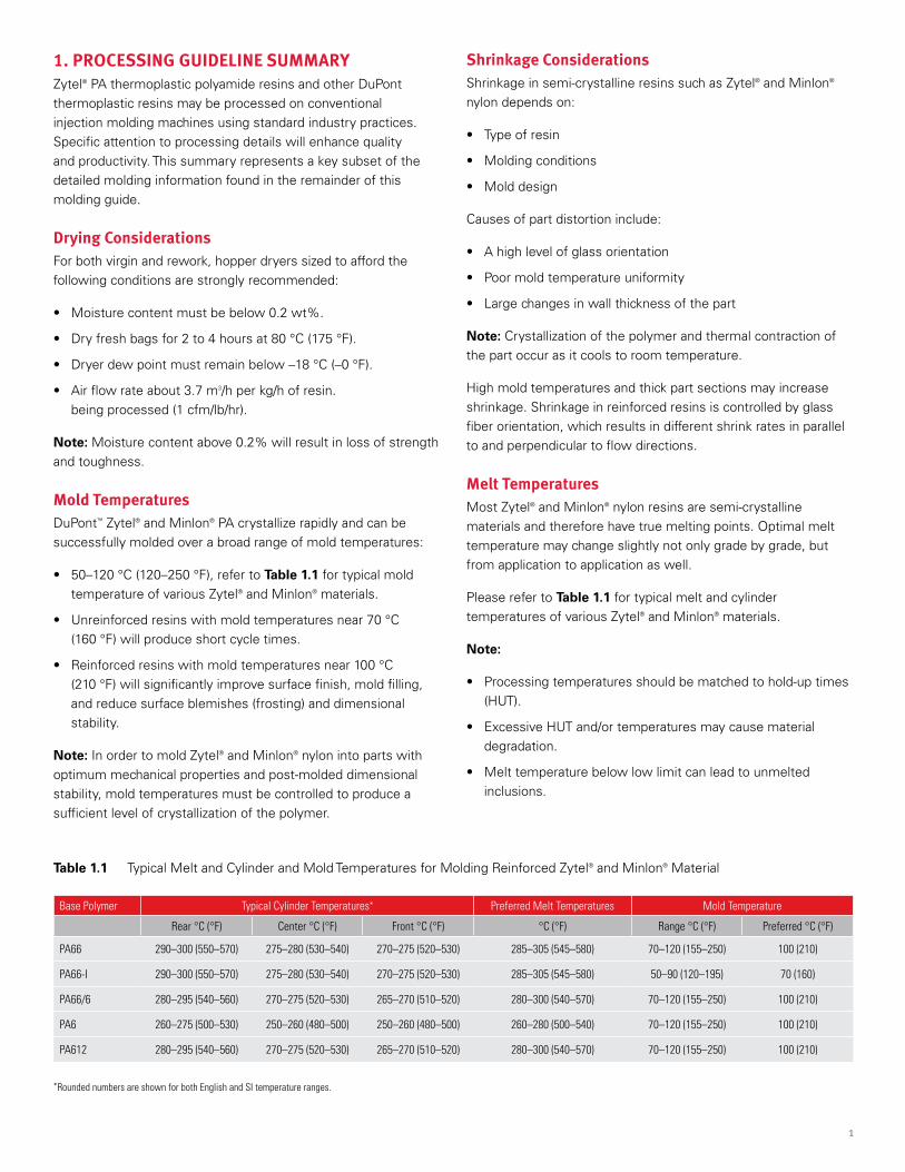
• 50–120 °C (120–250 °F), refer to Table 1.1 for typical mold temperature of various Zytel® and Minlon® materials.
• Unreinforced resins with mold temperatures near 70 °C (160 °F) will produce short cycle times.
• Reinforced resins with mold temperatures near 100 °C (210 °F) will significantly improve surface finish, mold filling, and reduce surface blemishes (frosting) and dimensional stability.
Note: In order to mold Zytel® and Minlon® nylon into parts with optimum mechanical properties and post-molded dimensional stability, mold temperatures must be controlled to produce a sufficient level of crystallization of the polymer.
Shrinkage ConsiderationsShrinkage in semi-crystalline resins such as Zytel® and Minlon® nylon depends on:
• Type of resin
• Molding conditions
• Mold design
Causes of part distortion include:
• A high level of glass orientation
• Poor mold temperature uniformity
• Large changes in wall thickness of the part
Note: Crystallization of the polymer and thermal contraction of the part occur as it cools to room temperature.
High mold temperatures and thick part sections may increase shrinkage. Shrinkage in reinforced resins is controlled by glass fiber orientation, which results in different shrink rates in parallel to and perpendicular to flow directions.
Melt TemperaturesMost Zytel® and Minlon® nylon resins are semi-crystalline materials and therefore have true melting points. Optimal melt temperature may change slightly not only grade by grade, but from application to application as well.
Please refer to Table 1.1 for typical melt and cylinder temperatures of various Zytel® and Minlon® materials.
Note:
• Processing temperatures should be matched to hold-up times (HUT).
• Excessive HUT and/or temperatures may cause material degradation.
• Melt temperature below low limit can lead to unmelted inclusions.
*Rounded numbers are shown for both English and SI temperature ranges.
Base Polymer Typical Cylinder Temperatures* Preferred Melt Temperatures Mold Temperature
Rear °C (°F) Center °C (°F) Front °C (°F) °C (°F) Range °C (°F) Preferred °C (°F)
PA66 290–300 (550–570) 275–280 (530–540) 270–275 (520–530) 285–305 (545–580) 70–120 (155–250) 100 (210)
PA66-I 290–300 (550–570) 275–280 (530–540) 270–275 (520–530) 285–305 (545–580) 50–90 (120–195) 70 (160)
PA66/6 280–295 (540–560) 270–275 (520–530) 265–270 (510–520) 280–300 (540–570) 70–120 (155–250) 100 (210)
PA6 260–275 (500–530) 250–260 (480–500) 250–260 (480–500) 260–280 (500–540) 70–120 (155–250) 100 (210)
PA612 280–295 (540–560) 270–275 (520–530) 265–270 (510–520) 280–300 (540–570) 70–120 (155–250) 100 (210)
Table 1.1 Typical Melt and Cylinder and Mold Temperatures for Molding Reinforced Zytel® and Minlon® Material
2
Note:
1. For unreinforced materials, preferred mold temperature shall be about 30 °C (50 °F) lower than corresponding reinforced grades.
2. For flame retardant grades, preferred melt temperature shall be about 15 °C (25 °F) lower than corresponding reinforced grades.
3. For detailed molding parameters settings, please refer to specific product data sheet.
Operating Conditions• Fast injection fill speeds (1–3 s), especially in thin sections.
Slow injection rates are desirable for thick section parts molding.
• Fast injection speed improves general surface appearance. High injection speed is necessary to glass-reinforced or otherwise nucleated nylon resins.
• Screw speeds adjusted to result in screw retraction times shorter than the cooling phase.
• Low [0.3 MPa (50 psi)] to no back pressure. Low back pressure may result in better melt quality and improved shot-to-shot uniformity.
• High screw speeds should be avoided with glass-reinforced resins to avoid loss of mechanical properties due to glass fiber breakage.
2. SAFE HANDLING INFORMATIONSafety PrecautionsProcessing thermoplastic resins is a generally safe operation when one complies with the following processing recommendations.
To minimize the chance of an accident, the instructions given in this text should be followed carefully. Potential hazards must be anticipated and either eliminated or guarded against by following established procedures including the use of proper protective equipment and clothing.
Be particularly alert during purging and whenever the resin is held in the machine or hot runner system at higher than usual temperatures or for longer than usual periods of time, as in a cycle interruption. Please read and ensure understanding of the sections on molding parameters thoroughly.
A. DuPont thermoplastic resins are molded at high temperatures and contact with molten resin can inflict severe burns. At temperatures above the melting point, moisture and other gases may generate pressure which, if suddenly released, can cause the molten polymer to be violently ejected from the machine nozzle.
B. In purging, be sure that the high volume (booster) pump is off and that a purge shield is in place. Reduce the injection pressure and “jog” the injection forward button a few times to minimize the possibility that trapped gas in the cylinder will cause “splattering” of the resin. In the event that molten polymer does contact the skin, cool the affected area immediately with cold water or an ice pack and get medical attention for thermal burn. Do not attempt to peel the polymer from the skin.
Best practice for limiting the evolution of odors and gases is to place the purged resin immediately into a metal container of cold water.
If during molding there is any suspicion that gases are being formed in the cylinder, move the purge shield in place, back the nozzle away from the mold, turn off all heat except to the nozzle and nozzle adapter, and leave the machine until it cools below the melting point of the resin. With purge shield still in place, reheat the cylinder to the minimum temperature, i.e, 15 °C (25 °F) greater than the resin melting point. If jogging the injection or screw rotation button does not produce melt flow, a plug exists. In that case, shut off cylinder heat as before and follow your established safety practices for removing the nozzle. Always assume that gas at high pressure could be trapped behind the nozzle and that it could be released unexpectedly. A face shield and protective long sleeve gloves should be used.
C. For resins requiring drying prior to use, pay special attention to prevent skin burns as these resins are dried at high temperature. Skin contact with hot hoppers, ovens or air hose lines could result in severe burns. Insulation of these
3
components will reduce this possibility. Similarly, for resins requiring hot mold temperatures, pay special attention to inadvertent contact with mold surfaces and cooling fluid transfer lines as these may also present a burn risk.
Small amounts of gases and particulate matter (i.e., low molecular weight modifiers) may be released during the molding, purging, drying, regrinding, and clean-up of thermoplastic resins. It is recommended that adequate local exhaust ventilation be provided during the processing of DuPont thermoplastic resins in order to meet regional requirements. It is necessary to consider the removal of dust and particles created during the distinct processes of drying, molding, purging and regrinding all while considering the maximum residence (hold-up) times and processing temperatures.
• Thermoplastic polymers can form gaseous decomposition products during long residence times (Hold-Up Times, HUT) at the maximum recommended melt temperatures.
• Adequate local exhaust ventilation must be provided during the regrind operation.
• Adequate local exhaust ventilation must be provided during the burnout of any equipment that contains thermoplastic resin, e.g., nozzles.
Refer to "Proper Use of Local Exhaust Ventilation During Processing of Plastics" for details.
D. Prior to cleaning of any barrel that contains thermoplastic resins, the machine should be thoroughly purged with polyethylene or polystyrene. If a thermoplastic resin is accidentally purged over the heater bands, it should be removed and not allowed to degrade.
E. Pellets or granules of thermoplastic resins present a slipping hazard if spilled on the floor because of their size and shape. They should be swept up immediately and disposed of appropriately.
Regrinding OperationWhen performing any regrinding operation, besides using equipment with state of the art safety performance, the installation should provide appropriate protection against noise and dust. Screens, filters and ventilation in good operating condition should be used. Operating personnel should wear adequate personal protective equipment including gloves and a face shield.
Safety InformationDuPont supplies Safety Data Sheet (SDS) of Zytel® and Minlon® resins to its customers with the initial order, upon the next order if there is a significant update to the SDS, and according to local regulatory update requirements. SDSs include such information as hazardous components, health hazards, emergency and first aid procedures, disposal procedures, and storage information.
3. GENERAL INFORMATIONForewordThis brochure consists of two parts. The first part presents a comprehensive overview of the injection molding process for nylons. The objective is to better understand what occurs during this molding process. The polymer characteristics and processing guidelines are designed to provide a comparison of the various attributes of different nylon families rather than in depth characteristics of specific grades.
The second part provides tables illustrating the most important setting parameters that are recommended during the injection molding process. The complete range of nylon resins from DuPont is listed.
The DuPont Nylon FamilyZytel® and Minlon® nylon resins are classified by chemical composition into the following groups:
• Nylon 66
• Nylon 6
• Nylon 66/6 copolymers
• Nylon 66 + 6 blends
• Nylon 612
• Transparent amorphous nylon
The key features of Zytel® nylons are:
• High mechanical strength
• Excellent balance of stiffness/toughness
• Good high temperature performance
• Good electrical and flammability properties
• Good abrasion and chemical resistance
Properties such as melting point, moisture absorption and modulus of elasticity are primarily determined by the type of nylon. The molecular weight of the nylon determines the melt viscosity and impact resistance.
In addition, nylons can be readily modified and reinforced, to create a wide range of products with tailored properties for specific processes and end-uses.
Major “families” of Zytel® nylons described in this brochure include:
4
• Unreinforced
• Tough/super tough
• Glass reinforced
• Mineral reinforced
• Mineral/glass reinforced
• Flame retardant
• High viscosity/extrusion
• Speciality
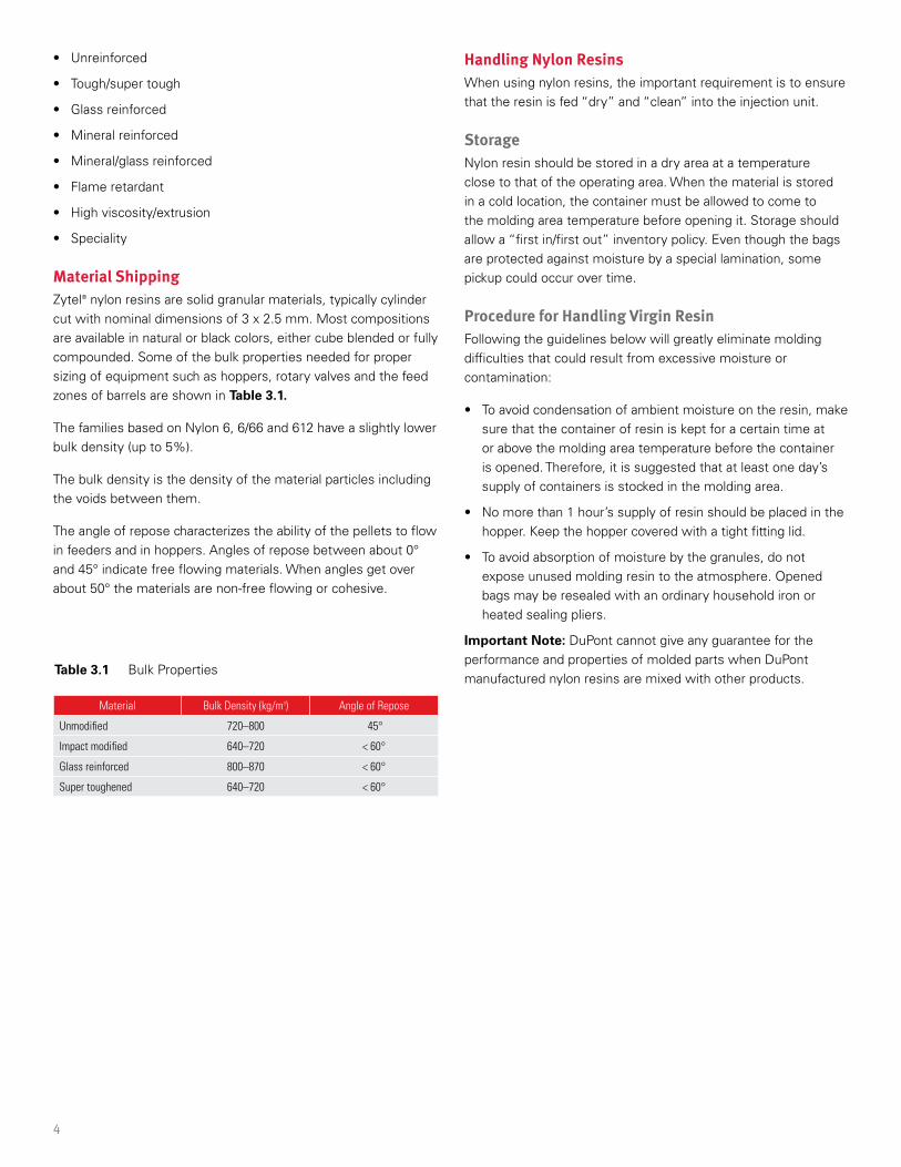
Material ShippingZytel® nylon resins are solid granular materials, typically cylinder cut with nominal dimensions of 3 x 2.5 mm. Most compositions are available in natural or black colors, either cube blended or fully compounded. Some of the bulk properties needed for proper sizing of equipment such as hoppers, rotary valves and the feed zones of barrels are shown in Table 3.1.
The families based on Nylon 6, 6/66 and 612 have a slightly lower bulk density (up to 5%).
The bulk density is the density of the material particles including the voids between them.
The angle of repose characterizes the ability of the pellets to flow in feeders and in hoppers. Angles of repose between about 0° and 45° indicate free flowing materials. When angles get over about 50° the materials are non-free flowing or cohesive.
Material Bulk Density (kg/m3) Angle of Repose
Unmodified 720–800 45°
Impact modified 640–720 < 60°
Glass reinforced 800–870 < 60°
Super toughened 640–720 < 60°
Handling Nylon ResinsWhen using nylon resins, the important requirement is to ensure that the resin is fed “dry” and “clean” into the injection unit.
StorageNylon resin should be stored in a dry area at a temperature close to that of the operating area. When the material is stored in a cold location, the container must be allowed to come to the molding area temperature before opening it. Storage should allow a “first in/first out” inventory policy. Even though the bags are protected against moisture by a special lamination, some pickup could occur over time.
Procedure for Handling Virgin ResinFollowing the guidelines below will greatly eliminate molding difficulties that could result from excessive moisture or contamination:
• To avoid condensation of ambient moisture on the resin, make sure that the container of resin is kept for a certain time at or above the molding area temperature before the container is opened. Therefore, it is suggested that at least one day’s supply of containers is stocked in the molding area.
• No more than 1 hour’s supply of resin should be placed in the hopper. Keep the hopper covered with a tight fitting lid.
• To avoid absorption of moisture by the granules, do not expose unused molding resin to the atmosphere. Opened bags may be resealed with an ordinary household iron or heated sealing pliers.
Important Note: DuPont cannot give any guarantee for the performance and properties of molded parts when DuPont manufactured nylon resins are mixed with other products.
Table 3.1 Bulk Properties
5
4. DRYING GUIDELINESMolded parts from DuPont thermoplastic resins provide an outstanding combination of tensile modulus, strength, toughness, dimensional stability and good surface appearance. However, these properties will not be achieved in finished molded parts unless the material has been properly processed. Proper drying of the resin is an important factor. The required drying can be accomplished in conventional drying equipment when careful attention is given to equipment selection, dryer operating conditions and maintenance procedures.
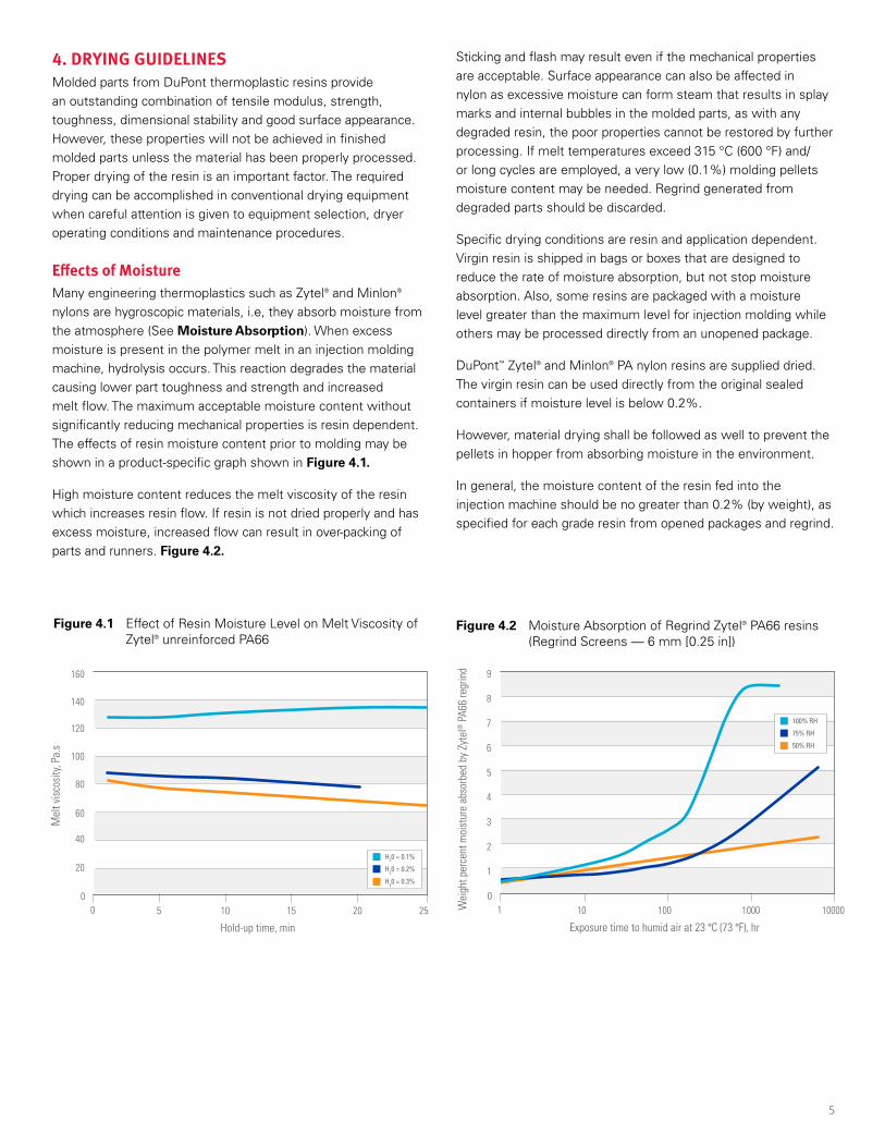
Effects of MoistureMany engineering thermoplastics such as Zytel® and Minlon® nylons are hygroscopic materials, i.e, they absorb moisture from the atmosphere (See Moisture Absorption). When excess moisture is present in the polymer melt in an injection molding machine, hydrolysis occurs. This reaction degrades the material causing lower part toughness and strength and increased melt flow. The maximum acceptable moisture content without significantly reducing mechanical properties is resin dependent. The effects of resin moisture content prior to molding may be shown in a product-specific graph shown in Figure 4.1.
High moisture content reduces the melt viscosity of the resin which increases resin flow. If resin is not dried properly and has excess moisture, increased flow can result in over-packing of parts and runners. Figure 4.2.
Figure 4.1 Effect of Resin Moisture Level on Melt Viscosity of Zytel® unreinforced PA66
Figure 4.2 Moisture Absorption of Regrind Zytel® PA66 resins (Regrind Screens — 6 mm [0.25 in])
Sticking and flash may result even if the mechanical properties are acceptable. Surface appearance can also be affected in nylon as excessive moisture can form steam that results in splay marks and internal bubbles in the molded parts, as with any degraded resin, the poor properties cannot be restored by further processing. If melt temperatures exceed 315 °C (600 °F) and/or long cycles are employed, a very low (0.1%) molding pellets moisture content may be needed. Regrind generated from degraded parts should be discarded.
Specific drying conditions are resin and application dependent. Virgin resin is shipped in bags or boxes that are designed to reduce the rate of moisture absorption, but not stop moisture absorption. Also, some resins are packaged with a moisture level greater than the maximum level for injection molding while others may be processed directly from an unopened package.
DuPont™ Zytel® and Minlon® PA nylon resins are supplied dried. The virgin resin can be used directly from the original sealed containers if moisture level is below 0.2%.
However, material drying shall be followed as well to prevent the pellets in hopper from absorbing moisture in the environment.
In general, the moisture content of the resin fed into the injection machine should be no greater than 0.2% (by weight), as specified for each grade resin from opened packages and regrind.
20
5 10 15 20 25
40
60
80
100
120
140
160
00
Hold-up time, min
Mel
t vis
cosi
ty, P
a.s
H20 = 0.1%
H20 = 0.2%
H20 = 0.3%
10 100 10000
7
6
5
4
3
2
1
8
9
01 1000
Exposure time to humid air at 23 °C (73 °F), hr
Wei
ght p
erce
nt m
oist
ure
abso
rbed
by
Zyte
l® P
A66
regr
ind
100% RH
75% RH
50% RH
6
Hopper Dryer ConditionsProperly operating desiccant-dehumidified-air or vacuum hopper dryers can dry thermoplastic resin adequately in a short period of time. Dehumidified or vacuum hopper dryer systems are necessary for successful drying of thermoplastic resins.
There are four critical parameters for dehumidified air systems: air flow, air temperature, air dew point and time.
The ideal air flow rate is determined by each kilogram (or pound) per hour of resin processed. For each kilogram (or pound) per hour that is processed, 3.0–3.7 m3 per kilogram per hour (or 0.8–1.0 cubic foot per minute, CFM, of air per pound of resin) is required. For example, if 27 kg/hr (60 lb/hr) of resin are to be molded, dry air capacity of 80–100 m3/hr (48–60 CFM) will be needed.
The air temperature is equally important and is related to the drying time. Air temperature should be measured at the point of entry to the hopper (not at the dryer). Prolonged drying at elevated temperatures can cause the loss of some additives and discoloration of pellets or require them to be dried longer than resin from unopened packages due to higher moisture content.
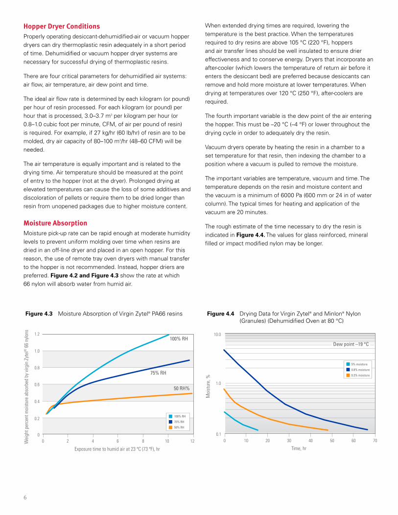
Moisture AbsorptionMoisture pick-up rate can be rapid enough at moderate humidity levels to prevent uniform molding over time when resins are dried in an off-line dryer and placed in an open hopper. For this reason, the use of remote tray oven dryers with manual transfer to the hopper is not recommended. Instead, hopper driers are preferred. Figure 4.2 and Figure 4.3 show the rate at which 66 nylon will absorb water from humid air.
Figure 4.3 Moisture Absorption of Virgin Zytel® PA66 resins Figure 4.4 Drying Data for Virgin Zytel® and Minlon® Nylon (Granules) (Dehumidified Oven at 80 °C)
When extended drying times are required, lowering the temperature is the best practice. When the temperatures required to dry resins are above 105 °C (220 °F), hoppers and air transfer lines should be well insulated to ensure drier effectiveness and to conserve energy. Dryers that incorporate an after-cooler (which lowers the temperature of return air before it enters the desiccant bed) are preferred because desiccants can remove and hold more moisture at lower temperatures. When drying at temperatures over 120 °C (250 °F), after-coolers are required.
The fourth important variable is the dew point of the air entering the hopper. This must be –20 °C (–4 °F) or lower throughout the drying cycle in order to adequately dry the resin.
Vacuum dryers operate by heating the resin in a chamber to a set temperature for that resin, then indexing the chamber to a position where a vacuum is pulled to remove the moisture.
The important variables are temperature, vacuum and time. The temperature depends on the resin and moisture content and the vacuum is a minimum of 6000 Pa (600 mm or 24 in of water column). The typical times for heating and application of the vacuum are 20 minutes.
The rough estimate of the time necessary to dry the resin is indicated in Figure 4.4. The values for glass reinforced, mineral filled or impact modified nylon may be longer.
0
0.2
0.4
0.6
0.8
1.0
1.2
0 2 4 6 8 10 12
Exposure time to humid air at 23 °C (73 °F), hr
Wei
ght p
erce
nt m
oist
ure
abso
rbed
by
virg
in Z
ytel
® 6
6 ny
lons
100% RH
75% RH
50 RH%
100% RH
75% RH
50% RH
10 20 30 40 50 60 70
1.0
10.0
0.10
Time, hr
Moi
stur
e, %
Dew point –19 °C
5% moisture
0.8% moisture
0.3% moisture
7
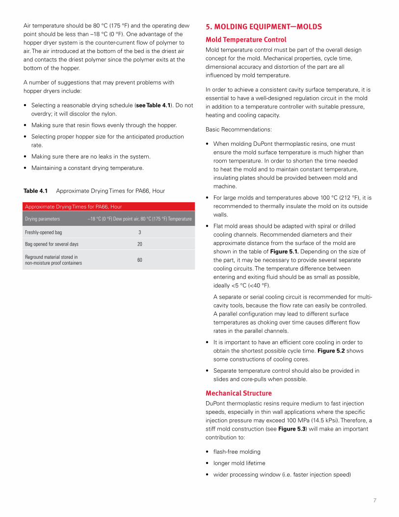
Table 4.1 Approximate Drying Times for PA66, Hour
Air temperature should be 80 °C (175 °F) and the operating dew point should be less than –18 °C (0 °F). One advantage of the hopper dryer system is the counter-current flow of polymer to air. The air introduced at the bottom of the bed is the driest air and contacts the driest polymer since the polymer exits at the bottom of the hopper.
A number of suggestions that may prevent problems with hopper dryers include:
• Selecting a reasonable drying schedule (see Table 4.1). Do not overdry; it will discolor the nylon.
• Making sure that resin flows evenly through the hopper.
• Selecting proper hopper size for the anticipated production rate.
• Making sure there are no leaks in the system.
• Maintaining a constant drying temperature.
Approximate Drying Times for PA66, Hour
Drying parameters –18 °C (0 °F) Dew point air, 80 °C (175 °F) Temperature
Freshly-opened bag 3
Bag opened for several days 20
Reground material stored innon-moisture proof containers 60
5. MOLDING EQUIPMENT—MOLDSMold Temperature ControlMold temperature control must be part of the overall design concept for the mold. Mechanical properties, cycle time, dimensional accuracy and distortion of the part are all influenced by mold temperature.
In order to achieve a consistent cavity surface temperature, it is essential to have a well-designed regulation circuit in the mold in addition to a temperature controller with suitable pressure, heating and cooling capacity.
Basic Recommendations:
• When molding DuPont thermoplastic resins, one must ensure the mold surface temperature is much higher than room temperature. In order to shorten the time needed to heat the mold and to maintain constant temperature, insulating plates should be provided between mold and machine.
• For large molds and temperatures above 100 °C (212 °F), it is recommended to thermally insulate the mold on its outside walls.
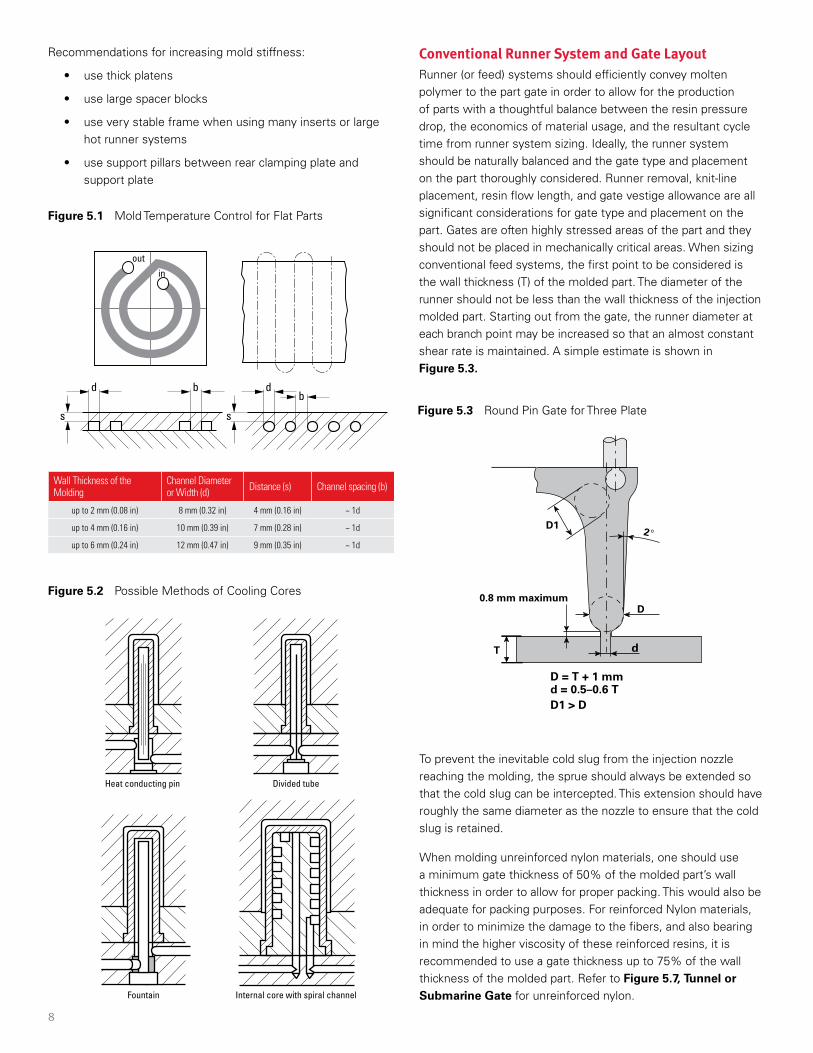
• Flat mold areas should be adapted with spiral or drilled cooling channels. Recommended diameters and their approximate distance from the surface of the mold are shown in the table of Figure 5.1. Depending on the size of the part, it may be necessary to provide several separate cooling circuits. The temperature difference between entering and exiting fluid should be as small as possible, ideally <5 °C (<40 °F).
A separate or serial cooling circuit is recommended for multi-cavity tools, because the flow rate can easily be controlled. A parallel configuration may lead to different surface temperatures as choking over time causes different flow rates in the parallel channels.
• It is important to have an efficient core cooling in order to obtain the shortest possible cycle time. Figure 5.2 shows some constructions of cooling cores.
• Separate temperature control should also be provided in slides and core-pulls when possible.
Mechanical StructureDuPont thermoplastic resins require medium to fast injection speeds, especially in thin wall applications where the specific injection pressure may exceed 100 MPa (14.5 kPsi). Therefore, a stiff mold construction (see Figure 5.3) will make an important contribution to:
• flash-free molding
• longer mold lifetime
• wider processing window (i.e. faster injection speed)
8
Figure 5.1 Mold Temperature Control for Flat Parts
d
outin
dbb
ss
Figure 5.2 Possible Methods of Cooling Cores
Figure 5.3 Round Pin Gate for Three Plate
Divided tube
Internal core with spiral channelFountain
Heat conducting pin
Conventional Runner System and Gate LayoutRunner (or feed) systems should efficiently convey molten polymer to the part gate in order to allow for the production of parts with a thoughtful balance between the resin pressure drop, the economics of material usage, and the resultant cycle time from runner system sizing. Ideally, the runner system should be naturally balanced and the gate type and placement on the part thoroughly considered. Runner removal, knit-line placement, resin flow length, and gate vestige allowance are all significant considerations for gate type and placement on the part. Gates are often highly stressed areas of the part and they should not be placed in mechanically critical areas. When sizing conventional feed systems, the first point to be considered is the wall thickness (T) of the molded part. The diameter of the runner should not be less than the wall thickness of the injection molded part. Starting out from the gate, the runner diameter at each branch point may be increased so that an almost constant shear rate is maintained. A simple estimate is shown in Figure 5.3.
2°
D
D1
0.8 mm maximum
dT
D = T + 1 mm d = 0.5–0.6 T D1 > D
To prevent the inevitable cold slug from the injection nozzle reaching the molding, the sprue should always be extended so that the cold slug can be intercepted. This extension should have roughly the same diameter as the nozzle to ensure that the cold slug is retained.
When molding unreinforced nylon materials, one should use a minimum gate thickness of 50% of the molded part’s wall thickness in order to allow for proper packing. This would also be adequate for packing purposes. For reinforced Nylon materials, in order to minimize the damage to the fibers, and also bearing in mind the higher viscosity of these reinforced resins, it is recommended to use a gate thickness up to 75% of the wall thickness of the molded part. Refer to Figure 5.7, Tunnel or Submarine Gate for unreinforced nylon.
Wall Thickness of the Molding
Channel Diameter or Width (d) Distance (s) Channel spacing (b)
up to 2 mm (0.08 in) 8 mm (0.32 in) 4 mm (0.16 in) ~ 1d
up to 4 mm (0.16 in) 10 mm (0.39 in) 7 mm (0.28 in) ~ 1d
up to 6 mm (0.24 in) 12 mm (0.47 in) 9 mm (0.35 in) ~ 1d
Recommendations for increasing mold stiffness:
• use thick platens
• use large spacer blocks
• use very stable frame when using many inserts or large hot runner systems
• use support pillars between rear clamping plate and support plate
9
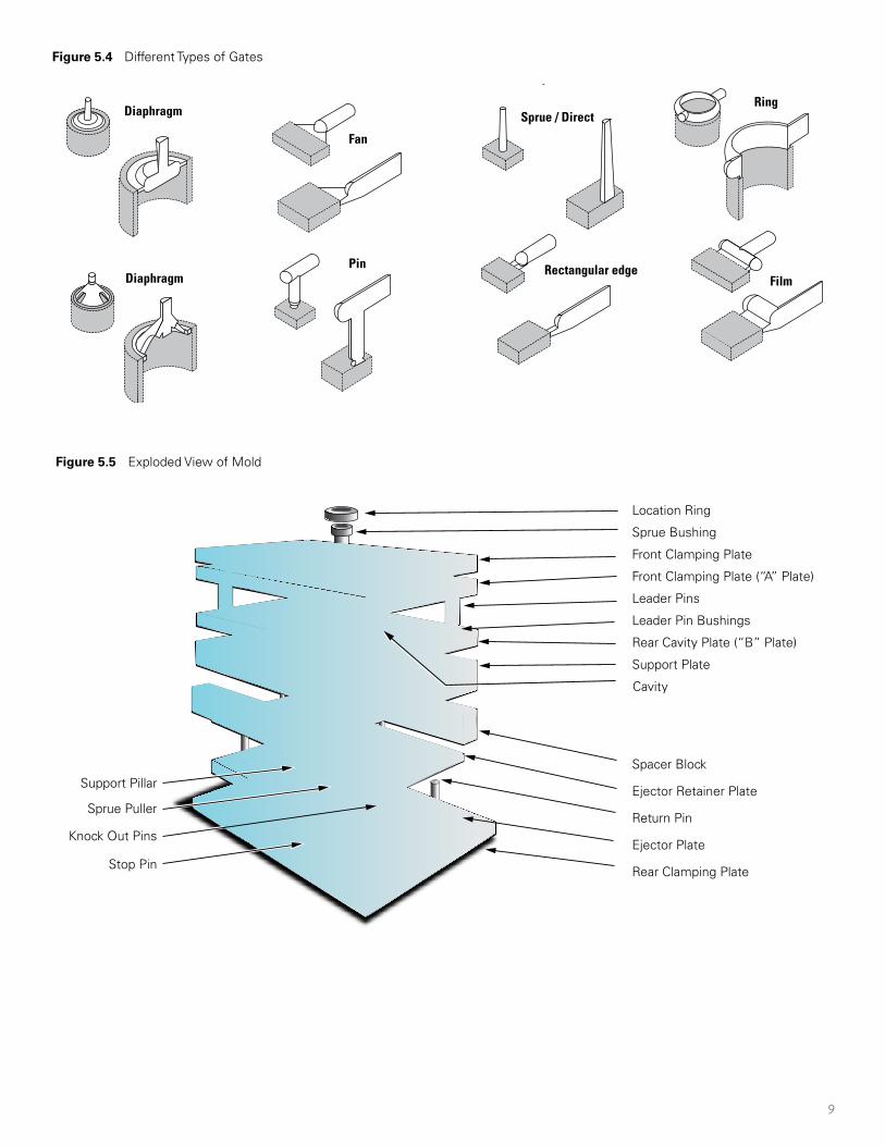
Figure 5.4 Different Types of Gates
Figure 5.5 Exploded View of Mold
Diaphragm
Diaphragm
Sprue / Direct
Rectangular edgeFilm
Fan
Pin
Ring
Diaphragm
Diaphragm
Sprue / Direct
Rectangular edgeFilm
Fan
Pin
Ring
Location Ring
Sprue Bushing
Front Clamping Plate
Front Clamping Plate (“A” Plate)
Leader Pins
Leader Pin Bushings
Rear Cavity Plate (“B” Plate)
Support Plate
Cavity
Ejector Retainer Plate
Return Pin
Spacer Block
Ejector PlateKnock Out Pins
Rear Clamping Plate
Support Pillar
Stop Pin
Sprue Puller
10
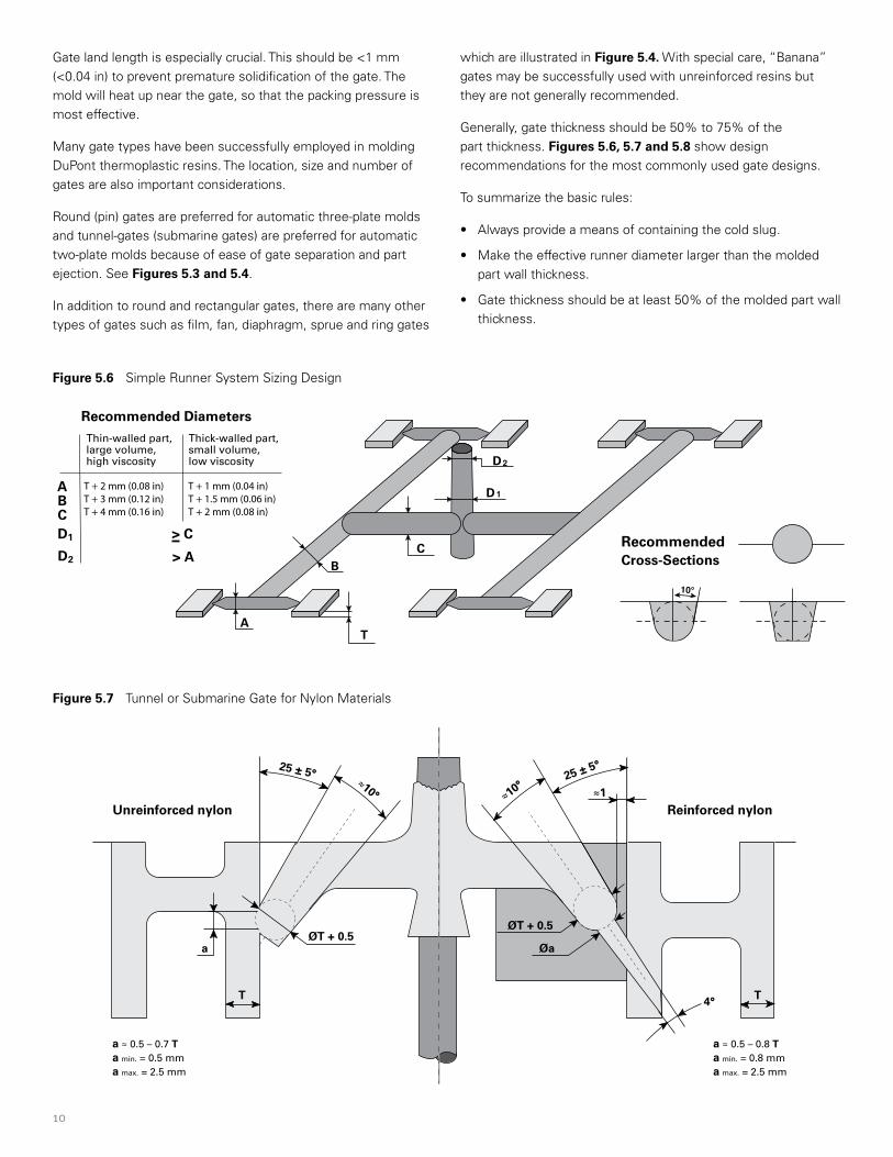
Figure 5.6 Simple Runner System Sizing Design
Figure 5.7 Tunnel or Submarine Gate for Nylon Materials
Recommended Diameters
Thin-walled part, Thick-walled part,large volume,high viscosity
small volume,low viscosity
A
B
A
C
T
BC
D1
D2
D1 > C
D2 > ARecommendedCross-Sections
10°
T + 2 mm (0.08 in) T + 1 mm (0.04 in)T + 3 mm (0.12 in) T + 1.5 mm (0.06 in)T + 4 mm (0.16 in) T + 2 mm (0.08 in)
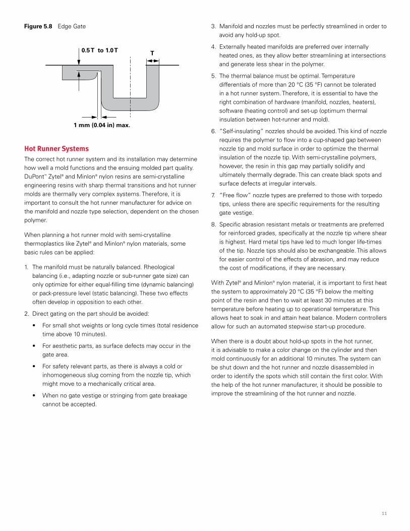
Gate land length is especially crucial. This should be <1 mm (<0.04 in) to prevent premature solidification of the gate. The mold will heat up near the gate, so that the packing pressure is most effective.
Many gate types have been successfully employed in molding DuPont thermoplastic resins. The location, size and number of gates are also important considerations.
Round (pin) gates are preferred for automatic three-plate molds and tunnel-gates (submarine gates) are preferred for automatic two-plate molds because of ease of gate separation and part ejection. See Figures 5.3 and 5.4.
In addition to round and rectangular gates, there are many other types of gates such as film, fan, diaphragm, sprue and ring gates
which are illustrated in Figure 5.4. With special care, “Banana” gates may be successfully used with unreinforced resins but they are not generally recommended.
Generally, gate thickness should be 50% to 75% of the part thickness. Figures 5.6, 5.7 and 5.8 show design recommendations for the most commonly used gate designs.
To summarize the basic rules:
• Always provide a means of containing the cold slug.
• Make the effective runner diameter larger than the molded part wall thickness.
• Gate thickness should be at least 50% of the molded part wall thickness.
Reinforced nylonUnreinforced nylon
a ≈ 0.5 – 0.7 Ta min. = 0.5 mma max. = 2.5 mm
a ≈ 0.5 – 0.8 Ta min. = 0.8 mma max. = 2.5 mm
ØaØT + 0.5
4°
25 ± 5°≈10°
25 ± 5°
≈10°≈1
ØT + 0.5
a
T T
11
Figure 5.8 Edge Gate
0.5 T to 1.0 T T
1 mm (0.04 in) max.
Hot Runner SystemsThe correct hot runner system and its installation may determine how well a mold functions and the ensuing molded part quality. DuPont™ Zytel® and Minlon® nylon resins are semi-crystalline engineering resins with sharp thermal transitions and hot runner molds are thermally very complex systems. Therefore, it is important to consult the hot runner manufacturer for advice on the manifold and nozzle type selection, dependent on the chosen polymer.
When planning a hot runner mold with semi-crystalline thermoplastics like Zytel® and Minlon® nylon materials, some basic rules can be applied:
1. The manifold must be naturally balanced. Rheological balancing (i.e., adapting nozzle or sub-runner gate size) can only optimize for either equal-filling time (dynamic balancing) or pack-pressure level (static balancing). These two effects often develop in opposition to each other.
2. Direct gating on the part should be avoided:
• For small shot weights or long cycle times (total residence time above 10 minutes).
• For aesthetic parts, as surface defects may occur in the gate area.
• For safety relevant parts, as there is always a cold or inhomogeneous slug coming from the nozzle tip, which might move to a mechanically critical area.
• When no gate vestige or stringing from gate breakage cannot be accepted.
3. Manifold and nozzles must be perfectly streamlined in order to avoid any hold-up spot.
4. Externally heated manifolds are preferred over internally heated ones, as they allow better streamlining at intersections and generate less shear in the polymer.
5. The thermal balance must be optimal. Temperature differentials of more than 20 °C (35 °F) cannot be tolerated in a hot runner system. Therefore, it is essential to have the right combination of hardware (manifold, nozzles, heaters), software (heating control) and set-up (optimum thermal insulation between hot-runner and mold).
6. “Self-insulating” nozzles should be avoided. This kind of nozzle requires the polymer to flow into a cup-shaped gap between nozzle tip and mold surface in order to optimize the thermal insulation of the nozzle tip. With semi-crystalline polymers, however, the resin in this gap may partially solidify and ultimately thermally degrade. This can create black spots and surface defects at irregular intervals.
7. “Free flow” nozzle types are preferred to those with torpedo tips, unless there are specific requirements for the resulting gate vestige.
8. Specific abrasion resistant metals or treatments are preferred for reinforced grades, specifically at the nozzle tip where shear is highest. Hard metal tips have led to much longer life-times of the tip. Nozzle tips should also be exchangeable. This allows for easier control of the effects of abrasion, and may reduce the cost of modifications, if they are necessary.
With Zytel® and Minlon® nylon material, it is important to first heat the system to approximately 20 °C (35 °F) below the melting point of the resin and then to wait at least 30 minutes at this temperature before heating up to operational temperature. This allows heat to soak in and attain heat balance. Modern controllers allow for such an automated stepwise start-up procedure.
When there is a doubt about hold-up spots in the hot runner, it is advisable to make a color change on the cylinder and then mold continuously for an additional 10 minutes. The system can be shut down and the hot runner and nozzle disassembled in order to identify the spots which still contain the first color. With the help of the hot runner manufacturer, it should be possible to improve the streamlining of the hot runner and nozzle.
12
VentingInadequate mold venting can cause the following problems:
• Poor weld line strength
• Discoloration (burning)
• Erosion or corrosion of the mold
• Dimensional variation on the molded part
• Surface aesthetic defects like bubbles or blisters
• Short shots
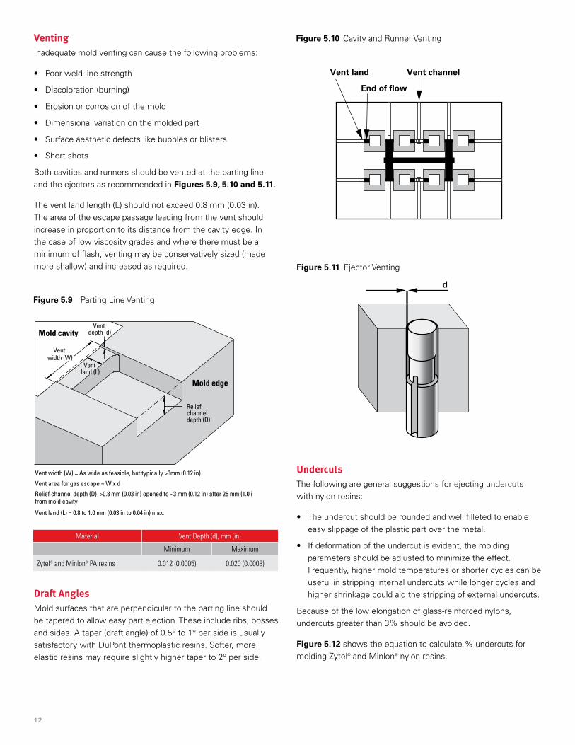
Both cavities and runners should be vented at the parting line and the ejectors as recommended in Figures 5.9, 5.10 and 5.11.
The vent land length (L) should not exceed 0.8 mm (0.03 in). The area of the escape passage leading from the vent should increase in proportion to its distance from the cavity edge. In the case of low viscosity grades and where there must be a minimum of flash, venting may be conservatively sized (made more shallow) and increased as required.
Figure 5.9 Parting Line Venting
Figure 5.10 Cavity and Runner Venting
Figure 5.11 Ejector Venting
Mold cavity
Mold edge
Relief channel depth (D)
Vent depth (d)
Vent width (W)
Vent land (L)
Vent width (W) = As wide as feasible, but typically >3mm (0.12 in)
Vent area for gas escape = W x d
Relief channel depth (D) >0.8 mm (0.03 in) opened to ~3 mm (0.12 in) after 25 mm (1.0 in) from mold cavity
Vent land (L) = 0.8 to 1.0 mm (0.03 in to 0.04 in) max.
Material Vent Depth (d), mm (in)
Minimum Maximum
Zytel® and Minlon® PA resins 0.012 (0.0005) 0.020 (0.0008)
Vent land
End of �ow
Vent channel
d
Undercuts The following are general suggestions for ejecting undercuts with nylon resins:
• The undercut should be rounded and well filleted to enable easy slippage of the plastic part over the metal.
• If deformation of the undercut is evident, the molding parameters should be adjusted to minimize the effect. Frequently, higher mold temperatures or shorter cycles can be useful in stripping internal undercuts while longer cycles and higher shrinkage could aid the stripping of external undercuts.
Because of the low elongation of glass-reinforced nylons, undercuts greater than 3% should be avoided.
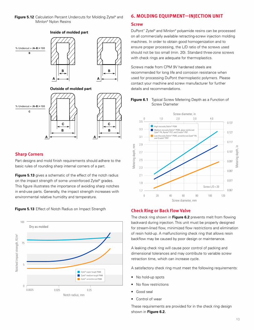
Figure 5.12 shows the equation to calculate % undercuts for molding Zytel® and Minlon® nylon resins.
Draft AnglesMold surfaces that are perpendicular to the parting line should be tapered to allow easy part ejection. These include ribs, bosses and sides. A taper (draft angle) of 0.5° to 1° per side is usually satisfactory with DuPont thermoplastic resins. Softer, more elastic resins may require slightly higher taper to 2° per side.
13
Figure 5.12 Calculation Percent Undercuts for Molding Zytel® and Minlon® Nylon Resins
Figure 5.13 Effect of Notch Radius on Impact Strength
Figure 6.1 Typical Screw Metering Depth as a Function of Screw Diameter
6. MOLDING EQUIPMENT—INJECTION UNITScrewDuPont™ Zytel® and Minlon® polyamide resins can be processed on all commercially available retracting-screw injection molding machines. In order to obtain good homogenization and to ensure proper processing, the L/D ratio of the screws used should not be too small (min. 20). Standard three-zone screws with check rings are adequate for thermoplastics.
Screws made from CPM 9V hardened steels are recommended for long life and corrosion resistance when used for processing DuPont thermoplastic polymers. Please contact your machine and screw manufacturer for further details and recommendations.
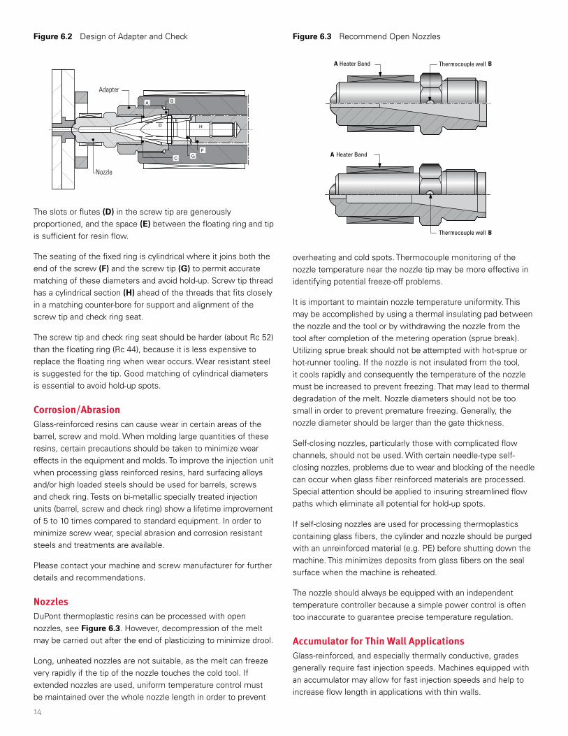
Check Ring or Back Flow ValveThe check ring shown in Figure 6.2 prevents melt from flowing backward during injection. This unit must be properly designed for stream-lined flow, minimized flow restrictions and elimination of resin hold-up. A malfunctioning check ring that allows resin backflow may be caused by poor design or maintenance.
A leaking check ring will cause poor control of packing and dimensional tolerances and may contribute to variable screw retraction time, which can increase cycle.
A satisfactory check ring must meet the following requirements:
• No hold-up spots
• No flow restrictions
• Good seal
• Control of wear
These requirements are provided for in the check ring design shown in Figure 6.2.
Sharp CornersPart designs and mold finish requirements should adhere to the basic rules of rounding sharp internal corners of a part.
Figure 5.13 gives a schematic of the effect of the notch radius on the impact strength of some unreinforced Zytel® grades. This figure illustrates the importance of avoiding sharp notches in end-use parts. Generally, the impact strength increases with environmental relative humidity and temperature.
High viscosity Delrin® POM
Medium viscosity Delrin® POM, glass reinforced Zytel® PA, Rynite® PET, and Crastin® PBT
Low Viscosity Delrin® POM, unreinforced Zytel® PA and Crastin® PBT
3.5
3.3
3.1
2.9
2.7
2.5
2.3
2.1
1.9
1.7
0.137
0.127
0.117
0.107
0.097
0.087
0.077
0.067
Met
erin
g de
pth,
mm
Met
erin
g de
pth,
in
Screw diameter, mm
Screw diameter, in
0 20 40 60 80 100 120
0
Screw L/D = 20
1.0 2.0 3.0 4.0
0.025
100
0
5
75
0.0025 0.25
Notch radius, mm
Not
ched
impa
ct s
treng
th, K
l/m2
Dry as molded
Zytel® super tough PA66
Zytel® medium tough PA66
Zytel® unreinforced PA66
Inside of molded part
Outside of molded part
% Undercut = (A–B) • 100
C
B
% Undercut = (A–B) • 100
A
B
B
C
A A
A
B
B
C
14
The slots or flutes (D) in the screw tip are generously proportioned, and the space (E) between the floating ring and tip is sufficient for resin flow.
The seating of the fixed ring is cylindrical where it joins both the end of the screw (F) and the screw tip (G) to permit accurate matching of these diameters and avoid hold-up. Screw tip thread has a cylindrical section (H) ahead of the threads that fits closely in a matching counter-bore for support and alignment of the screw tip and check ring seat.
The screw tip and check ring seat should be harder (about Rc 52) than the floating ring (Rc 44), because it is less expensive to replace the floating ring when wear occurs. Wear resistant steel is suggested for the tip. Good matching of cylindrical diameters is essential to avoid hold-up spots.
Corrosion/AbrasionGlass-reinforced resins can cause wear in certain areas of the barrel, screw and mold. When molding large quantities of these resins, certain precautions should be taken to minimize wear effects in the equipment and molds. To improve the injection unit when processing glass reinforced resins, hard surfacing alloys and/or high loaded steels should be used for barrels, screws and check ring. Tests on bi-metallic specially treated injection units (barrel, screw and check ring) show a lifetime improvement of 5 to 10 times compared to standard equipment. In order to minimize screw wear, special abrasion and corrosion resistant steels and treatments are available.
Please contact your machine and screw manufacturer for further details and recommendations.
NozzlesDuPont thermoplastic resins can be processed with open nozzles, see Figure 6.3. However, decompression of the melt may be carried out after the end of plasticizing to minimize drool.
Long, unheated nozzles are not suitable, as the melt can freeze very rapidly if the tip of the nozzle touches the cold tool. If extended nozzles are used, uniform temperature control must be maintained over the whole nozzle length in order to prevent
Figure 6.3 Recommend Open Nozzles Figure 6.2 Design of Adapter and Check
Nozzle
Adapter
A
D HE
B
GF
C
Thermocouple wellHeater BandA B
Heater Band
Thermocouple well
A
B
overheating and cold spots. Thermocouple monitoring of the nozzle temperature near the nozzle tip may be more effective in identifying potential freeze-off problems.
It is important to maintain nozzle temperature uniformity. This may be accomplished by using a thermal insulating pad between the nozzle and the tool or by withdrawing the nozzle from the tool after completion of the metering operation (sprue break). Utilizing sprue break should not be attempted with hot-sprue or hot-runner tooling. If the nozzle is not insulated from the tool, it cools rapidly and consequently the temperature of the nozzle must be increased to prevent freezing. That may lead to thermal degradation of the melt. Nozzle diameters should not be too small in order to prevent premature freezing. Generally, the nozzle diameter should be larger than the gate thickness.
Self-closing nozzles, particularly those with complicated flow channels, should not be used. With certain needle-type self-closing nozzles, problems due to wear and blocking of the needle can occur when glass fiber reinforced materials are processed. Special attention should be applied to insuring streamlined flow paths which eliminate all potential for hold-up spots.
If self-closing nozzles are used for processing thermoplastics containing glass fibers, the cylinder and nozzle should be purged with an unreinforced material (e.g. PE) before shutting down the machine. This minimizes deposits from glass fibers on the seal surface when the machine is reheated.
The nozzle should always be equipped with an independent temperature controller because a simple power control is often too inaccurate to guarantee precise temperature regulation.
Accumulator for Thin Wall ApplicationsGlass-reinforced, and especially thermally conductive, grades generally require fast injection speeds. Machines equipped with an accumulator may allow for fast injection speeds and help to increase flow length in applications with thin walls.
15
7. MOLDING PARAMETERS—START-UP AND SHUTDOWN PROCEDURES
PurgingPurging is essential before and after molding DuPont thermoplastic resins to prevent contamination. Contamination by another resin may occur by the degradation of that resin if it is processed at a much lower temperature. Unmelted contamination may occur by resins that process at a higher temperature.
If incompatible resins are mixed, a reaction may occur that degrades both resins. In severe cases, gases may form that cause the resins to be forced out of the nozzle or feed throat at high speeds.
The best purging materials are resins that are thermally stable under a broad range of temperatures and do not react with other polymers. Good purging resins are polystyrene, cast acrylic (the nozzle must be removed during purging) and high density polyethylene (or glass-reinforced polyethylene, followed by high density polyethylene). Commercial purging compounds may also be used, but it is best to follow them with a “standard” purging resin.
The following purge procedure is recommended for standard injection molding equipment:
A. Retract screw injection unit from the mold sprue bushing and keep the screw in the forward position.
B. Run the screw at high RPM and pump out as much of the current (first) material as possible. Add and extrude purge (second) material until it comes out clean. Cylinder temperatures may have to be adjusted, depending on the purge (second) material used.
C. It is good practice to “shoot” several air shots at a fast injection rate to scrub walls of cylinder before switching to another resin. Care should be used to avoid possible splatter of molten resin.
Start-upAlways consult the machine manufacturer’s recommendations for start-up. The following procedure can be used to supplement the machine manufacturer’s guidelines.
A. Start with a clean or well purged machine and a closed feed hopper inlet.
B. Set the cylinder temperature to 10 °C (20 °F) below the minimum recommended melt temperature and set the nozzle to the processing temperature. When starting up a cold molding machine, allow heat to “soak in” for at least 20 minutes. Raise cylinder temperature to the operating levels.
Please check the recommended processing parameters section for specific suggested conditions.
C. Confirm the nozzle is at the correct temperature.
D. Jog the screw. If the screw will not rotate, allow a longer soak time for cylinder temperature. If the screw does not rotate after a longer soak time, a higher melting resin may not have been completely purged from the barrel. Determine the previous resin used and see Purging section for guidance.
E. When the screw begins to rotate, open the hopper’s feed inlet briefly, allowing some resin to cover the screw and then close it. Rotate the screw while checking the torque on the screw drive. If the torque is excessive, increase rear zone temperature settings. The nozzle must be open at this time.
F. Open the hopper’s feed inlet and keep the screw in forward position. Start screw rotation and increase the front zone temperature if unmelted particles are seen.
G. The melt temperature should now be checked with a needle probe pyrometer. Make any adjustments in the cylinder temperatures necessary to obtain the recommended melt temperature. (This procedure should be repeated when a significant cycle change occurs.)
H. Bring injection cylinder forward. Start with a transfer position that will create a short shot and no pack pressure (except where short shots will interfere with safe part ejection). Establish the proper transfer position for the injection rate and then adjust the molding variables for the best part appearance and maximum part weight.
ShutdownThe machine should be purged thoroughly (see Purging) which cuts the time required for subsequent start-up and reduces risk of contamination. The following shutdown procedure is suggested:
A. Shut the hopper’s feed inlet while continuing to mold on cycle.
B. Empty the barrel and add a sufficient quantity of the appropriate purge resin such as polystyrene or polyethylene and extrude until the purge is clean. Run the screw until the screw pumps itself dry.
C. Leave screw in forward position.
D. Shut down power supply.
16
InterruptionsMolding cycle interruptions may cause the resin in the barrel of the molding machine or the hot manifold to degrade. The maximum time allowed before degradation occurs depends on the resin being molded and whether the processing temperature is at the upper or lower limit for that resin. Consult the processing guides for the resin being molded for specific recommendations.
In case of a short molding interruption, the following procedure is recommended in order to avoid degradation of the polymer.
1. Retract the injection unit.
2. Reduce the cylinder temperature settings and adjust the melt temperature to 30 °C (60 °F) below the recommended melt temperature.
3. During the interruption, take frequent air shots from the barrel to purge the degrading resin.
If the interruption is likely to be extended, purging with HDPE or polystyrene is recommended.
8. MOLDING PARAMETERSMelt and Cylinder TemperatureThe melt temperature is taken directly from the molten polymer (using a needle pyrometer) and should be checked periodically during a molding run to ensure that it does not exceed the recommended limits.
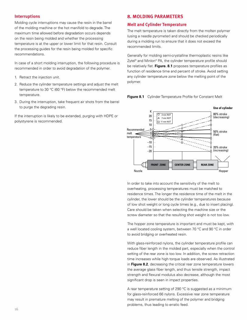
Generally for molding semi-crystalline thermoplastic resins like Zytel® and Minlon® PA, the cylinder temperature profile should be relatively flat. Figure. 8.1 proposes temperature profiles as function of residence time and percent of stroke. Avoid setting any cylinder temperature zone below the melting point of the polymer.
Figure 8.1 Cylinder Temperature Profile for Constant Melt
In order to take into account the sensitivity of the melt to overheating, processing temperatures must be matched to residence times. The longer the residence time of the melt in the cylinder, the lower should be the cylinder temperatures because of low shot weight or long cycle times (e.g., due to insert placing). Care should be taken when selecting the machine size or the screw diameter so that the resulting shot weight is not too low.
The hopper zone temperature is important and must be kept, with a well located cooling system, between 70 °C and 90 °C in order to avoid bridging or overheated resin.
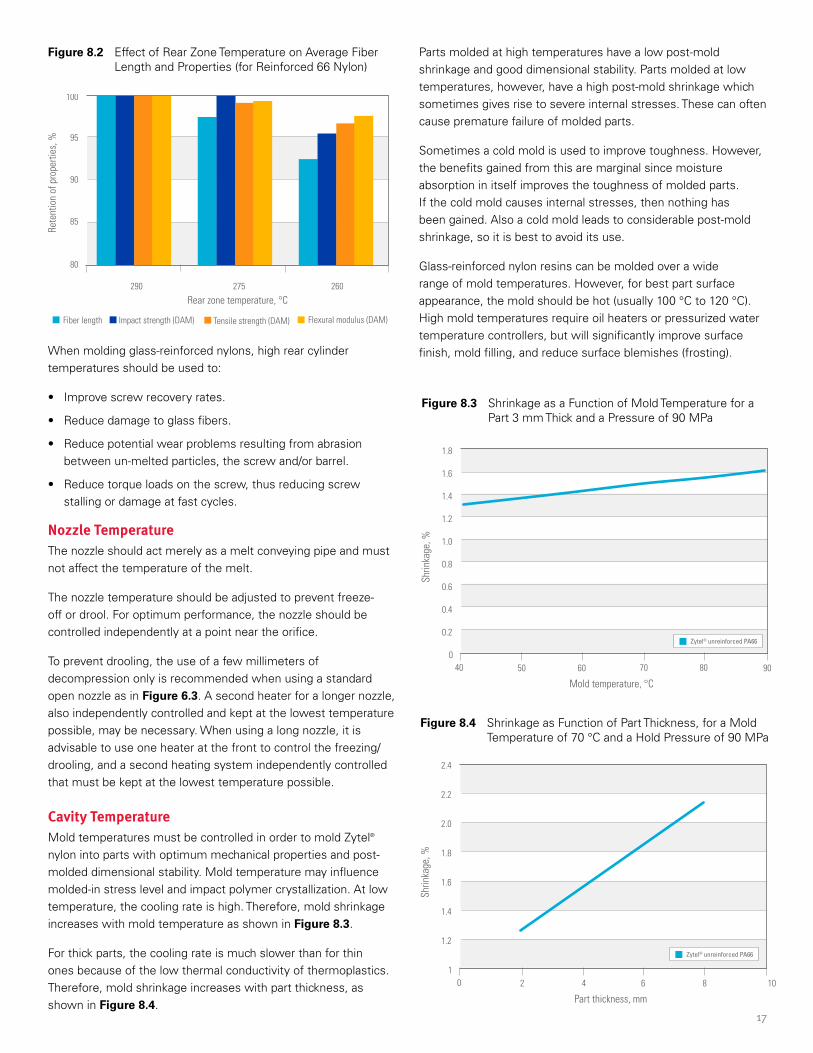
With glass-reinforced nylons, the cylinder temperature profile can reduce fiber length in the molded part, especially when the control setting of the rear zone is too low. In addition, the screw retraction time increases while high torque loads are observed. As illustrated in Figure 8.2, decreasing the critical rear zone temperature lowers the average glass fiber length, and thus tensile strength, impact strength and flexural modulus also decrease, although the most significant drop is seen in impact properties.
A rear temperature setting of 290 °C is suggested as a minimum for glass-reinforced 66 nylons. Excessive rear zone temperature may result in premature melting of the polymer and bridging problems, thus leading to erratic feed.
20K
Use of cylinder
1510
FRONT ZONE CENTER ZONE REAR ZONE
80% stroke(decreasing)
20% stroke(increasing)
HopperNozzle
50% stroke(�at)
Recommendedmelttemperature
–10–15–20
50
–5
7 min HUT
11 min HUT
3 min HUT
17
Figure 8.2 Effect of Rear Zone Temperature on Average Fiber Length and Properties (for Reinforced 66 Nylon)
When molding glass-reinforced nylons, high rear cylinder temperatures should be used to:
• Improve screw recovery rates.
• Reduce damage to glass fibers.
• Reduce potential wear problems resulting from abrasion between un-melted particles, the screw and/or barrel.
• Reduce torque loads on the screw, thus reducing screw stalling or damage at fast cycles.
Nozzle TemperatureThe nozzle should act merely as a melt conveying pipe and must not affect the temperature of the melt.
The nozzle temperature should be adjusted to prevent freeze-off or drool. For optimum performance, the nozzle should be controlled independently at a point near the orifice.
To prevent drooling, the use of a few millimeters of decompression only is recommended when using a standard open nozzle as in Figure 6.3. A second heater for a longer nozzle, also independently controlled and kept at the lowest temperature possible, may be necessary. When using a long nozzle, it is advisable to use one heater at the front to control the freezing/drooling, and a second heating system independently controlled that must be kept at the lowest temperature possible.
Cavity TemperatureMold temperatures must be controlled in order to mold Zytel® nylon into parts with optimum mechanical properties and post-molded dimensional stability. Mold temperature may influence molded-in stress level and impact polymer crystallization. At low temperature, the cooling rate is high. Therefore, mold shrinkage increases with mold temperature as shown in Figure 8.3.
For thick parts, the cooling rate is much slower than for thin ones because of the low thermal conductivity of thermoplastics. Therefore, mold shrinkage increases with part thickness, as shown in Figure 8.4.
Parts molded at high temperatures have a low post-mold shrinkage and good dimensional stability. Parts molded at low temperatures, however, have a high post-mold shrinkage which sometimes gives rise to severe internal stresses. These can often cause premature failure of molded parts.
Sometimes a cold mold is used to improve toughness. However, the benefits gained from this are marginal since moisture absorption in itself improves the toughness of molded parts. If the cold mold causes internal stresses, then nothing has been gained. Also a cold mold leads to considerable post-mold shrinkage, so it is best to avoid its use.
Glass-reinforced nylon resins can be molded over a wide range of mold temperatures. However, for best part surface appearance, the mold should be hot (usually 100 °C to 120 °C). High mold temperatures require oil heaters or pressurized water temperature controllers, but will significantly improve surface finish, mold filling, and reduce surface blemishes (frosting).
Figure 8.3 Shrinkage as a Function of Mold Temperature for a Part 3 mm Thick and a Pressure of 90 MPa
Figure 8.4 Shrinkage as Function of Part Thickness, for a Mold Temperature of 70 °C and a Hold Pressure of 90 MPa
260275290
80
85
90
95
100
Rear zone temperature, °C
Rete
ntio
n of
pro
perti
es, %
Fiber length Tensile strength (DAM) Flexural modulus (DAM)Impact strength (DAM)
50 60 90
1.4
1.2
1.0
0.8
0.6
0.4
0.2
1.6
1.8
040 70 80
Mold temperature, °C
Shrin
kage
, %
Zytel® unreinforced PA66
2 4 10
2.4
2.2
2.0
1.8
1.6
1.4
1.2
10 6 8
Part thickness, mm
Shrin
kage
, %
Zytel® unreinforced PA66
18
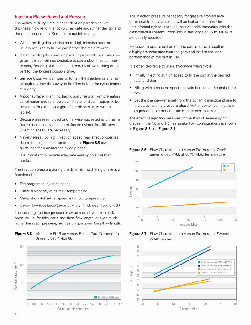
Injection Phase–Speed and PressureThe optimum filling time is dependent on part design, wall thickness, flow length, shot volume, gate and runner design, and the melt temperature. Some basic guidelines are:
• When molding thin section parts, high injection rates are usually required to fill the part before the resin freezes.
• When molding thick section parts or parts with relatively small gates, it is sometimes desirable to use a slow injection rate to delay freezing of the gate and thereby allow packing of the part for the longest possible time.
• Surface gloss will be more uniform if the injection rate is fast enough to allow the cavity to be filled before the nylon begins to solidify.
• A poor surface finish (frosting) usually results from premature solidification due to a too slow fill rate, and can frequently be mistaken for either poor glass fiber dispersion or wet resin (splay).
• Because glass-reinforced or otherwise nucleated nylon resins freeze more rapidly than unreinforced nylons, fast fill rates (injection speed) are necessary.
• Nevertheless, too high injection speed may affect properties due to too high shear rate at the gate. Figure 8.5 gives guidelines for unreinforced nylon grades.
It is important to provide adequate venting to avoid burn marks.
The injection pressure during the dynamic mold filling phase is a function of:
• The programed injection speed
• Material viscosity at its melt temperature
• Material crystallization speed and mold temperature
• Cavity flow resistance (geometry, wall thickness, flow length)
The resulting injection pressure may be much lower than pack pressure, i.e, for thick parts and short flow length; or even much higher than pack pressure, such as thin parts and long flow length.
Figure 8.5 Maximum Fill Rate Versus Round Gate Diameter for Unreinforced Nylon 66
Figure 8.7 Flow Characteristics Versus Pressure for Several Zytel® Grades
Figure 8.6 Flow Characteristics Versus Pressure for Zytel® unreinforced PA66 at 65 °C Mold Temperature
The injection pressure necessary for glass-reinforced and/or mineral filled nylon resins will be higher than those for unreinforced nylons, because melt viscosity increases with the glass/mineral content. Pressures in the range of 75 to 100 MPa are usually required.
Excessive pressure just before the part is full can result in a highly stressed area near the gate and lead to reduced performance of the part in use.
It is often desirable to use a two-stage filling cycle:
• Initially injecting at high speed to fill the part at the desired rate, and then
• Filling with a reduced speed to avoid burning at the end of the flow
• Set the change-over point from the dynamic injection phase to the static holding pressure phase (V/P or switch point) as late as possible, but not after the mold is completely full.
The effect of injection pressure on the flow of several nylon grades in the 1.0 and 2.5 mm snake flow configurations is shown in Figure 8.6 and Figure 8.7.
150
120
40
60
80
100
20
030 50 70 90 110 130
Pressure, MPa
Flow
, cm
2.5 mm
1.0 mm
3.2
1000
100
10
10.6 0.8 1.0 1.2 1.4 1.6 1.8 2.0 2.2 2.4 2.6 2.8 3.0
Round gate diameter, mm
Max
imum
cav
ity ra
te, %
Zytel® unreinforced PA66
140
120
40
50
60
90
80
70
110
100
20
20
30
20 40 60 80 100 120
Pressure, MPa
Flow
leng
th, c
m
Zytel® unreinforced PA66, mold 100 °C
Zytel® unreinforced PA66, mold 65 °C
Zytel® super tough PA66, mold 65 °C
Zytel® GR30% PA66, mold 100 °C
19
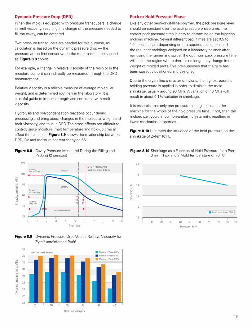
Figure 8.8 Cavity Pressure Measured During the Filling and Packing (2 sensors)
Figure 8.9 Dynamic Pressure Drop Versus Relative Viscosity for Zytel® unreinforced PA66
Dynamic Pressure Drop (DPD)When the mold is equipped with pressure transducers, a change in melt viscosity, resulting in a change of the pressure needed to fill the cavity, can be detected.
Two pressure transducers are needed for this purpose, as calculation is based on the dynamic pressure drop — the pressure at the first sensor when the melt reaches the second as Figure 8.8 shows.
For example, a change in relative viscosity of the resin or in the moisture content can indirectly be measured through the DPD measurement.
Relative viscosity is a reliable measure of average molecular weight, and is determined routinely in the laboratory. It is a useful guide to impact strength and correlates with melt viscosity.
Hydrolysis and polycondensation reactions occur during processing and bring about changes in the molecular weight and melt viscosity, and thus in DPD. The cross effects are difficult to control, since moisture, melt temperature and hold-up time all affect the reactions. Figure 8.9 shows the relationship between DPD, RV and moisture content for nylon 66.
Pack or Hold Pressure PhaseLike any other semi-crystalline polymer, the pack pressure level should be constant over the pack pressure phase time. The correct pack pressure time is easy to determine on the injection molding machine. Several different pack times are set 0.5 to 1.0 second apart, depending on the required resolution, and the resultant moldings weighed on a laboratory balance after removing the runner and sprue. The optimum pack pressure time will be in the region where there is no longer any change in the weight of molded parts. This pre-supposes that the gate has been correctly positioned and designed.
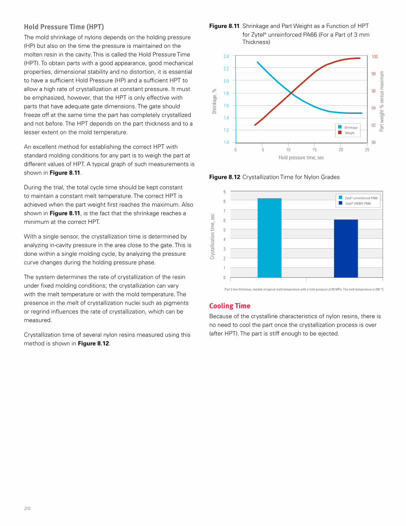
Due to the crystalline character of nylons, the highest possible holding pressure is applied in order to diminish the mold shrinkage, usually around 90 MPa. A variation of 10 MPa will result in about 0.1% variation in shrinkage.
It is essential that only one pressure setting is used on the machine for the whole of the hold pressure time. If not, then the molded part could show non-uniform crystallinity, resulting in lower mechanical properties.
Figure 8.10 illustrates the influence of the hold pressure on the shrinkage of Zytel® 101 L.
Figure 8.10 Shrinkage as a Function of Hold Pressure for a Part 3 mm Thick and a Mold Temperature of 70 °C
24
22
26
28
30
32
34
36Wall thickness 2.0 mm
2051 50 49 48 47 46
Dyna
mic
pre
ssur
e dr
op, M
Pa
Relative viscosity
Moisture of Resin 0.08%
Moisture of Resin 0.15%
Moisture of Resin 0.22%
100
1.0
1.2
1.4
1.6
1.8
2.0
0 10 20 30 40 706050 80 90
Pressure, MPa
Shrin
kage
, %
Zytel® unreinforced PA66
120
40
60
80
100
Zytel® GR30% PA66 wall thickness 2.0 mm
20
0 1 2 3 4 5 6 7 8 9 10
Time, sec
In-c
avity
pre
ssur
e, M
Pa
Sensor 1
CT 5
.27
s
CT 6
.0 s
In-cavity hold pressure
Hold pressure time
Dynamic pressure drop
Dynamic �lling time
Sensor 2
20
Hold Pressure Time (HPT)The mold shrinkage of nylons depends on the holding pressure (HP) but also on the time the pressure is maintained on the molten resin in the cavity. This is called the Hold Pressure Time (HPT). To obtain parts with a good appearance, good mechanical properties, dimensional stability and no distortion, it is essential to have a sufficient Hold Pressure (HP) and a sufficient HPT to allow a high rate of crystallization at constant pressure. It must be emphasized, however, that the HPT is only effective with parts that have adequate gate dimensions. The gate should freeze off at the same time the part has completely crystallized and not before. The HPT depends on the part thickness and to a lesser extent on the mold temperature.
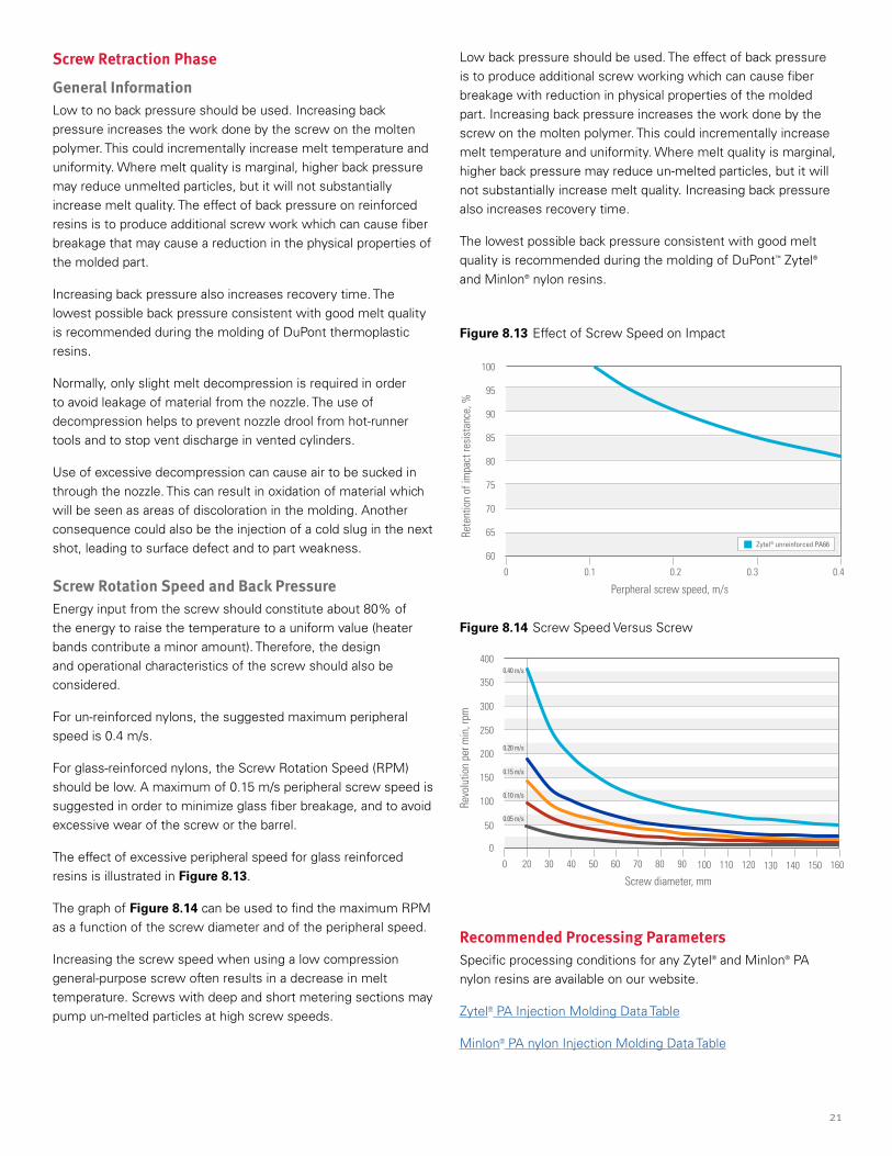
An excellent method for establishing the correct HPT with standard molding conditions for any part is to weigh the part at different values of HPT. A typical graph of such measurements is shown in Figure 8.11.
During the trial, the total cycle time should be kept constant to maintain a constant melt temperature. The correct HPT is achieved when the part weight first reaches the maximum. Also shown in Figure 8.11, is the fact that the shrinkage reaches a minimum at the correct HPT.
With a single sensor, the crystallization time is determined by analyzing in-cavity pressure in the area close to the gate. This is done within a single molding cycle, by analyzing the pressure curve changes during the holding pressure phase.
The system determines the rate of crystallization of the resin under fixed molding conditions; the crystallization can vary with the melt temperature or with the mold temperature. The presence in the melt of crystallization nuclei such as pigments or regrind influences the rate of crystallization, which can be measured.
Crystallization time of several nylon resins measured using this method is shown in Figure 8.12.
Figure 8.11 Shrinkage and Part Weight as a Function of HPT for Zytel® unreinforced PA66 (For a Part of 3 mm Thickness)
Figure 8.12 Crystallization Time for Nylon Grades
Cooling TimeBecause of the crystalline characteristics of nylon resins, there is no need to cool the part once the crystallization process is over (after HPT). The part is stiff enough to be ejected.
2
1
3
4
5
6
7
9
8
0
Crys
talli
zatio
n tim
e, s
ec
Zytel® unreinforced PA66
Zytel® GR30% PA66
Part 2 mm thickness, molded at typical mold temperature with a hold pressure of 85 MPa. The melt temperature is 290 °C.
1.0 90
92
94
96
98
100
1.4
1.2
1.6
1.8
2.2
2.0
2.4
0 5 10 2015 25
Hold pressure time, sec
Shrin
kage
, %
Part
wei
ght %
ver
sus
max
imum
Shrinkage
Weight
21
Screw Retraction Phase
General InformationLow to no back pressure should be used. Increasing back pressure increases the work done by the screw on the molten polymer. This could incrementally increase melt temperature and uniformity. Where melt quality is marginal, higher back pressure may reduce unmelted particles, but it will not substantially increase melt quality. The effect of back pressure on reinforced resins is to produce additional screw work which can cause fiber breakage that may cause a reduction in the physical properties of the molded part.
Increasing back pressure also increases recovery time. The lowest possible back pressure consistent with good melt quality is recommended during the molding of DuPont thermoplastic resins.
Normally, only slight melt decompression is required in order to avoid leakage of material from the nozzle. The use of decompression helps to prevent nozzle drool from hot-runner tools and to stop vent discharge in vented cylinders.
Use of excessive decompression can cause air to be sucked in through the nozzle. This can result in oxidation of material which will be seen as areas of discoloration in the molding. Another consequence could also be the injection of a cold slug in the next shot, leading to surface defect and to part weakness.
Screw Rotation Speed and Back PressureEnergy input from the screw should constitute about 80% of the energy to raise the temperature to a uniform value (heater bands contribute a minor amount). Therefore, the design and operational characteristics of the screw should also be considered.
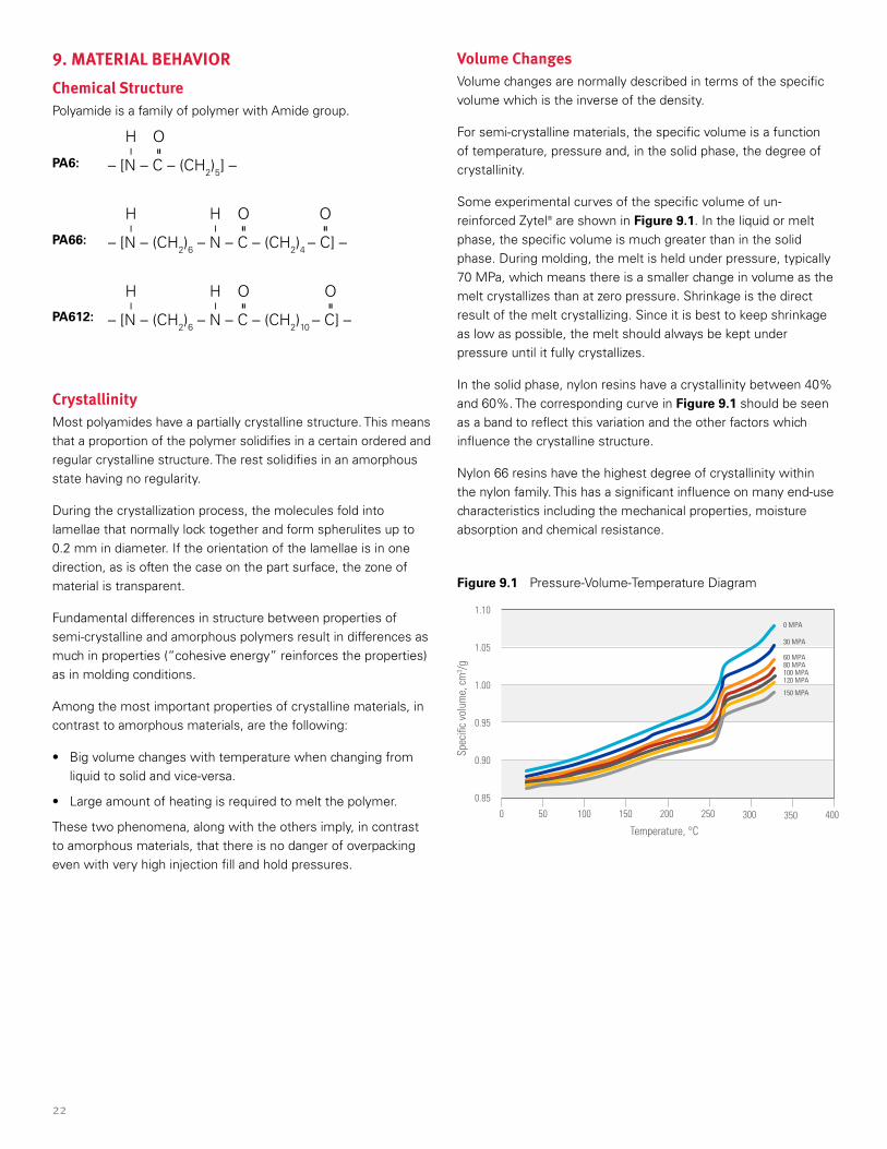
For un-reinforced nylons, the suggested maximum peripheral speed is 0.4 m/s.
For glass-reinforced nylons, the Screw Rotation Speed (RPM) should be low. A maximum of 0.15 m/s peripheral screw speed is suggested in order to minimize glass fiber breakage, and to avoid excessive wear of the screw or the barrel.
The effect of excessive peripheral speed for glass reinforced resins is illustrated in Figure 8.13.
The graph of Figure 8.14 can be used to find the maximum RPM as a function of the screw diameter and of the peripheral speed.
Increasing the screw speed when using a low compression general-purpose screw often results in a decrease in melt temperature. Screws with deep and short metering sections may pump un-melted particles at high screw speeds.
Figure 8.13 Effect of Screw Speed on Impact
Figure 8.14 Screw Speed Versus Screw
Low back pressure should be used. The effect of back pressure is to produce additional screw working which can cause fiber breakage with reduction in physical properties of the molded part. Increasing back pressure increases the work done by the screw on the molten polymer. This could incrementally increase melt temperature and uniformity. Where melt quality is marginal, higher back pressure may reduce un-melted particles, but it will not substantially increase melt quality. Increasing back pressure also increases recovery time.
The lowest possible back pressure consistent with good melt quality is recommended during the molding of DuPont™ Zytel® and Minlon® nylon resins.
Recommended Processing ParametersSpecific processing conditions for any Zytel® and Minlon® PA nylon resins are available on our website.
Zytel® PA Injection Molding Data Table
Minlon® PA nylon Injection Molding Data Table
20 30 40 50 60 70 80 90 100 110 120 130 140 150 160
0
50
100
150
200
250
300
350
400
0
Screw diameter, mm
Revo
lutio
n pe
r min
, rpm
0.40 m/s
0.20 m/s
0.15 m/s
0.10 m/s
0.05 m/s
0.40.30.20.1
60
65
70
75
80
85
90
95
100
0
Perpheral screw speed, m/s
Rete
ntio
n of
impa
ct re
sist
ance
, %
Zytel® unreinforced PA66
22
9. MATERIAL BEHAVIORChemical StructurePolyamide is a family of polymer with Amide group.
PA6:
PA66:
PA612:
CrystallinityMost polyamides have a partially crystalline structure. This means that a proportion of the polymer solidifies in a certain ordered and regular crystalline structure. The rest solidifies in an amorphous state having no regularity.
During the crystallization process, the molecules fold into lamellae that normally lock together and form spherulites up to 0.2 mm in diameter. If the orientation of the lamellae is in one direction, as is often the case on the part surface, the zone of material is transparent.
Fundamental differences in structure between properties of semi-crystalline and amorphous polymers result in differences as much in properties (“cohesive energy” reinforces the properties) as in molding conditions.
Among the most important properties of crystalline materials, in contrast to amorphous materials, are the following:
• Big volume changes with temperature when changing from liquid to solid and vice-versa.
• Large amount of heating is required to melt the polymer.
These two phenomena, along with the others imply, in contrast to amorphous materials, that there is no danger of overpacking even with very high injection fill and hold pressures.
– [N – C – (CH2)5] –
H O— =
– [N – (CH2)6 – N – C – (CH2)4 – C] –
H H O O— — = =
– [N – (CH2)6 – N – C – (CH2)10 – C] –
H H O O— — = =
Volume ChangesVolume changes are normally described in terms of the specific volume which is the inverse of the density.
For semi-crystalline materials, the specific volume is a function of temperature, pressure and, in the solid phase, the degree of crystallinity.
Some experimental curves of the specific volume of un-reinforced Zytel® are shown in Figure 9.1. In the liquid or melt phase, the specific volume is much greater than in the solid phase. During molding, the melt is held under pressure, typically 70 MPa, which means there is a smaller change in volume as the melt crystallizes than at zero pressure. Shrinkage is the direct result of the melt crystallizing. Since it is best to keep shrinkage as low as possible, the melt should always be kept under pressure until it fully crystallizes.
In the solid phase, nylon resins have a crystallinity between 40% and 60%. The corresponding curve in Figure 9.1 should be seen as a band to reflect this variation and the other factors which influence the crystalline structure.
Nylon 66 resins have the highest degree of crystallinity within the nylon family. This has a significant influence on many end-use characteristics including the mechanical properties, moisture absorption and chemical resistance.
Figure 9.1 Pressure-Volume-Temperature Diagram
50 100 200150 250 300 350 400
0.85
0.90
0.95
1.00
1.05
1.10
0
Temperature, °C
Spec
ific
volu
me,
cm
3 /g
0 MPA
30 MPA
60 MPA80 MPA100 MPA120 MPA
150 MPA
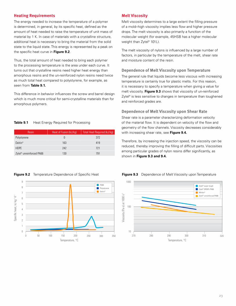
23
Figure 9.2 Temperature Dependence of Specific Heat Figure 9.3 Dependence of Melt Viscosity upon Temperature
Table 9.1 Heat Energy Required for Processing
Heating RequirementsThe energy needed to increase the temperature of a polymer is determined, in general, by its specific heat, defined as the amount of heat needed to raise the temperature of unit mass of material by 1 K. In case of materials with a crystalline structure, additional heat is necessary to bring the material from the solid state to the liquid state. This energy is represented by a peak on the specific heat curve in Figure 9.2.
Thus, the total amount of heat needed to bring each polymer to the processing temperature is the area under each curve. It turns out that crystalline resins need higher heat energy than amorphous resins and the un-reinforced nylon resins need twice as much total heat compared to polystyrene, for example, as seen from Table 9.1.
This difference in behavior influences the screw and barrel design which is much more critical for semi-crystalline materials than for amorphous polymers.
Resin Heat of Fusion (kJ/kg) Total Heat Required (kJ/kg)
Polystyrene 0 372
Delrin® 163 419
HDPE 242 721
Zytel® unreinforced PA66 130 791
Melt ViscosityMelt viscosity determines to a large extent the filling pressure of a mold–high viscosity implies less flow and higher pressure drops. The melt viscosity is also primarily a function of the molecular weight (for example, 45HSB has a higher molecular weight than Zytel® 101L).
The melt viscosity of nylons is influenced by a large number of factors, in particular by the temperature of the melt, shear rate and moisture content of the resin.
Dependence of Melt Viscosity upon TemperatureThe general rule that liquids become less viscous with increasing temperature is certainly true for plastic melts. For this reason, it is necessary to specify a temperature when giving a value for melt viscosity. Figure 9.3 shows that viscosity of un-reinforced Zytel® is less sensitive to changes in temperature than toughened and reinforced grades are.
Dependence of Melt Viscosity upon Shear RateShear rate is a parameter characterizing deformation velocity of the material flow. It is dependent on velocity of the flow and geometry of the flow channels. Viscosity decreases considerably with increasing shear rate, see Figure 9.4.
Therefore, by increasing the injection speed, the viscosity can be reduced, thereby improving the filling of difficult parts. Viscosities among particular grades of nylon resins differ significantly, as shown in Figure 9.3 and 9.4.
50 100 150 200 250 300 350
0
1
2
3
4
5
6
8
7
9
0
Temperature, °C
Spec
ific
heat
, kJ
kg-1 K
-1
PA66
Polystyrene
Delrin®
280 290 300 310 320
10
100
1000
270
Temperature, °C
Visc
osity
(Pa-
s) a
t 100
0 s-1
Zytel® super tough
Zytel® GR30% PA66
Minlon®
Zytel® unreinforced PA66
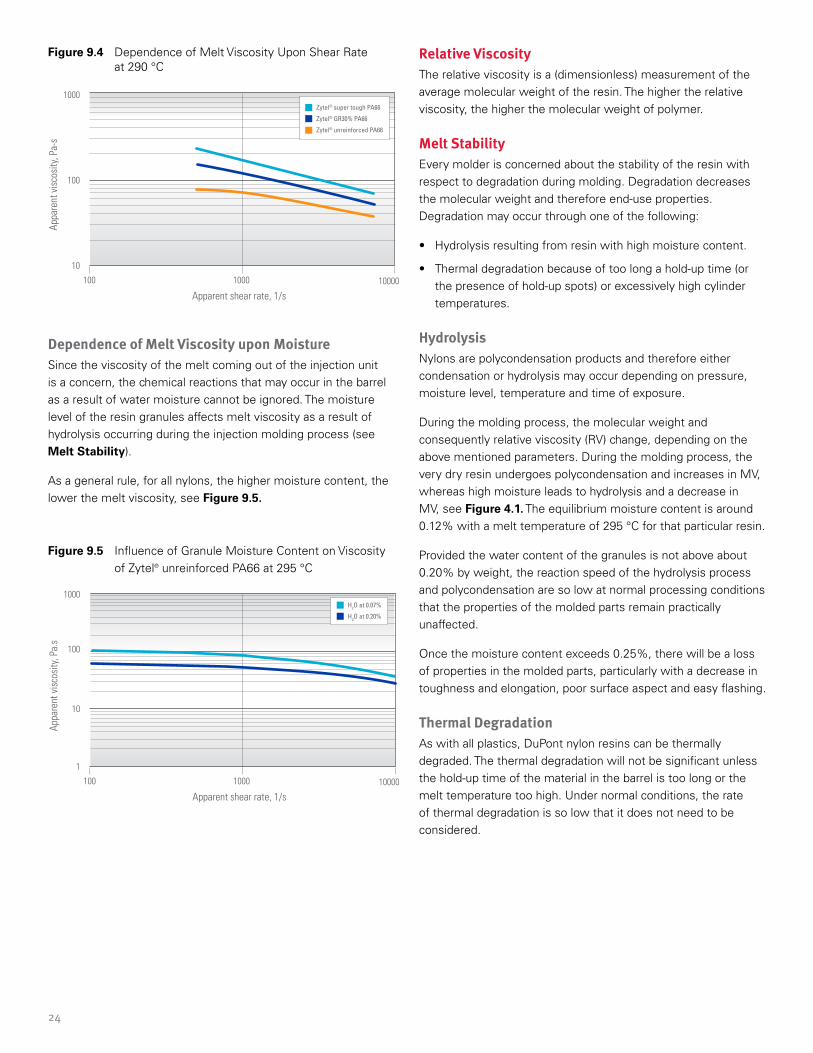
24
Figure 9.4 Dependence of Melt Viscosity Upon Shear Rate at 290 °C
Dependence of Melt Viscosity upon MoistureSince the viscosity of the melt coming out of the injection unit is a concern, the chemical reactions that may occur in the barrel as a result of water moisture cannot be ignored. The moisture level of the resin granules affects melt viscosity as a result of hydrolysis occurring during the injection molding process (see Melt Stability).
As a general rule, for all nylons, the higher moisture content, the lower the melt viscosity, see Figure 9.5.
Figure 9.5 Influence of Granule Moisture Content on Viscosity of Zytel® unreinforced PA66 at 295 °C
Relative Viscosity The relative viscosity is a (dimensionless) measurement of the average molecular weight of the resin. The higher the relative viscosity, the higher the molecular weight of polymer.
Melt StabilityEvery molder is concerned about the stability of the resin with respect to degradation during molding. Degradation decreases the molecular weight and therefore end-use properties. Degradation may occur through one of the following:
• Hydrolysis resulting from resin with high moisture content.
• Thermal degradation because of too long a hold-up time (or the presence of hold-up spots) or excessively high cylinder temperatures.
HydrolysisNylons are polycondensation products and therefore either condensation or hydrolysis may occur depending on pressure, moisture level, temperature and time of exposure.
During the molding process, the molecular weight and consequently relative viscosity (RV) change, depending on the above mentioned parameters. During the molding process, the very dry resin undergoes polycondensation and increases in MV, whereas high moisture leads to hydrolysis and a decrease in MV, see Figure 4.1. The equilibrium moisture content is around 0.12% with a melt temperature of 295 °C for that particular resin.
Provided the water content of the granules is not above about 0.20% by weight, the reaction speed of the hydrolysis process and polycondensation are so low at normal processing conditions that the properties of the molded parts remain practically unaffected.
Once the moisture content exceeds 0.25%, there will be a loss of properties in the molded parts, particularly with a decrease in toughness and elongation, poor surface aspect and easy flashing.
Thermal DegradationAs with all plastics, DuPont nylon resins can be thermally degraded. The thermal degradation will not be significant unless the hold-up time of the material in the barrel is too long or the melt temperature too high. Under normal conditions, the rate of thermal degradation is so low that it does not need to be considered.
1000 10000
10
100
1000
100
Apparent shear rate, 1/s
Appa
rent
vis
cosi
ty, P
a-s
Zytel® super tough PA66
Zytel® GR30% PA66
Zytel® unreinforced PA66
1000 10000
1
10
100
1000
100
Apparent shear rate, 1/s
Appa
rent
vis
cosi
ty, P
a.s
H2O at 0.07%
H2O at 0.20%
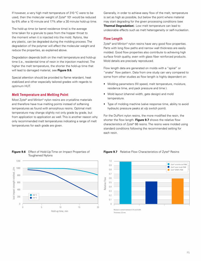
25
Figure 9.6 Effect of Hold-Up Time on Impact Properties of Toughened Nylons
Figure 9.7 Relative Flow Characteristics of Zytel® Resins
If however, a very high melt temperature of 310 °C were to be used, then the molecular weight of Zytel® 101 would be reduced by 6% after a 10 minute and 17% after a 30 minute hold-up time.
The hold-up time (or barrel residence time) is the average time taken for a granule to pass from the hopper throat to the moment when it is injected into the mold. Nylons, like any plastic, can be degraded during the molding process. The degradation of the polymer will affect the molecular weight and reduce the properties, as explained above.
Degradation depends both on the melt temperature and hold-up time (i.e., residential time of resin in the injection machine). The higher the melt temperature, the shorter the hold-up time that will lead to damaged material, see Figure 9.6.
Special attention should be provided to flame retardant, heat stabilized and other especially tailored grades with regards to optimum HUT.
Melt Temperature and Melting PointMost Zytel® and Minlon® nylon resins are crystalline materials and therefore have true melting points instead of softening temperatures as found with amorphous resins. Optimal melt temperature may change slightly not only grade by grade, but from application to application as well. This is another reason why only recommended melt temperatures indicating a range of melt temperatures for each grade are given.
Generally, in order to achieve easy flow of the melt, temperature is set as high as possible, but below the point where material may start degrading for the given processing conditions (see Thermal Degradation). Low melt temperature can lead to undesirable effects such as melt heterogeneity or self-nucleation.
Flow LengthZytel® and Minlon® nylon resins have very good flow properties. Parts with long flow paths and narrow wall thickness are easily molded. Good flow properties also contribute to achieving high surface finish quality, even with glass fiber reinforced products. Mold details are precisely reproduced.
Flow length data are generated on molds with a “spiral” or “snake” flow pattern. Data from one study can vary compared to some from other studies as flow length is highly dependent on:
• Molding parameters (fill speed, melt temperature, moisture, residence time, and pack pressure and time ).
• Mold layout (channel width, gate design) and mold temperature.
• Type of molding machine (valve response time, ability to avoid hydraulic pressure peaks at v/p switch point).
For the DuPont nylon resins, the more modified the resin, the shorter the flow length. Figure 9.7 shows the relative flow characteristics of Zytel® 66 resins. The resins were molded using standard conditions following the recommended setting for each resin.
2015105
200
0
400
600
800
1000
1200
0
Hold-up time, min
Izod
impa
ct s
treng
th n
otch
ed, J
/m
280 °C
310 °C0.2
0.1
0.3
0.4
0.5
0.6
0.7
0.9
1.0
0.8
0
Rela
tive
Flow
Zytel® unreinforced PA66
Zytel® super tough PA66
Zytel® GR30% PA66
Moisture content between 0.15 and 0.20%
Thickness: 2.5 mm
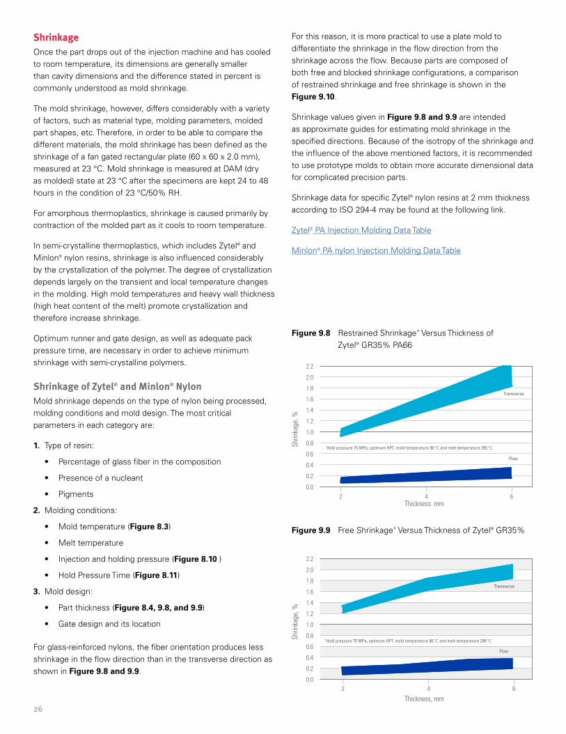
26
ShrinkageOnce the part drops out of the injection machine and has cooled to room temperature, its dimensions are generally smaller than cavity dimensions and the difference stated in percent is commonly understood as mold shrinkage.
The mold shrinkage, however, differs considerably with a variety of factors, such as material type, molding parameters, molded part shapes, etc. Therefore, in order to be able to compare the different materials, the mold shrinkage has been defined as the shrinkage of a fan gated rectangular plate (60 x 60 x 2.0 mm), measured at 23 °C. Mold shrinkage is measured at DAM (dry as molded) state at 23 °C after the specimens are kept 24 to 48 hours in the condition of 23 °C/50% RH.
For amorphous thermoplastics, shrinkage is caused primarily by contraction of the molded part as it cools to room temperature.
In semi-crystalline thermoplastics, which includes Zytel® and Minlon® nylon resins, shrinkage is also influenced considerably by the crystallization of the polymer. The degree of crystallization depends largely on the transient and local temperature changes in the molding. High mold temperatures and heavy wall thickness (high heat content of the melt) promote crystallization and therefore increase shrinkage.
Optimum runner and gate design, as well as adequate pack pressure time, are necessary in order to achieve minimum shrinkage with semi-crystalline polymers.
Shrinkage of Zytel® and Minlon® NylonMold shrinkage depends on the type of nylon being processed, molding conditions and mold design. The most critical parameters in each category are:
1. Type of resin:
• Percentage of glass fiber in the composition
• Presence of a nucleant
• Pigments
2. Molding conditions:
• Mold temperature (Figure 8.3)
• Melt temperature
• Injection and holding pressure (Figure 8.10 )
• Hold Pressure Time (Figure 8.11)
3. Mold design:
• Part thickness (Figure 8.4, 9.8, and 9.9)
• Gate design and its location
For glass-reinforced nylons, the fiber orientation produces less shrinkage in the flow direction than in the transverse direction as shown in Figure 9.8 and 9.9.
For this reason, it is more practical to use a plate mold to differentiate the shrinkage in the flow direction from the shrinkage across the flow. Because parts are composed of both free and blocked shrinkage configurations, a comparison of restrained shrinkage and free shrinkage is shown in the Figure 9.10.
Shrinkage values given in Figure 9.8 and 9.9 are intended as approximate guides for estimating mold shrinkage in the specified directions. Because of the isotropy of the shrinkage and the influence of the above mentioned factors, it is recommended to use prototype molds to obtain more accurate dimensional data for complicated precision parts.
Shrinkage data for specific Zytel® nylon resins at 2 mm thickness according to ISO 294-4 may be found at the following link.
Zytel® PA Injection Molding Data Table
Minlon® PA nylon Injection Molding Data Table
Figure 9.8 Restrained Shrinkage* Versus Thickness of Zytel® GR35% PA66
Figure 9.9 Free Shrinkage* Versus Thickness of Zytel® GR35%
0.2
0.0
0.4
0.6
0.8
1.0
2.2
2.0
1.8
1.6
1.4
1.2
Thickness, mm
Shrin
kage
, %
*Hold pressure 75 MPa, optimum HPT, mold temperature 90 °C and melt temperature 295 °C
642
Transverse
Flow
642
0.2
0.0
0.4
0.6
0.8
1.0
2.2
2.0
1.8
1.6
1.4
1.2
Thickness, mm
Shrin
kage
, %
*Hold pressure 75 MPa, optimum HPT, mold temperature 90 °C and melt temperature 295 °C
Transverse
Flow
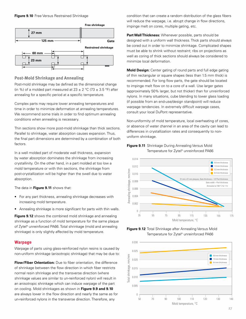
27
Figure 9.11 Shrinkage During Annealing Versus Mold Temperature for Zytel® unreinforced PA66
Figure 9.10 Free Versus Restrained Shrinkage
Figure 9.12 Total Shrinkage after Annealing Versus Mold Temperature for Zytel® unreinforced PA66
Post-Mold Shrinkage and AnnealingPost-mold shrinkage may be defined as the dimensional change (in %) of a molded part measured at 23 ± 2 °C (73 ± 3.5 °F) after annealing for a specific period at a specific temperature.
Complex parts may require lower annealing temperatures and time in order to minimize deformation at annealing temperatures. We recommend some trials in order to find optimum annealing conditions when annealing is necessary.
Thin sections show more post-mold shrinkage than thick sections. Parallel to shrinkage, water absorption causes expansion. Thus, the final part dimensions are determined by a combination of both factors.
In a well molded part of moderate wall thickness, expansion by water absorption dominates the shrinkage from increasing crystallinity. On the other hand, in a part molded at too low a mold temperature or with thin sections, the shrinkage from post-crystallization will be higher than the swell due to water absorption.
The data in Figure 9.11 shows that:
• For any part thickness, annealing shrinkage decreases with increasing mold temperature.
• Annealing shrinkage is more significant for parts with thin walls.
Figure 9.12 shows the combined mold shrinkage and annealing shrinkage as a function of mold temperature for the same plaque of Zytel® unreinforced PA66. Total shrinkage (mold and annealing shrinkage) is only slightly affected by mold temperature.
WarpageWarpage of parts using glass-reinforced nylon resins is caused by non-uniform shrinkage (anisotropic shrinkage) that may be due to:
Flow/Fiber Orientation: Due to fiber orientation, the difference of shrinkage between the flow direction in which fiber restricts normal resin shrinkage and the transverse direction (where shrinkage values are similar to un-reinforced nylon) will result in an anisotropic shrinkage which can induce warpage of the part on cooling. Mold shrinkages as shown in Figure 9.9 and 9.10 are always lower in the flow direction and nearly the same as for un-reinforced nylons in the transverse direction. Therefore, any
condition that can create a random distribution of the glass fibers will reduce the warpage, i.e. abrupt change in flow directions, impinge melt on cores, multiple gating, etc.
Part Wall Thickness: Whenever possible, parts should be designed with a uniform wall thickness. Thick parts should always be cored out in order to minimize shrinkage. Complicated shapes must be able to shrink without restraint; ribs on projections as well as coring of thick sections should always be considered to minimize local deformation.
Mold Design: Center gating of round parts and full edge gating of thin rectangular or square shapes (less than 1.5 mm thick) is recommended. For long flow parts, the gate should be located to impinge melt flow on to a core of a wall. Use larger gates (approximately 50% larger, but not thicker) than for unreinforced nylons. In many situations, cube blending to lower glass loading (if possible from an end-use/design standpoint) will reduce warpage tendencies. In extremely difficult warpage cases, consult your local DuPont representative.
Non-uniformity of mold temperature, local overheating of cores, or absence of water channel in an area of the cavity can lead to differences in crystallization rates and consequently to non-uniform shrinkage.
55 75 95 115 135 155 175
0
0.002
0.004
0.006
0.008
0.010
0.012
0.014
35
Mold temperature, °C
Anne
alin
g sh
rinka
ge, m
m/m
m
0.8 mm thickness
1.6 mm thickness
3.2 mm thickness
6.4 mm thickness
51 mm x 51 mm plaques, Gate thickness = 1/2 Part thickness
Gate width = Part thickness
Annealed at 163 °C for 1 hr
70 90 100 110 120 130 140
0
0.005
0.010
0.015
0.020
0.025
0.030
50
Mold temperature, °C
Tota
l shr
inka
ge, m
m/m
m 0.8 mm thickness
1.6 mm thickness
6.4 mm thickness
Free shrinkage
Restrained shrinkage
125 mm
60 mm
27 mm
23 mm
Gate
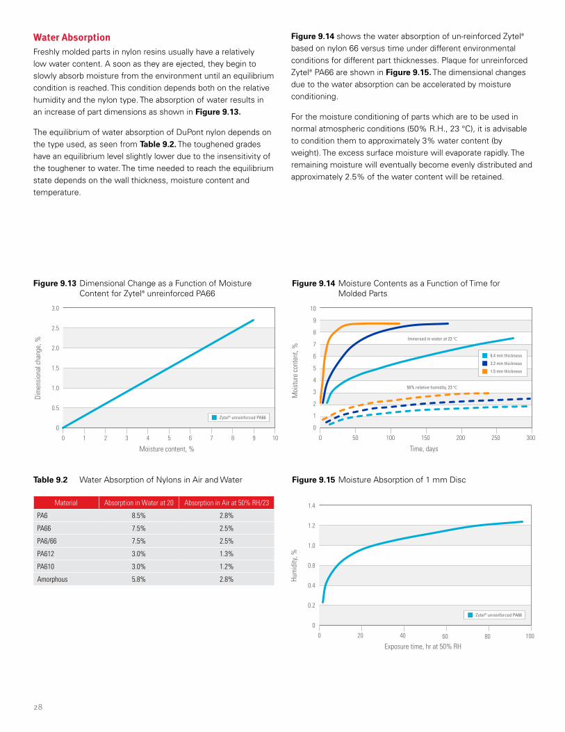
28
Water AbsorptionFreshly molded parts in nylon resins usually have a relatively low water content. A soon as they are ejected, they begin to slowly absorb moisture from the environment until an equilibrium condition is reached. This condition depends both on the relative humidity and the nylon type. The absorption of water results in an increase of part dimensions as shown in Figure 9.13.
The equilibrium of water absorption of DuPont nylon depends on the type used, as seen from Table 9.2. The toughened grades have an equilibrium level slightly lower due to the insensitivity of the toughener to water. The time needed to reach the equilibrium state depends on the wall thickness, moisture content and temperature.
Figure 9.13 Dimensional Change as a Function of Moisture Content for Zytel® unreinforced PA66
Figure 9.14 Moisture Contents as a Function of Time for Molded Parts
Figure 9.15 Moisture Absorption of 1 mm Disc Table 9.2 Water Absorption of Nylons in Air and Water
Material Absorption in Water at 20 Absorption in Air at 50% RH/23
PA6 8.5% 2.8%
PA66 7.5% 2.5%
PA6/66 7.5% 2.5%
PA612 3.0% 1.3%
PA610 3.0% 1.2%
Amorphous 5.8% 2.8%
Figure 9.14 shows the water absorption of un-reinforced Zytel® based on nylon 66 versus time under different environmental conditions for different part thicknesses. Plaque for unreinforced Zytel® PA66 are shown in Figure 9.15. The dimensional changes due to the water absorption can be accelerated by moisture conditioning.
For the moisture conditioning of parts which are to be used in normal atmospheric conditions (50% R.H., 23 °C), it is advisable to condition them to approximately 3% water content (by weight). The excess surface moisture will evaporate rapidly. The remaining moisture will eventually become evenly distributed and approximately 2.5% of the water content will be retained.
50 100 150 200 250 300
0
1
2
3
4
5
6
8
7
9
10
0
Time, days
Moi
stur
e co
nten
t, %
6.4 mm thickness
3.2 mm thickness
1.5 mm thickness
Immersed in water at 23 °C
50% relative humidity, 23 °C
20 40 8060 100
0
0.2
0.4
0.8
1.0
1.2
1.4
0
Exposure time, hr at 50% RH
Hum
idity
, %
Zytel® unreinforced PA66
1 2 3 4 5 7 8 96 10
0
0.5
1.0
1.5
2.0
2.5
3.0
0
Moisture content, %
Dim
ensi
onal
cha
nge,
%
Zytel® unreinforced PA66
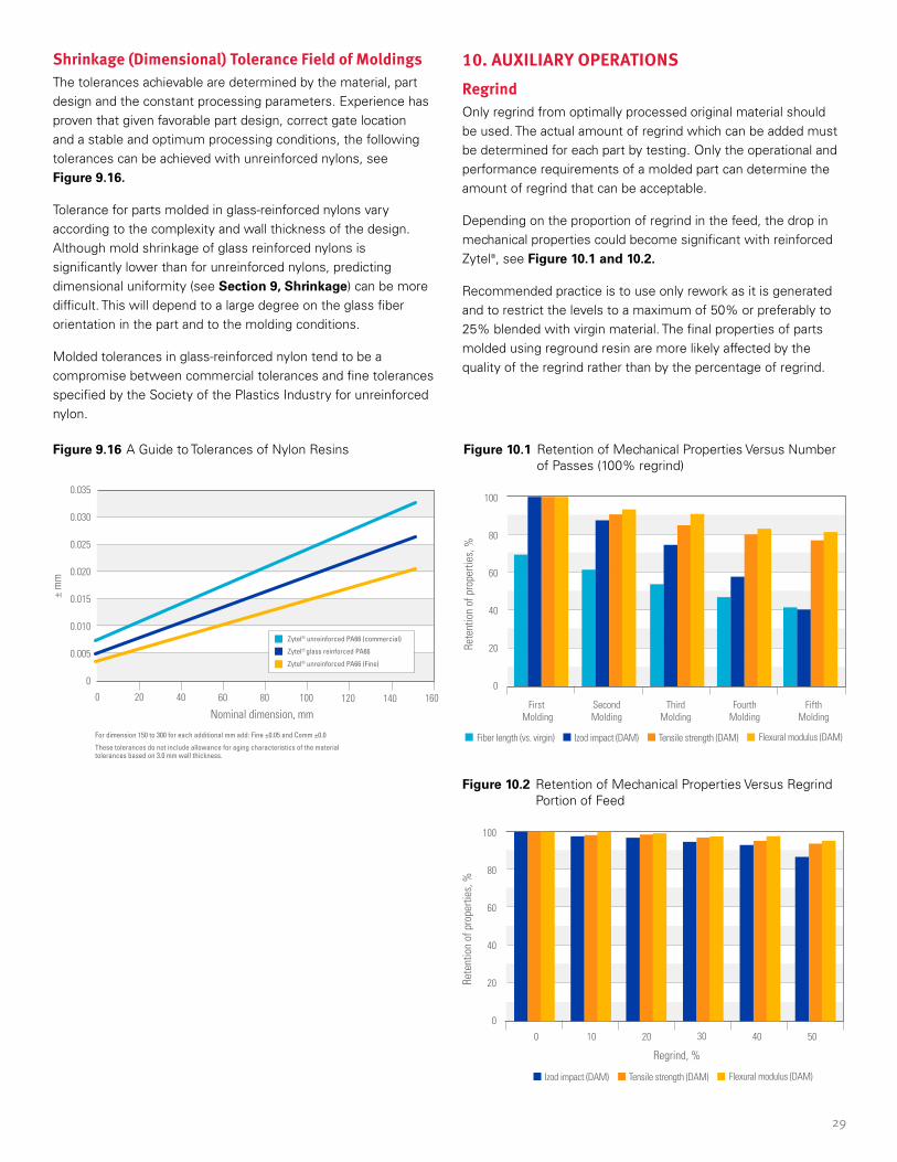
29
Figure 10.1 Retention of Mechanical Properties Versus Number of Passes (100% regrind)
Figure 9.16 A Guide to Tolerances of Nylon Resins
Figure 10.2 Retention of Mechanical Properties Versus Regrind Portion of Feed
Shrinkage (Dimensional) Tolerance Field of MoldingsThe tolerances achievable are determined by the material, part design and the constant processing parameters. Experience has proven that given favorable part design, correct gate location and a stable and optimum processing conditions, the following tolerances can be achieved with unreinforced nylons, see Figure 9.16.
Tolerance for parts molded in glass-reinforced nylons vary according to the complexity and wall thickness of the design. Although mold shrinkage of glass reinforced nylons is significantly lower than for unreinforced nylons, predicting dimensional uniformity (see Section 9, Shrinkage) can be more difficult. This will depend to a large degree on the glass fiber orientation in the part and to the molding conditions.
Molded tolerances in glass-reinforced nylon tend to be a compromise between commercial tolerances and fine tolerances specified by the Society of the Plastics Industry for unreinforced nylon.
10. AUXILIARY OPERATIONSRegrindOnly regrind from optimally processed original material should be used. The actual amount of regrind which can be added must be determined for each part by testing. Only the operational and performance requirements of a molded part can determine the amount of regrind that can be acceptable.
Depending on the proportion of regrind in the feed, the drop in mechanical properties could become significant with reinforced Zytel®, see Figure 10.1 and 10.2.
Recommended practice is to use only rework as it is generated and to restrict the levels to a maximum of 50% or preferably to 25% blended with virgin material. The final properties of parts molded using reground resin are more likely affected by the quality of the regrind rather than by the percentage of regrind.
20 40 60 80 100 120 140 160
0
0.005
0.010
0.015
0.020
0.025
0.030
0.035
0
Nominal dimension, mm
± m
m
Zytel® unreinforced PA66 (commercial)
Zytel® glass reinforced PA66
Zytel® unreinforced PA66 (Fine)
For dimension 150 to 300 for each additional mm add: Fine ±0.05 and Comm ±0.0
These tolerances do not include allowance for aging characteristics of the material tolerances based on 3.0 mm wall thickness.
First Molding
SecondMolding
ThirdMolding
FourthMolding
FifthMolding
0
20
40
60
80
100
Rete
ntio
n of
pro
perti
es, %
Fiber length (vs. virgin) Tensile strength (DAM) Flexural modulus (DAM)Izod impact (DAM)
0 10 20 4030 50
0
20
40
60
80
100
Rete
ntio
n of
pro
perti
es, %
Regrind, %
Tensile strength (DAM) Flexural modulus (DAM)Izod impact (DAM)
30
To use regrind successfully, the following principles should be kept in mind:
1. Regrind absorbs more moisture, and faster, than virgin resin and therefore:
• Protect the reground material from moisture. Keep it in sealed moisture proof containers.
• Sprues and runners should be reground, mixed and used as soon as they are removed from the machine, thus avoiding an extra drying operation.
• Before processing, the regrind should be dried to avoid the possibility of degradation due to the presence of moisture.
2. Regrind may contain significantly more contaminants than virgin material, and therefore:
• Make sure reground material is free of contamination.
• Minimize the handling of sprues and runners; use lint-free gloves.
3. Only regrind from optimally processed original material should be used:
• Do not use molded parts and runners that are discolored or splayed. These may be indications that the resin has been degraded.
• Do not use material that has been previously degraded because of high moisture content and/or too long residence time in the barrel. Molded parts that become brittle as a result of poor material handling (too high moisture content in the granules) or material left in the barrel (too long residence time) must be discarded and not re-used. This avoids any dramatic deterioration of properties if it were mixed with good regrind and/or virgin resin.
4. Keep the particle size of the reground material uniform. Reground material should have approximately the same size as fresh pellets or fresh granules. Grinder screens with a mesh size of about 5 mm (0.2 in) yield a grain size of approximately 3 mm (0.12 in) in diameter.
Remove and avoid fine particles in reground materials. Fine particles rapidly absorb moisture that can plug the filters on vacuum loaders. A screen with a mesh of approximately 2.5 mm (0.1 in) can be used for removing fine particles in the regrind.
In the case of parts subjected to mechanical loads, regrind should be used only rarely. A higher amount of regrind is feasible, for example, when, in addition to electrical insulating properties, the part needs only a high heat deflection temperature.
Last, the actual amount of regrind which can be added must be determined for each part by testing. Only the operational and performance requirements of a molded part can determine the amount of regrind that is acceptable.
ColoringA range of cube-blended standard colors is available for certain polyesters. The freedom of design is even greater in that almost any coloring system can be used: dry pigment, paste, liquid color or dyes. Such systems can also lead to variations in properties and/or performance.
When using master-batch or dry pigments, special attention should be given to these aspects:
• The dry pigment or master-batch has to be chemically compatible with base resin, in this case polyamide, and must have good thermal stability above the processing temperature of the resin.
• Pigments usually affect the crystallization rate and consequently the shrinkage. Additionally, the carrier of liquid colors has an effect on molding.
• The carrier can be considered as a surface lubricant which may, theoretically, cause screw slippage leading to screw feed and/or filling problems.
• The key issue when adding color during molding is to ensure a homogeneous dispersion and mixing of the pigment in the polymer matrix.
When adding color during molding, one should observe the following points carefully:
• Use of a reasonable ratio between polymer and master-batch.
• Ideally, use a screw with a mixing head or, alternately, use of a high-compression screw.
• Use of a screw retraction stroke less than 30% of the maximum screw retraction of the machine.
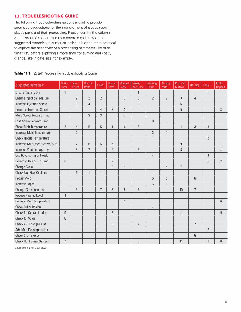
31
11. TROUBLESHOOTING GUIDEThe following troubleshooting guide is meant to provide prioritized suggestions for the improvement of issues seen in plastic parts and their processing. Please identify the column of the issue of concern and read down to each row of the suggested remedies in numerical order. It is often more practical to explore the sensitivity of a processing parameter, like pack time first, before exploring a more time consuming and costly change, like in gate size, for example.
Suggested Remedies* Brittle Parts
Short Shots
Voids in Parts Sinks Burned
PartsWarped Parts
Weak Knit lines
Sticking Sprue
Sticking Parts
Poor Part Surface Flashing Drool Mold
Deposit
Ensure Resin is Dry 1 1 1 1
Change Injection Pressure 2 2 2 2 5 2 2 3 4
Increase Injection Speed 3 4 2 6
Decrease Injection Speed 4 3 3 5 3
More Screw Forward Time 3 3 7
Less Screw Forward Time 8 3
Check Melt Temperature 2 4 5 5 1 6 6 4 3 3 1
Increase Mold Temperature 5 3 1 1
Check Nozzle Temperature 1 2
Increase Gate (feed system) Size 7 6 6 5 9 7
Increase Venting Capacity 6 7 2 3 8 4
Use Reverse Taper Nozzle 4 4
Decrease Residence Time 3 7 5 2
Change Cycle 4 4 4 7
Check Pad Size (Cushion) 1 1 1
Repair Mold 5 5 6
Increase Taper 6 6
Change Gate Location 8 7 6 5 7 10 7
Reduce Regrind Level 4
Balance Mold Temperature 1 6
Check Puller Design 7
Check for Contamination 5 8 2 5
Check for Voids 6
Check V-P Change Point 9 4 2
Add Melt Decompression 7
Check Clamp Force 5
Check Hot Runner System 7 8 11 6 8
Table 11.1 Zytel® Processing Troubleshooting Guide
*Suggested to try in order shown

The information provided in this data sheet corresponds to DuPont knowledge on the subject at the date of its publication. This information may be subject to revision as new knowledge and experience becomes available. The data provided fall within the normal range of product properties and relate only to the specific material designated; these data may not be valid for such material used in combination with any other materials, additives or pigments or in any process, unless expressly indicated otherwise.
The data provided should not be used to establish specification limits or used alone as the basis of design; they are not intended to substitute for any testing you may need to conduct to determine for yourself the suitability of a specific material for your particular purposes. Since DuPont cannot anticipate all variations in actual end-use and disposal conditions, DuPont does not guarantee results, makes no warranties and assumes no liability in connection with any use of this information. All such information is given and accepted at the buyer’s risk. It is intended for use by persons having technical skill, at their own discretion and risk. Nothing in this publication is to be considered as a license to operate under or a recommendation to infringe any patent.
CAUTION: Do not use DuPont materials in medical applications involving implantation in the human body or contact with internal body fluids or tissues unless the material has been provided from DuPont under a written contract that is consistent with DuPont policy regarding medical applications and expressly acknowledges the contemplated use. For further information, please contact your DuPont representative. You may also request a copy of DuPont POLICY Regarding Medical Applications H-50103-5 and DuPont CAUTION Regarding Medical Applications H-50102-5.
2017 Copyright © DuPont. The DuPont Oval Logo, DuPont™ ,Zytel® and Minlon® are trademarks or registered trademarks of E.I. du Pont de Nemours and Company or its affiliates. All rights reserved.
(05/17) GNE-A11218-00-A1216
Visit us at plastics.dupont.com or zytel.dupont.com
Contact DuPont at the following regional locations:
North America +1-302-999-4592
Greater China +86-400-8851-888
Latin America +0800 17 17 15
Japan +81-3-5521-8600
Europe, Middle East, Africa +41 22 717 51 11
ASEAN +65 6586 3688