Embed Size (px)
Citation preview

DULCOMETER®
Multi-parameter Controller diaLog DACa
Software manual
A2100Valid only in combination with the oper‐ating instructions for the Multi-param‐eter Controller diaLog DACa.
Modbus RTU
EN
Target group: trained electronics technicians984163 BA DM 212 12/15 EN
Please carefully read these operating instructions before use. · Do not discard.The operator shall be liable for any damage caused by installation or operating errors.
The latest version of the operating instructions are available on our homepage.

General non-discriminatory approach In order to make it easier to read, thisdocument uses the male form in grammat‐ical structures but with an implied neutralsense. It is aimed equally at both men andwomen. We kindly ask female readers fortheir understanding in this simplification ofthe text.
Supplementary information
Please read the supplementary information in its entirety.
Information
This provides important information relating to the correct operation of the unit or isintended to make your work easier.
Safety Information
The safety notes include detailed descriptions of the hazardous situation.
The following symbols are used to highlight instructions, links, lists, results and other ele‐ments in this document:
More symbols
Symbol Description
Action, step by step
⇨ Outcome of an action
Links to elements or sections of these instructions or other applicabledocuments
n List without set order
[Taster] Display element (e.g. indicators)
Operating element (e.g. button, switch)
‘Display /GUI’ Screen elements (e.g. buttons, assignment of function keys)
CODE Presentation of software elements and/or texts
Supplemental instructions
2

Table of contents1 Modbus RTU Implementation................................................................................. 4
1.1 Modbus RTU Message Structure................................................................... 51.2 Modbus RTU Link Layer [Link Layer]............................................................. 51.3 Serial Connections......................................................................................... 61.4 Modbus Connection Terminals....................................................................... 71.5 IEEE 32 bit floating point register................................................................... 81.6 Supported Modbus commands...................................................................... 81.7 Register-Addresses-Numbering..................................................................... 91.8 Standard-Connection-Settings..................................................................... 101.9 Overview of the controller registers ............................................................. 11
2 Bit field value........................................................................................................ 182.1 Status of the channel.................................................................................... 192.2 Error of the channel...................................................................................... 202.3 Warning of the channel................................................................................ 222.4 Potential-free relay....................................................................................... 232.5 Settings of the channel configuration........................................................... 242.6 CRC-16 calculation...................................................................................... 25
Table of contents
3

1 Modbus RTU ImplementationThis document contains general informa‐tion regarding the implementation of theProMinent diaLog Controller into the serialcommunication protocol of the ModbusRTU.
The ProMinent diaLog Controller acts as aslave device [Device 1].Communication between the ProMinentdiaLog Controllers [Device 1] and externalmaster devices [Device 0] is possible,including e.g. PLC or PC.
The Modbus protocol is a communicationprotocol that enables devices to use datavia a joint connection if the devices com‐municate with each other via the ModbusRTY RS-485 or RS-232 specification.
The diaLog Controller does not emulateevery type of MODICON device.
The Modbus RTU specification describesthe data link layer and the physical layer.
The notification structure of the functioncodes uses the Modbus RTU standards.
The IEEE 32 bit floating point numbersand integers [Integer] are used.
Default settingsThe ProMinent diaLog Controller isdelivered to the customer with prede‐termined settings, with the [address 1]and a baud rate of 19200 baudYou can set the slave address andthe baud rate in the ProMinent diaLogController via the set-up menu.
The implementation of the Modbus inter‐face is based on the following standards:
n www.modbus.org/docs/Modbus_over_serial_line_V1_02.pdf
More information about Modbus can befound at www.modbus.org or other web‐sites belonging to your (local) Modbusorganisation in your country (if available).
Modbus RTU Implementation
4

1.1 Modbus RTU Message Structure
Parameter Value
Standard RS-485 (preset) or RS-232
Coding system 8 bit
Broadcast support Yes
Number of data bits per character 10 / 11 bits:
1 start bit
8 data bits
0 / 1 parity bits [no, odd, even]
1 / 2 stop bits (required 2 stop bits if no paritybit is used)
predetermined value: [8O1]
Data rate (baud) 2400, 4800, 9600, 19200 (predeterminedvalue), 38400, 57600, 115200
Error check CRC-16 [cyclic redundancy check]; polyno‐mial = 0x0A001 (1010000000000001)
Multi-byte transmission byte sequence
0x1234 transfers 0x12 followed by 0x34Message [TIMEOUT] >= 3,5 characters (> 2 ms at a baud rate ≧
19200)
Slave address 1 ... 247 (1 is preset)
1.2 Modbus RTU Link Layer[Link Layer]
The link layer [Link Layer] comprises thefollowing features:
n Slave address identificationn Start / end identificationn CRC-16 creation / checkn Buffer overflow detectionn Unused line detection
n Sending / receiving time limit for mes‐sages
n Raster setting error detection
Errors in messages that are received bythe physical layer of the slave and are rec‐ognised, are ignored. The physical layer isrestarted automatically if a new messageis detected on the unused line.
Modbus RTU Implementation
5

1.3 Serial ConnectionsThe ProMinent diaLog Modbus interfacesupports the following interface standards:
RS-485 (TIA-485-A)
n Half-duplex, 2-wire technology,twisted pair cable [twisted pair]
n Differential voltage level ± 5 V.n Cable length up to 1200 mn Active termination.
RS-232 (TIA-232-F)
n Asynchronous serial transmissionwith voltages between -15 V ... +15 V.
The active cable termination and the inter‐face mode can be changed via the ProMi‐nent diaLog menu (SETUP > BUS config‐uration). The RS-485 mode is thepredetermined interface.
Modbus RTU Implementation
6

1.4 Modbus Connection Terminals
If the interface is configured in the RS-485 mode and the diaLog controller is an end‐point slave, the active termination must be activated in the control menu.
A2122
Fig. 1: Modbus Connection TerminalsThe diaLog Modbus RTU interface offers two connection terminals for the Modbuscabling.
The connection pins are connected electrically as follows: 1 = 1, 2 = 2; 3 = 3.
Modbus RTU Implementation
7

The device can be connected as an endpoint slave (either with one of the connections) oras [Daisy-Chain-Slave] (with both connections).
1.5 IEEE 32 bit floating point register
A2123
Fig. 2: Example of an IEEE 32 bit floating point registerThe ProMinent diaLog Modbus interface uses the IEEE 754 format for 32 bit floatingpoint values (with single precision).
1.6 Supported Modbus commandsThe ProMinent diaLog Modbus interface supports the following commands:
Command Function code Maximum register numberin one transaction
Read-Holding-Register 0x03 (3) 125
Write-Single-Register 0x06 (6) 1
Write-Multiple-Register 0x10 (16) 123
Read / Write-Multiple-Reg‐ister
0x17 (23) 125 read / 121 write
Not all registers support all commands. Read-Only-Register [Read-only] can be onlycalled up with function code 3.
Maximum message sizeThe maximum message size for the read-holding-register function[Read Holding Registers] is 100 byte with 9600 baud (200 byte at 19200 baud and400 byte at 38400 baud). If this size is exceeded, the possibly damaged replies maybe received.
Modbus RTU Implementation
8

Register 199Register 199 can be used to test the byte interpretation corrected by the master formulti-byte values. [Device 0]
n If one of the writing registers triggers an exception, the value for all subsequent reg‐isters is ignored.
n If a byte parameter is read, the top 8 bit of the Modbus register become 0. If a byteparameter is written, the top 8 bit of the Modbus register must be set to 0.
n Long integer parameters [Long-Integer-Parameter] are 4 bytes long and are illus‐trated in two subsequent Modbus registers. The first register contains the bits 32 to16. The second register contains the bits 15 to 0.
n Floating point parameters are 4 bytes long and are illustrated in two subsequentModbus registers. Floating points are illustrated with simple precision IEEE format (1sign bit, 8 bit exponent and 23 bit fraction). The first register contains the bits 32 to16. The second register contains the bits 15 to 0.
1.7 Register-Addresses-Num‐bering
Maximum PDU sizeThe maximum PDU size is 253 bytes.
The register addresses numbering devi‐ates from the Modbus RTU PDU num‐bering.
The Modbus PDU register address is reg‐ister address 1.
The ProMinent diaLog register 100 iscalled up from a PDU address 99.
Modbus RTU Implementation
9

1.8 Standard-Connection-Settings
Access code [Service]The access codes must be used to change these settings. [Service]
This is the standard configuration ex factory for the ProMinent diaLog Modbus interface
Parameter Standard value
Serial mode RS-485 differential [differential]
Termination [Termination] Disabled [disabled ]
Serial format 8 data bits
Odd parity [Odd parity]1 stop bit
(801)
Baud rate 19200 Baud
Slave address 1
The configuration can be modified in the menu of the diaLog controller via[SETUP > BUS-CONFIGURATION] .
Modbus RTU Implementation
10

1.9 Overview of the controller registersThese tables contain the ProMinent diaLog register overview
PDUAddress
(hex)
Register
(decimal)
Parameter name Format Access
R = Read
W = Write
Info
Outgoing data channel 1 / [Outgoing Data Channel 1]
63 100 Actual MeasuredValue
FLOAT32 R
65 102 ControllerActuating Value
INT16 R [%]
66 103 Temperature INT16 R [0.1°C]
67 104 Actual Set Point FLOAT32 R
69 106 Actual ExternalDisturbanceValue
UINT16 R [%]
6A 107 Status UINT16 R Bit coded
6B 108 Warnings UINT16 R Bit coded
6C 109 Actual ExistingErrors
UINT32 R Bit coded
6E 111 ActualUnconfirmedErrors
UINT32 R Bit coded
Outgoing data channel 2 / [Outgoing Data Channel 2]
70 113 Actual MeasuredValue
FLOAT32 R
72 115 ControllerActuating Value
INT16 R [%]
1: For use at a later point2: For use at a later point
Modbus RTU Implementation
11

PDUAddress
(hex)
Register
(decimal)
Parameter name Format Access
R = Read
W = Write
Info
73 116 Temperature UINT16 R [0.1°C]
74 117 Actual Set Point FLOAT32 R
76 119 Actual ExternalDisturbanceValue
UINT16 R [%]
77 120 Status UINT16 R Bit coded
78 121 Warnings UINT16 R Bit coded
79 122 Actual ExistingErrors
UINT32 R Bit coded
7B 124 ActualUnconfirmedErrors
UINT32 R Bit coded
Outgoing data mathematic channel / [Outgoing Data Mathematic Channel]
7D 126 Actual MeasuredValue
FLOAT32 R
7F 128 Status UINT16 R
80 129 Warnings UINT16 R Bit coded
81 130 Actual ExistingErrors[1]
UINT16 R Bit coded
82 131 ActualUnconfirmedErrors[2]
UINT16 R Bit coded
Hardware-Status / [Hardware State]
83 132 Current Output 1 UINT16 R [0.1 mA]
84 133 Current Output 2 UINT16 R [0.1 mA]1: For use at a later point2: For use at a later point
Modbus RTU Implementation
12

PDUAddress
(hex)
Register
(decimal)
Parameter name Format Access
R = Read
W = Write
Info
85 134 Current Output 3 UINT16 R [0.1 mA]
86 135 Dry ContactRelay
UINT16 R Bit coded
87 136 Pump Relay 1(MosFET)
UINT16 R Pulses /min
88 137 Pump Relay 2(MosFET)
UINT16 R Pulses /min
89 138 Pump Relay 3(MosFET)
UINT16 R Pulses /min
90 139 Pump Relay 4(MosFET)
UINT16 R Pulses /min
Device information / [Device Information]
8B 140 Firmware UINT32 R
8D 142 Firmware Channel2
UINT32 R
8F 144 Firmware ModbusInterface
UINT32 R
91 146 Serial number UINT32 R
93 148 Revision UINT16 R
94 149 Revision Channel2
UINT16 R
95 150 Identity code [0-3]UINT32 R
97 152 Identity code [4-7]UINT32 R
99 154 Identity code[8-11]
UINT32 R
1: For use at a later point2: For use at a later point
Modbus RTU Implementation
13

PDUAddress
(hex)
Register
(decimal)
Parameter name Format Access
R = Read
W = Write
Info
9B 156 Identity code[12-15]
UINT32 R
9D 158 Identity code[16-19]
UINT32 R
9F 160 Identity code[20-23]
UINT32 R
C5 198 Endian TestValue
UINT32 R 0xAABBCCDD
Control channel 1 / [Control Channel 1]
C7 200 Stop UINT16 R/W Stop =0xFFFF
C8 201 Pause UINT16 R/W 1=Pause2=Pause/HOLD
Control channel 2 /[Control Channel 2]
C9 202 Stop UINT16 R/W Stop =0xFFFF
CA 203 Pause UINT16 R/W 1=Pause
2=Pause/[HOLD]
1: For use at a later point2: For use at a later point
Modbus RTU Implementation
14

PDUAddress
(hex)
Register
(decimal)
Parameter name Format Access
R = Read
W = Write
Info
Configuration channel 1 / [Control Channel 1]
CB 204 Configuration UINT16 R/W Bit coded
CC 205 Remote Set Point FLOAT32 R/W
CE 207 Limit 1 FLOAT32 R/W
D0 209 Limit 2 FLOAT32 R/W
D2 211 Xp FLOAT32 R/W
D4 213 Ti UINT16 R/W 0…9999[s]
D5 214 Td UINT16 R/W 0…999 [s]
D6 215 Additive BasicLoad
UINT16 R/W -100…+100 [%]
D7 216 Control OutputLimitation
UINT16 R/W 1 = On
D8 217 Delay after Stop UINT16 R/W 0…9999[s]
D9 218 Delay afterReboot
UINT16 R/W 0…9999[s]
DA 219 Remote Setpoint2
FLOAT32 R/W
Configuration channel 2 / [Control Channel 2]
DC 221 Configuration UINT16 R/W Bit coded
DD 222 Remote Set Point FLOAT32 R/W 1: For use at a later point2: For use at a later point
Modbus RTU Implementation
15

PDUAddress
(hex)
Register
(decimal)
Parameter name Format Access
R = Read
W = Write
Info
DF 224 Limit 1 FLOAT32 R/W
E1 226 Limit 2 FLOAT32 R/W
E3 228 Xp FLOAT32 R/W
E5 230 Ti UINT16 R/W 0…9999[s]
E6 231 Td UINT16 R/W 0…999 [s]
E7 232 Additive BasicLoad
INT16 R/W -100…+100 [%]
E8 233 Control OutputLimitation
UINT16 R/W 1 = on
E9 234 Delay after Stop UINT16 R/W 0…9999[s]
EA 235 Delay afterReboot
UINT16 R/W 0…9999[s]
EB 236 Remote Setpoint2
FLOAT32 R/W
Configuration mathematic channel / [Configuration Mathematic Channel]
ED 238 Configuration UINT16 R/W Bit coded
EE 239 Limit 1 FLOAT32 R/W
F0 241 Limit 2 FLOAT32 R/W
Error confirmation / [Error Confirmation]1: For use at a later point2: For use at a later point
Modbus RTU Implementation
16

PDUAddress
(hex)
Register
(decimal)
Parameter name Format Access
R = Read
W = Write
Info
F2 243 Error channel 1 UINT32 R/W Bit coded
F4 245 Error channel 2 UINT32 R/W Bit coded
F6 247 Error channel 3 UINT32 R/W Bit coded1: For use at a later point2: For use at a later point
Modbus RTU Implementation
17

2 Bit field valueBit field values are described here
Bit field value
18

2.1 Status of the channel
Bit Description
15 1 = channel uses bus control parameters; 0 = channel uses internal parameters
14
13 1 = error exists; 0 = no error
12 1 = warning exists; 0 = no warning
11 1 = SD card full; 0 = SD card not full
10 1 = SD card free < 20%; 0 = SD card free ≧ 20%
9 1 = SD card exists; 0 = no SD card
8 1 = local control rate 2 active; 0 = local control rate 1 active
7
6
5
4
3
2
1 1 = local stop active; 0 = no local stop active
0 1 = channel active; 0 = channel inactive (or cannot be connected)
Bit field value
19

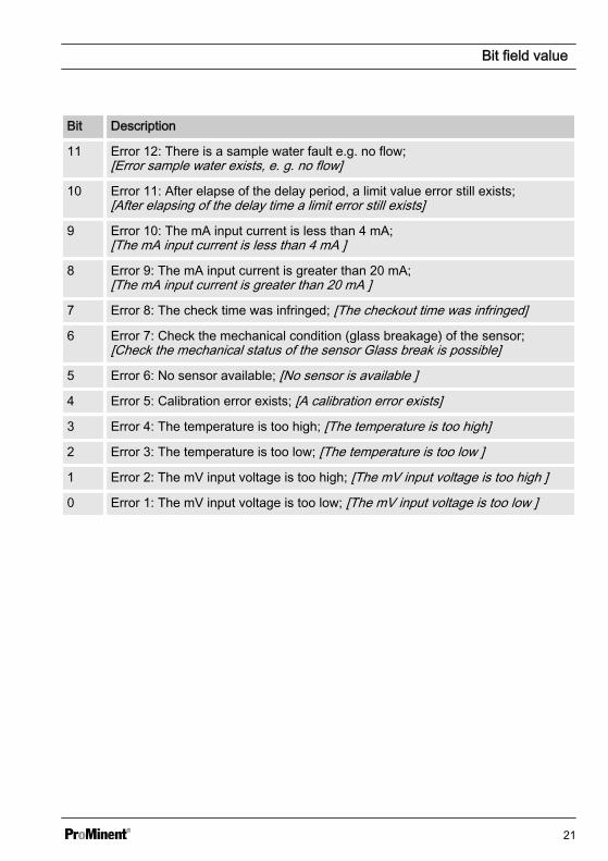
2.2 Error of the channel
Bit Description
31 Error 99: There is a system error;[A system error exists]
30
29
28
27
26
25
24
23
22
21
20 Error 88: The connection to the extension module is faulty;[The connection to the expansion module is faulty ]
19 Error 34: Incorrect correction variable; [Incorrect correction variable ]
18 Error 19: The liquid level in storage tank 3 is too low;[The level in tank 3 is too low ]
17 Error 18: The liquid level in storage tank 2 is too low;[The level in tank 2 is too low ]
16 Error 17: The liquid level in storage tank 1 is too low;[The level in tank 1 is too low ]
15 Error 16: The mA input is overloaded; [The mA input is overloaded]
14 Error 15: The mA input supply is overloaded;[The mA input supply is overloaded]
13 Error 14: The status of the controller is pause / hold [PAUSE / HOLD];[The controller is in the state PAUSE / HOLD]
12 Error 13: The status of the controller is pause [PAUSE];[The controller is in the state PAUSE]
Bit field value
20
Bit Description
11 Error 12: There is a sample water fault e.g. no flow;[Error sample water exists, e. g. no flow]
10 Error 11: After elapse of the delay period, a limit value error still exists;[After elapsing of the delay time a limit error still exists]
9 Error 10: The mA input current is less than 4 mA;[The mA input current is less than 4 mA ]
8 Error 9: The mA input current is greater than 20 mA;[The mA input current is greater than 20 mA ]
7 Error 8: The check time was infringed; [The checkout time was infringed]
6 Error 7: Check the mechanical condition (glass breakage) of the sensor;[Check the mechanical status of the sensor Glass break is possible]
5 Error 6: No sensor available; [No sensor is available ]
4 Error 5: Calibration error exists; [A calibration error exists]
3 Error 4: The temperature is too high; [The temperature is too high]
2 Error 3: The temperature is too low; [The temperature is too low ]
1 Error 2: The mV input voltage is too high; [The mV input voltage is too high ]
0 Error 1: The mV input voltage is too low; [The mV input voltage is too low ]
Bit field value
21

2.3 Warning of the channel
Bit Description
15
14
13
12
11
10
9
8
7
6 Warning 73: The fan has a fault; [The fan has an error]
5 Warning 72 The time must be checked; [The time must be checked]
4 Warning 71 The battery needs to be replaced; [The battery must be replace]
3 Warning 4 The measuring channel is not yet calibrated;[The measuring channel is not yet calibrated]
2 Warning 3 The wash timer has timed out. Maintenance is required;[The wash timer has timed out. Maintenance is necessary]
1 Warning 2 The limit value was exceeded; [The limit was exceeded ]
0 Warning 1 The limit value was not reached; [The limit was undershot]
Bit field value
22

2.4 Potential-free relayIf relay output is active, then according bit is used.
Bit Description
15
14
13
12
11
10
9
8
7
6
5
4
3
2 Configuring alarm relay (XR3)
1 Relay 2 (XR2)
0 Relay 1 (XR1)
Bit field value
23

2.5 Settings of the channel configuration
Bit Description
15 1 = channel uses remote control parameters; 0 = channel uses internal parame‐ters;[1 = Channel uses remote control parameters; 0 = Channel uses internalparameters]
14 1 = channel uses internal set 2; 0 = channel uses internal set 1;[1 = Use internal parameter set 2; 0 = Use internal parameter set 1]
13
12
11
10
9
8
7
6 0 = control off; 1 = manual; 2 = P (1 direction, lift);[0 = Control off; 1 = manual; 2 = P (1 way, increase) ]
5 3 = P (1 direction, lower); 4 = P (2 direction, standard); 5 = P (2 direction, deadband);[3 = P (1 way, decrease); 4 = P (2 way, standard); 5 = P (2 way, deadzone)]
4 6 = PID (1 direction, lower); 7 = P (1 direction, lower); 8 = PID (2 direction,standard);[6 = PID (1 way, increase) 7 = P (1 way, decrease) 8 = PID (2way, standard)]
3 9 = PID (2 direction, dead band); [9 = PID (2 way, deadzone)]
2
1 1 = limit value 2 configuration high; 0 = limit value 2 configuration low;[1 = Limit 2 Configuration high; 0 = Limit 2 Configuration low]
0 1 = limit value 1 configuration high; 0 = limit value 1 configuration low;[1 = Limit 1 Configuration high; 0 = Limit 1 Configuration low ]
n Bit 14 is only valid if bit 15 = 0n Bit 3, 4, 5, 6 are only valid if bit 15 = 1n Bit 3, 4, 5, 6, 14, 15 only exists on channels 1 and 2
Bit field value
24

2.6 CRC-16 calculationextern void calculate_CRC(unsigned char *message, int length,unsigned char *CRC)unsigned char CRCHi, CRCLo, TempHi, TempLo;static const unsigned char table[512] = {
0x00, 0x00, 0xC0, 0xC1, 0xC1, 0x81, 0x01, 0x40, 0xC3, 0x01,0x03, 0xC0, 0x02, 0x80, 0xC2, 0x41,0xC6, 0x01, 0x06, 0xC0, 0x07, 0x80, 0xC7, 0x41, 0x05, 0x00,0xC5, 0xC1, 0xC4, 0x81, 0x04, 0x40,0xCC, 0x01, 0x0C, 0xC0, 0x0D, 0x80, 0xCD, 0x41, 0x0F, 0x00,0xCF, 0xC1, 0xCE, 0x81, 0x0E, 0x40,0x0A, 0x00, 0xCA, 0xC1, 0xCB, 0x81, 0x0B, 0x40, 0xC9, 0x01,0x09, 0xC0, 0x08, 0x80, 0xC8, 0x41,0xD8, 0x01, 0x18, 0xC0, 0x19, 0x80, 0xD9, 0x41, 0x1B, 0x00,0xDB, 0xC1, 0xDA, 0x81, 0x1A, 0x40,0x1E, 0x00, 0xDE, 0xC1, 0xDF, 0x81, 0x1F, 0x40, 0xDD, 0x01,0x1D, 0xC0, 0x1C, 0x80, 0xDC, 0x41,0x14, 0x00, 0xD4, 0xC1, 0xD5, 0x81, 0x15, 0x40, 0xD7, 0x01,0x17, 0xC0, 0x16, 0x80, 0xD6, 0x41,0xD2, 0x01, 0x12, 0xC0, 0x13, 0x80, 0xD3, 0x41, 0x11, 0x00,0xD1, 0xC1, 0xD0, 0x81, 0x10, 0x40,0xF0, 0x01, 0x30, 0xC0, 0x31, 0x80, 0xF1, 0x41, 0x33, 0x00,0xF3, 0xC1, 0xF2, 0x81, 0x32, 0x40,0x36, 0x00, 0xF6, 0xC1, 0xF7, 0x81, 0x37, 0x40, 0xF5, 0x01,0x35, 0xC0, 0x34, 0x80, 0xF4, 0x41,0x3C, 0x00, 0xFC, 0xC1, 0xFD, 0x81, 0x3D, 0x40, 0xFF, 0x01,0x3F, 0xC0, 0x3E, 0x80, 0xFE, 0x41,0xFA, 0x01, 0x3A, 0xC0, 0x3B, 0x80, 0xFB, 0x41, 0x39, 0x00,0xF9, 0xC1, 0xF8, 0x81, 0x38, 0x40,0x28, 0x00, 0xE8, 0xC1, 0xE9, 0x81, 0x29, 0x40, 0xEB, 0x01,0x2B, 0xC0, 0x2A, 0x80, 0xEA, 0x41,
Bit field value
25

0xEE, 0x01, 0x2E, 0xC0, 0x2F, 0x80, 0xEF, 0x41, 0x2D, 0x00,0xED, 0xC1, 0xEC, 0x81, 0x2C, 0x40,0xE4, 0x01, 0x24, 0xC0, 0x25, 0x80, 0xE5, 0x41, 0x27, 0x00,0xE7, 0xC1, 0xE6, 0x81, 0x26, 0x40,0x22, 0x00, 0xE2, 0xC1, 0xE3, 0x81, 0x23, 0x40, 0xE1, 0x01,0x21, 0xC0, 0x20, 0x80, 0xE0, 0x41,0xA0, 0x01, 0x60, 0xC0, 0x61, 0x80, 0xA1, 0x41, 0x63, 0x00,0xA3, 0xC1, 0xA2, 0x81, 0x62, 0x40,0x66, 0x00, 0xA6, 0xC1, 0xA7, 0x81, 0x67, 0x40, 0xA5, 0x01,0x65, 0xC0, 0x64, 0x80, 0xA4, 0x41,0x6C, 0x00, 0xAC, 0xC1, 0xAD, 0x81, 0x6D, 0x40, 0xAF, 0x01,0x6F, 0xC0, 0x6E, 0x80, 0xAE, 0x41,0xAA, 0x01, 0x6A, 0xC0, 0x6B, 0x80, 0xAB, 0x41, 0x69, 0x00,0xA9, 0xC1, 0xA8, 0x81, 0x68, 0x40,0x78, 0x00, 0xB8, 0xC1, 0xB9, 0x81, 0x79, 0x40, 0xBB, 0x01,0x7B, 0xC0, 0x7A, 0x80, 0xBA, 0x41,0xBE, 0x01, 0x7E, 0xC0, 0x7F, 0x80, 0xBF, 0x41, 0x7D, 0x00,0xBD, 0xC1, 0xBC, 0x81, 0x7C, 0x40,0xB4, 0x01, 0x74, 0xC0, 0x75, 0x80, 0xB5, 0x41, 0x77, 0x00,0xB7, 0xC1, 0xB6, 0x81, 0x76, 0x40,0x72, 0x00, 0xB2, 0xC1, 0xB3, 0x81, 0x73, 0x40, 0xB1, 0x01,0x71, 0xC0, 0x70, 0x80, 0xB0, 0x41,0x50, 0x00, 0x90, 0xC1, 0x91, 0x81, 0x51, 0x40, 0x93, 0x01,0x53, 0xC0, 0x52, 0x80, 0x92, 0x41,0x96, 0x01, 0x56, 0xC0, 0x57, 0x80, 0x97, 0x41, 0x55, 0x00,0x95, 0xC1, 0x94, 0x81, 0x54, 0x40,0x9C, 0x01, 0x5C, 0xC0, 0x5D, 0x80, 0x9D, 0x41, 0x5F, 0x00,0x9F, 0xC1, 0x9E, 0x81, 0x5E, 0x40,0x5A, 0x00, 0x9A, 0xC1, 0x9B, 0x81, 0x5B, 0x40, 0x99, 0x01,0x59, 0xC0, 0x58, 0x80, 0x98, 0x41,0x88, 0x01, 0x48, 0xC0, 0x49, 0x80, 0x89, 0x41, 0x4B, 0x00,0x8B, 0xC1, 0x8A, 0x81, 0x4A, 0x40,0x4E, 0x00, 0x8E, 0xC1, 0x8F, 0x81, 0x4F, 0x40, 0x8D, 0x01,0x4D, 0xC0, 0x4C, 0x80, 0x8C, 0x41,
Bit field value
26

0x44, 0x00, 0x84, 0xC1, 0x85, 0x81, 0x45, 0x40, 0x87, 0x01,0x47, 0xC0, 0x46, 0x80, 0x86, 0x41,0x82, 0x01, 0x42, 0xC0, 0x43, 0x80, 0x83, 0x41, 0x41, 0x00,0x81, 0xC1, 0x80, 0x81, 0x40, 0x40,
CRCHi = 0xff;CRCLo = 0xff;while(length){TempHi = CRCHi;TempLo = CRCLo;CRCHi = table[2 * (*message ^ TempLo)];CRCLo = TempHi ^ table[(2 * (*message ^ TempLo)) + 1];message++;length--; };CRC [0] = CRCLo;CRC [1] = CRCHi;return;}
Bit field value
27

984163, 2, en_GB
© 2015
ProMinent GmbHIm Schuhmachergewann 5 - 1169123 HeidelbergTelephone: +49 (6221) 842-0Fax: +49 (6221) 842-419Email: [email protected]: www.prominent.com