Embed Size (px)
Citation preview

Duke Energy SeminarSeptember 3 – 5, 2008Concord, NC

1 /GE /
Particulate CollectionExternal Factors
Duke / WPCA SeminarBob TaylorSeptember 2008

2 /GE /
PM Collection – External Factors
• A large part of our daily lives is spent maintaining PM emission limits.
• When emissions approach compliance limits, we get a call to correct the problem.
• Our first action is generally to review operation of the electrostatic precipitator or fabric filter.
• Aside from maintenance issues, it is likely that the source of the problem is not the PM control device, but process conditions.
• For this reason, it is critical to consider the whole system when addressing emissions issues.

3 /GE /
You have a PM control eventDefine the nature of the event to focus your efforts:• Characterize emission levels
– Rapid spikes– Gradual increase
• Characterize PM event– Random in nature– Cyclical based on time or process condition
• ESP - review electrical conditions– Small number of fields affected– Consistent impact throughout all fields
• Fabric filter - review broken bag detector data– High emissions isolated to a single compartment– Multiple compartments experiencing increased
emissions

4 /GE /
Where should you look first?
• Inlet Dust Load• Flue Gas Flow Rate• Flue Gas Temperature• Flue Gas Composition• Particle Size Distribution• Carbon Content of Ash
(This assumes it really isn’t thePM control devices fault!)
Major factors affecting PM removal;

5 /GE /
PM Collection – External Factors• Most of the fly ash is a constituent of the fuel
burned.• As a result, dust loading is proportional to firing
rate and ash content of fuel.• Why does inlet dust burden change?
• Change in load• Change in fuel ash constant• Increased unburned carbon in ash• Injection of sorbent ahead of PM device• Short term activities such as soot blowing

6 /GE /
Consider an example 250 MW coal fired boiler burning a Powder River Basin coal:•Coal burn rate: 306,000 lb/hr•Heating value: 7,850 BTU/lb•Ash content: 6.5%•Gas volume: 1,088,000 ACFM•Gas temperature: 325°F•Gas pressure: -6” WC•Dust burden: 6.6 lb/mmBTU
2.87 gr/dscf
Impact of Combustion on Particulate Collection

7 /GE /
~CoalSupply
CoalCrusher
Mill
CoalSilos Boiler
AirHeater
Stack
IDFan
FDFan Turbine Generator
About 15% to 20% of Ash Falls out as Bottom AshAbout 80% to 85% Passes Through Boiler as Fly AshFor a 250 MW Plant – 9.5 to 10.0 Tons/hr ash
7.5 to 8 Tons/hr fly ash
PM Collection – External FactorsIn a typical pulverized coal fired boiler;

8 /GE /
PM Collection – External FactorsExample 250 MW PlantCoal HHV - 7,850 BTU/lb (from Ultimate Analysis)Heat input – 2,400 mmBTU/hr (Boiler rating)Fuel burn rate = (2,400 mmBTU/hr) / (7,850 BTU/lb /1,000,000)
= 306,000 lb coal /hr or 153 tons coal /hrCoal Ash Content 6.5%
Ash= 306,000 lb coal /hr * .065 lb ash/lb coal=19,890 lb ash/hr or 9.95 tons ash/hrAt 80% conversion of ash to fly ash=19,890 lb ash/hr * 0.8=16,000 lb fly ash/hr or 8 tons fly ash/hr @ 6.5%
ash=24,615 lb fly ash/hr or 12.3 ton fly ash/hr @ 10%
ash

9 /GE /
What happens when dust load increases?Electrostatic Precipitator• Increased emissions• Increased spark rate•Constant pressure drop•Need for increased rapping
•Potential for increased erosion.
•Reduced hopper evacuation cycles.
Fabric Filter•Constant emissions• Increased pressure drop•Need to reduce pulse cleaning interval
• Increased bag wear.• Increased compressed air consumption.
•Reduced hopper evacuation cycles.

10 /GE /
What can I do when dust loading increases?Electrostatic Precipitator• Increase hopper evacuation rate.
•Reduce inlet field collecting late rapping interval, increase force.
•Monitor second field to quantify impact of first field changes.
• If using flue gas conditioning, increase SO3 injection rate.
Fabric Filter• Increase hopper evacuation rate.
• If using POD, monitor upper pressure set point limit versus pulsing interval.
• If using timer pulsing, decrease interval between pulses.
•Monitor sample bags for signs of wear.

11 /GE /
PM Collection – External FactorsFlue gas Flow Rate• Flue gas is a combination of
combustion products and air in-leakage.
• Combustion products are a function of the fuel constituents and the excess air utilized during burning.
• Perfect combustion would require a stoichiometry of “1”, as defined by fuel composition (Ultimate Analysis)
• Real world, excess is air required since fuel/air mixing less than perfect
• Air in-leakage accounts for significant increase in volume

12 /GE /
Why does gas volume change?Factors affecting flue gas volume:
– Fuel burn rate– Fuel characteristics– Integrity of the casing and duct work– Moisture content of the gas]– Temperature of the gas
PM Collection – External Factors

13 /GE /
Impact of air in-leakage on Gas Volume• In a negative pressure PM control device,
ambient air will leak into the flue gas.• Consider gas volume at two O2 levels:
• 4.5% O2 ~1,088,000 ACFM• 6.5% O2 ~1,250,000 ACFM
• Significant increase in flue gas flow results from in-leakage.
• What impact does that have on PM equipment?
14 /GE /
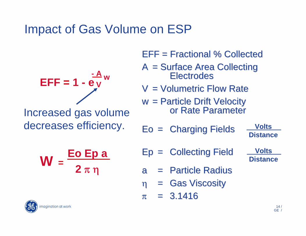
EFF = Fractional % CollectedEFF = Fractional % CollectedAA = Surface Area Collecting = Surface Area Collecting
ElectrodesElectrodesVV = Volumetric Flow Rate= Volumetric Flow Rateww = Particle Drift Velocity = Particle Drift Velocity
or Rate Parameteror Rate Parameter
EoEo == Charging Fields Charging Fields
EpEp == Collecting FieldCollecting Field
aa == Particle RadiusParticle Radiusηη == Gas Viscosity Gas Viscosity ππ == 3.14163.1416
VoltsDistance
EFF = 1 - e- A
Vw
Eo Ep a2 π η
W =Volts
Distance
Impact of Gas Volume on ESP
Increased gas volume decreases efficiency.

15 /GE /
Impact of Gas Volume on Fabric FilterAir to Cloth Ratio
• Air to cloth ratio = Total gas volume ACFM / Total filter area Ft2
• Filter dia. X length x 3.1415 = Filter area
• Total # Filters x Filter Area = Total Filter Area
• Typical pulse jet air to cloth ratios for utility boilers 2.0 through 4.0 ft/min.
Air to Cloth Ratio• Air to cloth ratio = Total gas volume ACFM / Total filter area Ft2
• Filter dia. X length x 3.1415 = Filter area
• Total # Filters x Filter Area = Total Filter Area
• Typical pulse jet air to cloth ratios for utility boilers 2.0 through 4.0 ft/min.
•Collection efficiency is not volume dependent.
• Increased gas volume results in increased ΔP

16 /GE /
Can Velocity
In a pulse jet fabric filter, “can”velocity is the upward gas velocity between filter bags.
It is calculated at the horizontal cross section at the bottom of the filter bags.
Excessive can velocity prevents dust from settling into hoppers.
Increased gas volume results in increased can velocity.
Impact of Gas Volume on Fabric Filter

17 /GE /
Impact of air in-leakage on Gas VolumeAt 2.87 gr/dscf inlet dust, the • Impact on ESP
• 4.5% O2 ~1,088,000 ACFM– 99.4% removal efficiency– 0.017 gr/dscf
• 6.5% O2 ~1,250,000 ACFM– 98.84% removal efficiency– 0.033 gr/dscf
• Impact on Fabric Filter• 4.5% O2 ~1,088,000 ACFM
– 3.5 ft/min Air to cloth ratio– 205 ft/min
• 6.5% O2 ~1,250,000 ACFM– 4.05 ft/min Air to cloth ratio– 235 ft/min
ESP emissions almost double
FF pressure drop ~30% increase

18 /GE /
Impact of Increased Gas Volume
Electrostatic Precipitator•Reduced collection efficiency
• Increased pressure drop• Increased emissions• Increased abrasion • Instability in high voltage system
Fabric Filter•Relatively constant emissions
• Increased pressure drop•Reduction in cleaning cycle interval
•Reduced bag life• Inability of dust to settle•Abrasion from swinging bags

19 /GE /
What should you do when gas volume increases?
Electrostatic Precipitator• Look for open access points; doors, test ports, poke holes.
• Identify and repair chronic sources of in-leakage.
• Compare inlet gas temperature to normal conditions.
• Minimize outlet field rapping. • Keep hoppers evacuated.• Look for increased spark rate due to oscillation.
Fabric Filter• Reduce interval between cleaning cycles, increase upper pressure set point.
• Identify and repair sources of in-leakage.
• Compare inlet gas temperature to normal conditions.
• Bring all compartments on-line.
• Obtain sample bags and inspect.

20 /GE /
Impact of Gas TemperatureChanges in PM device inlet temperature affects its’ operation. Temperature change may result from:•Slagging or fouling in furnace•Change in OFA configuration•Excessive ambient air in-leakage•Use of air pre-heater in winter•Load change•Change in coal grind•Loss of humidification
~CoalSupply
CoalCrusher
Mill
CoalSilos
Boiler
AirHeater
Stack
IDFan
FDFan
Turbine Generator
Economizer Outlet Temperature~700 to 800 °F
Air Heater Outlet Temperature~275 to 350 °F
High or Low Temperature is a problem
21 /GE /
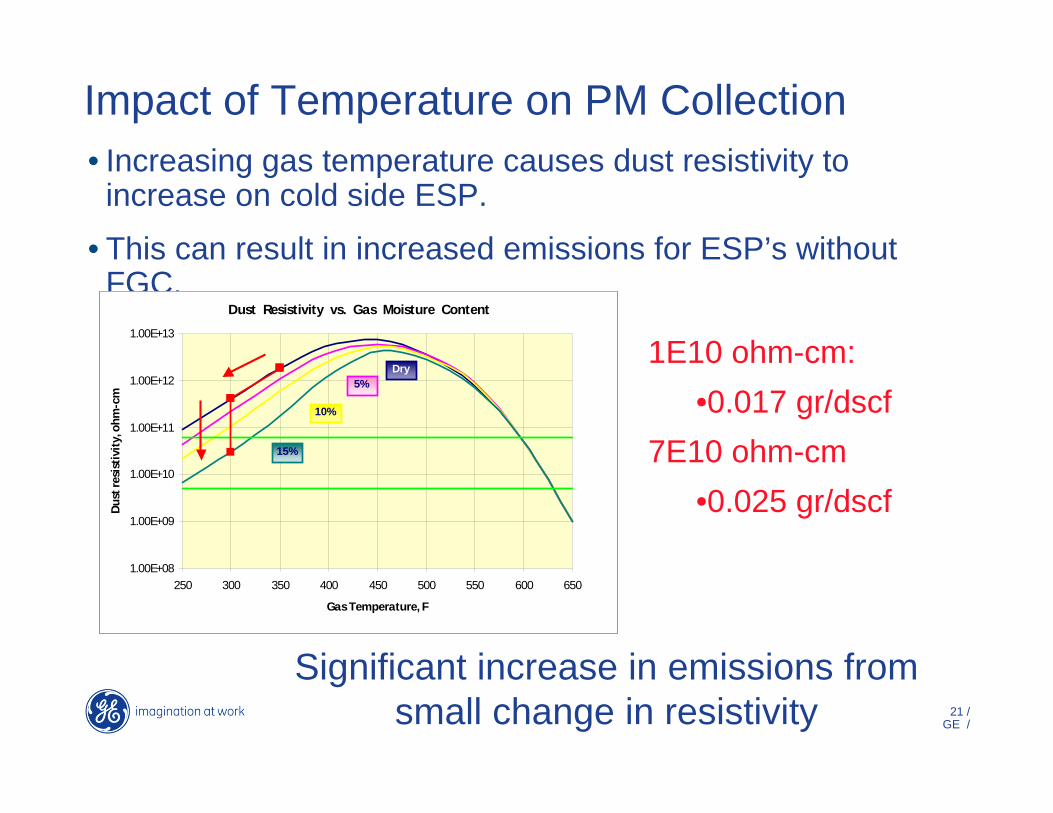
• Increasing gas temperature causes dust resistivity to increase on cold side ESP.
• This can result in increased emissions for ESP’s without FGC.
Impact of Temperature on PM Collection
Dust Resistivity vs. Gas Moisture Content
1.00E+08
1.00E+09
1.00E+10
1.00E+11
1.00E+12
1.00E+13
250 300 350 400 450 500 550 600 650
Gas Temperature, F
Dust
resi
stiv
ity, o
hm-c
m
Dry5%
10%
15%
Dust Resistivity vs. Gas Moisture Content
1.00E+08
1.00E+09
1.00E+10
1.00E+11
1.00E+12
1.00E+13
250 300 350 400 450 500 550 600 650
Gas Temperature, F
Dust
resi
stiv
ity, o
hm-c
m
Dry5%
10%
15%
1E10 ohm-cm: •0.017 gr/dscf
7E10 ohm-cm•0.025 gr/dscf
Significant increase in emissions from small change in resistivity

22 /GE /
Impact of Temperature on PM Collection
Electrostatic Precipitator• Increased gas volume• Possible dust resistivity increase
• Increased emissions• Damage to insulators• Damage to elastomer seals• Reduced sorbent effectiveness
• Possible increase in corrosion.
Fabric Filter• Increased gas volume• Reduced fabric life• Loss of filter bags• Damage to elastomer seals
• Reduced sorbent effectiveness
• Possible increase in corrosion.

23 /GE /
What can I do?Electrostatic Precipitator• Monitor secondary current and spark trends.
• If high resistivity;• Implement intermittent
energization• Aggressive collecting
plate rapping• Reduced power rapping
• Blow soot (Steam)• If temperature too low, reduce in-leakage.
• Consider adding moisture
Fabric Filter• Monitor temperature relative to media limits.
• If temperature too high, bleed in ambient air or introduce EGC.
• If temperature too low, reduce in-leakage or reduce water injection rate.

24 /GE /
Impact of Fuel Composition•As shown previously, composition of the coal affects dust burden and gas volume.
• In addition, gas composition can affect other factors: • Sulfur & iron oxide affect acid
dew point• Moisture affects volume and
acid dew point• Incomplete combustion
increases carbon monoxide and carbon content of ash.

25 /GE /
Bag House Basics Filter Media Selection
500°F(259°C)
Fair
Excellent
Good
Fair
Good
Excellent
XXXXXXX
Oper. Vari. Polyester Acrylic Fiberglass Aramid PPS P84
Max. Oper. Temperature
Abrasion
Filtration Properties
Moist Heat
Alkalines
Mineral Acids
Oxygen(15%+)
Relative Cost
275°F(134°C)
Excellent
Excellent
Poor
Fair
Fair
Excellent
X
265°F(130°C)
Good
Good
Excellent
Fair
Good
Excellent
XX
500°F(259°C)
Fair
Fair
Excellent
Fair
Poor**
Excellent
XXX
400°F(204°C)
Excellent
Excellent
Good
Good
Fair
Excellent
XXXX
375°F(190°C)
Good
VeryGood
Excellent
Excellent
Excellent
Poor
XXXXXX

26 /GE /
Impact of Coal CompositionElectrostatic Precipitator
• Increased moisture can benefit dust resistivity.
• Increased acids can benefit dust resistivity
•Excessive moisture or acids can degrade rapping and increase corrosion
•Elevated CO possible explosion
Fabric Filter• Increased moisture can lead to bag blinding
• Increased acids can degrade fabrics
•Excessive oxygen can degrade some fabrics
•Excessive moisture can degrade some fabrics.
•Elevated CO possible explosion

27 /GE /
Response to Coal CompositionElectrostatic Precipitator•Monitor dew point of gas stream and adjust inlet temperature.
•Adjust rapping intensity and frequency when dust resistivity changes.
•Modify flue gas conditioning system injection rates based on secondary current and spark rates.
Fabric Filter• Increase pulse frequency when moisture make dust sticky.
•Monitor change in acids relative to media capabilities.
• Improve coal grind to lower excess air.
• Inject alkali ahead of FF to react with acids.

28 /GE /
Particle Size Distribution
~CoalSupply
CoalCrusher
Mill
CoalSilos Boiler
AirHeater
Stack
IDFan
FDFan Turbine Generator
Crusher ~ 1” “particles”
Mills - 70% through 200 mesh screen – 125 microns
Fly ash particle size is a function of coal grind and coal characteristics (volatile content influences)
Typical pulverized coal grind characteristics
29 /GE /
Particle Size Distribution
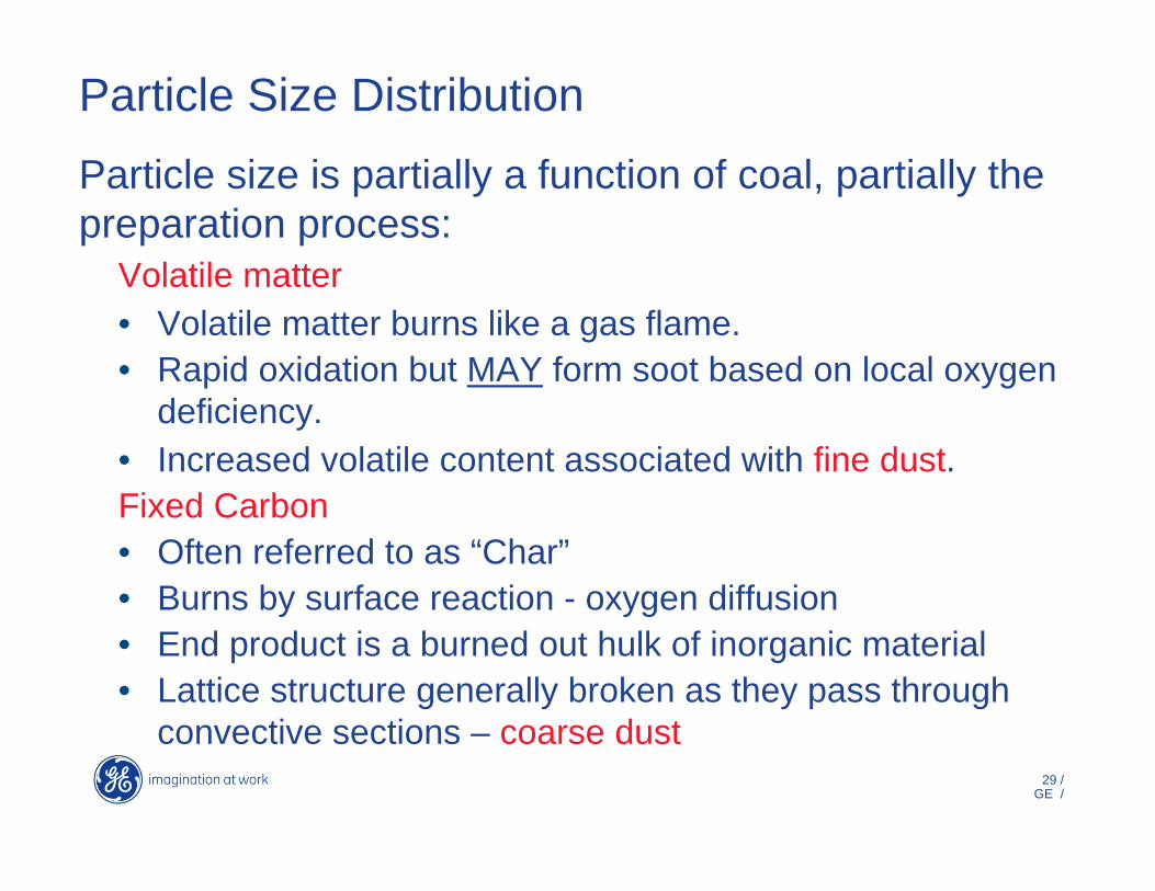
Particle size is partially a function of coal, partially the preparation process:
Volatile matter• Volatile matter burns like a gas flame.• Rapid oxidation but MAY form soot based on local oxygen
deficiency.• Increased volatile content associated with fine dust.Fixed Carbon• Often referred to as “Char”• Burns by surface reaction - oxygen diffusion• End product is a burned out hulk of inorganic material• Lattice structure generally broken as they pass through
convective sections – coarse dust

30 /GE /
Impact of Particle Size Distribution
Radiant Energy
Volatile Matter Vaporizes and Erupts
From ParticleCoal Particle
100 μ
Particle Heat Rate~ 10,000 °K/sec
Blow Hole
Typical coal combustion of volatile matter

31 /GE /
EFF = Fractional % CollectedEFF = Fractional % CollectedAA = Surface Area Collecting = Surface Area Collecting
ElectrodesElectrodesVV = Volumetric Flow Rate= Volumetric Flow Rateww = Particle Drift Velocity = Particle Drift Velocity
or Rate Parameteror Rate Parameter
EoEo == Charging Fields Charging Fields
EpEp == Collecting FieldCollecting Field
aa == Particle RadiusParticle Radiusηη == Gas Viscosity Gas Viscosity ππ == 3.14163.1416
VoltsDistance
EFF = 1 - e- A
Vw
Eo Ep a2 π η
W =Volts
Distance
Impact of Particle Size on ESP
Reduced particle size decreases efficiency.

32 /GE /
Impact of Reduced Particle Size
Electrostatic Precipitator•Reduced collection efficiency
•Excessive space charge conditions; current suppression
• Increased potential for re-entrainment.
•Elevated impact on opacity
Fabric Filter•Potential bag blinding•Fabric “bleed Thru”•Possible increased emissions
• Increased pressure drop due to lack of settling
•Elevated impact on opacity

33 /GE /
What can I do? Electrostatic Precipitator• Improve gas flow uniformity to eliminate channeling.
• Monitor spark rates and space charge, HV stability.
• Eliminate sneakage or sweepage.
• Increase rapper off times to maximize agglomeration.
• Consider agglomeration
Fabric Filter• Pre-coat filter bags.• Change to felt from woven.• Consider membrane laminated filter media.
• Decrease pulse pressure and cycles.
• Improve internal gas distribution.
• Consider agglomeration

34 /GE /
Carbon in Fly Ash
Factors Affecting Complete Burn Out• Residence time from burners to nose• Effectiveness of fuel/air mixing• Reactivity of char• Coal grind• Introduction of over fire air
~CoalSupply
CoalCrusher
Mill
CoalSilos Boiler
AirHeater
Stack
IDFan
FDFan Turbine Generator
Incomplete burn out results in increased unburned carbon in fly ash.

35 /GE /
Carbon in Fly Ash
Other Sources of Carbon in Fly Ash
• Incomplete combustion is not the only reason for carbon in ash.
•Mercury control strategies utilizing carbon based sorbents are another reason.
•Powdered activated carbon is injected into the gas stream ahead of the PM control device.
•This process increases the dust burden to the PM control device.

36 /GE /
Impact of PAC Injection on Dust Burden
• Injecting PAC ahead of ESP has minimal impact on FF inlet dust burden.
• Injecting after ESP has major impact on FF dust burden. (Polishing mode)
PAC Rate lb/mmBTU
Inlet Dust gr/acf
PAC Injection gr/acf
Total Burden gr/acf
% Increase
1.5 1.5 0.011 1.511 0.733 1.5 0.022 1.522 1.507 1.5 0.049 1.55 3.33
PAC Rate lb/mmBTU
Inlet Dust gr/acf
PAC Injection gr/acf
Total Burden gr/acf
% Increase
1.5 0.015 0.011 0.026 173.003 0.015 0.022 0.037 247.007 0.015 0.049 0.064 427.00
Total Dust Burden
Polishing Mode

37 /GE /
Carbon Content of Ash•An ESP is not as effective at removing carbon as compared to fly ash.
•Field testing indicates ESP emissions may increase when PAC is utilized.
•Performance is a function of the number of electrical fields, gas velocity, and general condition of ESP.
•Carbon has lower reflectance when compared to fly ash. (Visible emissions)
•Field testing indicates PAC can create potential for hopper fires.

38 /GE /
Impact of Carbon in Fly AshElectrostatic Precipitator• Increased spark rate• Increased re-entrainment• Potential for insulator tracking
• Potential for hopper fires• Inability to sell fly ash• Decreased effectiveness of activated carbon
• Potential increased dust resistivity.
Fabric Filter• Hydrocarbons can blind filter bags
• Potential for hopper fires• Inability to sell fly ash• Decreased effectiveness of activated carbon

39 /GE /
What can I do?Electrostatic Precipitator• Maintain elevated secondary
current densities.• Minimize outlet field rapping.• Eliminate hopper in-leakage.• Monitor operation of hopper heating
equipment. • Eliminate internal stabilizer
insulators. • Pressurize support insulators.• Consider agglomeration.• Evacuate hoppers frequently.• Verify proper coal grind. • Balance primary and over fire air.
Fabric Filter• Pre-coat new filter bags to avoid
blinding.• Consider membrane laminated
filter media.• Establish “sacrificial” start-up
compartment. • Empty hoppers frequently. • Minimize hopper in-leakage.• Monitor operation of hopper
heating equipment. • Verify proper coal grind.• Balance primary and over fire air.

40 /GE /
Summary• The PM control device may not be the source of emission
problems.• Multiple external factors impact operation of the PM control
device.• The PM device has no direct influence over these
parameters. • Understanding conditions associated with “Normal” operation
helps when trouble shooting. • Define process parameters that have most impact on
equipment operation and establish trending. • Understand the result of changes in any of the critical
parameters. • Do not focus on any single area, the problem is likely a
combination of issues.


![dpv-uk.com · PDF fileEndure of Thermal shock. ... Ash Silo wz Pneumatic Ash Handling System Layout Chimney Pressue Pump Ash Silo czX-Ð] cz ESP Ash Silo ESP Ash](https://img.dokumen.tips/doc/110x75/5abd4e267f8b9a7e418b6dff/dpv-ukcom-of-thermal-shock-ash-silo-wz-pneumatic-ash-handling-system-layout.jpg)