Embed Size (px)
Citation preview

Pipelines 2016 280
© ASCE 1
Ductile Iron Piping Systems Ductile Iron Piping Systems Ductile Iron Piping Systems Ductile Iron Piping Systems UsedUsedUsedUsed on the Design and Construction on the Design and Construction on the Design and Construction on the Design and Construction
of the Third Set of Locks Projectof the Third Set of Locks Projectof the Third Set of Locks Projectof the Third Set of Locks Project
Jeffrey E. Erwin, P.E.1; Remigijus Aruna, P.E.2; Gabriel E. Restrepo, P.E., M. ASCE3
1 MWH Global, 350 N. Orleans Street, Chicago, IL 60654, Email: [email protected] 2 MWH Global, 350 N. Orleans Street, Chicago, IL 60654, Email: [email protected] 3 American Cast Iron Pipe Company, 1501 31st Avenue North, Birmingham, AL 35207 Email: [email protected]
Abstract
The Panama Canal Expansion is a $5.25-billion project sponsored by the Panama Canal Authority, which includes the $3.2 billion for the Design and Construction of the Third Set of Locks. Buried beneath the new lock’s footprint are 80,000 feet of ductile iron pipe, providing potable water, dewatering and fire protection service to the new locks’ facilities and the surrounding communities.
This paper will discuss the pipe design, selection, design/build challenges encountered during the process and how it affected the pipe manufacturing and scheduling. It will demonstrate how the use of 3D modeling software was used to coordinate the ductile iron pipe with other buried utilities. It will present a unique installation of 30-inch and 24-inch potable water flanged ductile iron pipe crossing underneath the lock structure that required a 450 psi hydrostatic test on the 30-inch pipeline after installation. Due to the unique high performance requirement, which reached beyond normal testing criteria for water piping, special design and testing for the joint system was developed for this project.
The paper will also describe how teamwork and cooperation among the designer, the contractor and the equipment manufacturer/supplier were essential for the successful construction and operation of the ductile iron piping component of the overall megaproject.
PROJECT HISTORY
The Panama Canal Expansion - Third Set of Locks Project will add a third lane to the existing Panama Canal locks to allow Post-Panamax size ships to traverse the Canal, greatly expanding shipping through the isthmus. The Third Set of Locks Project consists of a new lock complex at both the Atlantic and Pacific entrances to the Canal, which will allow vessels to move between Lake Gatun and sea level, an elevation difference of about 89 feet. Both the Atlantic and the Pacific locks’ complexes contain three lock chambers, which are 180 feet wide and 1,476 feet long, and separated by lock heads with rolling gates. See Figure 1 below for an overall plan view of the Pacific locks complex. Once completed, the locks will allow for the passage of the super container vessels, affecting trade and commerce throughout the world. For more

Pipelines 2016 280
© ASCE 2
information regarding the Third Set of Locks project visit the Panama Canal Authority (ACP) website: www.pancanal.com/eng/
Figure 1: Overall Plan of the Pacific Locks Complex
BACKGROUND
ACP awarded the Third Set of Locks Project to the Spanish/Italian/Belgian construction joint venture Grupo Unidos Por el Canal (GUPC) as a design-build contract. GUPC selected the MWH-led design joint-venture CICP Consultores Internacionales (CICP) to prepare the tender design that resulted in the highest ranking technical proposal. CICP then completed the final design and engineering services during construction (ESDC) and quality assurance (QA) for the project. AMERICAN Ductile Iron Pipe was the selected manufacturer of the pipe, fittings, valves and accessories for the ductile iron piping systems.
Among the numerous electro-mechanical systems and equipment related to the project, there were four main systems that include ductile iron pipe as described below.
A foam/water fire protection system comprised of two separate ductile iron piping transmission systems (foam and water) was designed to discharge an aqueous film forming foam solution in the event of a flammable liquid spill at the lock complex lake and ocean entrances. The piping system interconnected pumps with hydrants, remote controlled monitors, and aspirating nozzles through the use of ductile iron pipe with sizes ranging from 3 inches to 20 inches with an operating pressure up to 180 psi. Each of the eight remotely controlled monitors has a foam/water discharge rate of 4,000 gallons per minute and a range of 220 feet.
A dewatering system was designed with the capability to dewater a range of locations around the project site for maintenance operations including a dewatering lift station with eight 300-horsepower dewatering pumps with the capacity to dewater the entire lock complex (approximate volume of 250 million gallons) in 48 hours. Pipe sizes for the system range from 8 inches to 16 inches and an operating system up to 60 psi.
A potable water relocation system comprised of three separate ductile iron piping systems was designed to provide uninterrupted continuous service for all
BORINQUEN DAMS

Pipelines 2016 280
© ASCE 3
existing water mains. This included a section of pipe that was installed through a utility gallery under the locks (the Crossunder structure), approximately 130 feet below grade and 430 feet long. The uniqueness of this installation will be described in more detail below. Pipe sizes for the potable water relocation systems were 16 inches, 24 inches, and 30 inches with an operating pressure up to 230 psi (at grade).
And, a potable water distribution system was designed to interconnect all of the locks buildings and facilities with the existing potable water mains. The design included backflow prevention devices, pressure reducing valves, fire hydrants, and service taps that were interconnected by ductile iron pipe with sizes of 4 inches and 6 inches and an operating pressure of 80 psi.
PIPE DESIGN AND MATERIAL SELECTION
The ductile iron material for the various piping systems was an Employer’s Requirement of ACP. Given the material and due to the high thrust forces (up to 320 kips for the 30-inch pipe) and the congested nature of the buried utilities below the site, the use of large diameter thrust blocks was not possible. Therefore, joint restraints were used and restrained pipe lengths were calculated in accordance with AWWA M41 Manual. This method of thrust control required sand for trench and pipe backfill in accordance with the AWWA M41 Manual with more than 95 percent of “Course particles” retained on a No. 200 sieve to minimize lengths of restrained pipes. This backfill material was not available at the site and needed to be barged in from other areas of the country. Figure 2 below shows an installed tandem mechanical joint restraint (Ford Meter Box UFR 2800) that has a 500 psi rating.
Figure 2: Tandem Mechanical Joint Restraint to Achieve 500 psi Pressure Rating
The Employer’s Requirements defined an active corrosion protection system, but as a cost saving alternative a 0.008-inch (8-mil) low-density polyethylene encasement was proposed. Since ACP is a maintenance conscience organization, it agreed to the change. Even though the polyethylene encasement increased restrained lengths according to AWWA M41, it was determined that the cathodic protection system using anodes would be difficult to install in the congested site and would require

Pipelines 2016 280
© ASCE 4
regular maintenance. At the connection points to the existing utilities, dielectric insulation couplings were installed to electrically separate the new pipes from the existing catholically protected pipes.
At the connection points to the existing utilities, large thrust blocks with embedded thrust collars on the pipes were designed and constructed in order to protect unrestrained existing pipes. An example of the size of the thrust block is shown below in Figure 3.
Figure 3: Thrust Block and Dielectric Coupling
As shown in Figure 4, flexible expansion joints were supplied in sizes of 4 inches though 20 inches and installed at both sides of the clay dam core. These joints allowed the pipe to accommodate a differential settlement of the clay core and the adjacent fill materials. The portion of pipe installed through the dam core was encased in concrete at an elevation above the maximum operational level of the lake.
Figure 4: Flex-Tend Expansion Joints Encased in Polyethylene
For the foam piping system that transmits the fire extinguishing agent (AR-AFFF), Viton gaskets, along with an epoxy coating of the internal bell surfaces of the ductile iron pipes, were required.

Pipelines 2016 280
© ASCE 5
Restrained flanged adapters and Ford Meter Box sleeves were widely used in the design for field adjustment to the ductile iron pipes. Buried tie rods on the sleeves were fluoro-coated to prevent corrosion.
The unusually high operating pressure of 300 psi and test pressure of 450 psi required the use of stainless steel metal bellows single expansion joints capable of producing not less than 10 mm lateral and not less than 10 mm axial mechanical movements to account for seismic movement of the Crossunder structure at the construction joints. The bellow joints were equipped with tie rods. These specially made expansion joints were furnished from U.S. Bellows in sizes 16 inches, 20 inches, 24 inches, and 30 inches. See Figure 5 below.
Figure 5: 30-inch US Bellows Expansion Joint
A unique thrust support system in the Crossunders was designed to counteract thrust forces up to 150 kips produced at the elbows. These custom-made supports were placed snug to 90-degree and 45-degree fittings at each end of the Crossunder. For the design of the supports, basic load combinations were in accordance with IBC-2006 and seismic loads were in accordance with IBC-2006 and ASCE 7-05 (Chapter 13). See Figure 17 for an example of the support.
At the Pacific site, the 30-inch potable water relocation pipe operates at an unusually high pressure. Its operating pressure at grade is approximately 230 psi. The line, upon reaching the lock’s Crossunder, takes a 90-degree turn downward through a vertical utility shaft 130 feet below grade; whereupon, it turns back to horizontal, crossing underneath the canal for 430 feet to the other side. There it follows a vertical shaft upwardly back to grade (see Figure 6). The design required the pipe in the Crossunder to be Flanged joint pipe in accordance with AWWA C115.

Pipelines 2016 280
© ASCE 6
Figure 6: Crossunder Lay Schedule Drawing produced by AMERICAN Ductile Iron Pipe
The operating pressure of the line at the bottom of the Crossunder is approximately 300 psi. The contract required the contractor to hydrostatically test the line after installation at 1.5 times the operating pressure to 450 psi in accordance with AWWA C600.

Pipelines 2016 280
© ASCE 7
These operating and testing conditions created a special design situation for the pipe in this application. Under normal conditions, 30-inch flanged ductile iron pipe is rated for a maximum working pressure of 250 psi. Higher working pressures can be achieved only when special Toruseal® gaskets are used; however, a 300 psi operating pressure and a 450 psi test pressure required AMERICAN’s Research Department’s review and certification at a higher pressure rating.
Flanges used on ductile iron pipe were in accordance with AWWA C115, which have face and drilling identical to ASME B16.1, class 125 flanges and are rated for a water working pressure of 250 psi or greater. According to AWWA C115 standard, ductile iron pipe with ductile iron threaded-on flanges can now be rated for 350 psi for 24 inches and smaller with the use of a special Toruseal® type gasket and 250 psi for 30-inch to 64-inch sizes. A surge allowance of 100 psi may be added to these working pressures. It is often believed that a ductile iron flange faced and drilled to ASME B16.1, class 250, should be used for higher pressure since it has the same drilling pattern as a steel flange class 300. However, the heavier class 250 flange only rates to 250 psi, the same as the ASME B16.1, class 125. It should be noted that flanges drilled per ASME B16.1, class 250 have a larger bolt circle, and use larger bolts and will not bolt to class 125 flanges.
Prototype tests were performed at AMERICAN’s research facility in April 2012 on two 30-inch Flange – Flange pipe, Class 53, with AWWA C115 threaded-on flanges. The pipes were placed on timbers and the coating of the flanges removed with a power wire brush. The pipes were bolted together using a specially designed dual-Toruseal® gasket (see Figure 8) developed especially for this application by Specification Rubber Products, a subsidiary of AMERICAN Cast Iron Pipe Company. The outer flanged ends were closed with blind flanges with O-ring seals that seat outside of the pipe/flange thread line allowing for a potential leak path between the pipe barrel/flange and threads to be exposed during the hydrostatic testing. (See Figure 7.)
The bolts at the middle flange were evenly tightened in a “star” pattern beginning at the 6 o’clock, 12 o’clock, 3 o’clock and 9 o’clock and continuing until 100 ft-lbs of torque were reached. The pipe assembly was filled with water and all the air expelled. Internal hydrostatic pressure was applied at 50 psi increments until reaching 450 psi. The pressure was held for two hours without leakage or joint failures of any kind. After the two-hour test, the pressure was increased to 500 psi without observing any leakage.
The assembly was then taken apart, flipping the ends, where now the outer flange ends were in the middle position. The test was repeated as above, without any leakage occurring.

Pipelines 2016 280
© ASCE 8
Based on the results of this testing and the robust nature of flanged ductile iron pipe, it allowed AMERICAN to “special rate” the 30-inch AWWA C115 class 125 flanged pipe for this application to a 300 psi operating pressure and a one-time hydrostatic test of 450 psi. In addition to the special rating, each flanged pipe manufactured for installation in the Crossunder was submitted to hydrostatic testing at the factory with a “full filled” hydrotest for a duration of 10 minutes. The 30-inch diameter at 450 psi and 24-inch and smaller at 350 psi. Also, a 15-second air test using an O-ring flange, with the O-ring outside of the thread line, was performed on each flange pipe to test the integrity of the threads.
Figure 7: Flange pipe test set up to 500 psi
Figure 8: Dual Toruseal Gasket

Pipelines 2016 280
© ASCE 9
Figure 9: 24-inch and 30-inch Flanged Ductile Iron Pipe in Pacific Site Crossunder
DESIGN / BUILD CHALLENGES
In early 2012, AMERICAN was invited by the design-build consortium, GUPC, to bid on the supply of the ductile iron pipe systems and a basic valve package contained in the pipe network. GUPC developed a general bid form for bidding purposes based on a pre-design of the piping networks separated by site (Atlantic and Pacific) and by type of system application.
The challenge was to make the final design and supply as close as possible to the original bid quantities. Once the supply contract was executed in November 2012, work began toward preparing manufacturing orders.
The supply was not only for ductile iron pipe but also products connected to the pipe systems. Products such as bellows expansion joints, combination air/vacuum valves, rubber duckbill check valves, and many other related products were supplied through AMERICAN’s International Sales group. One of the benefits AMERICAN offered was its ability, as a manufacturer of ductile iron pipe and valves, to offer a complete package of products including those not of its own manufacture.
The bulk supply was split into three main releases spread over an 18-month period based on construction priorities and schedules for each site. For example, Release 1, for the Pacific site, was comprised of 11,280 feet (3,438 m) of 30-inch and 24-inch pipe, fittings and valves for the potable water relocation and the materials within the Crossunder. Releases 2 and 3 covered other areas of the project.

Pipelines 2016 280
© ASCE 10
To comply with the contract requirements, the following steps had to take place prior to releasing materials for manufacture:
• Equipment Data Sheet (EDS) documents for each type of product had to be submitted for the project.
• Quality Control processes for each product were submitted in the form of Inspection Test Plans (ITP) and Inspection Check Lists (ICL). Each manufacturer or fabricator supplying to the project had to document/verify with each shipment compliance to its ITP. This included major subcontractors that manufactured items required in the supply contract that were not manufactured by AMERICAN, such as the US Bellows expansion joints installed at the Crossunder. (See Figure 10.)
• The detailed Bill of Materials (BOM) were jointly developed by AMERICAN and GUPC, with the oversight of MWH, involving 30 pipe layout drawings and three pipe laying schedules, all produced by AMERICAN’s Customer Service Department. Once approved by GUPC, the manufacturing began.
• In addition, monthly reports had to be submitted tracking the progress of the orders along with project management Gantt charts produced in Microsoft Project®.
All official project correspondence, drawings, submittals, etc., were uploaded via the internet to a project management Web portal called ACONEX. This tool was vital in the collaboration among the contractor, designer and suppliers in the sharing of project information required to execute a successful construction project.
Figure 10: Inspection Test Plan US Bellows Expansion Joint
Pipelines 2016 280
© ASCE 11
Once production began, ACP and GUPC had the right to witness any of the quality testing included in each ITP. Prior to making any shipment, a quality dossier was submitted to GUPC and an outside inspector reviewed and approved any materials shipping to the project. Without the shipping authorization from GUPC, no shipments could be made.
During the development of the bill of materials for Releases 2 and 3, the construction sequence changed causing a change in the manufacturing sequence. Originally, all of Release 2 involved the Atlantic site and Release 3 for the Pacific site. However, work at the Pacific site was reorganized requiring the piping inside specific structures to be expedited. AMERICAN was able to change the workflow and detail the material drawings for these areas on the Pacific site. The approval process was “fast-tracked” and material orders placed, manufactured and shipped in time to keep the required schedule.
Shipments of the three main releases began to arrive in Panama in April 2013 and concluded in October 2014. Although these three releases were the majority of the material shipment, there have been smaller shipments made to the sites on an as needed basis. Material was staged at AMERICAN’s Birmingham, Alabama, facility, where it was inspected, packaged for export and made available for GUPC’s independent inspector to authorize shipments. All material was separated and marked in text and color codes identifying it to either the Atlantic site (blue marks) or the Pacific site (pink marks). This system was simple, yet effective, in aiding the stevedores and transporter in Panama to know which material went to which site.
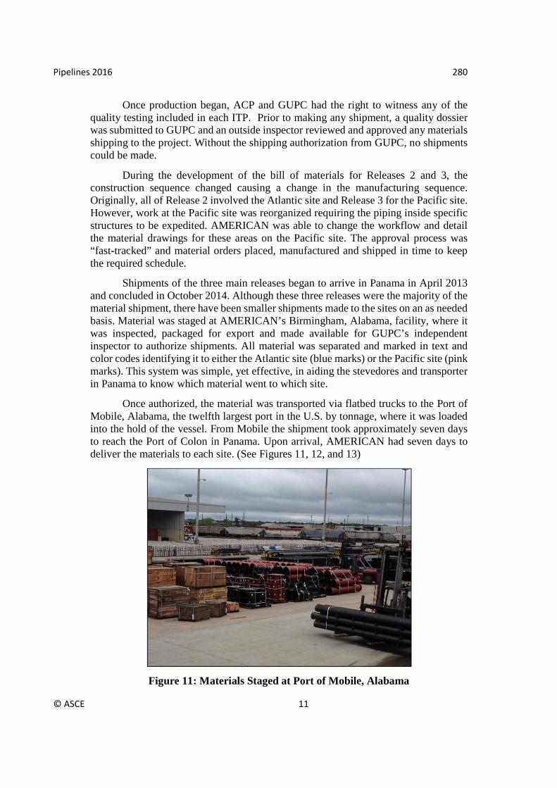
Once authorized, the material was transported via flatbed trucks to the Port of Mobile, Alabama, the twelfth largest port in the U.S. by tonnage, where it was loaded into the hold of the vessel. From Mobile the shipment took approximately seven days to reach the Port of Colon in Panama. Upon arrival, AMERICAN had seven days to deliver the materials to each site. (See Figures 11, 12, and 13)
Figure 11: Materials Staged at Port of Mobile, Alabama

Pipelines 2016 280
© ASCE 12
Figure 12: Ductile Iron Pipe Being Loaded at the Port of Mobile, Alabama
Figure 13: Installation of 30-inch and 24-inch Pipe at the Pacific Site

Pipelines 2016 280
© ASCE 13
UTILITY COORDINATION WITH 3D SOFTWARE
Coordination among global design centers that were simultaneously working on various portions of the infrastructure works was one of the toughest challenges of the project. MWH developed an Autodesk® Revit® based model that included most components of the works including the hydraulic structures, electrical systems, mechanical systems, storm drainage network, site grading and roadways. By utilizing the various Revit® products, the teams were able to collaborate in real time and have discussions on congested areas as multi-discipline deliverables were being submitted to ACP for review. As shown in Figure 14 below, there was limited space behind the lock chamber walls to locate the electrical, control, mechanical and drainage systems.
Figure 14: Typical Section and Screenshot of Navisworks® Model with Buried Utilities Shown
With more than 15 miles of ductile iron pipe, 50 miles of electrical duct banks, 10 miles of drainage pipe, associated manholes and equipment foundations, it was critical to coordinate the designs prior to construction so that field changes were minimized. In addition to the daily coordination between engineers and designers, weekly clash detection meetings were held that used the Clash Detective tool within Autodesk® Navisworks®. The set of clashes were reviewed by a representative from each discipline, and action items were defined and sent out at the end of each meeting. Figure 15 below shows an example of an interference that was detected between a fire hydrant and an electrical duct bank, and the final adjustment that was made to the fire hydrant to avoid the clash.
Figure 15: Screenshots of the Navisworks® Clash Detective Tool

Pipelines 2016 280
© ASCE 14
Design drawings were produced in the various Revit® models that included project specific parametric families that had information such as nomenclature, system, elevation, pipe diameter and length. The scheduled data for all the piping families was then exported to an Excel readable format, so that approximate quantities could be delivered to GUPC and AMERICAN for procurement purposes as the design was being developed and refined. Figure 16 below is a screenshot of project drawings that were produced in Revit® along with a schedule of pipe section lengths that updated automatically as designs progressed.
Figure 16: Screenshot of Revit® MEP with Project Drawings
In addition to utilizing the models through the design phase, they were extremely useful during the ESDC and QA portion of the work completed by MWH’s engineers. Portions of the model were exported to the Autodesk® BIM 360™ Glue®
application, so that engineers were able to review site progress with GUPC’s production team directly in the field with a tablet device. In addition, photographic logs of the site were taken daily, and the engineers had the capability to compare site progress with the Navisworks® model. If deviations were detected, the engineers used a combination of the model, site photos and design drawings to provide the production team with a clear definition of the deviation and solutions to repair it if needed. Figures 17 and 18 are examples of comparisons between the photographic logs and the design model.

Pipelines 2016 280
© ASCE 15
Figure 17: Screenshot of Navisworks® and Photo of Crossunder Thrust Supports
Figure 18: Screenshot of Navisworks® and Photo of 20-inch Buried Fire Protection Pipe
CONCLUSIONS
Collaboration among the contractor, designer and manufacturer with a spirit of cooperation and teamwork lead to a successful execution of the design and installation of the ductile iron pipe networks used on the Panama Canal Expansion - Third Set of Locks Project. All parties focused on the final objective to build a system complying with the Employer’s Requirements and established specifications while staying within budget. As with all construction projects, not all tasks go as planned and there must be flexibility and goodwill among the parties to find the most viable solutions to problems.
Strict adherence to the AWWA M41 Manual during the design stage of the pipeline allowed successful testing and commissioning of the various systems in accordance with AWWA C600 and C651 Standards. The dilemma of the high pressure 30-inch Crossunder piping was solved after performing prototype testing and in-line testing of production fabrications prior to being shipped to the site. The use of computer modeling for all the buried utilities and weekly clash detection meetings held over the course of several months eliminated more than 200 utility conflicts, which mitigated numerous potential construction issues and saved the project thousands of dollars in construction costs related to coordinating the extensive buried infrastructure.

Pipelines 2016 280
© ASCE 16
REFERENCES
American Pipe Manual. (2004). Flanged Pipe, Chapter 8, pg. 8-1. Nineteenth Edition, American Cast Iron Pipe Company, Birmingham, Alabama.
ANSI/AWWA C115/A21.15-05 (American National Standards Institute / American Water Works Association), Flanged Ductile-Iron Pipe with Ductile-Iron or Gray-Iron Threaded Flanges, 2006. AWWA Denver, Colorado.
ANSI/AWWA C600-10 (American National Standards Institute / American Water Works Association), Installation of Ductile-Iron Mains and Their Appurtenances, Effective date: November 1, 2010. AWWA Denver, Colorado.
ANSI/AWWA M41 (American National Standards Institute / American Water Works Association), Ductile-Iron Pipe and Fittings, 2009. AWWA Denver, Colorado.
DeBoalt, Steve, American Cast Iron Pipe Company internal test report, May 4, 2012. Panama Canal Authority, Design and Construction of the Third Set of Locks,
Employer’s Requirements, RFP-76161, February 2009. United States Department of Transportation, Office of the Assistant Secretary for
Research and Technology, Bureau of Transportation Statistics (2015). “National Transportation Statistics”, Table 1-57: Tonnage of Top 50 U.S. Water Ports, Ranked by Total Tons, http://www.rita.dot.gov/bts/sites/rita. dot.gov.bts/files/publications/national_transportation_statistics/html/table_01_57.html (October 2015)


![Ductile Iron Digest1]](https://img.dokumen.tips/doc/110x75/56d6c04d1a28ab301699d0b6/ductile-iron-digest1.jpg)