Embed Size (px)
Citation preview
Rio Tinto Iron & Titanium
DUCTILE IRONThe essentials of gating
and risering system designRevised in 2000
DUCTILE IRONThe essentials of gating
and risering system design
Published by:
770 Sherbrooke Street West – Suite 1800Montréal (Québec) CanadaH3A 1G1
Rio Tinto Iron & Titanium Inc.
FOREWORD .......................................................... 4
1.0 GATING SYSTEM DESIGN ........................ 6
1.1 Requirements .............................................. 6
1.2 Essential Components ................................ 6
1.3 Planning ...................................................... 6
1.4 The Role of “Choke” .................................... 6
1.5 Selection of Gating System Type ................ 7
1.6 Friction ........................................................ 7
1.7 Pouring Time ................................................ 8
1.8 Choke Cross Sectional Area ........................ 8
1.9 Choke Configuration .................................... 9
1.10 Sprue Design .............................................. 11
1.11 Runner Bar .................................................. 12
1.12 Gate Connection .......................................... 13
1.13 Pouring Basin and Sprue Well .................... 13
1.14 Common Defects Relating to Poor GatingSystem Design ............................................ 14
1.15 Case History ................................................ 15
1.16 Molten Metal Filtration .................................. 17
2.0 RISERING SYSTEM DESIGN .................... 19
2.1 Objectives .................................................... 20
2.2 Essential Components ................................ 20
2.3 The Following are Suggested by Researchand Supported by Industrial Experience .... 20
2.4 Typical Volume Change Patterns ................ 21
2.5 Planning ...................................................... 21
2.6 Cooling Rate ................................................ 22
2.7 Mould Quality .............................................. 23
2.8 Liquid Iron Processing ................................ 23
2.9 Selection of Risering Method ...................... 24
2.10 Pressure Control Risering ............................ 25
2.11 Bottle Riser .................................................. 28
2.12 Riserless Design .......................................... 30
2.13 Directly Applied Risering Design (DAR) .... 30
2.14 Selection of Pouring Temperature Basedon Risering Method .................................... 32
2.15 Pressure Control Risering & Bottle RiseringCase Histories ............................ 33-37, 41-43
2.16 Metallurgical Quality Control ...................... 38
2.17 Methods to measure Metal Quality .............. 38
2.18 Other Risering Aids .................................... 39
2.19 Chills ............................................................ 40
BIBLIOGRAPHY ...................................................... 44
3
TABLE OF CONTENTS
The importance of casting soundness and produc-tion economy, as influenced by gating and riseringpractice, has been recognized for many years byRIT’s producers of high purity iron QIT - Fer et TitaneInc. (QIT) and Richards Bay Iron and Titanium (Pty)Limited (RBIT). Indeed, it can be accurately describedas being a RIT tradition of interest and involvement inthis area of castings production. The pioneer in thiswork was Dr. Stephen I. Karsay and his book entitled“Ductile Iron III – Gating and Risering” has formed thebasis for this present seminar/lecture notes book.
In addition to Karsay’s groundwork, a number of otherRIT technical service personnel have made valuablecontributions towards RIT’s present approach to thetask of gating and risering. True to tradition, RIT hasclosely followed the results and experiences of othersworking in this field and, where appropriate, has incor-porated some of these into its presentations on thesubject.
This set of seminar/lecture notes forms the basis forgating and risering presentations which are regularlygiven around the world to groups of foundrymen atseminars and meetings organized either by RIT and itsagents or in conjunction with foundry organizations.The notes are not intended to be a comprehensivetreatment of the subject but rather to give the essen-tial features of RIT’s approach in a form, that is easy touse and apply. For those who require a more detailed,in depth, treatment of the subject, see the bibliography.RIT is indebted to the foundries and foundrymen whohave contributed in many ways over the years during the
continuing quest to arrive at a generally acceptable andsuccessful approach to the task of gating and riseringDuctile Iron castings.
RIT makes no claim to “have discovered the ultimateformulae”, but suggests that these notes provide a sen-sible and logical approach to a problem which dailyconfronts foundrymen – namely, the economic pro-duction of clean, sound Ductile Iron castings.
RIT has made every reasonable effort to ensure thatthe data presented accurately represents the informa-tion contained in the many sources from which it wasobtained and, when necessary, attempts have beenmade to reconcile data from different sources whichdo not agree. Therefore RIT believes that all informationgiven is accurate and is provided in good faith, butwithout any warranty, either express or implied. Thisbook is protected by copyright and no part of it can bereproduced, stored in a retrieval system or transmittedin any form or by any means without the prior writtenpermission of Rio Tinto Iron & Titanium Inc.
Copyright 2000 by Rio Tinto Iron & Titanium Inc.
4
FOREWORD

Section one
Gating System Design
Please note:
The reader should note that the risering of a casting mustbe done before the gating system is designed or calculationsmade.
1.0 GATING SYSTEM DESIGN
1.1 Requirements:• Fast pouring to: Minimize temperature loss during
mould filling.Minimize metallurgical “fade”.Minimize oxidation.
• Clean pouring to: Avoid slag (dross) generation duringpouring.Screen out slag from first iron poured into mould.
• Economic Design: Maximize casting yield.
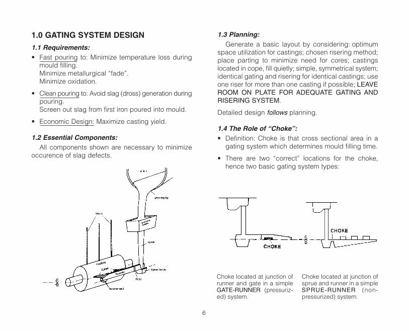
1.2 Essential Components:All components shown are necessary to minimize
occurence of slag defects.
1.3 Planning:Generate a basic layout by considering: optimum
space utilization for castings; chosen risering method;place parting to minimize need for cores; castingslocated in cope, fill quietly; simple, symmetrical system;identical gating and risering for identical castings; useone riser for more than one casting if possible; LEAVEROOM ON PLATE FOR ADEQUATE GATING ANDRISERING SYSTEM.
Detailed design follows planning.
1.4 The Role of “Choke”:• Definition: Choke is that cross sectional area in a
gating system which determines mould filling time.
• There are two “correct” locations for the choke,hence two basic gating system types:
6
Choke located at junction ofrunner and gate in a simpleGATE-RUNNER (pressuriz-ed) system.
Choke located at junction ofsprue and runner in a simpleSPRUE-RUNNER (non-pressurized) system.
1.5 Selection of Gating System Type:• In a GATE-RUNNER system castings are choked
individually by one or more chokes or gates. With aSPRUE-RUNNER system it is possible for severalcastings to share a common choke.
• Use SPRUE-RUNNER system for large number of small castings in one mould where it is impracticalto choke the castings individually – where chokedimensions are very small – very demanding onmoulding technique and pouring temperature.
• Use GATE-RUNNER system on most other occa-sions.
• Features of GATE-RUNNER and SPRUE-RUNNERSYSTEMS can be combined to form a HYBRID sys-tem. This is normally used where a complicatednetwork of runners is required to deliver iron tocasting cavities.
1.6 Friction:• Not all potential energy of liquid at top of sprue is
converted to mechanical energy at casting cavity.
• Some potential energy lost to friction (heat) as li-quid moves against mould wall and liquid movesagainst liquid.
• Energy loss due to friction extends mould fillingtime and must be taken into account whencalculating choke cross sectional area and pouringtime.
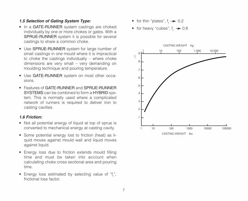
• Energy loss estimated by selecting value of “fr”,frictional loss factor.
• for thin “plates”, fr 0.2
• for heavy “cubes”, fr 0.8
7
CASTING WEIGHT Kg.
CASTING WEIGHT lbs
fr
1 10 100 1,000 10,000.9
.8
.7
.6
.5
.4
.3
.2
.1
1 10 100 1000 10000 100000
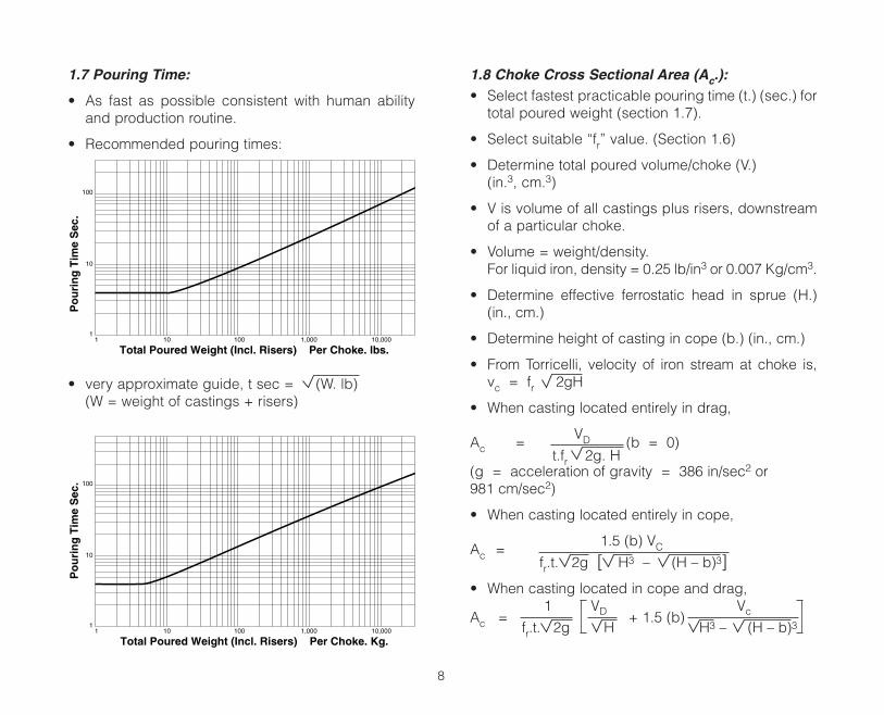
1.7 Pouring Time:
• As fast as possible consistent with human abilityand production routine.
• Recommended pouring times:
• very approximate guide, t sec = (W. lb)(W = weight of castings + risers)
1.8 Choke Cross Sectional Area (Ac.):• Select fastest practicable pouring time (t.) (sec.) for
total poured weight (section 1.7).
• Select suitable “fr” value. (Section 1.6)
• Determine total poured volume/choke (V.)(in.3, cm.3)
• V is volume of all castings plus risers, downstreamof a particular choke.
• Volume = weight/density.For liquid iron, density = 0.25 lb/in3 or 0.007 Kg/cm3.
• Determine effective ferrostatic head in sprue (H.)(in., cm.)
• Determine height of casting in cope (b.) (in., cm.)
• From Torricelli, velocity of iron stream at choke is,vc = fr 2gH
• When casting located entirely in drag,
VDAc = (b = 0)t.fr 2g. H
(g = acceleration of gravity = 386 in/sec2 or981 cm/sec2)
• When casting located entirely in cope,
1.5 (b) VCAc =fr.t. 2g [ H3 – (H – b)3]
• When casting located in cope and drag,1 VD + 1.5 (b)
VcAc =fr.t. 2g H H3 – (H – b)3
8
Total Poured Weight (Incl. Risers) Per Choke. lbs.
Po
uri
ng
Tim
e S
ec.
100
10
11 10 100 1,000 10,000
Total Poured Weight (Incl. Risers) Per Choke. Kg.
Po
uri
ng
Tim
e S
ec. 100
10
11 10 100 1,000 10,000
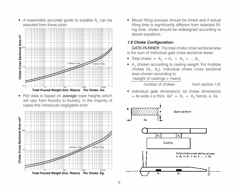
• A reasonably accurate guide to suitable Ac can beselected from these plots:
• Plot data is based on average cope heights whichwill vary from foundry to foundry. In the majority ofcases this introduces negligable error.
• Mould filling process should be timed and if actualfilling time is significantly different from selected fill-ing time, choke should be redesigned according toabove equations.
1.9 Choke Configuration:GATE-RUNNER: The total choke cross sectional area
is the sum of individual gate cross sectional areas:
• Total choke = Ac = A1 + A2 + ... An
• Ac chosen according to casting weight. For multiplechokes (A1, A2), individual choke cross sectionalarea chosen according to(weight of castings + risers)
number of chokes from section 1.8.
• Individual gate dimensions: let choke dimensions= 4a wide x a thick. 4a2 = A1 = A2 hence, a, 4a.
9
Total Poured Weight (Incl. Risers) Per Choke. lbs.
Ch
oke
Cro
ss S
ecti
on
al A
rea
in2
10.0
1.0
0.11 10 100 1,000 10,000
Casting in Cope Casting in Drag
Total Poured Weight (Incl. Risers) Per Choke. Kg.
Ch
oke
Cro
ss S
ecti
on
al A
rea
cm2
100
10
11 10 100 1,000 10,000
Casting in Cope Casting in Drag
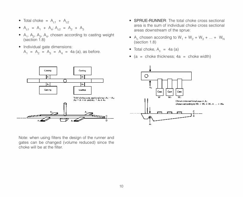
• Total choke = Ac1 + Ac2
• Ac1 = A1 + A4; Ac2 = A2 + A3
• A1, A2, A3, A4, chosen according to casting weight(section 1.8)
• Individual gate dimensions:A1 = A2 = A3 = A4 = 4a (a), as before.
Note: when using filters the design of the runner andgates can be changed (volume reduced) since thechoke will be at the filter.
• SPRUE-RUNNER: The total choke cross sectionalarea is the sum of individual choke cross sectionalareas downstream of the sprue:
• Ac chosen according to W1 + W2 + W3 + ... + WN(section 1.8)
• Total choke, Ac = 4a (a)
• (a = choke thickness; 4a = choke width)
10
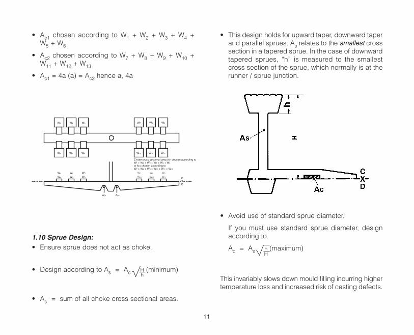
• Ac1 chosen according to W1 + W2 + W3 + W4 +W5 + W6
• Ac2 chosen according to W7 + W8 + W9 + W10 +W11 + W12 + W13
• Ac1 = 4a (a) = Ac2 hence a, 4a
1.10 Sprue Design:• Ensure sprue does not act as choke.
• Design according to As = Ac H (minimum)h
• Ac = sum of all choke cross sectional areas.
• This design holds for upward taper, downward taperand parallel sprues. As relates to the smallest crosssection in a tapered sprue. In the case of downwardtapered sprues, “h” is measured to the smallestcross section of the sprue, which normally is at therunner / sprue junction.
• Avoid use of standard sprue diameter.
If you must use standard sprue diameter, designaccording to
Ac = As h (maximum)H
This invariably slows down mould filling incurring highertemperature loss and increased risk of casting defects.
11
W1
W4
W1
W4
W5 W6
W2 W3 W7
W10 W11 W12
W8 W9
CXD
W2
W5
W3
W6
W7
Choke cross sectional area AC1 chosen according toW1 + W2 + W3 + W4 + W5 + W6
or AC2 chosen according toW7 + W8 + W9 + W10 + W11 + W12
AC1 AC2
W10
W8
W11
W9
W12
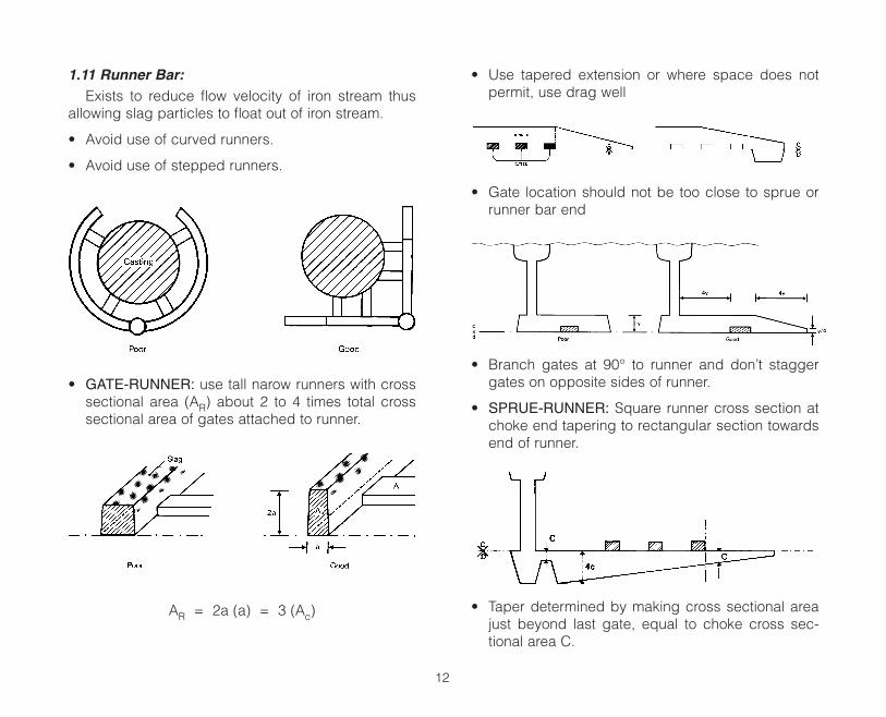
1.11 Runner Bar:Exists to reduce flow velocity of iron stream thus
allowing slag particles to float out of iron stream.
• Avoid use of curved runners.
• Avoid use of stepped runners.
• GATE-RUNNER: use tall narow runners with crosssectional area (AR) about 2 to 4 times total crosssectional area of gates attached to runner.
AR = 2a (a) = 3 (Ac)
• Use tapered extension or where space does notpermit, use drag well
• Gate location should not be too close to sprue orrunner bar end
• Branch gates at 90° to runner and don’t staggergates on opposite sides of runner.
• SPRUE-RUNNER: Square runner cross section atchoke end tapering to rectangular section towardsend of runner.
• Taper determined by making cross sectional areajust beyond last gate, equal to choke cross sec-tional area C.
12
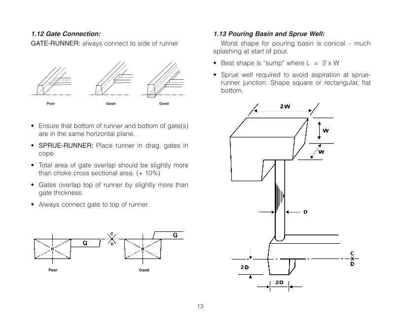
1.12 Gate Connection:GATE-RUNNER: always connect to side of runner
• Ensure that bottom of runner and bottom of gate(s)are in the same horizontal plane.
• SPRUE-RUNNER: Place runner in drag, gates incope.
• Total area of gate overlap should be slightly morethan choke cross sectional area. (+ 10%)
• Gates overlap top of runner by slightly more thangate thickness.
• Always connect gate to top of runner.
1.13 Pouring Basin and Sprue Well:Worst shape for pouring basin is conical – much
splashing at start of pour.
• Best shape is “sump” where L = 2 x W
• Sprue well required to avoid aspiration at sprue-runner junction. Shape square or rectangular, flatbottom.
13
Poor GoodGood
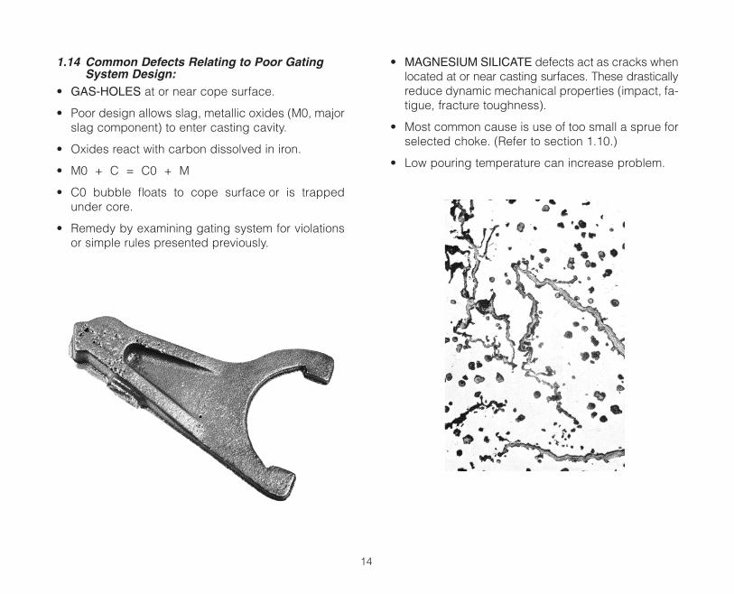
1.14 Common Defects Relating to Poor GatingSystem Design:
• GAS-HOLES at or near cope surface.
• Poor design allows slag, metallic oxides (M0, majorslag component) to enter casting cavity.
• Oxides react with carbon dissolved in iron.
• M0 + C = C0 + M
• C0 bubble floats to cope surface or is trappedunder core.
• Remedy by examining gating system for violationsor simple rules presented previously.
• MAGNESIUM SILICATE defects act as cracks whenlocated at or near casting surfaces. These drasticallyreduce dynamic mechanical properties (impact, fa-tigue, fracture toughness).
• Most common cause is use of too small a sprue forselected choke. (Refer to section 1.10.)
• Low pouring temperature can increase problem.
14
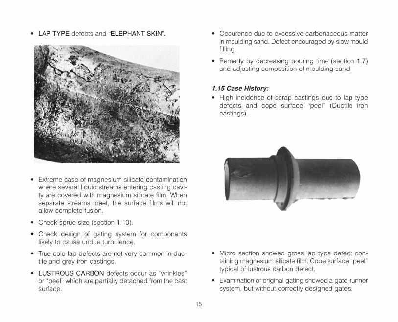
• LAP TYPE defects and “ELEPHANT SKIN”.
• Extreme case of magnesium silicate contaminationwhere several liquid streams entering casting cavi-ty are covered with magnesium silicate film. Whenseparate streams meet, the surface films will notallow complete fusion.
• Check sprue size (section 1.10).
• Check design of gating system for componentslikely to cause undue turbulence.
• True cold lap defects are not very common in duc-tile and grey iron castings.
• LUSTROUS CARBON defects occur as “wrinkles”or “peel” which are partially detached from the castsurface.
• Occurence due to excessive carbonaceous matterin moulding sand. Defect encouraged by slow mouldfilling.
• Remedy by decreasing pouring time (section 1.7)and adjusting composition of moulding sand.
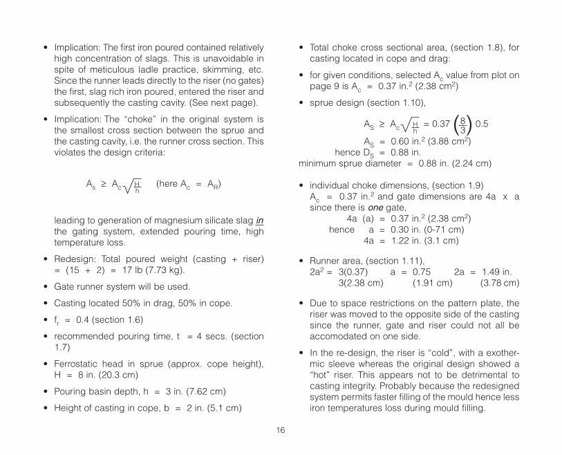
1.15 Case History:• High incidence of scrap castings due to lap type
defects and cope surface “peel” (Ductile ironcastings).
• Micro section showed gross lap type defect con-taining magnesium silicate film. Cope surface “peel”typical of lustrous carbon defect.
• Examination of original gating showed a gate-runnersystem, but without correctly designed gates.
15
• Implication: The first iron poured contained relativelyhigh concentration of slags. This is unavoidable inspite of meticulous ladle practice, skimming, etc.Since the runner leads directly to the riser (no gates)the first, slag rich iron poured, entered the riser andsubsequently the casting cavity. (See next page).
• Implication: The “choke” in the original system isthe smallest cross section between the sprue andthe casting cavity, i.e. the runner cross section. Thisviolates the design criteria:
As ≥ Ac H (here Ac = AR)h
leading to generation of magnesium silicate slag inthe gating system, extended pouring time, hightemperature loss.
• Redesign: Total poured weight (casting + riser)= (15 + 2) = 17 lb (7.73 kg).
• Gate runner system will be used.
• Casting located 50% in drag, 50% in cope.
• fr = 0.4 (section 1.6)
• recommended pouring time, t = 4 secs. (section1.7)
• Ferrostatic head in sprue (approx. cope height),H = 8 in. (20.3 cm)
• Pouring basin depth, h = 3 in. (7.62 cm)
• Height of casting in cope, b = 2 in. (5.1 cm)
• Total choke cross sectional area, (section 1.8), forcasting located in cope and drag:
• for given conditions, selected Ac value from plot onpage 9 is Ac = 0.37 in.2 (2.38 cm2)
• sprue design (section 1.10),
AS ≥ Ac H = 0.37 (8) 0.5h 3
AS = 0.60 in.2 (3.88 cm2)hence DS = 0.88 in.
minimum sprue diameter = 0.88 in. (2.24 cm)
• individual choke dimensions, (section 1.9)Ac = 0.37 in.2 and gate dimensions are 4a x asince there is one gate,
4a (a) = 0.37 in.2 (2.38 cm2)hence a = 0.30 in. (0-71 cm)
4a = 1.22 in. (3.1 cm)
• Runner area, (section 1.11),2a2 = 3(0.37) a = 0.75 2a = 1.49 in.
3(2.38 cm) (1.91 cm) (3.78 cm)
• Due to space restrictions on the pattern plate, theriser was moved to the opposite side of the castingsince the runner, gate and riser could not all beaccomodated on one side.
• In the re-design, the riser is “cold”, with a exother-mic sleeve whereas the original design showed a“hot” riser. This appears not to be detrimental tocasting integrity. Probably because the redesignedsystem permits faster filling of the mould hence lessiron temperatures loss during mould filling.
16
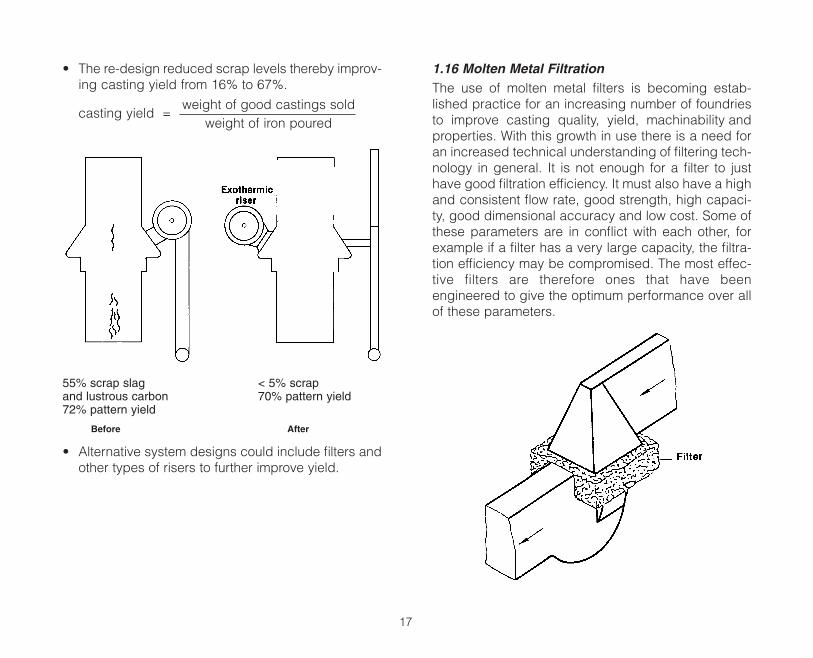
• The re-design reduced scrap levels thereby improv-ing casting yield from 16% to 67%.
casting yield =weight of good castings sold
weight of iron poured
55% scrap slag < 5% scrapand lustrous carbon 70% pattern yield72% pattern yield
Before After
• Alternative system designs could include filters andother types of risers to further improve yield.
1.16 Molten Metal FiltrationThe use of molten metal filters is becoming estab-lished practice for an increasing number of foundriesto improve casting quality, yield, machinability andproperties. With this growth in use there is a need foran increased technical understanding of filtering tech-nology in general. It is not enough for a filter to justhave good filtration efficiency. It must also have a highand consistent flow rate, good strength, high capaci-ty, good dimensional accuracy and low cost. Some ofthese parameters are in conflict with each other, forexample if a filter has a very large capacity, the filtra-tion efficiency may be compromised. The most effec-tive filters are therefore ones that have beenengineered to give the optimum performance over allof these parameters.
17
There are several established filter technologies pre-sently on the market. These include strainer cores, wovencloth or mesh, and ceramic tile filters. Ceramic tile fil-ters are generally considered to be the most effectiveand used for smaller molds & pours. The most popularof these are pressed cellular, extruded cellular and foamfilters. Pressed cellular are generally characterized bytheir round cells, extruded filters generally have squarecells, whilst foam filters have a random dodecahedrontype structure.
• Filtration Efficiency is important to remove slag anddross from the iron to prevent them from enteringthe mold cavity.
• Metal Capacity must be adequate for the castingbut it should also be consistent. The capacity shouldnot vary from filter to filter. This may lead to prema-ture blockage in some cases.
• Flow Rate must be high and consistent. Wide vari-ations in flow rate may in some cases, lead to moldfill problems, or a requirement to use a larger filterthereby increasing cost and decreasing yield.
• Dimensional Accuracy is important because the fil-ters should fit into their print cavity correctly eachtime.
• Strength (hot or cold) is important for shipping andhandling purposes and so the filter remains intactwhen molten metal is poured onto it.
Filters do a good job of removing inclusions using avariety of mechanisms. Some types may be more effi-cient at one mechanism than another. Filters will collect
dross particles and inclusions by screening, that arelarger than the filter hole or pore size, on their upstreamface. These particles are unable to pass through to thecasting cavity due to their physical size. Secondly, largedross particles collected on the upstream face duringthe screening phase will form what is known as a “fil-ter cake”. This cake acts as an efficient filtrationmedia. This mechanism is able to collect particlessmaller than the cells of the filter. In ductile iron, it ispossible that the mechanism for the removal of micro-inclusions, (<1% of the cell size), is through the for-mation of “inclusion bridges”. Small eddy currents,formed when the metal stream splits on the activeface of the filter, are generated. These eddy currentswill encourage small non-metallic particles to makecontact with the edges of the cell. As the pour pro-gresses these particles will continue to adhere to eachother and will eventually form an “inclusion bridge”.
The use of the filters has increased dramatically in thepast 10 years as the cost per unit has decreased whilecasting wall thickness has been reduced and generalquality requirements for castings have increased. How-ever, as always, some experimentation must be donein the foundry to establish proper filter sizes, ladle des-lagging practices and pouring temperature ranges sothat good casting yield is maintained.
18