Embed Size (px)
Citation preview

DTV Design Library
August 2005
Notice
The information contained in this document is subject to change without notice.
Agilent Technologies makes no warranty of any kind with regard to this material,including, but not limited to, the implied warranties of merchantability and fitnessfor a particular purpose. Agilent Technologies shall not be liable for errors containedherein or for incidental or consequential damages in connection with the furnishing,performance, or use of this material.
Warranty
A copy of the specific warranty terms that apply to this software product is availableupon request from your Agilent Technologies representative.
Restricted Rights Legend
Use, duplication or disclosure by the U. S. Government is subject to restrictions as setforth in subparagraph (c) (1) (ii) of the Rights in Technical Data and ComputerSoftware clause at DFARS 252.227-7013 for DoD agencies, and subparagraphs (c) (1)and (c) (2) of the Commercial Computer Software Restricted Rights clause at FAR52.227-19 for other agencies.
© Agilent Technologies, Inc. 1983-2005395 Page Mill Road, Palo Alto, CA 94304 U.S.A.
Acknowledgments
Mentor Graphics is a trademark of Mentor Graphics Corporation in the U.S. andother countries.
Microsoft®, Windows®, MS Windows®, Windows NT®, and MS-DOS® are U.S.registered trademarks of Microsoft Corporation.
Pentium® is a U.S. registered trademark of Intel Corporation.
PostScript® and Acrobat® are trademarks of Adobe Systems Incorporated.
UNIX® is a registered trademark of the Open Group.
Java™ is a U.S. trademark of Sun Microsystems, Inc.
SystemC® is a registered trademark of Open SystemC Initiative, Inc. in the UnitedStates and other countries and is used with permission.
ii

Contents1 DTV Design Library
Introduction............................................................................................................... 1-1ISDB-T System......................................................................................................... 1-1DVB-T System .......................................................................................................... 1-2OFDM Technique...................................................................................................... 1-3Glossary of Terms .................................................................................................... 1-5References ............................................................................................................... 1-6
2 Channel Coding ComponentsDTV_BCHCoder ....................................................................................................... 2-2DTV_BCHDecoder ................................................................................................... 2-5DTV_ConvCoder ...................................................................................................... 2-10DTV_ConvCoder1_2 ................................................................................................ 2-12DTV_ConvDecoder .................................................................................................. 2-14DTV_ConvDecoder1_2 ............................................................................................ 2-17DTV_Delay ............................................................................................................... 2-19DTV_Demapper........................................................................................................ 2-20DTV_DQPSKCoder .................................................................................................. 2-23DTV_DQPSKDecoder .............................................................................................. 2-25DTV_InnerDecoder................................................................................................... 2-27DTV_InterlvFloat....................................................................................................... 2-29DTV_InterlvInt........................................................................................................... 2-31DTV_ISDBChCoder.................................................................................................. 2-34DTV_ISDBChDecoder.............................................................................................. 2-36DTV_ISDBDerandomize........................................................................................... 2-38DTV_ISDBRandomize.............................................................................................. 2-40DTV_Mapper ............................................................................................................ 2-43DTV_PNreset ........................................................................................................... 2-49DTV_PuncCoder ...................................................................................................... 2-51DTV_PuncConvCoder .............................................................................................. 2-53DTV_PuncConvDecoder .......................................................................................... 2-55DTV_PuncDecoder................................................................................................... 2-58DTV_QAM16Coder .................................................................................................. 2-60DTV_QAM16Decoder............................................................................................... 2-63DTV_QAM64Coder .................................................................................................. 2-65DTV_QAM64Decoder............................................................................................... 2-69DTV_QPSKCoder..................................................................................................... 2-71DTV_QPSKDecoder................................................................................................. 2-73DTV_RSCoder.......................................................................................................... 2-74DTV_RSDecoder...................................................................................................... 2-78
iii

DTV_ScrambleByte .................................................................................................. 2-84
3 DVB-H ComponentsDTV_DVBHHierReceiver .......................................................................................... 3-2DTV_DVBHHierReceiver_RF ................................................................................... 3-9DTV_DVBHHierSignalSrc......................................................................................... 3-17DTV_DVBHHierSignalSrc_RF.................................................................................. 3-22DTV_DVBHInnerDeinterlv ........................................................................................ 3-29DTV_DVBHInnerInterlv............................................................................................. 3-36DTV_DVBHReceiver................................................................................................. 3-43DTV_DVBHReceiver_RF.......................................................................................... 3-48DTV_DVBHSignalSrc ............................................................................................... 3-54DTV_DVBHSignalSrc_RF ........................................................................................ 3-58DTV_DVBHTPS........................................................................................................ 3-64
4 DVB-T ComponentsDTV_CIRNorm ......................................................................................................... 4-2DTV_DVB2DChEstimator......................................................................................... 4-4DTV_DVBBitBlockInterlv .......................................................................................... 4-9DTV_DVBChannel.................................................................................................... 4-11DTV_DVBChEstimator ............................................................................................. 4-14DTV_DVBDemuxOFDMSym .................................................................................... 4-18DTV_DVBLoadIFFTBuff ........................................................................................... 4-23DTV_DVBMuxOFDMSym......................................................................................... 4-25DTV_DVBSymDeinterlv2b........................................................................................ 4-29DTV_DVBSymDeinterlv4b........................................................................................ 4-31DTV_DVBSymDeinterlv6b........................................................................................ 4-33DTV_DVBSymInterlv2b ............................................................................................ 4-35DTV_DVBSymInterlv4b ............................................................................................ 4-39DTV_DVBSymInterlv6b ............................................................................................ 4-41DTV_DVBSymInterlvCx............................................................................................ 4-43DTV_DVBTHierInnerDeInterlv.................................................................................. 4-45DTV_DVBTHierInnerInterlv ...................................................................................... 4-47DTV_DVBTHierReceiver .......................................................................................... 4-49DTV_DVBTHierReceiver_RF.................................................................................... 4-56DTV_DVBTHierSignalSrc ......................................................................................... 4-65DTV_DVBTHierSignalSrc_RF .................................................................................. 4-70DTV_DVBTImpulseNoise ......................................................................................... 4-76DTV_DVBTInnerDeInterlv ........................................................................................ 4-79DTV_DVBTInnerInterlv ............................................................................................. 4-81DTV_DVBTOFDMDemod ......................................................................................... 4-83DTV_DVBTOFDMMod.............................................................................................. 4-88DTV_DVBTPS .......................................................................................................... 4-93
iv

DTV_DVBTPSDemod............................................................................................... 4-97DTV_DVBTPSMod ................................................................................................... 4-99DTV_DVBTReceiver ................................................................................................. 4-101DTV_DVBTReceiver_RF .......................................................................................... 4-107DTV_DVBTSignalSrc................................................................................................ 4-114DTV_DVBTSignalSrc_RF......................................................................................... 4-118DTV_DVBTTPSGen ................................................................................................. 4-124DTV_DVBTTSPsource ............................................................................................. 4-130DTV_PALSource....................................................................................................... 4-133
5 ISDB-T ComponentsDTV_CDSCDecoder................................................................................................. 5-2DTV_CarrierRotator.................................................................................................. 5-6DTV_CarrierScrambler ............................................................................................. 5-8DTV_ChEstimator..................................................................................................... 5-13DTV_DemuxCohSegs .............................................................................................. 5-18DTV_DemuxDiffSegs ............................................................................................... 5-24DTV_DemuxTMCC................................................................................................... 5-31DTV_InterSegInterlv ................................................................................................. 5-33DTV_ISDBDemodulation.......................................................................................... 5-35DTV_ISDBFreqDeinterlv .......................................................................................... 5-38DTV_ISDBFreqInterlv ............................................................................................... 5-40DTV_ISDBOFDMDemod_ThreeLay......................................................................... 5-42DTV_ISDBOFDMDemod_TwoLay............................................................................ 5-45DTV_ISDBOFDMMod_ThreeLay ............................................................................. 5-48DTV_ISDBOFDMMod_TwoLay ................................................................................ 5-53DTV_LFSRCoder ..................................................................................................... 5-57DTV_LoadIFFTBuff .................................................................................................. 5-60DTV_ISDBModulation .............................................................................................. 5-62DTV_MuxCohSegs................................................................................................... 5-65DTV_MuxDiffSegs .................................................................................................... 5-71DTV_ISDBMuxSegs ................................................................................................. 5-78DTV_ISDBOFDMDemod_OneLay ........................................................................... 5-80DTV_ISDBOFDMMod_OneLay................................................................................ 5-83DTV_ISDBOneLayReceiver ..................................................................................... 5-85DTV_ISDBOneLayReceiver_RF............................................................................... 5-90DTV_ISDBOneLaySource ........................................................................................ 5-96DTV_ISDBOneLaySource_RF ................................................................................. 5-100DTV_ISDBPartialReceiver_RF................................................................................. 5-106DTV_ISDBTMCC...................................................................................................... 5-111DTV_ISDBTSPSource.............................................................................................. 5-119DTV_ISDBThreeLayReceiver................................................................................... 5-121
v

DTV_ISDBThreeLayReceiver_RF ............................................................................ 5-127DTV_ISDBThreeLaySource ..................................................................................... 5-134DTV_ISDBThreeLaySource_RF............................................................................... 5-138DTV_ISDBTimeInterlv .............................................................................................. 5-144DTV_ISDBTwoLayFreqDeinterlv .............................................................................. 5-146DTV_ISDBTwoLayFreqInterlv ................................................................................... 5-148DTV_ISDBTwoLayReceiver...................................................................................... 5-150DTV_ISDBTwoLayReceiver_RF ............................................................................... 5-155DTV_ISDBTwoLaySource......................................................................................... 5-161DTV_ISDBTwoLaySource_RF.................................................................................. 5-165DTV_PackTMCC ...................................................................................................... 5-171DTV_TMCCDemod .................................................................................................. 5-173DTV_TMCCInfo ........................................................................................................ 5-175DTV_TMCCMod ....................................................................................................... 5-185DTV_TimeInterlv....................................................................................................... 5-187
6 Multiplex ComponentsDTV_CommCtrl2 ...................................................................................................... 6-2DTV_CommCtrl3 ...................................................................................................... 6-3DTV_DistCtrl2........................................................................................................... 6-4DTV_DistCtrl3........................................................................................................... 6-5DTV_SplitThreeLayData........................................................................................... 6-6DTV_SplitThreeLayTSP ........................................................................................... 6-8DTV_SplitTwoLayData.............................................................................................. 6-11DTV_SplitTwoLayTSP .............................................................................................. 6-13DTV_SynLayTMCC1 ................................................................................................ 6-16DTV_SynLayTMCC2 ................................................................................................ 6-18DTV_SynLayTMCC3 ................................................................................................ 6-20DTV_SynThreeLayData ........................................................................................... 6-22DTV_SynThreeLayTSP ............................................................................................ 6-24DTV_SynTwoLayData............................................................................................... 6-27DTV_SynTwoLayTSP ............................................................................................... 6-29
7 OFDM ComponentsDTV_AddFixPhase ................................................................................................... 7-2DTV_InsertGuard ..................................................................................................... 7-4DTV_LoadFFTBuff ................................................................................................... 7-6DTV_MLEstimator .................................................................................................... 7-11DTV_OFDMEqualizer............................................................................................... 7-14DTV_RemovePhase................................................................................................. 7-16
8 Test ComponentsDTV_BER................................................................................................................. 8-2
vi

DTV_PowerMeasure ................................................................................................ 8-4
9 DVB-H System Design ExamplesIntroduction............................................................................................................... 9-1DTV DVB-H Hierarchical Transmission..................................................................... 9-2DTV DVB-H Non-Hierarchical Transmission............................................................. 9-5
10 DVB-T System Design ExamplesIntroduction............................................................................................................... 10-1DTV OFDM............................................................................................................... 10-2
OFDM 16-QAM Modulation and Demodulation in DVB-T Systems.................... 10-2OFDM 64-QAM Modulation and Demodulation in DVB-T Systems.................... 10-8OFDM, 64-QAM DTV and PAL Signal Interference Test in DTV Systems ......... 10-15
DTV DVB System ..................................................................................................... 10-20OFDM 16-QAM DVB-T System without Channel Coding BER .......................... 10-2016-QAM DVB-T System Design ......................................................................... 10-28Hierarchical 64-QAM DVB-T System Design ..................................................... 10-40
11 DVB-T Receiver Design ExamplesIntroduction............................................................................................................... 11-1DVB-T AWGN Performance...................................................................................... 11-3DVB-T Digital Adjacent Channel Performance ......................................................... 11-7DVB-T Impulse Interference Performance ................................................................ 11-14DVB-T Long Delay Channel Performance ................................................................ 11-19DVB-T Analog Adjacent Channel Performance ........................................................ 11-23DVB-T Analog Co-Channel Performance ................................................................. 11-29DVB-T Image Channel Performance ........................................................................ 11-36DVB-T Rayleigh Channel (P1) Performance............................................................. 11-40DVB-T Ricean Channel (F1) Performance ............................................................... 11-45DVB-T Receiver Minimum Input Level Sensitivity..................................................... 11-49DVB-T Short Delay Channel Performance ............................................................... 11-54DVB-T Single Echo Channel Performance ............................................................... 11-58
12 ISDB-T System Design ExamplesIntroduction............................................................................................................... 12-1DTV ISDB Project Examples .................................................................................... 12-2
DTV ISDB Demo for 1-Layer System ................................................................. 12-3DTV ISDB Demo for 2-Layer System ................................................................. 12-6DTV ISDB Demo for 3-Layer System ................................................................. 12-9DTV ISDB Demo for Partial Reception System.................................................. 12-12
DTV ISDB OFDM Project Example .......................................................................... 12-15OFDM 64-QAM Modulation and Demodulation in ISDB-T Systems .................. 12-16OFDM DQPSK Modulation and Demodulation in ISDB-T Systems ................... 12-22DTV and NTSC Signal Interference Test in ISDB-T Systems ............................ 12-28
vii

OFDM 2-Layer Modulation and Demodulation in ISDB-T Systems.................... 12-34OFDM 3-Layer Modulation and Demodulation in ISDB-T Systems.................... 12-39
DTV ISDB System Project Examples ....................................................................... 12-45OFDM 64-QAM ISDB-T System without Channel Coding BER ......................... 12-46OFDM DQPSK ISDB-T System without Channel Coding BER.......................... 12-511-Layer 64-QAM Mapping ISDB-T System Design ............................................ 12-561-Layer DQPSK-Mapping ISDB-T System Design............................................. 12-673-Layer ISDB-T System Design ......................................................................... 12-772-Layer ISDB-T System Design ......................................................................... 12-85TMCC in ISDB-T 1-Layer System Design .......................................................... 12-93TMCC in ISDB-T 3-Layer System Design .......................................................... 12-98
Index
viii

Chapter 1: DTV Design Library
IntroductionThe Agilent EEsof DTV Design Library includes the current Japanese, and EuropeanHDTV standards for the Advanced Design System platform. This design libraryfocuses on the transmission layer of the HDTV system and is intended to be abaseline system for designers to get an idea of what a nominal or ideal systemperformance would be. They also provide determination of degraded systemperformance due to system impairments that may include nonideal componentperformance.
ISDB-T SystemThe ISDB-T system has been designed to have the flexibility to send television orsound programs as digital signals while offering multimedia services in which avariety of digital information (video, sound, text and computer programs) can beintegrated. It aims to make use of the advantages provided by terrestrial radio wavesso that stable reception can be provided by compact, light and inexpensive mobilereceivers in addition to integrated receivers used at home by using a BST(bandsegmented transmission)-OFDM scheme [1].
Two transmission bandwidths are prescribed (5.6 MHz and 432 kHz), each orientedto particular types of broadcasting services. The 5.6-MHz bandwidth is primarily fordigital broadcasting of television programs; the 432-kHz bandwidth is primarily foraudio programs. These two modes share all other parameters such as encodingformat, multiplexing format, and OFDM carrier interval and frame configuration.
Terrestrial ISDB provides hierarchical transmission features using different carriermodulation schemes (DQPSK, QPSK, 16-QAM, 64-QAM) and internal encoding rates(1/2, 2/3, 3/4, 5/6, 7/8). This enables part of the band to be allocated to signals forstationary reception and the rest to signals for mobile reception; this means audioand data broadcasts for automobile and portable receivers can be performedsimultaneously with television broadcasts for home use. Each hierarchical level canbe set for each BST segment having a bandwidth of 432 kHz. Such information can besent to receivers by TMCC (transmission and multiplexing configuration control)signal allocated to part of the OFDM carrier.
Introduction 1-1

DTV Design Library
Because the wide and narrow bandwidths in terrestrial ISDB share the same OFDMparameters, the 5.6-MHz wide band can directly include the 432-kHz narrow band.Consequently, a 432-kHz receiver can receive some 5.6-MHz services, and a 5.6-MHzreceiver can receive all services broadcast at 432 kHz.
Based on the system configuration, this design library may include threesub-libraries, transmission, receiving and channel coding sub-libraries.
DVB-T SystemThe DVB-T system was designed with the flexibility to adapt to all channelsincluding clear channels and interleaved planning, and co-channel operation for thesame program by different transmitters (single-frequency networks).
It also permits service flexibility, with the possibility of reception by roof-topantennae and portable reception, if necessary. Mobile reception is possible for QPSKand for higher modulation orders, as proven by extensive laboratory measurementsand field trials under different channel conditions.
The system was also designed to be robust against interference from delayed signals,either echoes from terrain or buildings or signals from distant transmitters in asingle frequency network, a new tool which it brings to TV service planning toimprove spectrum efficiency which is necessary in the case of particularly crowdedspectrum as it is the case in Europe.
The DVB-T compliant signals can also be carried over cables. However, the DVB-Tspecification is part of a family of specifications covering also satellite (DVB-S) andcable (DVB-C) operation. All use MPEG-2 coding for video and audio and MPEG-2type of multiplexing. They have common features in the error protection strategy tobe used. The main difference is the modulation method that is specific to the relevantbearer (satellite, cable, or terrestrial). The available data capacity is also different, ashigher bit rates are offered on cable and satellite. However, transferring programsfrom one bearer to another is possible provided that the bit rate is available.
The DVB-T system features a number of selectable parameters so it canaccommodate a large range of carrier-to-noise ratio and channel behavior, enablingfixed, portable, or mobile reception, with a trade-off in the usable bit rate. The rangeof parameters lets broadcasters select a mode appropriate to the application. Forexample, a very robust mode (with correspondingly lower payload) is needed toensure portable reception. A moderately robust mode with a higher payload could beused where the service planning uses interleaved channels. The less robust modes
1-2 DVB-T System

with the highest payloads can be used if a clear channel is available for digital TVbroadcasting.
The DVB-T system also provides additional features to support handheld terminalstransmitting DVB-H services.
OFDM TechniqueMulti-carrier, or orthogonal frequency-division multiplexing (OFDM), systems havegained in interest during the last years. It is used in the European digital broadcastradio system, and its use in wireless applications such as digital broadcast televisionand mobile communication systems is currently being investigated. By the name ofdiscrete multi-tone (DMT) modulation, OFDM is also being examined for broadbanddigital communication on existing copper networks. The OFDM technique has beenproposed for high bit-rate digital subscriber lines (HDSL) and for asymmetric digitalsubscriber lines (ADSL).
The OFDM concept is based on spreading the data to be transmitted over a largenumber of carriers, each being modulated at a low bit rate. The multiplex of carrierscan be conveniently generated digitally using the inverse fast-Fourier-transform(FFT) process.
Preferred implementations of the FFT tend to be based on radix 2 or radix 4algorithms, or some combination of radix 2 and 4. Example systems are based on2048 (2k) carriers and 8192 (8k) carriers. However, the number of actual carrierstransmitted is always smaller than the maximum number possible, as some carriersat either edge of the channel are not used. These unused carriers make a frequencyguard band for practical IF filtering. The active carriers carry data orsynchronization information. Any digital modulation scheme can be used to modulatethe active carriers, for example, QPSK, n-QAM, where n is commonly 16 or 64.
OFDM, due to its multi-carrier nature, exhibits relatively long symbol periods. Thislong symbol period provides a degree of protection against inter-symbol interferencecaused by multi-path propagation. However, this protection can be greatly enhancedby use of the guard interval. The guard interval is a cyclic extension of the symbol, insimplistic terms a section of the start of the symbol is simply added to the end of thesymbol.
OFDM, when coupled with appropriate channel coding (error correction coding), canachieve a high level of immunity against multi-path propagation and againstco-channel interference, for example, NTSC, PAL, SECAM. OFDM systems also offerthe broadcaster great flexibility as bit rates can be traded against level of protection
OFDM Technique 1-3

DTV Design Library
depending on the nature of the service. For example, mobile reception of the OFDMsignal may be possible given due consideration to factors including vehicle speed,carrier spacing, data rate and modulation scheme; whereas, for a service with fixedreception, high order modulation schemes and consequently high data rates could beused.
OFDM signals also allow the possibility of single-frequency network (SFN) operation.This is due to OFDM multi-path immunity. SFN operation is possible when exactlythe same signal, in time and frequency, is radiated from multiple transmitters. Inthis case at any reception point in the coverage overlap between transmitters, theweakest received signals will act as post- or pre-echoes to the strongest signal.However, if the transmitters are far apart the time delay between the receivedsignals will be large and the system will need a large guard interval.
While the use of the guard interval (or cyclic prefix) removes the effects ofinter-symbol interference under multi-path conditions, it cannot remove the effects offrequency selective fading. Under these conditions the amplitude and phase of eachsubcarrier is distorted. If the OFDM receiver is to coherently demodulate the signal itmust equalize the phase and amplitude of each carrier; this can be done after theFFT using a simple equalizer. This process is known as channel estimation andequalization. The basic OFDM system block diagram is shown in Figure 1-1.
Figure 1-1. Basic OFDM Communication System
IDFTAdd
CyclicPrefix
Parallelto
Serial
TransmitFilter GT(ω)
. . .
Cn,0Cn,1
Cn,N-1
. . .
. . .
DFTRemoveCyclicPrefix
Serialto
Parallel
ReceiveFilter GR(ω). .
.
Cn,0Cn,1
Cn,N-1
. . .
. . .
ChannelH (ω)
ˆˆ
ˆ
NoiseReceiver
Transmitter
1-4 OFDM Technique

Glossary of Terms
AC Auxiliary channel
ACI Adjacent channel interference
ACPR Adjacent channel power ratio
ADSL Asymmetric digital subscriber lines
AFC Automatic frequency control
ARIB Association of Radio Industries and Business
AWGN Additive white gaussian noise
BCH Bose-Chaudhuri-Hocquenghem code
BER Bit error rate
CP Continual pilot
CDSC Complete differential set code
DBPSK Differential binary phase shift keying
DQPSK Differential quadrature phase shift keying
DFT Discrete Fourier transform
DVB Digital video broadcasting
DVB-H DVB-Handheld
DVB-T DVB-Terrestrial
EDTV Enhanced definition television
ETS European Telecommunication Standard
EVM Error vector magnitude
FEC Forward error correction
FFT Fast Fourier transform
FIFO First-in, First-out shift register
HDSL High bit-rate digital subscriber lines
HDTV High definition television
HP High-priority bit stream
IFFT Inverse fast Fourier transform
ISDB-T Terrestrial integrated services digital broadcasting
LP Low-priority bit stream
MER Modulation error ratio
MPEG Moving Picture Experts Group
NTSC National Television System Committee
OFDM Orthogonal frequency-division multiplexing
PAL Phase alternating line
Glossary of Terms 1-5

DTV Design Library
References[1]J. J. van de Beek, M. Sandell and P. O. Borjesson, “On Synchronization in
OFDM Systems Using the Cyclic Prefix” In Proceedings of Radio VetenskapligKonferens (REVK’96), pp.663-667, Lulea, Sweden, June 1996.
[2] M.Sandell, J.J. van de Beek and P.O.Borjesson, “Timing and FrequencySynchronization in OFDM Systems Using the Cyclic Prefix” In Proceedings ofInternational Symmposium on Synchronization, pp.16-19, Essen, Germany,December 1995.
[3] ARIB-JAPAN, Terrestrial Integrated Services Digital Broadcasting (ISDB-T);Specification of Channel Coding, Framing Structure and Modulation,Sept.1998.
[4] ETSI, Digital Video Broadcasting (DVB); Framing structure, channel codingand modulation for digital terrestrial television. EN300 744 v1.2.1, EuropeanTelecommunication Standard, July 1999.
[5] ETSI, Digital Video Broadcasting (DVB); Framing structure, channel codingand modulation for digital terrestrial television. EN300 744 v1.5.1, EuropeanTelecommunication Standard, November 2004.
QAM Quadrature amplitude modulation
QPSK Quadrature phase shift keying
RS Reed-Solomon
SFN Single frequency network
SP Scattered pilot
TSP Transport stream packet
TS Transport stream
TMCC Transmission and multiplexing configuration control
TPS Transmission parameter signalling
UHF Ultra high frequency
VHF Very high frequency
1-6 References

Chapter 2: Channel Coding Components
2-1

Channel Coding Components
DTV_BCHCoder
Description BCH coderLibrary DTV, Channel CodingClass SDFDTV_BCHCoder
Parameters
Pin Inputs
Pin Outputs
Notes/Equations
1. This model performs shortened BCH error correcting encoding over the inputsignal. Each firing, K tokens are consumed at the input pin and N tokens areproduced; N−K parity bits are generated and appended to the input signal toform the output.
Name Description Default Sym Type Range
FieldOrder order of Galois field 7 M int [3, 12]
InfoLength information bit data length 113 K int [1, N)†
BlockLength length of block code 127 N int [2**(M-1), 2**M)
ErrorNum error protection capability 2 int (0, 7]
† InfoLength value depends on ErrorNum and BlockLength.
Pin Name Description Signal Type
1 input input signal int
Pin Name Description Signal Type
2 output error protected output signal int
2-2 DTV_BCHCoder

2. Implementation
Add 0 bit to make the output signal block length up to 2M − 1.
If the output signal block length is different with (2**M-1), the input signalblock is added (2**M−1−N) bits which are set to zero, and consists of a new BCHcode length 2M − 1.
Calculate the output BCH code by field generator polynomial g(x).
Calculate the coefficients of redundancy polynomial b(x). The redundancypolynomial b(x) is the remainder after dividing (xN-K × data (x)) by thegenerator polynomial g(x).
The output BCH (2M − 1, 2M −1−N + K) code polynomial is
A(x) = xN − k × data(x) + b(x)
where
data(x) denotes information bits data polynomialA(x) denotes the output data polynomialb(x) denotes redundancy polynomial
The added 0 bits are deleted from the BCH (2M − 1, 2M −1−N + K) and theoutput shortened BCH(N,K) code is determined.
3. DVB-T Primitive and Generation Polynomials
For DVB-T, the shortened BCH(67,53) is derived from BCH(127,113). Theshortened BCH code is implemented by adding 60 bits, all set to zero, before theinformation bits input of a BCH(127,113,t = 2) encoder. After BCH encoding,these null bits are discarded, leading to a BCH code word of 67 bits.
For the primitive polynomial
P(x) = x7 + x3 + 1
For the generation polynomial
g(x) = x14 + x9 + x8 + x6 + x5 + x4 + x2 + x + 1
The primitive polynomials of BCH codes based on FieldOrder values are givenin Table 2-1.
DTV_BCHCoder 2-3

Channel Coding Components
References
[1]ETSI, Digital Video Broadcasting (DVB); Framing structure, channel codingand modulation for digital terrestrial television. EN300 744 v1.2.1, EuropeanTelecommunication Standard, July 1999.
Table 2-1. Primitive Polynomial of BCH Coding
FieldOrder Primitive Polynomial
3P(x) = x3 + x + 1
4P(x) = x4 + x + 1
5P(x) = x5 + x2 + 1
6P(x) = x6 + x + 1
7P(x) = x7 + x3 + 1
8P(x) = x8 + x6 + x5 + x4 + 1
9P(x) = x9 + x4 + 1
10P(x) = x10 + x3 + 1
11P(x) = x11 + x2 + 1
12P(x) = x12 + x7 + x4 + x3 + 1
2-4 DTV_BCHCoder

DTV_BCHDecoder
Description BCH decoderLibrary DTV, Channel CodingClass SDFDTV_BCHDecoder
Parameters
Pin Inputs
Pin Outputs
Notes/Equations
1. This model performs BCH error correcting decoding over the input signal. Afterdecoding, N tokens are consumed at the input pin and K tokens are producedeach firing.
Name Description Default Sym Type Range
FieldOrder order of Galois field 7 M int [3, 12]
InfoLength information bit data length 113 K int [1, N)†
BlockLength length of block code 127 N int [2**(M-1), 2**M)
ErrorNum error protection capability 2 int (0, 7]
† InfoLength value depends on ErrorNum and BlockLength.
Pin Name Description Signal Type
1 input input signal int
Pin Name Description Signal Type
2 output decoded signal int
DTV_BCHDecoder 2-5

Channel Coding Components
2. Implementation
When input data is shortened BCH code at the start of decoding, the inputsignal block is added (2**M-1-N bits) and consists of BCH (2**M-1,2**M-1-N+K) code. After decoding, the padded bits are discarded.
Syndrome Concept
How can a receiver know the occurrence of one or more errors duringtransmission/storage of an encoded block, given only the generator polynomialg(D) and the received code word y represented by its polynomial (D)?
The answer is to become familiar with syndromes, which indicate an erroneoussituation. Suppose code word x(D) is transmitted and we receive y(D). We canwrite y(D) = X(D) + e(D) where e(D) represents the polynomial corresponding tothe error that occurred during transmission.
Now we have a simple procedure for checking the occurrence of errors at thereceiver:
• transform the received code word y into its polynomial representation y(D);
• calculate S(i) = y(αi) = e(αi) for i=1, ... , 2t;
if one or more S(i) values are not equal to zero, one or more symbol errors haveoccurred in the block.
Now we know if there are errors in the received block, but we don't know howmany bits are affected, or the position of the errors. The location of symbolerrors in a block is determined by the construction of another polynomial, theerror locator A(D).
Given the 2t syndromes S(i), the decoding algorithm will try to synthesize apolynomial of which the coefficient values indicate the error positions. This isdone as follows. Let n errors occur in locations j1, j2, ... , jn of a block, where0 ≤ j0 < j1 < ... < jn < N. Then the error polynomial e(D) is:
e(D) = Djn + Djn-1 + ... + Dj1
Define the error locator X(l) by Xl = αjl l=1, 2, ... , n
Then the syndromes can be expressed in terms of these error locators:
S(i) = e (αi) = Xni + Xn-1
i + ... + X1i i=1, ... , 2t
We now construct the error locator polynomial A(D) as follows:
2-6 DTV_BCHDecoder

This polynomial is the error locator polynomial since the inverses of its roots,X(l) (l=1, ... , n), yield the error locations.
To construct A(D), this model uses the Massey-Berlekamp algorithm, whichforms the key to decoding BCH code. The algorithm is more generallyapplicable for synthesizing linear shift feedback registers generating apredefined output sequence.
For the Massey-Berlekamp Algorithm an iterative table will be filled as shownin Table 2-2.
where µ is the iterative step number, dµ is the µth step iterative difference, lµ is
the order of A(µ) (D).
If dµ = 0, then
and
If dµ ≠ 0, search for lines in the table to find step ρ in which dρ ≠ 0 and thevalue of ρ - lρ is the maximum, then
Table 2-2. Berlekamp Iterative Table
-1 1 1 0 -1
0 1 s1 0 0
1
2
.
.
.
2t
A D( ) 1 X1D+( ) 1 X2D+( )… 1 XnD+( )A0 A1D A2D2 … AnDn
+ + + +
=
=
µ A µ( ) D( ) dµ lµ µ lµ–
Aµµ 1+( ) D( ) Aµ
µ( ) D( )=
lµ 1+ lµ=
DTV_BCHDecoder 2-7

Channel Coding Components
and
For the two conditions
Iterate until the last line of the table A(2t) (D) is determined. If the order of thepolynomial is greater than t, which means the received code word block hasmore than t errors, the errors cannot be corrected.
To decode binary BCH code, it is sufficient to know the position of bit errors in ablock and make the bit value inverse.
3. DVB-T Primitive and Generation Polynomials
For DVB-T, the shortened BCH(67,53) is derived from BCH(127,113). Theshortened BCH code is implemented by adding 60 bits, all set to zero, before theinformation bits input of a BCH(127,113,t = 2) encoder. After BCH encoding,these null bits are discarded, leading to a BCH code word of 67 bits.
For the primitive polynomial
P(x) = x7 + x3 + 1
For the generation polynomial
g(x) = x14 + x9 + x8 + x6 + x5 + x4 + x2 + x + 1
The primitive polynomials of BCH codes based on FieldOrder values are listedin Table 2-3.
Table 2-3. Primitive Polynomials of BCH Coding
FieldOrder Primitive Polynomial
2P(x) = x2 + x + 1
3P(x) = x3 + x + 1
4P(x) = x4 + x + 1
5P(x) = x5 + x2 + 1
6P(x) = x6 + x + 1
7P(x) = x7 + x3 + 1
A µ 1+( ) D( ) A D( ) dµdρ1– D µ ρ–( )Ω ρ( ) D( )–=
lµ 1+ max lµ lρ µ ρ–+,( )=
dµ 1+ sµ 2+ A1µ 1+( )sµ 1+ … Alµ 1+
µ 1+( )sµ 2 lµ 1+–++ + +=
2-8 DTV_BCHDecoder

References
[1]ETSI, Digital Video Broadcasting (DVB); Framing structure, channel codingand modulation for digital terrestrial television. EN300 744 v1.2.1, EuropeanTelecommunication Standard, July 1999.
8P(x) = x8 + x6 + x5 + x4+ 1
9P(x) = x9 + x4 + 1
10P(x) = x10 + x3 + 1
11P(x) = x11 + x2 + 1
12P(x) = x12 + x7 + x4 + x3 + 1
13P(x) = x13 + x4 + x3 + x + 1
14P(x) = x14 + x12 + x11 + x + 1
15P(x) = x15 + x + 1
16P(x) = x16 + x5 + x3 + x2 + 1
17P(x) = x17 + x3 + x
18P(x) = x18 + x7 + x
19P(x) = x19 + x6 + x5 + x + 1
20P(x) = x20 + x3 + 1
Table 2-3. Primitive Polynomials of BCH Coding
FieldOrder Primitive Polynomial
DTV_BCHDecoder 2-9

Channel Coding Components
DTV_ConvCoder
Description Convolutional coding the input bitsLibrary DTV, Channel CodingClass SDFDTV_ConvCoder
Pin Inputs
Pin Outputs
Notes/Equations
1. This model performs normal convolutional encoding of data rate 1/2 over theinput signal.
Each firing, 1 token is consumed at the input and 2 tokens are produced.
The encoder is shown in Figure 2-1.
Figure 2-1. Convolutional Code Rate 1/2(Constraint Length=7)
Pin Name Description Signal Type
1 input bits to be coded int
Pin Name Description Signal Type
2 output coded bits int
1-bitDelay
1-bitDelay
1-bitDelay
1-bitDelay
1-bitDelay
1-bitDelay
DataInput
Y Output, G2 = 133oct
X Output, G1 = 171oct
2-10 DTV_ConvCoder

References
[1]ETSI, Digital Video Broadcasting (DVB); Framing structure, channel codingand modulation for digital terrestrial television. EN300 744 v1.2.1, EuropeanTelecommunication Standard, July 1999.
DTV_ConvCoder 2-11

Channel Coding Components
DTV_ConvCoder1_2
Description DTV convolutional encoder for 1/2 rateLibrary DTV, Channel Coding
Pin Inputs
Pin Outputs
Notes/Equations
1. This subnetwork model performs normal convolutional encoding of data rate1/2 over the input signal. Each firing, 1 token is consumed at the input and 2tokens are produced. The schematic for this subnetwork is shown in Figure 2-2.
Pin Name Description Signal Type
1 input signal to be encoded int
Pin Name Description Signal Type
2 output encoded signal int
2-12 DTV_ConvCoder1_2

Figure 2-2. DTV_ConvCoder1_2 Subnetwork
2. This subnetwork uses a general convolutional coding model to encode the inputdata into mother convolutional code of data rate 1/2. The encoder is shown inFigure 2-3.
Figure 2-3. Mother Convolutional Code of Rate 1/2(Constraint Length=7)
References
[1]ARIB-JAPAN, Terrestrial Integrated Services Digital Broadcasting (ISDB-T);Specification of Channel Coding, Framing Structure and Modulation, Sept.1998.
[2] ETSI, Digital Video Broadcasting (DVB); Framing structure, channel codingand modulation for digital terrestrial television. EN300 744 v1.2.1, EuropeanTelecommunication Standard, July 1999.
1-bitDelay
1-bitDelay
1-bitDelay
1-bitDelay
1-bitDelay
1-bitDelay
DataInput
Y Output, G2 = 133oct
X Output, G1 = 171oct
DTV_ConvCoder1_2 2-13

Channel Coding Components
DTV_ConvDecoder
Description Bit by bit viterbi decoder for DTV convolutional codeLibrary DTV, Channel CodingClass SDFDTV_ConvDecoderDerived From DTV_ConvDecoder_base
Parameters
Pin Inputs
Pin Outputs
Notes/Equations
1. This model Viterbi-decodes the input code words. CC(2,1,7) and g1 171 g2 133 isdecoded. The delay is equal to the convolutional code memory. Padding bitsdetect the end of the code words.
One output token is produced when 2 input tokens are consumed.
2. The following algorithm is used, with CC(2,1,7) as an example. The generatorfunctions of the code are g1 (which equals 171 (octal) ), and g2 (which equals133 (octal) ).
Because the constraint length is 7, there are 64 possible states in the encoder.In the Viterbi decoder all states are represented by a single column of nodes in
Name Description Default Type Range
TrunLen path memory truncationlength (bytes)
10 int [5, ∞)
Pin Name Description Signal Type
1 input The code words to be viterbi-decoded. real
Pin Name Description Signal Type
2 output the decoded bits. int
2-14 DTV_ConvDecoder

the trellis at each symbol instant. At each node in the trellis, there are 2merging paths; the path with the shortest distance is selected as the survivor.
The long encoded packets in DTV systems make it impractical to store theentire length of the surviving sequences before determining the informationsequence when decoding delay and memory is concerned. Instead, only the mostrecent L information bits in each surviving sequence are stored. Once the pathwith the shortest distance is identified, the symbol associated with path Lperiods ago is conveyed to the output as a decoded information symbol.Generally, parameter L is sufficiently large (normally L ≥ 5K) for the presentsymbol of the surviving sequences to have a minimum effect on the decoding ofthe Lth previous symbol. In DTV systems, L=8×TrunLen.
The following is the Viterbi algorithm for decoding a CC(n,k,K) code, where K isthe constraint length of convolutional code. In our components, theconvolutional code is processed with k=1.
Branch Metric Calculation
Branch metric m(α)j , at the Jth instant of the α path through the trellis is
defined as the logarithm of the joint probability of the received n-bit symbolrj1, rj2, ... , rjn conditioned on the estimated transmitted n-bit symbol
cj1(α), cj2
(α), ... , cjn(α) for the α path. That is
If the receiver is regarded as part of the channel, for the Viterbi decoder thechannel can be considered as an AWGN channel. Therefore
m α( )j P r ji c ji
α( )( )i 1=
n
∏
ln
P r ji c jiα( )( )ln
i 1=
n
∑=
=
m α( )j r jic ji
i 1=
n
∑=
DTV_ConvDecoder 2-15

Channel Coding Components
Path Metric Calculation
The path metric M(α) for the α path at the Jth instant is the sum of the branchmetrics belonging to the α path from the first to the Jth instant. Therefore
Information Sequence Update
There are 2k merging paths at each node in the trellis and the decoder selectsthe one (known as the survivor) with the largest metric from paths α1, α2, ... ,α2; namely
Decoder Output
When the two survivors are determined at the Jth instant, the decoder outputsthe (J-L)th information symbol from its memory of the survivor with the largestmetric.
References
[1]ETSI, Digital Video Broadcasting (DVB); Framing structure, channel codingand modulation for digital terrestrial television. EN300 744 v1.2.1, EuropeanTelecommunication Standard, July 1999.
[2] S. Lin and D. J. Costello, Jr., Error Control Coding Fundamentals andApplications, Prentice Hall, Englewood Cliffs NJ, 1983.
M α( ) m α( )j
j 1=
J
∑=
max Mα1( )
Mα2( )
... Mα
2k( )
, , ,( )
2-16 DTV_ConvDecoder

DTV_ConvDecoder1_2
Description DTV convolutional decoder for 1/2 rateLibrary DTV, Channel Coding
Parameters
Pin Inputs
Pin Outputs
Notes/Equations
1. This subnetwork model Viterbi decodes a convolutional code that has a motherconvolutional code of data rate 1/2 over the input signal. The schematic for thissubnetwork is shown in Figure 2-4.
Name Description Default Type Range
NumBits number of soft decision bits 4 int [1, ∞)
SymbolLen path memory truncationlength
8 int [1, ∞)
Pin Name Description Signal Type
1 input signal to be decoded int
Pin Name Description Signal Type
2 output decoded signal int
DTV_ConvDecoder1_2 2-17

Channel Coding Components
Figure 2-4. DTV_ConvDecoder1_2 Subnetwork
2. A general Viterbi convolutional decoding model decodes the convolutionalencoded input data.
The encoder is shown in Figure 2-5.
Figure 2-5. Mother Convolutional Code of Rate 1/2(Constraint Length=7)
References
[1]ARIB-JAPAN, Terrestrial Integrated Services Digital Broadcasting (ISDB-T);Specification of Channel Coding, Framing Structure and Modulation,Sept.1998.
[2] ETSI, Digital Video Broadcasting (DVB); Framing structure, channel codingand modulation for digital terrestrial television. EN300 744 v1.2.1, EuropeanTelecommunication Standard, July 1999.
1-bitDelay
1-bitDelay
1-bitDelay
1-bitDelay
1-bitDelay
1-bitDelay
DataInput
Y Output, G2 = 133oct
X Output, G1 = 171oct
2-18 DTV_ConvDecoder1_2
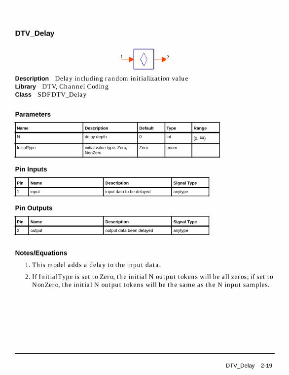
DTV_Delay
Description Delay including random initialization valueLibrary DTV, Channel CodingClass SDFDTV_Delay
Parameters
Pin Inputs
Pin Outputs
Notes/Equations
1. This model adds a delay to the input data.
2. If InitialType is set to Zero, the initial N output tokens will be all zeros; if set toNonZero, the initial N output tokens will be the same as the N input samples.
Name Description Default Type Range
N delay depth 0 int [0, ∞)
InitialType initial value type: Zero,NonZero
Zero enum
Pin Name Description Signal Type
1 input input data to be delayed anytype
Pin Name Description Signal Type
2 output output data been delayed anytype
DTV_Delay 2-19

Channel Coding Components
DTV_Demapper
Description Soft demapper for uniform and non-uniform QPSK, 16QAM and 64QAMLibrary DTV, Channel CodingClass SDFDTV_Demapper
Parameters
Pin Inputs
Pin Outputs
Notes/Equations
1. This model de-maps uniform and non-uniform QPSK, 16QAM, and 64QAM todetermine the soft-bit information that is used by Viterbi decoding.
Each firing, the CSI and input pins consume 1 token each; 2 tokens for QPSK, 4tokens for 16QAM, or 6 tokens for 64QAM are generated.
Name Description Default Type Range
MappingMode signal constellations andmapping: QPSK, QAM-16,QAM-64
QAM-16 enum
Alpha non-uniform factor forDVB-T.
1 int [1, ∞)
Pin Name Description Signal Type
1 input signal to be demodulated complex
2 CSI channel state information real
Pin Name Description Signal Type
3 output soft metric information real
2-20 DTV_Demapper

2. MappingMode specifies the signal constellation and mapping mode: QPSK,QAM-16 or QAM-64.
While the constellation point is sent to the input port before demapping, thepoint is scaled up by a factor that is determined by Alpha and MappingModegiven in Table 2-4.
3. The soft bits are determined by the decision equations.
I is the real part of product and Q is the imaginary part.
• 64QAM decision equations are:
b0 = Ib1 = Qb2 = 4 - |b0|b3 = 4 - |b1|b4 = 2 - |b2|b5 = 2 - |b3|
• 16QAM decision equations are:
b0 = Ib1 = Qb2 = 2 - |b0|b3 = 2 - |b1|
• QPSK decision equations are:
Table 2-4. De-Normalization Factors for Data Symbols
Modulation Scheme Normalization Factor
QPSK
16-QAM: Alpha=1
16-QAM: Alpha=2
16-QAM: Alpha=4
64-QAM: Alpha=1
64-QAM: Alpha=2
64-QAM: Alpha=4
c z 2( )×=
c z 10( )×=
c z 20( )×=
c z 52( )×=
c z 42( )×=
c z 60( )×=
c z 108( )×=
DTV_Demapper 2-21

Channel Coding Components
b0 = Ib1 = Q
The final soft bit information b is the product of soft bits calculated by the aboveequations and the CSI input.
References
[1]ETSI, Digital Video Broadcasting (DVB); Framing structure, channel codingand modulation for digital terrestrial television. EN300 744 v1.2.1, EuropeanTelecommunication Standard, July 1999.
[2] M. R. G. Butler, S. Armour, P.N. Fletcher, A.R. Nix, D.R. Bull, “Viterbi DecodingStrategies for 5 GHz Wireless LAN Systems” Vehicular Technology Conference,2001. VTC 2001 Fall. IEEE VTS 54th, Volume: 1, 2001.
2-22 DTV_Demapper

DTV_DQPSKCoder
Description DQPSK baseband modulatorLibrary DTV, Channel CodingClass SDFDTV_DQPSKCoder
Parameters
Pin Inputs
Pin Outputs
Notes/Equations
1. This model performs π/4 shift DQPSK constellation mapping and modulation.
Each firing, two bits of input data are consumed to produce the complex dataoutput.
2. Phase calculation and mapping is shown in Figure 2-6.
Complex data is calculated by
Name Description Default Type Range
Delay delay of feedback (aslength of register)
384 int [1, ∞)
Pin Name Description Signal Type
1 input input data bits int
Pin Name Description Signal Type
2 output signal after constellation mapping complex
I jQ j
θ jcos θ jsin–
θ jsin θ jcos
I j 1–Q j 1–
=
DTV_DQPSKCoder 2-23

Channel Coding Components
where (Ij, Qj) denotes complex data of the jth symbol and d denotes the numberof symbols between (Ij, Qj) and (Ij-1, Qj-1).
Figure 2-6. Phase Calculation and π/4 Shift DQPSK Constellation Mapping
References
[1]ARIB-JAPAN, Terrestrial Integrated Services Digital Broadcasting (ISDB-T);Specification of Channel Coding, Framing Structure and Modulation,Sept.1998.
Q Channel
I Channel2
2
+1
+1 +
2+
2+ -1
-1
Inputb0′, b1′
Outputθ j
0, 0
0, 1
1, 0
1, 1
π / 4
− π / 4
3 π / 4
−3 π / 4
2-24 DTV_DQPSKCoder

DTV_DQPSKDecoder
Description DQPSK decoder with soft decisionLibrary DTV, Channel CodingClass SDFDTV_DQPSKDecoder
Parameters
Pin Inputs
Pin Outputs
Notes/Equations
1. This model performs π/4 shift DQPSK demodulation; it is the reverse of theprocess for DTV_DQPSKCoder.
It decodes the complex DQPSK signal to floating-point data to be Viterbiconvolutional decoded.
Name Description Default Type Range
Delay delay of feedback (aslength of register)
384 int [1, ∞)
Renorm option to re-normalizereference phase (set to thenearest symbol point): NO, YES
NO enum
Pin Name Description Signal Type
1 input signal to be demodulated complex
Pin Name Description Signal Type
2 output signal after demodulation real
DTV_DQPSKDecoder 2-25

Channel Coding Components
References
[1]ARIB-JAPAN, Terrestrial Integrated Services Digital Broadcasting (ISDB-T);Specification of Channel Coding, Framing Structure and Modulation,Sept.1998.
2-26 DTV_DQPSKDecoder

DTV_InnerDecoder
Description Punctured convolutional decoderLibrary DTV, Channel Coding
Parameters
Pin Inputs
Pin Outputs
Notes/Equations
1. This subnetwork model performs punctured convolutional decoding over theinput signal.
The schematic for this subnetwork is shown in Figure 2-7.
Name Description Default Type Range
PuncConvType punctured convolutionalcode type: DTV_1_2,DTV_2_3, DTV_3_4,DTV_5_6, DTV_7_8
DTV_1_2 enum
TrunLen path memory truncationlength (bytes)
10 int [5, ∞)
DelayByte number of bytes to delayfor delay adjustment
0 int [-∞, 204 -TrunLen]
Pin Name Description Signal Type
1 input signal to be decoded real
Pin Name Description Signal Type
2 output decoded signal int
DTV_InnerDecoder 2-27

Channel Coding Components
Figure 2-7. DTV_InnerDecoder Schematic
2. At the receiver side, DTV_PuncDecoder calculates the puncturing pattern andinserts null (zero) at the position where a bit is punctured. A Viterbi decoder isthen used to further decode the recovered code bit stream. By replacing thepunctured bits with nulls, the punctured bits do not contribute to decodingperformance.
The data rate of the mother convolutional code is 1/2.
3. The generator polynomial is G1=171oct and G2=133oct.
References
[1]ETSI, Digital Video Broadcasting (DVB); Framing structure, channel codingand modulation for digital terrestrial television. EN300 744 v1.2.1, EuropeanTelecommunication Standard, July 1999.
2-28 DTV_InnerDecoder

DTV_InterlvFloat
Description Interleaver and de-interleaver for floatLibrary DTV, Channel CodingClass SDFDTV_InterlvFloat
Parameters
Pin Inputs
Pin Outputs
Notes/Equations
1. This model performs floating-point symbol interleaving or de-interleaving overthe input signal. It performs de-interleaving of the floating-point symbol afterQAM, QPSK or DQPSK decoding.
A general interleaver is used for floating-point data. It is composed of a numberof FIFO delay branches as specified by the Delays array in which the delay can
Name Description Default Type Range
Delays delay of each branch 0 1 2 3 int array [0, ∞)
Initial_value initial value in interleaverdelay FIFOs
0.0 real [0, ∞)
Multiplier multiple branch number 1 int [1, ∞)
Pin Name Description Signal Type
1 input signal to be interleaved real
Pin Name Description Signal Type
2 output interleaved signal real
DTV_InterlvFloat 2-29

Channel Coding Components
be specified individually. Multiplier can be used to implement multipleisomorphic interleavers.
The structure of this interleaver is the same as that of DTV_InterlvInt, exceptthis model handles floating-point data.
References
[1]ARIB-JAPAN, Terrestrial Integrated Services Digital Broadcasting (ISDB-T);Specification of Channel Coding, Framing Structure and Modulation,Sept.1998.
[2] ETSI, Digital Video Broadcasting (DVB); Framing structure, channel codingand modulation for digital terrestrial television. EN300 744 v1.2.1, EuropeanTelecommunication Standard, July 1999.
2-30 DTV_InterlvFloat

DTV_InterlvInt
Description Interleaver and de-interleaver for integerLibrary DTV, Channel CodingClass SDFDTV_InterlvInt
Parameters
Pin Inputs
Pin Outputs
Notes/Equations
1. This model performs interleaving or de-interleaving over the input signal.
A general interleaver is used for integer data. It is composed of a number ofFIFO delay branches as specified by the Delays array in which the delay can be
Name Description Default Type Range
Delays delay of each branch 0 1 2 int array [0, ∞)
Initial_value initial value in interleaverdelay FIFOs
0 int [0, ∞)
Multiplier multiple branch number 1 int [1, ∞)
InitialType interleaver delay FIFOsinitial value type: Const,Random
Const enum
Pin Name Description Signal Type
1 input signal to be interleaved int
Pin Name Description Signal Type
2 output interleaved signal int
DTV_InterlvInt 2-31

Channel Coding Components
specified individually. Multiplier can be used to implement multiple isomorphicinterleavers.
The InitialType parameter specifies the initialization values for the interleaverbuffers. Table 2-5 shows the relationships of InitialType, Initial_value, andinitial buffer values.
2. The conceptual structure of the interleaver used in ISDB-T is described here.
Following the conceptual scheme in Figure 2-8, convolutional byte-wiseinterleaving with length of I=12 is applied to the 204-byte packets. Forsynchronization, the bytes following SYNC bytes will be routed in branch 0 ofthe interleaver (corresponding to a null delay).
The interleaver can be composed of I=12 branches, cyclically connected to theinput byte-stream by the input switch. Each branch j must be a first-in, first-out(FIFO) shift register, with length of j×17 bytes. The cells of the FIFO mustcontain 1 byte, and the input and output switches must be synchronized.
The de-interleaver, in principle, is the same as the interleaver, but the branchindices are reversed.
I corresponds to the size of Delay array. The size of every branch, (j×17 inFigure 2-8), corresponds to the element of Delay array. Multiplier is the numberof FIFO register in the interleaver, its value is 1 in Figure 2-8.
The conceptual interleaver structure with Multiplier = N and Delay array = (0,1×K, 2×K, ... , (I-1)×K) is shown in Figure 2-9.
Table 2-5. Initial Buffer Values
InitialType Initial_value Initial Buffer Value
Const i (integer) i
Random 1<=i<=32 i-bit random integer
i<=0 or i>32 8-bit random integer
2-32 DTV_InterlvInt

Figure 2-8. ISDB-T Interleaver
Figure 2-9. Interleaver with Multiplier=N andDelay Array= (0, 1×K, 2×K, ... , (I-1)×K)
References
[1]ARIB-JAPAN, Terrestrial Integrated Services Digital Broadcasting (ISDB-T);Specification of Channel Coding, Framing Structure and Modulation,Sept.1998.
[2] ETSI, Digital Video Broadcasting (DVB); Framing structure, channel codingand modulation for digital terrestrial television. EN300 744 v1.2.1, EuropeanTelecommunication Standard, July 1999.
17x2 bytes
17x3 bytes
17 bytes
0
1
2
3
17x11 bytes11
FIFO shift register
1 byte per position
2×k bytes
k bytes
0
1
2
(I-1) × k bytesI - 1
1 byte per position
k bytesI + 1
I
(I-1) × k bytes2×I-1
(N-1)×1
(N-1)× I+1k bytes
(I-1) × k bytesN×I-1
DTV_InterlvInt 2-33

Channel Coding Components
DTV_ISDBChCoder
Description Channel coder of ISDB-TLibrary DTV, Channel Coding
Parameters
Pin Inputs
Pin Outputs
Notes/Equations
1. This subnetwork model performs channel coding except RS-coding in anISDB-T signal generator. Functions include bit-wise randomization (energydispersal), delay adjustment for byte-wise interleaving and deinterleaving, andpunctured convolutional encoding.
The schematic for this subnetwork is shown in Figure 2-10.
Name Description Default Type Range
Mode transmission mode: Mode1, Mode 2, Mode 3
Mode 1 enum
MappingMode signal constellations andmapping: DQPSK, QPSK,QAM-16, QAM-64
DQPSK enum
CodeRate convolutional code rate:DTV 1/2, DTV 2/3, DTV3/4, DTV 5/6, DTV 7/8
DTV 1/2 enum
Segments number of segments perlayer
13 int [1, 13]
Pin Name Description Signal Type
1 In input data int
Pin Name Description Signal Type
2 Out output int
2-34 DTV_ISDBChCoder

Figure 2-10. DTV_ISDBChCoder Schematic
2. Input of the subnetwork starts with the synchronization byte of the first frame.
3. DTV_ISDBRandomize randomizes RS-coded bytes with a block size of 204bytes.
4. DTV_Delay, with DTV_InterlvInt, adjusts the delay between the transmitterand the receiver to provide an identical transmission and reception delay of oneframe length for all hierarchical layers. The number of bytes to be delayed ineach hierarchical layer is:
Delay = (MapRate × 96Mode × CodeRate)/8 − 204 × 11
where
MapRate equals 2, 2, 4, or 6 for DQPSK, QPSK, 16QAM, or 64QAM,respectively
Mode equals 0, 1, or 2 for Mode 1, Mode 2, or Mode 3, respectively
CodeRate represents the inner code rate 1/2, 2/3, 3/4, 5/6, or 7/8
204 × 11 is the delay derived from byte interleaver and deinterleaver.
References
[1]ARIB STD-B31 Version 1.5, Transmission System for Digital TerrestrialTelevision Broadcasting, July 29, 2003.
DTV_ISDBChCoder 2-35

Channel Coding Components
DTV_ISDBChDecoder
Description Channel decoder of ISDB-TLibrary DTV, Channel Coding
Parameters
Pin Inputs
Pin Outputs
Notes/Equations
1. This subnetwork model performs convolutional decoding, delay adjustment,byte-wise deinterleaving, and energy distribution.
The schematic for this subnetwork is shown in Figure 2-11.
Name Description Default Type Range
Mode transmission mode: Mode1, Mode 2, Mode 3
Mode 1 enum
MappingMode signal constellations andmapping: DQPSK, QPSK,QAM-16, QAM-64
DQPSK enum
CodeRate convolutional code rate:DTV 1/2, DTV 2/3, DTV3/4, DTV 5/6, DTV 7/8
DTV 1/2 enum
Segments number of segments perlayer
13 int [1, 13]
TrunLen path memory truncationlength (bytes)
10 int [5, ∞)
DelayByte number of bytes to delayfor delay adjustment
8 int [0, ∞)
Pin Name Description Signal Type
1 In input data real
Pin Name Description Signal Type
2 Out output int
2-36 DTV_ISDBChDecoder

Figure 2-11. DTV_ISDBChDecoder Schematic
2. The DelayByte parameter includes all delay bytes before and afterconvolutional decoding.
3. The Delay component adjusts the block size to 204 bytes after convolutionaldecoding.
References
[1]ARIB STD-B31 Version 1.5, Transmission System for Digital TerrestrialTelevision Broadcasting, July 29, 2003.
DTV_ISDBChDecoder 2-37

Channel Coding Components
DTV_ISDBDerandomize
Description ISDB-T energy derandomization of tansmission stream packagesLibrary DTV, Channel Coding
Parameters
Pin Inputs
Pin Outputs
Notes/Equations
1. This subnetwork model derandomizes the signal after byte deinterleaving.
The schematic for this subnetwork is shown in Figure 2-12.
Name Description Default Type Range
Mode transmission mode: Mode1, Mode 2, Mode 3
Mode 1 enum
CodeRate convolutional code rate:DTV 1/2, DTV 2/3, DTV3/4, DTV 5/6, DTV 7/8
DTV 1/2 enum
MappingMode signal constellations andmapping: DQPSK, QPSK,QAM-16, QAM-64
DQPSK enum
Segments number of segments perlayer
13 int [1, 13]
Delay equivalent delay in bitsbetween randomizer andde-randomizer
0 int [0, ∞)
Pin Name Description Signal Type
1 In input int
Pin Name Description Signal Type
2 Out output int
2-38 DTV_ISDBDerandomize

Figure 2-12. DTV_ISDBDerandomize Schematic
2. Derandomization is conducted using a PRBS shown in Figure 2-13.
G(x)=x15+x14+1
Figure 2-13. PRBS Generating Polynomial and Circuit
3. All signals except the synchronization bytes in each TSP are XORed bit-by-bitusing PRBSs, MSB (most significant bit) first. The PRBS-generator isinitialized at the beginning of each OFDM frame with 100101010000000 (D1,D2, ... , D15 in Figure 2-13). In each frame, the first PRBS bit is applied to theMSB of the byte next to the TSP synchronization byte (the second byte of theframe). Note that the shift register also performs shifting when the TSPsynchronization byte arrives.
4. The Delay parameter includes all delay bits before derandomization.
References
[1]ARIB STD-B31 Version 1.5, Transmission System for Digital TerrestrialTelevision Broadcasting, July 29, 2003.
1 0 0 1 0 1 0 1 0 0 0
Initia lization Sequence
D D D D D D D D D D D
1 2 3 4 5 6 7 8 9 10 11
0 0 0
D D D
12 13 14
0
D
15
+
Output
DTV_ISDBDerandomize 2-39

Channel Coding Components
DTV_ISDBRandomize
Description ISDB-T energy randomization of tansmission stream packagesLibrary DTV, Channel Coding
Parameters
Pin Inputs
Pin Outputs
Notes/Equations
1. This subnetwork model randomizes the RS-coded TSP with a block size of 204bytes in an ISDB-T signal generator. (This subnetwork can also be referred toas an energy-disperser.)
The schematic for the subnetwork is shown in Figure 2-14.
Name Description Default Type Range
Mode transmission mode: Mode1, Mode 2, Mode 3
Mode 1 enum
CodeRate convolutional code rate:DTV 1/2, DTV 2/3, DTV3/4, DTV 5/6, DTV 7/8
DTV 1/2 enum
MappingMode signal constellations andmapping: DQPSK, QPSK,QAM-16, QAM-64
DQPSK enum
Segments number of segments perlayer
13 int [1, 13]
Pin Name Description Signal Type
1 In input int
Pin Name Description Signal Type
2 Out output int
2-40 DTV_ISDBRandomize

Figure 2-14. DTV_ISDBRandomize Schematic
2. Randomization is conducted at each hierarchical layer using a PRBS as shownin Figure 2-15.
G(x)=x15+x14+1
Figure 2-15. PRBS Generating Polynomial and Circuit
3. All signals except the synchronization bytes in each TSP are XORed bit-by-bitusing PRBSs, most significant bit first.
4. The PRBS generator is initialized at the beginning of each OFDM frame withthe sequence of 100101010000000 (D1, D2, ... , D15 in Figure 2-15). In eachframe, the PRBS first bit is applied to the most significant bit of the byte next tothe TSP synchronization byte (the second byte of the frame).
The shift register will also perform shifting when the TSP synchronization bytearrives.
1 0 0 1 0 1 0 1 0 0 0
Initia lization Sequence
D D D D D D D D D D D
1 2 3 4 5 6 7 8 9 10 11
0 0 0
D D D
12 13 14
0
D
15
+
Output
DTV_ISDBRandomize 2-41

Channel Coding Components
5. Input of the subnetwork starts with the synchronization byte of the first frame.
References
[1]ARIB STD-B31 Version 1.5, Transmission System for Digital TerrestrialTelevision Broadcasting, July 29, 2003.
2-42 DTV_ISDBRandomize

DTV_Mapper
Description Uniform and non-uniform mapping for DVB-T and ISDB-TLibrary DTV, Channel CodingClass SDFDTV_Mapper
Parameters
Pin Inputs
Pin Outputs
Notes/Equations
1. This model performs QPSK, 16QAM, 64QAM mapping or non-uniform 16QAMand 64QAM Gray mapping.
Each firing, 2 tokens for QPSK, 4 tokens for 16QAM, or 6 tokens for 64QAM areconsumed and one constellation symbol is generated.
2. The MappingMode parameter specifies the constellation and mapping mode:QPSK, QAM-16 or QAM-64.
3. The Alpha parameter determines the exact proportions of the constellation.Alpha is the minimum distance separating the two constellation points carrying
Name Description Default Type Range
MappingMode signal constellations andmapping: QPSK, QAM-16,QAM-64
QAM-16 enum
Alpha non-uniform factor forDVB-T.
1 int [1, ∞)
Pin Name Description Signal Type
1 input input data bits int
Pin Name Description Signal Type
2 output signal after constellation mapping complex
DTV_Mapper 2-43

Channel Coding Components
different high-priority bit values divided by the minimum distance separatingany two constellation points. While the non-hierarchical transmission uses thesame uniform constellation as Alpha=1, non-uniform constellation forhierarchical transmission is also supported using Alpha=2 or 4.
4. Bit patterns based on Alpha and MappingMode settings are shown inFigure 2-16 through Figure 2-21.
Figure 2-16. QPSK, 16-QAM Mapping Bit Patterns(Non-Hierarchical and Hierarchical, Alpha=1)
10 00
0111
1
-1
1-1Rez Convey y0,q′
Imz Convey y1,q′
1010 00103
-3
1-1Rez Convey y0,q′, y2,q′
Imz Convey y1,q′, y3,q′
1000
-3 3
0000
1011 00111
1001 0001
1111 0111-1
1101 0101
1110 01101100 0100
QPSKBit Order:y0,q′, y1,q′
16-QAMBit Order:y0,q′, y1,q′,y2,q′, y3,q′
2-44 DTV_Mapper

Figure 2-17. 64-QAM Mapping Bit Patterns(Non-Hierarchical and Hierarchical, Alpha=1)
Figure 2-18. Non-Uniform 16-QAM Mapping Bit Patterns (Alpha=2)
101001
7
-3
-1Rez Convey y0,q′, y2,q′, y4,q′
Imz Convey y1,q′, y3,q′, y5,q′
101011
-3
1
-1
64-QAMBit Order:y0,q′, y1,q′,y2,q′, y3,q′, y4,q′, y5,q′
100011100001
101000101010100010100000
101100101110100110100100
101101101111100111100101
5
3
000001000011001011001001
000000000010001010001000
000100000110001110001100
000101000111001111001101
-5-7 7531
111101111111110111110101
111100111110110110110100
111000111010110010110000
111001111011110011110001
010101010111011111011101
010100010110011110011100
010000010010011010011000
010001010011011011011001-5
-7
1010 00104
-4
2-2Rez Convey y0,q′, y2,q′
Imz Convey y1,q′, y3,q′
1000
-4 4
0000
1011 00112
1001 0001
1111 0111-2
1101 0101
1110 01101100 0100
Non-Uniform16-QAMBit Order:y0,q′, y1,q′,y2,q′, y3,q′
DTV_Mapper 2-45

Channel Coding Components
Figure 2-19. Non-Uniform 64-QAM Mapping Bit Patterns (Alpha=2)
Figure 2-20. Non-Uniform 16-QAM Mapping Bit Patterns (Alpha=4)
101001
8
-4
-2Rez Convey y0,q′, y2,q′, y4,q′
Imz Convey y1,q′, y3,q′, y5,q′
101011
-4
2
-2
Non-Uniform 64-QAMBit Order:y0,q′, y1,q′,y2,q′, y3,q′, y4,q′, y5,q′
100011100001
101000101010100010100000
101100101110100110100100
101101101111100111100101
6
4
000001000011001011001001
000000000010001010001000
000100000110001110001100
000101000111001111001101
-6-8 8642
111101111111110111110101
111100111110110110110100
111000111010110010110000
111001111011110011110001
010101010111011111011101
010100010110011110011100
010000010010011010011000
010001010011011011011001-6
-8
1010 00106
-6
4-4Rez Convey y0,q′, y2,q′
Imz Convey y1,q′, y3,q′
1000
-6 6
0000
1011 00114
1001 0001
1111 0111-4
1101 0101
1110 01101100 0100
Non-Uniform16-QAMBit Order:y0,q′, y1,q′,y2,q′, y3,q′
2-46 DTV_Mapper

Figure 2-21. Non-Uniform 64-QAM Mapping Bit Patterns (Alpha=4)
5. The mapped symbols are normalized; normalization factors are shown inTable 2-6.
References
Table 2-6. Normalization Factors
Modulation Scheme Normalization Factor
QPSK
16-QAMAlpha=1
16-QAMAlpha=2
16-QAMAlpha=4
64-QAMAlpha=1
64-QAMAlpha=2
64-QAMAlpha=4
101001
10
-6
-4Rez Convey y0,q′, y2,q′, y4,q′
Imz Convey y1,q′, y3,q′, y5,q′
101011
-6
4
-4
Non-Uniform 64-QAMBit Order:y0,q′, y1,q′,y2,q′, y3,q′, y4,q′, y5,q
100011100001
101000101010100010100000
101100101110100110100100
101101101111100111100101
8
6
000001000011001011001001
000000000010001010001000
001100000110001110001100
000101000111001111001101
-8-10 10864
111101111111110111110101
111100111110110110110100
111000111010110010110000
111001111011110011110001
010101010111011111011101
010100010110011110011100
010000010010011010011000
010001010011011011011001-8
-10
c z 2( )⁄=
c z 10( )⁄=
c z 20( )⁄=
c z 52( )⁄=
c z 42( )⁄=
c z 60( )⁄=
c z 108( )⁄=
DTV_Mapper 2-47

Channel Coding Components
[1]ETSI, Digital Video Broadcasting (DVB); Framing structure, channel codingand modulation for digital terrestrial television. EN300 744 v1.2.1, EuropeanTelecommunication Standard, July 1999.
2-48 DTV_Mapper

DTV_PNreset
Description PN code source with reset inputLibrary DTV, Channel CodingClass SDFDTV_PNreset
Parameters
Pin Inputs
Pin Outputs
Notes/Equations
1. This model generates a pseudo-random binary sequence with less than 32internal shift registers and an external reset pin.
Name Description Default Type Range
Polynomial generator polynomial(X^0+X^1+...+X^M)
1 0 0 0 0 0 0 0 0 00 0 0 0 1 1
int array [0, 1]
Initial initial and reset value inregisters
1 0 0 1 0 1 0 1 0 00 0 0 0 0
int array [0, 1]
SignalPoint output register after eachshift
0 int [0, 31]
Pin Name Description Signal Type
1 reset reset pulse int
Pin Name Description Signal Type
2 output pseudo random binary sequence int
DTV_PNreset 2-49

Channel Coding Components
2. This model generates pseudo-random binary sequence for energy dispersal ofthe TSPs. In the ISDB-T specification, the polynomial for this pseudo-randombinary sequence generator is:
g(x) = x15 + x14 + 1
At the start of every OFDM frame, the reset signal becomes valid while theinternal shift register is initialized to the sequence of 100101010000000. PRBSgeneration is shown in Figure 2-22.
Figure 2-22. PRBS Generation
References
[1]ARIB-JAPAN, Terrestrial Integrated Services Digital Broadcasting (ISDB-T);Specification of Channel Coding, Framing Structure and Modulation,Sept.1998.
[2] ETSI, Digital Video Broadcasting (DVB); Framing structure, channel codingand modulation for digital terrestrial television. EN300 744 v1.2.1, EuropeanTelecommunication Standard, July 1999.
1 0 0 1 0 1 0 1 0 0 0
Initia lization sequence
D D D D D D D D D D D
1 2 3 4 5 6 7 8 9 10 11
0 0 0
D D D
12 13 14
0
D
15
+
Output
2-50 DTV_PNreset

DTV_PuncCoder
Description Puncture coderLibrary DTV, Channel CodingClass SDFDTV_PuncCoder
Parameters
Pin Inputs
Pin Outputs
Notes/Equations
1. This model perforates the input convolutional code to produce a puncturedconvolutional code. Each firing, K tokens are consumed and N tokens areproduced; K and N are determined based on code type; refer to Table 2-7.
2. Punctured convolutional code is usually generated by perforate a motherconvolutional code according to a certain pattern to achieve a different datarate. This model determines the perforation pattern according to the code type
Name Description Default Type
PuncConvType punctured convolutionalcode type: DTV 1/2, DTV2/3, DTV 3/4, DTV 5/6,DTV 7/8
DTV 1/2 enum
Pin Name Description Signal Type
1 input input signal to be perforated anytype
Pin Name Description Signal Type
2 output output signal after perforated anytype
DTV_PuncCoder 2-51

Channel Coding Components
chosen, then reads the input convolutional coded bits and outputs the input bitor discards it according to the pattern in Table 2-8.
References
[1]ARIB-JAPAN, Terrestrial Integrated Services Digital Broadcasting (ISDB-T);Specification of Channel Coding, Framing Structure and Modulation,Sept.1998.
[2] ETSI, Digital Video Broadcasting (DVB); Framing structure, channel codingand modulation for digital terrestrial television. EN300 744 v1.2.1, EuropeanTelecommunication Standard, July 1999.
Table 2-7. K and N Values
PuncConvType
K(No. ofInput Bytes)
N(No. ofOutput Bits)
DTV 1/2 2 2
DTV 2/3 4 3
DTV 3/4 6 4
DTV 5/6 10 6
DTV 7/8 14 8
Table 2-8. Puncture Pattern and Transmit Sequence
PuncConvTypePuncturePattern
TransmitSequence
DTV 1/2 2 2
DTV 2/3 4 3
DTV 3/4 6 4
DTV 5/6 10 6
DTV 7/8 14 8
2-52 DTV_PuncCoder

DTV_PuncConvCoder
Description Punctured convolutional encoderLibrary DTV, Channel Coding
Parameters
Pin Inputs
Pin Outputs
Notes/Equations
1. This subnetwork model performs punctured convolutional encoding.
The schematic for this subnetwork is shown in Figure 2-23.
Figure 2-23. DTV_PuncConvCoder Schematic
Name Description Default Type
PuncConvType punctured convolutionalcode type: DTV_1_2,DTV_2_3, DTV_3_4,DTV_5_6, DTV_7_8
DTV_1_2 enum
Pin Name Description Signal Type
1 input signal to be encoded int
Pin Name Description Signal Type
2 output encoded signal int
DTV_PuncConvCoder 2-53

Channel Coding Components
2. This subnetwork converts byte input data into bit streams and uses a generalconvolutional coding model to encode them into the mother convolutional codeof data rate 1/2.
A puncture encoder generates the punctured convolutional code. PuncConvTypespecifies the type of DTV punctured convolutional code.
The encoder is shown in Figure 2-24.
Figure 2-24. Mother Convolutional Code of Rate 1/2(Constraint Length=7)
References
[1]ETSI, Digital Video Broadcasting (DVB); Framing structure, channel codingand modulation for digital terrestrial television. EN300 744 v1.2.1, EuropeanTelecommunication Standard, July 1999.
1-bitDelay
1-bitDelay
1-bitDelay
1-bitDelay
1-bitDelay
1-bitDelay
DataInput
Y Output, G2 = 133oct
X Output, G1 = 171oct
2-54 DTV_PuncConvCoder

DTV_PuncConvDecoder
Description Punctured convolutional decoderLibrary DTV, Channel Coding
Parameters
Pin Inputs
Pin Outputs
Name Description Default Type Range
PuncConvType punctured convolutionalcode type: DTV_1_2,DTV_2_3, DTV_3_4,DTV_5_6, DTV_7_8
DTV_1_2 enum
NumBits number of soft decision bits 4 int [1, ∞)
SymbolLen path memory truncationlength
8 int [1, ∞)
DelayBit number of bits to delay fordelay adjustment
0 int [0, ∞)†
DelayByte number of bytes to delayfor delay adjustment
0 int [-∞, 204 -SymbolLen]
DelayCC number of bits to delaybefore Viterbi decoder
0 int [0, ∞)††
† In ISDB and DVB, DelayBit=0†† In ISDB and DVB, DelayCC=0
Pin Name Description Signal Type
1 input signal to be decoded int
Pin Name Description Signal Type
2 output decoded signal int
DTV_PuncConvDecoder 2-55

Channel Coding Components
Notes/Equations
1. This subnetwork model performs punctured convolutional decoding of data rate1/2 over the input signal. The schematic for this subnetwork is shown inFigure 2-25.
Figure 2-25. DTV_PuncConvDecoder Schematic
2. A puncture decoder model is used to decode the punctured convolutionalencoded input to normal convolutional coded data. A general Viterbiconvolutional decoding model is used to further decode it. After decoding, bitdelay adjustment is performed, bits are packed to bytes and, if necessary, a bytedelay adjustment is applied before output.
The data rate of the mother convolutional code is 1/2.
The encoder is shown in Figure 2-26.
Figure 2-26. Mother Convolutional Code of Rate 1/2(Constraint Length=7)
References
[1]ARIB-JAPAN, Terrestrial Integrated Services Digital Broadcasting (ISDB-T);Specification of Channel Coding, Framing Structure and Modulation,Sept.1998.
1-bitDelay
1-bitDelay
1-bitDelay
1-bitDelay
1-bitDelay
1-bitDelay
DataInput
Y Output, G2 = 133oct
X Output, G1 = 171oct
2-56 DTV_PuncConvDecoder

[2] ETSI, Digital Video Broadcasting (DVB); Framing structure, channel codingand modulation for digital terrestrial television. EN300 744 v1.2.1, EuropeanTelecommunication Standard, July 1999.
DTV_PuncConvDecoder 2-57

Channel Coding Components
DTV_PuncDecoder
Description Puncture decoderLibrary DTV, Channel CodingClass SDFDTV_PuncDecoder
Parameters
Pin Inputs
Pin Outputs
Notes/Equations
1. This model completes the inverse procedure of the puncture coder that wasperforated during puncture encoding. Each firing, K tokens are consumed at theinput and N tokens are produced according to Table 2-9.
2. This model interpolates a zero value to the punctured data stream to form afull-length data stream. The perforation pattern, based on PuncConvType, then
Name Description Default Type
PuncConvType Punctured convolutionalcode type: DTV 1/2, DTV2/3, DTV 3/4, DTV 5/6,DTV 7/8
DTV 1/2 enum
Pin Name Description Signal Type
1 input input signal to be refilled real
Pin Name Description Signal Type
2 output output signal after refilled real
2-58 DTV_PuncDecoder

interpolates zero into the input bits to form the output according to the patternin Table 2-10.
References
[1]ARIB-JAPAN, Terrestrial Integrated Services Digital Broadcasting (ISDB-T);Specification of Channel Coding, Framing Structure and Modulation,Sept.1998.
[2] ETSI, Digital Video Broadcasting (DVB); Framing structure, channel codingand modulation for digital terrestrial television. EN300 744 v1.2.1, EuropeanTelecommunication Standard, July 1999.
Table 2-9. K and N Values
PuncConvType K N
DTV 1/2 2 2
DTV 2/3 4 3
DTV 3/4 6 4
DTV 5/6 10 6
DTV 7/8 14 8
Table 2-10. Puncture Pattern and Transmit Sequence
PuncConvTypePuncturePattern
TransmitSequence
DTV 1/2 2 2
DTV 2/3 4 3
DTV 3/4 6 4
DTV 5/6 10 6
DTV 7/8 14 8
DTV_PuncDecoder 2-59

Channel Coding Components
DTV_QAM16Coder
Description Uniform and non-uniform 16-QAM encoder for DVB-T and ISDB-TLibrary DTV, Channel CodingClass SDFDTV_QAM16Coder
Parameters
Pin Inputs
Pin Outputs
Notes/Equations
1. This model performs 16-QAM mapping and non-uniform 16-QAM Graymapping.
2. This model groups the input data bits to 4-bit groups and maps them into acomplex signal from the 16-QAM constellation (shown in Figure 2-27), or maps
Name Description Default Type Range
Alpha non-uniform factor forDVB-T.
1 int [1, ∞)
Pin Name Description Signal Type
1 input input data bits int
Pin Name Description Signal Type
2 output signal after constellation mapping complex
2-60 DTV_QAM16Coder

them into a complex signal from the non-uniform 16-QAM constellation, (shownin Figure 2-28 and Figure 2-29).
Figure 2-27. Uniform and Non-Uniform 16-QAM with Alpha = 1Mapping and Corresponding Bit Pattern
Figure 2-28. Non-Uniform 16-QAM with Alpha = 2Mapping and Corresponding Bit Pattern
1010 00103
-3
1-1Rez Convey y0,q′, y2,q′
Imz Convey y1,q′, y3,q′
1000
-3 3
0000
1011 00111
1001 0001
1111 0111-1
1101 0101
1110 01101100 0100
Bit Order:y0,q′, y1,q′,y2,q′, y3,q′
1010 00104
-4
2-2Rez Convey y0,q′, y2,q′
Imz Convey y1,q′, y3,q′
1000
-4 4
0000
1011 00112
1001 0001
1111 0111-2
1101 0101
1110 01101100 0100
Bit Order:y0,q′, y1,q′,y2,q′, y3,q′
DTV_QAM16Coder 2-61

Channel Coding Components
Figure 2-29. Non-Uniform 16-QAM with Alpha = 4Mapping and Corresponding Bit Pattern
After mapping, the output signal is normalized by a normalization factor c, thevalue of c is:
where z is the complex signal from 16-QAM and non-uniform 16-QAMconstellation.
References
[1]ARIB-JAPAN, Terrestrial Integrated Services Digital Broadcasting (ISDB-T);Specification of Channel Coding, Framing Structure and Modulation,Sept.1998.
[2] ETSI, Digital Video Broadcasting (DVB); Framing structure, channel codingand modulation for digital terrestrial television. EN300 744 v1.2.1, EuropeanTelecommunication Standard, July 1999.
1010 00106
-6
4-4Rez Convey y0,q′, y2,q′
Imz Convey y1,q′, y3,q′
1000
-6 6
0000
1011 00114
1001 0001
1111 0111-4
1101 0101
1110 01101100 0100
Bit Order:y0,q′, y1,q′,y2,q′, y3,q′
c z10
----------= α, 1=
c z20
----------= α, 2=
c z52
----------= α, 4=
2-62 DTV_QAM16Coder

DTV_QAM16Decoder
Description Uniform and non-uniform 16-QAM decoder for DVB-T and ISDB-TLibrary DTV, Channel CodingClass SDFDTV_QAM16Decoder
Parameters
Pin Inputs
Pin Outputs
Notes/Equations
1. This model performs 16-QAM de-mapping and non-uniform 16-QAM Grayde-mapping; it is the reverse of the process for DTV_QAM16Coder.
Name Description Default Type Range
Alpha non-uniform factor forDVB-T.
1 int [1, ∞)
Pin Name Description Signal Type
1 input signal to be demodulated complex
Pin Name Description Signal Type
2 output signal after demodulation real
DTV_QAM16Decoder 2-63

Channel Coding Components
2. This model de-maps the input complex QAM signal data to floating-point datafor Viterbi convolutional decoding according to 16-QAM or non-uniform16-QAM mapping constellation.
References
[1]ARIB-JAPAN, Terrestrial Integrated Services Digital Broadcasting (ISDB-T);Specification of Channel Coding, Framing Structure and Modulation,Sept.1998.
[2] ETSI, Digital Video Broadcasting (DVB); Framing structure, channel codingand modulation for digital terrestrial television. EN300 744 v1.2.1, EuropeanTelecommunication Standard, July 1999.
2-64 DTV_QAM16Decoder

DTV_QAM64Coder
Description Uniform and non-uniform 64-QAM encoder for DVB-T and ISDB-TLibrary DTV, Channel CodingClass SDFDTV_QAM64Coder
Parameters
Pin Inputs
Pin Outputs
Notes/Equations
1. This model performs 64-QAM mapping and non-uniform 64-QAM Graymapping.
2. This model groups the input data bits to 6-bit groups and maps them into acomplex signal from the 64-QAM constellation (shown in Figure 2-30), or mapsthem into a complex signal from non-uniform 64-QAM constellation (shown inFigure 2-31 and Figure 2-32).
After mapping, the output signal is normalized by normalization factor c, thevalue of c is:
Name Description Default Type Range
Alpha non-uniform factor forDVB-T.
1 int [1, ∞)
Pin Name Description Signal Type
1 input input data bits int
Pin Name Description Signal Type
2 output signal after constellation mapping complex
DTV_QAM64Coder 2-65

Channel Coding Components
where z is the complex signal from 64-QAM and non-uniform 64-QAMconstellation.
Figure 2-30. Uniform 64-QAM and Non-Uniform 64-QAM with Alpha = 1Mapping and Corresponding Bit Pattern
c z42
----------= α, 1=
c z60
----------= α, 2=
c z108
-------------= α, 4=
101001
7
-3
-1Rez Convey y0,q′, y2,q′, y4,q′
Imz Convey y1,q′, y3,q′, y5,q′
101011
-3
1
-1
100011100001
101000101010100010100000
101100101110100110100100
101101101111100111100101
5
3
000001000011001011001001
000000000010001010001000
000100000110001110001100
000101000111001111001101
-5-7 7531
111101111111110111110101
111100111110110110110100
111000111010110010110000
111001111011110011110001
010101010111011111011101
010100010110011110011100
010000010010011010011000
010001010011011011011001-5
-7
Bit Order:y0,q′, y1,q′,y2,q′, y3,q′, y4,q′, y5,q′
2-66 DTV_QAM64Coder

Figure 2-31. Non-Uniform 64-QAM with Alpha = 2Mapping and Corresponding Bit Pattern
Figure 2-32. Non-uniform 64-QAM with Alpha = 4Mapping and Corresponding Bit Pattern
References
101001
8
-4
-1Rez Convey y0,q′, y2,q′, y4,q′
Imz Convey y1,q′, y3,q′, y5,q′
101011
-3
2
-2
100011100001
101000101010100010100000
101100101110100110100100
101101101111100111100101
6
4
000001000011001011001001
000000000010001010001000
000100000110001110001100
000101000111001111001101
-5-7 7531
111101111111110111110101
111100111110110110110100
111000111010110010110000
111001111011110011110001
010101010111011111011101
010100010110011110011100
010000010010011010011000
010001010011011011011001-6
-8
Non-Uniform 64-QAMBit Order:y0,q′, y1,q′,y2,q′, y3,q′, y4,q′, y5,q′
101001
10
-6
-4Rez Convey y0,q′, y2,q′, y4,q′
Imz Convey y1,q′, y3,q′, y5,q′
101011
-6
4
-4
100011100001
101000101010100010100000
101100101110100110100100
101101101111100111100101
8
6
000001000011001011001001
000000000010001010001000
000100000110001110001100
000101000111001111001101
-8-10 10864
111101111111110111110101
111100111110110110110100
111000111010110010110000
111001111011110011110001
010101010111011111011101
010100010110011110011100
010000010010011010011000
010001010011011011011001-8
-10
Non-Uniform 64-QAMBit Order:y0,q′, y1,q′,y2,q′, y3,q′, y4,q′, y5,q′
DTV_QAM64Coder 2-67

Channel Coding Components
[1]ARIB-JAPAN, Terrestrial Integrated Services Digital Broadcasting (ISDB-T);Specification of Channel Coding, Framing Structure and Modulation,Sept.1998.
[2] ETSI, Digital Video Broadcasting (DVB); Framing structure, channel codingand modulation for digital terrestrial television. EN300 744 v1.2.1, EuropeanTelecommunication Standard, July 1999.
2-68 DTV_QAM64Coder

DTV_QAM64Decoder
Description Uniform and non-uniform 64-QAM decoder for DVB-T and ISDB-TLibrary DTV, Channel CodingClass SDFDTV_QAM64Decoder
Parameters
Pin Inputs
Pin Outputs
Notes/Equations
1. This model performs 64-QAM de-mapping and non-uniform 64-QAM Grayde-mapping; it is the reverse of the process for DTV_QAM64Coder.
Name Description Default Type Range
Alpha non-uniform factor forDVB-T.
1 int [1, ∞)
Pin Name Description Signal Type
1 input signal to be demodulated complex
Pin Name Description Signal Type
2 output signal after demodulation real
DTV_QAM64Decoder 2-69

Channel Coding Components
2. This model de-maps the input complex QAM signal data to floating-point datafor Viterbi convolutional decoding according to 64-QAM or non-uniform64-QAM mapping constellation.
References
[1]ARIB-JAPAN, Terrestrial Integrated Services Digital Broadcasting (ISDB-T);Specification of Channel Coding, Framing Structure and Modulation,Sept.1998.
[2] ETSI, Digital Video Broadcasting (DVB); Framing structure, channel codingand modulation for digital terrestrial television. EN300 744 v1.2.1, EuropeanTelecommunication Standard, July 1999.
2-70 DTV_QAM64Decoder

DTV_QPSKCoder
Description QPSK coderLibrary DTV, Channel CodingClass SDFDTV_QPSKCoder
Pin Inputs
Pin Outputs
Notes/Equations
1. This model performs QPSK constellation mapping and modulation.
2. This model groups the input data bits to 2-bit groups and maps them intocomplex data according to the QPSK constellation shown in Figure 2-33.
Figure 2-33. QPSK Mapping and Corresponding Bit Patterns
References
Pin Name Description Signal Type
1 input input data bits int
Pin Name Description Signal Type
2 output signal after constellation mapping complex
Q Convey b1
I Convey b0
+1
+1-1
-1
(1,0) (b0, b1) = (0,0)
(1,1) (0,1)
DTV_QPSKCoder 2-71

Channel Coding Components
[1]ARIB-JAPAN, Terrestrial Integrated Services Digital Broadcasting (ISDB-T);Specification of Channel Coding, Framing Structure and Modulation,Sept.1998.
[2] ETSI, Digital Video Broadcasting (DVB); Framing structure, channel codingand modulation for digital terrestrial television. EN300 744 v1.2.1, EuropeanTelecommunication Standard, July 1999.
2-72 DTV_QPSKCoder

DTV_QPSKDecoder
Description QPSK decoderLibrary DTV, Channel CodingClass SDFDTV_QPSKDecoder
Pin Inputs
Pin Outputs
Notes/Equations
1. This model performs QPSK demodulation; it is the reverse of the process forDTV_QPSKCoder.
2. This model maps the input complex QPSK signal data to floating-point data forViterbi convolutional decoding according to the QPSK mapping constellation.
References
[1]ARIB-JAPAN, Terrestrial Integrated Services Digital Broadcasting (ISDB-T);Specification of Channel Coding, Framing Structure and Modulation,Sept.1998.
[2] ETSI, Digital Video Broadcasting (DVB); Framing structure, channel codingand modulation for digital terrestrial television. EN300 744 v1.2.1, EuropeanTelecommunication Standard, July 1999.
Pin Name Description Signal Type
1 input signal to be demodulated complex
Pin Name Description Signal Type
2 output signal after demodulation real
DTV_QPSKDecoder 2-73

Channel Coding Components
DTV_RSCoder
Description Reed-Solomon encoderLibrary DTV, Channel CodingClass SDFDTV_RSCoder
Parameters
Pin Inputs
Pin Outputs
Notes/Equations
Name Description Default Sym Type Range
M Galois field (2^M) sizedefinition
8 M int [2, 16]
K input code word length 188 K int (N-K, N)
N output word size (K+parity) 204 N int[1, 2M - 1]
DataSequence data array sequence:Forward, Reverse
Forward enum
SpacePlace place of zero byte (00h) indata array: Head, Tail
Head enum
ParitySequence parity array sequence:forward, reverse
forward enum
Encode47H place 47H in data array:yes, no
yes enum
Pin Name Description Signal Type
1 input signal to be encoded int
Pin Name Description Signal Type
2 output error protected signal int
2-74 DTV_RSCoder

1. This model performs shortened Reed-Solomon error correcting encoding overthe input signal for DVB-T and ISDB-T systems.
Each firing, K tokens are consumed at the input pin and N tokens are produced.For the shortened code, (2M−1−N) zero symbols are added in the informationsymbols and N-K parity symbols are generated. N-K parity symbols areappended to the input signal to form the output.
If DataSequence = Forward, the order of symbols to be encoded is the same astheir input order; otherwise, the order is the reverse of their input order.
If SpacePlace = Head, zero symbols are added before the information symbols;otherwise, they are added behind the information symbols.
If ParitySequence = forward, the output order of parity symbols is the same asthe original order when they are generated; otherwise, the order is reverse ofthe original order.
If Encode47H = yes, the first byte 47H, the sync byte of every Transport StreamPacket (TSP) is treated as the information symbol and encoded; otherwise, it isnot encoded and the number of zero symbols added is changed to (2M−N).
Values in DVB-T and ISDB-T are: DataSequence=Forward, SpacePlace=Head,ParitySequence=forward, Encode47H=yes.
2. The value range of the input data is [0, 2M−1].
3. Galois field generator polynomial is automatically selected according to thevalue of M.
4. Implementation
The code format is: RS code (n, k), defined on Galois Field (2m).
Galois Field Generator
Galois fields are set up depending on the number of bits per symbol and thenumber of symbols per block.
Algorithm
Generate GF (2m) from the non-reducible primitive polynomial. It is defined asthe polynomial of least degree, with coefficients in GF(2) and a highest degreecoefficient equal to 1. The polynomial is always degree m.
DTV_RSCoder 2-75

Channel Coding Components
The elements of Galois field can have two representations: exponent orpolynomial. Let α represent the root of the primitive polynomial p(x). Then inGF(2m), for any 0 ≤ i ≤ 2m -2
where the binary vector (bi(0), bi(1), ... , bi(m-1)) is the representation of the
integer polynomial[i]. Now exponent[i] is the element whose polynomialrepresentation is (bi(0), bi(1), ... , bi(m-1)), and exponent[polynomial[i]]=i.
The polynomial representation is convenient for addition while the exponentrepresentation for multiplication.
RS Encoder
The RS generator polynomial is more generally defined as
where t is the correctable error number. It can be reduced to a 2t order ofpolynomial
The encoding is done by using a feedback shift register with appropriateconnections specified by the element gi. The encoded symbol is then
where in(x) is the polynomial representation of the input data, parity(x) is thepolynomial of the parity symbol.
The RS encoder diagram is shown in Figure 2-34.
αi bi 0( ) bi 1( )α bi 2( )α2 … bi m 1–( )αm 1–+ + + +=
g x( ) x am0–( ) x a
m0 1+–( )… x a
m0 2t 1–+–( )=
g x( ) x2t g2t 1– x2t 1– … g0+ + +=
in x( ) x n k–( ) parity x( )+×
2-76 DTV_RSCoder

Figure 2-34. Reed Solomon Encoder
5. Field generator polynomial of DVB-T is
p(x) = x8 + x4 + x3 + x2 + 1
The shortened Reed-Solomon code is implemented by adding 51 bytes, all set tozero, before the information bytes at the input of an RS (255,239, t = 8) encoder.After RS coding, these null bytes are discarded, leading to an RS code word ofN=204 bytes.
References
[1]ARIB-JAPAN, Terrestrial Integrated Services Digital Broadcasting (ISDB-T);Specification of Channel Coding, Framing Structure and Modulation,Sept.1998.
[2] ETSI, Digital Video Broadcasting (DVB); Framing structure, channel codingand modulation for digital terrestrial television. EN300 744 v1.2.1, EuropeanTelecommunication Standard, July 1999.
Input symbol
Output RS code
g0 g1 g2 g3
+ + +
x x x x
+Gate1
Gate2
Gate3
DTV_RSCoder 2-77

Channel Coding Components
DTV_RSDecoder
Description Reed-Solomon decoderLibrary DTV, Channel CodingClass SDFDTV_RSDecoder
Parameters
Pin Inputs
Pin Outputs
Name Description Default Sym Type Range
M Galois field (2^M) sizedefinition
8 m int [2, 16]
K size of output block (data) 188 k int (N-K, N)
N size of input block (data +parity)
204 n int[1, 2M - 1]
Error stop simulation option 0 int [0, ∞)†
DataSequence data array sequence:Forward, Reverse
Forward enum
SpacePlace place of zero byte (00h) indata array: Head, Tail
Head enum
ParitySequence parity array sequence:forward, reverse
forward enum
Encode47H place 47H in data array:yes, no
yes enum
† when Error> 0, simulation will stop if the number of received uncorrectable RS packets is larger than the number specified.
Pin Name Description Signal Type
1 input signal to be decoded int
Pin Name Description Signal Type
2 output decoded signal int
2-78 DTV_RSDecoder

Notes/Equations
1. This model performs Reed-Solomon error correcting decoding over the inputsignal. Each firing, N tokens are consumed at the input port and K tokens areproduced.
If DataSequence = Forward, the order of symbols to be decoded is the same astheir input order; otherwise, the order is the reverse of their input order.
If SpacePlace = Head, (2M−1−N) zero symbols are added before the informationsymbols before decoding; otherwise, they are added behind the informationsymbols.
If ParitySequence = forward, the input order of parity symbols is the same asthe order needed in decoding; otherwise, the order is reverse of the decodingorder.
If Encode47H = yes, the first byte 47H, the sync byte of every Transport StreamPacket (TSP) is treated as the information symbol and decoded; otherwise, it isnot decoded and the number of zero symbols added is changed to (2M−N).
Values in DVB-T and ISDB-T are: DataSequence=Forward, SpacePlace=Head,ParitySequence=forward, Encode47H=yes.
2. Galois field generator polynomial is automatically selected according to thevalue of M.
3. Implementation
Decoding Routines
For the shortened code, the same number of zero symbols is inserted into thesame position as in the RS encoder, and a Reed-Solomon decoder is used todecode the block. After decoding, the padded symbols are discarded leaving thedesired information symbols.
Getting Syndromes
Syndromes indicate an erroneous situation. When the generator polynomialg(x) and the received code word r(x) are given, the occurrence of one or moreerrors during transmission of an encoded block is known.
Let
v x( ) v0 v1x v2x2 … vn 1– xn 1–+ + + +=
DTV_RSDecoder 2-79

Channel Coding Components
where v(x) is the polynomial representation of the transmitted symbol.
where r(x) is the polynomial representation of the received symbol.
Then
where e(x) denotes the error patterns. If ri = vi, then ei = 0; else ei = 1.
Remember,
,
where Q(x) is the quotient.
So, if αi is the root of g(x), then
and
To check the occurrence of errors at the receiver, calculate syndromes s(i); thesyndromes are determined by the error patterns
If one or more of the syndromes are not equal to 0, one or more symbol errorsoccur in the received data. For example, if
are roots of g(x), then
.
.
.
Use the syndromes to find the error location polynomial.
Given the syndromes s(i), the decoding algorithm will synthesize an errorlocation polynomial. The roots of the polynomial indicate the error positions.Assuming the received symbols have v symbol errors, the syndromes arerepresented as follows.
r x( ) r0 r1x r2x2 … rn 1– xn 1–+ + + +=
r x( ) v x( ) e x( )+=
v x( ) g x( )Q x( )=
v αi( ) 0= r αi( ) e αi( )=
s i( ) e αm0 i+
( )=
αm0 α
m0 1+… α
m0 2t 1–+, , ,
s 1( ) r αm0( )=
s 2( ) r αm0 1+
( )=
s 2t( ) r αm0 2t 1–+
( )=
2-80 DTV_RSDecoder

.
.
.
where
and
is the error location and m0 can be any integer. (Generally, m0 is 0 or 1.)
Now the error location polynomial is defined as
The Berlekamp iterative algorithm is used to construct this polynomial, whichis the key to RS decoding. (The algorithm is described here without proof. Formore information, refer to [3].) An iterative table will be filled as shown inTable 2-11.
Table 2-11. Berlekamp Iterative Table
−1 1 1 0 −1
0 1 s1 0 0
1
2
.
.
.
2t
s 1( ) β1m0 β2
m0 … βνm0+ + +=
s 2( ) β1m0 1+
β2m0 1+
…βνm0 1+
+ +=
s 2t( ) β1m0 2t 1–+
β2m0 2t 1–+
…βvm0 2t 1–+
+ +=
βl ail=
ail 1 l v≤ ≤( )
Ω x( ) 1 β1m0x+( ) 1 β2
m0x+( )… 1 βvm0x+( )
Ω0 Ω1x Ω2x2 … Ωvxv+ + + +
=
=
µ Ω µ( ) x( ) dµ lµ µ lµ–
DTV_RSDecoder 2-81

Channel Coding Components
where µ is the iterative step number, dµ is the µth step iterative difference, lµ is
the order of Ω (µ) (x).
If dµ = 0 then
and.
If dµ ≠ 0, search for lines in the table to find step ρ in which dρ ≠ 0 and thevalue of ρ - lρ is the maximum, then
and.
For the two conditions
Iterate until the last line of the table Ω(2t) (x) is determined. If the order of thepolynomial is greater than t, which means the received codeword block hasmore than t errors, the error cannot be corrected.
Determining Error Values
In the case of non-binary codes, error values must be known. Error values willbe solved and corrected, unless the order of the error location polynomial isgreater than t, in which case uncorrected information symbols will not be used.
The minimum order polynomial is found by iterating and solved to obtain theleast number of roots (error location number). The inverse element of the rootindicates the error location.
The error value is determined by the equation from [3]:
where
Ωµµ 1+( ) x( ) Ωµ
µ( ) x( )=
lµ 1+ lµ=
Ω µ 1+( ) x( ) Ω µ( ) x( ) dµdρ1– x µ ρ–( )Ω ρ( ) x( )–=
lµ 1+ max lµ lρ µ ρ–+,( )=
dµ 1+ sµ 2+ Ω1µ 1+( )sµ 1+ … Ωlµ 1+
µ 1+( )sµ 2 lµ 1+–++ + +=
e jl βl1 m0–( ) z βl
1–( )
1 βiβl1–
+( )i 1=
i l≠
v
∏---------------------------------------=
2-82 DTV_RSDecoder

then
out (x) = r(x) − e(x)
4. The field generator polynomial of DVB-T and ISDB-T is
p(x) = x8 + x4 + x3 + x2 + 1
The shortened RS code is implemented by adding 51 bytes, all set to zero, beforeinformation bytes at the input of an RS (255,239, t=8) encode. After RSdecoding null bytes are discarded, leading to an RS decode word of K=188 bytes.
References
[1]ARIB-JAPAN, Terrestrial Integrated Services Digital Broadcasting (ISDB-T);Specification of Channel Coding, Framing Structure and Modulation,Sept.1998.
[2] ETSI, Digital Video Broadcasting (DVB); Framing structure, channel codingand modulation for digital terrestrial television. EN300 744 v1.2.1, EuropeanTelecommunication Standard, July 1999.
[3] E.R. Berlekamp, Algebraic Coding Theory, McGraw-Hill, New York, 1968.
z x( ) 1 s1 Ω1+( )x s2 Ω1s1 Ω2+ +( )x2
… sv Ω1sv 1– Ω2sv 2– … Ωv+ + + +( )xv+ + +
+
=
DTV_RSDecoder 2-83
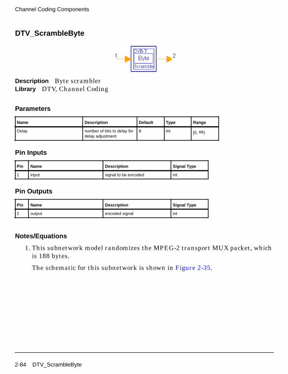
Channel Coding Components
DTV_ScrambleByte
Description Byte scramblerLibrary DTV, Channel Coding
Parameters
Pin Inputs
Pin Outputs
Notes/Equations
1. This subnetwork model randomizes the MPEG-2 transport MUX packet, whichis 188 bytes.
The schematic for this subnetwork is shown in Figure 2-35.
Name Description Default Type Range
Delay number of bits to delay fordelay adjustment
8 int [0, ∞)
Pin Name Description Signal Type
1 input signal to be encoded int
Pin Name Description Signal Type
2 output encoded signal int
2-84 DTV_ScrambleByte

Figure 2-35. DTV_ScrambleByte Schematic
2. The polynomial for the pseudo-random binary sequence generator is:
g(x) = x15 + x14 + 1
The first one-sync word byte is unrandomized. Loading of the sequence100101010000000 into the PRBS registers is initiated at the start of each of the8 transport packets.
References
[1]ETSI, Digital Video Broadcasting (DVB); Framing structure, channel codingand modulation for digital terrestrial television. EN300 744 v1.2.1, EuropeanTelecommunication Standard, July 1999.
DTV_ScrambleByte 2-85

Channel Coding Components
2-86

Chapter 3: DVB-H Components
3-1

DVB-H Components
DTV_DVBHHierReceiver
Description DVB-H baseband hierarchical receiverLibrary DTV, DVB-H
Parameters
Name Description Default Type Range
Mode Transmission mode: Mode2K, Mode 8K, Mode 4K
Mode 4K enum
OversamplingOption Oversampling ratio option:Ratio 1, Ratio 2, Ratio 4,Ratio 8, Ratio 16, Ratio 32
Ratio 1 enum
GuardInterval Guard interval (frac FFTsize)
1/32 int [0, 1]
CodeRateHP High priority stream currentconvolutional code rate:HP 1/2, HP 2/3, HP 3/4,HP 5/6, HP 7/8
HP 1/2 enum
CodeRateLP Low priority stream currentconvolutional code rate: LP1/2, LP 2/3, LP 3/4, LP 5/6,LP 7/8
LP 1/2 enum
MappingMode Signal constellations andmapping: QAM-16,QAM-64
QAM-16 enum
Alpha Non-uniform factor forDVB-H
1 int [1, ∞)
InnerInterlv Inner interleaving type:Native, In-depth
In-depth enum
SoftDecision Soft decision viterbidecoding type: Soft, Hard,Cochannel
Soft enum
TrunLen Path memory truncationlength of viterbi decodingalgorithm, in bytes
10 int [5, ∞)
3-2 DTV_DVBHHierReceiver

Pin Inputs
Pin Outputs
Notes/Equations
1. This subnetwork model implements a DVB-H baseband hierarchical receiver.
The schematic for this subnetwork is shown in Figure 3-1.
Pin Name Description Signal Type
1 Rx_Signal received OFDM signal to be demodulated complex
Pin Name Description Signal Type
2 HPBytes_Decoded decoded bytes after Reed Solomon decoder of highpriority layer
int
3 LPBytes_Decoded decoded bytes after Reed Solomon decoder of lowpriority layer
int
4 HPBytes_AftVB decoded bytes after viterbi decoder of high prioritylayer
int
5 LPBytes_AftVB decoded bytes after viterbi decoder of low prioritylayer
int
6 TPS_Bits decoded TPS information bits int
7 Constellation constellation signal after OFDM demodulation complex
DTV_DVBHHierReceiver 3-3

DVB-H Components
Figure 3-1. DTV_DVBHHierReceiver Schematic
2. Implementation
Start of OFDM symbol is detected. In the DTV_DVBTOFDMDemodsubnetwork:
• DTV_MLEstimator calculates the correlation based on guard interval;DTV_LoadFFTBuff selects the index with the maximum correlation value asthe start of FFT.
• Complex channel impulse responses are estimated on continual andscattered pilot subcarriers. Channel impulse responses of data subcarriersare interpolated based on the estimated CIR. This function is implementedby DTV_DVB2DChEstimator.
• Each subcarrier value is divided by a complex estimated channel responsecoefficient. This simple one-tap frequency domain channel responsecompensation is implemented by DTV_OFDMEqualizer.
• After equalization, DTV_DVBDemuxOFDMSym demultiplexes 1705, 3409,or 6817 subcarriers into 1512 (2K mode), 3024 (4K mode), or 6048 (8K mode)data subcarriers and 1 demodulated TPS.
The demodulated data subcarriers (16- or 64-QAM modulated) are demappedby DTV_Demapper.
3-4 DTV_DVBHHierReceiver

Demodulated soft bits are deinterleaved by DTV_DVBHInnerDeinterlv.
De-interleaved bits are inner decoded (DTV_InnerDecoder), outerde-interleaved (DTV_InterlvInt), outer decoded (DTV_RSDecoder), anddescrambled (DTV_ScrambleByte).
Fully decoded stream bytes are output as HPBytes_Decoded andLPBytes_Decoded. Partially decoded stream bytes after inner decoding areoutput as HPBytes_AftVB and LPBytes_AftVB.
The TPS signal is demodulated by DTV_DVBTPSDemod and the demodulatedbits are decoded by DTV_BCHDecoder.
Output pins of this receiver correspond to DTV_DVBHSignalSrc pins.
The number of samples of each OFDM symbol (Rx_Signal input pin) is:
• (1+GuardInterval)×2048×OversamplingOption (2K mode)
• (1+GuardInterval)×4096×OversamplingOption (4K mode)
• (1+GuardInterval)×8192×OversamplingOption (8K mode)
Output at the Constellation pin is 1705 (2K mode), 3409 (4K mode), or 6817 (8Kmode) per OFDM symbol.
3. Parameter Details
Mode specifies the 2K, 4K, or 8K transmission mode.
OversamplingOption specifies oversampling ratio 1, 2, 4, 8, 16, or 32 of thetransmission signal. If OversamplingOption=Ratio 2, the IFFT size is 4096 (2Kmode), 8192 (4K mode), or 16384 (8K mode).
GuardInterval specifies guard interval (also called cyclic extension) 1/32, 1/16,1/8, or 1/4 for DVB-H for each symbol, as a fraction of the FFT time period. Forproper demodulation, the value of the corresponding receiver must match theguard interval length actually used in the input signal.
CodeRateHP specifies the high priority stream convolutional code rate: 1/2, 2/3,3/4, 5/6, or 7/8.
CodeRateLP specifies the low priority stream convolutional code rate: 1/2, 2/3,3/4, 5/6, or 7/8.
MappingMode specifies signal constellation and mapping mode: 16- or 64-QAM.
DTV_DVBHHierReceiver 3-5

DVB-H Components
Alpha is used for signal constellation and mapping as defined in DVB-Hspecifications.
• If Alpha=1, uniform mapping of 16- or 64-QAM is used.
• If Alpha=2 or 4, non-uniform mapping of 16- or 64-QAM is used.
SoftDecision specifies the Viterbi decoding algorithm mode.
• If SoftDecision=Soft, the Viterbi decoding algorithm is a soft decision decoderand uses channel status information.
• If SoftDecision=Hard, the Viterbi decoding algorithm is a hard decisiondecoder and does not use channel status information.
• If SoftDecision=Cochannel, the Viterbi decoding algorithm is for co-channelmeasurement with PAL analog TV and digital DVB-T.
TrunLen sets truncation length (in bytes) in the Viterbi decoding algorithm.The path memory is 8×TrunLen bits in the Viterbi decoding algorithm.
4. Output Pin Delay Adjustment
There are different delays in different output pins.
The Constellation pin has 8 OFDM symbol delays. The 8 × 1705 (2K mode), 8 ×3409 (4K mode) or 8 × 6817 (8K mode) constellation output signals are not usedfor EVM calculation.
DTV_BCHDecoder uses a 68-bit block. So a Delay component with N=60 isinserted before DTV_DVBTPSDemod. Pin TPS_Bits has one DVB-H frame (68OFDM symbols) delay. The first 53 bits at TPS_Bits are not used.
Viterbi decoding introduces different delays for different path memorytruncation lengths (TrunLen parameter). For synchronization in BERmeasurements, the delay between byte-interleaver and byte de-interleavermust be adjusted to a multiple of 12 bytes and the delay between randomizerand de-randomizer must be adjusted to a multiple of 204 bytes; both delays inthe model have been adjusted to a multiple of 204 bytes.
The information bytes per one OFDM symbol in HPBytes_AftVB is calculatedas follows:
DataPerOFDMSymbol=1512 (2K mode), 3024 (4K mode), or 6048 (8K mode)
CodedBlockSize=204
CR = 1/2, 2/3, 3/4, 5/6, or 7/8
3-6 DTV_DVBHHierReceiver

DVB_DelayOFDMSymbols=8
InfoBytes_HP=2×DataPerOFDMSymbol×CR/8
The delay of HPBytes_AftVB is Delay_AftVB_HP, calculated as follows:
DelayBytes_HP=DVB_DelayOFDMSymbols ×InfoBytes_HP-(int(DVB_DelayOFDMSymbols ×InfoBytes_HP/CodedBlockSize))×CodedBlockSize
N_HP=int((TrunLen+DelayBytes_HP)/CodedBlockSize)
Delay_AftVB_HP=(1+int((DVB_DelayOFDMSymbols × InfoBytes_HP) /CodedBlockSize)+N_HP)×CodedBlockSize.
The information bytes per one OFDM symbol in LPBytes_AftVB is calculatedas follows:
DataPerOFDMSymbol=1512 (2K mode), 3024 (4K mode), or 6048 (8K mode)
CodedBlockSize=204
MapRateLP=2 for 16-QAM or 4 for 64-QAM
CR = 1/2, 2/3, 3/4, 5/6 or 7/8
InfoBytes_LP=MapRateLP×DataPerOFDMSymbol×CR/8
The delay of LPBytes_AftVB is Delay_AftVB_LP, calculated as follows:
DelayBytes_LP=DVB_DelayOFDMSymbols ×InfoBytes_LP-(int(DVB_DelayOFDMSymbols ×InfoBytes_LP/CodedBlockSize))×CodedBlockSize
N_LP=int((TrunLen+DelayBytes_LP)/CodedBlockSize)
Delay_AftVB_LP=(1+int((DVB_DelayOFDMSymbols×InfoBytes_LP) /CodedBlockSize)+N_LP)×CodedBlockSize.
HPBytes_Decoded and LPBytes_Decoded each have 8 OFDM symbol and 11transport MUX packets delays.
The delay of HPBytes_Decoded is
Delay_AftDescramble_HP=(11+1+int(DVB_DelayOFDMSymbols×InfoBytes_HP / CodedBlockSize)+N_HP)×188.
The delay of LPBytes_Decoded is
DTV_DVBHHierReceiver 3-7

DVB-H Components
Delay_AftDescramble_LP=(11+1+int(DVB_DelayOFDMSymbols×InfoBytes_LP / CodedBlockSize)+N_LP)×188.
5. When connecting the receiver to the signal source in MER and BERmeasurements, the reference signal from the signal generator should bedelayed according to the formula above.
References
[1]ETSI, Digital Video Broadcasting (DVB); Framing structure, channel codingand modulation for digital terrestrial television. EN300 744 v1.5.1, EuropeanTelecommunication Standard, November 2004.
3-8 DTV_DVBHHierReceiver

DTV_DVBHHierReceiver_RF
Description DVB-H RF hierarchical receiverLibrary DTV, DVB-H
Parameters
Name Description Default Unit Type Range
RIn Input resistance DefaultRIn Ohm real (0, ∞)
RTemp Physical temperature, indegrees C
DefaultRTemp Celsius real [-273.15, ∞)
GainImbalance Gain imbalance, Q vs I 0.0 dB real (-∞, ∞)
PhaseImbalance Phase imbalance, Q vs I 0.0 deg real (-∞, ∞)
FCarrier Carrier frequency 474.0MHz Hz real (0, ∞)
Sensitivity Voltage output sensitivity,Vout/Vin
1 real (-∞, ∞)
Phase Reference phase indegrees
0.0 deg real (-∞, ∞)
Mode Transmission mode: Mode2K, Mode 8K, Mode 4K
Mode 4K enum
OversamplingOption Oversampling ratio option:Ratio 1, Ratio 2, Ratio 4,Ratio 8, Ratio 16, Ratio 32
Ratio 1 enum
GuardInterval Guard interval (frac FFTsize)
1/32 int [0, 1]
CodeRateHP High priority stream currentconvolutional code rate:HP 1/2, HP 2/3, HP 3/4,HP 5/6, HP 7/8
HP 1/2 enum
CodeRateLP Low priority stream currentconvolutional code rate: LP1/2, LP 2/3, LP 3/4, LP 5/6,LP 7/8
LP 1/2 enum
MappingMode Signal constellations andmapping: QAM-16,QAM-64
QAM-16 enum
Alpha Non-uniform factor forDVB-H
1 int [1, ∞)
DTV_DVBHHierReceiver_RF 3-9

DVB-H Components
Pin Inputs
Pin Outputs
Notes/Equations
1. This subnetwork model implements RF hierarchical receiver functionsaccording to the DVB-H standard. The schematic for this subnetwork is shownin Figure 3-2.
The received RF signal is demodulated and the demodulated signal is fed to thebaseband receiver.
InnerInterlv Inner interleaving type:Native, In-depth
In-depth enum
SoftDecision Soft decision viterbidecoding type: Soft, Hard,Cochannel
Soft enum
TrunLen Path memory truncationlength of viterbi decodingalgorithm, in bytes
10 int [5, ∞)
Pin Name Description Signal Type
1 RF received RF signal timed
Pin Name Description Signal Type
2 HPBytes_Decoded decoded bytes after Reed Solomon decoder of highpriority layer
int
3 LPBytes_Decoded decoded bytes after Reed Solomon decoder of lowpriority layer
int
4 HPBytes_AftVB decoded bytes after Viterbi decoder of high prioritylayer
int
5 LPBytes_AftVB decoded bytes after Viterbi decoder of low prioritylayer
int
6 TPS_Bits decoded TPS information bits int
7 Constellation constellation signal after OFDM demodulation complex
Name Description Default Unit Type Range
3-10 DTV_DVBHHierReceiver_RF

Figure 3-2. DTV_DVBHHierReceiver_RF Schematic
2. The schematic for the baseband receiver is shown in Figure 3-3.
Figure 3-3. DTV_DVBHHierReceiver Schematic
3. Implementation
Start of OFDM symbol is detected. In the DTV_DVBTOFDMDemodsubnetwork:
DTV_DVBHHierReceiver_RF 3-11

DVB-H Components
• DTV_MLEstimator calculates the correlation based on guard interval;DTV_LoadFFTBuff selects the index with the maximum correlation value asthe start of FFT.
• Complex channel impulse response are estimated on continual and scatteredpilot subcarriers. Channel impulse responses of the data subcarriers areinterpolated based on the estimated CIR. DTV_DVB2DChEstimatorimplements these functions.
• Each subcarrier value is divided by a complex estimated channel responsecoefficient. This simple one-tap frequency domain channel responsecompensation is implemented by DTV_OFDMEqualizer.
• After equalization, DTV_DVBDemuxOFDMSym demultiplexes 1705, 3409,or 6817 subcarriers into 1512 (2K mode), 3024 (4K mode), or 6048 (8K mode)data subcarriers and 1 demodulated TPS.
The demodulated data subcarriers (16- or 64-QAM modulated) are demappedby DTV_Demapper.
Demodulated soft bits are deinterleaved by DTV_DVBHInnerDeinterlv.
De-interleaved bits are inner decoded (DTV_InnerDecoder), outerde-interleaved (DTV_InterlvInt), outer decoded (DTV_RSDecoder), anddescrambled (DTV_ScrambleByte).
Fully decoded stream bytes are output as HPBytes_Decoded andLPBytes_Decoded.
Partially decoded stream bytes after inner decoding are output asHPBytes_AftVB and LPBytes_AftVB.
The TPS signal is demodulated by DTV_DVBTPSDemod and the demodulatedbits are decoded by DTV_BCHDecoder.
The output pins of this receiver correspond to DTV_DVBHSignalSrc pins.
The number of samples of each OFDM symbol (Rx_Signal input pin) are:
• (1+GuardInterval)×2048×OversamplingOption (2K mode)
• (1+GuardInterval)×4096×OversamplingOption (4K mode)
• (1+GuardInterval)×8192×OversamplingOption (8K mode)
The number of Constellation output pin is 1705 (2K mode), 3409 (4K mode), or6817 (8K mode) per OFDM symbol.
3-12 DTV_DVBHHierReceiver_RF

4. Parameter Details
GainImbalance and PhaseImbalance add certain impairments to the idealoutput RF signal. Impairments are added in the order described here.
The unimpaired RF I and Q envelope voltages have gain and phase imbalanceapplied. The RF is given by:
where V1(t) is the in-phase RF envelope, V2(t) is the quadrature phase RFenvelope, g is the gain imbalance
and, φ (in degrees) is the phase imbalance.
FCarrier defines the RF frequency for the DVB signal.
Mode specifies the 2K, 4K, or 8K transmission mode.
OversamplingOption specifies oversampling ratio 1, 2, 4, 8, 16, or 32 of thetransmission signal. If OversamplingOption=Ratio 2, the IFFT size is 4096 (2Kmode), 8192 (4K mode), or 16384 (8K mode).
GuardInterval specifies guard interval (also called cyclic extension) 1/32, 1/16,1/8, or 1/4 for DVB-H for each symbol, as a fraction of the FFT time period. Forproper demodulation, the value of the corresponding receiver must match theguard interval length actually used in the input signal.
CodeRateHP specifies the high priority stream convolutional code rate: 1/2, 2/3,3/4, 5/6, or 7/8.
CodeRateLP specifies the low priority stream convolutional code rate: 1/2, 2/3,3/4, 5/6, or 7/8.
MappingMode specifies signal constellations and mapping: 16- or 64-QAM.
Alpha is used for signal constellation and mapping as defined in DVB-Hspecifications.
• If Alpha=1, uniform mapping of 16- or 64-QAM is used.
• If Alpha=2 or 4, non-uniform mapping of 16- or 64-QAM is used.
SoftDecision specifies the Viterbi decoding algorithm mode.
V3 t( ) A V1 t( ) ωct( )cos gV2 t( ) ωctφπ180---------+
sin– =
g 10
GainImbalance20
-----------------------------------------------
=
DTV_DVBHHierReceiver_RF 3-13

DVB-H Components
• If SoftDecision=Soft, the Viterbi decoding algorithm is a soft decision decoderand uses channel status information.
• If SoftDecision=Hard, the Viterbi decoding algorithm is a hard decisiondecoder and does not use channel status information.
• If SoftDecision=Cochannel, the Viterbi decoding algorithm is for co-channelmeasurement with PAL analog TV and digital DVB-T.
TrunLen sets truncation length (in bytes) in the Viterbi decoding algorithm.The path memory is 8×TrunLen bits in the Viterbi decoding algorithm.
5. Output Pin Delay Adjustment
The Constellation pin has 8 OFDM symbol delays. The 8 × 1705 (2K mode), 8 ×3409 (4K mode) or 8 × 6817 (8K mode) constellation output signals are not usedfor EVM calculation.
DTV_BCHDecoder uses a 68-bit block. So a Delay component with N=60 isinserted before DTV_DVBTPSDemod. Pin TPS_Bits has one DVB-H frame (68OFDM symbols) delay. The first 53 bits at TPS_Bits are not used.
Viterbi decoding introduces different delays for different path memorytruncation lengths (TrunLen parameter). For synchronization in BERmeasurements, the delay between byte-interleaver and byte de-interleavermust be adjusted to a multiple of 12 bytes and the delay between randomizerand de-randomizer must be adjusted to a multiple of 204 bytes; both delays inthe model have been adjusted to a multiple of 204 bytes.
The information bytes per one OFDM symbol in HPBytes_AftVB is calculatedas follows:
DataPerOFDMSymbol=1512 (2K mode), 3024 (4K mode), or 6048 (8K mode)
CodedBlockSize=204
CR = 1/2, 2/3, 3/4, 5/6, or 7/8
DVB_DelayOFDMSymbols=8
InfoBytes_HP=2×DataPerOFDMSymbol×CR/8
The delay of HPBytes_AftVB is Delay_AftVB_HP, calculated as follows:
DelayBytes_HP=DVB_DelayOFDMSymbols ×InfoBytes_HP-(int(DVB_DelayOFDMSymbols ×InfoBytes_HP/CodedBlockSize))×CodedBlockSize
3-14 DTV_DVBHHierReceiver_RF

N_HP=int((TrunLen+DelayBytes_HP)/CodedBlockSize)
Delay_AftVB_HP=(1+int((DVB_DelayOFDMSymbols × InfoBytes_HP) /CodedBlockSize)+N_HP)×CodedBlockSize.
The information bytes per one OFDM symbol in LPBytes_AftVB is calculatedas follows:
DataPerOFDMSymbol=1512 (2K mode), 3024 (4K mode), or 6048 (8K mode)
CodedBlockSize=204
MapRateLP=2 for 16-QAM or 4 for 64-QAM
CR = 1/2, 2/3, 3/4, 5/6 or 7/8
InfoBytes_LP=MapRateLP×DataPerOFDMSymbol×CR/8
The delay of LPBytes_AftVB is Delay_AftVB_LP, calculated as follows:
DelayBytes_LP=DVB_DelayOFDMSymbols ×InfoBytes_LP-(int(DVB_DelayOFDMSymbols ×InfoBytes_LP/CodedBlockSize))×CodedBlockSize
N_LP=int((TrunLen+DelayBytes_LP)/CodedBlockSize)
Delay_AftVB_LP=(1+int((DVB_DelayOFDMSymbols×InfoBytes_LP) /CodedBlockSize)+N_LP)×CodedBlockSize.
HPBytes_Decoded and LPBytes_Decoded each have 8 OFDM symbol and 11transport MUX packets delays.
The delay of HPBytes_Decoded is
Delay_AftDescramble_HP=(11+1+int(DVB_DelayOFDMSymbols×InfoBytes_HP / CodedBlockSize)+N_HP)×188.
The delay of LPBytes_Decoded is
Delay_AftDescramble_LP=(11+1+int(DVB_DelayOFDMSymbols×InfoBytes_LP / CodedBlockSize)+N_LP)×188.
6. When connecting the receiver to the signal source in MER and BERmeasurements, the reference signal from the signal generator should bedelayed according to the formula above.
References
DTV_DVBHHierReceiver_RF 3-15

DVB-H Components
[1]ETSI, Digital Video Broadcasting (DVB); Framing structure, channel codingand modulation for digital terrestrial television. EN300 744 v1.5.1, EuropeanTelecommunication Standard, November 2004.
3-16 DTV_DVBHHierReceiver_RF

DTV_DVBHHierSignalSrc
Description DVB-H base-band hierarchical signal sourceLibrary DTV, DVB-H
Parameters
Name Description Default Type Range
Mode Transmission mode: Mode2K, Mode 8K, Mode 4K
Mode 4K enum
OversamplingOption Oversampling ratio option:Ratio 1, Ratio 2, Ratio 4,Ratio 8, Ratio 16, Ratio 32
Ratio 1 enum
GuardInterval Guard interval (frac FFTsize)
1/32 real [0, 1]
CodeRateHP High priority streamconvolutional code rate:HP 1/2, HP 2/3, HP 3/4,HP 5/6, HP 7/8
HP 1/2 enum
CodeRateLP Low priority streamconvolutional code rate: LP1/2, LP 2/3, LP 3/4, LP 5/6,LP 7/8
LP 1/2 enum
MappingMode Signal constellations andmapping: QAM-16,QAM-64
QAM-16 enum
Alpha Non-uniform factor forDVB-H
1 int [1, ∞)
InnerInterlv Inner interleaving type:Native, In-depth
In-depth enum
Cell_ID Cell identifier 0 int [0, 65535]
TimeSlicing Time slicing for DVB-Hsignalling: TimeSlicingNot-used, TimeSlicingUsed
TimeSlicingNot-used
enum
MPE_FEC MPE-FEC for DVB-Hsignalling: MPE_FECNot-used, MPE_FEC used
MPE_FECNot-used
enum
TPSLength TPS length indicator (23 forversion 1.2.1, 31 forversion 1.5.1, 33 forDVB-H)
33 int [23, 37]
DTV_DVBHHierSignalSrc 3-17

DVB-H Components
Pin Inputs
Pin Outputs
Notes/Equations
1. This subnetwork model generates a DVB-H hierarchical baseband signal.
The schematic for this subnetwork, shown in Figure 3-4, includes: scrambler(DTV_ScrambleByte); outer coder (DTV_RSCoder); outer interleaver(DTV_InterlvInt); inner coder (DTV_PuncConvCoder); inner interleaver(DTV_DVBHInnerInterlv); mapper (DTV_Mapper); frame adaptation, OFDM,and guard interval insertion (DTV_DVBTOFDMMod subnetwork); and, TPSgenerator (DTV_DVBHTPS).
Pin Name Description Signal Type
1 DataHP Data input of high priority int
2 DataLP Data input of low priority int
Pin Name Description Signal Type
3 DVBH_Signal DVBH base-band hierarchical signal complex
4 HPBytes_BefCC high priority information bytes before convolutionalencoder
int
5 LPBytes_BefCC low priority information bytes before convolutionalencoder
int
6 TPS_Bits TPS information bits int
7 Constellation constellation signal before IFFT complex
3-18 DTV_DVBHHierSignalSrc

Figure 3-4. DTV_DVBHHierSignalSrc Schematic
2. The DVB-H signal source format follows the DVB specification. Figure 3-5shows the functional block diagram of the DVB-H baseband system.
Figure 3-5. DVB-H Baseband System Block Diagram
3. When native inner interleaving is selected, the signal source generates oneOFDM symbol each firing.
When InnerInterlv=In-depth inner interleaving, the signal source generates 1OFDM symbol in the 8K mode (in-depth inner interleaving does not affect the8K mode), 2 OFDM symbols in the 4K mode, and 4 OFDM symbols in the 2Kmode.
For each OFDM symbol, the Constellation pin exports 1705 (2K mode), 3409(4K mode), or 6817 (8K mode) particles.
The number of samples of each OFDM symbol (DVBH_signal pin) is:
• (1+GuardInterval)×2048×OversamplingOption (2K mode)
• (1+GuardInterval)×4096×OversamplingOption (4K mode)
• (1+GuardInterval)×8192×OversamplingOption (8K mode)
MUXAdaptation
EnergyDispersal
OuterCoder
OuterInterleaver
InnerCoder
InnerInterleaver Mapper
FrameAdaptation OFDM
GuardInterval
Insertion
MUXAdaptation
EnergyDispersal
OuterCoder
OuterInterleaver
InnerCoder
Pilot andTPS
Signals
DTV_DVBHHierSignalSrc 3-19

DVB-H Components
4. Input of the subnetwork is a transport stream (TS) defined in MPEG-2 Systems.
5. Parameter Details
Mode specifies a 2K, 4K, or 8K transmission mode as defined in DVB-Hspecification.
OversamplingOption specifies the oversampling ratio of the transmissionsignal. Oversampling ratios 1, 2, 4, 8, 16, 32 are supported in this source. IfOversamplingOption = Ratio 2, the IFFT size is 4096 (2K mode), 8192 (4Kmode), or 16384 (8K mode).
GuardInterval specifies the guard interval (also called cyclic extension) lengthfor each symbol, as a fraction of the FFT time period. Guard interval value ofthe corresponding receiver must match the guard interval length actually usedin the input signal in order for the demodulation to work properly. It takes thevalue of 1/32, 1/16, 1/8 or 1/4 for DVB-H.
CodeRateHP is defined as convolutional code rate for the high priority stream.Code rates 1/2, 2/3, 3/4, 5/6 and 7/8 are available in this source.
CodeRateLP is defined as convolutional code rate for the low priority stream.Code rates 1/2, 2/3, 3/4, 5/6 and 7/8 are available in this source.
MappingMode specifies signal constellations and mapping: 16- or 64-QAM.
Alpha is used for signal constellation and mapping (based on MappingMode).
• If Alpha=1, uniform mapping of 16- or 64-QAM is used.
• If Alpha=2 or 4, non-uniform mapping of 16- or 64-QAM is used as defined inDVB-H specification.
Cell_ID specifies the cell from which the signal comes from, it should belong to[0, 65535]. If not used, it should be set zero.
TPS_Length specifies the number of TPS information bits based on ETSI EN300744 specification:
23 (when cell identification information is not transmitted, MPE-FEC andTime Slicing information are not transmitted, DVB-T version 1.2.1).
31 (when cell identification information is transmitted, MPE-FEC and TimeSlicing information are not transmitted, DVB-T version 1.5.1).
33 (when cell identification information is transmitted, MPE-FEC and TimeSlicing information are transmitted, DVB-T version 1.5.1).
3-20 DTV_DVBHHierSignalSrc

References
[1]ETSI, Digital Video Broadcasting (DVB); Framing structure, channel codingand modulation for digital terrestrial television. EN300 744 v1.5.1, EuropeanTelecommunication Standard, November 2004.
DTV_DVBHHierSignalSrc 3-21

DVB-H Components
DTV_DVBHHierSignalSrc_RF
Description DVB-H RF hierarchical signal sourceLibrary DTV, DVB-H
Parameters
Name Description Default Unit Type Range
ROut Output resistance DefaultROut Ohm real (0, ∞)
RTemp Physical temperature, indegrees C
DefaultRTemp Celsius real [-273.15, ∞)
FCarrier Carrier frequency 474.0MHz Hz real (0, ∞)
Power Modulator output power 40mW W real (0, ∞)
BasicSamplingRate Basic sampling rate (2048/224.0)MHz Hz real (0, ∞)
MirrorSpectrum Mirror spectrum aboutcarrier? NO, YES
NO enum
GainImbalance Gain imbalance, Q vs I 0.0 dB real (-∞, ∞)
PhaseImbalance Phase imbalance, Q vs I 0.0 deg real (-∞, ∞)
I_OriginOffset I origin offset (percent) 0.0 real (-∞, ∞)
Q_OriginOffset Q origin offset (percent) 0.0 real (-∞, ∞)
IQ_Rotation IQ rotation 0.0 deg real (-∞, ∞)
Mode Transmission mode: Mode2K, Mode 8K, Mode 4K
Mode 4K enum
OversamplingOption Oversampling ratio option:Ratio 1, Ratio 2, Ratio 4,Ratio 8, Ratio 16, Ratio 32
Ratio 1 enum
GuardInterval Guard interval (frac FFTsize)
1/32 real [0, 1]
CodeRateHP High priority streamconvolutional code rate:HP 1/2, HP 2/3, HP 3/4,HP 5/6, HP 7/8
HP 1/2 enum
3-22 DTV_DVBHHierSignalSrc_RF

Pin Outputs
CodeRateLP Low priority streamconvolutional code rate: LP1/2, LP 2/3, LP 3/4, LP 5/6,LP 7/8
LP 1/2 enum
MappingMode Signal constellations andmapping: QAM-16,QAM-64
QAM-16 enum
Alpha Non-uniform factor forDVB-H
1 int [1, ∞)
InnerInterlv Inner interleaving type:Native, In-depth
In-depth enum
Cell_ID Cell identifier 0 int [0, 65535]
TimeSlicing Time slicing for DVB-Hsignalling: TimeSlicingNot-used, TimeSlicingUsed
TimeSlicingNot-used
enum
MPE_FEC MPE-FEC for DVB-Hsignalling: MPE_FECNot-used, MPE_FEC used
MPE_FECNot-used
enum
TPSLength TPS length indicator (23 forversion 1.2.1, 31 forversion 1.5.1, 33 forDVB-H)
33 int [23, 37]
DataTypeHP Payload data type with highpriority: PN9 HP, PN15 HP,FIX4 HP, _4_1_4_0 HP,_8_1_8_0 HP, _16_1_16_0HP, _32_1_32_0 HP,_64_1_64_0 HP
PN9 HP enum
DataTypeLP Payload data type with lowpriority: PN9 LP, PN15 LP,FIX4 LP, _4_1_4_0 LP,_8_1_8_0 LP, _16_1_16_0LP, _32_1_32_0 LP,_64_1_64_0 LP
PN15 LP enum
Pin Name Description Signal Type
1 RF RF hierarchical signal timed
2 DVBH_Signal DVB-H hierarchical base-band signal complex
3 HPBytes_Uncoded high priority information bytes of transport packet int
4 LPBytes_Uncoded low priority information bytes of transport packet int
5 HPBytes_BefCC high priority information bytes before convolutionalcoder
int
6 LPBytes_BefCC low priority information bytes before convolutionalcoder
int
Name Description Default Unit Type Range
DTV_DVBHHierSignalSrc_RF 3-23

DVB-H Components
Notes/Equations
1. This subnetwork model integrates an RF modulator and a DVB-H hierarchicalbaseband signal source. The baseband signal is fed to the RF modulator; afterRF modulation the timed signal is output. The schematic for this subnetwork isshown in Figure 3-6.
Figure 3-6. DTV_DVBHHierSignalSrc_RF Schematic
2. The DVB-H signal source format follows the DVB specification. Figure 3-7shows the functional block diagram of the DVB-H baseband system.
Figure 3-7. DVB-H Baseband System Block Diagram
3. The schematic for baseband signal source DTV_DVBHHierSignalSrc is shownin Figure 3-8, it includes: scrambler (DTV_ScrambleByte); outer coder
7 TPS_Bits TPS bits int
8 Constellation constellation signal before IFFT complex
Pin Name Description Signal Type
MUXAdaptation
EnergyDispersal
OuterCoder
OuterInterleaver
InnerCoder
InnerInterleaver Mapper
FrameAdaptation OFDM
GuardInterval
Insertion
MUXAdaptation
EnergyDispersal
OuterCoder
OuterInterleaver
InnerCoder
Pilot andTPS
Signals
3-24 DTV_DVBHHierSignalSrc_RF

(DTV_RSCoder); outer interleaver (DTV_InterlvInt); inner coder(DTV_PuncConvCoder); inner interleaver (DTV_DVBHInnerInterlv); mapper(DTV_Mapper); frame adaptation, OFDM, and guard interval insertion(DTV_DVBTOFDMMod subnetwork); and, TPS generator (DTV_DVBHTPS).
Figure 3-8. DTV_DVBHHierSignalSrc Schematic
When native inner interleaving is selected, the signal source generates oneOFDM symbol each firing.
When in-depth inner interleaving is selected, the signal source generates 1OFDM symbol in the 8K mode (in-depth inner interleaving does not affect 8Kmode), 2 OFDM symbols in the 4K mode, and 4 OFDM symbols in the 2K mode.
Each OFDM symbol, the Constellation pin outputs 1705 (2K mode), 3409 (4Kmode), or 6817 (8K mode) particles.
The number of samples of each OFDM symbol (DVBH_signal pin) is:
• (1+GuardInterval)×2048×OversamplingOption (2K mode)
• (1+GuardInterval)×4096×OversamplingOption (4K mode)
• (1+GuardInterval)×8192×OversamplingOption (8K mode)
4. Baseband Parameter Details
Mode is used to select a 2K, 4K, or 8K transmission mode as defined in DVB-Hspecification.
OversamplingOption specifies the oversampling ratio of the transmissionsignal. Oversampling ratios 1, 2, 4, 8, 16, 32 are supported in this source. If
DTV_DVBHHierSignalSrc_RF 3-25

DVB-H Components
OversamplingOption = Ratio 2, the IFFT size is 4096 (2K mode), 8192 (4Kmode), or 16384 (8K mode).
GuardInterval specifies the guard interval (also called cyclic extension) lengthfor each symbol, as a fraction of the FFT time period. Guard interval value ofthe corresponding receiver must match the guard interval length actually usedin the input signal in order for the demodulation to work properly. It takes thevalue of 1/32, 1/16, 1/8 or 1/4 for DVB-H.
CodeRateHP is defined as convolutional code rate for the high priority stream.Code rates 1/2, 2/3, 3/4, 5/6, and 7/8 are available in this source.
CodeRateLP is defined as convolutional code rate for the low priority stream.Code rates 1/2, 2/3, 3/4, 5/6, and 7/8 are available in this source.
MappingMode specifies signal constellations and mapping: 16- or 64-QAM.
Alpha is used for signal constellation and mapping (based on MappingMode).
• If Alpha=1, uniform mapping of 16- or 64-QAM is used.
• If Alpha=2 or 4, non-uniform mapping of 16- or 64-QAM is used as defined inDVB-H specification.
Cell_ID specifies the cell from which the signal comes from, it should belong to[0, 65535]. If not used, it should be set zero.
TPS_Length specifies the number of TPS information bits based on ETSI EN300744 specification:
23 (when cell identification information is not transmitted, MPE-FEC andTime Slicing information are not transmitted, DVB-T version 1.2.1).
31 (when cell identification information is transmitted, MPE-FEC and TimeSlicing information are not transmitted, DVB-T version 1.5.1).
33 (when cell identification information is transmitted, MPE-FEC and TimeSlicing information are transmitted, DVB-T version 1.5.1).
For DataTypeHP and DataTypeLP:
• if PN9 is selected, a 511-bit pseudo-random test pattern is generatedaccording to CCITT Recommendation O.153
• if PN15 is selected, a 32767-bit pseudo-random test pattern is generatedaccording to CCITT Recommendation O.151
• if FIX4 is selected, a zero-stream is generated
3-26 DTV_DVBHHierSignalSrc_RF

• if x_1_x_0 is selected, where x equals 4, 8, 16, 32, or 64, a periodic bit streamis generated, with the period being 2x. In one period, the first x bits are 1sand the second x bits are 0s.
5. RF Parameter Details
FCarrier defines the RF frequency for the DVB signal.
Power defines the power level for FCarrier.
BasicSamplingRate indicates the sampling rate of baseband signal, thecorresponding bandwidth of the RF signal is:
BasicSamplingRate×1705/2048 (2K mode)BasicSamplingRate×3409/4096 (4K mode)BasicSamplingRate×6817/8192 (8K mode)
The MirrorSpectrum (when set to YES) conjugates the input signal before anyother processing is done.
The GainImbalance, PhaseImbalance, I_OriginOffset, Q_OriginOffset, andIQ_Rotation parameters add certain impairments to the ideal output RF signal.Impairments are added in the order described here.
The unimpaired RF I and Q envelope voltages have gain and phase imbalanceapplied. The RF is given by:
where A is a scaling factor that depends on the Power and ROut parametersspecified by the user, V1(t) is the in-phase RF envelope, V2(t) is the quadraturephase RF envelope, g is the gain imbalance
and, φ (in degrees) is the phase imbalance.
The signal V3(t) is rotated by IQ_Rotation degrees; I_OriginOffset andQ_OriginOffset are then applied to the rotated signal. Note that the amountsspecified are percentages with respect to the output rms voltage. The outputrms voltage is given by sqrt(2×ROut×Power).
References
V3 t( ) A V1 t( ) ωct( )cos gV2 t( ) ωctφπ180---------+
sin– =
g 10
GainImbalance20
-----------------------------------------------
=
DTV_DVBHHierSignalSrc_RF 3-27

DVB-H Components
[1]ETSI, Digital Video Broadcasting (DVB); Framing structure, channel codingand modulation for digital terrestrial television. EN300 744 v1.5.1, EuropeanTelecommunication Standard, November 2004.
3-28 DTV_DVBHHierSignalSrc_RF

DTV_DVBHInnerDeinterlv
Description DVB-H inner deinterleaverLibrary DTV, DVB-HClass SDFDTV_DVBHInnerDeinterlv
Parameters
Pin Inputs
Pin Outputs
Notes/Equations
1. This model performs inner de-interleaving functions in DVB-H systems fornon-hierarchical and hierarchical transmission.
Name Description Default Type
Mode Transmission mode: DVB2k mode, DVB 8k mode,DVB 4k mode
DVB 4k mode enum
MappingMode Signal constellation andmapping: QPSK, QAM-16,QAM-64
QPSK enum
Hierarchy Hierarchical transmissionflag: Non-Hierarchical,Hierarchical
Non-Hierarchical enum
InterlvType Symbol interleaving typefor 2K and 4K mode:Native, In-depth
In-depth enum
Pin Name Description Signal Type
1 BitsIn bits to be de-interleaved real
Pin Name Description Signal Type
2 BitsHP high priority bit stream (no output in non-hierarchicaltransmission)
real
3 BitsLP low priority bit stream or non-hierarchical bit stream real
DTV_DVBHInnerDeinterlv 3-29

DVB-H Components
Inner de-interleaver functions (symbol de-interleaving, bit de-interleaving, andmultiplexing) are shown in Figure 3-9.
Figure 3-9. DTV_DVBHInnerDeinterlv Functional Block Diagram
BitDeinterleaver
I0
BitDeinterleaver
I1
BitDeinterleaver
I2
BitDeinterleaver
I3
BitDeinterleaver
I4
BitDeinterleaver
I5
SymbolDeinterleaver
SymbolDeinterleaver
a0,0, a0,1, ...
a1,0, a1,1, ...
a2,0, a2,1, ...
a3,0, a3,1, ...
a4,0, a4,1, ...
a5,0, a5,1, ...
Y0, Y1, Y2, ...
Y0, Y1, Y2, ...
a0,0, a0,1, ...
a1,0, a1,1, ...
a2,0, a2,1, ...
a3,0, a3,1, ...
a4,0, a4,1, ...
a5,0, a5,1, ...
BitDeinterleaver
I0
BitDeinterleaver
I1
BitDeinterleaver
I2
BitDeinterleaver
I3
BitDeinterleaver
I4
BitDeinterleaver
I5
MUXX0, X1, X2, ...
b0,0, b0,1, ...
b1,0, b1,1, ...
b2,0, b2,1, ...
b3,0, b3,1, ...
b4,0, b4,1, ...
b5,0, b5,1, ...
b0,0, b0,1, ...
b1,0, b1,1, ...
b2,0, b2,1, ...
b3,0, b3,1, ...
b4,0, b4,1, ...
b5,0, b5,1, ...
MUXX′0, X′1, X′2, ...
MUXX′′0, X′′1, X′′2, ...
3-30 DTV_DVBHInnerDeinterlv

2. Symbol de-interleaving
The symbol de-interleaver de-maps v bit words from the active carriers of everyone (all three modes with native inner interleaving), 2 (4K mode with in-depthinner interleaving) or 4 (2K mode with in-depth inner interleaving) consecutiveOFDM symbols. The symbol de-interleaver acts on blocks of 1512 (2K modewith native inner interleaving), 3024 (4K mode with native inner interleaving),or 6048 (8K mode, 2K mode with in-depth inner interleaving and 4K mode within-depth inner interleaving) data symbols.
The input v bit words yq is defined as:
yq = (y0,q, y1,q, ... , yv-1,q)
where v = 2 for QPSK, v = 4 for 16-QAM, and v = 6 for 64-QAM.
For native symbol de-interleaving:
In the 2K mode, vector Y=(y0, y1, y2, ... , y1511) from one OFDM symbol of vbit words is read into the symbol de-interleaver.
In the 4K mode, vector Y=(y0, y1, y2, ... , y3023) is read in.
In the 8K mode, vector Y=(y0, y1, y2, ... , y6047) is read in.
The de-interleaved vector Y' = (y'0, y'1, y'2, ... , y'Nmax-1) is defined by:
y'q = yH(q) for even symbols for q = 0, ... , Nmax-1
y'H(q) = yq for odd symbols for q = 0, ... , Nmax-1
where Nmax = 1512 (2K mode), Nmax=3024 (4K mode), and Nmax = 6048 (8Kmode). The symbol index is 0 to 67 in each frame.
For in-depth symbol de-interleaving:
When in-depth inner de-interleaver is selected, the symbol de-interleaveracts on blocks of 6048 data symbols.
In the 2K mode, vector Y=(y0, y1, y2, ... , y6047) is read in from four consecutiveOFDM symbols. For even vectors these start with symbols 0, 8, 16, 24, etc.;for odd vectors these start with symbols 4, 12, 20, 28, etc. in everysuper-frame.
DTV_DVBHInnerDeinterlv 3-31

DVB-H Components
In the 4K mode, vector Y=(y0, y1, y2, ... , y6047) is read in from two consecutiveOFDM symbols. For even vectors these start with symbols 0, 4, 8, 12, etc.; forodd vectors these start with symbols 2, 6, 10, 14, etc. in every super-frame.
The de-interleaved vector Y' = (y'0, y'1, y'2, ... , y'Nmax-1) is defined by:
y'q = yH(q) for even vectors for q = 0, ... , Nmax-1
y'H(q) = yq for odd vectors for q = 0, ... , Nmax-1
where Nmax = 6048, for 2K ,4K, or 8K modes.
In the 8K mode, the native and in-depth inner de-interleaving is the same.
The permutation function represented by H(q) is defined by:
An (Nr - 1) bit binary word R'i is defined, with Nr = log2 Mmax, where Mmax =2048 when Nmax = 1512, Mmax = 8192 when Nmax = 6048, and Mmax = 4096when Nmax = 3024, where R'i takes the following values:
A vector Ri is derived from the vector R'i by the bit permutations, that is:
i = 0,1: R'i [Nr-2, Nr-3, ... , 1, 0] = 0, 0, ... , 0, 0
i = 2: R'i [Nr-2, Nr-3, ... , 1, 0] = 0, 0, ... , 0, 1
2 < i < Mmax: R'i [Nr-3, Nr-4, ... , 1, 0] = R'i-1 [Nr-2, Nr-3, ... , 2, 1];
if M max=2048: R'i [Nr-2] = (R'i-1 [0] + R'i-1 [3]) mod 2
if M max=8192: R'i [Nr-2] = (R'i-1 [0]+R'i-1 [1] +R'i-1[4] + R'i-1 [6]) mod 2
if M max=4096: R'i [Nr-2] = (R'i-1 [0]+R'i-1 [2]) mod 2
Mmax = 2048 R'[9..0] = R'9, R'8, R'7, R'6, R'5, R'4, R'3, R'2, R'1, R'0
R[9..0] = R'2, R'5, R'8, R'3, R'7, R'0, R'1, R'4, R'6, R'9= R 9, R 8, R 7, R 6, R 5, R 4, R 3, R 2, R 1, R 0
Mmax = 8192 R'[11..0] = R'11, R'10, R'9, R'8, R'7, R'6, R'5, R'4, R'3, R'2, R'1, R'0
R[11..0] = R'10, R'7, R'4, R'6, R'0, R'5, R'11, R'2, R'9, R'3, R'1, R'8= R 11, R 10, R 9, R 8, R 7, R 6, R 5, R 4, R 3, R 2, R 1, R 0
Mmax = 4096 R'[10..0] = R'10, R'9, R'8, R'7, R'6, R'5, R'4, R'3, R'2, R'1, R'0
R[10..0] = R'9, R'3, R'7, R'10, R'0, R'8, R'4, R'1, R'5, R'6, R'2= R 10, R 9, R 8, R 7, R 6, R 5, R 4, R 3, R2 , R 1, R 0
3-32 DTV_DVBHInnerDeinterlv

Thus we get the permutation function H(q) by the following algorithm:
q = 0;
for (i = 0; i < Mmax; i = i + 1)
Similar to y, y' is made up of v bits:
y'q' = (y'0,q', y'1,q', ... , y'v-1,q')
where q' is the symbol number at the output of the symbol de-interleaver.
The vector Y' = (y'0, y'1, y'2, ... , y'Nmax-1) are divided into v sub-streams and fedinto the bit de-interleaver.
3. Bit de-interleaving
Each sub-stream from the symbol de-interleaver is processed by a separate bitde-interleaver. There are up to six de-interleavers depending on v, labelled I0 toI5: I0 and I1 are used for QPSK; I0 through I3 are used for 16-QAM; and I0through I5 are used for 64-QAM.
The block size is the same for each de-interleaver, but the de-interleavingsequence is different in each case. The bit de-interleaving block size is 126 bits.
For each bit de-interleaver, the input bit vector is defined by:
where e ranges from 0 to v-1.
The de-interleaved output vector B(e) = (be,0, be,1, be,2, ... , be,125) is defined by:
where He(w) is a permutation function that is different for each de-interleaver.
He(w) is defined as follows for each de-interleaver:
H q( ) i mod2( ) 2Nr 1–
× Ri j( ) 2j;×
j 0=
Nr 2–
∑+=
if H q( ) Nmax<( ) q q 1 ;+=
A e( ) ae 0, ae 1, ae 2, … ae 125,, , , ,( )=
be w, ae He w( ),=
DTV_DVBHInnerDeinterlv 3-33

DVB-H Components
I0: H0(w) = wI1: H1(w) = (w+63) mod 126I2: H2(w) = (w+21) mod 126I3: H3(w) = (w+84) mod 126I4: H4(w) = (w+105) mod 126I5: H5(w) = (w+42) mod 126
4. Multiplexing
The input, which consists of v sub-streams, is multiplexed into up to two bitstreams: in non-hierarchical mode, the v sub-streams are multiplexed into asingle output stream; in hierarchical mode, the first two sub-streams aremultiplexed into a high-priority stream, and the other v-2 sub-streams aremultiplexed into a low-priority stream. This applies to uniform andnon-uniform QAM modes.
QPSK:
b0,0 maps to x0b1,0 maps to x1
16-QAM non-hierarchical transmission:
b0,0 maps to x0b2,0 maps to x1b1,0 maps to x2 b3,0 maps to x3
16-QAM non-hierarchical transmission:
b0,0 maps to x'0b1,0 maps to x'1b2,0 maps to x"0b3,0 maps to x"1
64-QAM non-hierarchical transmission:
b0,0 maps to x0b2,0 maps to x1b4,0 maps to x2
3-34 DTV_DVBHInnerDeinterlv

b1,0 maps to x3b3,0 maps to x4b5,0 maps to x5
64-QAM non-hierarchical transmission:
b0,0 maps to x'0b1,0 maps to x'1b2,0 maps to x"0b4,0 maps to x"1b3,0 maps to x"2b5,0 maps to x"3
QPSK does not have hierarchical transmission.
References
[1]ETSI, Digital Video Broadcasting (DVB); Framing structure, channel codingand modulation for digital terrestrial television. EN300 744 v1.5.1, EuropeanTelecommunication Standard, November 2004.
DTV_DVBHInnerDeinterlv 3-35

DVB-H Components
DTV_DVBHInnerInterlv
Description DVB-H inner interleaverLibrary DTV, DVB-HClass SDFDTV_DVBHInnerInterlv
Parameters
Pin Inputs
Pin Outputs
Notes/Equations
1. This model performs inner-interleaving functions in DVB-H systems fornon-hierarchical and hierarchical transmission.
Name Description Default Type
Mode Transmission mode: DVB2k mode, DVB 8k mode,DVB 4k mode
DVB 4k mode enum
MappingMode Signal constellation andmapping: QPSK, QAM-16,QAM-64
QPSK enum
Hierarchy Hierarchical transmissionflag: Non-Hierarchical,Hierarchical
Non-Hierarchical enum
InterlvType Symbol interleaving typefor 2K and 4K mode:Native, In-depth
In-depth enum
Pin Name Description Signal Type
1 BitsHP high priority bit stream (connection is not needed innon-hierarchical transmission
int
2 BitsLP low priority bit stream or non-hierarchical bit stream int
Pin Name Description Signal Type
3 BitsOut inner interleaved bits int
3-36 DTV_DVBHInnerInterlv

2. Inner interleaving functions (demultiplexing, bit interleaving, and symbolinterleaving) are shown in Figure 3-10.
Figure 3-10. DTV_DVBHInnerInterlv Functional Block Diagram
a0,0, a0,1, ...
a1,0, a1,1, ...
a2,0, a2,1, ...
a3,0, a3,1, ...
a4,0, a4,1, ...
a5,0, a5,1, ...
BitInterleaver
I0
BitInterleaver
I1
BitInterleaver
I2
BitInterleaver
I3
BitInterleaver
I4
BitInterleaver
I5
SymbolInterleaver
a0,0, a0,1, ...
a1,0, a1,1, ...
a2,0, a2,1, ...
a3,0, a3,1, ...
a4,0, a4,1, ...
a5,0, a5,1, ...
Y0, Y1, Y2, ...
BitInterleaver
I0
BitInterleaver
I1
BitInterleaver
I2
BitInterleaver
I3
BitInterleaver
I4
BitInterleaver
I5
X0, X1, X2, ...
b0,0, b0,1, ...
b1,0, b1,1, ...
b2,0, b2,1, ...
b3,0, b3,1, ...
b4,0, b4,1, ...
b5,0, b5,1, ...
b0,0, b0,1, ...
b1,0, b1,1, ...
b2,0, b2,1, ...
b3,0, b3,1, ...
b4,0, b4,1, ...
b5,0, b5,1, ...
DEMUX
X′0, X′1, X′2, ...
X′′0, X′′1, X′′2, ...DEMUX
SymbolInterleaver
Y0, Y1, Y2, ...
DEMUX
DTV_DVBHInnerInterlv 3-37

DVB-H Components
3. Demultiplexing
The input, which consists of up to two bit streams, is demultiplexed into vsub-streams, where v = 2 for QPSK, v = 4 for 16-QAM, and v = 6 for 64-QAM. Innon-hierarchical mode, the single input stream is demultiplexed into vsub-streams. In hierarchical mode the high priority stream is demultiplexedinto two sub-streams and the low priority stream is demultiplexed into v-2sub-streams. This applies in both uniform and non-uniform QAM modes.
QPSK:
x0 maps to b0,0x1 maps to b1,0
16-QAM non-hierarchical transmission:
x0 maps to b0,0x1 maps to b2,0x2 maps to b1,0x3 maps to b3,0
16-QAM non-hierarchical transmission:
x'0 maps to b0,0x'1 maps to b1,0x"0 maps to b2,0x"1 maps to b3,0
64-QAM non-hierarchical transmission:
x0 maps to b0,0x1 maps to b2,0x2 maps to b4,0x3 maps to b1,0x4 maps to b3,0x5 maps to b5,0
64-QAM non-hierarchical transmission:
x'0 maps to b0,0x'1 maps to b1,0x"0 maps to b2,0
3-38 DTV_DVBHInnerInterlv

x"1 maps to b4,0x"2 maps to b3,0x"3 maps to b5,0
4. Bit Interleaving
Each sub-stream from the demultiplexer is processed by a separate bitinterleaver. There are therefore up to six interleavers depending on v, labelledI0 to I5: I0 and I1 are used for QPSK; I0 through I3 are used for 16-QAM; I0through I5 are used for 64-QAM.
Bit interleaving is performed only on the useful data. The block size is the samefor each interleaver, but the interleaving sequence is different in each case. Thebit interleaving block size is 126 bits.
for each bit interleaver, the input bit vector is defined by:
where e ranges from 0 to v-1.
The interleaved output vector A(e) = (ae,0, ae,1, ae,2, ... , ae,125) is defined by:
where He(w) is a permutation function that is different for each interleaver andis defined as:
I0: H0(w) = wI1: H1(w) = (w+63) mod 126I2: H2(w) = (w+105) mod 126I3: H3(w) = (w+42) mod 126I4: H4(w) = (w+21) mod 126I5: H5(w) = (w+84) mod 126
The outputs of the v bit interleavers are grouped to form the digital datasymbols, such that each symbol of v bits will consist of exactly one bit from eachof the v interleavers. Therefore, the output from the bit-wise interleaver is a vbit word y' that has the output of I0 as its most significant bit, i.e.:
B e( ) be 0, be 1, be 2, … be 125,, , , ,( )=
ae w, be He w( ),=
y′ a0 w, a1 w, … av 1– w,, , ,( )=
DTV_DVBHInnerInterlv 3-39

DVB-H Components
5. Symbol Interleaving
The symbol interleaver maps v bit words onto the active carriers of:
• one OFDM symbol (all modes with native inner interleaving)
• two OFDM symbols (4K mode with in-depth inner interleaving)
• four OFDM symbols (2K mode with in-depth inner interleaving)
The symbol interleaver acts on blocks of:
• 1512 data symbols (2K mode with native inner interleaving)
• 3024 data symbols (4K mode with native inner interleaving)
• 6048 data symbols (8K mode, 2K mode with in-depth inner interleaving, 4Kmode with in-depth inner interleaving)
Native symbol interleaving:
• In 2K mode, 12 groups of 126 data words from the bit interleaver are readsequentially into a vector Y' = (y'0, y'1, y'2, ... , y'1511).
• In 4K mode, a vector Y' = (y'0, y'1, y'2, ... , y'3023) is assembled from 24 groupsof 126 data words.
• In 8K mode, a vector Y' = (y'0, y'1, y'2, ... , y'6047) is assembled from 48 groupsof 126 data words.
The interleaved vector Y = (y0, y1, y2, ... , yNmax-1) is defined by:
yH(q) = y'q for even symbols for q = 0, ... , Nmax-1
yq = y'H(q) for odd symbols for q = 0, ... , Nmax-1
where Nmax = 1512 (2K mode), Nmax = 6048 (8K mode), and Nmax=3024 (4Kmode). The symbol index is from 0 to 67 in each frame.
In-depth symbol interleaving:
When in-depth inner interleaver is selected, the symbol interleaver acts onblocks of 6048 data symbols, thus 48 groups of 126 data words from the bitinterleaver are read sequentially into a vector Y' = (y'0, y'1, y'2, ... , y'6047).
The interleaved vector Y = (y0, y1, y2, ... , yNmax-1) is defined by:
yH(q) = y'q for even interleaved vectors for q = 0, ... , Nmax-1
3-40 DTV_DVBHInnerInterlv

yq = y'H(q) for odd interleaved vectors for q = 0, ... , Nmax-1
where Nmax = 6048, for mode 2K ,4K, or 8K.
In the 2K mode, interleaved vectors are mapped onto four consecutive OFDMsymbols. For even interleaved vectors these start with symbols 0, 8, 16, 24,etc.; for odd interleaved vectors these start with symbols 4, 12, 20, 28, etc. inevery super-frame.
In the 4K mode, interleaved vectors are mapped onto two consecutive OFDMsymbols. For even interleaved vectors these start with symbols 0, 4, 8, 12,etc.; for odd interleaved vectors these start with symbols 2, 6, 10, 14, etc. inevery super-frame.
For 8K mode, the native and in-depth inner de-interleaving is the same.
The permutation function represented by H(q) is defined by:
(Nr - 1) bit binary word R'i is defined with Nr = log2 Mmax,
where
Mmax = 2048 when Nmax = 1512Mmax = 8192 when Nmax = 6048Mmax = 4096 when Nmax = 3024
where R'i takes the following values:
i = 0,1: R'i [Nr-2, Nr-3, ... , 1, 0] = 0, 0, ... , 0, 0i = 2: R'i [Nr-2, Nr-3, ... , 1, 0] = 0, 0, ... , 0, 12 < i < Mmax: R'i [Nr-3, Nr-4, ... , 1, 0] = R'i-1 [Nr-2, Nr-3, ... , 2, 1]
if Mmax= 2048: R'i [Nr-2] = (R'i-1 [0] + R'i-1 [3]) mod 2if Mmax= 8192: R'i [Nr-2] = (R'i-1 [0]+R'i-1 [1] +R'i-1[4] + R'i-1 [6]) mod 2if Mmax= 4096: R'i [Nr-2] = (R'i-1 [0]+R'i-1 [2]) mod 2
A vector Ri is derived from a vector R'i by the bit permutations.
Mmax = 2048 R'[9..0] = R'9, R'8, R'7, R'6, R'5, R'4, R'3, R'2, R'1, R'0
R[9..0] = R'2, R'5, R'8, R'3, R'7, R'0, R'1, R'4, R'6, R'9= R 9, R 8, R 7, R 6, R 5, R 4, R 3, R 2, R 1, R 0
DTV_DVBHInnerInterlv 3-41

DVB-H Components
The permutation function H(q) is determined by the algorithm:
q = 0;
for (i = 0; i < Mmax; i = i + 1)
Similar to y, y' is made up of v bits:
y'q' = (y'0,q', y'1,q', ... , y'v-1,q')
where q' is the symbol number at the output of the symbol interleaver.
These y values are used to map data into the signal constellation.
6. For non-hierarchical transmission, pin 1 must not be connected.
References
[1]ETSI, Digital Video Broadcasting (DVB); Framing structure, channel codingand modulation for digital terrestrial television. EN300 744 v1.5.1, EuropeanTelecommunication Standard, November 2004.
Mmax = 8192 R'[11..0] = R'11, R'10, R'9, R'8, R'7, R'6, R'5, R'4, R'3, R'2, R'1, R'0
R[11..0] = R'10, R'7, R'4, R'6, R'0, R'5, R'11, R'2, R'9, R'3, R'1, R'8= R 11, R 10, R 9, R 8, R 7, R 6, R 5, R 4, R 3, R 2, R 1, R 0
Mmax = 4096 R'[10..0] = R'10, R'9, R'8, R'7, R'6, R'5, R'4, R'3, R'2, R'1, R'0
R[10..0] = R'9, R'3, R'7, R'10, R'0, R'8, R'4, R'1, R'5, R'6, R'2= R 10, R 9, R 8, R 7, R 6, R 5, R 4, R 3, R 2, R 1, R 0
H q( ) i mod2( ) 2Nr 1–
× Ri j( ) 2j;×
j 0=
Nr 2–
∑+=
if H q( ) Nmax<( ) q q 1 ;+=
3-42 DTV_DVBHInnerInterlv
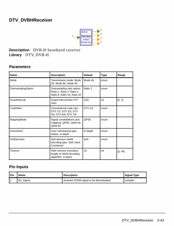
DTV_DVBHReceiver
Description DVB-H baseband receiverLibrary DTV, DVB-H
Parameters
Pin Inputs
Name Description Default Type Range
Mode Transmission mode: Mode2K, Mode 8K, Mode 4K
Mode 4K enum
OversamplingOption Oversampling ratio option:Ratio 1, Ratio 2, Ratio 4,Ratio 8, Ratio 16, Ratio 32
Ratio 1 enum
GuardInterval Guard interval (frac FFTsize)
1/32 int [0, 1]
CodeRate Convolutional code rate:DTV 1/2, DTV 2/3, DTV3/4, DTV 5/6, DTV 7/8
DTV 1/2 enum
MappingMode Signal constellations andmapping: QPSK, QAM-16,QAM-64
QPSK enum
InnerInterlv Inner interleaving type:Native, In-depth
In-depth enum
SoftDecision Soft decision viterbidecoding type: Soft, Hard,Cochannel
Soft enum
TrunLen Path memory truncationlength of viterbi decodingalgorithm, in bytes
10 int [5, ∞)
Pin Name Description Signal Type
1 Rx_Signal received OFDM signal to be demodulated complex
DTV_DVBHReceiver 3-43

DVB-H Components
Pin Outputs
Notes/Equations
1. This subnetwork model implements a DVB-H baseband receiver function basedon the DVB-H Standard. The schematic is shown in Figure 3-11.
Figure 3-11. DTV_DVBHReceiver Schematic
2. Implementation
Start of OFDM symbol is detected. In the DTV_DVBTOFDMDemodsubnetwork:
• DTV_MLEstimator calculates the correlation based on guard interval, andDTV_LoadFFTBuff selects the index with the maximum correlation value asthe start of FFT.
• Complex channel impulse response are estimated on continual and scatteredpilot subcarriers. The channel impulse responses of data subcarriers areinterpolated based on the estimated CIR. This function is implemented byDTV_DVB2DChEstimator.
• Each subcarrier value is divided by a complex estimated channel responsecoefficient. This simple one-tap frequency domain channel responsecompensation is implemented by DTV_OFDMEqualizer.
Pin Name Description Signal Type
2 Bytes_Decoded decoded bytes after Reed Solomon decoder int
3 Bytes_AftVB decoded bytes after Viterbi decoder int
4 TPS_Bits decoded TPS information bits int
5 Constellation constellation signal after OFDM demodulation complex
3-44 DTV_DVBHReceiver

• After equalization, DTV_DVBDemuxOFDMSym demultiplexes 1705, 3409,or 6817 subcarriers into 1512 (2K mode), 3024 (4K mode), or 6048 (8K mode)data subcarriers and 1 demodulated TPS.
The demodulated data subcarriers (QPSK, 16-QAM or 64-QAM modulated) aredemapped by DTV_Demapper.
Demodulated soft bits are deinterleaved by DTV_DVBHInnerDeinterlv.
De-interleaved bits are inner decoded (DTV_InnerDecoder), outerde-interleaved (DTV_InterlvInt), outer decoded (DTV_RSDecoder), anddescrambled (DTV_ScrambleByte).
Fully decoded stream bytes are output as Bytes_Decoded; partially decodedstream bytes after inner decoding are output as Bytes_AftVB.
The TPS signal is demodulated by DTV_DVBTPSDemod and the demodulatedbits are decoded by DTV_BCHDecoder.
The output pins of this receiver correspond to those of DTV_DVBHSignalSrc.
The number of samples of each OFDM symbol (Rx_Signal input pin) is:
• (1+GuardInterval)×2048×OversamplingOption for 2K mode
• (1+GuardInterval)×4096×OversamplingOption for 4K mode
• (1+GuardInterval)×8192×OversamplingOption for 8K mode
The number of Constellation output pin is 1705 (2K mode), 3409 (4K mode), or6817 (8K mode) per OFDM symbol.
3. Parameter Details
Mode is used to select transmission mode of 2K, 4K, or 8K as defined in DVB-H.
OversamplingOption specifies the oversampling ratio of the transmissionsignal. Oversampling ratios 1, 2, 4, 8, 16, 32 are supported in this source. IfOversamplingOption = Ratio 2, the IFFT size is 4096 (2K mode), 8192 (4Kmode), or 16384 (8K mode).
GuardInterval specifies the guard interval (also called cyclic extension) lengthfor each symbol, as a fraction of the FFT time period. Guard interval value ofthe corresponding receiver must match the guard interval length actually usedin the input signal in order for the demodulation to work properly. It takes thevalue of 1/32, 1/16, 1/8 or 1/4 for DVB-H.
DTV_DVBHReceiver 3-45

DVB-H Components
CodeRate is defined as convolutional code rate. Code rates 1/2, 2/3, 3/4, 5/6 and7/8 are available in this source.
MappingMode specifies signal constellations and mapping: QPSK, 16-QAM or64-QAM.
SoftDecision specifies the Viterbi decoding algorithm mode.
• If SoftDecision=Soft, the Viterbi decoding algorithm is a soft decision decoderand uses channel status information.
• If SoftDecision=Hard, the Viterbi decoding algorithm is a hard decisiondecoder and does not use channel status information.
• If SoftDecision=Cochannel, the Viterbi decoding algorithm is for co-channelmeasurement with PAL analog TV and digital DVB-T.
TrunLen sets truncation length (in bytes) in the Viterbi decoding algorithm.The path memory is 8×TrunLen bits in the Viterbi decoding algorithm.
4. Output Pin Delay Adjustment
There are different delays in different output pins.
The Constellation pin has 8 OFDM symbol delay. The 8 × 1705 (2K mode), 8 ×3409 (4K mode) or 8 × 6817 (8K mode) constellation output signals are not usedfor EVM calculation.
DTV_BCHDecoder uses a 68-bit block. So a Delay component with N=60 isinserted before DTV_DVBTPSDemod. Pin TPS_Bits has one DVB-H frame (68OFDM symbols) delay. The first 53 bits at TPS_Bits are not used.
Viterbi decoding introduces different delays for different path memorytruncation lengths (TrunLen parameter). For synchronization in BERmeasurements, the delay between byte-interleaver and byte de-interleavermust be adjusted to a multiple of 12 bytes, the delay between randomizer andde-randomizer must be adjusted to a multiple of 204 bytes; both delays in thismodel are adjusted to a multiple of 204 bytes.
The information bytes per one OFDM symbol in Bytes_AftVB is calculated asfollows:
DataPerOFDMSymbol=1512 (2K mode), 3024 (4K mode), or 6048 (8K mode)
CodedBlockSize=204
CR = 1/2, 2/3, 3/4, 5/6 or 7/8
3-46 DTV_DVBHReceiver

InfoBytes=MapRate×CR×DataPerOFDMSymbol/8
DTV_DelayOFDMSymbols=8
The delay of Bytes_AftVB is Delay_AftVB, calculated as follows:
DelayBytes=DTV_DelayOFDMSymbols×InfoBytes-(int(DelayOFDMSymbols×InfoBytes/CodedBlockSize))×CodedBlockSize,
N=int((TrunLen+DelayBytes)/CodedBlockSize)
Delay_AftVB=(1+int(DelayOFDMSymbols×InfoBytes/CodedBlockSize)+N) ×CodedBlockSize.
N is used to deal with the situation in which sum of TrunLen and DelayBytes isover one block length.
The pin Bytes_Decoded has extra 11 transport MUX packets delays.
The delay of Bytes_Decoded is
Delay_AftDescramble =(1+int(DelayOFDMSymbols×InfoBytes/CodedBlockSize)+N+11)×188.
5. When connecting the receiver to the signal source in MER and BERmeasurements, reference signal from the signal generator should be delayedaccording to the formula above.
References
[1]ETSI, Digital Video Broadcasting (DVB); Framing structure, channel codingand modulation for digital terrestrial television. EN300 744 v1.5.1, EuropeanTelecommunication Standard, November 2004.
DTV_DVBHReceiver 3-47

DVB-H Components
DTV_DVBHReceiver_RF
Description DVB-H RF receiverLibrary DTV, DVB-H
Parameters
Name Description Default Unit Type Range
RIn Input resistance DefaultRIn Ohm real (0, ∞)
RTemp Physical temperature, indegrees C
DefaultRTemp Celsius real [-273.15, ∞)
GainImbalance Gain imbalance, Q vs I 0.0 dB real (-∞, ∞)
PhaseImbalance Phase imbalance, Q vs I 0.0 deg real (-∞, ∞)
FCarrier Carrier frequency 474.0MHz Hz real (0, ∞)
Sensitivity Voltage output sensitivity,Vout/Vin
1 real (-∞, ∞)
Phase Reference phase indegrees
0.0 deg real (-∞, ∞)
Mode Transmission mode: Mode2K, Mode 8K, Mode 4K
Mode 4K enum
OversamplingOption Oversampling ratio option:Ratio 1, Ratio 2, Ratio 4,Ratio 8, Ratio 16, Ratio 32
Ratio 1 enum
GuardInterval Guard interval (frac FFTsize)
1/32 int [0, 1]
CodeRate Convolutional code rate:DTV 1/2, DTV 2/3, DTV3/4, DTV 5/6, DTV 7/8
DTV 1/2 enum
MappingMode Signal constellations andmapping: QPSK, QAM-16,QAM-64
QPSK enum
InnerInterlv Inner interleaving type:Native, In-depth
In-depth enum
SoftDecision Soft decision viterbidecoding type: Soft, Hard,Cochannel
Soft enum
TrunLen Path memory truncationlength of viterbi decodingalgorithm, in bytes
10 int [5, ∞)
3-48 DTV_DVBHReceiver_RF

Pin Inputs
Pin Outputs
Notes/Equations
1. This subnetwork model implements a DVB-H RF non-hierarchical receiverfunction. The received RF signal is demodulated and the demodulated signal isfed into baseband receiver.
The schematic for this subnetwork is shown in Figure 3-12.
Figure 3-12. DTV_DVBHReceiver_RF Schematic
Pin Name Description Signal Type
1 RF received OFDM signal to be demodulated timed
Pin Name Description Signal Type
2 Bytes_Decoded decoded bytes after Reed Solomon decoder int
3 Bytes_AftVB decoded bytes after Viterbi decoder int
4 TPS_Bits decoded TPS information bits int
5 Constellation constellation signal after OFDM demodulation complex
DTV_DVBHReceiver_RF 3-49

DVB-H Components
2. The schematic for the baseband receiver is shown in Figure 3-13.
Figure 3-13. DTV_DVBHReceiver schematic
3. Receiver functions, implemented according to the DVB-H Standard, aredescribed here.
Start of OFDM symbol is detected. In the DTV_DVBTOFDMDemodsubnetwork:
• DTV_MLEstimator calculates the correlation based on guard interval, andDTV_LoadFFTBuff selects the index with the maximum correlation value asthe start of FFT.
• Complex channel impulse response are estimated on continual and scatteredpilot subcarriers. The channel impulse responses of data subcarriers areinterpolated based on the estimated CIR. This function is implemented byDTV_DVB2DChEstimator.
• Each subcarrier value is divided by a complex estimated channel responsecoefficient. This simple one-tap frequency domain channel responsecompensation is implemented by DTV_OFDMEqualizer.
• After equalization, DTV_DVBDemuxOFDMSym demultiplexes 1705, 3409,or 6817 subcarriers into 1512 (2K mode), 3024 (4K mode), or 6048 (8K mode)data subcarriers and 1 demodulated TPS.
The demodulated data subcarriers (16- or 64-QAM modulated) are demappedby DTV_Demapper.
The demodulated soft bits are deinterleaved by DTV_DVBHInnerDeinterlv.
3-50 DTV_DVBHReceiver_RF

De-interleaved bits are inner decoded (DTV_InnerDecoder), outerde-interleaved (DTV_InterlvInt), outer decoded (DTV_RSDecoder), anddescrambled (DTV_ScrambleByte).
Fully decoded stream bytes are output as Bytes_Decoded; partially decodedstream bytes after inner decoding are output as Bytes_AftVB.
The TPS signal is demodulated by DTV_DVBTPSDemod and the demodulatedbits are decoded by DTV_BCHDecoder.
The output pins of this receiver correspond to DTV_DVBHSignalSrc.
The number of samples of each OFDM symbol (Rx_Signal input pin) is:
• (1+GuardInterval)×2048×OversamplingOption for 2K mode
• (1+GuardInterval)×4096×OversamplingOption for 4K mode
• (1+GuardInterval)×8192×OversamplingOption for 8K mode
The number of Constellation output pin is 1705 (2K mode), 3409 (4K mode), or6817 (8K mode) per OFDM symbol.
4. Parameter Details
GainImbalance and PhaseImbalance add certain impairments to the idealoutput RF signal. Impairments are added in the order described here.
The unimpaired RF I and Q envelope voltages have gain and phase imbalanceapplied. The RF is given by:
where V1(t) is the in-phase RF envelope, V2(t) is the quadrature phase RFenvelope, g is the gain imbalance
and, φ (in degrees) is the phase imbalance.
FCarrier defines the RF frequency for the DVB signal.
Mode is used to select transmission mode of 2K, 4K, or 8K as defined in DVB-H.
OversamplingOption indicates the oversampling ratio of the transmissionsignal. Oversampling ratios 1, 2, 4, 8, 16, 32 are supported in this source. If
V3 t( ) A V1 t( ) ωct( )cos gV2 t( ) ωctφπ180---------+
sin– =
g 10
GainImbalance20
-----------------------------------------------
=
DTV_DVBHReceiver_RF 3-51

DVB-H Components
OversamplingOption = Ratio 2, the IFFT size is 4096 (2K mode), 8192 (4Kmode), or 16384 (8K mode).
GuardInterval specifies the guard interval (also called cyclic extension) lengthfor each symbol, as a fraction of the FFT time period. Guard interval value ofthe corresponding receiver must match the guard interval length actually usedin the input signal in order for the demodulation to work properly. It takes thevalue of 1/32, 1/16, 1/8 or 1/4 for DVB-H.
CodeRate is defined as convolutional code rate. Code rates 1/2, 2/3, 3/4, 5/6, and7/8 are available in this source.
MappingMode specifies signal constellations and mapping: QPSK, 16-QAM or64-QAM.
SoftDecision specifies the Viterbi decoding algorithm mode.
• If SoftDecision=Soft, the Viterbi decoding algorithm is a soft decision decoderand uses channel status information.
• If SoftDecision=Hard, the Viterbi decoding algorithm is a hard decisiondecoder and does not use channel status information.
• If SoftDecision=Cochannel, the Viterbi decoding algorithm is for co-channelmeasurement with PAL analog TV and digital DVB-T.
TrunLen sets truncation length (in bytes) in the Viterbi decoding algorithm.The path memory is 8×TrunLen bits in the Viterbi decoding algorithm.
5. Output Pin Delay Adjustment
There are different delays in different output pins.
The Constellation pin has 8 OFDM symbol delay. The 8 × 1705 (2K mode), 8 ×3409 (4K mode) or 8 × 6817 (8K mode) constellation output signals are not usedfor EVM calculation.
DTV_BCHDecoder uses a 68-bit block. So a Delay component with N=60 isinserted before DTV_DVBTPSDemod. Pin TPS_Bits has one DVB-H frame (68OFDM symbols) delay. The first 53 bits at TPS_Bits are not used.
Viterbi decoding introduces different delay for different path memorytruncation length (TrunLen parameter). For synchronization in BERmeasurements, the delay between byte-interleaver and byte de-interleavermust be adjusted to a multiple of 12 bytes, the delay between randomizer and
3-52 DTV_DVBHReceiver_RF
de-randomizer must be adjusted to a multiple of 204 bytes; both delays in thismodel are adjusted to a multiple of 204 bytes.
The information bytes per one OFDM symbol in Bytes_AftVB is calculated asfollows:
DataPerOFDMSymbol=1512 (2K mode), 3024 (4K mode), or 6048 (8K mode)
CodedBlockSize=204
CR = 1/2, 2/3, 3/4, 5/6 or 7/8,
InfoBytes=MapRate×CR×DataPerOFDMSymbol/8
DTV_DelayOFDMSymbols=8
The delay of Bytes_AftVB is Delay_AftVB, calculated as follows:
DelayBytes=DTV_DelayOFDMSymbols×InfoBytes-(int(DelayOFDMSymbols×InfoBytes/CodedBlockSize))×CodedBlockSize,
N=int((TrunLen+DelayBytes)/CodedBlockSize),
Delay_AftVB=(1+int(DelayOFDMSymbols×InfoBytes/CodedBlockSize)+N) ×CodedBlockSize.
N is used to deal with the situation in which sum of TrunLen and DelayBytes isover one block length.
The pin Bytes_Decoded has extra 11 transport MUX packets delays.
The delay of Bytes_Decoded is
Delay_AftDescramble =(1+int(DelayOFDMSymbols×InfoBytes/CodedBlockSize)+N+11)×188.
6. When connecting the receiver to the signal source in MER and BERmeasurements, reference signal from the signal generator should be delayedaccording to the formula above.
References
[1]ETSI, Digital Video Broadcasting (DVB); Framing structure, channel codingand modulation for digital terrestrial television. EN300 744 v1.5.1, EuropeanTelecommunication Standard, November 2004.
DTV_DVBHReceiver_RF 3-53

DVB-H Components
DTV_DVBHSignalSrc
Description DVB-H base-band non-hierarchical signal sourceLibrary DTV, DVB-H
Parameters
Pin Inputs
Name Description Default Type Range
Mode Transmission mode: Mode2K, Mode 8K, Mode 4K
Mode 4K enum
OversamplingOption Oversampling ratio option:Ratio 1, Ratio 2, Ratio 4,Ratio 8, Ratio 16, Ratio 32
Ratio 1 enum
GuardInterval Guard interval (frac FFTsize)
1/32 real [0, 1]
CodeRate Convolutional code rate:DTV 1/2, DTV 2/3, DTV3/4, DTV 5/6, DTV 7/8
DTV 1/2 enum
MappingMode Signal constellations andmapping: QPSK, QAM-16,QAM-64
QPSK enum
InnerInterlv Inner interleaving type:Native, In-depth
In-depth enum
Cell_ID Cell identifier 0 int [0, 65535]
TimeSlicing Time slicing for DVB-Hsignalling: TimeSlicingNot-used, TimeSlicingUsed
TimeSlicingNot-used
enum
MPE_FEC MPE-FEC for DVB-Hsignalling: MPE_FECNot-used, MPE_FEC used
MPE_FECNot-used
enum
TPSLength TPS length indicator (23 forversion 1.2.1, 31 forversion 1.5.1, 33 forDVB-H)
33 int [23, 37]
Pin Name Description Signal Type
1 Data Data input in byte int
3-54 DTV_DVBHSignalSrc

Pin Outputs
Notes/Equations
1. This subnetwork model generates a DVB-H non-hierarchical baseband signal.The schematic for this subnetwork, shown in Figure 3-14, includes: scrambler(DTV_ScrambleByte); outer coder (DTV_RSCoder); outer interleaver(DTV_InterlvInt); inner coder (DTV_PuncConvCoder); inner interleaver(DTV_DVBHInnerInterlv); mapper (DTV_Mapper); frame adaptation, OFDM,and guard interval insertion (DTV_DVBTOFDMMod subnetwork); and, TPSgenerator (DTV_DVBHTPS).
Figure 3-14. DTV_DVBHSignalSrc Schematic
2. The DVB-H signal source format follows the DVB specification. Figure 3-15shows the functional block diagram of the DVB-H baseband system.
Figure 3-15. DVB-H Baseband System Block Diagram
Pin Name Description Signal Type
2 DVBH_Signal DVBH base-band hierarchical signal complex
3 Bytes_BefCC bytes before convolutional encoder int
4 TPS_Bits TPS information bits int
5 Constellation constellation signal before IFFT complex
MUXAdaptation
EnergyDispersal
OuterCoder
OuterInterleaver
InnerCoder
InnerInterleaver Mapper
FrameAdaptation OFDM
GuardInterval
Insertion
MUXAdaptation
EnergyDispersal
OuterCoder
OuterInterleaver
InnerCoder
Pilot andTPS
Signals
DTV_DVBHSignalSrc 3-55

DVB-H Components
When native inner interleaving is selected, the signal source generates oneOFDM symbol each firing.
When in-depth inner interleaving is selected, the signal source generates 1OFDM symbol in the 8K mode (that means in-depth inner interleaving does notaffect 8K mode), 2 OFDM symbols in the 4K mode, and 4 OFDM symbols in the2K mode.
Each OFDM symbol, the Constellation pin exports 1705 (2K mode), 3409 (4Kmode), or 6817 (8K mode) particles.
The number of samples of each OFDM symbol (DVBH_Signal pin) is:
• (1+GuardInterval)×2048×OversamplingOption for 2K mode
• (1+GuardInterval)×4096×OversamplingOption for 4K mode
• (1+GuardInterval)×8192×OversamplingOption for 8K mode
3. Input of the subnetwork is transport stream (TS) defined in MPEG-2 Systems.
4. Parameter Details
Mode specifies a 2K, 4K or 8K transmission mode as defined in DVB-Hspecification.
OversamplingOption specifies the oversampling ratio of the transmissionsignal. Oversampling ratios 1, 2, 4, 8, 16, 32 are supported in this source. IfOversamplingOption = Ratio 2, the IFFT size is 4096 (2K mode), 8192 (4Kmode), or 16384 (8K mode).
GuardIntervalspecifies the guard interval (also called cyclic extension) length foreach symbol, as a fraction of the FFT time period. Guard interval value of thecorresponding receiver must match the guard interval length actually used inthe input signal in order for the demodulation to work properly. It takes thevalue of 1/32, 1/16, 1/8 or 1/4 for DVB-H.
CodeRate is defined as convolutional code rate. Code rates 1/2, 2/3, 3/4, 5/6 and7/8 are available in this source.
MappingMode specifies signal constellations and mapping: QPSK, 16-QAM or64-QAM.
Cell_ID specifies the cell from which the signal comes from, it should belong to[0, 65535]. If not used, it should be set zero.
3-56 DTV_DVBHSignalSrc

TPS_Length specifies the number of TPS information bits based on ETSI EN300744 specification:
23 (when cell identification information is not transmitted, MPE-FEC andTime Slicing information are not transmitted, DVB-T version 1.2.1).
31 (when cell identification information is transmitted, MPE-FEC and TimeSlicing information are not transmitted, DVB-T version 1.5.1).
33 (when cell identification information is transmitted, MPE-FEC and TimeSlicing information are transmitted, DVB-T version 1.5.1).
References
[1]ETSI, Digital Video Broadcasting (DVB); Framing structure, channel codingand modulation for digital terrestrial television. EN300 744 v1.5.1, EuropeanTelecommunication Standard, November 2004.
DTV_DVBHSignalSrc 3-57

DVB-H Components
DTV_DVBHSignalSrc_RF
Description DVB-H RF signal sourceLibrary DTV, DVB-H
Parameters
Name Description Default Unit Type Range
ROut Output resistance DefaultROut Ohm real (0, ∞)
RTemp Physical temperature, indegrees C
DefaultRTemp Celsius real [-273.15, ∞)
FCarrier Carrier frequency 474.0MHz Hz real (0, ∞)
Power Modulator output power 40mW W real (0, ∞)
BasicSamplingRate Basic sampling rate (2048/224.0)MHz Hz real (0, ∞)
MirrorSpectrum Mirror spectrum aboutcarrier? NO, YES
NO enum
GainImbalance Gain imbalance, Q vs I 0.0 dB real (-∞, ∞)
PhaseImbalance Phase imbalance, Q vs I 0.0 deg real (-∞, ∞)
I_OriginOffset I origin offset (percent) 0.0 real (-∞, ∞)
Q_OriginOffset Q origin offset (percent) 0.0 real (-∞, ∞)
IQ_Rotation IQ rotation 0.0 deg real (-∞, ∞)
Mode Transmission mode: Mode2K, Mode 8K, Mode 4K
Mode 4K enum
OversamplingOption Oversampling ratio option:Ratio 1, Ratio 2, Ratio 4,Ratio 8, Ratio 16, Ratio 32
Ratio 1 enum
GuardInterval Guard interval (frac FFTsize)
1/32 real [0, 1]
CodeRate Convolutional code rate:DTV 1/2, DTV 2/3, DTV3/4, DTV 5/6, DTV 7/8
DTV 1/2 enum
3-58 DTV_DVBHSignalSrc_RF

Pin Outputs
Notes/Equations
1. This subnetwork model integrates an RF modulator and a DVB-Hnon-hierarchical baseband signal source. The schematic for this subnetwork isshown in Figure 3-16.
The baseband signal is fed to the RF modulator; after RF modulation the timedsignal is exported.
MappingMode Signal constellations andmapping: QPSK, QAM-16,QAM-64
QPSK enum
InnerInterlv Inner interleaving type:Native, In-depth
In-depth enum
Cell_ID Cell identifier 0 int [0, 65535]
TimeSlicing Time slicing for DVB-Hsignalling: TimeSlicingNot-used, TimeSlicingUsed
TimeSlicingNot-used
enum
MPE_FEC MPE-FEC for DVB-Hsignalling: MPE_FECNot-used, MPE_FEC used
MPE_FECNot-used
enum
TPSLength TPS length indicator (23 forversion 1.2.1, 31 forversion 1.5.1, 33 forDVB-H)
33 int [23, 37]
DataType Payload data type: PN9,PN15, FIX4, _4_1_4_0,_8_1_8_0, _16_1_16_0,_32_1_32_0, _64_1_64_0
PN9 enum
Pin Name Description Signal Type
1 RF RF signal timed
2 DVBH_Signal DVB-H base-band signal complex
3 Bytes_Uncoded information bytes of transport packet int
4 Bytes_BefCC information bytes before convolutional coder int
5 TPS_Bits TPS bits int
6 Constellation constellation signal before IFFT complex
Name Description Default Unit Type Range
DTV_DVBHSignalSrc_RF 3-59

DVB-H Components
Figure 3-16. DTV_DVBHSignalSrc_RF Schematic
2. The DVB-H signal source format follows the DVB specification. Figure 3-17shows the functional block diagram of the DVB-H baseband system.
Figure 3-17. DVB-H Baseband System Block Diagram
3. The schematic for baseband signal source DTV_DVBHSignalSrc is shown inFigure 3-18; it includes: scrambler (DTV_ScrambleByte); outer coder(DTV_RSCoder); outer interleaver (DTV_InterlvInt); inner coder(DTV_PuncConvCoder); inner interleaver (DTV_DVBHInnerInterlv); mapper(DTV_Mapper); frame adaptation, OFDM, and guard interval insertion(DTV_DVBTOFDMMod subnetwork); and, TPS generator (DTV_DVBHTPS).
MUXAdaptation
EnergyDispersal
OuterCoder
OuterInterleaver
InnerCoder
InnerInterleaver Mapper
FrameAdaptation OFDM
GuardInterval
Insertion
MUXAdaptation
EnergyDispersal
OuterCoder
OuterInterleaver
InnerCoder
Pilot andTPS
Signals
3-60 DTV_DVBHSignalSrc_RF

Figure 3-18. DTV_DVBHSignalSrc Schematic
When native inner interleaving is selected, the signal source generates oneOFDM symbol each firing.
When in-depth inner interleaving is selected, the signal source generates 1OFDM symbol in the 8K mode (that means in-depth inner interleaving does notaffect 8K mode), 2 OFDM symbols in the 4K mode, and 4 OFDM symbols in the2K mode.
Each OFDM symbol, the Constellation pin outputs 1705 (2K mode), 3409 (4Kmode), or 6817 (8K mode) particles.
The number of samples of each OFDM symbol (DVBH_signal pin) is:
• (1+GuardInterval)×2048×OversamplingOption for 2K mode
• (1+GuardInterval)×4096×OversamplingOption for 4K mode
• (1+GuardInterval)×8192×OversamplingOption for 8K mode
4. Baseband Parameter Details
Mode specifies a 2K, 4K, or 8K transmission mode as defined in DVB-Hspecification.
OversamplingOption specifies the oversampling ratio of the transmissionsignal. Oversampling ratios 1, 2, 4, 8, 16, 32 are supported in this source. IfOversamplingOption = Ratio 2, the IFFT size is 4096 (2K mode), 8192 (4Kmode), or 16384 (8K mode).
GuardInterval specifies the guard interval (also called cyclic extension) lengthfor each symbol, as a fraction of the FFT time period. Guard interval value ofthe corresponding receiver must match the guard interval length actually usedin the input signal in order for the demodulation to work properly. It takes thevalue of 1/32, 1/16, 1/8 or 1/4 for DVB-H.
DTV_DVBHSignalSrc_RF 3-61

DVB-H Components
CodeRate is defined as convolutional code rate. Code rates 1/2, 2/3, 3/4, 5/6 and7/8 are available in this source.
MappingMode specifies signal constellations and mapping: QPSK, 16-QAM or64-QAM.
Cell_ID specifies the cell from which the signal comes from, it should belong to[0, 65535]. If not used, it should be set zero.
TPS_Length specifies the number of TPS information bits based on ETSI EN300744 specification:
23 (when cell identification information is not transmitted, MPE-FEC andTime Slicing information are not transmitted, DVB-T version 1.2.1).
31 (when cell identification information is transmitted, MPE-FEC and TimeSlicing information are not transmitted, DVB-T version 1.5.1).
33 (when cell identification information is transmitted, MPE-FEC and TimeSlicing information are transmitted, DVB-T version 1.5.1).
For the DataType parameter:
• if PN9 is selected, a 511-bit pseudo-random test pattern is generatedaccording to CCITT Recommendation O.153
• if PN15 is selected, a 32767-bit pseudo-random test pattern is generatedaccording to CCITT Recommendation O.151
• if FIX4 is selected, a zero-stream is generated
• if x_1_x_0 is selected, where x equals 4, 8, 16, 32, or 64, a periodic bit streamis generated, with the period being 2x. In one period, the first x bits are 1sand the second x bits are 0s.
5. RF parameter details
FCarrier defines the RF frequency for the DVB signal.
Power defines the power level for FCarrier.
BasicSamplingRate indicates the sampling rate of baseband signal, thecorresponding bandwidth of the RF signal is: BasicSamplingRate×1705/2048(2K mode), BasicSamplingRate×3409/4096 (4K mode), orBasicSamplingRate×6817/8192 (8K mode).
The MirrorSpectrum (when set to YES) conjugates the input signal before anyother processing is done.
3-62 DTV_DVBHSignalSrc_RF

The GainImbalance, PhaseImbalance, I_OriginOffset, Q_OriginOffset, andIQ_Rotation parameters add certain impairments to the ideal output RF signal.Impairments are added in the order described here.
The unimpaired RF I and Q envelope voltages have gain and phase imbalanceapplied. The RF is given by:
where A is a scaling factor that depends on the Power and ROut parametersspecified by the user, V1(t) is the in-phase RF envelope, V2(t) is the quadraturephase RF envelope, g is the gain imbalance
and, φ (in degrees) is the phase imbalance.
The signal V3(t) is rotated by IQ_Rotation degrees; I_OriginOffset andQ_OriginOffset are then applied to the rotated signal. Note that the amountsspecified are percentages with respect to the output rms voltage. The outputrms voltage is given by sqrt(2×ROut×Power).
References
[1]ETSI, Digital Video Broadcasting (DVB); Framing structure, channel codingand modulation for digital terrestrial television. EN300 744 v1.5.1, EuropeanTelecommunication Standard, November 2004.
V3 t( ) A V1 t( ) ωct( )cos gV2 t( ) ωctφπ180---------+
sin– =
g 10
GainImbalance20
-----------------------------------------------
=
DTV_DVBHSignalSrc_RF 3-63

DVB-H Components
DTV_DVBHTPS
Description Modulated transmission parameter signal informationLibrary DTV, DVB-HClass SDFDTV_DVBHTPS
Parameters
Name Description Default Type Range
LengthIndicator TPS length indicator (23 forversion 1.2.1, 31 forversion 1.5.1, 33 forDVB-H, 6 bits)
33 int [23, 37]
Constellation Modulation scheme inDVB-H (2 bits): QPSK,QAM-16, QAM-64,Reserved Con
QPSK enum
InnerInterlv Inner interleave type (1 bit):Native, In-depth
In-depth enum
Hierarchy Signalling format for alphavalues (2 bits):Non-hierarchical, Alpha 1,Alpha 2, Alpha 4
Non-hierarchical enum
CodeRateHP High priority stream currentconvolutional code rate (3bits): HP 1/2, HP 2/3, HP3/4, HP 5/6, HP 7/8,Reserved C1 HP,Reserved C2 HP,Reserved C3 HP
HP 1/2 enum
CodeRateLP Low priority stream currentconvolutional code rate (3bits): LP 1/2, LP 2/3, LP3/4, LP 5/6, LP 7/8,Reserved C1 LP, ReservedC2 LP, Reserved C3 LP
LP 1/2 enum
GuardInterval Guard interval (frac FFTsize, 2 bits): G 1/32, G1/16, G 1/8, G 1/4
G 1/32 enum
Mode Transmission mode (2bits): DVB 2k mode, DVB8k mode, DVB 4k mode,Reserved M
DVB 4k mode enum
Cell_ID Cell identifier (between 0and 65535, 8 bits x2)
0 int [0, 65535]
3-64 DTV_DVBHTPS

Pin Outputs
Notes/Equations
1. This model generates modulated transmission parameter signaling informationused in TPS carriers in DVB-H OFDM symbols.
2. The TPS is defined over 68 consecutive OFDM symbols (referred to as oneOFDM frame). Four consecutive frames correspond to one OFDM super-frame.
The reference sequence corresponding to the TPS carriers of the first symbol ofeach OFDM frame is used to initialize the TPS modulation on each TPS carrier.
Each OFDM symbol conveys one TPS bit. Each TPS block (corresponding to oneOFDM frame) contains 68 bits, defined as:
• 1 initialization bit
• 16 synchronization bits
• 37 information bits
• 14 redundancy bits for error protection
Only 33 of the 37 information bits are used, the remaining 4 bits are reservedfor future use and are set to 0 by default.
TimeSlicing Time slicing for DVB-Hsignalling (1 bit):TimeSlicing Not-used,TimeSlicing Used
TimeSlicingNot-used
enum
MPE_FEC MPE-FEC for DVB-Hsignalling (1 bit):MPE_FEC Not-used,MPE_FEC used
MPE_FECNot-used
enum
FutureUse reserved for future use (bydefault, all 4 bits are set to0)
0 0 0 0 int array
TPS_BitsOption Select output type for pinTPS_Bits: Info 53Bits, Info54Bits, Info 53 and Parity14, Info 54 and Parity 14
Info 53Bits enum
Pin Name Description Signal Type
1 TPS TPS after BPSK modulation (68 particles per frame) complex
2 TPS_Bits TPS information bits int
Name Description Default Type Range
DTV_DVBHTPS 3-65

DVB-H Components
3. TPS data generated is described here.
The 53 original information bits (16 synchronization bits and 37 informationbits) are appended 14 parity bits by BCH (67, 53, t =2) coder; therefore, a 67-bitsequence generated.
The 67-bit sequence is then DBPSK modulated with an initialization bit 0.
Each firing, 53 (see Parameter details section) original binary data is exportedthrough the TPS_Bits pin, and the initialization bit 0 with the corresponding 67DBPSK modulated bits are exported through the TPS pin (modulated data isconverted to non-return-to-zero data before export, i.e. 0 to 1 and 1 to -1).
4. TPS bit assignments are listed in Table 3-1.
Table 3-1. TPS signalling information and format
Bit Number Format Purpose/Content
S0 0 Initialization bit for differential BPSK modulation
S1 − S160011010111101110 or1100101000010001
Synchronization word (even frame and odd frame)
S17 − S22 See Table 3-2 Length indicator (starting from and including bit s17)
S23 − S24 See Table 3-3 Frame number
S25 − S26 See Table 3-4 Constellation
S27 See Table 3-5 Inner interleaving information
S28 − S29 See Table 3-5 Hierarchy information
S30 − S32 See Table 3-6 Code rate, HP stream
S33 − S35 See Table 3-6 Code rate, LP stream
S36 − S37 See Table 3-7 Guard interval
S38 − S39 See Table 3-8 Transmission mode
S40 − S47 See Table 3-9 Cell identifier
S48 − S49 SeeTable 3-10 DVB-H service indication
S50 − S53all set to 0 by default Reserved for future use
S54 − S66BCH code Error protection
3-66 DTV_DVBHTPS

Table 3-2. TPS length indicator
Bits S17 − S22 TPS length indicator
010111 when Cell Identification information is not transmitted (23 TPSbits in use)
011111 when Cell Identification information is transmitted (31 TPS bitsin use)
100001 when Cell identification and DVB-H signalling (MPE-FEC andTime Slicing information) is transmitted (33 TPS bits in use)
Table 3-3. Signalling format for frame number
Bits S23 − S24 Frame Number
00 Frame number 1 in the super-frame
01 Frame number 2 in the super-frame
10 Frame number 3 in the super-frame
11 Frame number 4 in the super-frame
Table 3-4. Signalling format for the possible constellation patterns
Bits S25 − S26 Constellation Characteristics
00 QPSK
01 16-QAM
10 64-QAM
11 reserved
Table 3-5. Signal Format for inner interleaving and Values
Bits S27 − S29In-depth interleaverinformation Value
0xx native interleaver
1xx in-depth interleaver
x00 Non-hierarchical
x01
x10
x11
NOTE: “x” means whatever bit state.
α
α
α 1=
α 2=
α 3=
DTV_DVBHTPS 3-67

DVB-H Components
Table 3-6. Signal Format for Each Code Rate
Bits
S30 − S32 HP stream
S33 − S35 LP stream Code rate
000 1/2
001 2/3
010 3/4
011 5/6
100 7/8
101 reserved
110 reserved
111 reserved
Table 3-7. Signal Format for Each Guard Interval
Bits S36 − S37 Guard interval values
00 1/32
01 1/16
10 1/8
11 1/4
Table 3-8. Signal Format for Transmission Mode
Bits S38 − S39 Transmission mode
00 2K mode
01 8K mode
10 4K mode
11 reserved
Table 3-9. Mapping of cell_id on TPS bits
TPS bit number Frame number 1 or 3 Frame number 2 or 4
S40 cell_id b15 cell_id b7
S41 cell_id b14 cell_id b6
S42 cell_id b13 cell_id b5
3-68 DTV_DVBHTPS

5. Error Protection of TPS
The 53 bits containing TPS synchronization and information (bits s1 - s53) areextended with 14 parity bits of the BCH (67,53, t = 2) shortened code, derivedfrom the original systematic BCH (127,113, t = 2) code.
The code generator polynomial is:
The shortened BCH code is implemented by adding 60 bits (all set to 0) beforethe information bits input of a BCH (127,113, t = 2) encoder. After BCHencoding these null bits are discarded, leaving a BCH code word of 67 bits.
6. TPS Modulation
TPS cells are transmitted at the normal power level, that is, they aretransmitted with energy equal to that of the mean of all data cells, E[c × c*] = 1 .
Each TPS carrier is DBPSK modulated and conveys the same message. TheDBPSK is initialized at the beginning of each TPS block.
The following rule applies for the differential modulation of carrier k of symbol l( l > 0 ) in frame m:
S43 cell_id b12 cell_id b4
S44 cell_id b11 cell_id b3
S45 cell_id b10 cell_id b2
S46 cell_id b9 cell_id b1
S47 cell_id b8 cell_id b0
Table 3-10. DVB-H service indication
S48 S49 Transmission mode
01
xx
Time Slicing is not usedAt least one elementary stream uses Time Slicing
xx
01
MPE-FEC not usedAt least one elementary stream uses MPE-FEC
x = any bit state
Table 3-9. Mapping of cell_id on TPS bits (continued)
h x( ) x14 x9 x8 x6 x5 x4 x2 x 1+ + + + + + + +=
DTV_DVBHTPS 3-69

DVB-H Components
• if s1 = 0, then
;
• if s1 = 1, then
;
Absolute modulation of TPS carriers in the first symbol in a frame is derivedfrom the reference sequence wk as follows:
7. Parameter Details
TPS_Length indicates the number of TPS information bits based on ETSI EN300744 specification:
23 (when cell identification information is not transmitted, MPE-FEC andTime Slicing information are not transmitted, DVB-T version 1.2.1).
31 (when cell identification information is transmitted, MPE-FEC and TimeSlicing information are not transmitted, DVB-T version 1.5.1).
33 (when cell identification information is transmitted, MPE-FEC and TimeSlicing information are transmitted, DVB-T version 1.5.1).
TPS_BitsOption is used for the output type selection of pin TPS_Bits.“Info_53bits” means this pin will export s1~s53, “Info 54bits” export s0~s53, “Info53 and Parity 14” export s1~s67, and “Info 54 and Parity 14” export s0~s67.
References
[1]ETSI, Digital Video Broadcasting (DVB); Framing structure, channel codingand modulation for digital terrestrial television. EN300 744 v1.5.1, EuropeanTelecommunication Standard, November 2004.
Re cm l k, , Re cm l 1– k, , = Im cm l k, , 0=
Re cm l k, , Re cm l 1– k, , –= Im cm l k, , 0=
Re cm l k, , 2 12--- wk–
=
Im cm l k, , 0=
3-70 DTV_DVBHTPS

Chapter 4: DVB-T Components
4-1

DVB-T Components
DTV_CIRNorm
Description Soft output for soft decision decoderLibrary DTV, DVB-TClass SDFDTV_CIRNorm
Parameters
Pin Inputs
Pin Outputs
Notes/Equations
1. This model outputs soft information for a soft decision decoder. The input signalis the channel coefficient in active subcarriers (= H(i)).
• When SoftDecision=Hard, the output signal is 1.0 in all active subcarriers.
• When SoftDecision=Soft, the output signal is CSI (= |H(i)|2 / Max (|H(i)|2))which is limited to [0, 1].
Name Description Default Type
Mode transmission mode: DVB2k mode, DVB 8k mode,DVB 4k mode
DVB 2k mode enum
SoftDecision soft decision viterbidecoding type: Soft, Hard,Cochannel
Soft enum
Pin Name Description Signal Type
1 input channel coefficient in active subcarriers complex
Pin Name Description Signal Type
2 output channel status information real
4-2 DTV_CIRNorm

• When SoftDecision=Cochannel, the 1.0 output in the subcarrier signal isslightly affected by the PAL co-channel analog signal; 0.0 in other subcarriersis severely affected by the PAL co-channel analog signal.
The PAL analog signal bandwidth is 8 MHz.
Each firing, 1512 (2K mode), 3024 (4K mode), or 6048 (8K mode) tokens areproduced.
References
1. ETSI, Digital Video Broadcasting (DVB); Framing structure, channel codingand modulation for digital terrestrial television. EN300 744 v1.5.1, EuropeanTelecommunication Standard, November 2004.
DTV_CIRNorm 4-3

DVB-T Components
DTV_DVB2DChEstimator
Description Channel estimator and two-dimension channel interpolator for DVB-TLibrary DTV, DVB-TClass SDFDTV_DVB2DChEstimator
Parameters
Pin Inputs
Name Description Default Type Range
Carriers number of carriers in oneOFDM symbol
1705 int 1705 for 2kmode, 6817 for 8kmode, 3409 for 4kmode
Order FFT points=2^Order 11 int (0, ∞)†
SPperiod distance in carriersbetween nearby scatteredpilots
12 int [0, ∞)††
SPstart start position of scatteredpilots in carriers
0 int [0, ∞)††
SPoffset offset value of scatteredpilots in each symbol
3 int [0, ∞)††
SPphase initial phase of scatteredpilots
0 int [0, SPperiod/SPoffset-1]
GuardInterval guard interval (fractionalFFT size)
1/4 real [0, 1]
† Order is the order of FFT; it must satisfy 2Order ≥ Carriers †† In DVB-T systems: SPperiod=12, SPstart=0, SPoffset=3
Pin Name Description Signal Type
1 input output signals from FFT complex
4-4 DTV_DVB2DChEstimator

Pin Outputs
Notes/Equations
1. This model provides linear channel estimation and 2D channel interpolationusing collected scattered pilots; data from the active subcarriers is output.
2. The number of IntState of Length determines the number of CP (continualpilot) and TPS in each symbol; the position of CP and TPS are determinedaccording to Table 4-1 and Table 4-2, respectively.
PRBS sequences in each segment are generated according to Figure 4-1; theinitial sets of PRBS register is 11111111111. The PRBS is initialized so that thefirst output bit from the PRBS coincides with the first active carrier. A newvalue is generated by the PRBS on every used carrier in each segment (whetheror not it is a pilot).
Positions of the corresponding scattered pilots are generated as follows. For thesymbol of index l (ranging from 0 to 67), carriers for which index k belongs tosubset
are scattered pilot positions.
where p is an integer that takes all possible values ≥ 0, provided the resultingvalue for k does not exceed the valid range [Kmin, Kmax]; Kmin=0, andKmax=1704 (2K mode), Kmax=3408 (4K mode), or 6816 (8K mode). SPperiod,SPstart, SPoffset and SPphase parameters control the scattered pilotspositions.
Pin Name Description Signal Type
2 output signals in active subcarriers complex
3 Coef channel coefficient in active subcarriers complex
k Kmin 3+ l mod 4× 12p+= p integer p 0 k Kmin Kmax[ , ]∈,≥,
DTV_DVB2DChEstimator 4-5
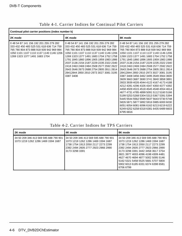
DVB-T Components
Table 4-1. Carrier Indices for Continual Pilot Carriers
Continual pilot carrier positions (index number k)
2K mode 4K mode 8K mode
0 48 54 87 141 156 192 201 255 279 282333 432 450 483 525 531 618 636 714 759765 780 804 873 888 918 939 942 969 9841050 1101 1107 1110 1137 1140 1146 12061269 1323 1377 1491 1683 1704
0 48 54 87 141 156 192 201 255 279 282333 432 450 483 525 531 618 636 714 759765 780 804 873 888 918 939 942 969 9841050 1101 1107 1110 1137 1140 1146 12061269 1323 1377 1491 1683 1704 1752 17581791 1845 1860 1896 1905 1959 1983 19862037 2136 2154 2187 2229 2235 2322 23402418 2463 2469 2484 2508 2577 2592 26222643 2646 2673 2688 2754 2805 2811 281428412844 2850 2910 2973 3027 3081 31953387 3408
0 48 54 87 141 156 192 201 255 279 282333 432 450 483 525 531 618 636 714 759765 780 804 873 888 918 939 942 969 9841050 1101 1107 1110 1137 1140 1146 12061269 1323 1377 1491 1683 1704 1752 17581791 1845 1860 1896 1905 1959 1983 19862037 2136 2154 2187 2229 2235 2322 23402418 2463 2469 2484 2508 2577 2592 26222643 2646 2673 2688 2754 2805 2811 281428412844 2850 2910 2973 3027 3081 31953387 3408 3456 3462 3495 3549 3564 36003609 3663 3687 3690 3741 3840 3858 38913933 3939 4026 4044 4122 4167 4173 41884212 4281 4296 4326 4347 4350 4377 43924458 4509 4515 4518 4545 4548 4554 46144677 4731 4785 4899 5091 5112 5160 51665199 5253 5268 5304 5313 5367 5391 53945445 5544 5562 5595 5637 5643 5730 57485826 5871 5877 5892 5916 5985 6000 60306051 6054 6081 6096 6162 6213 6219 62226249 6252 6258 6318 6381 6435 6489 66036795 6816
Table 4-2. Carrier Indices for TPS Carriers
2K mode 4K mode 8K mode
34 50 209 346 413 569 595 688 790 9011073 1219 1262 1286 1469 1594 1687
34 50 209 346 413 569 595 688 790 9011073 1219 1262 1286 1469 1594 16871738 1754 1913 2050 2117 2273 22992392 2494 2605 2777 2923 2966 29903173 3298 3391
34 50 209 346 413 569 595 688 790 9011073 1219 1262 1286 1469 1594 16871738 1754 1913 2050 2117 2273 22992392 2494 2605 2777 2923 2966 29903173 3298 3391 3442 3458 3617 37543821 3977 4003 4096 4198 4309 44814627 4670 4694 4877 5002 5095 51465162 5321 5458 5525 5681 5707 58005902 6013 6185 6331 6374 6398 65816706 6799
4-6 DTV_DVB2DChEstimator

Figure 4-1. Generation of PRBS sequence
After determining all CP, TPS, and SP positions in each symbol and the value ofthe PRBS sequence in all active carriers in symbol, this model demultiplexesinput data into TPS and TSP data. According to the TPS position and the PRBSsequence, one TPS bit in each TPS position is output.
The channel on current symbol is estimated by utilizing four symbols which arecurrent symbol and previous three symbols. So, after determining all scatteredpilots positions in four OFDM symbols, we get the pilot values from the PRBSsequence; channel estimation in scattered pilots can be determined by:
where h(i) is the channel estimation, x(i) is the received signal from channelafter FFT, and PilotValue(i) is the PRBS value corresponding to CP and SPpositions in OFDM symbol.
From the subchannel estimation in the scattered pilots positions, we can usethe linear interpolation algorithm for active subchannel estimations as follows:
where i ≤ h ≤ j, h(i), and h(j) are the subchannel estimations of scattered pilotswhich are located in different OFDM symbols and dependent on SPphaseparameter.
The active carriers and corresponding subchannel carriers are output for use inthe equalizer model. The inserted zeros in DTV_DVBLoadIFFTBuff arediscarded.
References
1
1-bitdelay
1
1-bitdelay
1
1-bitdelay
1
1-bitdelay
1
1-bitdelay
1
1-bitdelay
1
1-bitdelay
1
1-bitdelay
1
1-bitdelay
1
1-bitdelay
1
1-bitdelay
Initializationsequence
PRBS sequence starts: 1111111111100 ...
h i( ) x i( )PilotValue i( )---------------------------------------=
h k( ) αh i( ) 1 α–( )h j( )+=
α j k–j i–------------=
DTV_DVB2DChEstimator 4-7

DVB-T Components
1. ETSI, Digital Video Broadcasting (DVB); Framing structure, channel codingand modulation for digital terrestrial television. EN300 744 v1.5.1, EuropeanTelecommunication Standard, November 2004.
4-8 DTV_DVB2DChEstimator

DTV_DVBBitBlockInterlv
Description DVB bit interleaverLibrary DTV, DVB-TClass SDFDTV_DVBBitBlockInterlv
Parameters
Pin Inputs
Pin Outputs
Notes/Equations
1. This model performs bit block interleaving in DVB-T systems. The bitinterleaving block size is 126 bits in DVB-T systems. The block interleavingprocess is repeated 12 times per OFDM symbol of useful data in the 2K modeand 48 times per OFDM symbol in the 8K mode.
Name Description Default Type Range
BlockSize size of bit block to beinterleaved
126 int (0, ∞)
Offset offset of permutation ininterleaver
0 int (0, BlockSize)
Option operation option:Interleaving,De-interleaving
Interleaving enum
Pin Name Description Signal Type
1 input input data bits anytype
Pin Name Description Signal Type
2 output interleaved OFDM symbols anytype
DTV_DVBBitBlockInterlv 4-9

DVB-T Components
Each firing, this model consumes BlockSize points of input data and producesthe same amount of output data.
References
[1]ETSI, Digital Video Broadcasting (DVB); Framing structure, channel codingand modulation for digital terrestrial television. EN300 744 v1.2.1, EuropeanTelecommunication Standard, July 1999.
4-10 DTV_DVBBitBlockInterlv

DTV_DVBChannel
Description DVB channel model for transmissionLibrary DTV, DVB-TClass SDFDTV_DVBChannel
Parameters
Pin Inputs
Pin Outputs
Notes/Equations
1. This model is a multipath fading channel with 20 reflected paths to simulatethe baseband. It is described in the DVB-T specification for performanceevaluation.
2. The channel models were generated based on the following equations where x(t)and y(t) are input and output signals, respectively.
Fixed Reception F1
Name Description Default Unit Type Range
ChannelModel test path environment:Fixed Reception F1,Portable Reception P1
Fixed ReceptionF1
enum
SampleTime time interval per symbol 0.123046875e-6 sec real (0, ∞)
Pin Name Description Signal Type
1 in input signal to channel complex
Pin Name Description Signal Type
2 out output signal from channel complex
DTV_DVBChannel 4-11

DVB-T Components
The relationship of the output signal y(t) and input signal x(t) is:
where
the first term before the sum represents the line of sight ray
N is the number of echoes equal to 20
θi is the phase shift from scattering of the ith path (listed in Table 4-3)
ρi is the attenuation of the ith path (listed in Table 4-3)
τi is the relative delay of the ith path (listed in Table 4-3)
The Rician factor K (ratio of line of sight ray to reflected paths) is:
In simulations, a Rician factor K=10 dB has been used:
Portable Reception P1, Rayleigh fading
where
y t( )
ρ0x t( ) ρiej2πθi–
x t τi–( )i 1=
N
∑+
ρi2
i 0=
N
∑----------------------------------------------------------------------------=
Kρ0
2
ρi2
i 1=
N
∑---------------=
ρ0 10 ρi2
i 1=
N
∑=
y t( ) k ρiej2πθi–
x t τi–( )i 1=
N
∑=
k 1
ρi2
i 1=
N
∑---------------------=
4-12 DTV_DVBChannel

References
[1]ETSI, Digital Video Broadcasting (DVB); Framing structure, channel codingand modulation for digital terrestrial television. EN300 744 v1.2.1, EuropeanTelecommunication Standard, July 1999.
Table 4-3. Attenuation, Phase, and Delay Values for F1 and P1
i ρi τi[us] θi[rad]
1 0.057662 1.003019 4.855121
2 0.176809 5.422091 3.419109
3 0.407163 0.518650 5.864470
4 0.303585 2.751772 2.215894
5 0.258782 0.602895 3.758058
6 0.061831 1.016585 5.430202
7 0.150340 0.143556 3.952093
8 0.051534 0.153832 1.093586
9 0.185074 3.324866 5.775198
10 0.400967 1.935570 0.154459
11 0.295723 0.429948 5.928383
12 0.350825 3.228872 3.053023
13 0.262909 0.848831 0.628578
14 0.225894 0.073883 2.128544
15 0.170996 0.203952 1.099463
16 0.149723 0.194207 3.462951
17 0.240140 0.924450 3.664773
18 0.116587 1.381320 2.833799
19 0.221155 0.640512 3.334290
20 0.259730 1.368671 0.393889
DTV_DVBChannel 4-13

DVB-T Components
DTV_DVBChEstimator
Description Linear channel estimator and channel interpolator for DVB-TLibrary DTV, DVB-TClass SDFDTV_DVBChEstimator
Parameters
Pin Inputs
Name Description Default Type Range
Carriers number of carriers in oneOFDM symbol
1705 int 1705 for 2kmode, 6817 for 8kmode
Order FFT points=2^Order 11 int (0, ∞)†
SPperiod distance in carriersbetween nearby scatteredpilots
12 int [0, ∞)††
SPstart start position of scatteredpilots in carriers
0 int [0, ∞)††
SPoffset offset value of scatteredpilots in each symbol
3 int [0, ∞)††
SPphase initial phase of scatteredpilots
0 int [0, SPperiod/SPoffset-1]†††
† Order is the order of FFT; it must satisfy 2Order ≥ Carriers†† In DVB-T systems: SPperiod=12, SPstart=0, SPoffset=3††† SPphase=3 in OFDM receiver (because DTV_MLEstimator makes one OFDM symbol delay).
Pin Name Description Signal Type
1 input output signals from FFT complex
4-14 DTV_DVBChEstimator
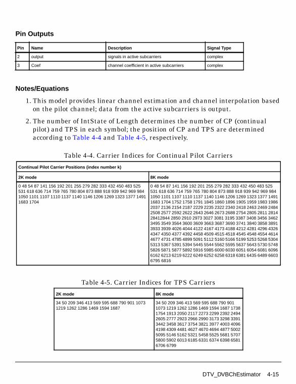
Pin Outputs
Notes/Equations
1. This model provides linear channel estimation and channel interpolation basedon the pilot channel; data from the active subcarriers is output.
2. The number of IntState of Length determines the number of CP (continualpilot) and TPS in each symbol; the position of CP and TPS are determinedaccording to Table 4-4 and Table 4-5, respectively.
Pin Name Description Signal Type
2 output signals in active subcarriers complex
3 Coef channel coefficient in active subcarriers complex
Table 4-4. Carrier Indices for Continual Pilot Carriers
Continual Pilot Carrier Positions (index number k)
2K mode 8K mode
0 48 54 87 141 156 192 201 255 279 282 333 432 450 483 525531 618 636 714 759 765 780 804 873 888 918 939 942 969 9841050 1101 1107 1110 1137 1140 1146 1206 1269 1323 1377 14911683 1704
0 48 54 87 141 156 192 201 255 279 282 333 432 450 483 525531 618 636 714 759 765 780 804 873 888 918 939 942 969 9841050 1101 1107 1110 1137 1140 1146 1206 1269 1323 1377 14911683 1704 1752 1758 1791 1845 1860 1896 1905 1959 1983 19862037 2136 2154 2187 2229 2235 2322 2340 2418 2463 2469 24842508 2577 2592 2622 2643 2646 2673 2688 2754 2805 2811 281428412844 2850 2910 2973 3027 3081 3195 3387 3408 3456 34623495 3549 3564 3600 3609 3663 3687 3690 3741 3840 3858 38913933 3939 4026 4044 4122 4167 4173 4188 4212 4281 4296 43264347 4350 4377 4392 4458 4509 4515 4518 4545 4548 4554 46144677 4731 4785 4899 5091 5112 5160 5166 5199 5253 5268 53045313 5367 5391 5394 5445 5544 5562 5595 5637 5643 5730 57485826 5871 5877 5892 5916 5985 6000 6030 6051 6054 6081 60966162 6213 6219 6222 6249 6252 6258 6318 6381 6435 6489 66036795 6816
Table 4-5. Carrier Indices for TPS Carriers
2K mode 8K mode
34 50 209 346 413 569 595 688 790 901 10731219 1262 1286 1469 1594 1687
34 50 209 346 413 569 595 688 790 9011073 1219 1262 1286 1469 1594 1687 17381754 1913 2050 2117 2273 2299 2392 24942605 2777 2923 2966 2990 3173 3298 33913442 3458 3617 3754 3821 3977 4003 40964198 4309 4481 4627 4670 4694 4877 50025095 5146 5162 5321 5458 5525 5681 57075800 5902 6013 6185 6331 6374 6398 65816706 6799
DTV_DVBChEstimator 4-15
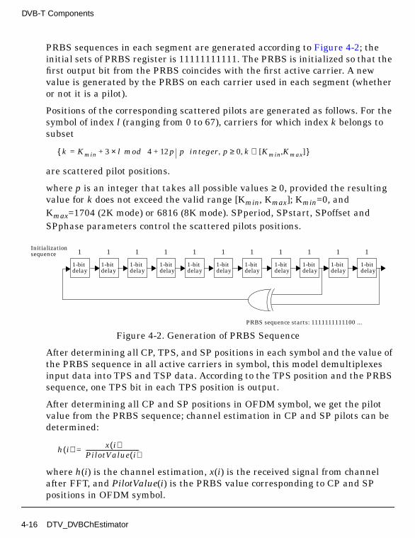
DVB-T Components
PRBS sequences in each segment are generated according to Figure 4-2; theinitial sets of PRBS register is 11111111111. The PRBS is initialized so that thefirst output bit from the PRBS coincides with the first active carrier. A newvalue is generated by the PRBS on each carrier used in each segment (whetheror not it is a pilot).
Positions of the corresponding scattered pilots are generated as follows. For thesymbol of index l (ranging from 0 to 67), carriers for which index k belongs tosubset
are scattered pilot positions.
where p is an integer that takes all possible values ≥ 0, provided the resultingvalue for k does not exceed the valid range [Kmin, Kmax]; Kmin=0, andKmax=1704 (2K mode) or 6816 (8K mode). SPperiod, SPstart, SPoffset andSPphase parameters control the scattered pilots positions.
Figure 4-2. Generation of PRBS Sequence
After determining all CP, TPS, and SP positions in each symbol and the value ofthe PRBS sequence in all active carriers in symbol, this model demultiplexesinput data into TPS and TSP data. According to the TPS position and the PRBSsequence, one TPS bit in each TPS position is output.
After determining all CP and SP positions in OFDM symbol, we get the pilotvalue from the PRBS sequence; channel estimation in CP and SP pilots can bedetermined:
where h(i) is the channel estimation, x(i) is the received signal from channelafter FFT, and PilotValue(i) is the PRBS value corresponding to CP and SPpositions in OFDM symbol.
k Kmin 3+ l mod 4× 12p+= p integer p 0 k Kmin Kmax[ , ]∈,≥,
1
1-bitdelay
1
1-bitdelay
1
1-bitdelay
1
1-bitdelay
1
1-bitdelay
1
1-bitdelay
1
1-bitdelay
1
1-bitdelay
1
1-bitdelay
1
1-bitdelay
1
1-bitdelay
Initializationsequence
PRBS sequence starts: 1111111111100 ...
h i( ) x i( )PilotValue i( )---------------------------------------=
4-16 DTV_DVBChEstimator

From the subchannel estimation in the CP and SP pilots position, we use thelinear interpolation algorithm for active subchannel estimations as follows:
where i ≤ h ≤ j, h(i), and h(j) are the subchannel estimations of CP or SP pilots.
The active carriers and corresponding subchannel carriers are output for use inthe equalizer model. The inserted zeros in DTV_DVBLoadIFFTBuff arediscarded.
References
[1]ETSI, Digital Video Broadcasting (DVB); Framing structure, channel codingand modulation for digital terrestrial television. EN300 744 v1.2.1, EuropeanTelecommunication Standard, July 1999.
h k( ) αh i( ) 1 α–( )h j( )+=
α j k–j i–------------=
DTV_DVBChEstimator 4-17

DVB-T Components
DTV_DVBDemuxOFDMSym
Description Data and TPS demux for DVB-T symbolLibrary DTV, DVB-TClass SDFDTV_DVBDemuxOFDMSym
Parameters
Pin Inputs
Name Description Default Type Range
Carriers number of carriers in oneOFDM symbol
1705 int 1705 for 2kmode; 6817 for 8kmode; 3409 for 4kmode
Data number of input data in oneOFDM symbol
1512 int 1512 for 2kmode; 6048 for 8kmode; 3024 for 4kmode
SPperiod distance in carriersbetween nearby scatteredpilots
12 int [0, ∞)†
SPstart start position of scatteredpilots in carriers
0 int [0, ∞)†
SPoffset offset value of scatteredpilots in each symbol
3 int [0, ∞)†
SPphase initial phase of scatteredpilots
0 int [0, SPperiod/SPoffset-1]††
† In DVB-T systems: SPperiod=12, SPstart=0, SPoffset=3†† SPphase=3 in the OFDM receiver (because DTV_MLEstimator makes one OFDM symbol delay).
Pin Name Description Signal Type
1 input equalized signals before de-multiplexer complex
4-18 DTV_DVBDemuxOFDMSym

Pin Outputs
Notes/Equations
1. This model demultiplexes DVB-T OFDM symbols (such as QPSK, 16- QAM, and64-QAM modulation) into TSP (transport stream packet) data, TPS(transmission parameter signal) data. Figure 4-3 shows the frame structure.
Figure 4-3. Frame Structure
2. The number of IntState of Length determines the number of CP (continualpilot) and TPS in each symbol; the position of CP and TPS are determinedaccording to Table 4-6 and Table 4-7, respectively.
PRBS sequences in each segment are generated according to Figure 4-4; theinitial sets of PRBS register is 11111111111. The PRBS in initialized so thatthe first output bit from the PRBS coincides with the first active carrier. A newvalue is generated by the PRBS on each carrier used in each segment (whetheror not it is a pilot).
Positions of the corresponding scattered pilots are generated as follows. For thesymbol of index l (ranging from 0 to 67), carriers for which index k belongs tosubset
Pin Name Description Signal Type
2 data OFDM demodulation data complex
3 TPS OFDM demodulation TPS complex
Kmin = 0
Kmax = 1704 if 2K
Kmax = 6816 if 8K
symbol 67symbol 0symbol 1symbol 2symbol 3
TPS pilots and continual pilots between Kmin and Kmax are not shown
boosted pilot
data
Kmax = 3408 if 4K
k Kmin 3+ l mod 4× 12p+= p integer p 0 k Kmin Kmax[ , ]∈,≥,
DTV_DVBDemuxOFDMSym 4-19

DVB-T Components
are scattered pilots positions.
where p is an integer that takes all possible values ≥ 0, provided the resultingvalue for k does not exceed the valid range [Kmin, Kmax]; Kmin=0, andKmax=1704 (2K mode), Kmax=3408 (4K mode), or Kmax= 6816 (8K mode).SPperiod, SPstart, SPoffset, and SPphase parameters control the scatteredpilots positions.
After determining the CP, TPS, and SP positions in each symbol and the valueof the PRBS sequence in all active carriers in the symbol, the modeldemultiplexes the input data into TPS and TSP data. According to the TPSposition and the PRBS sequence, one transmitted TPS bit is determined by themean value of the TPS positions.
where NTPS is the number of TPS in one symbol; PilotValue is the PRBSsequence in symbol; x[i] is the input data.
Except for TPS, CP, and SP positions, the remaining positions in one segmentare the TSP data positions.
Data[i] = x[i]
TPS 1NTPS------------------ x TPSposition l[ ][ ]
PilotValue TPSposition l[ ][ ]----------------------------------------------------------------------------------
l 1=
NTPS
∑=
4-20 DTV_DVBDemuxOFDMSym
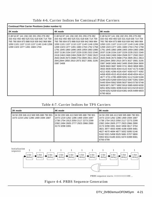
Figure 4-4. PRBS Sequence Generation
Table 4-6. Carrier Indices for Continual Pilot Carriers
Continual Pilot Carrier Positions (index number k)
2K mode 4K mode 8K mode
0 48 54 87 141 156 192 201 255 279 282333 432 450 483 525 531 618 636 714 759765 780 804 873 888 918 939 942 969 9841050 1101 1107 1110 1137 1140 1146 12061269 1323 1377 1491 1683 1704
0 48 54 87 141 156 192 201 255 279 282333 432 450 483 525 531 618 636 714 759765 780 804 873 888 918 939 942 969 9841050 1101 1107 1110 1137 1140 1146 12061269 1323 1377 1491 1683 1704 1752 17581791 1845 1860 1896 1905 1959 1983 19862037 2136 2154 2187 2229 2235 2322 23402418 2463 2469 2484 2508 2577 2592 26222643 2646 2673 2688 2754 2805 2811 281428412844 2850 2910 2973 3027 3081 31953387 3408
0 48 54 87 141 156 192 201 255 279 282333 432 450 483 525 531 618 636 714 759765 780 804 873 888 918 939 942 969 9841050 1101 1107 1110 1137 1140 1146 12061269 1323 1377 1491 1683 1704 1752 17581791 1845 1860 1896 1905 1959 1983 19862037 2136 2154 2187 2229 2235 2322 23402418 2463 2469 2484 2508 2577 2592 26222643 2646 2673 2688 2754 2805 2811 281428412844 2850 2910 2973 3027 3081 31953387 3408 3456 3462 3495 3549 3564 36003609 3663 3687 3690 3741 3840 3858 38913933 3939 4026 4044 4122 4167 4173 41884212 4281 4296 4326 4347 4350 4377 43924458 4509 4515 4518 4545 4548 4554 46144677 4731 4785 4899 5091 5112 5160 51665199 5253 5268 5304 5313 5367 5391 53945445 5544 5562 5595 5637 5643 5730 57485826 5871 5877 5892 5916 5985 6000 60306051 6054 6081 6096 6162 6213 6219 62226249 6252 6258 6318 6381 6435 6489 66036795 6816
Table 4-7. Carrier Indices for TPS Carriers
2K mode 4K mode 8K mode
34 50 209 346 413 569 595 688 790 9011073 1219 1262 1286 1469 1594 1687
34 50 209 346 413 569 595 688 790 9011073 1219 1262 1286 1469 1594 16871738 1754 1913 2050 2117 2273 22992392 2494 2605 2777 2923 2966 29903173 3298 3391
34 50 209 346 413 569 595 688 790 9011073 1219 1262 1286 1469 1594 16871738 1754 1913 2050 2117 2273 22992392 2494 2605 2777 2923 2966 29903173 3298 3391 3442 3458 3617 37543821 3977 4003 4096 4198 4309 44814627 4670 4694 4877 5002 5095 51465162 5321 5458 5525 5681 5707 58005902 6013 6185 6331 6374 6398 65816706 6799
1
1-bitdelay
1
1-bitdelay
1
1-bitdelay
1
1-bitdelay
1
1-bitdelay
1
1-bitdelay
1
1-bitdelay
1
1-bitdelay
1
1-bitdelay
1
1-bitdelay
1
1-bitdelay
Initializationsequence
PRBS sequence starts: 1111111111100 ...
DTV_DVBDemuxOFDMSym 4-21

DVB-T Components
References
1. ETSI, Digital Video Broadcasting (DVB); Framing structure, channel codingand modulation for digital terrestrial television. EN300 744 v1.5.1, EuropeanTelecommunication Standard, November 2004.
4-22 DTV_DVBDemuxOFDMSym

DTV_DVBLoadIFFTBuff
Description Data stream loader into IFFT buffer for DVB-TLibrary DTV, DVB-TClass SDFDTV_DVBLoadIFFTBuff
Parameters
Pin Inputs
Pin Outputs
Notes/Equations
1. This model loads transmission data into the IFFT buffer, which is used inDVB-T only.
2. Implementation
Name Description Default Type Range
Carriers number of carriers in oneOFDM symbol
1705 int 1705 for 2kmode; 6817 for 8kmode; 3409 for 4kmode
Order IFFT points=2^Order 13 int [1, ∞)†
† Order is the order of IFFT; it must satisfy 2Order ≥ Carriers+1
Pin Name Description Signal Type
1 input transmitted signal before IFFT complex
Pin Name Description Signal Type
2 output IFFT input signal, zero padded complex
DTV_DVBLoadIFFTBuff 4-23

DVB-T Components
Assume x(0), x(1), ... , x(N -1) are the changed signal segments,
where
N = Length × Segments + 1
M = 2Order
y(0), y(1), ... , y (M-1) are the model outputs.
Data loading is performed as follows:
References
1. ETSI, Digital Video Broadcasting (DVB); Framing structure, channel codingand modulation for digital terrestrial television. EN300 744 v1.5.1, EuropeanTelecommunication Standard, November 2004.
y i( ) x N2----- i+
= i 0 … N 1+2
-------------- 1–, ,=
y i( ) 0= i N 1+2
-------------- … M N2-----– 1–, ,=
y i( ) x i M– N2-----+
= i M N2----- … M, ,–=
4-24 DTV_DVBLoadIFFTBuff

DTV_DVBMuxOFDMSym
Description OFDM symbol multiplexer for DVB-TLibrary DTV, DVB-TClass SDFDTV_DVBMuxOFDMSym
Parameters
Pin Inputs
Name Description Default Type Range
Carriers number of carriers in oneOFDM symbol(1705,3409or 6817)
1705 int 1705 for 2kmode; 3409 for 4kmode; 6817 for 8kmode
Data number of input data in oneOFDM symbol(1512,3024or 6048)
1512 int 1512 for 2kmode; 3024 for 4kmode; 6048 for 8kmode
SPperiod distance in carriersbetween nearby scatteredpilots
12 int [0, ∞)†
SPstart start position of scatteredpilots in carriers
0 int (0, ∞)†
SPoffset offset value of SPstart ineach symbol
3 int (0, ∞)†
† In DVB-T systems: SPperiod=12, SPstart=0, SPoffset=3
Pin Name Description Signal Type
1 data data input complex
2 TPS TPS input complex
DTV_DVBMuxOFDMSym 4-25

DVB-T Components
Pin Outputs
Notes/Equations
1. This model multiplexes TSP (transport stream packet) and TPS (transmissionparameter signal) data into the DVB-T OFDM symbol. Figure 4-5 shows theframe structure.
Figure 4-5. Frame Structure
2. The number of IntState of Length determines the number of CP (continualpilot) and TPS in each symbol; the position of CP and TPS are determinedaccording to Table 4-8 and Table 4-9, respectively.
PRBS sequences in each segment are generated according to Figure 4-6; theinitial sets of PRBS register is 11111111111. The PRBS in initialized so thatthe first output bit from the PRBS coincides with the first active carrier. A newvalue is generated by the PRBS on each carrier in each segment (whether or notit is a pilot).
Positions of the corresponding scattered pilots are generated as follows. For thesymbol of index l (ranging from 0 to 67), carriers for which index k belongs tosubset
Pin Name Description Signal Type
3 output OFDM symbol data output complex
Kmin = 0
Kmax = 1704 if 2K
Kmax = 6816 if 8K
symbol 67symbol 0symbol 1symbol 2symbol 3
TPS pilots and continual pilots between Kmin and Kmax are not shown
boosted pilot
data
Kmax = 3408 if 4K
k Kmin 3+ l mod 4× 12p+= p integer p 0 k Kmin Kmax[ , ]∈,≥,
4-26 DTV_DVBMuxOFDMSym
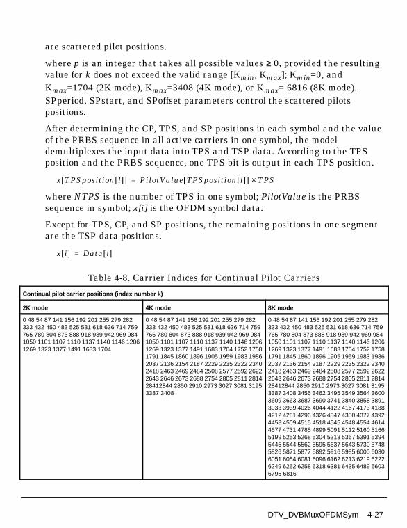
are scattered pilot positions.
where p is an integer that takes all possible values ≥ 0, provided the resultingvalue for k does not exceed the valid range [Kmin, Kmax]; Kmin=0, andKmax=1704 (2K mode), Kmax=3408 (4K mode), or Kmax= 6816 (8K mode).SPperiod, SPstart, and SPoffset parameters control the scattered pilotspositions.
After determining the CP, TPS, and SP positions in each symbol and the valueof the PRBS sequence in all active carriers in one symbol, the modeldemultiplexes the input data into TPS and TSP data. According to the TPSposition and the PRBS sequence, one TPS bit is output in each TPS position.
where NTPS is the number of TPS in one symbol; PilotValue is the PRBSsequence in symbol; x[i] is the OFDM symbol data.
Except for TPS, CP, and SP positions, the remaining positions in one segmentare the TSP data positions.
Table 4-8. Carrier Indices for Continual Pilot Carriers
Continual pilot carrier positions (index number k)
2K mode 4K mode 8K mode
0 48 54 87 141 156 192 201 255 279 282333 432 450 483 525 531 618 636 714 759765 780 804 873 888 918 939 942 969 9841050 1101 1107 1110 1137 1140 1146 12061269 1323 1377 1491 1683 1704
0 48 54 87 141 156 192 201 255 279 282333 432 450 483 525 531 618 636 714 759765 780 804 873 888 918 939 942 969 9841050 1101 1107 1110 1137 1140 1146 12061269 1323 1377 1491 1683 1704 1752 17581791 1845 1860 1896 1905 1959 1983 19862037 2136 2154 2187 2229 2235 2322 23402418 2463 2469 2484 2508 2577 2592 26222643 2646 2673 2688 2754 2805 2811 281428412844 2850 2910 2973 3027 3081 31953387 3408
0 48 54 87 141 156 192 201 255 279 282333 432 450 483 525 531 618 636 714 759765 780 804 873 888 918 939 942 969 9841050 1101 1107 1110 1137 1140 1146 12061269 1323 1377 1491 1683 1704 1752 17581791 1845 1860 1896 1905 1959 1983 19862037 2136 2154 2187 2229 2235 2322 23402418 2463 2469 2484 2508 2577 2592 26222643 2646 2673 2688 2754 2805 2811 281428412844 2850 2910 2973 3027 3081 31953387 3408 3456 3462 3495 3549 3564 36003609 3663 3687 3690 3741 3840 3858 38913933 3939 4026 4044 4122 4167 4173 41884212 4281 4296 4326 4347 4350 4377 43924458 4509 4515 4518 4545 4548 4554 46144677 4731 4785 4899 5091 5112 5160 51665199 5253 5268 5304 5313 5367 5391 53945445 5544 5562 5595 5637 5643 5730 57485826 5871 5877 5892 5916 5985 6000 60306051 6054 6081 6096 6162 6213 6219 62226249 6252 6258 6318 6381 6435 6489 66036795 6816
x TPSposition l[ ][ ] PilotValue TPSposition l[ ][ ] TPS×=
x i[ ] Data i[ ]=
DTV_DVBMuxOFDMSym 4-27

DVB-T Components
Figure 4-6. PRBS Sequence Generation
References
1. ETSI, Digital Video Broadcasting (DVB); Framing structure, channel codingand modulation for digital terrestrial television. EN300 744 v1.5.1, EuropeanTelecommunication Standard, November 2004.DT
Table 4-9. Carrier Indices for TPS Carriers
2K mode 4K mode 8K mode
34 50 209 346 413 569 595 688 790 9011073 1219 1262 1286 1469 1594 1687
34 50 209 346 413 569 595 688 790 9011073 1219 1262 1286 1469 1594 16871738 1754 1913 2050 2117 2273 22992392 2494 2605 2777 2923 2966 29903173 3298 3391
34 50 209 346 413 569 595 688 790 9011073 1219 1262 1286 1469 1594 16871738 1754 1913 2050 2117 2273 22992392 2494 2605 2777 2923 2966 29903173 3298 3391 3442 3458 3617 37543821 3977 4003 4096 4198 4309 44814627 4670 4694 4877 5002 5095 51465162 5321 5458 5525 5681 5707 58005902 6013 6185 6331 6374 6398 65816706 6799
1
1-bitdelay
1
1-bitdelay
1
1-bitdelay
1
1-bitdelay
1
1-bitdelay
1
1-bitdelay
1
1-bitdelay
1
1-bitdelay
1
1-bitdelay
1
1-bitdelay
1
1-bitdelay
Initializationsequence
PRBS sequence starts: 1111111111100 ...
4-28 DTV_DVBMuxOFDMSym

DTV_DVBSymDeinterlv2b
Description Symbol de-interleaver with 2 branchesLibrary DTV, DVB-TClass SDFDTV_DVBSymDeinterlv2bDerived From DTV_DVBSymInterlv
Parameters
Pin Inputs
Pin Outputs
Notes/Equations
1. This model performs symbol de-interleaving in DVB-T systems. Each firing, itconsumes 1512 (2K mode) or 6048 (8K mode) data symbols at the input andoutputs them to each output pin after de-interleaving.
2. This model is the reverse of the process used for DTV_DVBSymInterlv2b. Theinterleaving algorithm is described in DTV_DVBSymInterlv2b.
3. This model is one of three symbol de-interleavers with data symbol bit output.2-, 4-, and 6-bit data symbol de-interleavers are used for QPSK, 16-QAM, and
Name Description Default Type
Mode DVB OFDM mode: DVB 2kmode, DVB 8k mode
DVB 2k mode enum
Pin Name Description Signal Type
1 input interleaved OFDM symbol bits anytype
Pin Name Description Signal Type
2 outb0 data symbol bit 0 anytype
3 outb1 data symbol bit 1 anytype
DTV_DVBSymDeinterlv2b 4-29

DVB-T Components
64-QAM, respectively; after constellation mapping de-mapping, a complexsymbol interleaver is used before constellation de-mapping. These models usethe same permutation sequence.
References
[1]ETSI, Digital Video Broadcasting (DVB); Framing structure, channel codingand modulation for digital terrestrial television. EN300 744 v1.2.1, EuropeanTelecommunication Standard, July 1999.
4-30 DTV_DVBSymDeinterlv2b

DTV_DVBSymDeinterlv4b
Description Symbol de-interleaver with 4 branchesLibrary DTV, DVB-TClass SDFDTV_DVBSymDeinterlv4bDerived From DTV_DVBSymInterlv
Parameters
Pin Inputs
Pin Outputs
Notes/Equations
1. This model performs symbol de-interleaving in DVB-T systems. Each firing, itconsumes 1512 (2K mode) or 6048 (8K mode) data symbols at the input andoutputs them to each output pin after de-interleaving.
2. This model is the reverse of the process used for DTV_DVBSymInterlv4b. Theinterleaving algorithm is described in DTV_DVBSymInterlv4b.
Name Description Default Type
Mode DVB OFDM mode: DVB 2kmode, DVB 8k mode
DVB 2k mode enum
Pin Name Description Signal Type
1 input interleaved OFDM symbol bits anytype
Pin Name Description Signal Type
2 outb0 data symbol bit 0 anytype
3 outb1 data symbol bit 1 anytype
4 outb2 data symbol bit 2 anytype
5 outb3 data symbol bit 3 anytype
DTV_DVBSymDeinterlv4b 4-31

DVB-T Components
3. This model is one of three symbol de-interleavers with data symbol bit output.2-, 4-, and 6- data symbol de-interleavers are used for QPSK, 16-QAM, and64-QAM, respectively; after constellation mapping de-mapping, a complexsymbol interleaver is used before constellation de-mapping. These models usethe same permutation sequence.
References
[1]ETSI, Digital Video Broadcasting (DVB); Framing structure, channel codingand modulation for digital terrestrial television. EN300 744 v1.2.1, EuropeanTelecommunication Standard, July 1999.
4-32 DTV_DVBSymDeinterlv4b

DTV_DVBSymDeinterlv6b
Description Symbol de-interleaver with 6 branchesLibrary DTV, DVB-TClass SDFDTV_DVBSymDeinterlv6bDerived From DTV_DVBSymInterlv
Parameters
Pin Inputs
Pin Outputs
Notes/Equations
1. This model performs symbol de-interleaving in DVB-T systems. Each firing, itconsumes 1512 (2K mode) or 6048 (8K mode) data symbols at the input andoutputs them to each output pin after de-interleaving.
Name Description Default Type
Mode DVB OFDM mode: DVB 2kmode, DVB 8k mode
DVB 2k mode enum
Pin Name Description Signal Type
1 input interleaved OFDM symbol bits anytype
Pin Name Description Signal Type
2 outb0 data symbol bit 0 anytype
3 outb1 data symbol bit 1 anytype
4 outb2 data symbol bit 2 anytype
5 outb3 data symbol bit 3 anytype
6 outb4 data symbol bit 4 anytype
7 outb5 data symbol bit 5 anytype
DTV_DVBSymDeinterlv6b 4-33

DVB-T Components
2. This model is the reverse of the process used for DTV_DVBSymInterlv6b. Theinterleaving algorithm is described in DTV_DVBSymInterlv6b.
3. This model is one of three symbol de-interleavers with data symbol bit output.2-, 4-, and 6-bit data symbol de-interleavers are used for QPSK, 16-QAM, and64-QAM, respectively; after constellation mapping de-mapping, a complexsymbol interleaver is used before constellation de-mapping. These models usethe same permutation sequence.
References
[1]ETSI, Digital Video Broadcasting (DVB); Framing structure, channel codingand modulation for digital terrestrial television. EN300 744 v1.2.1, EuropeanTelecommunication Standard, July 1999.
4-34 DTV_DVBSymDeinterlv6b

DTV_DVBSymInterlv2b
Description Symbol interleaver with 2 branchesLibrary DTV, DVB-TClass SDFDTV_DVBSymInterlv2bDerived From DTV_DVBSymInterlv
Parameters
Pin Inputs
Pin Outputs
Notes/Equations
1. This model performs symbol interleaving in DVB-T systems. Each firing, itconsumes 1512 (2K mode) or 6048 (8K mode) bits data in each input pin, andoutputs them after interleaving. The interleaving algorithm is described in note2.
2. This model is one of the three symbol interleavers with data symbol bit inputs.2-, 4-, and 6-bit data symbol interleavers are used for QPSK, 16-QAM, and64-QAM, respectively, before constellation mapping; a complex symbol
Name Description Default Type
Mode DVB OFDM mode: DVB 2kmode, DVB 8k mode
DVB 2k mode enum
Pin Name Description Signal Type
1 inb0 data symbol bit 0 anytype
2 inb1 data symbol bit 1 anytype
Pin Name Description Signal Type
3 output interleaved OFDM symbol bits anytype
DTV_DVBSymInterlv2b 4-35

DVB-T Components
interleaver is used after constellation mapping. These models use the samepermutation sequence.
Interleaving Algorithm
Define input vector Y′ and interleaved vector Y as:
for even symbols for
for odd symbols for
where in 2K mode and in 8K mode.
H(q) is a permutation function defined by the following:
An bit binary word is defined, with ,
where in 2K mode and in the 8K mode,
where takes the following values:
i = 0,1:
i = 2:
2 < i < :
;
in the 2K mode:
in the 8K mode:
A vector is derived from vector by bit permutations given in Table 4-10and Table 4-11.
Y ' y'0 y'1 y'2 … , y'Nmax 1–, , ,( )=
Y y0 y1 y2 … , yNmax 1–, , ,( )=
Y H q( ) Y 'q= q 0 … Nmax 1–,=
Yq Y 'H q( )= q 0 … Nmax 1–,=
Nmax 1512= Nmax 6048=
Nr 1–( ) R'i Nr 2 Mmax( )log=
Mmax 1512= Mmax 2048=
R'i
R'i Nr 2– Nr 3– … 1 0, , , ,[ ] 0 0 … 0 0, , , ,( )=
R'i Nr 2– Nr 3– … 1 0, , , ,[ ] 0 0 … 0 1, , , ,( )=
Mmax
R'i Nr 3– Nr 4– … 1 0, , , ,[ ] R'i 1– Nr 2– Nr 3– … 1 0, , , ,[=
R'i 9[ ] R'i 1– 0[ ] R'i 1– 3[ ]⊕( )=
R'i 9[ ] R'i 1– 0[ ] R'i 1– 1[ ] R'i 1– 4[ ] R'i 1– 6[ ]⊕ ⊕ ⊕( )=
Ri R'i
4-36 DTV_DVBSymInterlv2b

The permutation function H(q) is defined by the algorithm q = 0;
for (i = 0; i < Mmax; i = i+1)
if (H(q) < Nmax) q = q+1;
The algorithm used to generate the permutation function is shown in Figure 4-7for the 2K mode and Figure 4-8 for the 8K mode.
Each input signal generates its own input Y′ vector and interleaved Y vector. Allinterleaved Y vectors are synthesized into the output signal.
Table 4-10. 2K Mode Bit Permutations
bit positions9 8 7 6 5 4 3 2 1 0
bit positions0 7 5 1 8 2 6 9 4 3
Table 4-11. 8K Mode Bit Permutations
bit positions 11 10 9 8 7 6 5 4 3 2 1 0
bit positions 5 11 3 0 10 8 6 9 2 4 1 7
R'i
Ri
R'i
Ri
H q( ) iMOD2( ) 2Nr 1–
Ri j( ) 2j×
j 0=
Nr 2–
∑+×=
DTV_DVBSymInterlv2b 4-37

DVB-T Components
Figure 4-7. 2K Mode Symbol Interleaver Address Generation
Figure 4-8. 8K Mode Symbol Interleaver Address Generation
References
[1]ETSI, Digital Video Broadcasting (DVB); Framing structure, channel codingand modulation for digital terrestrial television. EN300 744 v1.2.1, EuropeanTelecommunication Standard, July 1999.
9 8 7 6 5 4 3 2 1 0
wire permutations
ControlUnit
AddressCheck
T
Toggle
R′
R
10
11
H(q)
skip
MSB
11 10 9 8 7 6 5 4 3 2 1
wire permutations
ControlUnit
AddressCheck
T
Toggle
R′
R
12
13
H(q)
skip
0
MSB
4-38 DTV_DVBSymInterlv2b

DTV_DVBSymInterlv4b
Description Symbol interleaver with 4 branchesLibrary DTV, DVB-TClass SDFDTV_DVBSymInterlv4bDerived From DTV_DVBSymInterlv
Parameters
Pin Inputs
Pin Outputs
Notes/Equations
1. This model performs symbol interleaving in DVB-T systems. Each firing, itconsumes 1512 (2K mode) or 6048 (8K mode) bits data in each input pin, andoutputs them after interleaving. The interleaving algorithm is the same as thatdescribed for DTV_DVBSymInterlv2b except for the input bit streams.
Name Description Default Type
Mode DVB OFDM mode: DVB 2kmode, DVB 8k mode
DVB 2k mode enum
Pin Name Description Signal Type
1 inb0 data symbol bit 0 anytype
2 inb1 data symbol bit 1 anytype
3 inb2 data symbol bit 2 anytype
4 inb3 data symbol bit 3 anytype
Pin Name Description Signal Type
5 output interleaved OFDM symbol bits anytype
DTV_DVBSymInterlv4b 4-39

DVB-T Components
2. This model is one of the three symbol interleavers with data symbol bit inputs.2-, 4-, and 6-bit data symbol interleavers are used for QPSK, 16-QAM, and64-QAM, respectively, before constellation mapping; a complex symbolinterleaver is used after constellation mapping. These models use the samepermutation sequence.
References
[1]ETSI, Digital Video Broadcasting (DVB); Framing structure, channel codingand modulation for digital terrestrial television. EN300 744 v1.2.1, EuropeanTelecommunication Standard, July 1999.
4-40 DTV_DVBSymInterlv4b
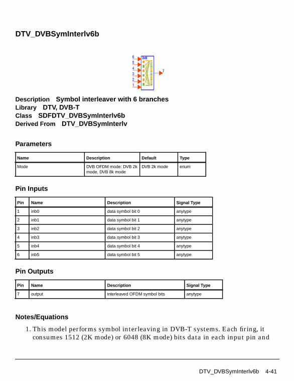
DTV_DVBSymInterlv6b
Description Symbol interleaver with 6 branchesLibrary DTV, DVB-TClass SDFDTV_DVBSymInterlv6bDerived From DTV_DVBSymInterlv
Parameters
Pin Inputs
Pin Outputs
Notes/Equations
1. This model performs symbol interleaving in DVB-T systems. Each firing, itconsumes 1512 (2K mode) or 6048 (8K mode) bits data in each input pin and
Name Description Default Type
Mode DVB OFDM mode: DVB 2kmode, DVB 8k mode
DVB 2k mode enum
Pin Name Description Signal Type
1 inb0 data symbol bit 0 anytype
2 inb1 data symbol bit 1 anytype
3 inb2 data symbol bit 2 anytype
4 inb3 data symbol bit 3 anytype
5 inb4 data symbol bit 4 anytype
6 inb5 data symbol bit 5 anytype
Pin Name Description Signal Type
7 output interleaved OFDM symbol bits anytype
DTV_DVBSymInterlv6b 4-41
DVB-T Components
outputs them after interleaving. The interleaving algorithm is the same as thatdescribed for DTV_DVBSymInterlv2b except for the input bit streams.
2. This model is one of the three symbol interleavers with data symbol bit inputs.2-, 4-, and 6-bit data symbol interleavers are used for QPSK, 16-QAM, and64-QAM, respectively, before constellation mapping; a complex symbolinterleaver is used after constellation mapping. These models use the samepermutation sequence.
References
[1]ETSI, Digital Video Broadcasting (DVB); Framing structure, channel codingand modulation for digital terrestrial television. EN300 744 v1.2.1, EuropeanTelecommunication Standard, July 1999.
4-42 DTV_DVBSymInterlv6b
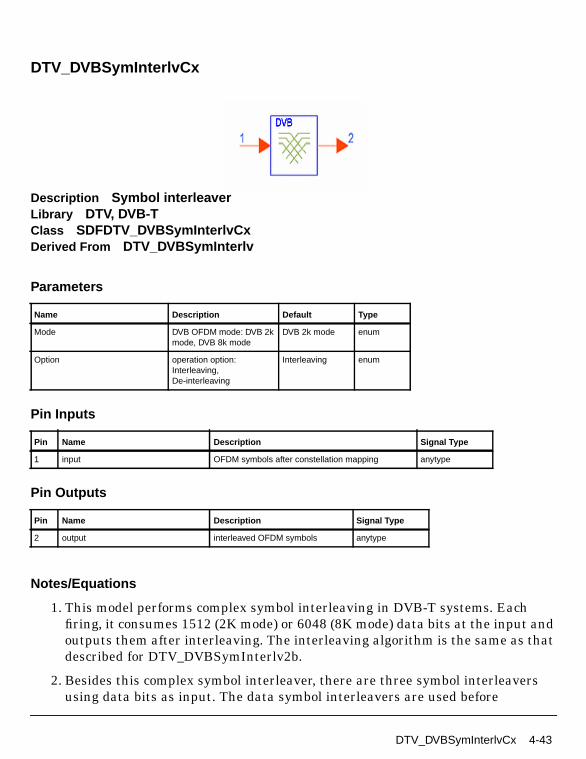
DTV_DVBSymInterlvCx
Description Symbol interleaverLibrary DTV, DVB-TClass SDFDTV_DVBSymInterlvCxDerived From DTV_DVBSymInterlv
Parameters
Pin Inputs
Pin Outputs
Notes/Equations
1. This model performs complex symbol interleaving in DVB-T systems. Eachfiring, it consumes 1512 (2K mode) or 6048 (8K mode) data bits at the input andoutputs them after interleaving. The interleaving algorithm is the same as thatdescribed for DTV_DVBSymInterlv2b.
2. Besides this complex symbol interleaver, there are three symbol interleaversusing data bits as input. The data symbol interleavers are used before
Name Description Default Type
Mode DVB OFDM mode: DVB 2kmode, DVB 8k mode
DVB 2k mode enum
Option operation option:Interleaving,De-interleaving
Interleaving enum
Pin Name Description Signal Type
1 input OFDM symbols after constellation mapping anytype
Pin Name Description Signal Type
2 output interleaved OFDM symbols anytype
DTV_DVBSymInterlvCx 4-43

DVB-T Components
constellation mapping; the complex symbol interleaver is used afterconstellation mapping. These models use the same permutation sequence.
References
[1]ETSI, Digital Video Broadcasting (DVB); Framing structure, channel codingand modulation for digital terrestrial television. EN300 744 v1.2.1, EuropeanTelecommunication Standard, July 1999.
4-44 DTV_DVBSymInterlvCx

DTV_DVBTHierInnerDeInterlv
Description Inner de-interleaver for 16QAM, 64QAM hierarchical transmissionmodesLibrary DTV, DVB-T
Parameters
Pin Inputs
Pin Outputs
Notes/Equations
1. This subnetwork model performs inner de-interleaving for 16QAM and 64QAMfor hierarchical transmission. 16QAM and 64QAM functions are performed byan if-else structure. The schematic for this subnetwork is shown in Figure 4-9.
Name Description Default Type
Mode transmission mode: DVB2k mode, DVB 8k mode
DVB 2k mode enum
MappingMode signal constellations andmapping: QAM-16,QAM-64
QAM-16 enum
Pin Name Description Signal Type
1 Symbols input of inner de-interleaver anytype
Pin Name Description Signal Type
2 HP_Bits The high priority bit stream for hierarchical modes anytype
3 LP_Bitstream The low priority bit stream for hierarchical modes anytype
DTV_DVBTHierInnerDeInterlv 4-45

DVB-T Components
Figure 4-9. DTV_DVBTHierInnerDeInterlv Subnetwork
2. The Mode parameter specifies the 2K or 8K mode.
3. The MappingMode parameter specifies QAM-16 or QAM-64.
References
[1]ETSI, Digital Video Broadcasting (DVB); Framing structure, channel codingand modulation for digital terrestrial television. EN300 744 v1.2.1, EuropeanTelecommunication Standard, July 1999.
4-46 DTV_DVBTHierInnerDeInterlv

DTV_DVBTHierInnerInterlv
Description Inner interleaver for 16QAM, 64QAM hierarchical transmission modeLibrary DTV, DVB-T
Parameters
Pin Inputs
Pin Outputs
Notes/Equations
1. This subnetwork model performs 16QAM and 64QAM inner interleaving forhierarchical transmission. 16QAM and 64QAM inner interleaver is integrated;functions are performed by an if-else structure. The schematic for thissubnetwork is shown in Figure 4-10.
Name Description Default Type
Mode transmission mode: DVB2k mode, DVB 8k mode
DVB 2k mode enum
MappingMode signal constellations andmapping: QAM-16,QAM-64
QAM-16 enum
Pin Name Description Signal Type
1 HP_Bits The high priority bit stream for hierarchical modes anytype
2 LP_Bits The low priority bit stream for hierarchical modes anytype
Pin Name Description Signal Type
3 Symbols output of inner interleaver anytype
DTV_DVBTHierInnerInterlv 4-47

DVB-T Components
Figure 4-10. DTV_DVBTHierInnerInterlv Schematic
2. The Mode parameter specifies the 2K or 8K mode.
3. The MappingMode parameter specifies QAM-16 or QAM-64.
References
[1]ETSI, Digital Video Broadcasting (DVB); Framing structure, channel codingand modulation for digital terrestrial television. EN300 744 v1.2.1, EuropeanTelecommunication Standard, July 1999.
4-48 DTV_DVBTHierInnerInterlv

DTV_DVBTHierReceiver
Description DVB-T hierarchical receiverLibrary DTV, DVB-T
Parameters
Pin Inputs
Name Description Default Sym Type Range
Mode transmission mode: DVB2k mode, DVB 8k mode
DVB 2k mode enum
OversamplingOption oversampling ratio option:Ratio 1, Ratio 2, Ratio 4,Ratio 8, Ratio 16, Ratio 32
Ratio 1 S enum
GuardInterval guard interval (frac FFTsize)
0.125 real [0, 1]
CodeRateHP high priority stream currentcode rate: HP 1/2, HP 2/3,HP 3/4, HP 5/6, HP 7/8
HP 1/2 enum
CodeRateLP low priority stream currentcode rate: LP 1/2, LP 2/3,LP 3/4, LP 5/6, LP 7/8
LP 1/2 enum
MappingMode signal consetllaions andmapping: QAM-16,QAM-64
QAM-16 enum
Alpha non-uniform factor forDVB-T.
1 int [1, ∞)
SoftDecision soft decision viterbidecoding type: Soft, Hard,Cochannel
Soft enum
TrunLen path memory truncationlength of Viterbi decodingalgorithm, in bytes
10 int [5, ∞)
Pin Name Description Signal Type
1 Rx_signal received OFDM signal to be demodulated complex
DTV_DVBTHierReceiver 4-49

DVB-T Components
Pin Outputs
Notes/Equations
1. This subnetwork model implements the DVB-T hierarchical receiver function.The schematic for this subnetwork is shown in Figure 4-11.
Figure 4-11. DTV_DVBTHierReceiver Schematic
Pin Name Description Signal Type
2 HPBytes_Decoded decoded bytes after Reed Solomon decoder withhigh priority
int
3 LPBytes_Decoded decoded bytes after Reed Solomon decoder with lowpriority
int
4 HPBytes_AfterViterbi decoded bytes after Viterbi decoder with high priority int
5 LPBytes_AfterViterbi decoded bytes after Viterbi decoder with low priority int
6 TPS_Bits decoded TPS information bits int
7 constellation constellation signal after OFDM demodulation complex
4-50 DTV_DVBTHierReceiver

2. Output Delays
The constellation pin has a delay of 8 OFDM symbols. The 8 × 1705 (2K mode)or 8 × 6817 (8K mode) constellation output signals are not used for EVMcalculation.
DTV_BCHDecoder uses a 68-bit block; so, a Delay component with N=60 isinserted before DTV_DVBTPSDemod. Pin TPS_Bits has one DVB-T frame (68OFDM symbols) delay; the first 53 bits at TPS_Bits are not used.
LPBytes_AfterViterbi and HPBytes_AfterViterbi each have 8 OFDM symboldelays.
The inner decoding (or convolutional decoding) is based on MPEG-2 transportMUX packet. So, the LPBytes_Decoded, HPBytes_Decoded,HPBytes_AfterViterbi, and LPBytes_AfterViterbi delays must be multiples ofcoded (204) and uncoded (188) transport MUX packet blocks.
The information bytes per one OFDM symbol in HPBytes_AfterViterbi iscalculated as follows:
DataPerOFDMSymbol=1512 (2K mode) or 6048 (8K mode)
CodedBlockSize=204
HPCodeRate = 1/2, 2/3, 3/4, 5/6 or 7/8
DelayOFDMSymbols = 8
HPInfoBytes = DelayOFDMSymbols×DataPerOFDMSymbol×HPCodeRate/8
The block delay of HPBytes_AfterViterbi is Delay_HPAfterViterbi andcalculated as follows:
HPDelayBytes=DelayOFDMSymbols×HPInfoBytes-(int(DelayOFDMSymbols×HPInfoBytes/CodedBlockSize))×CodedBlockSize
N_HP=int((TrunLen+LPDelayBytes)/CodedBlockSize)
Delay_HPAfterViterbi=1+int((DelayOFDMSymbols×HPInfoBytes)/CodedBlockSize)+N_HP.
Block size is 204 bytes.
The information bytes per one OFDM symbol in LPBytes_AfterViterbi iscalculated as follows:
DataPerOFDMSymbol=1512 (2K mode) or 6048 (8K mode)
DTV_DVBTHierReceiver 4-51

DVB-T Components
CodedBlockSize=204
BitsPerQAMmappingLP=2 for 16-QAM or 4 for 64-QAM,
LPCodeRate = 1/2, 2/3, 3/4, 5/6 or 7/8
LPInfoBytes=BitsPerQAMmappingLP×DataPerOFDMSymbol×LPCodeRate/8
The block delay of LPBytes_AfterViterbi is Delay_LPAfterViterbi is calculatedas follows:
LPDelayBytes=DelayOFDMSymbols×LPInfoBytes-(int(DelayOFDMSymbols×LPInfoBytes/CodedBlockSize))×CodedBlockSize,
N_LP=int((TrunLen+LPDelayBytes)/CodedBlockSize),
Delay_LPAfterViterbi=1+int((DelayOFDMSymbols×LPInfoBytes)/CodedBlockSize)+N_LP.
Block size is 204 bytes.
HPBytes_Decoded and LPBytes_Decoded each have 8 OFDM symbol and 11transport MUX packet delays.
The block delay of HPBytes_Decoded is:
Delay_HPDecoded=11+1+int((DelayOFDMSymbols×HPInfoBytes)/CodedBlockSize)+N_HP.
Block size is 188 bytes.
The block delay of LPBytes_Decoded is
Delay_LPDecoded=11+1+int((DelayOFDMSymbols×LPInfoBytes)/CodedBlockSize)+N_LP.
Block size is 188 bytes.
3. Receiver functions are implemented according to the DVB-T Standard.
Start of OFDM symbol is detected by the DTV_DVBTOFDMDemod subnetwork(shown in Figure 4-12).
4-52 DTV_DVBTHierReceiver

Figure 4-12. DTV_DVBTOFDMDemod Schematic
DTV_MLEstimator calculates the correlation based on guard interval;DTV_LoadFFTBuff selects the index with the maximum correlation value asthe start of FFT.
DTV_DVBCh2DEstimator estimates the complex channel impulse responsesfor continual and scattered pilot subcarriers. The channel impulse responses ofthe data subcarriers are 2D interpolated based on the estimated CIR.
Each subcarrier value is divided with a complex estimated channel responsecoefficient (phase tracking, phase synchronization, and equalization). Thissimple one-tap frequency domain channel response compensation isimplemented by DTV_OFDMEqualizer.
After equalization, DTV_DVBDemuxOFDMSym demultiplexes 1705 or 6817subcarriers into 1512 (2K mode) or 6048 (8K mode) data subcarriers and 1demodulated TPS.
The demodulated 1512 or 6048 data subcarriers (such as 16QAM, and 64QAMmodulation) are demapped by DTV_Demapper.
DTV_DVBTHierReceiver 4-53

DVB-T Components
The demodulated bits are deinterleaved by DTV_DVBTHierInnerDeinterlv anddivided into high- and low-priority demodulated bits. The demodulated bits areinner decoded (DTV_InnerDecoder), outer de-interleaved (DTV_InterlvInt),outer decoded (DTV_RSDecoder) and descrambled (DTV_ScrambleByte). Thefully-decoded high- and low-priority stream bytes are output asHPBytes_Decoded and LPBytes_Decoded.
After inner-decoding, the partially-decoded high- and low-priority stream bytesare output as HPBytes_AfterViterbi and LPBytes_AfterViterbi.
The TPS signal is demodulated by DTV_DVBTPSDemod; the demodulated bitsare decoded by DTV_BCHDecoder.
Output pins of this DTV_DVBTHierReceiver subnetwork correspond to those ofDTV_DVBTHierSignalSrc.
This hierarchical receiver works per one OFDM symbol. The number of samplesof each OFDM symbol (Rx_signal input pin) is:
• (1+GuardInterval)×2048×OversamplingRatio (2K mode)
• (1+GuardInterval)×8192×OversamplingRatio (8K mode)
The number of signals at the constellation output pin is 1705 (2K mode) or 6817(8K mode) per one OFDM symbol.
4. Parameter Details
Mode specifies the 2K or 8K transmission mode as defined in DVB-T.
OversamplingOption specifies the transmission signal oversampling ratio 1, 2,4, 8, 16, 32. If OversamplingOption=Ratio 2, the IFFT size is 4096 for 2K modeor 16384 for 8K mode.
GuardInterval specifies the guard interval (also called cyclic extension) lengthfor each symbol time, as a fraction of the FFT time period. Guard interval types1/4, 1/8, 1/16 and 1/32 are defined in the DVB-T specification. GuardIntervalcan be set to any value between 0.0 and 1.0 (not just 1/4, 1/8, 1/16 and 1/32). Forproper demodulation, the value must match the guard interval length actuallyused in the input signal.
CodeRateHP specifies the high-priority stream code rate: 1/2, 2/3, 3/4, 5/6 or 7/8.
CodeRateLP specifies the low-priority stream code rate: 1/2, 2/3, 3/4, 5/6 or 7/8.
MappingMode specifies signal constellation and mapping modes: 16-QAM or64-QAM.
4-54 DTV_DVBTHierReceiver
Alpha is used for signal constellation and mapping as defined in DVB-Tspecifications. If Alpha=1, 16-QAM or 64-QAM uniform mapping is performed;if Alpha=2 or 4, 16-QAM or 64-QAM in non-uniform mapping is performed.
SoftDecision specifies the Viterbi decoding algorithm mode.
• If SoftDecision=Soft, the Viterbi decoding algorithm is a soft decision decoderand uses channel status information.
• If SoftDecision=Hard, the Viterbi decoding algorithm is a hard decisiondecoder and does not use channel status information.
• If SoftDecision=Cochannel, the Viterbi decoding algorithm is for co-channelmeasurement with PAL analog TV and digital DVB-T.
TrunLen sets the truncation length (in bytes) in the Viterbi decoding algorithm.The path memory is 8×TrunLen bits in the Viterbi decoding algorithm.
References
[1]ETSI, Digital Video Broadcasting (DVB); Framing structure, channel codingand modulation for digital terrestrial television. EN300 744 v1.2.1, EuropeanTelecommunication Standard, July 1999.
[2] W.C.Lee, H.M.Park, K.J.Kang, K.B.Kim, “Performance Analysis of ViterbiDecoder Using Channel State Information in COFDM System” IEEETRANSACTIONS ON BROADCASTING, Vol.,44,NO.4, DECEMBER 1998.
DTV_DVBTHierReceiver 4-55

DVB-T Components
DTV_DVBTHierReceiver_RF
Description DVB-T RF hierarchical receiverLibrary DTV, DVB-T
Parameters
Name Description Default Sym Unit Type Range
RIn input resistance DefaultRIn Ohm real (0, ∞)
ROut output resistance DefaultROut Ohm real (0, ∞)
RTemp physical temperature, indegrees C
DefaultRTemp Celsius real [-273.15, ∞)
GainImbalance Gain imbalance, Q vs I 0.0 dB real (-∞, ∞)
PhaseImbalance Phase imbalance, Q vs I 0.0 deg real (-∞, ∞)
FCarrier carrier frequency 474.0MHz Hz real (0, ∞)
Sensitivity voltage output sensitivity,Vout/Vin
1 real (-∞, ∞)
Phase reference phase in degrees 0.0 deg real (-∞, ∞)
Mode transmission mode: DVB2k mode, DVB 8k mode
DVB 2k mode enum
OversamplingOption oversampling ratio option:Ratio 1, Ratio 2, Ratio 4,Ratio 8, Ratio 16, Ratio 32
Ratio 1 S enum
GuardInterval guard interval (frac FFTsize)
0.125 real [0, 1]
CodeRateHP high priority stream currentcode rate: HP 1/2, HP 2/3,HP 3/4, HP 5/6, HP 7/8
HP 1/2 enum
CodeRateLP low priority stream currentcode rate: LP 1/2, LP 2/3,LP 3/4, LP 5/6, LP 7/8
LP 1/2 enum
MappingMode signal consetllaions andmapping: QAM-16,QAM-64
QAM-16 enum
4-56 DTV_DVBTHierReceiver_RF

Pin Inputs
Pin Outputs
Notes/Equations
1. This subnetwork model implements the DVB-T RF hierarchical receiverfunction. The received RF signal is demodulated and fed to the basebandreceiver.
The schematic for this subnetwork is shown in Figure 4-13.
The baseband demodulator schematic is shown in Figure 4-14.
Alpha non-uniform factor forDVB-T.
1 int [1, ∞)
SoftDecision soft decision viterbidecoding type: Soft, Hard,Cochannel
Soft enum
TrunLen path memory truncationlength of Viterbi decodingalgorithm, in bytes
10 int [5, ∞)
Pin Name Description Signal Type
1 Rx_signal received OFDM signal to be demodulated timed
Pin Name Description Signal Type
2 HPBytes_Decoded decoded bytes after Reed Solomon decoder withhigh priority
int
3 LPBytes_Decoded decoded bytes after Reed Solomon decoder with lowpriority
int
4 HPBytes_AfterViterbi decoded bytes after Viterbi decoder with high priority int
5 LPBytes_AfterViterbi decoded bytes after Viterbi decoder with low priority int
6 TPS_Bits decoded TPS information bits int
7 constellation constellation signal after OFDM demodulation complex
Name Description Default Sym Unit Type Range
DTV_DVBTHierReceiver_RF 4-57

DVB-T Components
Figure 4-13. DTV_DVBTHierReceiver_RF schematic
Figure 4-14. DTV_DVBTHierReceiver Schematic
4-58 DTV_DVBTHierReceiver_RF

2. Output Delays
The constellation pin has a delay of 8 OFDM symbols. The first 8 × 1705 (2Kmode) or 8 × 6817 (8K mode) constellation output signals are not used for EVMcalculation.
DTV_BCHDecoder uses a 68-bit block; so, a Delay component with N=60 isinserted before DTV_DVBTPSDemod.
Pin TPS_Bits has one DVB-T frame (68 OFDM symbols) delay; the first 53 bitsat TPS_Bits are not used.
LPBytes_AfterViterbi and HPBytes_AfterViterbi each have 8 OFDM symboldelays.
Inner (or convolutional) decoding is based on an MPEG-2 transport MUXpacket. So, the LPBytes_Decoded, HPBytes_Decoded, HPBytes_AfterViterbi,and LPBytes_AfterViterbi delays must be multiples of coded (204) and uncoded(188) transport MUX packet blocks.
The information bytes for one OFDM symbol in HPBytes_AfterViterbi iscalculated as follows:
DataPerOFDMSymbol=1512 (2K mode) or 6048 (8K mode)
CodedBlockSize=204
HPCodeRate = 1/2, 2/3, 3/4, 5/6 or 7/8
DelayOFDMSymbols = 8
HPInfoBytes=DelayOFDMSymbols×DataPerOFDMSymbol×HPCodeRate/8
The block delay of HPBytes_AfterViterbi is Delay_HPAfterViterbi andcalculated as follows:
HPDelayBytes=DelayOFDMSymbols×HPInfoBytes-(int(DelayOFDMSymbols×HPInfoBytes/CodedBlockSize))×CodedBlockSize
N_HP=int((TrunLen+LPDelayBytes)/CodedBlockSize)
Delay_HPAfterViterbi=1+int((DelayOFDMSymbols×HPInfoBytes)/CodedBlockSize)+N_HP.
Block size is 204 bytes.
The information bytes for one OFDM symbol in LPBytes_AfterViterbi iscalculated as follows:
DTV_DVBTHierReceiver_RF 4-59

DVB-T Components
DataPerOFDMSymbol=1512 (2K mode) or 6048 (8K mode)
CodedBlockSize=204
BitsPerQAMmappingLP=2 for 16-QAM or 4 for 64-QAM,
LPCodeRate = 1/2, 2/3, 3/4, 5/6 or 7/8
LPInfoBytes=BitsPerQAMmappingLP×DataPerOFDMSymbol×LPCodeRate/8
The block delay of LPBytes_AfterViterbi is Delay_LPAfterViterbi is calculatedas follows:
LPDelayBytes=DelayOFDMSymbols×LPInfoBytes-(int(DelayOFDMSymbols×LPInfoBytes/CodedBlockSize))×CodedBlockSize,
N_LP=int((TrunLen+LPDelayBytes)/CodedBlockSize),
Delay_LPAfterViterbi=1+int((DelayOFDMSymbols×LPInfoBytes)/CodedBlockSize)+N_LP.
Block size is 204 bytes.
HPBytes_Decoded and LPBytes_Decoded each have 8 OFDM symbols and 11transport MUX packet delays.
The block delay of HPBytes_Decoded is:
Delay_HPDecoded=11+1+int((DelayOFDMSymbols×HPInfoBytes)/CodedBlockSize)+N_HP.
Block size is 188 bytes.
The block delay of LPBytes_Decoded is
Delay_LPDecoded=11+1+int((DelayOFDMSymbols×LPInfoBytes)/CodedBlockSize)+N_LP.
Block size is 188 bytes.
4-60 DTV_DVBTHierReceiver_RF

3. Receiver functions are implemented according to the DVB-T Standard.
Start of OFDM symbol is detected by the DTV_DVBTOFDMDemod subnetwork(Figure 4-15).
Figure 4-15. DTV_DVBTOFDMDemod Schematic
DTV_MLEstimator calculates the correlation based on guard interval;DTV_LoadFFTBuff selects the index with the maximum correlation value asthe start of FFT.
DTV_DVBCh2DEstimator estimates the complex channel impulse responsesfor continual and scattered pilot subcarriers. Channel impulse responses of thedata subcarriers are 2D interpolated based on the estimated CIR.
Each subcarrier value is divided with a complex estimated channel responsecoefficient (phase tracking, phase synchronization, and equalization). Thissimple one-tap frequency domain channel response compensation isimplemented by DTV_OFDMEqualizer.
DTV_DVBTHierReceiver_RF 4-61

DVB-T Components
After equalization, DTV_DVBDemuxOFDMSym demultiplexes 1705 or 6817subcarriers into 1512 (2K mode) or 6048 (8K mode) data subcarriers and 1demodulated TPS.
The demodulated 1512 or 6048 data subcarriers (16QAM, and 64QAMmodulation) are demapped by DTV_Demapper.
The demodulated bits are deinterleaved by DTV_DVBTHierInnerDeinterlv anddivided into high- and low-priority demodulated bits. The demodulated bits areinner decoded (DTV_InnerDecoder), outer de-interleaved (DTV_InterlvInt),outer decoded (DTV_RSDecoder) and descrambled (DTV_ScrambleByte). Thefully-decoded high- and low-priority stream bytes are output asHPBytes_Decoded and LPBytes_Decoded.
After inner-decoding, the partially-decoded high- and low-priority stream bytesare output as HPBytes_AfterViterbi and LPBytes_AfterViterbi.
The TPS signal is demodulated by DTV_DVBTPSDemod; the demodulated bitsare decoded by DTV_BCHDecoder.
Output pins of this DTV_DVBTHierReceiver subnetwork correspond to those ofDTV_DVBTHierSignalSrc.
This hierarchical receiver works uses one OFDM symbol. The number ofsamples of each OFDM symbol (Rx_signal input pin) is:
• (1+GuardInterval)×2048×OversamplingRatio for 2K mode
• (1+GuardInterval)×8192×OversamplingRatio for 8K mode
The number of signals at the constellation output pin is 1705 (2K mode) or 6817(8K mode) for one OFDM symbol.
4. Parameter Details
GainImbalance and PhaseImbalance add certain impairments to the idealoutput RF signal. Impairments are added in the order described here.
The unimpaired RF I and Q envelope voltages have gain and phase imbalanceapplied. The RF is given by:
where V1(t) is the in-phase RF envelope, V2(t) is the quadrature phase RFenvelope, g is the gain imbalance
V3 t( ) A V1 t( ) ωct( )cos gV2 t( ) ωctφπ180---------+
sin– =
4-62 DTV_DVBTHierReceiver_RF

and, φ (in degrees) is the phase imbalance.
Mode specifies the 2K or 8K transmission mode as defined in DVB-T.
OversamplingOption specifies the transmission signal oversampling ratio 1, 2,4, 8, 16, 32. If OversamplingOption=Ratio 2, the IFFT size is 4096 for 2K modeor 16384 for 8K mode.
GuardInterval specifies the guard interval (also called cyclic extension) lengthfor each symbol time, as a fraction of the FFT time period. Guard interval types1/4, 1/8, 1/16 and 1/32 are defined in the DVB-T specification. GuardIntervalcan be set to any value between 0.0 and 1.0 (not just 1/4, 1/8, 1/16 and 1/32). Forproper demodulation, the value must match the guard interval length actuallyused in the input signal.
CodeRateHP specifies the high-priority stream code rate: 1/2, 2/3, 3/4, 5/6 or 7/8.
CodeRateLP specifies the low-priority stream code rate: 1/2, 2/3, 3/4, 5/6 or 7/8.
MappingMode specifies signal constellations and mapping for the DVB-Thierarchical signal source. Mapping modes 16-QAM and 64-QAM are available.
Alpha is used for signal constellation and mapping as defined in DVB-Tspecifications. If Alpha=1, 16-QAM or 64-QAM uniform mapping is performed;if Alpha=2 or 4, 16-QAM or 64-QAM in non-uniform mapping is performed.
SoftDecision specifies the Viterbi decoding algorithm mode.
• If SoftDecision=Soft, the Viterbi decoding algorithm is a soft decision decoderand uses channel status information.
• If SoftDecision=Hard, the Viterbi decoding algorithm is a hard decisiondecoder and does not use channel status information.
• If SoftDecision=Cochannel, the Viterbi decoding algorithm is for co-channelmeasurement with PAL analog TV and digital DVB-T.
TrunLen sets the truncation length (in bytes) in the Viterbi decoding algorithm.The path memory is 8×TrunLen bits in Viterbi decoding algorithm.
g 10
GainImbalance20
-----------------------------------------------
=
DTV_DVBTHierReceiver_RF 4-63

DVB-T Components
References
[1]ETSI, Digital Video Broadcasting (DVB); Framing structure, channel codingand modulation for digital terrestrial television. EN300 744 v1.2.1, EuropeanTelecommunication Standard, July 1999.
[2] W.C.Lee, H.M.Park, K.J.Kang, K.B.Kim, “Performance Analysis of ViterbiDecoder Using Channel State Information in COFDM System” IEEETRANSACTIONS ON BROADCASTING, Vol.,44,NO.4, DECEMBER 1998.
4-64 DTV_DVBTHierReceiver_RF

DTV_DVBTHierSignalSrc
Description DVB-T hierarchical signal sourceLibrary DTV, DVB-T
Parameters
Name Description Default Sym Type Range
Mode transmission mode: DVB2k mode, DVB 8k mode
DVB 2k mode enum
OversamplingOption oversampling ratio option:Ratio 1, Ratio 2, Ratio 4,Ratio 8, Ratio 16, Ratio 32
Ratio 1 S enum
GuardInterval guard interval (frac FFTsize)
0.125 real [0, 1]
CodeRateHP high priority stream currentcode rate: HP 1/2, HP 2/3,HP 3/4, HP 5/6, HP 7/8
HP 1/2 enum
CodeRateLP low priority stream currentcode rate: LP 1/2, LP 2/3,LP 3/4, LP 5/6, LP 7/8
LP 1/2 enum
MappingMode signal consetllaions andmapping: QAM-16,QAM-64
QAM-16 enum
Alpha non-uniform factor forDVB-T.
1 int [1, ∞)
DataTypeHP Payload data type with highpriority: PN9 HP, PN15 HP,FIX4 HP, _4_1_4_0 HP,_8_1_8_0 HP, _16_1_16_0HP, _32_1_32_0 HP,_64_1_64_0 HP
PN9 HP enum
DataTypeLP Payload data type with lowpriority: PN9 LP, PN15 LP,FIX4 LP, _4_1_4_0 LP,_8_1_8_0 LP, _16_1_16_0LP, _32_1_32_0 LP,_64_1_64_0 LP
PN15 LP enum
DTV_DVBTHierSignalSrc 4-65

DVB-T Components
Pin Outputs
Notes/Equations
1. This subnetwork model is used to generate the DVB-T hierarchical signalsource. Each firing, one OFDM symbol is generated.
The schematic for this subnetwork is shown in Figure 4-16.
Figure 4-16. DTV_DVBTHierSignalSrc Schematic
Pin Name Description Signal Type
1 DVBT_signal DVB-T signal complex
2 HPBytes_Uncoded information bytes of transport packet with highpriority
int
3 LPBytes_Uncoded information bytes of transport packet with low priority int
4 HPBytes_BeforeCC information bytes before convolutional coder withhigh priority
int
5 LPBytes_BeforeCC information bytes before convolutional coder with lowpriority
int
6 TPS_Bits TPS information bits int
7 constellation constellation signal before IFFT complex
4-66 DTV_DVBTHierSignalSrc

Note To use the 8 transport MUX packet structure according to the DVB-Tstandard, HP_stream and LP_stream with 8 transport MUX packets can bemade active (HP_stream1, LP_stream1, B2 and B3 must be made inactive).However, the signal source with 8 transport MUX packets will consume muchmore memory during simulation.
2. The format of the hierarchical signal source follows the DVB-T specification.Figure 4-17 is functional block diagram of the DVB-T baseband system.
The DTV_DVBTHierSignalSrc includes: scrambler (DTV_ScrambleByte); outercoder (DTV_RSCoder); outer interleaver (DTV_InterlvInt); inner coder(DTV_PuncConvCoder); inner interleaver (DTV_DVBTHierInnerInterlv);mapper (DTV_Mapper); and, frame adaptation, OFDM, and guard intervalinsertion (in DTV_DVBTOFDMMod subnetwork).
Figure 4-17. DVB-T Baseband System Functional Block Diagram
This hierarchical signal source works per one OFDM symbol: 1705 (2K mode) or6817 (8K mode) constellations are output. The number of samples for eachOFDM symbol (DVBT_signal output pin) is:
• (1+GuardInterval)×2048×OversamplingRatio (2K mode)
• (1+GuardInterval)×8192×OversamplingRatio (8K mode)
MUXAdaptation
EnergyDispersal
OuterCoder
OuterInterleaver
InnerCoder
InnerInterleaver Mapper
FrameAdaptation OFDM
GuardInterval
Insertion
MUXAdaptation
EnergyDispersal
OuterCoder
OuterInterleaver
InnerCoder
Pilot andTPS
Signals
DTV_DVBTHierSignalSrc 4-67

DVB-T Components
3. Parameter Details
Mode specifies the 2K or 8K transmission mode as defined in the DVB-Tspecification.
OversamplingOption specifies the transmission signal oversampling ratio 1, 2,4, 8, 16, 32. If OversamplingOption=2, the IFFT size is 4096 (2K mode) or 16384(8K mode).
GuardInterval specifies the guard interval (also called cyclic extension) lengthfor each symbol time, as a fraction of the FFT time period. Guard interval types1/4, 1/8, 1/16 and 1/32 are defined in the DVB-T specification. GuardIntervalcan be set to any value between 0.0 and 1.0 (not just 1/4, 1/8, 1/16 and 1/32). Forproper demodulation, the value must match the guard interval length actuallyused in the input signal.
CodeRateHP specifies the high priority stream code rate: 1/2, 2/3, 3/4, 5/6 or 7/8.
CodeRateLP specifies the low priority stream code rate: 1/2, 2/3, 3/4, 5/6 or 7/8.
MappingMode specifies the DVB-T hierarchical signal source constellations:16-QAM or 64-QAM.
Alpha is used for signal constellation and mapping (based on MappingMode).
• If Alpha=1, uniform mapping of 16-QAM or 64-QAM is used.
• If Alpha=2 or 4, non-uniform mapping of 16-QAM or 64-QAM is used asdefined in DVB-T specification.
For the DataTypeHP parameter:
• if PN9 HP is selected, a 511-bit pseudo-random test pattern is generatedaccording to CCITT Recommendation O.153
• if PN15 HP is selected, a 32767-bit pseudo-random test pattern is generatedaccording to CCITT Recommendation O.151
• if FIX4 HP is selected, a zero-stream is generated
• if x_1_x_0 HP is selected (x equals 4, 8, 16, 32, or 64) a periodic bit stream isgenerated, with the period being 2x. In one period, the first x bits are 1s andthe second x bits are 0s.
4-68 DTV_DVBTHierSignalSrc

For the DataTypeLP parameter:
• if PN9 LP is selected, a 511-bit pseudo-random test pattern is generatedaccording to CCITT Recommendation O.153
• if PN15 LP is selected, a 32767-bit pseudo-random test pattern is generatedaccording to CCITT Recommendation O.151
• if FIX4 LP is selected, a zero-stream is generated
• if x_1_x_0 is selected (x equals 4, 8, 16, 32, or 64) a periodic bit stream isgenerated, with the period being 2x. In one period, the first x bits are 1s andthe second x bits are 0s.
References
[1]ETSI, Digital Video Broadcasting (DVB); Framing structure, channel codingand modulation for digital terrestrial television. EN300 744 v1.2.1, EuropeanTelecommunication Standard, July 1999.
DTV_DVBTHierSignalSrc 4-69

DVB-T Components
DTV_DVBTHierSignalSrc_RF
Description DVB-T RF hierarchical signal sourceLibrary DTV, DVB-T
Parameters
Name Description Default Sym Unit Type Range
ROut output resistance DefaultROut Ohm real (0, ∞)
RTemp physical temperature, indegrees C
DefaultRTemp Celsius real [-273.15, ∞)
Noise Enable thermal noise? NO,YES
NO enum
FCarrier carrier frequency 474.0MHz Hz real (0, ∞)
Power modulator output power 40mW W real (0, ∞)
Bandwidth bandwidth (2048/224.0)MHz Hz real (0, ∞)
MirrorSpectrum Mirror spectrum aboutcarrier? NO, YES
NO enum
GainImbalance Gain imbalance, Q vs I 0.0 dB real (-∞, ∞)
PhaseImbalance Phase imbalance, Q vs I 0.0 deg real (-∞, ∞)
I_OriginOffset I origin offset (percent) 0.0 real (-∞, ∞)
Q_OriginOffset Q origin offset (percent) 0.0 real (-∞, ∞)
IQ_Rotation IQ rotation 0.0 deg real (-∞, ∞)
Mode transmission mode: DVB2k mode, DVB 8k mode
DVB 2k mode enum
OversamplingOption oversampling ratio option:Ratio 1, Ratio 2, Ratio 4,Ratio 8, Ratio 16, Ratio 32
Ratio 1 S enum
GuardInterval guard interval (frac FFTsize)
0.125 real [0, 1]
4-70 DTV_DVBTHierSignalSrc_RF

Pin Outputs
Notes/Equations
1. This subnetwork model integrates an RF modulator and a basebandhierarchical signal source based on the DVB-T specification. The baseband
CodeRateHP high priority stream currentcode rate: HP 1/2, HP 2/3,HP 3/4, HP 5/6, HP 7/8
HP 1/2 enum
CodeRateLP low priority stream currentcode rate: LP 1/2, LP 2/3,LP 3/4, LP 5/6, LP 7/8
LP 1/2 enum
MappingMode signal consetllaions andmapping: QAM-16,QAM-64
QAM-16 enum
Alpha non-uniform factor forDVB-T.
1 int [1, ∞)
DataTypeHP Payload data type with highpriority: PN9 HP, PN15 HP,FIX4 HP, _4_1_4_0 HP,_8_1_8_0 HP, _16_1_16_0HP, _32_1_32_0 HP,_64_1_64_0 HP
PN9 HP enum
DataTypeLP Payload data type with lowpriority: PN9 LP, PN15 LP,FIX4 LP, _4_1_4_0 LP,_8_1_8_0 LP, _16_1_16_0LP, _32_1_32_0 LP,_64_1_64_0 LP
PN15 LP enum
Pin Name Description Signal Type
1 RF_signal RF signal timed
2 DVBT_signal DVB-T signal complex
3 HPBytes_Uncoded information bytes of transport packet with highpriority
int
4 LPBytes_Uncoded information bytes of transport packet with low priority int
5 HPBytes_BeforeCC information bytes before convolutional coder withhigh priority
int
6 LPBytes_BeforeCC information bytes before convolutional coder with lowpriority
int
7 TPS_Bits TPS information bits int
8 constellation constellation signal before IFFT complex
Name Description Default Sym Unit Type Range
DTV_DVBTHierSignalSrc_RF 4-71

DVB-T Components
hierarchical signal is fed to the RF modulator; after RF modulation the timedsignal is output.
The schematic for this subnetwork is shown in Figure 4-18.
Figure 4-18. DTV_DVBTHierSignalSrc_RF Schematic
2. The format of DVB-T signal source follows the DVB-T specification. Figure 4-19is a functional block diagram of a DVB-T baseband system.
Figure 4-19. DVB-T Baseband System Block Diagram
3. The schematic for the hierarchical signal source is shown in Figure 4-20. TheDTV_DVBTHierSignalSrc includes: scrambler (DTV_ScrambleByte); outercoder (DTV_RSCoder); outer interleaver (DTV_InterlvInt); inner coder(DTV_PuncConvCoder); inner interleaver (DTV_DVBTHierInnerInterlv);mapper (DTV_Mapper); and, frame adaptation, OFDM, and guard intervalinsertion (in DTV_DVBTOFDMMod subnetwork).
MUXAdaptation
EnergyDispersal
OuterCoder
OuterInterleaver
InnerCoder
InnerInterleaver Mapper
FrameAdaptation OFDM
GuardInterval
Insertion
MUXAdaptation
EnergyDispersal
OuterCoder
OuterInterleaver
InnerCoder
Pilot andTPS
Signals
4-72 DTV_DVBTHierSignalSrc_RF

Note To use the 8 transport MUX packet structure, HP_stream andLP_stream with 8 transport MUX packets must be active, and HP_stream1,LP_stream1, B2, and B3 must be inactive. A signal source with 8 transportMUX packets will consume more memory during simulation.
Figure 4-20. DTV_DVBTHierSignalSrc Schematic
This hierarchical signal source works per each OFDM symbol: 1705 (2K mode)or 6817 (8K mode) constellations are output. DVBT_signal pin outputs samplesfor each OFDM symbol:
• (1+GuardInterval)×2048×OversamplingRatio (2K mode)
• (1+GuardInterval)×8192×OversamplingRatio (8K mode)
DTV_DVBTHierSignalSrc_RF 4-73

DVB-T Components
4. Parameter Details
FCarrier defines the RF frequency for the DVB signal.
Power defines the power level for FCarrier.
Bandwidth indicates signal band width.
MirrorSpectrum (when set to YES) conjugates the input signal before any otherprocessing is done.
The GainImbalance, PhaseImbalance, I_OriginOffset, Q_OriginOffset, andIQ_Rotation parameters add certain impairments to the ideal output RF signal.Impairments are added in the order described here.
The unimpaired RF I and Q envelope voltages have gain and phase imbalanceapplied. The RF is given by:
where A is a scaling factor that depends on the Power and ROut parametersspecified by the user, V1(t) is the in-phase RF envelope, V2(t) is the quadraturephase RF envelope, g is the gain imbalance
and, φ (in degrees) is the phase imbalance.
The signal V3(t) is rotated by IQ_Rotation degrees; I_OriginOffset andQ_OriginOffset are then applied to the rotated signal. Note that the amountsspecified are percentages with respect to the output rms voltage. The outputrms voltage is given by sqrt(2×ROut×Power).
Mode specifies the 2K or 8K transmission mode as defined in the DVB-Tspecification.
OversamplingOption specifies the transmission signal oversampling ratio 1, 2,4, 8, 16, 32. If OversamplingOption=2, the IFFT size is 4096 (2K mode) or 16384(8K mode).
GuardInterval specifies the guard interval (also called cyclic extension) lengthfor each symbol time, as a fraction of the FFT time period. Guard interval types1/4, 1/8, 1/16 and 1/32 are defined in the DVB-T specification. GuardIntervalcan be set to any value between 0.0 and 1.0 (not just 1/4, 1/8, 1/16 and 1/32). For
V3 t( ) A V1 t( ) ωct( )cos gV2 t( ) ωctφπ180---------+
sin– =
g 10
GainImbalance20
-----------------------------------------------
=
4-74 DTV_DVBTHierSignalSrc_RF
proper demodulation, the value must match the guard interval length actuallyused in the input signal.
CodeRateHP specifies the high priority stream code rate: 1/2, 2/3, 3/4, 5/6 or 7/8.
CodeRateLP specifies the low priority stream code rate: 1/2, 2/3, 3/4, 5/6 or 7/8.
MappingMode specifies signal constellation and mapping modes: 16-QAM or64-QAM.
Alpha is used for signal constellation and mapping as defined in DVB-Tspecifications. If Alpha=1, 16-QAM or 64-QAM uniform mapping is performed;if Alpha=2 or 4, 16-QAM or 64-QAM in non-uniform mapping is performed.
For the DataTypeHP parameter:
• if PN9 is selected, a 511-bit pseudo-random test pattern is generatedaccording to CCITT Recommendation O.153.
• if PN15 is selected, a 32767-bit pseudo-random test pattern is generatedaccording to CCITT Recommendation O.151.
• if FIX4 is selected, a zero-stream is generated.
• if x_1_x_0 is selected, where x equals 4, 8, 16, 32, or 64, a periodic bit streamis generated, with the period being 2x. In one period, the first x bits are 1sand the second x bits are 0s.
For the DataTypeLP parameter:
• if PN9 is selected, a 511-bit pseudo-random test pattern is generatedaccording to CCITT Recommendation O.153.
• if PN15 is selected, a 32767-bit pseudo-random test pattern is generatedaccording to CCITT Recommendation O.151.
• if FIX4 is selected, a zero-stream is generated.
• if x_1_x_0 is selected, where x equals 4, 8, 16, 32, or 64, a periodic bit streamis generated, with the period being 2x. In one period, the first x bits are 1sand the second x bits are 0s.
References
[1]ETSI, Digital Video Broadcasting (DVB); Framing structure, channel codingand modulation for digital terrestrial television. EN300 744 v1.2.1, EuropeanTelecommunication Standard, July 1999.
DTV_DVBTHierSignalSrc_RF 4-75

DVB-T Components
DTV_DVBTImpulseNoise
Description Impulse interference NoiseLibrary DTV, DVB-T
Parameters
Pin Outputs
Notes/Equations
1. This model generates an impulse interference typically caused by automotiveignition systems, domestic appliance switches, and electric motors. The impulseinterference consists of a number of bursts that are generated by gating aGaussian noise source of power P.
The schematic for this impulse noise generator is shown in Figure 4-21.
Name Description Default Unit Type Range
Test_No test mode: Test_No_1,Test_No_2, Test_No_3,Test_No_4, Test_No_5,Test_No_6
Test_No_3 enum
NoisePower power of impulseinterference noise
1.0W W real (-∞, ∞)
TStep time step 0.19375usec sec real (0, ∞)
FCarrier carrier frequency 474.0MHz Hz real (0, ∞)
RefR resistance 50Ohm Ohm real (0, ∞)
Pin Name Description Signal Type
1 Impulse_Interfence impulse interference noise timed
4-76 DTV_DVBTImpulseNoise

Figure 4-21. DTV_DVBTImpulseNoise Schematic
2. The impulse noise test signal is shown in Figure 4-22. From Figure 4-22, theseparation of bursts is fixed at 10 msec and pulse duration is fixed at 250 nsec.
Figure 4-22. Impulse Noise Test Signal
Note This model supports fixed spacing between pulses instead of variablespacing described in 11.13.3 of Ref. [1]. Fixed spacing is dependent on test typesdetailed in note 3.
DTV_DVBTImpulseNoise 4-77

DVB-T Components
3. This model supports 6 tests in which the number of pulses per burst and pulsespacing vary according to Test_No as listed in Table 4-12.
Noise power is the Gaussian noise power that is gated by pulses. It can bemeasured by closing the Rect pulse generators R1, R2, R3 in Figure 4-21.
References
[1]DTG RF Sub-Group Document No.67, chapter 11.
Table 4-12. Impulse Noise Tests and Pulse Parameters
Test_No
PulsesperBurst
PulseSpacing(usec)
BurstDuration(usec)
1 1 0.25 0.25
2 2 20 40
3 4 20 80
4 12 12 144
5 20 1.5 30
6 40 0.75 30
4-78 DTV_DVBTImpulseNoise

DTV_DVBTInnerDeInterlv
Description Inner de-interleaver for QPSK, 16QAM and 64QAM non-hierarchicaltransmission modesLibrary DTV, DVB-T
Parameters
Pin Inputs
Pin Outputs
Notes/Equations
1. This subnetwork model performs inner de-interleaving QPSK, 16QAM and64QAM non-hierarchical transmission modes. Functions are performed by anif-else structure.
The schematic for this subnetwork is shown in Figure 4-23.
Name Description Default Type
Mode transmission mode: DVB2k mode, DVB 8k mode
DVB 2k mode enum
MappingMode signal constellations andmapping: QPSK, QAM-16,QAM-64
QAM-16 enum
Pin Name Description Signal Type
1 Symbols input of inner de-interleaver anytype
Pin Name Description Signal Type
2 Bits output bit stream of inner de-interleaver anytype
DTV_DVBTInnerDeInterlv 4-79

DVB-T Components
Figure 4-23. DTV_DVBTInnerDeInterlv Subnetwork
2. The Mode parameter is used to specify the 2K mode or the 8K mode.
3. The MappingMode parameter is used to specify QPSK, QAM-16 or QAM-64.
References
[1]ETSI, Digital Video Broadcasting (DVB); Framing structure, channel codingand modulation for digital terrestrial television. EN300 744 v1.2.1, EuropeanTelecommunication Standard, July 1999.
4-80 DTV_DVBTInnerDeInterlv

DTV_DVBTInnerInterlv
Description Inner interleaver for QPSK, 16QAM, 64QAM non-hierarchicaltransmission modesLibrary DTV, DVB-T
Parameters
Pin Inputs
Pin Outputs
Notes/Equations
1. This subnetwork model performs inner interleaving QPSK, 16QAM and64QAM. Functions are performed by an if-else structure.
The schematic for this subnetwork is shown in Figure 4-24.
Name Description Default Type
Mode transmission mode: DVB2k mode, DVB 8k mode
DVB 2k mode enum
MappingMode signal constellations andmapping: QPSK, QAM-16,QAM-64
QAM-16 enum
Pin Name Description Signal Type
1 Bits Bit stream prior to inner interleaver anytype
Pin Name Description Signal Type
2 Symbols output of inner interleaver anytype
DTV_DVBTInnerInterlv 4-81

DVB-T Components
Figure 4-24. DTV_DVBTInnerInterlv Schematic
2. The Mode parameter is used to specify the 2K mode or the 8K mode.
3. The MappingMode parameter is used to specify QPSK, QAM-16 or QAM-64.
References
[1]ETSI, Digital Video Broadcasting (DVB); Framing structure, channel codingand modulation for digital terrestrial television. EN300 744 v1.2.1, EuropeanTelecommunication Standard, July 1999.
4-82 DTV_DVBTInnerInterlv

DTV_DVBTOFDMDemod
Description DVB-T OFDM de-modulatorLibrary DTV, DVB-T
Parameters
Pin Inputs
Pin Outputs
Notes/Equations
1. This subnetwork model implements OFDM demodulation for DVB-T.
The schematic for this subnetwork is shown in Figure 4-25.
Name Description Default Sym Type Range
Mode transmission mode: DVB2k mode, DVB 8k mode,DVB 4k mode
DVB 2k mode enum
OversamplingOption oversampling ratio option:Ratio 1, Ratio 2, Ratio 4,Ratio 8, Ratio 16, Ratio 32
Ratio 1 S enum
GuardInterval guard interval (frac FFTsize)
1/32 real [0, 1]
Pin Name Description Signal Type
1 input received OFDM symbol complex
Pin Name Description Signal Type
2 data information on data subcarriers complex
3 TPS information on TPS subcarriers complex
4 CIR estimated channel impulse response on datasubcarriers
complex
5 Constellation demodulated constellation on all active subcarriers complex
DTV_DVBTOFDMDemod 4-83

DVB-T Components
Figure 4-25. DTV_DVBTOFDMDemod Schematic
2. The data, TPS, and constellation output pins correspond toDTV_DVBTOFDMMod pins; the CIR pin outputs the estimated channelimpulse response of each data subcarrier, which is used as channel statusinformation in the soft Viterbi decoding algorithm.
Each firing, the input pin consumes(1+GuardInterval)×2048×OversamplingRatio of 2K mode,(1+GuardInterval)×4096×OversamplingRatio of 4K mode, or(1+GuardInterval)×8192×OversamplingRatio of 8K mode tokens. The data andCIR pins output 1512 (2K mode), 3024 (4K mode), or 6048 (8K mode) complexsignals; the constellation pin outputs 1705 (2K mode), 3049 (4K mode), or 6817(8K mode) demodulated complex signals; the TPS pin outputs one received TPSsignal.
DTV_DVBTOFDMDemod has a delay of 8 OFDM symbols when the receivedOFDM signal is demodulated; so, the output tokens for the first 8 OFDMsymbols in each output pin should be discarded.
3. De-multiplex demodulated subcarriers into TPS, data, and pilots (continual andscattered).
4-84 DTV_DVBTOFDMDemod

Figure 4-26 shows the frame structure. IntState of Length determines thenumber of CP (continual pilot) and TPS in each symbol; CP and TPS positionsare determined according to Table 4-13 and Table 4-14, respectively.
PRBS sequences in each segment are generated according to Figure 4-27; theinitial PRBS register setting is 11111111111. The PRBS in initialized so thatthe first output bit from the PRBS coincides with the first active carrier. A newvalue is generated by the PRBS on each carrier in each segment (whether or notit is a pilot).
Positions of the corresponding scattered pilots are generated as follows. For thesymbol of index l (ranging from 0 to 67), carriers for which index k belongs tosubset
are scattered pilots positions.
where p is an integer that takes all possible values 0, provided the resultingvalue for k does not exceed the valid range [Kmin, Kmax]; Kmin=0, andKmax=1705 (2K mode), Kmax=3409 (4K mode), or 6817 (8K mode). SPperiod,SPstart, SPoffset, and SPphase parameters control the scattered pilotspositions.
After determining the CP, TPS, and SP positions in each symbol and the valueof the PRBS sequence in all active carriers in the symbol, this subnetworkdemultiplexes input data into TPS and TSP data. According to the TPS positionand the PRBS sequence, one transmitted TPS bit is determined by the meanvalue of the TPS positions.
where NTPS is the number of TPS in one symbol; PilotValue is the PRBSsequence in symbol; x[i] is the input data.
The other positions (other than TPS, CP, and SP) in one segment are the TSPdata positions.
k Kmin 3+ l mod 4× 12p+= p integer p 0 k Kmin Kmax[ , ]∈,≥,
TPS 1NTPS------------------ x TPSposition l[ ][ ]
PilotValue TPSposition l[ ][ ]----------------------------------------------------------------------------------
l 1=
NTPS
∑=
Data i[ ] x i[ ]=
DTV_DVBTOFDMDemod 4-85

DVB-T Components
Figure 4-26. Frame Structure
Table 4-13. Carrier Indices for Continual Pilot Carriers
Continual pilot carrier positions (index number k)
2K mode 4K mode 8K mode
0 48 54 87 141 156 192 201 255 279 282333 432 450 483 525 531 618 636 714 759765 780 804 873 888 918 939 942 969 9841050 1101 1107 1110 1137 1140 1146 12061269 1323 1377 1491 1683 1704
0 48 54 87 141 156 192 201 255 279 282333 432 450 483 525 531 618 636 714 759765 780 804 873 888 918 939 942 969 9841050 1101 1107 1110 1137 1140 1146 12061269 1323 1377 1491 1683 1704 1752 17581791 1845 1860 1896 1905 1959 1983 19862037 2136 2154 2187 2229 2235 2322 23402418 2463 2469 2484 2508 2577 2592 26222643 2646 2673 2688 2754 2805 2811 281428412844 2850 2910 2973 3027 3081 31953387 3408
0 48 54 87 141 156 192 201 255 279 282333 432 450 483 525 531 618 636 714 759765 780 804 873 888 918 939 942 969 9841050 1101 1107 1110 1137 1140 1146 12061269 1323 1377 1491 1683 1704 1752 17581791 1845 1860 1896 1905 1959 1983 19862037 2136 2154 2187 2229 2235 2322 23402418 2463 2469 2484 2508 2577 2592 26222643 2646 2673 2688 2754 2805 2811 281428412844 2850 2910 2973 3027 3081 31953387 3408 3456 3462 3495 3549 3564 36003609 3663 3687 3690 3741 3840 3858 38913933 3939 4026 4044 4122 4167 4173 41884212 4281 4296 4326 4347 4350 4377 43924458 4509 4515 4518 4545 4548 4554 46144677 4731 4785 4899 5091 5112 5160 51665199 5253 5268 5304 5313 5367 5391 53945445 5544 5562 5595 5637 5643 5730 57485826 5871 5877 5892 5916 5985 6000 60306051 6054 6081 6096 6162 6213 6219 62226249 6252 6258 6318 6381 6435 6489 66036795 6816
Kmin = 0
Kmax = 1704 if 2K
Kmax = 6816 if 8K
symbol 67symbol 0symbol 1symbol 2symbol 3
TPS pilots and continual pilots between Kmin and Kmax are not shown
boosted pilot
data
Kmax = 3408 if 4K
4-86 DTV_DVBTOFDMDemod

Figure 4-27. PRBS Sequence Generation
4. Parameter Details
Mode is used to select transmission 2K, 4K, or 8K mode as defined in DVB-T.
OversamplingOption indicates the oversampling ratio of transmission signal.Oversampling ratios 1, 2, 4, 8, 16, 32 are supported. IfOversamplingOption=Ratio 2, the IFFT size is 4096 (2K mode), 8192 (4Kmode), or 16384 (8K mode).
GuardInterval specifies the guard interval (also called cyclic extension) lengthfor each symbol time, as a fraction of the FFT time period. The value mustmatch the guard interval length actually used in the input signal in order forthe proper demodulation.
References
1. ETSI, Digital Video Broadcasting (DVB); Framing structure, channel codingand modulation for digital terrestrial television. EN300 744 v1.5.1, EuropeanTelecommunication Standard, November 2004.
Table 4-14. Carrier Indices for TPS Carriers
2K mode 4K mode 8K mode
34 50 209 346 413 569 595 688 790 9011073 1219 1262 1286 1469 1594 1687
34 50 209 346 413 569 595 688 790 9011073 1219 1262 1286 1469 1594 16871738 1754 1913 2050 2117 2273 22992392 2494 2605 2777 2923 2966 29903173 3298 3391
34 50 209 346 413 569 595 688 790 9011073 1219 1262 1286 1469 1594 16871738 1754 1913 2050 2117 2273 22992392 2494 2605 2777 2923 2966 29903173 3298 3391 3442 3458 3617 37543821 3977 4003 4096 4198 4309 44814627 4670 4694 4877 5002 5095 51465162 5321 5458 5525 5681 5707 58005902 6013 6185 6331 6374 6398 65816706 6799
1
1-bitdelay
1
1-bitdelay
1
1-bitdelay
1
1-bitdelay
1
1-bitdelay
1
1-bitdelay
1
1-bitdelay
1
1-bitdelay
1
1-bitdelay
1
1-bitdelay
1
1-bitdelay
Initializationsequence
PRBS sequence starts: 1111111111100 ...
DTV_DVBTOFDMDemod 4-87

DVB-T Components
DTV_DVBTOFDMMod
Description DVB-T OFDM modulatorLibrary DTV, DVB-T
Parameters
Pin Inputs
Pin Outputs
Notes/Equations
1. This subnetwork model implements OFDM modulation for DVB-T.
The schematic for this subnetwork is shown in Figure 4-28.
Name Description Default Sym Type Range
Mode transmission mode: DVB2k mode, DVB 8k mode,DVB 4k mode
DVB 2k mode enum
OversamplingOption oversampling ratio option:Ratio 1, Ratio 2, Ratio 4,Ratio 8, Ratio 16, Ratio 32
Ratio 1 S enum
GuardInterval guard interval (frac FFTsize)
1/32 real [0, 1]
Pin Name Description Signal Type
1 Data data subcarriers complex
2 TPS TPS signals complex
Pin Name Description Signal Type
3 Signal OFDM symbol complex
4 Constellation mapping signal before OFDM modulation complex
4-88 DTV_DVBTOFDMMod

Figure 4-28. DTV_DVBTOFDMMod Schematic
DTV_DVBMuxOFDMSym multiplexes TPS, data, and pilots (continual andscattered) into one OFDM symbol in the frequency domain and outputs (at theconstellation pin) 1705 (2K mode), 3409 (4K mode), or 6817 (8K mode)subcarriers each firing.
DTV_DVBLoadIFFTBuff loads transmission data (1705, 3409, or 6817) into theIFFT buffer and inserts zeros into the other subcarriers. After IFFT, thefrequency domain signals are converted into the time domain.
DTV_InsertGuard inserts a cyclic prefix as the guard interval before the IFFTsignal. One OFDM symbol is then generated.
Each firing: TPS pin consumes one input token; the data pin fires 1512 (2Kmode), 3024 (4K mode), or 6048 (8K mode) input tokens; constellation pinoutputs (1705 or 6817) mapping signals and signal pin output(1+GuardInterval)×2048×OversamplingRatio (2K mode),(1+GuardInterval)×4096×OversamplingRatio (4K mode)(1+GuardInterval)×8192×OversamplingRatio (8K mode) complex signals.
2. Multiplex TPS, data and pilots (continual pilots and scattered pilots)
The OFDM frame structure is shown in Figure 4-29. The number of IntState ofLength determines the number of CP (continual pilot) and TPS in each symbol;the CP and TPS positions are determined according to Table 4-15 andTable 4-16, respectively.
PRBS sequences in each segment are generated according to Figure 4-30; theinitial sets of PRBS register is 11111111111. The PRBS in initialized so thatthe first output bit from the PRBS coincides with the first active carrier. A newvalue is generated by the PRBS on each carrier in each segment (whether or notit is a pilot).
DTV_DVBTOFDMMod 4-89

DVB-T Components
Positions of the corresponding scattered pilots are generated as follows. For thesymbol of index l (ranging from 0 to 67), carriers for which index k belongs tosubset
are scattered pilot positions
where p is an integer that takes all possible values 0, provided the resultingvalue for k does not exceed the valid range [Kmin, Kmax]; Kmin=0, andKmax=1705 (2K mode), 3409 (4K mode), or 6817 (8K mode). SPperiod, SPstart,and SPoffset parameters control the scattered pilots positions.
After determining the CP, TPS, and SP positions in each symbol and the valueof the PRBS sequence in all active carriers in one symbol, the modeldemultiplexes the input data into TPS and TSP data. According to the TPSposition and the PRBS sequence, one TPS bit is output in each TPS position.
where NTPS is the number of TPS in one symbol; PilotValue is the PRBSsequence in symbol; x[i] is the OFDM symbol data.
Except for TPS, CP, and SP positions, the remaining positions in one segmentare the TSP data positions.
Figure 4-29. Frame Structure
k Kmin 3+ l mod 4× 12p+= p integer p 0 k Kmin Kmax[ , ]∈,≥,
x TPSposition l[ ][ ] PilotValue TPSposition l[ ][ ] TPS×=
x i[ ] Data i[ ]=
Kmin = 0
Kmax = 1704 if 2K
Kmax = 6816 if 8K
symbol 67symbol 0symbol 1symbol 2symbol 3
TPS pilots and continual pilots between Kmin and Kmax are not shown
boosted pilot
data
Kmax = 3408 if 4K
4-90 DTV_DVBTOFDMMod
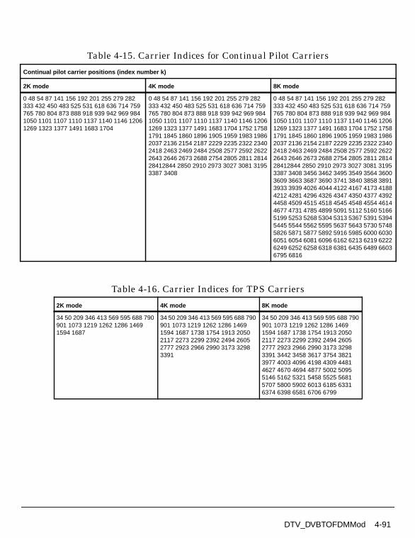
Table 4-15. Carrier Indices for Continual Pilot Carriers
Continual pilot carrier positions (index number k)
2K mode 4K mode 8K mode
0 48 54 87 141 156 192 201 255 279 282333 432 450 483 525 531 618 636 714 759765 780 804 873 888 918 939 942 969 9841050 1101 1107 1110 1137 1140 1146 12061269 1323 1377 1491 1683 1704
0 48 54 87 141 156 192 201 255 279 282333 432 450 483 525 531 618 636 714 759765 780 804 873 888 918 939 942 969 9841050 1101 1107 1110 1137 1140 1146 12061269 1323 1377 1491 1683 1704 1752 17581791 1845 1860 1896 1905 1959 1983 19862037 2136 2154 2187 2229 2235 2322 23402418 2463 2469 2484 2508 2577 2592 26222643 2646 2673 2688 2754 2805 2811 281428412844 2850 2910 2973 3027 3081 31953387 3408
0 48 54 87 141 156 192 201 255 279 282333 432 450 483 525 531 618 636 714 759765 780 804 873 888 918 939 942 969 9841050 1101 1107 1110 1137 1140 1146 12061269 1323 1377 1491 1683 1704 1752 17581791 1845 1860 1896 1905 1959 1983 19862037 2136 2154 2187 2229 2235 2322 23402418 2463 2469 2484 2508 2577 2592 26222643 2646 2673 2688 2754 2805 2811 281428412844 2850 2910 2973 3027 3081 31953387 3408 3456 3462 3495 3549 3564 36003609 3663 3687 3690 3741 3840 3858 38913933 3939 4026 4044 4122 4167 4173 41884212 4281 4296 4326 4347 4350 4377 43924458 4509 4515 4518 4545 4548 4554 46144677 4731 4785 4899 5091 5112 5160 51665199 5253 5268 5304 5313 5367 5391 53945445 5544 5562 5595 5637 5643 5730 57485826 5871 5877 5892 5916 5985 6000 60306051 6054 6081 6096 6162 6213 6219 62226249 6252 6258 6318 6381 6435 6489 66036795 6816
Table 4-16. Carrier Indices for TPS Carriers
2K mode 4K mode 8K mode
34 50 209 346 413 569 595 688 790901 1073 1219 1262 1286 14691594 1687
34 50 209 346 413 569 595 688 790901 1073 1219 1262 1286 14691594 1687 1738 1754 1913 20502117 2273 2299 2392 2494 26052777 2923 2966 2990 3173 32983391
34 50 209 346 413 569 595 688 790901 1073 1219 1262 1286 14691594 1687 1738 1754 1913 20502117 2273 2299 2392 2494 26052777 2923 2966 2990 3173 32983391 3442 3458 3617 3754 38213977 4003 4096 4198 4309 44814627 4670 4694 4877 5002 50955146 5162 5321 5458 5525 56815707 5800 5902 6013 6185 63316374 6398 6581 6706 6799
DTV_DVBTOFDMMod 4-91
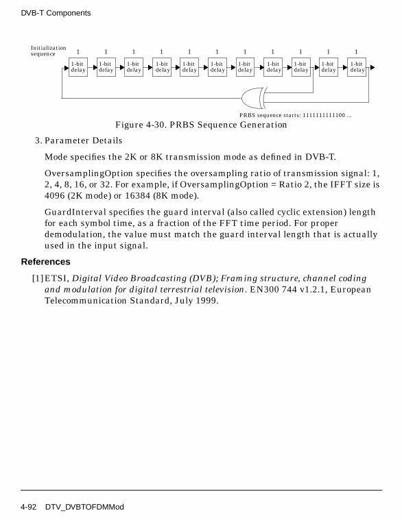
DVB-T Components
Figure 4-30. PRBS Sequence Generation
3. Parameter Details
Mode specifies the 2K or 8K transmission mode as defined in DVB-T.
OversamplingOption specifies the oversampling ratio of transmission signal: 1,2, 4, 8, 16, or 32. For example, if OversamplingOption = Ratio 2, the IFFT size is4096 (2K mode) or 16384 (8K mode).
GuardInterval specifies the guard interval (also called cyclic extension) lengthfor each symbol time, as a fraction of the FFT time period. For properdemodulation, the value must match the guard interval length that is actuallyused in the input signal.
References
[1]ETSI, Digital Video Broadcasting (DVB); Framing structure, channel codingand modulation for digital terrestrial television. EN300 744 v1.2.1, EuropeanTelecommunication Standard, July 1999.
1
1-bitdelay
1
1-bitdelay
1
1-bitdelay
1
1-bitdelay
1
1-bitdelay
1
1-bitdelay
1
1-bitdelay
1
1-bitdelay
1
1-bitdelay
1
1-bitdelay
1
1-bitdelay
Initializationsequence
PRBS sequence starts: 1111111111100 ...
4-92 DTV_DVBTOFDMMod

DTV_DVBTPS
Description Transmission parameter signal information bitsLibrary DTV, DVB-TClass SDFDTV_DVBTPS
Parameters
Name Description Default Type Range
Length length of TPS informationbits
54 int 54
InitiBit initialization bit for DBPSKmodulation (1 bit)
1 int 0, 1
Sync synchronization word (16bits): W0, W1
W0 enum
LengthIndicator TPS length indicator (6bits)
0 1 0 1 1 1 int array "0 1 0 1 1 1"
FrameNumber frame number in one superframe (2 bits): F1, F2, F3,F4
F1 enum
Constellation modulation scheme inDVB-T (2bits): QPSK,QAM 16, QAM 64,reserved M
QPSK enum
HierarchyInform signaling format for alphavalues (3 bits): Nonhierarchical, alpha 1, alpha2, alpha 4, reserved H1,reserved H2, reserved H3,reserved H4
Non hierarchical enum
CodeRateHP high priority stream currentcode rate (3 bits): HP 1/2,HP 2/3, HP 3/4, HP 5/6,HP 7/8, Reserved C1 HP,Reserved C2 HP,Reserved C3 HP
HP 1/2 enum
DTV_DVBTPS 4-93

DVB-T Components
Pin Outputs
Notes/Equations
1. This model generates 54 bits of TPS information; refer to Table 4-17 for bitassignments.
CodeRateLP low priority stream currentcode rate (3 bits): LP 1/2,LP 2/3, LP 3/4, LP 5/6, LP7/8, Reserved C1 LP,Reserved C2 LP, ReservedC3 LP
LP 1/2 enum
GuardInterval guard interval values (2bits): G 1/32, G 1/16, G1/8, G 1/4
G 1/32 enum
TransmissionMode transmission mode (2 bits):mode 2k, mode 8k,reserved T1, reserved T2
mode 2k enum
FutureUse reserved for future use(currently, all 14 bits are setto 0)
0 0 0 0 0 0 0 0 0 00 0 0 0
int array
Pin Name Description Signal Type
1 output TPS information bits int
2 initial initial bit for differential modulation int
Table 4-17. PS Signal Information and Format
Bit No. Format Purpose/Content
S0 Initialization bit for differential 2_PSK modulation
S1 − S160011010111101110 or1100101000010001
Synchronization word
S17 − S22010 111 Length indicator
S23 − S24 See Table 4-18 Frame number
S25 − S26 See Table 4-19 Constellation
S27 − S29 See Table 4-20 Hierarchy information
S30 − S32 See Table 4-21 Code rate, HP stream
S33 − S35 See Table 4-21 Code rate, LP stream
Name Description Default Type Range
4-94 DTV_DVBTPS

S36 − S37 See Table 4-22 Guard interval
S38 − S39 See Table 4-23 Transmission mode
S40 − S52all set to 0 Reserved for future use
S54 − S66BCH code Error protection
Table 4-18. Signal Format for Frame Number
Bits S23 - S24 Frame Number
00 Frame number 1 in the super-frame
01 Frame number 2 in the super-frame
10 Frame number 3 in the super-frame
11 Frame number 4 in the super-frame
Table 4-19. Signal Format for Possible Constellation Patterns
Bits S25 - S26 Constellation Characteristics
00 QPSK
01 16-QAM
10 64-QAM
11 reserved
Table 4-20. Signal Format for α Values
Bits S27 - S29 α Value
000 Non-hierarchical
001 α = 1
010 α = 2
011 α = 3
100 reserved
101 reserved
110 reserved
111 reserved
Table 4-17. PS Signal Information and Format (continued)
Bit No. Format Purpose/Content
DTV_DVBTPS 4-95

DVB-T Components
References
[1]ETSI, Digital Video Broadcasting (DVB); Framing structure, channel codingand modulation for digital terrestrial television. EN300 744 v1.2.1, EuropeanTelecommunication Standard, July 1999.
Table 4-21. Signal Format for Each Code Rate
BitsS30 - S32 HP stream
S33 - S35 LP stream Code Rate
000 1/2
001 2/3
010 3/4
011 5/6
100 7/8
101 reserved
110 reserved
111 reserved
Table 4-22. Signal Format for Each Guard Interval
Bits S36 - S37 Guard Interval Values
00 1/32
01 1/16
10 1/8
11 1/4
Table 4-23. Signal Format for Transmission Mode
Bits S38 - S39 Transmission Mode
00 2K mode
01 8K mode
10 reserved
11 reserved
4-96 DTV_DVBTPS
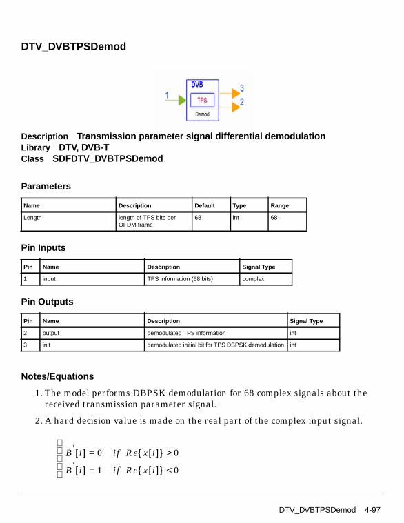
DTV_DVBTPSDemod
Description Transmission parameter signal differential demodulationLibrary DTV, DVB-TClass SDFDTV_DVBTPSDemod
Parameters
Pin Inputs
Pin Outputs
Notes/Equations
1. The model performs DBPSK demodulation for 68 complex signals about thereceived transmission parameter signal.
2. A hard decision value is made on the real part of the complex input signal.
Name Description Default Type Range
Length length of TPS bits perOFDM frame
68 int 68
Pin Name Description Signal Type
1 input TPS information (68 bits) complex
Pin Name Description Signal Type
2 output demodulated TPS information int
3 init demodulated initial bit for TPS DBPSK demodulation int
B′ i[ ] 0= if Re x i[ ] 0>
B′ i[ ] 1= if Re x i[ ] 0<
DTV_DVBTPSDemod 4-97

DVB-T Components
where
0 ≤ i < 68.
Then set B0 = B′ [0]. DBPSK demodulation is:
Bi = B′ [i] ⊕ B′ [i − 1]
where
i=1, 2, ... , 67.
References
[1]ETSI, Digital Video Broadcasting (DVB); Framing structure, channel codingand modulation for digital terrestrial television. EN300 744 v1.2.1, EuropeanTelecommunication Standard, July 1999.
4-98 DTV_DVBTPSDemod

DTV_DVBTPSMod
Description Transmission parameter signal differential modulationLibrary DTV, DVB-TClass SDFDTV_DVBTPSMod
Parameters
Pin Inputs
Pin Outputs
Notes/Equations
1. The model performs DBPSK modulation for transmission parameter signalinformation.
Name Description Default Type Range
Length length of TPS bits perOFDM frame
68 int 68
Pin Name Description Signal Type
1 input TPS information (67 bits) int
2 initial initial bit for TPS DBPSK modulation int
Pin Name Description Signal Type
3 output modulated TPS information complex
DTV_DVBTPSMod 4-99

DVB-T Components
2. Implementation
First, set, B′ [0] = B0. DBPSK modulation is
B′ [i] = Bi ⊕ B′ [i − 1]
where i=1, 2, ... , 67.
Then
,
coded bits B′ [0] ~ B′ [67] are converted to (1,0), (-1, 0)
where
i=0,1, ... , 67.
References
[1]ETSI, Digital Video Broadcasting (DVB); Framing structure, channel codingand modulation for digital terrestrial television. EN300 744 v1.2.1, EuropeanTelecommunication Standard, July 1999.
x i[ ] 1 j0+= if B′ i[ ] 0=( )
x i[ ] 1– j0+= if B′ i[ ] 1=( )
4-100 DTV_DVBTPSMod

DTV_DVBTReceiver
Description DVB-T receiverLibrary DTV, DVB-T
Parameters
Pin Inputs
Pin Outputs
Name Description Default Sym Type Range
Mode transmission mode: DVB2k mode, DVB 8k mode
DVB 2k mode enum
OversamplingOption oversampling ratio option:Ratio 1, Ratio 2, Ratio 4,Ratio 8, Ratio 16, Ratio 32
Ratio 1 S enum
GuardInterval guard interval (frac FFTsize)
0.125 real [0, 1]
CodeRate code rate: DTV 1/2, DTV2/3, DTV 3/4, DTV 5/6,DTV 7/8
DTV 1/2 enum
MappingMode signal constellations andmapping: QPSK, QAM-16,QAM-64
QAM-16 enum
SoftDecision soft decision viterbidecoding type: Soft, Hard,Cochannel
Soft enum
TrunLen path memory truncationlength of Viterbi decodingalgorithm, in bytes
10 int [5, ∞)
Pin Name Description Signal Type
1 Rx_signal received OFDM signal to be demodulated complex
Pin Name Description Signal Type
2 Bytes_Decoded decoded bytes after Reed Solomon decoder int
3 Bytes_AfterViterbi decoded bytes after Viterbi decoder int
DTV_DVBTReceiver 4-101

DVB-T Components
Notes/Equations
1. This subnetwork model implements the DVB-T receiver function. Theschematic for this subnetwork is shown in Figure 4-31.
Figure 4-31. DTV_DVBTReceiver Schematic
2. Output Delays
The constellation pin has one OFDM symbol delay. The first 8 × 1705 (2K mode)or 8 × 6817 (8K mode) constellation output signals not used for EVMcalculation.
DTV_BCHDecoder works a 68-bit block; so, a Delay component with N=60 isinserted before DTV_DVBTPSDemod. TPS_Bits has a one DVB-T frame (68OFDM symbols) delay; the first 53 bits are not used.
The information bytes per one OFDM symbol in Bytes_AfterViterbi can becalculated as follows:
• DataPerOFDMSymbol=1512 (2K mode) or 6048 (8K mode)
• CodedBlockSize=204
4 TPS_Bits decoded TPS information bits int
5 constellation constellation signal after OFDM demodulation complex
Pin Name Description Signal Type
4-102 DTV_DVBTReceiver

• CodeRate = 1/2, 2/3, 3/4, 5/6 or 7/8,
• InfoBytes=DelayOFDMSymbols×DataPerOFDMSymbol×CodeRate/8
• DelayOFDMSymbols = 8
The block delay of Bytes_AfterViterbi is BlockDelay_AfterViterbi and can becalculated, as follows:
• DelayBytes=DelayOFDMSymbols×InfoBytes-(int(DelayOFDMSymbols×InfoBytes/CodedBlockSize))×CodedBlockSize,
• N=int((TrunLen+DelayBytes)/CodedBlockSize),
• BlockDelay_AfterViterbi=1+int((DelayOFDMSymbols×InfoBytes)/CodedBlockSize)+N.
The block size is 204 bytes, N is used when the sum of TrunLen andDelayBytes is more than one block length.
The Bytes_Decoded pin has 11 extra transport MUX packet delays.
The block delay of Bytes_Decoded is
BlockDelay_Decoded=1+int((DelayOFDMSymbols×InfoBytes)/CodedBlockSize)+N.
The block size is 188 bytes.
3. Receiver functions are implemented according to the DVB-T Standard.
Start of OFDM symbol is detected by the DTV_DVBTOFDMDemod subnetwork(shown in Figure 4-32).
DTV_DVBTReceiver 4-103

DVB-T Components
Figure 4-32. DTV_DVBTOFDMDemod Schematic
DTV_MLEstimator calculates the correlation based on guard interval;DTV_LoadFFTBuff selects the index with the maximum correlation value asthe start of FFT.
DTV_DVBCh2DEstimator estimates the complex channel impulse responsesfor continual and scattered pilot subcarriers. The channel impulse responses ofthe data subcarriers are 2D interpolated based on the estimated CIR.
Each subcarrier value is divided with a complex estimated channel responsecoefficient (phase tracking, phase synchronization, and equalization). Thissimple one-tap frequency domain channel response compensation isimplemented by DTV_OFDMEqualizer.
After equalization, DTV_DVBDemuxOFDMSym demultiplexes 1705 or 6817subcarriers into 1512 (2K mode) or 6048 (8K mode) data subcarriers and 1demodulated TPS.
The demodulated 1512 or 6048 data subcarriers (such as 16-QAM and 64-QAMmodulation) are demapped by DTV_Demapper.
4-104 DTV_DVBTReceiver

Demodulated soft bits are de-interleaved by DTV_DVBTInnerDeinterlv.
De-interleaved bits are then inner decoded (DTV_InnerDecoder), outerde-interleaved (DTV_InterlvInt), outer decoded (DTV_RSDecoder) anddescrambled (DTV_ScrambleByte).
The fully decoded stream bytes are then output as Bytes_Decoded.
The partially decoded stream bytes after inner decoding are output asBytes_AfterViterbi.
The TPS signal is demodulated by DTV_DVBTPSDemod; the demodulated bitsare decoded by DTV_BCHDecoder.
The output pins of this DTV_DVBTReceiver subnetwork correspond to those ofDTV_DVBTSignalSrc.
This receiver is triggered per one OFDM symbol. The number of samples ofeach OFDM symbol (Rx_signal input pin) is:
• (1+GuardInterval)×2048×OversamplingRatio (2K mode)
• (1+GuardInterval)×8192×OversamplingRatio (8K mode)
The number of signals at the constellation output pin is 1705 (2K mode) or 6817(8K mode) per one OFDM symbol.
4. Parameter Details
Mode specifies the 2K or 8K transmission mode as defined in DVB-T.
OversamplingOption specifies the transmission signal oversampling ratio 1, 2,4, 8, 16, 32. If OversamplingOption = Ratio 2, the IFFT size is 4096 (2K mode)or 16384 (8K mode).
GuardInterval specifies the guard interval (also called cyclic extension) lengthfor each symbol time, as a fraction of the FFT time period. Guard interval types1/4, 1/8, 1/16 and 1/32 are defined in the DVB-T specification. GuardIntervalcan be set to any value between 0.0 and 1.0 (not just 1/4, 1/8, 1/16 and 1/32). Forproper demodulation, the value must match the guard interval length actuallyused in the input signal.
CodeRate specifies the DTV code rate: 1/2, 2/3, 3/4, 5/6 or 7/8.
MappingMode specifies signal constellation and mapping modes: QPSK,QAM-16, or QAM-64.
SoftDecision specifies the Viterbi decoding algorithm mode.
DTV_DVBTReceiver 4-105

DVB-T Components
• If SoftDecision=Soft, the Viterbi decoding algorithm is a soft decision decoderand uses channel status information.
• If SoftDecision=Hard, the Viterbi decoding algorithm is a hard decisiondecoder and does not use channel status information.
• If SoftDecision=Cochannel, the Viterbi decoding algorithm is for co-channelmeasurement with PAL analog TV and digital DVB-T.
TrunLen sets the truncation length (in bytes) in the Viterbi decoding algorithm.The path memory is 8×TrunLen bits in Viterbi decoding algorithm.
References
[1]ETSI, Digital Video Broadcasting (DVB); Framing structure, channel codingand modulation for digital terrestrial television. EN300 744 v1.2.1, EuropeanTelecommunication Standard, July 1999.
[2] W.C.Lee, H.M.Park, K.J.Kang, K.B.Kim, “Performance Analysis of ViterbiDecoder Using Channel State Information in COFDM System” IEEETRANSACTIONS ON BROADCASTING, Vol.,44, NO.4, DECEMBER 1998.
4-106 DTV_DVBTReceiver
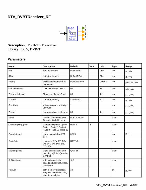
DTV_DVBTReceiver_RF
Description DVB-T RF receiverLibrary DTV, DVB-T
Parameters
Name Description Default Sym Unit Type Range
RIn input resistance DefaultRIn Ohm real (0, ∞)
ROut output resistance DefaultROut Ohm real (0, ∞)
RTemp physical temperature, indegrees C
DefaultRTemp Celsius real [-273.15, ∞)
GainImbalance Gain imbalance, Q vs I 0.0 dB real (-∞, ∞)
PhaseImbalance Phase imbalance, Q vs I 0.0 deg real (-∞, ∞)
FCarrier carrier frequency 474.0MHz Hz real (0, ∞)
Sensitivity voltage output sensitivity,Vout/Vin
1 real (-∞, ∞)
Phase reference phase in degrees 0.0 deg real (-∞, ∞)
Mode transmission mode: DVB2k mode, DVB 8k mode
DVB 2k mode enum
OversamplingOption oversampling ratio option:Ratio 1, Ratio 2, Ratio 4,Ratio 8, Ratio 16, Ratio 32
Ratio 1 S enum
GuardInterval guard interval (frac FFTsize)
0.125 real [0, 1]
CodeRate code rate: DTV 1/2, DTV2/3, DTV 3/4, DTV 5/6,DTV 7/8
DTV 1/2 enum
MappingMode signal consetllaions andmapping: QPSK, QAM-16,QAM-64
QAM-16 enum
SoftDecision soft decision viterbidecoding type: Soft, Hard,Cochannel
Soft enum
TrunLen path memory truncationlength of Viterbi decodingalgorithm, in bytes
10 int [5, ∞)
DTV_DVBTReceiver_RF 4-107

DVB-T Components
Pin Inputs
Pin Outputs
Notes/Equations
1. This subnetwork model implements the DVB-T RF receiver function. Thereceived RF signal is demodulated and fed to the baseband receiver.
2. The schematic for this RF receiver is shown in Figure 4-33.
Figure 4-33. DTV_DVBTReceiver_RF Schematic
3. The baseband demodulator schematic is shown in Figure 4-34.
Pin Name Description Signal Type
1 Rx_signal received OFDM signal to be demodulated timed
Pin Name Description Signal Type
2 Bytes_Decoded decoded bytes after Reed Solomon decoder int
3 Bytes_AfterViterbi decoded bytes after Viterbi decoder int
4 TPS_Bits decoded TPS information bits int
5 constellation constellation signal after OFDM demodulation complex
4-108 DTV_DVBTReceiver_RF

Figure 4-34. DTV_DVBTReceiver Schematic
4. Output Delays
The constellation pin has one OFDM symbol delay. The first 8 × 1705 (2K mode)or 8 × 6817 (8K mode) constellation output signals not used for EVMcalculation.
DTV_BCHDecoder works a 68-bit block; so, a Delay component with N=60 isinserted before DTV_DVBTPSDemod. TPS_Bits has a one DVB-T frame (68OFDM symbols) delay; the first 53 bits are not used.
The information bytes for one OFDM symbol in Bytes_AfterViterbi can becalculated as follows:
• DataPerOFDMSymbol=1512 (2K mode) or 6048 (8K mode)
• CodedBlockSize=204
• CodeRate = 1/2, 2/3, 3/4, 5/6 or 7/8,
• InfoBytes=DelayOFDMSymbols×DataPerOFDMSymbol×CodeRate/8
• DelayOFDMSymbols = 8
The block delay of Bytes_AfterViterbi is BlockDelay_AfterViterbi and can becalculated, as follows:
DTV_DVBTReceiver_RF 4-109

DVB-T Components
• DelayBytes=DelayOFDMSymbols×InfoBytes-(int(DelayOFDMSymbols×InfoBytes/CodedBlockSize))×CodedBlockSize,
• N=int((TrunLen+DelayBytes)/CodedBlockSize),
• BlockDelay_AfterViterbi=1+int((DelayOFDMSymbols×InfoBytes)/CodedBlockSize)+N.
The block size is 204 bytes, N is used when the sum of TrunLen andDelayBytes is more than one block length.
The block size is 204 bytes, N is used when the sum of TrunLen andDelayBytes is more than one block length.
The Bytes_Decoded pin has 11 extra transport MUX packet delays.
The block delay of Bytes_Decoded is
BlockDelay_Decoded=1+int((DelayOFDMSymbols×InfoBytes)/CodedBlockSize)+N.
The block size is 188 bytes.
5. Receiver functions are implemented according to the DVB-T Standard.
Start of OFDM symbol is detected by the DTV_DVBTOFDMDemod subnetwork(shown in Figure 4-35).
4-110 DTV_DVBTReceiver_RF

Figure 4-35. DTV_DVBTOFDMDemod Schematic
DTV_MLEstimator calculates the correlation based on guard interval;DTV_LoadFFTBuff selects the index with the maximum correlation value asthe start of FFT.
DTV_DVBCh2DEstimator estimates the complex channel impulse responsesfor continual and scattered pilot subcarriers. The channel impulse responses ofthe data subcarriers are 2D interpolated based on the estimated CIR.
Each subcarrier value is divided with a complex estimated channel responsecoefficient (phase tracking, phase synchronization, and equalization). Thissimple one-tap frequency domain channel response compensation isimplemented by DTV_OFDMEqualizer.
After equalization, DTV_DVBDemuxOFDMSym demultiplexes 1705 or 6817subcarriers into 1512 (2K mode) or 6048 (8K mode) data subcarriers and 1demodulated TPS.
The demodulated 1512 or 6048 data subcarriers (16-QAM and 64-QAMmodulation) are demapped by DTV_Demapper.
DTV_DVBTReceiver_RF 4-111

DVB-T Components
Demodulated soft bits are de-interleaved by DTV_DVBTInnerDeinterlv.
De-interleaved bits are then inner decoded (DTV_InnerDecoder), outerde-interleaved (DTV_InterlvInt), outer decoded (DTV_RSDecoder) anddescrambled (DTV_ScrambleByte).
The fully decoded stream bytes are then output as Bytes_Decoded.
The partially decoded stream bytes after inner decoding are output asBytes_AfterViterbi.
The TPS signal is demodulated by DTV_DVBTPSDemod; the demodulated bitsare decoded by DTV_BCHDecoder.
The output pins of this DTV_DVBTReceiver subnetwork correspond to those ofDTV_DVBTSignalSrc.
This receiver is triggered at each OFDM symbol. The number of samples of eachOFDM symbol (Rx_signal input pin) is:
• (1+GuardInterval)×2048×OversamplingRatio (2K mode)
• (1+GuardInterval)×8192×OversamplingRatio (8K mode)
The number of signals at the constellation output pin is 1705 (2K mode) or 6817(8K mode) for one OFDM symbol.
6. Parameter Details
GainImbalance and PhaseImbalance add certain impairments to the idealoutput RF signal. Impairments are added in the order described here.
The unimpaired RF I and Q envelope voltages have gain and phase imbalanceapplied. The RF is given by:
where V1(t) is the in-phase RF envelope, V2(t) is the quadrature phase RFenvelope, g is the gain imbalance
and, φ (in degrees) is the phase imbalance.
Mode specifies the 2K or 8K transmission mode as defined in DVB-T.
V3 t( ) A V1 t( ) ωct( )cos gV2 t( ) ωctφπ180---------+
sin– =
g 10
GainImbalance20
-----------------------------------------------
=
4-112 DTV_DVBTReceiver_RF

OversamplingOption specifies the transmission signal oversampling ratio 1, 2,4, 8, 16, 32. If OversamplingOption=Ratio 2, the IFFT size is 4096 for 2K modeor 16384 for 8K mode.
GuardInterval specifies the guard interval (also called cyclic extension) lengthfor each symbol time, as a fraction of the FFT time period. Guard interval types1/4, 1/8, 1/16 and 1/32 are defined in the DVB-T specification. GuardIntervalcan be set to any value between 0.0 and 1.0 (not just 1/4, 1/8, 1/16 and 1/32). Forproper demodulation, the value must match the guard interval length actuallyused in the input signal.
CodeRate specifies the stream code rate: 1/2, 2/3, 3/4, 5/6, or 7/8.
MappingMode specifies signal constellations and mapping for the DVB-T signalsource. Mapping modes QPSK, 16-QAM and 64-QAM are available.
SoftDecision specifies the Viterbi decoding algorithm mode.
• If SoftDecision=Soft, the Viterbi decoding algorithm is a soft decision decoderand uses channel status information.
• If SoftDecision=Hard, the Viterbi decoding algorithm is a hard decisiondecoder and does not use channel status information.
• If SoftDecision=Cochannel, the Viterbi decoding algorithm is for co-channelmeasurement with PAL analog TV and digital DVB-T.
TrunLen is set to the truncation length in the Viterbi decoding algorithm. Thisparameter is set as bytes. The path memory is 8×TrunLen bits in Viterbidecoding algorithm.
TrunLen sets the truncation length (in bytes) in the Viterbi decoding algorithm.The path memory is 8×TrunLen bits in Viterbi decoding algorithm.
References
[1]ETSI, Digital Video Broadcasting (DVB); Framing structure, channel codingand modulation for digital terrestrial television. EN300 744 v1.2.1, EuropeanTelecommunication Standard, July 1999
[2] W.C.Lee, H.M.Park, K.J.Kang, K.B.Kim, “Performance Analysis of ViterbiDecoder Using Channel State Information in COFDM System” IEEETRANSACTIONS ON BROADCASTING, Vol.,44,NO.4, DECEMBER 1998.
DTV_DVBTReceiver_RF 4-113

DVB-T Components
DTV_DVBTSignalSrc
Description DVB-T signal sourceLibrary DTV, DVB-T
Parameters
Pin Outputs
Notes/Equations
Name Description Default Sym Type Range
Mode transmission mode: DVB2k mode, DVB 8k mode
DVB 2k mode enum
OversamplingOption oversampling ratio option:Ratio 1, Ratio 2, Ratio 4,Ratio 8, Ratio 16, Ratio 32
Ratio 1 S enum
GuardInterval guard interval (fractionalFFT size)
0.125 real [0, 1]
CodeRate code rate: DTV 1/2, DTV2/3, DTV 3/4, DTV 5/6,DTV 7/8
DTV 1/2 enum
MappingMode signal constellation andmapping: QPSK, QAM-16,QAM-64
QAM-16 enum
DataType payload data type: PN9,PN15, FIX4, _4_1_4_0,_8_1_8_0, _16_1_16_0,_32_1_32_0, _64_1_64_0
PN9 enum
Pin Name Description Signal Type
1 DVBT_signal DVB-T signal complex
2 Bytes_Uncoded information bytes of transport packet int
3 Bytes_BeforeCC information bytes before convolutional coder int
4 TPS_Bits TPS information bits int
5 constellation constellation signal before IFFT complex
4-114 DTV_DVBTSignalSrc

1. This subnetwork model generates a DVB-T signal source. One OFDM symbol isgenerated each firing.
The schematic for this subnetwork is shown in Figure 4-36.
Figure 4-36. DTV_DVBTSignalSrc Schematic
2. The DVB-T signal source format follows the DVB-T specification. Figure 4-37 isfunctional block diagram of the DVB-T baseband system.
The DTV_DVBTSignalSrc includes: scrambler (DTV_ScrambleByte); outercoder (DTV_RSCoder); outer interleaver (DTV_InterlvInt); inner coder(DTV_PuncConvCoder); inner interleaver (DTV_DVBTInnerInterlv); mapper(DTV_Mapper); and, frame adaptation, OFDM, and guard interval insertion (inDTV_DVBTOFDMMod subnetwork).
DTV_DVBTSignalSrc 4-115

DVB-T Components
Figure 4-37. DVB-T Baseband System Block Diagram
For a MPEG-2 transport stream, the DTV_DVBTTSPsource model can beactivated (shown de-activated in Figure 4-36) and the current active sourcedeactivated. DTV_DVBTSignalSrc requires more buffer than the current activesource; for example, a code rate of 7/8 is too large.
This signal source works per one OFDM symbol. The number of constellationoutput pin is 1705 (2K mode) or 6817 (8K mode) per one OFDM symbol. Thenumber of samples of each OFDM symbol (DVBT_signal output pin) is:
• (1+GuardInterval)×2048×OversamplingRatio (2K mode)
• (1+GuardInterval)×8192×OversamplingRatio (8K mode)
3. Parameter Details
Mode is used to select a 2K or 8K transmission mode as defined in DVB-T.
OversamplingOption indicates the oversampling ratio of the transmissionsignal. Oversampling ratios 1, 2, 4, 8, 16, 32 are supported in this source. IfOversamplingOption = Ratio 2, the IFFT size is 4096 (2K mode) or 16384 (8Kmode).
GuardInterval specifies the guard interval (also called cyclic extension) lengthfor each symbol time, as a fraction of the FFT time period. Guard interval types1/4, 1/8, 1/16 and 1/32 are defined in the DVB-T specification. GuardIntervalcan be set to any value between 0.0 and 1.0 (not just 1/4, 1/8, 1/16 and 1/32). Forproper demodulation, the value must match the guard interval length actuallyused in the input signal.
CodeRate is defined as code rate of stream. Code rates1/2, 2/3, 3/4, 5/6 and 7/8are available in this source.
MappingMode specifies signal constellations and mapping: QPSK, 16-QAM or64-QAM.
For the DataType parameter:
MUXAdaptation
EnergyDispersal
OuterCoder
OuterInterleaver
InnerCoder
InnerInterleaver Mapper
FrameAdaptation OFDM
GuardInterval
Insertion
MUXAdaptation
EnergyDispersal
OuterCoder
OuterInterleaver
InnerCoder
Pilot andTPS
Signals
4-116 DTV_DVBTSignalSrc

• if PN9 is selected, a 511-bit pseudo-random test pattern is generatedaccording to CCITT Recommendation O.153
• if PN15 is selected, a 32767-bit pseudo-random test pattern is generatedaccording to CCITT Recommendation O.151
• if FIX4 is selected, a zero-stream is generated
• if x_1_x_0 is selected (x equals 4, 8, 16, 32, or 64) a periodic bit stream isgenerated, with the period being 2x. In one period, the first x bits are 1s andthe second x bits are 0s.
References
[1]ETSI, Digital Video Broadcasting (DVB); Framing structure, channel codingand modulation for digital terrestrial television. EN300 744 v1.2.1, EuropeanTelecommunication Standard, July 1999.
DTV_DVBTSignalSrc 4-117

DVB-T Components
DTV_DVBTSignalSrc_RF
Description DVB-T RF signal sourceLibrary DTV, DVB-T
Parameters
Name Description Default Sym Unit Type Range
ROut output resistance DefaultROut Ohm real (0, ∞)
RTemp physical temperature, indegrees C
DefaultRTemp Celsius real [-273.15, ∞)
Noise Enable thermal noise? NO,YES
NO enum
FCarrier carrier frequency 474.0MHz Hz real (0, ∞)
Power modulator output power 40mW W real (0, ∞)
Bandwidth bandwidth (2048/224.0)MHz Hz real (0, ∞)
MirrorSpectrum Mirror spectrum aboutcarrier? NO, YES
NO enum
GainImbalance Gain imbalance, Q vs I 0.0 dB real (-∞, ∞)
PhaseImbalance Phase imbalance, Q vs I 0.0 deg real (-∞, ∞)
I_OriginOffset I origin offset (percent) 0.0 real (-∞, ∞)
Q_OriginOffset Q origin offset (percent) 0.0 real (-∞, ∞)
IQ_Rotation IQ rotation 0.0 deg real (-∞, ∞)
Mode transmission mode: DVB2k mode, DVB 8k mode
DVB 2k mode enum
OversamplingOption oversampling ratio option:Ratio 1, Ratio 2, Ratio 4,Ratio 8, Ratio 16, Ratio 32
Ratio 1 S enum
GuardInterval guard interval (fractionalFFT size)
0.125 real [0, 1]
CodeRate code rate: DTV 1/2, DTV2/3, DTV 3/4, DTV 5/6,DTV 7/8
DTV 1/2 enum
4-118 DTV_DVBTSignalSrc_RF

Pin Outputs
Notes/Equations
1. This subnetwork model integrates an RF modulator and a baseband signalsource. The baseband signal is fed to the RF modulator; after RF modulationthe timed signal is output.
The schematic for this subnetwork is shown in Figure 4-38.
Figure 4-38. DTV_DVBTSignalSrc_RF Schematic
MappingMode signal constellation andmapping: QPSK, QAM-16,QAM-64
QAM-16 enum
DataType payload data type: PN9,PN15, FIX4, _4_1_4_0,_8_1_8_0, _16_1_16_0,_32_1_32_0, _64_1_64_0
PN9 enum
Pin Name Description Signal Type
1 RF_signal RF signal timed
2 DVBT_signal DVB-T signal complex
3 Bytes_Uncoded information bytes of transport packet int
4 Bytes_BeforeCC information bytes before convolutional coder int
5 TPS_Bits TPS information bits int
6 constellation constellation signal before IFFT complex
Name Description Default Sym Unit Type Range
DTV_DVBTSignalSrc_RF 4-119

DVB-T Components
2. The format of DVB-T signal source follows the DVB-T specification. Figure 4-39is a functional block diagram of a DVB-T baseband system.
Figure 4-39. DVB-T Baseband System Block Diagram
3. The schematic for the signal source is shown in Figure 4-40. TheDTV_DVBTSignalSrc includes: scrambler (DTV_ScrambleByte); outer coder(DTV_RSCoder); outer interleaver (DTV_InterlvInt); inner coder(DTV_PuncConvCoder); inner interleaver (DTV_DVBTInnerInterlv); mapper(DTV_Mapper); and, frame adaptation, OFDM, and guard interval insertion (inDTV_DVBTOFDMMod subnetwork).
Note To use an MPEG-2 transport stream, DTV_DVBTTSPsource must beactive and the current active source deactivated. DTV_DVBTTSPsource needsmore buffer than the current active source. In some cases, code rate 7/8 is toolarge.
MUXAdaptation
EnergyDispersal
OuterCoder
OuterInterleaver
InnerCoder
InnerInterleaver Mapper
FrameAdaptation OFDM
GuardInterval
Insertion
MUXAdaptation
EnergyDispersal
OuterCoder
OuterInterleaver
InnerCoder
Pilot andTPS
Signals
4-120 DTV_DVBTSignalSrc_RF

Figure 4-40. DTV_DVBTSignalSrc Schematic
This signal source uses one OFDM symbol; 1705 (2K mode) or 6817 (8K mode)constellations are output. DVBT_signal pin outputs samples for each OFDMsymbol:
• (1+GuardInterval)×2048×OversamplingRatio (2K mode)
• (1+GuardInterval)×8192×OversamplingRatio (8K mode)
4. Parameter Details
FCarrier defines the RF frequency for the DVB signal.
Power defines the power level for FCarrier.
Bandwidth indicates signal bandwidth.
The MirrorSpectrum (when set to YES) conjugates the input signal before anyother processing is done.
The GainImbalance, PhaseImbalance, I_OriginOffset, Q_OriginOffset, andIQ_Rotation parameters add certain impairments to the ideal output RF signal.Impairments are added in the order described here.
The unimpaired RF I and Q envelope voltages have gain and phase imbalanceapplied. The RF is given by:
DTV_DVBTSignalSrc_RF 4-121

DVB-T Components
where A is a scaling factor that depends on the Power and ROut parametersspecified by the user, V1(t) is the in-phase RF envelope, V2(t) is the quadraturephase RF envelope, g is the gain imbalance
and, φ (in degrees) is the phase imbalance.
The signal V3(t) is rotated by IQ_Rotation degrees; I_OriginOffset andQ_OriginOffset are then applied to the rotated signal. Note that the amountsspecified are percentages with respect to the output rms voltage. The outputrms voltage is given by sqrt(2×ROut×Power).
Mode specifies the 2K or 8K transmission mode as defined in the DVB-Tspecification.
OversamplingOption specifies the transmission signal oversampling ratio 1, 2,4, 8, 16, 32. If OversamplingOption=2, the IFFT size is 4096 (2K mode) or 16384(8K mode).
GuardInterval specifies the guard interval (also called cyclic extension) lengthfor each symbol time, as a fraction of the FFT time period. Guard interval types1/4, 1/8, 1/16 and 1/32 are defined in the DVB-T specification. GuardIntervalcan be set to any value between 0.0 and 1.0 (not just 1/4, 1/8, 1/16 and 1/32). Forproper demodulation, the value must match the guard interval length actuallyused in the input signal.
CodeRate specifies the stream code rate: 1/2, 2/3, 3/4, 5/6, or 7/8.
MappingMode specifies signal constellation and mapping modes: QPSK,16-QAM, or 64-QAM.
For the DataType parameter:
• if PN9 is selected, a 511-bit pseudo-random test pattern is generatedaccording to CCITT Recommendation O.153
• if PN15 is selected, a 32767-bit pseudo-random test pattern is generatedaccording to CCITT Recommendation O.151
• if FIX4 is selected, a zero-stream is generated
V3 t( ) A V1 t( ) ωct( )cos gV2 t( ) ωctφπ180---------+
sin– =
g 10
GainImbalance20
-----------------------------------------------
=
4-122 DTV_DVBTSignalSrc_RF

• if x_1_x_0 is selected, where x equals 4, 8, 16, 32, or 64, a periodic bit streamis generated, with the period being 2x. In one period, the first x bits are 1sand the second x bits are 0s.
References
[1]ETSI, Digital Video Broadcasting (DVB); Framing structure, channel codingand modulation for digital terrestrial television. EN300 744 v1.2.1, EuropeanTelecommunication Standard, July 1999.
DTV_DVBTSignalSrc_RF 4-123

DVB-T Components
DTV_DVBTTPSGen
Description Modulated transmission parameter signal informationLibrary DTV, DVB-TRequired Licenses
Parameters
Name Description Default Type Range
Length length of TPS informationbits
54 int 54
InitiBit initialization bit for DBPSKmodulation (1 bit)
1 int 0, 1
Sync synchronization word (16bits): W0, W1
W0 enum
LengthIndicator TPS length indicator (6bits)
0 1 0 1 1 1 int array "0 1 0 1 1 1"
FrameNumber frame number in one superframe (2 bits): F1, F2, F3,F4
F1 enum
Constellation modulation scheme inDVB-T (2bits): QPSK,QAM 16, QAM 64,reserved M
QPSK enum
HierarchyInform signaling format for alphavalues (3 bits): Nonhierarchical, alpha 1, alpha2, alpha 4, reserved H1,reserved H2, reserved H3,reserved H4
Non hierarchical enum
CodeRateHP high priority stream currentcode rate (3 bits): HP 1/2,HP 2/3, HP 3/4, HP 5/6,HP 7/8, Reserved C1 HP,Reserved C2 HP,Reserved C3 HP
HP 1/2 enum
CodeRateLP low priority stream currentcode rate (3 bits): LP 1/2,LP 2/3, LP 3/4, LP 5/6, LP7/8, Reserved C1 LP,Reserved C2 LP, ReservedC3 LP
LP 1/2 enum
4-124 DTV_DVBTTPSGen

Pin Outputs
Notes/Equations
1. This subnetwork model generates modulated transmission parameter signalinformation used in TPS carriers in OFDM symbols.
The schematic for this subnetwork is shown in Figure 4-41.
Figure 4-41. DTV_DVBTTPSGen Schematic
2. DTV_DVBTPS generates 54 bits (1 initialization, 16 synchronization, and 37information); the 53 TPS synchronization and information transmission modeare extended with 14 parity bits of the BCH (67,53, t = 2) shortened code,derived from the original systematic BCH (127,113, t = 2) code, which isimplemented by DTV_BCHCoder; the 68-bit TPS block is modulated byDBPSK, which is implemented by DTV_DVBTPSMod.
Each firing, the TPS_Bits pin outputs 53 bits (16 synchronization and 37information) and TPS outputs 68 modulated TPS signals.
3. The TPS is defined over 68 consecutive OFDM symbols (one OFDM frame).Four consecutive frames correspond to one OFDM super-frame.
GuardInterval guard interval values (2bits): G 1/32, G 1/16, G1/8, G 1/4
G 1/32 enum
TransmissionMode transmission mode (2 bits):mode 2k, mode 8k,reserved T1, reserved T2
mode 2k enum
FutureUse reserved for future use(currently, all 14 bits are setto 0)
0 0 0 0 0 0 0 0 0 00 0 0 0
int array
Pin Name Description Signal Type
1 TPS modulated TPS information signal complex
2 TPS_Bits TPS information bits int
Name Description Default Type Range
DTV_DVBTTPSGen 4-125

DVB-T Components
The reference sequence corresponding to the TPS carriers of the first symbol ofeach OFDM frame is used to initialize the TPS modulation on each TPS carrier.
Each OFDM symbol conveys one TPS bit. Each TPS block (corresponding to oneOFDM frame) contains 68 bits:
• 1 initialization bit
• 16 synchronization bits
• 37 information bits
• 14 redundancy bits for error protection
Of the 37 information bits, 31 are used (6 bits are reserved for future use andare set to zero).
4. Bit assignments are listed in Table 4-24.
Table 4-24. TPS Signal Information
Bit Number Format Purpose/Content
S0 Initialization bit for differential 2_PSK modulation
S1 − S160011010111101110 or1100101000010001
Synchronization word
S17 − S22010 111 Length indicator
S23 − S24 See Table 4-25 Frame number
S25 − S26 See Table 4-26 Constellation
S27 − S29 See Table 4-27 Hierarchy information
S30 − S32 See Table 4-28 Code rate, HP stream
S33 − S35 See Table 4-28 Code rate, LP stream
S36 − S37 See Table 4-29 Guard interval
S38 − S39 See Table 4-30 Transmission mode
S40 − S52all set to 0 Reserved for future use
S54 − S66BCH code Error protection
4-126 DTV_DVBTTPSGen

Table 4-25. Signal Format for Frame Number
Bits S23 − S24 Frame Number
00 1 in the super-frame
01 2 in the super-frame
10 3 in the super-frame
11 4 in the super-frame
Table 4-26. Signal Format for Constellation Patterns
Bits S25 − S26 Constellation Characteristics
00 QPSK
01 16-QAM
10 64-QAM
11 reserved
Table 4-27. Signal Format for α Values
Bits S27 − S29 α Value
000 Non-hierarchical
001 α = 1010 α = 3011 α = 3100 reserved
101 reserved
110 reserved
111 reserved
DTV_DVBTTPSGen 4-127

DVB-T Components
5. Error Protection of TPS
The 53 bits containing the TPS synchronization and information (bits s1 - s53)are extended with 14 parity bits of the BCH (67,53, t = 2) shortened code,derived from the original systematic BCH (127,113, t = 2) code.
The code generator polynomial is:
Table 4-28. Signal Format for Each Code Rate
Bits
S30 − S32 HP Stream
S33 − S35 LP Stream Code Rate
000 1/2
001 2/3
010 3/4
011 5/6
100 7/8
101 reserved
110 reserved
111 reserved
Table 4-29. Signal Format for Each Guard Interval
Bits S36 − S37 Guard Interval Values
00 1/32
01 1/16
10 1/8
11 1/4
Table 4-30. Signal Format for Transmission Mode
Bits S38 − S39 Transmission Mode
00 2K mode
01 8K mode
10 reserved
11 reserved
4-128 DTV_DVBTTPSGen
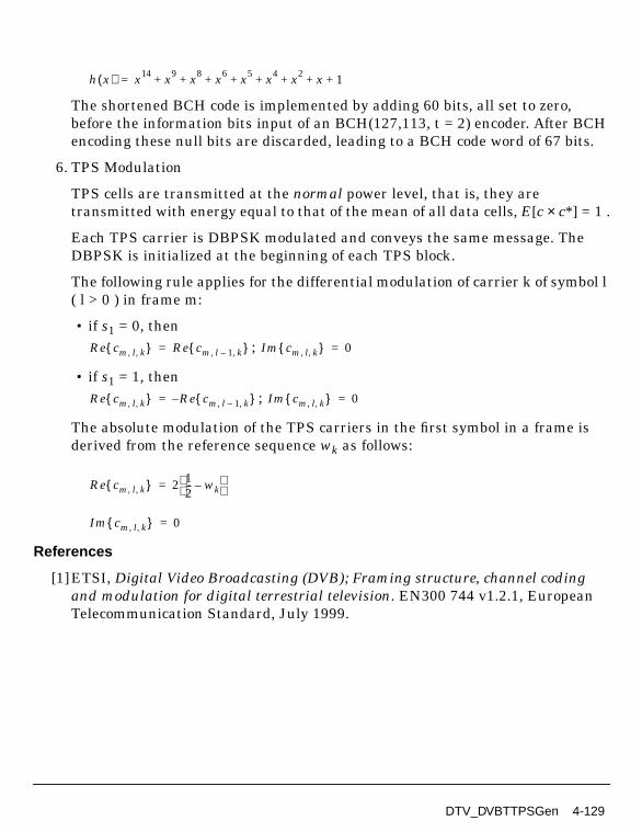
The shortened BCH code is implemented by adding 60 bits, all set to zero,before the information bits input of an BCH(127,113, t = 2) encoder. After BCHencoding these null bits are discarded, leading to a BCH code word of 67 bits.
6. TPS Modulation
TPS cells are transmitted at the normal power level, that is, they aretransmitted with energy equal to that of the mean of all data cells, E[c × c*] = 1 .
Each TPS carrier is DBPSK modulated and conveys the same message. TheDBPSK is initialized at the beginning of each TPS block.
The following rule applies for the differential modulation of carrier k of symbol l( l > 0 ) in frame m:
• if s1 = 0, then;
• if s1 = 1, then;
The absolute modulation of the TPS carriers in the first symbol in a frame isderived from the reference sequence wk as follows:
References
[1]ETSI, Digital Video Broadcasting (DVB); Framing structure, channel codingand modulation for digital terrestrial television. EN300 744 v1.2.1, EuropeanTelecommunication Standard, July 1999.
h x( ) x14 x9 x8 x6 x5 x4 x2 x 1+ + + + + + + +=
Re cm l k, , Re cm l 1– k, , = Im cm l k, , 0=
Re cm l k, , Re cm l 1– k, , –= Im cm l k, , 0=
Re cm l k, , 2 12--- wk–
=
Im cm l k, , 0=
DTV_DVBTTPSGen 4-129

DVB-T Components
DTV_DVBTTSPsource
Description Transport packets signal sourceLibrary DTV, DVB-TRequired Licenses
Parameters
Pin Outputs
Notes/Equations
1. This subnetwork model generates MEPG-2 transport MUX packets.
The schematic for this subnetwork is shown in Figure 4-42.
Name Description Default Type
DataType payload data type: PN9,PN15, FIX4, _4_1_4_0,_8_1_8_0, _16_1_16_0,_32_1_32_0, _64_1_64_0
PN9 enum
Pin Name Description Signal Type
1 TSP Transport system packet signal source int
4-130 DTV_DVBTTSPsource

Figure 4-42. DTV_DVBTTSPsource Schematic
2. Each firing, 8 transport packets with 8×188 bytes are generated as shown inFigure 4-43.
To provide an initialization signal for the descrambler, the MPEG-2 sync byte ofthe first transport packet in a group of 8 packets is bit-wise inverted from47HEX(71) to B8HEX(184). So, the first sync of the first packet is B8HEX(184) andthe left 7 sync of the left 7 packets are all 47HEX(71).
Figure 4-43. Transport Packet Format
3. DataPattern specifies the type of data pattern:
• PN9 specifies a 511-bit pseudo-random test pattern is generated according toCCITT Recommendation O.153
• PN15 specifies a 32767-bit pseudo-random test pattern is generatedaccording to CCITT Recommendation O.151
• FIX4 specifies a zero-stream is generated
SYNC1Randomized Data
187 bytesRandomized Data
187 bytesRandomized Data
187 bytesRandomized Data
187 bytesSYNC2 SYNC8 SYNC1
PRBS period = 1503 bytes
8 Transport MUX Packets
~ ~~ ~
~ ~~ ~
~ ~~ ~
DTV_DVBTTSPsource 4-131

DVB-T Components
• x_1_x_0 (where x equals 4, 8, 16, 32, or 64) specifies a periodic bit stream isgenerated, with the period being 2 x. In one period, the first x bits are 1 andthe second x bits are 0.
References
[1]ETSI, Digital Video Broadcasting (DVB); Framing structure, channel codingand modulation for digital terrestrial television. EN300 744 v1.2.1, EuropeanTelecommunication Standard, July 1999.
4-132 DTV_DVBTTSPsource

DTV_PALSource
Description PAL signal sourceLibrary DTV, DVB-TRequired Licenses
Parameters
Pin Outputs
Notes/Equations
1. The subnetwork model generates a PAL signal source. The PAL signal consistsof color bars, FM sound (+/- 50kHz dev, 1kHz tone), and NICAM.
The schematic for this subnetwork is shown in Figure 4-44.
Name Description Default Unit Type Range
RIn output resistance DefaultRIn Ohm real (0, ∞)
ROut output resistance DefaultROut Ohm real (0, ∞)
RTemp physical temperature, indegrees C
DefaultRTemp Celsius real [-273.15, ∞)
FCarrier carrier frequency 474.0MHz Hz real (0, ∞)
Power modulator output power 40mW W real (0, ∞)
VRef reference voltage foroutput power calibration
0.218V V real (0, ∞)
SamplingRate sampling rate (2048/224.0)MHz Hz real (0, ∞)
Pin Name Description Signal Type
1 PAL_signal PAL signal timed
DTV_PALSource 4-133

DVB-T Components
Figure 4-44. DTV_PALSource Schematic
2. This PAL signal source is implemented according to European Air UHF band IVchannel E21. E21 band limits are 470 to 478 MHz; center frequency is 474MHz; video carrier frequency is 471.25 MHz; audio carrier frequency is 477.25MHz; and, the NICAM carrier frequency is 477.802 MHz.
RF modulation occurs on the designated band.
FCarrier is the center frequency of the designated PAL channel. Power sets theRF modulator output power. SamplingRate is the PAL signal bandwidth; itsreciprocal is the RF modulation simulation time step.
References
[1]Recommendations of the CCIR, 1990, Volume XI - Part 1, Broadcasting Service(Television), CCIR (International Radio Consultative Committee), Geneva,1990.
[2] Recommendations of the CCIR, 1990, Annex to Volume XI - Part 1,Broadcasting Service (Television), CCIR (International Radio ConsultativeCommittee), Geneva, 1990.
[3] Recommendations of the CCIR, 1990, Volume XII, Television and SoundTransmission (CMTT), CCIR (International Radio Consultative Committee),Geneva, 1990.
[4] Reports of the CCIR, 1990, Annex to Volume XII, Television and SoundTransmission (CMTT), CCIR (International Radio Consultative Committee),Geneva, 1990.
4-134 DTV_PALSource

Chapter 5: ISDB-T Components
5-1

ISDB-T Components
DTV_CDSCDecoder
Description Complete differential set code (273,191) decoderLibrary DTV, ISDB-TClass SDFDTV_CDSCDecoder
Parameters
Pin Inputs
Pin Outputs
Notes/Equations
1. This model performs complete differential set code (273,191) error correctingdecoding over the input signal. After decoding, 184 or 273 bits are consumed atthe input and 102 or 191 bits are produced at the output.
2. For the shortened code, the same number of 0 symbols is inserted into the sameposition as the CDSC coder; a CDSC decoder is used to decode the block. Afterdecoding, the padded symbols are discarded, leaving the desired informationsymbols.
Generating Syndromes
Name Description Default Type Range
CodeLength length of code bits 184 int (0, 273]
Thresholds thresholds for errordetection
16 15 14 13 12 1110 9
int array [0, 17)
Pin Name Description Signal Type
1 input signal to be decoded int
Pin Name Description Signal Type
2 output decoded signal int
5-2 DTV_CDSCDecoder

In the general transmission of a codeword C from a cyclic code by a uniformq-ary input, q-ary output channel we seek the codeword that is nearest inHamming distance to the received sequence, R. Calculating the syndrome canbe done with a simple feedback shift register similar to the encoder circuit. Thisis an improvement over building (or programming) a general-purposemultiplication of the received sequence R with a parity check matrix H. Oncethe syndrome is calculated, it is possible to iteratively determine which codepositions are to be corrected by cycling the syndrome register.
We represent the actions of the channel by
where
represents the transmitted codeword and is the error sequence
with both from GF(q). In polynomial form, we express the channel action by
Now consider division of r(x) by g(x), generator polynomial for the code. This ismotivated by recalling the valid codewords are exactly divisible by g(x); that is,they produce zero remainder upon such division. We denote the remainder ofthis division as another polynomial, s(x), the syndrome polynomial:
Euclid’s division theorem implies that the syndrome polynomial is exactlydetermined by the error sequence, and s(x) will have degree n-k-1 or less.
To calculate the syndrome polynomial, we require a circuit for calculating theremainder on polynomial division. We provide a circuit and repeat the genericstructure of the syndrome calculation in Figure 5-1, a device having n-k q-aryregister cells. The circuit is clocked n times, at which time the syndrome vector(or polynomial) resides in the (n-k)- stage register, s0 is the left-most memorycell.
Once the syndrome vector is determined, the syndrome vector is used to detector correct errors.
R C E+=
C c0 c1 … cn 1–, , ,( )=
E e0 e1 … en 1–, , ,( )=
r x( ) c x( ) e x( )+=
s x( ) s0 s1x … sn k– xn k–+ + +=
r x( )modg x( ) c x( ) e x( )+[ ]modg x( )==
c x( )modg x( ) e x( )modg x( )+=
e x( )modg x( )=
DTV_CDSCDecoder 5-3

ISDB-T Components
Using Syndromes to Decode Cyclic Codes
Figure 5-1. Syndrome-Forming Circuit
CDSC (273,191) code is a one-order PG code. It can be decoded using a one-steplarge numeric logic method. This decoding method is simpler than the methodof decoding BCH codes. In this model, it only decodes the CDSC (273,191,d=18)and its shortened codes, such as (184,102).
Using the differential set of the CDSC (273,191), we can determine 17orthogonal check sums. The differential set of CDSC (273,191,d=18) is
0,18,24,46,50,67,103,112,115,126,128,159,166,167,186,196,201
The polynomial of the first orthogonal check sum is
The polynomial of the second orthogonal check sum is
The polynomial of the third orthogonal check sum is
. . .
The polynomial of the third orthogonal check sum is
g0 g1 g2 gn-k-1x x x x
+
x... -g-1n-k=-1
+ + +r0, r1, ... , rn-1
W1 x( ) x272 x254 x248 x226 x222 x205 x169 x160 x157 x146+ + + + + + + + +=
x113 x106 x105 x86 x76 x71+ + + + + +
W2 x( ) x18W1 x( )mod x2731–( ) x272 x266 x244 x240 x223 x187
+ + + + += =
x178 x164 x131 x124 x123 x104 x94 x89 x17+ + + + + + + + +
W3 x( ) x24W1 x( )mod x2731+( ) x272 x250 x246 x229 x193 x184
+ + + + += =
x170 x137 x130 x129 x110 x100 x95 x23 x5+ + + + + + + + +
W17 x( ) x201W1 x( )mod x2731+( ) … … … … … …+ + + + += =
x74 x72 x41 x34 x33 x14 x4+ + + + + + +
5-4 DTV_CDSCDecoder
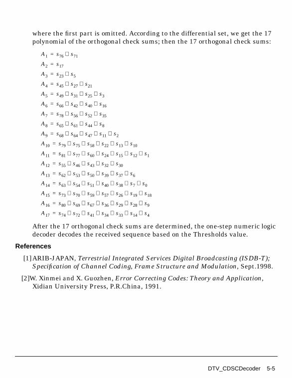
where the first part is omitted. According to the differential set, we get the 17polynomial of the orthogonal check sums; then the 17 orthogonal check sums:
After the 17 orthogonal check sums are determined, the one-step numeric logicdecoder decodes the received sequence based on the Thresholds value.
References
[1]ARIB-JAPAN, Terrestrial Integrated Services Digital Broadcasting (ISDB-T);Specification of Channel Coding, Frame Structure and Modulation, Sept.1998.
[2]W. Xinmei and X. Guozhen, Error Correcting Codes: Theory and Application,Xidian University Press, P.R.China, 1991.
A1 s76 s71⊕=
A2 s17=
A3 s23 s5⊕=
A4 s45 s27 s21⊕ ⊕=
A5 s49 s31 s25 s3⊕ ⊕ ⊕=
A6 s66 s42 s40 s16⊕ ⊕ ⊕=
A7 s78 s56 s52 s35⊕ ⊕ ⊕=
A8 s65 s61 s44 s8⊕ ⊕ ⊕=
A9 s68 s64 s47 s11 s2⊕ ⊕ ⊕ ⊕=
A10 s79 s75 s58 s22 s13 s10⊕ ⊕ ⊕ ⊕ ⊕=
A11 s81 s77 s60 s24 s15 s12 s1⊕ ⊕ ⊕ ⊕ ⊕ ⊕=
A12 s55 s46 s43 s32 s30⊕ ⊕ ⊕ ⊕=
A13 s62 s53 s50 s39 s37 s6⊕ ⊕ ⊕ ⊕ ⊕=
A14 s63 s54 s51 s40 s38 s7 s0⊕ ⊕ ⊕ ⊕ ⊕ ⊕=
A15 s73 s70 s59 s57 s26 s19 s18⊕ ⊕ ⊕ ⊕ ⊕ ⊕=
A16 s80 s69 s67 s36 s29 s28 s9⊕ ⊕ ⊕ ⊕ ⊕ ⊕=
A17 s74 s72 s41 s34 s33 s14 s4⊕ ⊕ ⊕ ⊕ ⊕ ⊕=
DTV_CDSCDecoder 5-5

ISDB-T Components
DTV_CarrierRotator
Description Particle rotation within segmentLibrary DTV, ISDB-TClass SDFDTV_CarrierRotator
Parameters
Pin Inputs
Pin Outputs
Notes/Equations
1. This model performs intra-segment carrier rotation for each segment infrequency interleaving.
2. This model implements the intra-segment rotation and permutation of theOFDM segment symbols shown in Figure 5-2.
Name Description Default Type Range
Carriers block length of particles forone segment
384 int 96, 192, 384†
StartPoint start particle number insegment
0 1 2 3 int array (-∞, ∞)
Phase initial phase of segmentsequence
0 int (-∞, ∞)
† Carriers = 96, 192, 384 for mode 1, 2, 3, respectively
Pin Name Description Signal Type
1 input symbols to be rotated anytype
Pin Name Description Signal Type
2 output rotated symbols anytype
5-6 DTV_CarrierRotator

S′(k + i mod Carriers) = Si, 0, k
0 ≤ i ≤ Carriers - 1
k is the segment number
Si, j, k denotes the complex data of the kth segment before inter-segmentinterleaving
S′i, j, kdenotes the complex data of the kth segment after inter-segmentinterleaving
Figure 5-2. Intra-Segment Carrier Rotation Interleaving
References
[1]ARIB-JAPAN, Terrestrial Integrated Services Digital Broadcasting (ISDB-T);Specification of Channel Coding, Framing Structure and Modulation,Sept.1998.
S′0,0,k S′1,0,k S′2,0,k_ _ _ S′95,0,k
S′(k mod 192),0,k_ _ _S′(k+1 mod 192),0,k S′(k+2 mod 192),0,k S′(k+191 mod 192),0,k
S′0,0,k S′1,0,k S′2,0,k_ _ _ S′95,0,k
S′(k mod 96),0,k_ _ _S′(k+1 mod 96),0,k S′(k+2 mod 96),0,k S′(k+95 mod 96),0,k
S′0,0,k S′1,0,k S′2,0,k_ _ _ S′383,0,k
S′(k mod 384),0,k_ _ _S′(k+1 mod 384),0,k S′(k+2 mod 384),0,k S′(k+383 mod 384),0,k
(a) Intra-segment carrier rotation for Mode 1
(b) Intra-segment carrier rotation for Mode 2
(c) Intra-segment carrier rotation for Mode 3
DTV_CarrierRotator 5-7

ISDB-T Components
DTV_CarrierScrambler
Description Carrier scrambler and descramblerLibrary DTV, ISDB-TClass SDFDTV_CarrierScrambler
Parameters
Pin Inputs
Pin Outputs
Notes/Equations
1. This model performs inter-segment carrier randomization in frequencyinterleaving for each segment.
Name Description Default Type Range
Carriers number of carriers for eachsegment in OFDMmodulation mode
96 int 96, 192, 384†
Option carrier option:Scramble,Descramble: Scramble,Descramble
Scramble enum
Sequence customized carriermapping index, or empty touse the ISDB defaults
int array [0, ∞)
† Carriers = 96, 192, 384 for mode 1, 2, 3, respectively
Pin Name Description Signal Type
1 input symbols to be randomized anytype
Pin Name Description Signal Type
2 output randomized symbols anytype
5-8 DTV_CarrierScrambler

2. This model assigns the OFDM symbols to each carrier within each segment in apre-defined permutation order. Carrier permutation mapping from input tooutput according to modulation mode is described in Table 5-1 throughTable 5-3. These mapping tables are used when Sequence is empty and Optionindicates scrambling or de-scrambling. A customized mapping table can be usedto implement a user-specified design, in which case Option is ignored.
Table 5-1. Intra-Segment Carrier Randomization for Mode 1From 0 1 2 3 4 5 6 7 8 9 10 11
To 80 93 63 92 94 55 17 81 6 51 9 85
From 12 13 14 15 16 17 18 19 20 21 22 23
To 89 65 52 15 73 66 46 71 12 70 18 13
From 24 25 26 27 28 29 30 31 32 33 34 35
To 95 34 1 38 78 59 91 64 0 28 11 4
From 36 37 38 39 40 41 42 43 44 45 46 47
To 45 35 16 7 48 22 23 77 56 19 8 36
From 48 49 50 51 52 53 54 55 56 57 58 59
To 39 61 21 3 26 69 67 20 74 86 72 25
From 60 61 62 63 64 65 66 67 68 69 70 71
To 31 5 49 42 54 87 43 60 29 2 76 84
From 72 73 74 75 76 77 78 79 80 81 82 83
To 83 40 14 79 27 57 44 37 30 68 47 88
From 84 85 86 87 88 89 90 91 92 93 94 95
To 75 41 90 10 33 32 62 50 58 82 53 24
values indicate carrier indexing; complex data indicated by the From carrier index is carried by the To carrier index
Table 5-2. Intra-Segment Carrier Randomization for Mode 2From 0 1 2 3 4 5 6 7 8 9 10 11
To 98 35 67 116 135 17 5 93 73 168 54 143
From 12 13 14 15 16 17 18 19 20 21 22 23
To 43 74 165 48 37 69 154 150 107 76 176 79
From 24 25 26 27 28 29 30 31 32 33 34 35
To 175 36 28 78 47 128 94 163 184 72 142 2
From 36 37 38 39 40 41 42 43 44 45 46 47
To 86 14 130 151 114 68 46 183 122 112 180 42
From 48 49 50 51 52 53 54 55 56 57 58 59
To 105 97 33 134 177 84 170 45 187 38 167 10
DTV_CarrierScrambler 5-9

ISDB-T Components
From 60 61 62 63 64 65 66 67 68 69 70 71
To 189 51 117 156 161 25 89 125 139 24 19 57
From 72 73 74 75 76 77 78 79 80 81 82 83
To 71 39 77 191 88 85 0 162 181 113 140 61
From 84 85 86 87 88 89 90 91 92 93 94 95
To 75 82 101 174 118 20 136 3 121 190 120 92
From 96 97 98 99 100 101 102 103 104 105 106 107
To 160 52 153 127 65 60 133 147 131 87 22 58
From 108 109 110 111 112 113 114 115 116 117 118 119
To 100 111 141 83 49 132 12 155 146 102 164 66
From 120 121 122 123 124 125 126 127 128 129 130 131
To 1 62 178 15 182 96 80 119 23 6 166 56
From 132 133 134 135 136 137 138 139 140 141 142 143
To 99 123 138 137 21 145 185 18 70 129 95 90
From 144 145 146 147 148 149 150 151 152 153 154 155
To 149 109 124 50 11 152 4 31 172 40 13 32
From 156 157 158 159 160 161 162 163 164 165 166 167
To 55 159 41 8 7 144 16 26 173 81 44 103
From 168 169 170 171 172 173 174 175 176 177 178 179
To 64 9 30 157 126 179 148 63 188 171 106 104
From 180 181 182 183 184 185 186 187 188 189 190 191
To 158 115 34 186 29 108 53 91 169 110 27 59
values indicate carrier indexing; complex data indicated by the From carrier index is carried by the To carrier index
Table 5-3. Intra-Segment Carrier Randomization for Mode 3From 0 1 2 3 4 5 6 7 8 9 10 11
To 62 13 371 11 285 336 365 220 226 92 56 46
From 12 13 14 15 16 17 18 19 20 21 22 23
To 120 175 298 352 172 235 53 164 368 187 125 82
From 24 25 26 27 28 29 30 31 32 33 34 35
To 5 45 173 258 135 182 141 273 126 264 286 88
From 36 37 38 39 40 41 42 43 44 45 46 47
To 233 61 249 367 310 179 155 57 123 208 14 227
From 48 49 50 51 52 53 54 55 56 57 58 59
To 100 311 205 79 184 185 328 77 115 277 112 20
Table 5-2. Intra-Segment Carrier Randomization for Mode 2 (continued)
5-10 DTV_CarrierScrambler

From 60 61 62 63 64 65 66 67 68 69 70 71
To 199 178 143 152 215 204 139 234 358 192 309 183
From 72 73 74 75 76 77 78 79 80 81 82 83
To 81 129 256 314 101 43 97 324 142 157 90 214
From 84 85 86 87 88 89 90 91 92 93 94 95
To 102 29 303 363 261 31 22 52 305 301 293 177
From 96 97 98 99 100 101 102 103 104 105 106 107
To 116 296 85 196 191 114 58 198 16 167 145 119
From 108 109 110 111 112 113 114 115 116 117 118 119
To 245 113 295 193 232 17 108 283 246 64 237 189
From 120 121 122 123 124 125 126 127 128 129 130 131
To 128 373 302 320 239 335 356 39 347 351 73 158
From 132 133 134 135 136 137 138 139 140 141 142 143
To 276 243 99 38 287 3 330 153 315 117 289 213
From 144 145 146 147 148 149 150 151 152 153 154 155
To 210 149 383 337 339 151 241 321 217 30 334 161
From 156 157 158 159 160 161 162 163 164 165 166 167
To 322 49 176 359 12 346 60 28 229 265 288 225
From 168 169 170 171 172 173 174 175 176 177 178 179
To 382 59 181 170 319 341 86 251 133 344 361 109
From 180 181 182 183 184 185 186 187 188 189 190 191
To 44 369 268 257 323 55 317 381 121 360 260 275
From 192 193 194 195 196 197 198 199 200 201 202 203
To 190 19 63 18 248 9 240 211 150 230 332 231
From 204 205 206 207 208 209 210 211 212 213 214 215
To 71 255 350 355 83 87 154 218 138 269 348 130
From 216 217 218 219 220 221 222 223 224 225 226 227
To 160 278 377 216 236 308 223 254 25 98 300 201
From 228 229 230 231 232 233 234 235 236 237 238 239
To 137 219 36 325 124 66 353 169 21 35 107 50
From 240 241 242 243 244 245 246 247 248 249 250 251
To 106 333 326 262 252 271 263 372 136 0 366 206
From 252 253 254 255 256 257 258 259 260 261 262 263
To 159 122 188 6 284 96 26 200 197 186 345 340
From 264 265 266 267 268 269 270 271 272 273 274 275
To 349 103 84 228 212 2 67 318 1 74 342 166
Table 5-3. Intra-Segment Carrier Randomization for Mode 3 (continued)
DTV_CarrierScrambler 5-11

ISDB-T Components
References
[1]ARIB-JAPAN, Terrestrial Integrated Services Digital Broadcasting (ISDB-T);Specification of Channel Coding, Framing Structure and Modulation,Sept.1998.
From 276 277 278 279 280 281 282 283 284 285 286 287
To 194 33 68 267 111 118 140 195 105 202 291 259
From 288 289 290 291 292 293 294 295 296 297 298 299
To 23 171 65 281 24 165 8 94 222 331 34 238
From 300 301 302 303 304 305 306 307 308 309 310 311
To 364 376 266 89 80 253 163 280 247 4 362 379
From 312 313 314 315 316 317 318 319 320 321 322 323
To 290 279 54 78 180 72 316 282 131 207 343 370
From 324 325 326 327 328 329 330 331 332 333 334 335
To 306 221 132 7 148 299 168 224 48 47 357 313
From 336 337 338 339 340 341 342 343 344 345 346 347
To 75 104 70 147 40 110 374 69 146 37 375 354
From 348 349 350 351 352 353 354 355 356 357 358 359
To 174 41 32 304 307 312 15 272 134 242 203 209
From 360 361 362 363 364 365 366 367 368 369 370 371
To 380 162 297 327 10 93 42 250 156 338 292 144
From 372 373 374 375 376 377 378 379 380 381 382 383
To 378 294 329 127 270 76 95 91 244 274 27 51
Values indicate carrier indexed, and complex data indicated by the carrier index From is carried by the carrier index To
Table 5-3. Intra-Segment Carrier Randomization for Mode 3 (continued)
5-12 DTV_CarrierScrambler

DTV_ChEstimator
Description OFDM symbol channel estimator and channel interpolator for ISDB-TLibrary DTV, ISDB-TClass SDFDTV_ChEstimator
Parameters
Name Description Default Type Range
Layers number of layers 1 int 1 for 1-layer; 2 for 2-layer; 3 for 3-layersystems
Carriers number of carriers in oneOFDM symbol
432 int 108 for mode 1 216 for mode 2; 432 for mode 3
Segments number of segments ineach layer
13 int array [1, 13]
InSequence segment sequence at input 11 9 7 5 3 1 0 2 46 8 10 12
int array "0, 1,...,Nseg-1]"
OutSequence segment sequence atoutput
0 1 2 3 4 5 6 7 8 910 11 12
int array "... , 1,0,2,..."
Order FFT points=2^Order 13 int [1, ∞)
CPnumber number of continual pilotsin each segment for eachlayer
0 int array 1, 0
SPnumber number of scattered pilotsin each segment
36 int array [1, ∞)
SPperiod distance in carriersbetween nearby scatteredpilots in each segments foreach layer
12 int array [0, ∞)
SPstart start position of scatteredpilots in carriers
0 int array [1, ∞)
SPoffset offset value of SPstart ineach symbol
3 int array [0, ∞)
SPphase initial phase of scatteredpilots for each layer
0 int array [0, SPperiod/SPoffset[i]-1)]
DTV_ChEstimator 5-13

ISDB-T Components
Pin Inputs
Pin Outputs
Notes/Equations
1. This model adjusts the transmission spectrum, linear channel estimation,channel interpolation based on the pilot channel. It outputs the segments dataand corresponding subchannel estimation according to the OutSequence.
2. Segments is the array of number of segments in each layer. Segments ≥1, butthe sum of each component in Segments ≤13. For example: Segments= "1,5,6" iscorrect; Segments= "0,7" or Segments= "1,7,8" are not correct.
3. InSequence is [0, NSeg-1], where Nseg=Segments[0]+....+Segments[Layer-1] isthe sum of each component in Segments. According to ISDB-T, the InSequenceis "0,1,2, ... , Nseg-1" after Segments is determined.
4. OutSequence is [0,Nseg-1]. According to ISDB-T, the OutSequence is"... , 1, 0, 2, ..." after Segments is determined. For example: if Segments= "1,4",OutSequence is "3,1,0,2,4"; if Segments= "1,4,5", OutSequence is"9,7,5,3,1,0,2,4,6,8".
5. Order is the order of FFT. It must satisfy 2Order ≥ Carriers × Nseg.
6. CPnumber is 0 or 1 according to ISDB-T. If the modulation mode is DQPSK inone layer, its corresponding component in CPnumber is 1 per one segment,otherwise, its corresponding component in CPnumber is 0. For example: in a2-layer system, the first layer is DQPSK modulation, the second layer is16-QAM modulation, the CPnumber= "1, 0".
7. SPnumber = 0, 9, 18 or 36 according to ISDB-T. If the modulation mode is:
• differential modulation in one layer, its corresponding component inSPnumber is 0
Pin Name Description Signal Type
1 input output signal from FFT complex
Pin Name Description Signal Type
2 output segments data whose order is OutSequence complex
3 Coef channel estimation complex
5-14 DTV_ChEstimator

• coherent modulation in one layer, its corresponding component in SPnumberis 9, 18 or 36 of mode 1, mode 2, or mode 3 per one segment, respectively.
For example, in a 3-layer mode 3 system, the first and third layers are coherentmodulation and the second layer is differential modulation; SPnumber= "36, 0,36".
8. SPperiod = 0 or 12 according to ISDB-T. If the modulation mode is:
• differential modulation in one layer, its corresponding component inSPperiod is 0
• coherent modulation in one layer, its corresponding component in SPperiod is12.
For example, in a 3-layer mode 3 system, the first and third layers are coherentmodulation and the second layer is differential modulation; SPperiod= "12, 0,12".
9. SPstart = 0 according to ISDB-T.
10. SPoffset = 0 or 3 according to ISDB-T. If the modulation mode is:
• differential modulation in one layer, its corresponding component in SPoffsetis 0
• coherent modulation in one layer, its corresponding component in SPoffset is3
For a example, in a 3-layer mode 3 system, the first and third layers arecoherent modulation and the second layer is differential modulation; SPoffset="3, 0, 3".
11. SPphase = 3 in the OFDM receiver if the modulation mode of the correspondinglayer is coherent modulation (because DTV_MLEstimator makes one OFDMsymbol delay); otherwise, SPphase = 0.
For a example, in a 3-layer mode 3 system, the first and third layers arecoherent modulation and the second layer is differential modulation; SPphase="3, 0, 3".
12. Using IntState of Carriers, CPnumber and SPnumber, this model determinesthe number of CP (continual pilot) and SP (scattered pilots) in each segment inevery layer. According to ISDB-T, if the modulation mode in one layer is:
• for differential modulation there is one CP in every segment; there are noSPs in any segment.
DTV_ChEstimator 5-15

ISDB-T Components
• for coherent modulation there are 9, 18, 36 SPs in each segment in one layer,for mode 1, 2, and 3, respectively; there are no CPs in any segment.
PRBS sequences in each segment are generated according to Figure 5-3 and theinitial sets of PRBS register in Table 5-4. The PRBS in initialized so that thefirst output bit from the PRBS coincides with the first active carrier. A newvalue is generated by the PRBS on every carrier used in each segment (whetheror not it is a pilot).
The position of one CP in the differential modulation segment is always zero.Positions of scattered pilots in the coherent modulation segments are generatedas follows. For the symbol of index l (ranging from 0 to 203), carriers for whichindex k belongs to subset
are SP positions, where i is 0, 1, 2, corresponding to the coherent modulationsegments layers. Five parameters control the SP positions.
• SPnumber determines the number of scattered pilots in each segment: 9 inmode 1 (Length=108), 18 in mode 2 (Length=216), and 36 in mode 3(Length=432).
• SPperiod =12, SPstart = 0, SPoffset = 3 and SPphase=0 in all modesaccording to ISDB-T.
After determining all CP and SP positions in each corresponding segment inevery layer, we get the pilots value from the PRBS sequence. So, we can get thechannel estimation in this CP and SP pilots.
where h(i) is the channel estimation x(i) is the received signal from channelafter FFT and PilotValue(i) is the PRBS value corresponding to CP and SPposition in each segment.
After getting the subchannel estimation in the CP and SP pilots position, weuse the linear interpolation algorithm to get all active subchannel estimation:
where i ≤ h ≤ j, h(i), and h(j) are the subchannel estimation of the CP or SPpilots.
k 3 l mod 4× 12p+= p integer p 0 k 0 Length Segments i[ ]×[ , ]∈,≥,
h i( ) x i( )PilotValue i( )---------------------------------------=
h k( ) αh i( ) 1 α–( )h j( )+=
α j k–j i–------------=
5-16 DTV_ChEstimator

The transmission spectrum adjustment is made in DTV_LoadIFFTBuff. In thereceiver, the transmission spectrum must be inversed. InSequence andOutSequence must be identical to DTV_LoadIFFTBuff. The layer segment datais output by the order of OutSequence. Inserted zeros in DTV_LoadIFFTBuffare discarded. The active carriers and its corresponding subchannel carriers areoutput for use in the equalizer model.
Figure 5-3. Generation of PRBS Sequence
References
[1]ARIB-JAPAN, Terrestrial Integrated Services Digital Broadcasting (ISDB-T);Specification of Channel Coding, Framing Structure and Modulation,Sept.1998.
Table 5-4. Initial Sets of PRBS Register
SegmentNumber Initial Sets for Mode 1 † Initial Sets for Mode 2 † Initial Sets for Mode 3 †
11 1 1 1 1 1 1 1 1 1 1 1 1 1 1 1 1 1 1 1 1 1 1 1 1 1 1 1 1 1 1 1 1 1
9 1 1 0 1 1 0 0 1 1 1 1 0 1 1 0 1 0 1 1 1 1 0 1 1 0 1 1 1 0 0 1 0 1
7 0 1 1 0 1 0 1 1 1 1 0 1 1 0 1 1 1 0 0 1 0 1 1 0 0 1 0 1 0 0 0 0 0
5 0 1 0 0 0 1 0 1 1 1 0 1 1 0 0 1 0 0 0 0 1 0 0 1 1 1 0 0 0 1 0 0 1
3 1 1 0 1 1 1 0 0 1 0 1 1 0 0 1 0 1 0 0 0 0 0 0 0 1 0 0 0 1 1 0 0 1
1 0 0 1 0 1 1 1 1 0 1 0 0 0 0 0 1 0 1 1 0 0 0 1 1 1 0 0 1 1 0 1 1 0
0 1 1 0 0 1 0 0 0 0 1 0 0 1 1 1 0 0 0 1 0 0 1 0 0 1 0 0 0 0 1 0 1 1
2 0 0 0 1 0 0 0 0 1 0 0 0 0 0 0 0 1 0 0 1 0 0 1 1 1 0 0 1 1 1 1 0 1
4 1 0 0 1 0 1 0 0 0 0 0 0 0 1 0 0 0 1 1 0 0 1 0 1 1 0 1 0 1 0 0 1 1
6 1 1 1 1 0 1 1 0 0 0 0 0 1 1 0 0 1 1 1 0 0 1 1 0 1 1 1 0 1 0 0 1 0
8 0 0 0 0 1 0 1 1 0 0 0 1 1 1 0 0 1 1 0 1 1 0 0 1 1 0 0 0 1 0 0 1 0
10 1 0 1 0 0 1 0 0 1 1 1 0 0 1 0 1 0 1 0 0 0 1 1 1 1 1 0 1 0 0 1 0 1
12 0 1 1 1 0 0 0 1 0 0 1 0 0 1 0 0 0 0 1 0 1 1 0 0 0 1 0 0 1 1 1 0 0
†Degree from 0 to 10 in Figure 5-3.
D D D D D D D D
0 1 2 3 4 5 6 7
D D D
8 9 10
+
Degree:
g(x) = x17 + x9 + I
Output = Wi
DTV_ChEstimator 5-17

ISDB-T Components
DTV_DemuxCohSegs
Description OFDM de-segment for coherent modulationLibrary DTV, ISDB-TClass SDFDTV_DemuxCohSegs
Parameters
Pin Inputs
Name Description Default Type Range
Carriers number of carriers in onesegment
432 int 108 for mode 1; 216 for mode 2; 432 for mode 3
Segments number of segments 1 int [1, 13]
Start_Seg initial number of segment(0 to Segments-1)
0 int [0, 12]
SPnumber number of scattered pilotsin each segment
36 int [0, ∞)†
SPperiod distance in carriersbetween nearby scatteredpilots
12 int (0, ∞)††
SPstart start position of scatteredpilots in carriers
0 int [0, ∞)††
SPoffset offset value of SPstart ineach symbol
3 int [0, ∞)††
SPphase initial phase of scatteredpilots
3 int [0,SPperiod/SPoffset-1]†††
† SPnumber = 9 for mode 1, 18 for mode 2, 36 for mode 3, per segment in ISDB-T systems.†† SPperiod = 12, SPstart = 0, SPoffset = 3 in ISDB-T systems.††† SPphase=3 in the OFDM receiver (because DTV_MLEstimator makes one OFDM symbol delay)
Pin Name Description Signal Type
1 input received equalized signal complex
5-18 DTV_DemuxCohSegs

Pin Outputs
Notes/Equations
1. This model demultiplexes coherent modulation OFDM segments (such asQPSK, 16-QAM, and 64-QAM modulation) into TSP (transport stream packet)data, TMCC (transmission and multiplexing configuration control) data, AC(auxiliary channel) data according to Figure 5-4 and Table 5-5.
2. IntState of Carriers determines the number of TMCC and AC in each segment.Then, IntState of Start_Seg and Segments determines the TMCC and ACpositions in each corresponding segment according to Table 5-5.
The PRBS sequences in each segment are generated according to Figure 5-5and the initial sets of PRBS register in Table 5-6. The PRBS in initialized sothat the first output bit from the PRBS coincides with the first active carrier. Anew value is generated by the PRBS on every used carrier in each segment(whether or not it is a pilot).
Positions of the corresponding scattered pilots are generated as follows.
For the symbol of index l (ranging from 0 to 203), carriers for which index kbelongs to subset
are scattered pilot positions.
Five parameters control the scattered pilots positions.
• SPnumber determines the number of scattered pilots in each segment: it is 9in mode 1 (Length=108); 18 in mode 2 (Length=216); and, 36 in mode 3(Length=432).
• SPperiod= 12, SPstart=0, SPoffset=3 and SPphase = 0 in the three modesaccording to ISDB-T.
After determining TMCC, AC, and SP positions in each corresponding segmentand the value of the PRBS sequence in all the active carriers in each segment,
Pin Name Description Signal Type
2 output TSP data output complex
3 TMCC TMCC data output complex
4 AC AC data output complex
k 3 l mod 4× 12p+= p integer p 0 k 0 Length Segments×[ , ]∈,≥,
DTV_DemuxCohSegs 5-19

ISDB-T Components
the model demultiplexes the input data into TMCC, AC, and TSP data.According to the TMCC position and the PRBS sequence, we can get the onlyone TMCC bit in each TMCC position, then the one transmitted TMCC bit isdetermined by the mean value of the TMCC positions.
where NTMCC is the number of TMCCs in one segment; PilotValue is the PRBSsequence in corresponding segment; x[i] is the input data.
AC data is:
Except for AC, TMCC, and SP positions, the remaining positions in one segmentare the TSP data positions.
TMCC 1NTMCC------------------------- x TMCCposition l[ ][ ]
PilotValue TMCCposition l[ ][ ]-----------------------------------------------------------------------------------------
l 1=
NTMCC
∑=
AC i[ ] x ACposition i[ ][ ]PilotValue ACposition i[ ][ ]-------------------------------------------------------------------------------=
Data i[ ] x i[ ]=
5-20 DTV_DemuxCohSegs

Figure 5-4. Structure of OFDM Segment for Coherent Modulation
TM
CC
AC
(A
C1)
0 1 2 3 4 5 6 7 8 9 10 11 12 Nc-1Carrier Number
OF
DM
Sym
bol N
umbe
r
0
1
23
4
203
202
201
200
SP
SP
SP
SP
SP
SP
SP
SP
SP
SP
SP
SP
S0,0 S1,0 S2,0 S3,0 S4,0 S5,0 S6,0 S7,0 S8,0 S9,0 S10,0
S0,1 S1,1 S2,1
S0,2 S1,2 S2,2
S0,3 S1,3 S2,3
S0,4 S1,4 S2,4
S3,1 S4,1 S5,1 S6,1 S7,1 S8,1 S9,1 S10,1 S11,1
S3,2 S4,2 S5,2
S3,3 S4,3 S5,3
S3,4 S4,4 S5,4
S6,3 S7,3 S8,3
S6,4 S7,4 S8,4
S6,2 S7,2 S8,2 S9,2 S10,2 S11,2
S9,3 S10,3 S11,3
S9,4 S10,4
S0,201 S1,201 S2,201 S3,201 S4,201 S5,201 S7,201S6,201 S8,201
S0,202 S1,202 S2,202 S3,202 S4,202 S5,202 S7,202S6,202 S8,202
S0,203 S1,203 S2,203 S3,203 S4,203 S5,203 S6,203 S7,203 S8,203
SNc-1,0
SNc-1,1
SNc-1,2
SNc-1,3
SNc-1,4
SNc-1,5
SNc-1,6
SNc-1,7
SNc-1,201
SNc-1,202
SNc-1,203
Si,j,k denotes complex data in the data segment after time and frequency interleaving.
Nc=108 for Mode1; 216 for Mode2; 432 for Mode 3
DTV_DemuxCohSegs 5-21

ISDB-T Components
Figure 5-5. Generation of PRBS Sequence
Table 5-5. Carrier Allocation of AC and TMCC for Coherent Modulation
Segment 11 9 7 5 3 1 0 2 4 6 8 10 12
Mode 1
AC1_1 10 53 61 11 20 74 35 76 4 40 8 7 98
AC1_2 28 83 100 101 40 100 79 97 89 89 64 89 101
TMCC_1 70 25 17 86 44 47 49 31 83 61 85 101 23
Mode 2
AC1_1 10 61 20 35 4 8 98 53 11 74 76 40 7
AC1_2 28 100 40 79 89 64 101 83 101 100 97 89 89
AC1_3 161 119 182 184 148 115 118 169 128 143 112 116 206
AC1_4 191 209 208 205 197 197 136 208 148 187 197 172 209
TMCC_1 70 17 44 49 83 85 23 25 86 47 31 61 101
TMCC_2 133 194 155 139 169 209 178 125 152 157 191 193 131
Mode 3
AC1_1 10 20 4 98 11 76 7 61 35 8 53 74 40
AC1_2 28 40 89 101 101 97 89 100 79 64 83 100 89
AC1_3 161 182 148 118 128 112 206 119 184 115 169 143 116
AC1_4 191 208 197 136 148 197 209 209 205 197 208 187 172
AC1_5 277 251 224 269 290 256 226 236 220 314 227 292 223
AC1_6 316 295 280 299 316 305 244 256 305 317 317 313 305
AC1_7 335 400 331 385 359 332 377 398 364 334 344 328 422
AC1_8 425 421 413 424 403 388 407 424 413 352 364 413 425
TMCC_1 70 44 83 23 86 31 101 17 49 85 25 47 61
TMCC_2 131 155 169 178 152 191 131 194 139 209 125 157 193
TMCC_3 233 265 301 241 263 277 286 260 299 239 302 247 317
TMCC_4 410 355 425 341 373 409 349 371 385 394 368 407 347
D D D D D D D D
0 1 2 3 4 5 6 7
D D D
8 9 10
+
Degree:
g(x) = x17 + x9 + I
Output = Wi
5-22 DTV_DemuxCohSegs

References
[1]ARIB-JAPAN, Terrestrial Integrated Services Digital Broadcasting (ISDB-T);Specification of Channel Coding, Framing Structure and Modulation,Sept.1998.
Table 5-6. Initial Sets of PRBS Register
Segment Initial Sets for Mode 1 † Initial Sets for Mode 2 † Initial Sets for Mode 3 †
11 1 1 1 1 1 1 1 1 1 1 1 1 1 1 1 1 1 1 1 1 1 1 1 1 1 1 1 1 1 1 1 1 1
9 1 1 0 1 1 0 0 1 1 1 1 0 1 1 0 1 0 1 1 1 1 0 1 1 0 1 1 1 0 0 1 0 1
7 0 1 1 0 1 0 1 1 1 1 0 1 1 0 1 1 1 0 0 1 0 1 1 0 0 1 0 1 0 0 0 0 0
5 0 1 0 0 0 1 0 1 1 1 0 1 1 0 0 1 0 0 0 0 1 0 0 1 1 1 0 0 0 1 0 0 1
3 1 1 0 1 1 1 0 0 1 0 1 1 0 0 1 0 1 0 0 0 0 0 0 0 1 0 0 0 1 1 0 0 1
1 0 0 1 0 1 1 1 1 0 1 0 0 0 0 0 1 0 1 1 0 0 0 1 1 1 0 0 1 1 0 1 1 0
0 1 1 0 0 1 0 0 0 0 1 0 0 1 1 1 0 0 0 1 0 0 1 0 0 1 0 0 0 0 1 0 1 1
2 0 0 0 1 0 0 0 0 1 0 0 0 0 0 0 0 1 0 0 1 0 0 1 1 1 0 0 1 1 1 1 0 1
4 1 0 0 1 0 1 0 0 0 0 0 0 0 1 0 0 0 1 1 0 0 1 0 1 1 0 1 0 1 0 0 1 1
6 1 1 1 1 0 1 1 0 0 0 0 0 1 1 0 0 1 1 1 0 0 1 1 0 1 1 1 0 1 0 0 1 0
8 0 0 0 0 1 0 1 1 0 0 0 1 1 1 0 0 1 1 0 1 1 0 0 1 1 0 0 0 1 0 0 1 0
10 1 0 1 0 0 1 0 0 1 1 1 0 0 1 0 1 0 1 0 0 0 1 1 1 1 1 0 1 0 0 1 0 1
12 0 1 1 1 0 0 0 1 0 0 1 0 0 1 0 0 0 0 1 0 1 1 0 0 0 1 0 0 1 1 1 0 0
†Degree from 0 to 10 in Figure 5-5.
DTV_DemuxCohSegs 5-23

ISDB-T Components
DTV_DemuxDiffSegs
Description OFDM de-segment for differential modulationLibrary DTV, ISDB-TClass SDFDTV_DemuxDiffSegs
Parameters
Pin Inputs
Pin Outputs
Notes/Equations
1. This model demultiplexes the differential modulation OFDM segments (such asDQPSK modulation) into TSP (transport stream packet) data, TMCC
Name Description Default Type Range
Carriers number of carriers in onesegment
432 int 108 for mode 1; 216 for mode 2; 432 for mode 3
Segments number of segments 1 int [1, 13]
Start_Seg initial number of segment(0 to Segments-1)
0 int [0, 12]
Pin Name Description Signal Type
1 input received equalized signal complex
Pin Name Description Signal Type
2 output TSP data output complex
3 TMCC TMCC data output complex
4 AC1 AC1 data output complex
5 AC2 AC2 data output complex
5-24 DTV_DemuxDiffSegs

(transmission and multiplexing configuration control) data, AC (auxiliarychannel) data according to Figure 5-6 and Table 5-7.
2. IntState of Carriers determines the number of TMCC, AC1, and AC2 in eachsegment. IntState of Start_Seg and Segments determine the TMCC, AC1, andAC2 positions in each corresponding segment according to Table 5-7.
The PRBS sequences in each segment are generated according to Figure 5-7and the initial sets of PRBS register in Table 5-8. The PRBS in initialized sothat the first output bit from the PRBS coincides with the first active carrier. Anew value is generated by the PRBS on every used carriers in each segments(whether or not it is a pilot).
After determining all TMCC, AC1, and AC2 positions in each correspondingsegment and the value of the PRBS sequence in all active carriers in eachsegment, the model demultiplexes the input data into TMCC, AC1, AC2, andTSP data. According to the TMCC position and the PRBS sequence, we can getthe only one TMCC bit in each TMCC position, then the one transmitted TMCCbit is determined by the mean value of those TMCC positions.
where NTMCC is the number of TMCCs in one segment; PilotValue is the PRBSsequence in corresponding segment; x[i] is the input data.
AC1 data is:
AC2 data is:
Except for the AC1, AC2 and TMCC data positions, the remaining positions inone segment are the TSP data positions. Data[i] = x[i].
TMCC 1NTMCC------------------------- x TMCCposition l[ ][ ]
PilotValue TMCCposition l[ ][ ]-----------------------------------------------------------------------------------------
l 1=
NTMCC
∑=
AC1 i[ ] x AC1position i[ ][ ]PilotValue AC1position i[ ][ ]-----------------------------------------------------------------------------------=
AC2 i[ ] x AC2position i[ ][ ]PilotValue AC2position i[ ][ ]-----------------------------------------------------------------------------------=
DTV_DemuxDiffSegs 5-25

ISDB-T Components
Figure 5-6. Structure of OFDM Segment for Differential Modulation
Figure 5-7. Generation of PRBS Sequence
S1,0
S1,1
S1,2
S1,3
S1,4
S1,5
S1,6
S1,7
S1,203
CP
TM
CC
AC
(A
C1,
AC
2)
0 1 2 Nc-1Carrier Number
OF
DM
Sym
bol N
umbe
r
0
1
23
4
203
SNc-1,0
SNc-1,1
SNc-1,2
SNc-1,3
SNc-1,4
SNc-1,5
SNc-1,6
SNc-1,7
SNc-1,203
Si,j,k denotes complex data in the data segment after time and frequency interleaving.
Nc=108 for Mode1; 216 for Mode2; 432 for Mode 3
567
S0,0
S0,1
S0,2
S0,3
S0,4
S0,5
S0,6
S0,7
S0,203
D D D D D D D D
0 1 2 3 4 5 6 7
D D D
8 9 10
+
Degree:
g(x) = x17 + x9 + I
Output = Wi
5-26 DTV_DemuxDiffSegs

Table 5-7. Carrier Allocation of CP, AC, and TMCC forDifferential Modulation
Segment 11 9 7 5 3 1 0 2 4 6 8 10 12
Mode 1
CP 0 0 0 0 0 0 0 0 0 0 0 0 0
AC1_1 10 53 61 11 20 74 35 76 4 40 8 7 98
AC1_2 28 83 100 101 40 100 79 97 89 89 64 89 101
AC2_1 3 3 29 28 23 30 3 5 13 72 36 25 10
AC2_2 45 15 41 45 63 81 72 18 93 95 48 30 30
AC2_3 59 40 84 81 85 92 85 57 98 100 52 42 55
AC2_4 77 58 93 91 105 103 89 92 102 105 74 104 81
TMCC_1 13 25 4 36 10 7 49 31 16 5 78 34 23
TMCC_2 50 63 7 48 28 25 61 39 30 10 82 48 37
TMCC_3 70 73 17 55 44 47 96 47 37 21 85 54 51
TMCC_4 83 80 51 59 47 60 99 65 74 44 98 70 68
TMCC_5 87 93 71 86 54 87 104 72 83 61 102 101 105
Mode 2
CP 0 0 0 0 0 0 0 0 0 0 0 0 0
AC1_1 10 61 20 35 4 8 98 53 11 74 76 40 7
AC1_2 28 100 40 79 89 64 101 83 101 100 97 89 89
AC1_3 161 119 182 184 148 115 118 169 128 143 112 116 206
AC1_4 191 209 208 205 197 197 136 208 148 187 197 172 209
AC2_1 3 29 23 3 13 36 10 3 28 30 5 72 25
AC2_2 45 41 63 72 93 48 30 15 45 81 18 95 30
AC2_3 59 84 85 85 98 52 55 40 81 92 57 100 42
AC2_4 77 93 105 89 102 74 81 58 91 103 92 105 104
AC2_5 108 108 108 108 108 108 108 108 108 108 108 108 108
AC2_6 111 136 138 113 180 133 111 137 131 111 121 144 118
AC2_7 123 153 189 126 203 138 153 149 171 180 201 156 138
AC2_8 148 189 200 165 208 150 167 192 193 193 206 160 163
AC2_9 166 199 211 200 213 212 185 201 213 197 210 182 189
TMCC_1 13 4 10 49 16 78 23 25 36 7 31 5 34
TMCC_2 50 7 28 61 30 82 37 63 48 25 39 10 48
TMCC_3 70 17 44 96 37 85 51 73 55 47 47 21 54
TMCC_4 83 51 47 99 74 98 68 80 59 60 65 44 70
TMCC_5 87 71 54 104 83 102 105 93 86 87 72 61 101
DTV_DemuxDiffSegs 5-27

ISDB-T Components
TMCC_6 133 144 115 139 113 142 121 112 118 157 124 186 131
TMCC_7 171 156 133 147 118 156 158 115 136 169 138 190 145
TMCC_8 181 163 155 155 129 162 178 125 152 204 145 193 159
TMCC_9 188 167 168 173 152 178 191 159 155 207 182 206 176
TMCC_10 201 194 195 180 169 209 195 179 162 212 191 210 213
Mode 3
CP 0 0 0 0 0 0 0 0 0 0 0 0 0
AC1_1 10 20 4 98 11 76 7 61 35 8 53 74 40
AC1_2 28 40 89 101 101 97 89 100 79 64 83 100 89
AC1_3 161 182 148 118 128 112 206 119 184 115 169 143 116
AC1_4 191 208 197 136 148 197 209 209 205 197 208 187 172
AC1_5 277 251 224 269 290 256 226 236 220 314 227 292 223
AC1_6 316 295 280 299 316 305 244 256 305 317 317 313 305
AC1_7 335 400 331 385 359 332 377 398 364 334 344 328 422
AC1_8 425 421 413 424 403 388 407 424 413 352 364 413 425
AC2_1 3 23 13 10 28 5 25 29 3 36 3 30 72
AC2_2 45 63 93 30 45 18 30 41 72 48 15 81 95
AC2_3 59 85 98 55 81 57 42 84 85 52 40 92 100
AC2_4 77 105 102 81 91 92 104 93 89 74 58 103 105
AC2_5 108 108 108 108 108 108 108 108 108 108 108 108 108
AC2_6 111 138 180 111 131 121 118 136 113 133 137 111 144
AC2_7 123 189 203 153 171 201 138 153 126 138 149 180 156
AC2_8 148 200 208 167 193 206 163 189 165 150 192 193 160
AC2_9 166 211 213 185 213 210 189 199 200 212 201 197 182
AC2_10 216 216 216 216 216 216 216 216 216 216 216 216 216
AC2_11 245 219 252 219 246 288 219 239 229 226 244 221 241
AC2_12 257 288 264 231 297 311 261 279 309 246 261 234 246
AC2_13 300 301 268 256 308 316 275 301 314 271 297 273 258
AC2_14 309 305 290 274 319 321 293 321 318 297 307 308 320
AC2_15 324 324 324 324 324 324 324 324 324 324 324 324 324
AC2_16 352 329 349 353 327 360 327 354 396 327 347 337 334
AC2_17 369 342 354 365 396 372 339 405 419 369 387 417 354
AC2_18 405 381 366 408 409 376 364 416 424 383 409 422 379
AC2_19 415 416 428 417 413 398 382 427 429 401 429 426 405
Table 5-7. Carrier Allocation of CP, AC, and TMCC forDifferential Modulation (continued)
Segment 11 9 7 5 3 1 0 2 4 6 8 10 12
5-28 DTV_DemuxDiffSegs

TMCC_1 13 10 16 23 36 31 34 4 49 78 25 7 5
TMCC_2 50 28 30 37 48 39 48 7 61 82 63 25 10
TMCC_3 70 44 37 51 55 47 54 17 96 85 73 47 21
TMCC_4 83 47 74 68 59 65 70 51 99 98 80 60 44
TMCC_5 87 54 83 105 86 72 101 71 104 102 93 87 61
TMCC_6 133 115 113 121 118 124 131 144 139 142 112 157 186
TMCC_7 171 133 118 158 136 138 145 156 147 156 115 169 190
TMCC_8 181 155 129 178 152 145 159 163 155 162 125 204 193
TMCC_9 188 168 152 191 155 182 176 167 173 178 159 207 206
TMCC_10 201 195 169 195 162 191 213 194 180 209 179 212 210
TMCC_11 220 265 294 241 223 221 229 226 232 239 252 247 250
TMCC_12 223 277 298 279 241 226 266 244 246 253 264 255 264
TMCC_13 233 312 301 289 263 237 286 260 253 267 271 263 270
TMCC_14 267 315 314 296 276 260 299 263 290 284 275 281 286
TMCC_15 287 320 318 309 303 277 303 270 299 321 302 288 317
TMCC_16 360 355 358 328 373 402 349 331 329 337 334 340 347
TMCC_17 372 363 372 331 385 406 387 349 334 374 352 354 361
TMCC_18 379 371 378 341 420 409 397 371 345 394 368 361 375
TMCC_19 383 389 394 375 423 422 404 384 368 407 371 398 392
TMCC_20 410 396 425 395 428 426 417 411 385 411 378 407 429
Table 5-8. Initial Sets of PRBS Register
Segment Initial Sets for Mode 1 † Initial Sets for Mode 2 † Initial Sets for Mode 3 †
11 1 1 1 1 1 1 1 1 1 1 1 1 1 1 1 1 1 1 1 1 1 1 1 1 1 1 1 1 1 1 1 1 1
9 1 1 0 1 1 0 0 1 1 1 1 0 1 1 0 1 0 1 1 1 1 0 1 1 0 1 1 1 0 0 1 0 1
7 0 1 1 0 1 0 1 1 1 1 0 1 1 0 1 1 1 0 0 1 0 1 1 0 0 1 0 1 0 0 0 0 0
5 0 1 0 0 0 1 0 1 1 1 0 1 1 0 0 1 0 0 0 0 1 0 0 1 1 1 0 0 0 1 0 0 1
3 1 1 0 1 1 1 0 0 1 0 1 1 0 0 1 0 1 0 0 0 0 0 0 0 1 0 0 0 1 1 0 0 1
1 0 0 1 0 1 1 1 1 0 1 0 0 0 0 0 1 0 1 1 0 0 0 1 1 1 0 0 1 1 0 1 1 0
0 1 1 0 0 1 0 0 0 0 1 0 0 1 1 1 0 0 0 1 0 0 1 0 0 1 0 0 0 0 1 0 1 1
2 0 0 0 1 0 0 0 0 1 0 0 0 0 0 0 0 1 0 0 1 0 0 1 1 1 0 0 1 1 1 1 0 1
4 1 0 0 1 0 1 0 0 0 0 0 0 0 1 0 0 0 1 1 0 0 1 0 1 1 0 1 0 1 0 0 1 1
.†Degree from 0 to 10 in Figure 5-7
Table 5-7. Carrier Allocation of CP, AC, and TMCC forDifferential Modulation (continued)
Segment 11 9 7 5 3 1 0 2 4 6 8 10 12
DTV_DemuxDiffSegs 5-29

ISDB-T Components
References
[1]ARIB-JAPAN, Terrestrial Integrated Services Digital Broadcasting (ISDB-T);Specification of Channel Coding, Framing Structure and Modulation,Sept.1998.
6 1 1 1 1 0 1 1 0 0 0 0 0 1 1 0 0 1 1 1 0 0 1 1 0 1 1 1 0 1 0 0 1 0
8 0 0 0 0 1 0 1 1 0 0 0 1 1 1 0 0 1 1 0 1 1 0 0 1 1 0 0 0 1 0 0 1 0
10 1 0 1 0 0 1 0 0 1 1 1 0 0 1 0 1 0 1 0 0 0 1 1 1 1 1 0 1 0 0 1 0 1
12 0 1 1 1 0 0 0 1 0 0 1 0 0 1 0 0 0 0 1 0 1 1 0 0 0 1 0 0 1 1 1 0 0
Table 5-8. Initial Sets of PRBS Register (continued)
Segment Initial Sets for Mode 1 † Initial Sets for Mode 2 † Initial Sets for Mode 3 †
.†Degree from 0 to 10 in Figure 5-7
5-30 DTV_DemuxDiffSegs

DTV_DemuxTMCC
Description TMCC bit decomposer into 20 and 184 bits)Library DTV, ISDB-TClass SDFDTV_DemuxTMCC
Parameters
Pin Inputs
Pin Outputs
Notes/Equations
1. This model demultiplexes the 204 received transmission and multiplexingconfiguration control bits in ISDB-T systems.
2. According to ISDB-T, the first bit B0 is the initialization bit, so this bit isdiscarded.
B1 − B16, a 16-bit synchronization sequence, takes w0 and w1 (the inverse ofw0) in turn in every frame. This model outputs this 16-bit synchronizationsequence.
Name Description Default Type Range
Length length of TMCC format 204 int 204
Pin Name Description Signal Type
1 input received equalized signal int
Pin Name Description Signal Type
2 Sync synchronization of TMCC output int
3 Desc segment descriptor output int
4 Info coded TMCC information int
DTV_DemuxTMCC 5-31

ISDB-T Components
B17 − B19 represent the segment descriptor.
B20 − B203 include TMCC information (102 bits) and 82-bit parity bits; these184 bits need CDSC decoding.
References
[1]ARIB-JAPAN, Terrestrial Integrated Services Digital Broadcasting (ISDB-T);Specification of Channel Coding, Framing Structure and Modulation,Sept.1998.
5-32 DTV_DemuxTMCC

DTV_InterSegInterlv
Description Inter-segment interleaving of OFDM symbolsLibrary DTV, ISDB-TClass SDFDTV_InterSegInterlv
Parameters
Pin Inputs
Pin Outputs
Notes/Equations
1. This model performs inter-segment symbol interleaving among all segmentswithin the differential or coherent modulation layer.
2. The inter-segment interleaving is carried out among differential modulation(DQPSK) segments and coherent modulation (QPSK, 16-QAM, and 64-QAM) asshown in Figure 5-8.
Name Description Default Type Range
Segments depth of block interleaver 4 int [1, 13]
Carriers width of block interleaver 384 int 96, 192,384
Option operating option:Interleaving,Deinterleaving: Interleave,Deinterleave
Interleave enum
Pin Name Description Signal Type
1 input input symbols to be interleaved anytype
Pin Name Description Signal Type
2 output output symbols after interleaved anytype
DTV_InterSegInterlv 5-33

ISDB-T Components
Figure 5-8. Inter-Segment Interleaver
S0,0,0= S0
Data SegmentNo. 0
Data SegmentNo. 1
Data SegmentNo. 2
S1,0,0= S1
S95,0,0= S95
S0,0,1= S96
S1,0,1= S97
S95,0,1= S191
S0,0,2= S192
S1,0,2= S193
S95,0,2= S287
S0,0,n-1= S96(n-1)
S1,0,n-1 S95,0,n-1= S96n-1
Data SegmentNo. n-1
= S96(n-1)+1
S0
Data SegmentNo. 0
Data SegmentNo. 1
Data SegmentNo. 2
S1 Sn+1 S95n+1 S2 Sn+2 S95n+2 Sn-1 S96n-1
Data SegmentNo. n-1
S2n-1
S0,0,0= S0
Data SegmentNo. 0
Data SegmentNo. 1
Data SegmentNo. 2
S1,0,0= S1
S191,0,0= S191
S1,0,1= S192
S1,0,1= S193
S191,0,1= S383
S0,0,2= S384
S1,0,2= S385
S191,0,2= S575
S0,0,n-1= S192(n-1)
S1,0,n-1 S191,0,n-1= S192n-1
Data SegmentNo. n-1
= S192(n-1)+1
Sn S95n
S0
Data SegmentNo. 0
Data SegmentNo. 1
Data SegmentNo. 2
S1 Sn+1 S191n+1 S2 Sn+2 S191n+2 Sn-1 S192n-1
Data SegmentNo. n-1
S2n-1Sn S191n
Allocation of Complex Data before Inter-Segment Interleaving
Allocation of Complex Data before Inter-Segment Interleaving
Allocation of Complex Data after Inter-Segment Interleaving
Allocation of Complex Data after Inter-Segment Interleaving
Inter-Segment Interleaver for Mode 1
Inter-Segment Interleaver for Mode 2
whereSi,j,k demotes complex dataof OFDM segment.
5-34 DTV_InterSegInterlv

DTV_ISDBDemodulation
Description ISDB-T demapper and deinterleaverLibrary DTV, ISDB-T
Parameters
Pin Inputs
Pin Outputs
Notes/Equations
1. This subnetwork model performs hard-decision de-mapping and bit-wisede-interleaving for an ISDB-T receiver.
The schematic for this subnetwork is shown in Figure 5-9.
Name Description Default Type Range
Mode transmission mode: Mode1, Mode 2, Mode 3
Mode 1 enum
MappingMode signal constellations andmapping: DQPSK, QPSK,QAM-16, QAM-64
DQPSK enum
Segments number of segments perlayer
13 int [1, 13]
Pin Name Description Signal Type
1 In input complex
Pin Name Description Signal Type
2 Out output real
DTV_ISDBDemodulation 5-35

ISDB-T Components
Figure 5-9. DTV_ISDBDemodulation Schematic
2. For coherent transmission, the demapper works in a carrier-wise manner; fordifferential transmission (DQPSK), the demapper works in an hierarchicallayer manner; that is, differential is carried out between the ith and the jthinput particles, herein their index satisfies:
where Mode equals 0, 1, or 2 for Mode 1, Mode 2, or Mode 3, respectively.
3. Output of the demapper will be +1 or -1.
4. DTV_InterlvFloat performs bit-wise de-interleaving; the functional blockdiagram is shown in Figure 5-10.
j i– 96 2Mode× Segments×=
5-36 DTV_ISDBDemodulation

Figure 5-10. Bit-Wise Deinterleaving
References
[1]ARIB STD-B31 Version 1.5, Transmission System for Digital TerrestrialTelevision Broadcasting, July 29, 2003.
S/P
120-bit Delayb0
b1
b0, b1, b2, b3, b4, b5 ...
96-bit Delay
72-bit Delayb2
b348-bit Delay
b424-bit Delay
b5
b0′
b1′
b2′
b3′
b4′
b5′
b0′, b1′, b2′, b3′, b4′, b5′...P/S
64 QAM
S/P
120-bit Delayb0
b1
b0, b1, b2, b3 ...
80-bit Delay
40-bit Delayb2
b3
b0′
b1′
b2′
b3′b0′, b1′, b2′, b3′...
P/S
16 QAM
S/P
120-bit Delayb0
b1b0, b1 ...
b0′
b1′b0′, b1′...
P/SDQPSKQPSK
DTV_ISDBDemodulation 5-37

ISDB-T Components
DTV_ISDBFreqDeinterlv
Description Inter-frequency and intra-frequency deinterleaving for ISDB-TLibrary DTV, ISDB-T
Parameters
Pin Inputs
Pin Outputs
Notes/Equations
1. This subnetwork model performs carrier descrambling, carrier rotating, andinter-segment deinterleaving; it is the reverse of the process forDTV_ISDBFreqInterlv.
The schematic for this subnetwork is shown in Figure 5-11.
Name Description Default Type Range
Mode transmission mode: Mode1, Mode 2, Mode 3
Mode 1 enum
Segments number of segments perlayer
13 int [1, 13]
Pin Name Description Signal Type
1 In input anytype
Pin Name Description Signal Type
2 Out output anytype
5-38 DTV_ISDBFreqDeinterlv

Figure 5-11. DTV_ISDBFreqDeinterlv Schematic
2. Inter-segment deinterleaving is conducted on each differential (DQPSK) andsynchronous (QPSK, 16QAM, 64QAM) modulation. Intra-segmentdeinterleaving is conducted in two steps, carrier randomizing and carrierrotation by segment number, to eliminate periodicity in carrier arrangement.These operations make it possible to prevent burst errors of a specific segment’scarrier, which can occur if the carrier arrangement period matches thefrequency-selective fading after inter-segment interleaving. If the input consistsof only one segment, the carrier rotation and inter-segment deinterleaving willbe bypassed.
References
[1]ARIB STD-B31 Version 1.5, Transmission System for Digital TerrestrialTelevision Broadcasting, July 29, 2003.
DTV_ISDBFreqDeinterlv 5-39

ISDB-T Components
DTV_ISDBFreqInterlv
Description Inter-frequency and intra-frequency interleaving for ISDB-TLibrary DTV, ISDB-T
Parameters
Pin Inputs
Pin Outputs
Notes/Equations
1. This subnetwork model randomizes data carriers in the frequency domain of anISDB-T signal generator. It performs inter-segment interleaving, carrierrotating, and carrier scrambling.
The schematic for this subnetwork is shown in Figure 5-12
Name Description Default Type Range
Mode transmission mode: Mode1, Mode 2, Mode 3
Mode 1 enum
Segments number of segments perlayer
13 int [1, 13]
Pin Name Description Signal Type
1 In input anytype
Pin Name Description Signal Type
2 Out output anytype
5-40 DTV_ISDBFreqInterlv

Figure 5-12. DTV_ISDBFreqInterlv Schematic
2. If the input consists of one segment, the inter-segment interleaver and carrierrotator are bypassed.
3. The subnetwork works on the basis of OFDM symbols, so the input of thesubnetwork starts with the first data carrier of the corresponding segment.
References
[1]ARIB STD-B31 Version 1.5, Transmission System for Digital TerrestrialTelevision Broadcasting, July 29, 2003.
DTV_ISDBFreqInterlv 5-41

ISDB-T Components
DTV_ISDBOFDMDemod_ThreeLay
Description Three-layer OFDM demodulation of ISDB-TLibrary DTV, ISDB-T
Parameters
Pin Inputs
Name Description Default Type Range
Mode transmission mode: Mode1, Mode 2, Mode 3
Mode 1 enum
MappingModeA signal constellations andmapping of layer A: ADQPSK, A QPSK, AQAM-16, A QAM-64
A DQPSK enum
SegmentsA segment number of layer A 1 int [1, 13]
MappingModeB signal constellations andmapping of layer B: BDQPSK, B QPSK, BQAM-16, B QAM-64
B DQPSK enum
SegmentsB segment number of layer B 4 int [1, 13]
MappingModeC signal constellations andmapping of layer C: CDQPSK, C QPSK, CQAM-16, C QAM-64
C QPSK enum
SegmentsC segment number of layer C 8 int [1, 13]
GuardInterval guard interval (fractionalFFT size)
1/32 real [0, 1]
OversamplingOption oversampling ratio option:Ratio 1, Ratio 2, Ratio 4,Ratio 8, Ratio 16, Ratio 32
Ratio 1 enum
Pin Name Description Signal Type
1 In input data complex
5-42 DTV_ISDBOFDMDemod_ThreeLay

Pin Outputs
Notes/Equations
1. This subnetwork model demodulates a 3-layer OFDM signal in an ISDB-T3-layer receiver.
2. The schematic for this subnetwork is shown in Figure 5-13.
The subnetwork estimates the beginning of input symbols and removes theguard interval, then demodulates the signal with an FFT. After channelestimation and equalization, the data stream is split into 3-layer data. For eachlayer, one copy of the signal is exported to port constellationX (X represents A,B, or C) for MER measurement, and one copy is de-multiplexed and pure datacarriers are exported to port DataX.
3. Each firing, port In consumes (1+GuardInterval) × FFTSize ×OverSamplingOption particles, port DataX exports 96×pow(2, Mode) ×SegmentsX particles, port constellationX exports 108×pow(2, Mode) ×SegmentsX particles.
4. This model introduces a delay of one OFDM symbol, so when portconstellationX is connected to the reference signal from signal source for MERmeasurement, the delay of size 108×pow(2, Mode)×SegmentsX should beconsidered.
5. The input signal starts with the first symbol of an ISDB-T signal frame.
Pin Name Description Signal Type
2 DataA output data of layer A complex
3 DataB output data of layer B complex
4 DataC output data of layer C complex
5 constellationA constellation signal after OFDM demodulation oflayer A
complex
6 constellationB constellation signal after OFDM demodulation oflayer B
complex
7 constellationC constellation signal after OFDM demodulation oflayer C
complex
DTV_ISDBOFDMDemod_ThreeLay 5-43

ISDB-T Components
Figure 5-13. DTV_ISDBOFDMDemod_ThreeLay Schematic
References
[1]ARIB STD-B31 Version 1.5, Transmission System for Digital TerrestrialTelevision Broadcasting, July 29, 2003.
5-44 DTV_ISDBOFDMDemod_ThreeLay

DTV_ISDBOFDMDemod_TwoLay
Description Two-layer OFDM demodulation of ISDB-TLibrary DTV, ISDB-T
Parameters
Pin Inputs
Pin Outputs
Name Description Default Type Range
Mode transmission mode: Mode1, Mode 2, Mode 3
Mode 1 enum
MappingModeA signal constellations andmapping of layer A: ADQPSK, A QPSK, AQAM-16, A QAM-64
A DQPSK enum
SegmentsA segment number of layer A 5 int [1, 13]
MappingModeB signal constellations andmapping of layer B: BDQPSK, B QPSK, BQAM-16, B QAM-64
B QAM-64 enum
SegmentsB segment number of layer B 8 int [1, 13]
GuardInterval guard interval (fractionalFFT size)
1/32 real [0, 1]
OversamplingOption oversampling ratio option:Ratio 1, Ratio 2, Ratio 4,Ratio 8, Ratio 16, Ratio 32
Ratio 1 enum
Pin Name Description Signal Type
1 In input data complex
Pin Name Description Signal Type
2 DataA output data of layer A complex
3 DataB output data of layer B complex
DTV_ISDBOFDMDemod_TwoLay 5-45

ISDB-T Components
Notes/Equations
1. This subnetwork model demodulates a 2-layer OFDM signal in an ISDB-T2-layer receiver.The schematic for this subnetwork is shown in Figure 5-14.
Figure 5-14. DTV_ISDBOFDMDemod_TwoLay Schematic
4 constellationA constellation signal after OFDM demodulation oflayer A
complex
5 constellationB constellation signal after OFDM demodulation oflayer B
complex
Pin Name Description Signal Type
5-46 DTV_ISDBOFDMDemod_TwoLay

The subnetwork estimates the start of input symbols, removes the guardinterval, then demodulates the signal with an FFT. After channel estimationand equalization, the data stream is split into 2-layer data. For each layer, onecopy of the signal is exported to port constellationX (X represents A or B) forMER measurement, one copy is de-multiplexed, and pure data carriers areexported to port DataX.
2. Each firing, port In consumes (1+GuardInterval) × FFTSize ×OversamplingOption particles, port DataX exports 96 × pow(2, Mode) ×SegmentsX particles, port constellationX exports 108 × pow(2, Mode) ×SegmentsX particles.
3. This model introduces a delay of one OFDM symbol, so when portconstellationX is connected to the reference signal from signal source for MERmeasurement, the delay of size 108×pow(2, Mode)×SegmentsX must beconsidered.
4. The input signal starts with the first symbol of an ISDB-T signal frame.
References
[1]ARIB STD-B31 Version 1.5, Transmission System for Digital TerrestrialTelevision Broadcasting, July 29, 2003.
DTV_ISDBOFDMDemod_TwoLay 5-47

ISDB-T Components
DTV_ISDBOFDMMod_ThreeLay
Description Three-layer OFDM modulation of ISDB-TLibrary DTV, ISDB-T
Parameters
Pin Inputs
Name Description Default Type Range
Mode transmission mode: Mode1, Mode 2, Mode 3
Mode 1 enum
MappingModeA signal constellations andmapping of layer A: ADQPSK, A QPSK, AQAM-16, A QAM-64
A DQPSK enum
SegmentsA segment number of layer A 1 int [1, 13]
MappingModeB signal constellations andmapping of layer B: BDQPSK, B QPSK, BQAM-16, B QAM-64
B DQPSK enum
SegmentsB segment number of layer B 4 int [1, 13]
MappingModeC signal constellations andmapping of layer C: CDQPSK, C QPSK, CQAM-16, C QAM-64
C QPSK enum
SegmentsC segment number of layer C 8 int [1, 13]
GuardInterval guard interval (fractionalFFT size)
1/32 real [0, 1]
OversamplingOption oversampling ratio option:Ratio 1, Ratio 2, Ratio 4,Ratio 8, Ratio 16, Ratio 32
Ratio 1 enum
Pin Name Description Signal Type
1 DataA input data of layer A complex
2 DataB input data of layer B complex
3 DataC input data of layer C complex
5-48 DTV_ISDBOFDMMod_ThreeLay
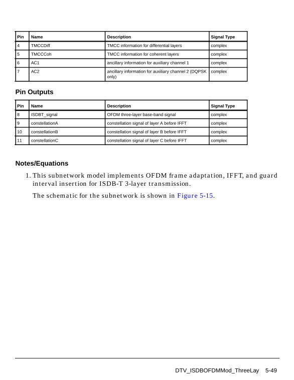
Pin Outputs
Notes/Equations
1. This subnetwork model implements OFDM frame adaptation, IFFT, and guardinterval insertion for ISDB-T 3-layer transmission.
The schematic for the subnetwork is shown in Figure 5-15.
4 TMCCDiff TMCC information for differential layers complex
5 TMCCCoh TMCC information for coherent layers complex
6 AC1 ancillary information for auxiliary channel 1 complex
7 AC2 ancillary information for auxiliary channel 2 (DQPSKonly)
complex
Pin Name Description Signal Type
8 ISDBT_signal OFDM three-layer base-band signal complex
9 constellationA constellation signal of layer A before IFFT complex
10 constellationB constellation signal of layer B before IFFT complex
11 constellationC constellation signal of layer C before IFFT complex
Pin Name Description Signal Type
DTV_ISDBOFDMMod_ThreeLay 5-49

ISDB-T Components
Figure 5-15. DTV_ISDBOFDMMod_ThreeLay Schematic
2. Parameter Details
SegmentsA is set to 1 permanently.
SegmentsA+SegmentsB+SegmentsC=13 is required.
SegmentsB and SegmentsC cannot be 0.
GuardInterval value is 1/32, 1/16, 1/8 or 1/4 (the ratio of guard interval lengthto useful symbol length).
OversamplingOption is Ratio 1, Ratio 2, ... , Ratio 32, which indicates the ratioof the output sampling frequency to the basic sampling frequency is 1, 2, ... , 32.
3. Each firing, one OFDM symbol with guard interval is generated. The number ofdata, TMCC, AC1, and AC2 particles consumed in one OFDM symbol are listedin Table 5-9.
5-50 DTV_ISDBOFDMMod_ThreeLay
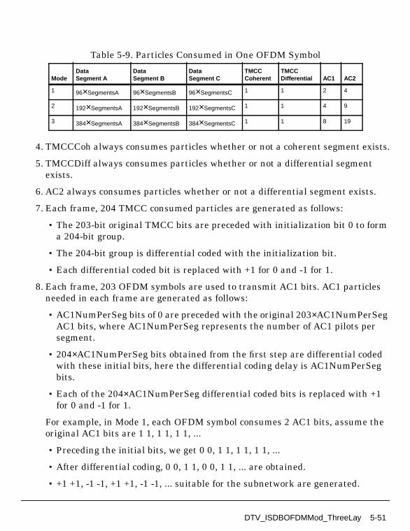
4. TMCCCoh always consumes particles whether or not a coherent segment exists.
5. TMCCDiff always consumes particles whether or not a differential segmentexists.
6. AC2 always consumes particles whether or not a differential segment exists.
7. Each frame, 204 TMCC consumed particles are generated as follows:
• The 203-bit original TMCC bits are preceded with initialization bit 0 to forma 204-bit group.
• The 204-bit group is differential coded with the initialization bit.
• Each differential coded bit is replaced with +1 for 0 and -1 for 1.
8. Each frame, 203 OFDM symbols are used to transmit AC1 bits. AC1 particlesneeded in each frame are generated as follows:
• AC1NumPerSeg bits of 0 are preceded with the original 203×AC1NumPerSegAC1 bits, where AC1NumPerSeg represents the number of AC1 pilots persegment.
• 204×AC1NumPerSeg bits obtained from the first step are differential codedwith these initial bits, here the differential coding delay is AC1NumPerSegbits.
• Each of the 204×AC1NumPerSeg differential coded bits is replaced with +1for 0 and -1 for 1.
For example, in Mode 1, each OFDM symbol consumes 2 AC1 bits, assume theoriginal AC1 bits are 1 1, 1 1, 1 1, ...
• Preceding the initial bits, we get 0 0, 1 1, 1 1, 1 1, ...
• After differential coding, 0 0, 1 1, 0 0, 1 1, ... are obtained.
• +1 +1, -1 -1, +1 +1, -1 -1, ... suitable for the subnetwork are generated.
Table 5-9. Particles Consumed in One OFDM Symbol
ModeDataSegment A
DataSegment B
DataSegment C
TMCCCoherent
TMCCDifferential AC1 AC2
1 96×SegmentsA 96×SegmentsB 96×SegmentsC 1 1 2 4
2 192×SegmentsA 192×SegmentsB 192×SegmentsC 1 1 4 9
3 384×SegmentsA 384×SegmentsB 384×SegmentsC 1 1 8 19
DTV_ISDBOFDMMod_ThreeLay 5-51

ISDB-T Components
9. While AC2 is similar to AC1, it is used for differential segments only.
References
[1]ARIB STD-B31 Version 1.5, Transmission System for Digital TerrestrialTelevision Broadcasting, July 29, 2003.
5-52 DTV_ISDBOFDMMod_ThreeLay

DTV_ISDBOFDMMod_TwoLay
Description Two-layer OFDM modulation of ISDB-TLibrary DTV, ISDB-T
Parameters
Pin Inputs
Name Description Default Type Range
Mode transmission mode: Mode1, Mode 2, Mode 3
Mode 1 enum
MappingModeA signal constellations andmapping of layer A: ADQPSK, A QPSK, AQAM-16, A QAM-64
A DQPSK enum
SegmentsA segment number of layer A 5 int [1, 13]
MappingModeB signal constellations andmapping of layer B: BDQPSK, B QPSK, BQAM-16, B QAM-64
B QAM-64 enum
SegmentsB segment number of layer B 8 int [1, 13]
GuardInterval guard interval (fractionalFFT size)
1/32 real [0, 1]
OversamplingOption oversampling ratio option:Ratio 1, Ratio 2, Ratio 4,Ratio 8, Ratio 16, Ratio 32
Ratio 1 enum
Pin Name Description Signal Type
1 DataA input data of layer A complex
2 DataB input data of layer B complex
3 TMCCDiff TMCC information for differential layers complex
4 TMCCCoh TMCC information for coherent layers complex
5 AC1 ancillary information for auxiliary channel 1 complex
6 AC2 ancillary information for auxiliary channel 2 (DQPSKonly)
complex
DTV_ISDBOFDMMod_TwoLay 5-53

ISDB-T Components
Pin Outputs
Notes/Equations
1. This subnetwork model implements OFDM segment adaptation, IFFT, andguard interval insertion for ISDB-T 2-layer transmission.
The schematic for this subnetwork is shown in Figure 5-16.
Figure 5-16. DTV_ISDBOFDMMod_TwoLay Schematic
2. Parameter Details
SegmentsA+SegmentsB=13 is required.
SegmentsB cannot be 0.
GuardInterval value is 1/32, 1/16, 1/8 or 1/4 (the ratio of guard interval lengthto useful symbol length).
Pin Name Description Signal Type
7 ISDBT_signal ISDB-T two-layer base-band signal complex
8 constellationA constellation signal of layer A before IFFT complex
9 constellationB constellation signal of layer B before IFFT complex
5-54 DTV_ISDBOFDMMod_TwoLay

OversamplingOption is Ratio 1, Ratio 2, ... , Ratio 32, which indicates the ratioof the output sampling frequency to the basic sampling frequency is 1, 2, ... , 32.
3. Each firing, the subnetwork generates one OFDM symbol with guard interval.The number of data, TMCC, AC1, and AC2 particles consumed in one OFDMsymbol are listed in Table 5-10.
4. TMCCCoh always consumes particles whether or not a coherent segment exists.
5. TMCCDiff always consumes particles whether or not a differential segmentexists.
6. AC2 always consumes particles whether or not a differential segment exists.
7. Each frame, 204 TMCC consumed particles are generated as follows:
• The original 203 TMCC bits are preceded with initialization bit 0 to form a204-bit group.
• The 204-bit group is differential coded with the initialization bit.
• Each of the differential coded bits are replaced with +1 for 0 and -1 for 1.
8. Each frame, 203 OFDM symbols are used to transmit AC1 bits. AC1 particlesneeded in each frame are generated as follows:
• AC1NumPerSeg bits of 0 are preceded with the original 203×AC1NumPerSegAC1 bits, where AC1NumPerSeg represents the number of AC1 pilots persegment.
• 204×AC1NumPerSeg bits obtained in the first step are differential codedwith these initial bits; here the differential coding delay is AC1NumPerSegbits.
• Each of the 204×AC1NumPerSeg differential coded bits are replaced with +1for 0 and -1 for 1.
Table 5-10. Particles Consumed in One OFDM Symbol
ModeDataSegment A
DataSegment B
TMCCCoherent
TMCCDifferential AC1 AC2
1 96×SegmentsA 96×SegmentsB 1 1 2 4
2 192×SegmentsA 192×SegmentsB 1 1 4 9
3 384×SegmentsA 384×SegmentsB 1 1 8 19
DTV_ISDBOFDMMod_TwoLay 5-55

ISDB-T Components
For example, in Mode 1, each OFDM symbol consumes 2 AC1 bits, assume theoriginal AC1 bits are 1 1, 1 1, 1 1, ...
• Preceding initial bits, we get 0 0, 1 1, 1 1, 1 1, ...
• After differential coding, 0 0, 1 1, 0 0, 1 1, ... are obtained.
• +1 +1, -1 -1, +1 +1, -1 -1, ... suitable for the subnetwork are then generated.
9. While AC2 is similar to AC1, it is used for differential segments only.
References
[1]ARIB STD-B31 Version 1.5, Transmission System for Digital TerrestrialTelevision Broadcasting, July 29, 2003.
5-56 DTV_ISDBOFDMMod_TwoLay

DTV_LFSRCoder
Description LFSR cyclic coderLibrary DTV, ISDB-TClass SDFDTV_LFSRCoder
Parameters
Pin Inputs
Pin Outputs
Notes/Equations
1. This model performs cyclic coding over the input signal.
2. Cyclic codes are linear block codes with an important additional property: acyclic, or end-around, shift of any codeword is also a codeword. Algebraically,the codewords constitute a group under the cyclic shift operation.
Name Description Default Type Range
Code length of code bits 184 int (0, ∞)
Info length of information bits 102 int (0, ∞)
Polynomial generation polynomial’ssuffix(X^P[0]+X^P[1]+...X^P[m])
0 4 10 18 22 2434 36 40 48 52 5666 67 71 76 77 82
int array [0, ∞)
Pin Name Description Signal Type
1 input signal to be encoded int
Pin Name Description Signal Type
2 output error protected signal int
DTV_LFSRCoder 5-57

ISDB-T Components
If C=(c0, c1, ... , cn-1) denotes a codeword with elements in GF(q), we associatewith it a polynomial over GF(q) of degree at most n−1:
Note the coefficients of the polynomial are in GF(q). Now consider aone-position right cyclic shift of C, producing
.
The associated polynomial would be
which is another polynomial of degree at most n-1.
Polynomials c(x) and c(1)(x) are related by
Now suppose that we are given a particular cyclic (n,k) code over GF(q). Wedefine the generator polynomial g(x) of the cyclic code as the mnemonicpolynomial of minimum degree among the set of nonzero codeword polynomials.We assume that the degree of this polynomial is r ≤ n-1and write
where again the coefficients are members of GF(q).
Two fundamental properties of cyclic codes are:
• Property 1. c(x) is a code polynomial if c(x)=u(x)g(x), where u(x) is of degreen-1-r or less.
• Property 2. g(x) generates an (n,k) cyclic code if g(x) is of degree n-k and is afactor of xn -1 .
Property 1 of cyclic codes suggests one implementation of an encoder:performing the computation of c(x)=u(x)g(x). Such an encoding system is shownin Figure 5-17 and is nothing more than a digital transversal filter over GF(q)that convolves the information sequence uk-1, ... , u0 with the impulse responsegn-k, gn-k-1, ... , g0.
c x( ) c0 c1x c2x2 … cn 1– xn 1–+ + + +=
C 1( ) cn 1– c0 … cn 2–, , ,( )=
c 1( ) x( ) cn 1– c0x c1x2 … cn 2– xn 1–+ + + +=
c 1( ) x( ) xc x( )mod xn1–( )=
g x( ) g0 g1x g2x2 … gn 1– xn 1–+ + + +=
5-58 DTV_LFSRCoder

Figure 5-17. Non-Systematic Encoder for Cyclic Code
References
[1]ARIB-JAPAN, Terrestrial Integrated Services Digital Broadcasting (ISDB-T);Specification of Channel Coding, Framing Structure and Modulation,Sept.1998.
[2]W. Xinmei and X. Guozhen, Error Correcting Codes: Theory and Application,Xidian University Press, P.R.China, 1991.
gn-k gn-k-1 gn-k-2 g1x x x x
++ ++
...
g0x
u0,u1,...,uk-1
c0,c1,...,cn-1
DTV_LFSRCoder 5-59
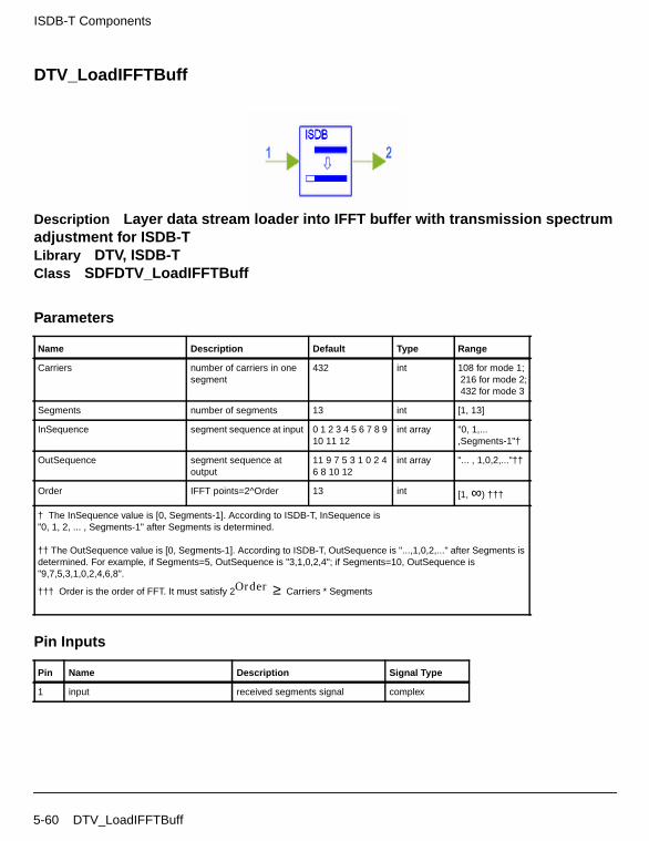
ISDB-T Components
DTV_LoadIFFTBuff
Description Layer data stream loader into IFFT buffer with transmission spectrumadjustment for ISDB-TLibrary DTV, ISDB-TClass SDFDTV_LoadIFFTBuff
Parameters
Pin Inputs
Name Description Default Type Range
Carriers number of carriers in onesegment
432 int 108 for mode 1; 216 for mode 2; 432 for mode 3
Segments number of segments 13 int [1, 13]
InSequence segment sequence at input 0 1 2 3 4 5 6 7 8 910 11 12
int array "0, 1,...,Segments-1"†
OutSequence segment sequence atoutput
11 9 7 5 3 1 0 2 46 8 10 12
int array "... , 1,0,2,..."††
Order IFFT points=2^Order 13 int [1, ∞) †††
† The InSequence value is [0, Segments-1]. According to ISDB-T, InSequence is"0, 1, 2, ... , Segments-1" after Segments is determined.
†† The OutSequence value is [0, Segments-1]. According to ISDB-T, OutSequence is "...,1,0,2,..." after Segments isdetermined. For example, if Segments=5, OutSequence is "3,1,0,2,4"; if Segments=10, OutSequence is"9,7,5,3,1,0,2,4,6,8".
††† Order is the order of FFT. It must satisfy 2Order ≥ Carriers * Segments
Pin Name Description Signal Type
1 input received segments signal complex
5-60 DTV_LoadIFFTBuff

Pin Outputs
Notes/Equations
1. This model loads the adjusted data segments into the IFFT buffer withtransmission spectrum adjustment for ISDB-T.
2. The input data segment order is adjusted in order to change its transmissionspectrum. The input segment is changed into the output segment; the changedsegments are placed in the IFFT buffer by zero padded in the center of thebuffer.
Assume x(0), x(1), ... , x(N-1) are the signal of the changed segments, where
N = Length × Segments + 1M = 2FFTStage
y(0), y(1), ... , y(M-1)
are the outputs of the model. Data loading is performed as follows:
References
[1]ARIB-JAPAN, Terrestrial Integrated Services Digital Broadcasting (ISDB-T);Specification of Channel Coding, Framing Structure and Modulation,Sept.1998.
Pin Name Description Signal Type
2 output IFFT input signal with spectrum change and zeropadded
complex
y i( ) x N2----- i+
= i 0 … N 1+2
-------------- 1–, ,=
y i( ) 0= i N 1+2
-------------- … M N2-----– 1–, ,=
y i( ) x i M– N2-----+
= i M N2----- … M, ,–=
DTV_LoadIFFTBuff 5-61

ISDB-T Components
DTV_ISDBModulation
Description ISDB-T TSP modulationLibrary DTV, ISDB-T
Parameters
Pin Inputs
Pin Outputs
Notes/Equations
1. This subnetwork model performs bit-wise interleaving and data mapping.
The schematic for this subnetwork is shown in Figure 5-18.
Name Description Default Type Range
Mode transmission mode: Mode1, Mode 2, Mode 3
Mode 1 enum
MappingMode signal constellations andmapping: DQPSK, QPSK,QAM-16, QAM-64
DQPSK enum
Segments number of segments perlayer
13 int [1, 13]
Pin Name Description Signal Type
1 In input int
Pin Name Description Signal Type
2 Out output complex
5-62 DTV_ISDBModulation

Figure 5-18. DTV_ISDBModulation Schematic
2. DTV_Delay adds delay according to Table 5-11. Bit interleaving causes a delayof 120 complex data (I+jQ). Total transmitter and receiver delay is adjustedbased on two OFDM symbols.
3. Bit interleaving and mapping for the four modulation types are shown inFigure 5-19 through Figure 5-22.
Table 5-11. Bit Interleaving Delay Adjustment
Modulation
Number of bits for Delay Adjustment
Mode 1 Mode 2 Mode 3
DQPSKQPSK
384×N-240 768×N-240 1536×N-240
16QAM 768×N-480 1536×N-480 3072×N-480
64QAM 1152×N-720 2304×N-720 4608×N-720
where N = number of segments used in a certain layer
DTV_ISDBModulation 5-63

ISDB-T Components
Figure 5-19. DQPSK Modulation
Figure 5-20. QPSK Modulation
Figure 5-21. 16QAM Modulation
Figure 5-22. 64QAM Modulation
References
[1]ARIB STD-B31 Version 1.5, Transmission System for Digital TerrestrialTelevision Broadcasting, July 29, 2003.
S/P120-bit Delay
PhaseCalculator
PhaseShifter
Delay
b0
b1b0, b1, ...
b0′
b1′
I
Q
I j
Qj
I j-1
Q j-1
θk
S/P120-bit Delay
QPSKMapping
b0
b1b0, b1, ...
I
Q
S/P
40-bit Delay16 QAMMapping
b0
b1b0, b1, b2, b3 ...I
Q80-bit Delay
120-bit Delay
b2
b3
S/P
24-bit Delay
64 QAMMapping
b0
b1
b0, b1, b2, b3, b4, b5...
I
Q
48-bit Delay
72-bit Delay
b2
b3
96-bit Delayb4
120-bit Delayb5
5-64 DTV_ISDBModulation

DTV_MuxCohSegs
Description ISDB-T multiplex coherent segmentsLibrary DTV, ISDB-TClass SDFDTV_MuxCohSegs
Parameters
Pin Inputs
Name Description Default Type Range
Carriers number of carriers in onesegment
432 int 108 for mode 1; 216 for mode 2; 432 for mode 3
Segments number of segments 1 int [1, 13]
Start_Seg initial number of segment(0 to Segments-1)
0 int [0, 12]
SPnumber number of scattered pilotsin each segment
36 int [0, ∞)†
SPperiod distance in carriersbetween nearby scatteredpilots
12 int (0, ∞)††
SPstart start position of scatteredpilots in carriers
0 int [0, ∞)††
SPoffset offset value of SPstart ineach symbol
3 int [0, ∞)††
SPphase initial phase of scatteredpilots
0 int [0,SPperiod/SPoffset-1]
† SPnumber = 9 for mode 1, 18 for mode 2, 36 for mode 3, per segment in ISDB-T systems.
†† SPperiod = 12, SPstart = 0, SPoffset = 3 in ISDB-T systems.
Pin Name Description Signal Type
1 data TSP data iuput complex
DTV_MuxCohSegs 5-65

ISDB-T Components
Pin Outputs
Notes/Equations
1. This model multiplexes TSP (transport stream packet) data, TMCC(transmission and multiplexing configuration control) data, and AC (auxiliarychannel) data into the coherent modulation OFDM segments (such as QPSK,16-QAM, and 64-QAM modulation) according to Figure 5-23 and Table 5-12.
2. IntState of Carriers determines the number of TMCC and AC in each segment.Then, IntState of Start_Seg and Segments determines the TMCC and ACpositions in each corresponding segment according to Table 5-12.
The PRBS sequences in each segment are generated according to Figure 5-24and the initial sets of PRBS register in Table 5-13. The PRBS in initialized sothat the first output bit from the PRBS coincides with the first active carrier. Anew value is generated by the PRBS on every used carriers in each segment(whether or not it is a pilot).
Positions of corresponding scattered pilots are generated as follows. For symbolof index l (ranging from 0 to 203), carriers for which index k belongs to subset
are scattered pilots positions. Scattered pilots positions are controlled by
• SPnumber, which determines the number of scattered pilots in each segment,is: 9 in mode 1 (Length=108), 18 in mode 2 (Length=216), or 36 in mode 3(Length=432).
• SPperiod=12, SPstart=0, SPoffset=3 in all three modes according to ISDB-T.
After determining TMCC, AC, and SP positions in each corresponding segmentand the value of the PRBS sequence in all active carriers in each segment,TMCC, AC, and TSP data are multiplexed into the coherent segments.
2 TMCC TMCC data input complex
3 AC AC data input complex
Pin Name Description Signal Type
4 output coherent segments data complex
Pin Name Description Signal Type
k 3 l mod 4× 12p+= p integer p 0 k 0 Length Segments×[ , ]∈,≥,
5-66 DTV_MuxCohSegs

According to the TMCC position and the PRBS sequence, one TMCC bit isoutput in every TMCC position.
where NTMCC is the number of TMCCs in one segment; PilotValue is the PRBSsequence in the corresponding segment; x[i] is segment data.
AC data is:
Except for AC, TMCC, and SP positions, the remaining positions in one segmentare TSP data positions.
x TMCCposition l[ ][ ] PilotValue TMCCposition l[ ][ ] TMCC×=
x ACposition i[ ][ ] PilotValue ACposition i[ ][ ] AC i[ ]×=
x i[ ] data i[ ]=
DTV_MuxCohSegs 5-67
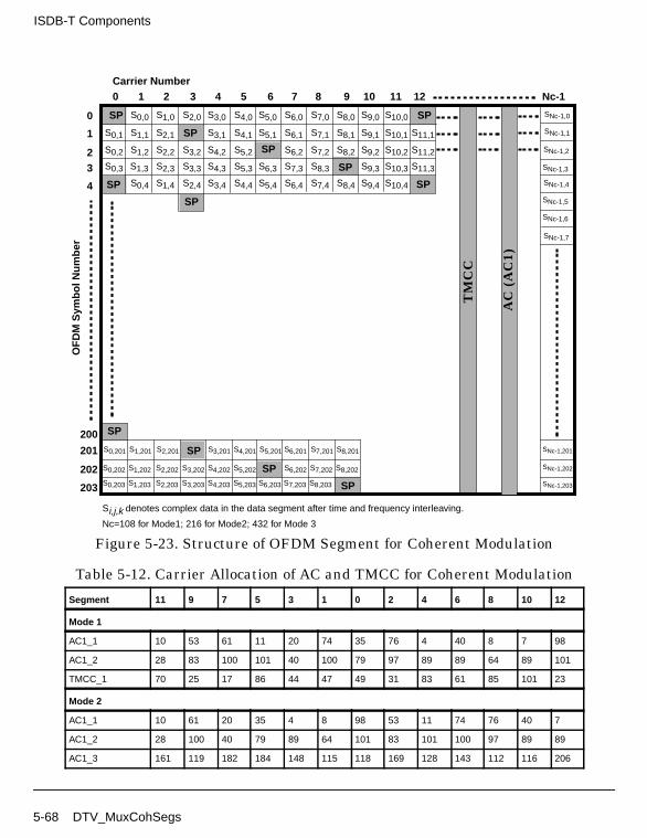
ISDB-T Components
Figure 5-23. Structure of OFDM Segment for Coherent Modulation
Table 5-12. Carrier Allocation of AC and TMCC for Coherent Modulation
Segment 11 9 7 5 3 1 0 2 4 6 8 10 12
Mode 1
AC1_1 10 53 61 11 20 74 35 76 4 40 8 7 98
AC1_2 28 83 100 101 40 100 79 97 89 89 64 89 101
TMCC_1 70 25 17 86 44 47 49 31 83 61 85 101 23
Mode 2
AC1_1 10 61 20 35 4 8 98 53 11 74 76 40 7
AC1_2 28 100 40 79 89 64 101 83 101 100 97 89 89
AC1_3 161 119 182 184 148 115 118 169 128 143 112 116 206
TM
CC
AC
(A
C1)
0 1 2 3 4 5 6 7 8 9 10 11 12 Nc-1Carrier Number
OF
DM
Sym
bol N
umbe
r
0
1
23
4
203
202
201
200
SP
SP
SP
SP
SP
SP
SP
SP
SP
SP
SP
SP
S0,0 S1,0 S2,0 S3,0 S4,0 S5,0 S6,0 S7,0 S8,0 S9,0 S10,0
S0,1 S1,1 S2,1
S0,2 S1,2 S2,2
S0,3 S1,3 S2,3
S0,4 S1,4 S2,4
S3,1 S4,1 S5,1 S6,1 S7,1 S8,1 S9,1 S10,1 S11,1
S3,2 S4,2 S5,2
S3,3 S4,3 S5,3
S3,4 S4,4 S5,4
S6,3 S7,3 S8,3
S6,4 S7,4 S8,4
S6,2 S7,2 S8,2 S9,2 S10,2 S11,2
S9,3 S10,3 S11,3
S9,4 S10,4
S0,201 S1,201 S2,201 S3,201 S4,201 S5,201 S7,201S6,201 S8,201
S0,202 S1,202 S2,202 S3,202 S4,202 S5,202 S7,202S6,202 S8,202
S0,203 S1,203 S2,203 S3,203 S4,203 S5,203 S6,203 S7,203 S8,203
SNc-1,0
SNc-1,1
SNc-1,2
SNc-1,3
SNc-1,4
SNc-1,5
SNc-1,6
SNc-1,7
SNc-1,201
SNc-1,202
SNc-1,203
Si,j,k denotes complex data in the data segment after time and frequency interleaving.
Nc=108 for Mode1; 216 for Mode2; 432 for Mode 3
5-68 DTV_MuxCohSegs

Figure 5-24. Generation of PRBS Sequence
AC1_4 191 209 208 205 197 197 136 208 148 187 197 172 209
TMCC_1 70 17 44 49 83 85 23 25 86 47 31 61 101
TMCC_2 133 194 155 139 169 209 178 125 152 157 191 193 131
Mode 3
AC1_1 10 20 4 98 11 76 7 61 35 8 53 74 40
AC1_2 28 40 89 101 101 97 89 100 79 64 83 100 89
AC1_3 161 182 148 118 128 112 206 119 184 115 169 143 116
AC1_4 191 208 197 136 148 197 209 209 205 197 208 187 172
AC1_5 277 251 224 269 290 256 226 236 220 314 227 292 223
AC1_6 316 295 280 299 316 305 244 256 305 317 317 313 305
AC1_7 335 400 331 385 359 332 377 398 364 334 344 328 422
AC1_8 425 421 413 424 403 388 407 424 413 352 364 413 425
TMCC_1 70 44 83 23 86 31 101 17 49 85 25 47 61
TMCC_2 131 155 169 178 152 191 131 194 139 209 125 157 193
TMCC_3 233 265 301 241 263 277 286 260 299 239 302 247 317
TMCC_4 410 355 425 341 373 409 349 371 385 394 368 407 347
Table 5-12. Carrier Allocation of AC and TMCC for Coherent Modulation (continued)
D D D D D D D D
0 1 2 3 4 5 6 7
D D D
8 9 10
+
Degree:
g(x) = x17 + x9 + I
Output = Wi
DTV_MuxCohSegs 5-69

ISDB-T Components
References
[1]ARIB-JAPAN, Terrestrial Integrated Services Digital Broadcasting (ISDB-T);Specification of Channel Coding, Framing Structure and Modulation,Sept.1998.
Table 5-13. Initial Sets of PRBS Register
SegmentNumber Initial Sets for Mode 1 † Initial Sets for Mode 2 † Initial Sets for Mode 3 †
11 1 1 1 1 1 1 1 1 1 1 1 1 1 1 1 1 1 1 1 1 1 1 1 1 1 1 1 1 1 1 1 1 1
9 1 1 0 1 1 0 0 1 1 1 1 0 1 1 0 1 0 1 1 1 1 0 1 1 0 1 1 1 0 0 1 0 1
7 0 1 1 0 1 0 1 1 1 1 0 1 1 0 1 1 1 0 0 1 0 1 1 0 0 1 0 1 0 0 0 0 0
5 0 1 0 0 0 1 0 1 1 1 0 1 1 0 0 1 0 0 0 0 1 0 0 1 1 1 0 0 0 1 0 0 1
3 1 1 0 1 1 1 0 0 1 0 1 1 0 0 1 0 1 0 0 0 0 0 0 0 1 0 0 0 1 1 0 0 1
1 0 0 1 0 1 1 1 1 0 1 0 0 0 0 0 1 0 1 1 0 0 0 1 1 1 0 0 1 1 0 1 1 0
0 1 1 0 0 1 0 0 0 0 1 0 0 1 1 1 0 0 0 1 0 0 1 0 0 1 0 0 0 0 1 0 1 1
2 0 0 0 1 0 0 0 0 1 0 0 0 0 0 0 0 1 0 0 1 0 0 1 1 1 0 0 1 1 1 1 0 1
4 1 0 0 1 0 1 0 0 0 0 0 0 0 1 0 0 0 1 1 0 0 1 0 1 1 0 1 0 1 0 0 1 1
6 1 1 1 1 0 1 1 0 0 0 0 0 1 1 0 0 1 1 1 0 0 1 1 0 1 1 1 0 1 0 0 1 0
8 0 0 0 0 1 0 1 1 0 0 0 1 1 1 0 0 1 1 0 1 1 0 0 1 1 0 0 0 1 0 0 1 0
10 1 0 1 0 0 1 0 0 1 1 1 0 0 1 0 1 0 1 0 0 0 1 1 1 1 1 0 1 0 0 1 0 1
12 0 1 1 1 0 0 0 1 0 0 1 0 0 1 0 0 0 0 1 0 1 1 0 0 0 1 0 0 1 1 1 0 0
†Degree from 0 to 10 in Figure 5-24.
5-70 DTV_MuxCohSegs

DTV_MuxDiffSegs
Description ISDB-T multiplex differential segmentsLibrary DTV, ISDB-TClass SDFDTV_MuxDiffSegs
Parameters
Pin Inputs
Pin Outputs
Notes/Equations
1. This model multiplexes TSP (transport stream packet), TMCC (transmissionand multiplexing configuration control), AC1 (auxiliary channel 1), and AC2
Name Description Default Type Range
Carriers number of carriers in onesegment
432 int 108 for mode 1; 216 for mode 2; 432 for mode 3
Segments number of segments 1 int [1, 13]
Start_Seg initial number of segment(0 to Segments-1)
0 int [0, 12]
Pin Name Description Signal Type
1 data TSP data input complex
2 TMCC TMCC data input complex
3 AC1 AC1 data input complex
4 AC2 AC2 data input complex
Pin Name Description Signal Type
5 output differential segments data output complex
DTV_MuxDiffSegs 5-71

ISDB-T Components
(auxiliary channel 2) data into the differential modulation OFDM segmentsaccording to Figure 5-25 and Table 5-14.
2. IntState of Length determines the number of TMCC, AC1, and AC2 in eachsegment. IntState of Start_Seg and Segments determine the TMCC, AC1, andAC2 positions in each corresponding segment according to Table 5-14.
The PRBS sequences in each segment are generated according to Figure 5-26and the initial sets of PRBS register in Table 5-15. The PRBS in initialized sothat the first output bit from the PRBS coincides with the first active carrier. Anew value is generated by the PRBS on every carrier used in each segment(whether or not it is a pilot).
After determining all TMCC, AC1, and AC2 positions in each correspondingsegment and the value of the PRBS sequence in all the active carriers in eachsegment, TMCC, AC1, AC2, and TSP data are multiplexed into differentialsegments.
where NTMCC is the number of TMCC in one segment; PilotValue is the PRBSsequence in corresponding segment; x[i] is the output segment data.
The output of the input AC1 data is:
AC2 data is:
Except for the AC1, AC2, and TMCC data positions, the remaining positions inone segment are the TSP data positions.
x[i] = data[i]
x TMCCposition l[ ][ ] PilotValue TMCCposition l[ ][ ] TMCC×=
x AC1position i[ ][ ] PilotValue AC1position i[ ][ ] AC1 i[ ]×=
x AC2position i[ ][ ] PilotValue AC2position i[ ][ ] AC2 i[ ]×=
5-72 DTV_MuxDiffSegs

Figure 5-25. Structure of OFDM Segment for Differential Modulation
Table 5-14. Carrier Allocation of CP, AC, and TMCC forDifferential Modulation
Segment 11 9 7 5 3 1 0 2 4 6 8 10 12
Mode 1
CP 0 0 0 0 0 0 0 0 0 0 0 0 0
AC1_1 10 53 61 11 20 74 35 76 4 40 8 7 98
AC1_2 28 83 100 101 40 100 79 97 89 89 64 89 101
AC2_1 3 3 29 28 23 30 3 5 13 72 36 25 10
AC2_2 45 15 41 45 63 81 72 18 93 95 48 30 30
AC2_3 59 40 84 81 85 92 85 57 98 100 52 42 55
AC2_4 77 58 93 91 105 103 89 92 102 105 74 104 81
S1,0
S1,1
S1,2
S1,3
S1,4
S1,5
S1,6
S1,7
S1,203
CP
TM
CC
AC
(A
C1,
AC
2)
0 1 2 Nc-1Carrier Number
OF
DM
Sym
bol N
umbe
r
0
1
23
4
203
SNc-1,0
SNc-1,1
SNc-1,2
SNc-1,3
SNc-1,4
SNc-1,5
SNc-1,6
SNc-1,7
SNc-1,203
Si,j,k denotes complex data in the data segment after time and frequency interleaving.
Nc=108 for Mode1; 216 for Mode2; 432 for Mode 3
567
S0,0
S0,1
S0,2
S0,3
S0,4
S0,5
S0,6
S0,7
S0,203
DTV_MuxDiffSegs 5-73

ISDB-T Components
TMCC_1 13 25 4 36 10 7 49 31 16 5 78 34 23
TMCC_2 50 63 7 48 28 25 61 39 30 10 82 48 37
TMCC_3 70 73 17 55 44 47 96 47 37 21 85 54 51
TMCC_4 83 80 51 59 47 60 99 65 74 44 98 70 68
TMCC_5 87 93 71 86 54 87 104 72 83 61 102 101 105
Mode 2
CP 0 0 0 0 0 0 0 0 0 0 0 0 0
AC1_1 10 61 20 35 4 8 98 53 11 74 76 40 7
AC1_2 28 100 40 79 89 64 101 83 101 100 97 89 89
AC1_3 161 119 182 184 148 115 118 169 128 143 112 116 206
AC1_4 191 209 208 205 197 197 136 208 148 187 197 172 209
AC2_1 3 29 23 3 13 36 10 3 28 30 5 72 25
AC2_2 45 41 63 72 93 48 30 15 45 81 18 95 30
AC2_3 59 84 85 85 98 52 55 40 81 92 57 100 42
AC2_4 77 93 105 89 102 74 81 58 91 103 92 105 104
AC2_5 108 108 108 108 108 108 108 108 108 108 108 108 108
AC2_6 111 136 138 113 180 133 111 137 131 111 121 144 118
AC2_7 123 153 189 126 203 138 153 149 171 180 201 156 138
AC2_8 148 189 200 165 208 150 167 192 193 193 206 160 163
AC2_9 166 199 211 200 213 212 185 201 213 197 210 182 189
TMCC_1 13 4 10 49 16 78 23 25 36 7 31 5 34
TMCC_2 50 7 28 61 30 82 37 63 48 25 39 10 48
TMCC_3 70 17 44 96 37 85 51 73 55 47 47 21 54
TMCC_4 83 51 47 99 74 98 68 80 59 60 65 44 70
TMCC_5 87 71 54 104 83 102 105 93 86 87 72 61 101
TMCC_6 133 144 115 139 113 142 121 112 118 157 124 186 131
TMCC_7 171 156 133 147 118 156 158 115 136 169 138 190 145
TMCC_8 181 163 155 155 129 162 178 125 152 204 145 193 159
TMCC_9 188 167 168 173 152 178 191 159 155 207 182 206 176
TMCC_10 201 194 195 180 169 209 195 179 162 212 191 210 213
Mode 3
CP 0 0 0 0 0 0 0 0 0 0 0 0 0
AC1_1 10 20 4 98 11 76 7 61 35 8 53 74 40
AC1_2 28 40 89 101 101 97 89 100 79 64 83 100 89
Table 5-14. Carrier Allocation of CP, AC, and TMCC forDifferential Modulation (continued)
Segment 11 9 7 5 3 1 0 2 4 6 8 10 12
5-74 DTV_MuxDiffSegs
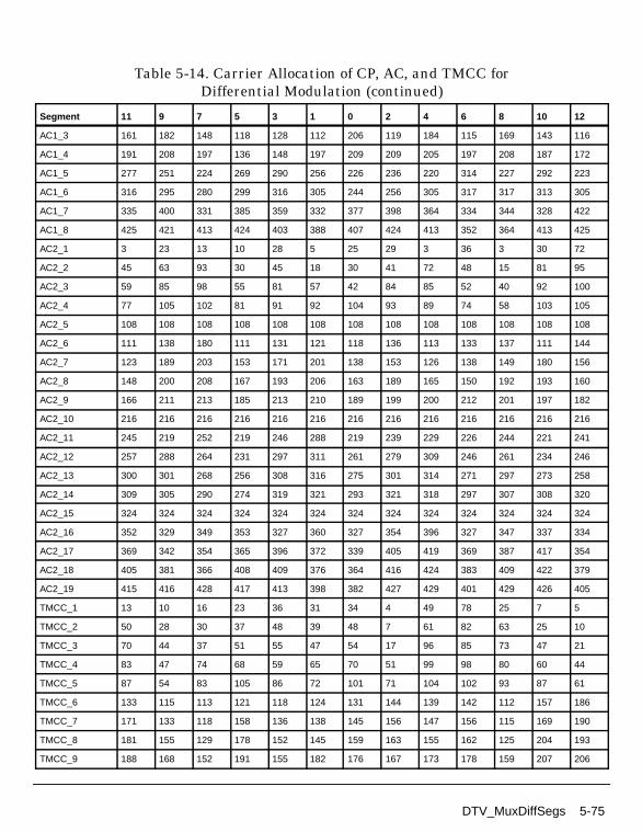
AC1_3 161 182 148 118 128 112 206 119 184 115 169 143 116
AC1_4 191 208 197 136 148 197 209 209 205 197 208 187 172
AC1_5 277 251 224 269 290 256 226 236 220 314 227 292 223
AC1_6 316 295 280 299 316 305 244 256 305 317 317 313 305
AC1_7 335 400 331 385 359 332 377 398 364 334 344 328 422
AC1_8 425 421 413 424 403 388 407 424 413 352 364 413 425
AC2_1 3 23 13 10 28 5 25 29 3 36 3 30 72
AC2_2 45 63 93 30 45 18 30 41 72 48 15 81 95
AC2_3 59 85 98 55 81 57 42 84 85 52 40 92 100
AC2_4 77 105 102 81 91 92 104 93 89 74 58 103 105
AC2_5 108 108 108 108 108 108 108 108 108 108 108 108 108
AC2_6 111 138 180 111 131 121 118 136 113 133 137 111 144
AC2_7 123 189 203 153 171 201 138 153 126 138 149 180 156
AC2_8 148 200 208 167 193 206 163 189 165 150 192 193 160
AC2_9 166 211 213 185 213 210 189 199 200 212 201 197 182
AC2_10 216 216 216 216 216 216 216 216 216 216 216 216 216
AC2_11 245 219 252 219 246 288 219 239 229 226 244 221 241
AC2_12 257 288 264 231 297 311 261 279 309 246 261 234 246
AC2_13 300 301 268 256 308 316 275 301 314 271 297 273 258
AC2_14 309 305 290 274 319 321 293 321 318 297 307 308 320
AC2_15 324 324 324 324 324 324 324 324 324 324 324 324 324
AC2_16 352 329 349 353 327 360 327 354 396 327 347 337 334
AC2_17 369 342 354 365 396 372 339 405 419 369 387 417 354
AC2_18 405 381 366 408 409 376 364 416 424 383 409 422 379
AC2_19 415 416 428 417 413 398 382 427 429 401 429 426 405
TMCC_1 13 10 16 23 36 31 34 4 49 78 25 7 5
TMCC_2 50 28 30 37 48 39 48 7 61 82 63 25 10
TMCC_3 70 44 37 51 55 47 54 17 96 85 73 47 21
TMCC_4 83 47 74 68 59 65 70 51 99 98 80 60 44
TMCC_5 87 54 83 105 86 72 101 71 104 102 93 87 61
TMCC_6 133 115 113 121 118 124 131 144 139 142 112 157 186
TMCC_7 171 133 118 158 136 138 145 156 147 156 115 169 190
TMCC_8 181 155 129 178 152 145 159 163 155 162 125 204 193
TMCC_9 188 168 152 191 155 182 176 167 173 178 159 207 206
Table 5-14. Carrier Allocation of CP, AC, and TMCC forDifferential Modulation (continued)
Segment 11 9 7 5 3 1 0 2 4 6 8 10 12
DTV_MuxDiffSegs 5-75

ISDB-T Components
Figure 5-26. Generation of PRBS Sequence
TMCC_10 201 195 169 195 162 191 213 194 180 209 179 212 210
TMCC_11 220 265 294 241 223 221 229 226 232 239 252 247 250
TMCC_12 223 277 298 279 241 226 266 244 246 253 264 255 264
TMCC_13 233 312 301 289 263 237 286 260 253 267 271 263 270
TMCC_14 267 315 314 296 276 260 299 263 290 284 275 281 286
TMCC_15 287 320 318 309 303 277 303 270 299 321 302 288 317
TMCC_16 360 355 358 328 373 402 349 331 329 337 334 340 347
TMCC_17 372 363 372 331 385 406 387 349 334 374 352 354 361
TMCC_18 379 371 378 341 420 409 397 371 345 394 368 361 375
TMCC_19 383 389 394 375 423 422 404 384 368 407 371 398 392
TMCC_20 410 396 425 395 428 426 417 411 385 411 378 407 429
Table 5-15. Initial Sets of PRBS Register
Segment Initial Sets for Mode 1 † Initial Sets for Mode 2 † Initial Sets for Mode 3 †
11 1 1 1 1 1 1 1 1 1 1 1 1 1 1 1 1 1 1 1 1 1 1 1 1 1 1 1 1 1 1 1 1 1
9 1 1 0 1 1 0 0 1 1 1 1 0 1 1 0 1 0 1 1 1 1 0 1 1 0 1 1 1 0 0 1 0 1
7 0 1 1 0 1 0 1 1 1 1 0 1 1 0 1 1 1 0 0 1 0 1 1 0 0 1 0 1 0 0 0 0 0
5 0 1 0 0 0 1 0 1 1 1 0 1 1 0 0 1 0 0 0 0 1 0 0 1 1 1 0 0 0 1 0 0 1
3 1 1 0 1 1 1 0 0 1 0 1 1 0 0 1 0 1 0 0 0 0 0 0 0 1 0 0 0 1 1 0 0 1
1 0 0 1 0 1 1 1 1 0 1 0 0 0 0 0 1 0 1 1 0 0 0 1 1 1 0 0 1 1 0 1 1 0
0 1 1 0 0 1 0 0 0 0 1 0 0 1 1 1 0 0 0 1 0 0 1 0 0 1 0 0 0 0 1 0 1 1
2 0 0 0 1 0 0 0 0 1 0 0 0 0 0 0 0 1 0 0 1 0 0 1 1 1 0 0 1 1 1 1 0 1
4 1 0 0 1 0 1 0 0 0 0 0 0 0 1 0 0 0 1 1 0 0 1 0 1 1 0 1 0 1 0 0 1 1
6 1 1 1 1 0 1 1 0 0 0 0 0 1 1 0 0 1 1 1 0 0 1 1 0 1 1 1 0 1 0 0 1 0
†Degree from 0 to 10 in Figure 5-26.
Table 5-14. Carrier Allocation of CP, AC, and TMCC forDifferential Modulation (continued)
Segment 11 9 7 5 3 1 0 2 4 6 8 10 12
D D D D D D D D
0 1 2 3 4 5 6 7
D D D
8 9 10
+
Degree:
g(x) = x17 + x9 + I
Output = Wi
5-76 DTV_MuxDiffSegs

References
[1]ARIB-JAPAN, Terrestrial Integrated Services Digital Broadcasting (ISDB-T);Specification of Channel Coding, Framing Structure and Modulation,Sept.1998.
8 0 0 0 0 1 0 1 1 0 0 0 1 1 1 0 0 1 1 0 1 1 0 0 1 1 0 0 0 1 0 0 1 0
10 1 0 1 0 0 1 0 0 1 1 1 0 0 1 0 1 0 1 0 0 0 1 1 1 1 1 0 1 0 0 1 0 1
12 0 1 1 1 0 0 0 1 0 0 1 0 0 1 0 0 0 0 1 0 1 1 0 0 0 1 0 0 1 1 1 0 0
Table 5-15. Initial Sets of PRBS Register
Segment Initial Sets for Mode 1 † Initial Sets for Mode 2 † Initial Sets for Mode 3 †
†Degree from 0 to 10 in Figure 5-26.
DTV_MuxDiffSegs 5-77

ISDB-T Components
DTV_ISDBMuxSegs
Description Multiplexing of data and pilots into segments for ISDB-TLibrary DTV, ISDB-T
Parameters
Pin Inputs
Pin Outputs
Notes/Equations
1. This subnetwork model merges auxiliary information (AC1), AC2, TMCC, anddata into OFDM segments.
The schematic for this subnetwork is shown in Figure 5-27.
Name Description Default Type Range
Mode transmission mode: Mode1, Mode 2, Mode 3
Mode 1 enum
MappingMode signal constellations andmapping: DQPSK, QPSK,QAM-16, QAM-64
DQPSK enum
Segments number of segments perlayer
13 int [1, 13]
StartSeg initial number of segment 0 int [0, 12]
Pin Name Description Signal Type
1 Data input data complex
2 TMCC tansmission and multiplexing configuration controlpilot
complex
3 AC1 ancillary information carried by auxiliary channel 1 complex
4 AC2 ancillary information carried by auxiliary channel 2 complex
Pin Name Description Signal Type
5 Out output complex
5-78 DTV_ISDBMuxSegs

Figure 5-27. DTV_ISDBMuxSegs Schematic
2. Particles consumed for each hierarchical layer in one OFDM symbol are listedin Table 5-16.
3. AC1 is used in coherent and differential modulation; AC2 is used in differentialmodulation only. When MappingMode=DQPSK, the present layer is differentialand AC2 will be ignored.
4. StartSeg specifies the OFDM segment index that the first data segment of thehierarchical layer is mapped to. StartSeg must be set to 0 for layer A. If Databelongs to layer B, and layer A consists of 3 segments, then StartSeg for layer Bmust be set to 3.
References
[1]ARIB STD-B31 Version 1.5, Transmission System for Digital TerrestrialTelevision Broadcasting, July 29, 2003.
Table 5-16. Particles Consumed in One OFDM Symbol
Particle Name
Mode 1 Mode 2 Mode 3
DifferentialModulation
CoherentModulation
DifferentialModulation
CoherentModulation
DifferentialModulation
CoherentModulation
Data 96×Segments 192×Segments 384×Segments
TMCC 1
AC1 2 4 8
AC2 5 0 9 0 19 0
DTV_ISDBMuxSegs 5-79

ISDB-T Components
DTV_ISDBOFDMDemod_OneLay
Description One-layer (1~13 segments) OFDM demodulator of ISDB-TLibrary DTV, ISDB-T
Parameters
Pin Inputs
Pin Outputs
Notes/Equations
1. This subnetwork model demodulates a 1-layer OFDM signal in an ISDB-T1-layer receiver.
The schematic for this subnetwork is shown in Figure 5-28.
Name Description Default Type Range
Mode transmission mode: Mode1, Mode 2, Mode 3
Mode 1 enum
MappingMode signal constellations andmapping: DQPSK, QPSK,QAM-16, QAM-64
DQPSK enum
Segments number of segments perlayer
13 int [1, 13]
GuardInterval guard interval (fractionalFFT size)
1/32 real [0, 1]
OversamplingOption oversampling ratio option:Ratio 1, Ratio 2, Ratio 4,Ratio 8, Ratio 16, Ratio 32
Ratio 1 enum
Pin Name Description Signal Type
1 In input data complex
Pin Name Description Signal Type
2 DataOut output complex
3 Constellation output complex
5-80 DTV_ISDBOFDMDemod_OneLay
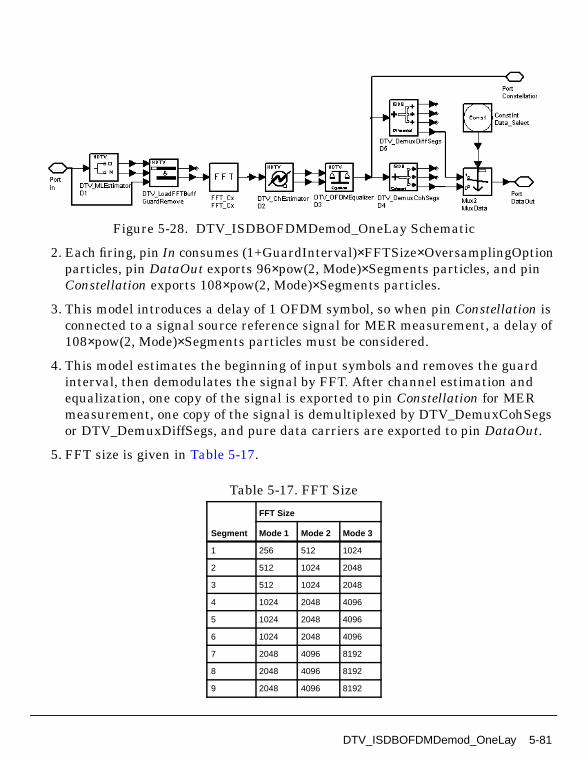
Figure 5-28. DTV_ISDBOFDMDemod_OneLay Schematic
2. Each firing, pin In consumes (1+GuardInterval)×FFTSize×OversamplingOptionparticles, pin DataOut exports 96×pow(2, Mode)×Segments particles, and pinConstellation exports 108×pow(2, Mode)×Segments particles.
3. This model introduces a delay of 1 OFDM symbol, so when pin Constellation isconnected to a signal source reference signal for MER measurement, a delay of108×pow(2, Mode)×Segments particles must be considered.
4. This model estimates the beginning of input symbols and removes the guardinterval, then demodulates the signal by FFT. After channel estimation andequalization, one copy of the signal is exported to pin Constellation for MERmeasurement, one copy of the signal is demultiplexed by DTV_DemuxCohSegsor DTV_DemuxDiffSegs, and pure data carriers are exported to pin DataOut.
5. FFT size is given in Table 5-17.
Table 5-17. FFT Size
Segment
FFT Size
Mode 1 Mode 2 Mode 3
1 256 512 1024
2 512 1024 2048
3 512 1024 2048
4 1024 2048 4096
5 1024 2048 4096
6 1024 2048 4096
7 2048 4096 8192
8 2048 4096 8192
9 2048 4096 8192
DTV_ISDBOFDMDemod_OneLay 5-81

ISDB-T Components
6. The input signal starts with the first symbol of an ISDB-T signal frame.
7. Parameter Details
Mode specifies transmission mode 2K (Mode 1), 4K (Mode 2), or 8K (Mode 3)defined in ISDB-T.
MappingMode specifies signal constellation and mapping: DQPSK, QPSK,16QAM, or 64QAM.
Segments specifies the number of segments per layer.
GuardInterval specifies the guard interval (also called cyclic extension) lengthfor each symbol, as a fraction (1/32, 1/16, 1/8, or 1/4) of the FFT time period. Thevalue must match the guard interval length actually used in the input signal inorder for the demodulation to work properly.
OversamplingOption specifies the oversampling ratio of the transmissionsignal. Ratios 1, 2, 4, 8, 16, and 32 are supported in this model. For example, ifRatio 2 is selected, FFT size of the demodulator will double; if Ratio 1 is selectedno oversampling will be performed.
References
[1]ARIB STD-B31 Version 1.5, Transmission System for Digital TerrestrialTelevision Broadcasting, July 29, 2003.
10 2048 4096 8192
11 2048 4096 8192
12 2048 4096 8192
13 2048 4096 8192
Table 5-17. FFT Size
Segment
FFT Size
Mode 1 Mode 2 Mode 3
5-82 DTV_ISDBOFDMDemod_OneLay

DTV_ISDBOFDMMod_OneLay
Description One-layer OFDM modulation of ISDB-TLibrary DTV, ISDB-T
Parameters
Pin Inputs
Pin Outputs
Name Description Default Sym Type Range
Mode transmission mode: Mode1, Mode 2, Mode 3
Mode 1 enum
MappingMode signal constellations andmapping: DQPSK, QPSK,QAM-16, QAM-64
DQPSK enum
Segments number of segments perlayer
13 int [1, 13]
GuardInterval guard interval (fractionalFFT size)
1/32 real [0, 1]
OversamplingOption oversampling ratio option:Ratio 1, Ratio 2, Ratio 4,Ratio 8, Ratio 16, Ratio 32
Ratio 1 S enum
Pin Name Description Signal Type
1 Data input data complex
2 TMCC TMCC information for different layers complex
3 AC1 ancillary information for auxiliary channel 1 complex
4 AC2 ancillary information for auxiliary channel 2 (DQPSKonly)
complex
Pin Name Description Signal Type
5 ISDBT_signal ISDB-T signal complex
6 constellation constellation signal before IFFT complex
DTV_ISDBOFDMMod_OneLay 5-83

ISDB-T Components
Notes/Equations
1. This subnetwork model performs OFDM frame adaptation, IFFT, and guardinterval insertion for ISDB-T one-layer transmission.
The schematic for this subnetwork is shown in Figure 5-29.
Figure 5-29. DTV_ISDBOFDMMod_OneLay Schematic
2. For differential modulation (DQPSK), the CP serves as the SP (scattered pilot)of a synchronous modulation segment when the differential modulationsegment at the lowermost frequency is adjacent to one of the synchronousmodulation segments. The CP is therefore provided at this low-frequency end.
The TMCC and AC (AC1, AC2) carriers are randomly arranged with regard tofrequency in order to reduce degradation caused by periodic dips on channelcharacteristics under a multi-path environment. AC carriers not only serve asAC pilot signals, but can be used as carriers for additional transmission controlinformation.
Note that AC1 carriers for differential modulation segments are arranged atthe same positions as those for the synchronous modulation segments.
3. For synchronous modulation (QPSK, 16QAM, 64QAM), the SP is inserted into asegment once every 12 carriers in the carrier direction, and once every 4symbols in the symbol direction. The AC1 carrier arrangement for synchronousmodulation is the same as that for differential modulation. (AC2 is used fordifferential modulation only).
References
[1]ARIB STD-B31 Version 1.5, Transmission System for Digital TerrestrialTelevision Broadcasting, July 29, 2003.
5-84 DTV_ISDBOFDMMod_OneLay

DTV_ISDBOneLayReceiver
Description ISDB-T one-layer receiverLibrary DTV, ISDB-T
Parameters
Pin Inputs
Name Description Default Type Range
Mode transmission mode: Mode1, Mode 2, Mode 3
Mode 1 enum
OversamplingOption oversampling ratio option:Ratio 1, Ratio 2, Ratio 4,Ratio 8, Ratio 16, Ratio 32
Ratio 1 enum
GuardInterval guard interval (fractionalFFT size)
1/32 real [0, 1]
CodeRate convolutional code rate:DTV 1/2, DTV 2/3, DTV3/4, DTV 5/6, DTV 7/8
DTV 1/2 enum
MappingMode signal constellations andmapping: DQPSK, QPSK,QAM-16, QAM-64
DQPSK enum
TimeInterlv length of time interleaver:I_000, I_001, I_010, I_011,I_100
I_000 enum
Segments number of segments: Seg0 is not allowed, Seg 1,Seg 2, Seg 3, Seg 4, Seg5, Seg 6, Seg 7, Seg 8,Seg 9, Seg 10, Seg 11,Seg 12, Seg 13
Seg 13 enum
TrunLen path memory truncationlength of Viterbi decodingalgorithm, in bytes
10 int [5, ∞)
Pin Name Description Signal Type
1 In input OFDM baseband signal complex
DTV_ISDBOneLayReceiver 5-85

ISDB-T Components
Pin Outputs
Notes/Equations
1. This 1-layer ISDB-T baseband receiver subnetwork performs 1-layer OFDMdemodulation, frequency deinterleaving, time deinterleaving, demapping andbit-wise deinterleaving, inner decoding (Viterbi), byte-wise deinterleaving,derandomizing and Reed-Solomon decoding.
The schematic for this subnetwork is shown in Figure 5-30.
Figure 5-30. DTV_ISDBOneLayReceiver Schematic
2. FFT size is given in Table 5-18.
Pin Name Description Signal Type
2 constellation signal constellation after OFDM demodulation complex
3 Bytes_BefRSD information bytes before RS decoder int
4 Bytes_Decoded information bytes after RS decoder int
Table 5-18. FFT Size
Segment
FFT Size
Mode 1 Mode 2 Mode 3
1 256 512 1024
2 512 1024 2048
3 512 1024 2048
4 1024 2048 4096
5 1024 2048 4096
6 1024 2048 4096
7 2048 4096 8192
8 2048 4096 8192
9 2048 4096 8192
10 2048 4096 8192
5-86 DTV_ISDBOneLayReceiver
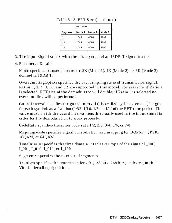
3. The input signal starts with the first symbol of an ISDB-T signal frame.
4. Parameter Details
Mode specifies transmission mode 2K (Mode 1), 4K (Mode 2), or 8K (Mode 3)defined in ISDB-T.
OversamplingOption specifies the oversampling ratio of transmission signal.Ratios 1, 2, 4, 8, 16, and 32 are supported in this model. For example, if Ratio 2is selected, FFT size of the demodulator will double; if Ratio 1 is selected nooversampling will be performed.
GuardInterval specifies the guard interval (also called cyclic extension) lengthfor each symbol, as a fraction (1/32, 1/16, 1/8, or 1/4) of the FFT time period. Thevalue must match the guard interval length actually used in the input signal inorder for the demodulation to work properly.
CodeRate specifies the inner code rate 1/2, 2/3, 3/4, 5/6, or 7/8.
MappingMode specifies signal constellation and mapping for DQPSK, QPSK,16QAM, or 64QAM.
TimeInterlv specifies the time domain interleaver type of the signal: I_000,I_001, I_010, I_011, or I_100.
Segments specifies the number of segments.
TrunLen specifies the truncation length (1×8 bits, 2×8 bits), in bytes, in theViterbi decoding algorithm.
11 2048 4096 8192
12 2048 4096 8192
13 2048 4096 8192
Table 5-18. FFT Size (continued)
Segment
FFT Size
Mode 1 Mode 2 Mode 3
DTV_ISDBOneLayReceiver 5-87

ISDB-T Components
5. Output Delays
DTV_ISDBChDecoder consists of Viterbi decoder, byte-wise deinterleaver andderandomizer. Viterbi decoder introduces different delay for different pathmemory truncation length (TrunLen parameter). For BER measurementsynchronization, the delay between byte-interleaver and byte deinterleavermust be adjusted to a multiple of 12 bytes, and the delay between randomizerand derandomizer must be adjusted to a multiple of 204 bytes. Here, bothdelays are adjusted to a multiple of 204 bytes.
The basic delay calculation of an ISDB-T receiver is shown in Figure 5-31.
Assuming MapRate=2, 2, 4, 6, CodeRateFrac=1/2, 2/3, 3/4, 5/6, 7/8, thenMapRate[MappingMode+1] represents the bit number mapped onto one datacarrier, and CodeRateFrac[CodeRate+1] represents the inner coder rate, we get:
Figure 5-31. Delay Calculation of ISDB-T Receiver
where
D_OFDMMod*108/96 is the delay between the Constellation pins ofDTV_ISDBOneLaySource and DTV_ISDBOneLayReceiver.
D_AfterDerandomize is the delay between pins Bytes_AftRSC inDTV_ISDBOneLaySource and Bytes_BefRSD in DTV_ISDBOneLayReceiver.
D_AfterRSDecoder is the delay between pins Bytes_Uncoded inDTV_ISDBOneLaySource and Bytes_Decoded in DTV_ISDBOneLayReceiver.
When connecting the receiver to the signal source in MER and BERmeasurements, reference signal from the signal generator must be delayedaccording to the formula shown in Figure 5-31.
5-88 DTV_ISDBOneLayReceiver

References
[1]ARIB STD-B31 Version 1.5, Transmission System for Digital TerrestrialTelevision Broadcasting, July 29, 2003.
DTV_ISDBOneLayReceiver 5-89
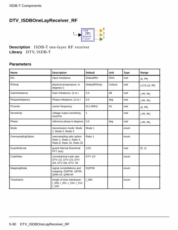
ISDB-T Components
DTV_ISDBOneLayReceiver_RF
Description ISDB-T one-layer RF receiverLibrary DTV, ISDB-T
Parameters
Name Description Default Unit Type Range
RIn input resistance DefaultRIn Ohm real (0, ∞)
RTemp physical temperature, indegrees C
DefaultRTemp Celsius real [-273.15, ∞)
GainImbalance Gain imbalance, Q vs I 0.0 dB real (-∞, ∞)
PhaseImbalance Phase imbalance, Q vs I 0.0 deg real (-∞, ∞)
FCarrier carrier frequency 611.0MHz Hz real (0, ∞)
Sensitivity voltage output sensitivity,Vout/Vin
1 real (-∞, ∞)
Phase reference phase in degrees 0.0 deg real (-∞, ∞)
Mode transmission mode: Mode1, Mode 2, Mode 3
Mode 1 enum
OversamplingOption oversampling ratio option:Ratio 1, Ratio 2, Ratio 4,Ratio 8, Ratio 16, Ratio 32
Ratio 1 enum
GuardInterval guard interval (fractionalFFT size)
1/32 real [0, 1]
CodeRate convolutional code rate:DTV 1/2, DTV 2/3, DTV3/4, DTV 5/6, DTV 7/8
DTV 1/2 enum
MappingMode signal constellations andmapping: DQPSK, QPSK,QAM-16, QAM-64
DQPSK enum
TimeInterlv length of time interleaver:I_000, I_001, I_010, I_011,I_100
I_000 enum
5-90 DTV_ISDBOneLayReceiver_RF

Pin Inputs
Pin Outputs
Notes/Equations
1. This subnetwork model is a 1-layer ISDB-T RF receiver.
The schematic for this subnetwork is shown in Figure 5-32.
Segments number of segments: Seg0 is not allowed, Seg 1,Seg 2, Seg 3, Seg 4, Seg5, Seg 6, Seg 7, Seg 8,Seg 9, Seg 10, Seg 11,Seg 12, Seg 13
Seg 13 enum
TrunLen path memory truncationlength of Viterbi decodingalgorithm, in bytes
10 int [5, ∞)
Pin Name Description Signal Type
1 RF received OFDM signal to be demodulated timed
Pin Name Description Signal Type
2 constellation signal constellation after OFDM demodulation complex
3 Bytes_BefRSD information bytes before RS decoder int
4 Bytes_Decoded information bytes after RS decoder int
Name Description Default Unit Type Range
DTV_ISDBOneLayReceiver_RF 5-91

ISDB-T Components
Figure 5-32. DTV_ISDBOneLayReceiver_RF Schematic
2. The input timed signal is demodulated from RF to baseband and fed to theISDB-T 1-layer receiver.
3. The baseband receiver (DTV_ISDBOneLayReceiver) schematic is shown inFigure 5-33.
Figure 5-33. DTV_ISDBOneLayReceiver Schematic
4. FFT size is given in Table 5-19.
5-92 DTV_ISDBOneLayReceiver_RF

5. The input signal starts with the first symbol of an ISDB-T signal frame.
6. Baseband Parameter Details
Mode specifies transmission mode 2K (Mode 1), 4K (Mode 2), or 8K (Mode 3)defined in ISDB-T.
OversamplingOption specifies the oversampling ratio of the transmissionsignal. Ratios 1, 2, 4, 8, 16, and 32 are supported in this model. For example, ifRatio 2 is selected, FFT size of the demodulator will double; if Ratio 1 is selectedno oversampling will be performed.
GuardInterval specifies the guard interval (also called cyclic extension) lengthfor each symbol, as a fraction (1/32, 1/16, 1/8, or 1/4) of the FFT time period. Thevalue must match the guard interval length actually used in the input signal inorder for the demodulation to work properly.
CodeRate specifies the inner code rate 1/2, 2/3, 3/4, 5/6, or 7/8.
MappingMode specifies signal constellation and mapping for DQPSK, QPSK,16QAM, or 64QAM.
TimeInterlv specifies the time domain interleaver type of the signal: I_000,I_001, I_010, I_011, or I_100.
Table 5-19. FFT Size
Segment
FFT Size
Mode 1 Mode 2 Mode 3
1 256 512 1024
2 512 1024 2048
3 512 1024 2048
4 1024 2048 4096
5 1024 2048 4096
6 1024 2048 4096
7 2048 4096 8192
8 2048 4096 8192
9 2048 4096 8192
10 2048 4096 8192
11 2048 4096 8192
12 2048 4096 8192
13 2048 4096 8192
DTV_ISDBOneLayReceiver_RF 5-93

ISDB-T Components
Segments specifies the number of segments.
TrunLen specifies the truncation length (1×8 bits, 2×8 bits), in bytes, in theViterbi decoding algorithm.
7. Output Delays
DTV_ISDBChDecoder consists of Viterbi decoder, byte-wise deinterleaver andderandomizer. Viterbi decoder introduces different delay for different pathmemory truncation length (TrunLen parameter). For BER measurementsynchronization, the delay between byte-interleaver and byte deinterleavermust be adjusted to a multiple of 12 bytes and the delay between randomizerand derandomizer must be adjusted to a multiple of 204 bytes. Here, bothdelays are adjusted to a multiple of 204bytes.
The basic delay calculation of an ISDB-T receiver is shown in Figure 5-34.
Assuming MapRate=2, 2, 4, 6, CodeRateFrac=1/2, 2/3, 3/4, 5/6, 7/8, thenMapRate[MappingMode+1] represents the bit number mapped onto one datacarrier, and CodeRateFrac[CodeRate+1] represents the inner coder rate, we get:
Figure 5-34. Delay Calculation of ISDB-T Receiver
where
D_OFDMMod*108/96 is the delay between the Constellation pins inDTV_ISDBOneLaySource and DTV_ISDBOneLayReceiver.
D_AfterDerandomize is the delay between pins Bytes_AftRSC inDTV_ISDBOneLaySource and Bytes_BefRSD in DTV_ISDBOneLayReceiver.
D_AfterRSDecoder is the delay between pins Bytes_Uncoded inDTV_ISDBOneLaySource and Bytes_Decoded in DTV_ISDBOneLayReceiver.
5-94 DTV_ISDBOneLayReceiver_RF

When connecting the receiver to the signal source in MER and BERmeasurements, the reference signal from the signal generator must be delayedaccording to the formula in Figure 5-34.
8. RF Parameter Details
GainImbalance and PhaseImbalance add certain impairments to the idealoutput RF signal. Impairments are added as described here.
The unimpaired RF I and Q envelope voltages have gain and phase imbalanceapplied. The RF is given by:
where V1(t) is the in-phase RF envelope, V2(t) is the quadrature phase RFenvelope, g is the gain imbalance
and, φ (in degrees) is the phase imbalance.
References
[1]ARIB STD-B31 Version 1.5, Transmission System for Digital TerrestrialTelevision Broadcasting, July 29, 2003.
V3 t( ) A V1 t( ) ωct( )cos gV2 t( ) ωctφπ180---------+
sin– =
g 10
GainImbalance20
-----------------------------------------------
=
DTV_ISDBOneLayReceiver_RF 5-95

ISDB-T Components
DTV_ISDBOneLaySource
Description ISDB-T one-layer signal sourceLibrary DTV, ISDB-T
Parameters
Pin Inputs
Pin Outputs
Name Description Default Type Range
Mode transmission mode: Mode1, Mode 2, Mode 3
Mode 1 enum
OversamplingOption oversampling ratio option:Ratio 1, Ratio 2, Ratio 4,Ratio 8, Ratio 16, Ratio 32
Ratio 1 enum
GuardInterval guard interval (fractionalFFT size)
1/32 real [0, 1]
CodeRate convolutional Code Rate:DTV 1/2, DTV 2/3, DTV3/4, DTV 5/6, DTV 7/8
DTV 1/2 enum
MappingMode signal constellations andmapping: DQPSK, QPSK,QAM-16, QAM-64
DQPSK enum
TimeInterlv length of time interleaver:I_000, I_001, I_010, I_011,I_100
I_000 enum
Segments number of segments: Seg0 is not allowed, Seg 1,Seg 2, Seg 3, Seg 4, Seg5, Seg 6, Seg 7, Seg 8,Seg 9, Seg 10, Seg 11,Seg 12, Seg 13
Seg 13 enum
Pin Name Description Signal Type
1 Data input data int
Pin Name Description Signal Type
2 ISDBT_signal ISDB-T signal complex
5-96 DTV_ISDBOneLaySource

Notes/Equations
1. This subnetwork model provides an ISDB-T one-layer signal source. Itgenerates one OFDM symbol each firing.
The schematic for this subnetwork is shown in Figure 5-35.
Figure 5-35. DTV_ISDBOneLaySource Schematic
2. A transport stream (TS) input (defined in MPEG-2 Systems) is subjected tomultiple channel-coding steps, bit-wise interleaving and data mapping, timeinterleaving, frequency interleaving, and is sent as a single OFDM signal.
The ISDB-T signal source format follows the ISDB-T specification. Figure 5-36is functional block diagram of the ISDB-T baseband system.
3 constellation constellation signal before IFFT complex
4 Bytes_AftRSC information bytes after RS coder int
Pin Name Description Signal Type
DTV_ISDBOneLaySource 5-97

ISDB-T Components
Figure 5-36. ISDB-T Baseband System Functional Block Diagram
The transmission spectrum of television broadcasting consists of 13 successiveOFDM blocks (OFDM segments); each bandwidth equals 1/14 of a televisionbroadcast channel bandwidth. An OFDM-segment carrier configuration thatallows connection of multiple segments makes it possible to provide anappropriate transmission bandwidth in terms of units of segment width for thetarget media; at the same time it allows use of the same receiver for ISDB-Tand ISDB-TSB (Transmission System for Digital Terrestrial SoundBroadcasting).
In consideration of the suitability of the distance between SFN stations and therobustness to Doppler shift during mobile-reception, ISDB-T offers threedifferent spacings between OFDM carrier frequencies; these spacings areidentified as system modes. Spacings between OFDM carrier frequencies areapproximately 4, 2, and 1 kHz in modes 1, 2, and 3, respectively. The number ofcarriers varies depending on the mode, but the information bit rate that can betransmitted remains the same in all modes.
TMCC signals convey control information that assists in receiver operations.
3. Parameter Details
Mode specifies transmission mode 1, 2, or 3 (defined in ISDB-T specification).
OversamplingOption specifies the oversampling ratio of the transmissionsignal. Ratios 1, 2, 4, 8, 16, and 32 are supported in this source.
MPEG-2Multiplexer
TSRe-
OuterCode
(204,188)
Division ofTS into
HierarchicalLevels
ByteInterleaving
ConvolutionalCoding
Byte→BitsMSB First
Bits→ByteMSB First
DelayAdjustment
EnergyDispersal
Byte→BitsMSB First
ByteInterleaving
ConvolutionalCoding
Byte→BitsMSB First
Bits→ByteMSB First
DelayAdjustment
EnergyDispersal
Byte→BitsMSB First
ByteInterleaving
ConvolutionalCoding
Byte→BitsMSB First
Bits→ByteMSB First
DelayAdjustment
EnergyDispersal
Byte→BitsMSB First
Multiply
Carrier Modulation
Bit Interleaving Mapping
Carrier Modulation
Bit Interleaving Mapping
Carrier Modulation
Bit Interleaving Mapping
Hierarchical Time FrequencyOFDM
Interleaving Interleaving IFFTGuard
LevelCombining Structure
FrameAdditionInterval
Pilot Signals
TMCC Signal
5-98 DTV_ISDBOneLaySource

GuardInterval specifies the guard interval (also called cyclic extension) lengthfor each symbol time, as a fraction of the FFT time period. Guard intervals 1/4,1/8, 1/16, and 1/32 are defined in the ISDB-T specification; in this source,GuardInterval is defined as a real value between 0.0 and 1.0. Users can set anyvalue between 0.0 and 1.0, not just 1/4, 1/8, 1/16 and 1/32. The value mustmatch the guard interval length actually used in the input signal sodemodulation will work properly.
CodeRate is defined as code rate of stream; rates 1/2, 2/3, 3/4, 5/6 and 7/8 aresupported in this source.
MappingMode specifies signal constellations and ISDB-T signal sourcemapping; modes DQPSK, QPSK, 16-QAM, and 64-QAM are supported in thissource.
TimeInterlv specifies the time interleaving length. There are five differentvalues for each mode.
Segments specifies the number of segments. Recommended IFFT sizes aregiven with regard to the total number of segments listed in Table 5-20.
References
[1]ARIB STD-B31 Version 1.5, Transmission System for Digital TerrestrialTelevision Broadcasting, July 29, 2003.
Table 5-20. Number of Segments and IFFT Sizes
No. ofSegments
Mode 1 Mode 2 Mode 3
IFFTOrder IFFT Size
IFFTOrder IFFT Size
IFFTOrder IFFT Size
1 8 256 9 512 10 1024
2, 3 9 512 10 1024 11 2048
4, 5, 6 10 1024 11 2048 12 4096
7, 8, 9, 10,11, 12, 13
11 2048 12 4096 13 8192
DTV_ISDBOneLaySource 5-99

ISDB-T Components
DTV_ISDBOneLaySource_RF
Description ISDB-T one-layer RF signal sourceLibrary DTV, ISDB-T
Parameters
Name Description Default Unit Type Range
ROut output resistance DefaultROut Ohm real (0, ∞)
RTemp physical temperature, indegrees C
DefaultRTemp Celsius real [-273.15, ∞)
FCarrier carrier frequency 611.0MHz Hz real (0, ∞)
Power modulator output power 40mW W real (0, ∞)
BasicSamplingRate basic sampling rate (2048/252.0)MHz Hz real (0, ∞)
MirrorSpectrum Mirror spectrum aboutcarrier? NO, YES
NO enum
GainImbalance Gain imbalance, Q vs I 0.0 dB real (-∞, ∞)
PhaseImbalance Phase imbalance, Q vs I 0.0 deg real (-∞, ∞)
I_OriginOffset I origin offset (percent) 0.0 real (-∞, ∞)
Q_OriginOffset Q origin offset (percent) 0.0 real (-∞, ∞)
IQ_Rotation IQ rotation 0.0 deg real (-∞, ∞)
Mode transmission mode: Mode1, Mode 2, Mode 3
Mode 1 enum
OversamplingOption oversampling ratio option:Ratio 1, Ratio 2, Ratio 4,Ratio 8, Ratio 16, Ratio 32
Ratio 1 enum
GuardInterval guard interval (fractionalFFT size)
1/32 real [0, 1]
CodeRate convolutional Code Rate:DTV 1/2, DTV 2/3, DTV3/4, DTV 5/6, DTV 7/8
DTV 1/2 enum
MappingMode signal constellations andmapping: DQPSK, QPSK,QAM 16, QAM 64
DQPSK enum
5-100 DTV_ISDBOneLaySource_RF

Pin Outputs
Notes/Equations
1. This subnetwork model integrates an RF modulator with the baseband signalsource. The ISDB-T baseband signal is fed into the RF modulator. The RFsignal is timed signal after RF modulation.
The schematic for this subnetwork is shown in Figure 5-37.
TimeInterlv length of time interleaver:I_000, I_001, I_010, I_011,I_100
I_000 enum
Segments number of segments: Seg0 is not allowed, Seg 1,Seg 2, Seg 3, Seg 4, Seg5, Seg 6, Seg 7, Seg 8,Seg 9, Seg 10, Seg 11,Seg 12, Seg 13
Seg 13 enum
DataType payload data type: PN9,PN15, FIX4, _4_1_4_0,_8_1_8_0, _16_1_16_0,_32_1_32_0, _64_1_64_0
PN9 enum
Pin Name Description Signal Type
1 RF RF signal timed
2 ISDBT_signal ISDB-T signal complex
3 constellation constellation signal before IFFT complex
4 Bytes_AftRSC information bytes after RS coder int
5 Bytes_Uncoded information bytes of transport packet int
Name Description Default Unit Type Range
DTV_ISDBOneLaySource_RF 5-101

ISDB-T Components
Figure 5-37. DTV_ISDBOneLaySource_RF Schematic
2. The ISDB-T signal source format follows the ISDB-T specification. Theschematic for DTV_ISDBOneLaySource is shown in Figure 5-38.
Figure 5-38. DTV_ISDBOneLaySource Schematic
5-102 DTV_ISDBOneLaySource_RF

The ISDB-T baseband system functional block diagram is shown in Figure 5-39.
Figure 5-39. Baseband System Functional Block Diagram
3. Parameter Details
FCarrier defines the RF frequency for the ISDB signal.
Power defines the power level for FCarrier.
BasicSamplingRate indicates basic sampling rate.
The MirrorSpectrum is used to conjugate the input signal (when set to YES)before any other processing is done.
GainImbalance, PhaseImbalance, I_OriginOffset, Q_OriginOffset, andIQ_Rotation parameters are used to add certain impairments to the idealoutput RF signal. Impairments are added in the order described here.
The unimpaired RF I and Q envelope voltages have gain and phase imbalanceapplied. RF is given by:
where
A is a scaling factor that depends on the Power and ROut parametersspecified by the user
V1(t) is the in-phase RF envelope
MPEG-2Multiplexer
TSRe-
OuterCode
(204,188)
Division ofTS into
HierarchicalLevels
ByteInterleaving
ConvolutionalCoding
Byte→BitsMSB First
Bits→ByteMSB First
DelayAdjustment
EnergyDispersal
Byte→BitsMSB First
ByteInterleaving
ConvolutionalCoding
Byte→BitsMSB First
Bits→ByteMSB First
DelayAdjustment
EnergyDispersal
Byte→BitsMSB First
ByteInterleaving
ConvolutionalCoding
Byte→BitsMSB First
Bits→ByteMSB First
DelayAdjustment
EnergyDispersal
Byte→BitsMSB First
Multiply
Carrier Modulation
Bit Interleaving Mapping
Carrier Modulation
Bit Interleaving Mapping
Carrier Modulation
Bit Interleaving Mapping
Hierarchical Time FrequencyOFDM
Interleaving Interleaving IFFTGuard
LevelCombining Structure
FrameAdditionInterval
Pilot Signals
TMCC Signal
V3 t( ) A V1 t( ) ωct( )cos gV2 t( ) ωctφπ180---------+
sin– =
DTV_ISDBOneLaySource_RF 5-103

ISDB-T Components
V2(t) is the quadrature phase RF envelope
g is the gain imbalance
φ (in degrees) is the phase imbalance
The V3(t) signal is rotated by IQ_Rotation degrees. I_OriginOffset andQ_OriginOffset are then applied to the rotated signal. Note that the amountsspecified are percentages with respect to the output rms voltage. The outputrms voltage is given by sqrt(2×ROut×Power). Mode is used to selecttransmission mode of 1, 2, or 3 defined in ISDB-T.
OversamplingOption indicates the oversampling ratio of transmission signal.Oversampling ratios 1, 2, 4, 8, 16, and 32 are supported in this source.OversamplingOption is Ratio 1, Ratio 2, ... , Ratio 32, which indicates theoversampling ratio of transmission signal is 1, 2, ... , 32.
GuardInterval specifies the guard interval (also called cyclic extension) lengthfor each symbol time, as a fraction of the FFT time period. Guard intervals 1/4,1/8, 1/16, and 1/32 are defined in the ISDB-T specification; in this source,GuardInterval is specified as a real value between 0.0 and 1.0. Users can setany value between 0.0 and 1.0; the value must match the guard interval lengthactually used in the input signal in order for the demodulation to work properly.
CodeRate is defined as code rate of stream. Rates 1/2, 2/3, 3/4, 5/6, and 7/8 aresupported in this source.
MappingMode specifies signal constellation and ISDB-T signal source mapping.Modes DQPSK, QPSK, 16-QAM, and 64-QAM are supported in this source.
TimeInterlv specifies the time interleaving length. Time interleaving lengths,based on mode, are given in Table 5-21.
g 10
GainImbalance20
-----------------------------------------------
=
5-104 DTV_ISDBOneLaySource_RF

Segments specifies the number of segments. Recommended IFFT sizes aregiven in Table 5-22.
References
[1]ARIB STD-B31 Version 1.5, Transmission System for Digital TerrestrialTelevision Broadcasting, July 29, 2003.
Table 5-21. Time Interleaving Length
TimeInterlvTime InterleavingLength I (Mode 1)
Time InterleavingLength I (Mode 2)
Time InterleavingLength I (Mode 3)
I_000 0 0 0
I_001 4 2 1
I_010 8 4 2
I_011 16 8 4
I_100 32 16 8
Table 5-22. Number of Segments and IFFT Sizes
No. ofSegments
Mode 1 Mode 2 Mode 3
IFFT Order IFFT Size IFFT Order IFFT Size IFFT Order IFFT Size
1 8 256 9 512 10 1024
2, 3 9 512 10 1024 11 2048
4, 5, 6 10 1024 11 2048 12 4096
7, 8, 9, 10,11, 12, 13
11 2048 12 4096 13 8192
DTV_ISDBOneLaySource_RF 5-105

ISDB-T Components
DTV_ISDBPartialReceiver_RF
Description ISDB-T one-segment RF receiverLibrary DTV, ISDB-T
Parameters
Name Description Default Unit Type Range
RIn input resistance DefaultRIn Ohm real (0, ∞)
RTemp physical temperature, indegrees C
DefaultRTemp Celsius real [-273.15, ∞)
GainImbalance Gain imbalance, Q vs I 0.0 dB real (-∞, ∞)
PhaseImbalance Phase imbalance, Q vs I 0.0 deg real (-∞, ∞)
FCarrier carrier frequency 611.0MHz Hz real (0, ∞)
Sensitivity voltage output sensitivity,Vout/Vin
1 real (-∞, ∞)
Phase reference phase in degrees 0.0 deg real (-∞, ∞)
Mode transmission mode: Mode1, Mode 2, Mode 3
Mode 1 enum
OversamplingOption oversampling ratio option:Ratio 1, Ratio 2, Ratio 4,Ratio 8, Ratio 16, Ratio 32
Ratio 1 enum
GuardInterval guard interval (fractionalFFT size)
1/32 real [0, 1]
CodeRate convolutional code rate:DTV 1/2, DTV 2/3, DTV3/4, DTV 5/6, DTV 7/8
DTV 1/2 enum
MappingMode signal constellations andmapping: DQPSK, QPSK,QAM-16, QAM-64
DQPSK enum
TimeInterlv length of time interleaver:I_000, I_001, I_010, I_011,I_100
I_000 enum
TrunLen path memory truncationlength of Viterbi decodingalgorithm, in bytes
10 int [5, ∞)
5-106 DTV_ISDBPartialReceiver_RF

Pin Inputs
Pin Outputs
Notes/Equations
1. This is a 1-segment ISDB-T RF receiver.
The schematic for this subnetwork is shown in Figure 5-40.
Figure 5-40. DTV_ISDBPartialReceiver_RF Schematic
2. The input timed signal is demodulated from RF to baseband and downsampledby a factor of 8; the downsampled signal is fed to the ISDB-T 1-layer receiverwhose segment number is set to 1.
3. FFT size of the OFDM demodulator in DTV_ISDBOneLayReceiver is 256 whenOversamplingOption is set to Ratio 1.
4. The input signal starts with the first symbol of an ISDB-T signal frame.
5. The baseband receiver (DTV_ISDBOneLayReceiver) schematic is shown inFigure 5-41.
Pin Name Description Signal Type
1 RF received OFDM signal to be demodulated timed
Pin Name Description Signal Type
2 constellation signal constellation after OFDM demodulation complex
3 Bytes_BefRSD information bytes before RS decoder int
4 Bytes_Decoded information bytes after RS decoder int
DTV_ISDBPartialReceiver_RF 5-107

ISDB-T Components
Figure 5-41. DTV_ISDBOneLayReceiver Schematic
6. Baseband Parameter Details
Mode specifies transmission mode 2K (Mode 1), 4K (Mode 2), or 8K (Mode 3)defined in ISDB-T.
OversamplingOption specifies the oversampling ratio of transmission signal.Ratios 1, 2, 4, 8, 16, and 32 are supported in this model. For example, if Ratio 2is selected, FFT size of the demodulator will double; if Ratio 1 is selected nooversampling will be performed.
GuardInterval specifies the guard interval (also called cyclic extension) lengthfor each symbol, as a fraction (1/32, 1/16, 1/8, or 1/4) of the FFT time period. Thevalue must match the guard interval length actually used in the input signal inorder for the demodulation to work properly.
CodeRate specifies the inner code rate 1/2, 2/3, 3/4, 5/6, or 7/8.
MappingMode specifies signal constellation and mapping for DQPSK, QPSK,16QAM, or 64QAM.
TimeInterlv specifies time domain interleaver type of the signal: I_000, I_001,I_010, I_011, or I_100.
TrunLen specifies the truncation length (1×8 bits, 2×8 bits), in bytes, in theViterbi decoding algorithm.
5-108 DTV_ISDBPartialReceiver_RF

7. Output Delays
DTV_ISDBChDecoder consists of Viterbi decoder, byte-wise deinterleaver andderandomizer. Viterbi decoder introduces different delay for different pathmemory truncation length (parameter TrunLen). For BER measurementsynchronization, the delay between byte-interleaver and byte deinterleavermust be adjusted to a multiple of 12 bytes and the delay between randomizerand derandomizer must be adjusted to a multiple of 204 bytes. Here, bothdelays are adjusted to a multiple of 204bytes.
The basic delay calculation of an ISDB-T receiver is shown in Figure 5-42.
Assuming MapRate=2, 2, 4, 6, CodeRateFrac=1/2, 2/3, 3/4, 5/6, 7/8, thenMapRate[MappingMode+1] represents the bit number mapped onto one datacarrier, and CodeRateFrac[CodeRate+1] represents the inner coder rate, we get:
Figure 5-42. Delay Calculation of ISDB-T Partial Receiver
where
D_OFDMMod*108/96 is the delay between the Constellation pins of thesignal source and DTV_ISDBPartialReceiver_RF.
D_AfterDerandomize is the delay between pins Bytes_AftRSC of the signalsource and Bytes_BefRSD in DTV_ISDBPartialReceiver_RF.
D_AfterRSDecoder is the delay between pins Bytes_Uncoded of the signalsource and Bytes_Decoded in DTV_ISDBPartialReceiver_RF.
When connecting the receiver to signal source in MER and BER measurements,reference signal from the signal generator must be delayed according to theformula in Figure 5-42.
DTV_ISDBPartialReceiver_RF 5-109

ISDB-T Components
8. RF Parameter Details
GainImbalance and PhaseImbalance add certain impairments to the idealoutput RF signal. Impairments are added as described here.
The unimpaired RF I and Q envelope voltages have gain and phase imbalanceapplied. The RF is given by:
where V1(t) is the in-phase RF envelope, V2(t) is the quadrature phase RFenvelope, g is the gain imbalance
and, φ (in degrees) is the phase imbalance.
References
[1]ARIB STD-B31 Version 1.5, Transmission System for Digital TerrestrialTelevision Broadcasting, July 29, 2003.
V3 t( ) A V1 t( ) ωct( )cos gV2 t( ) ωctφπ180---------+
sin– =
g 10
GainImbalance20
-----------------------------------------------
=
5-110 DTV_ISDBPartialReceiver_RF

DTV_ISDBTMCC
Description ISDB-T transmission and multiplexing configuration control signalLibrary DTV, ISDB-T
Parameters
Name Description Default Type Range
InitiBit initialization bit for theDBPSK modulation (1 bit)
0 int 0, 1
SynchWord synchronization word (16bits): W0, W1
W0 enum
SegmentDescriptor segment descriptor (3 bits):Differential, Coherent
Differential enum
SystemDescriptor system description (2 bits):ISDB-T, ISDB-TSB,Reserved Des 2, ReservedDes 3
ISDB-T enum
CountDownIndex index for transmissionparameter change (4 bits):Ordinary, Frames 15,Frames 14, Frames 13,Frames 12, Frames 11,Frames 10, Frames 9,Frames 8, Frames 7,Frames 6, Frames 5,Frames 4, Frames 3,Frames 2, Frames 1
Ordinary enum
AlarmBroadcastStartFlag start flag foremergency-alarmbroadcasting (1 bit): Nostartup control, Startupcontrol
No startup control enum
Cur_PartialReceptionFlag current partial receptionlayer (1 bit): Cur Un-used,Cur Used
Cur Used enum
DTV_ISDBTMCC 5-111

ISDB-T Components
Cur_A_MappingMode current signalconstellations andmapping for Layer A (3bits): Cur A DQPSK, Cur AQPSK, Cur A 16QAM, CurA 64QAM, Cur A ReservedMappingMode 1, Cur AReserved MappingMode 2,Cur A ReservedMappingMode 3, Cur AUn-used LayerMappingMode
Cur A DQPSK enum
Cur_A_CodeRate current code rate for LayerA (3 bits): Cur A 1/2, Cur A2/3, Cur A 3/4, Cur A 5/6,Cur A 7/8, Cur A ReservedCodeRate 1, Cur AReserved CodeRate 2, CurA Un-used LayerCodeRate
Cur A 1/2 enum
Cur_A_TimeInterlv_I current length of timeinterleaver for Layer A (3bits): Cur A I 0 0 0, Cur A I4 2 1, Cur A I 8 4 2, Cur A I16 8 4, Cur A I 32 16 8, CurA Reserved I 1, Cur AReserved I 2, Cur AUn-used Layer I
Cur A I 8 4 2 enum
Cur_A_Segments current number ofsegments for Layer A (4bits): Cur A Reserved Seg1, Cur A Seg 1, Cur A Seg2, Cur A Seg 3, Cur A Seg4, Cur A Seg 5, Cur A Seg6, Cur A Seg 7, Cur A Seg8, Cur A Seg 9, Cur A Seg10, Cur A Seg 11, Cur ASeg 12, Cur A Seg 13, CurA Reserved Seg 2, Cur AUn-used Layer Seg
Cur A Seg 13 enum
Cur_B_MappingMode current signalconstellations andmapping for Layer B (3bits): Cur B DQPSK, Cur BQPSK, Cur B 16QAM, CurB 64QAM, Cur B ReservedMappingMode 1, Cur BReserved MappingMode 2,Cur B ReservedMappingMode 3, Cur BUn-used LayerMappingMode
Cur B 16QAM enum
Name Description Default Type Range
5-112 DTV_ISDBTMCC

Cur_B_CodeRate current code rate for LayerB (3 bits): Cur B 1/2, Cur B2/3, Cur B 3/4, Cur B 5/6,Cur B 7/8, Cur B ReservedCodeRate 1, Cur BReserved CodeRate 2, CurB Un-used LayerCodeRate
Cur B 1/2 enum
Cur_B_TimeInterlv_I current length of timeinterleaver for Layer B (3bits): Cur B I 0 0 0, Cur B I4 2 1, Cur B I 8 4 2, Cur B I16 8 4, Cur B I 32 16 8, CurB Reserved I 1, Cur BReserved I 2, Cur BUn-used Layer I
Cur B I 8 4 2 enum
Cur_B_Segments current number ofsegments for Layer B (4bits): Cur B Reserved Seg1, Cur B Seg 1, Cur B Seg2, Cur B Seg 3, Cur B Seg4, Cur B Seg 5, Cur B Seg6, Cur B Seg 7, Cur B Seg8, Cur B Seg 9, Cur B Seg10, Cur B Seg 11, Cur BSeg 12, Cur B Seg 13, CurB Reserved Seg 2, Cur BUn-used Layer Seg
Cur B ReservedSeg 1
enum
Cur_C_MappingMode current signalconstellations andmapping for Layer C (3bits): Cur C DQPSK, Cur CQPSK, Cur C 16QAM, CurC 64QAM, Cur C ReservedMappingMode 1, Cur CReserved MappingMode 2,Cur C ReservedMappingMode 3, Cur CUn-used LayerMappingMode
Cur C 64QAM enum
Cur_C_CodeRate current code rate for LayerC ( 3 bits): Cur C 1/2, CurC 2/3, Cur C 3/4, Cur C5/6, Cur C 7/8, Cur CReserved CodeRate 1, CurC Reserved CodeRate 2,Cur C Un-used LayerCodeRate
Cur C 1/2 enum
Name Description Default Type Range
DTV_ISDBTMCC 5-113

ISDB-T Components
Cur_C_TimeInterlv_I current length of timeinterleaver for Layer C (3bits): Cur C I 0 0 0, Cur C I4 2 1, Cur C I 8 4 2, Cur C I16 8 4, Cur C I 32 16 8, CurC Reserved I 1, Cur CReserved I 2, Cur CUn-used Layer I
Cur C I 8 4 2 enum
Cur_C_Segments current number ofsegments for Layer C (4bits): Cur C Reserved Seg1, Cur C Seg 1, Cur C Seg2, Cur C Seg 3, Cur C Seg4, Cur C Seg 5, Cur C Seg6, Cur C Seg 7, Cur C Seg8, Cur C Seg 9, Cur C Seg10, Cur C Seg 11, Cur CSeg 12, Cur C Seg 13, CurC Reserved Seg 2, Cur CUn-used Layer Seg
Cur C Seg 6 enum
Next_PartialReceptionFlag Next partial reception layer(1 bit): Next Un-used, NextUsed
Next Un-used enum
Next_A_MappingMode Next signal constellationsand mapping for Layer A (3bits): Next A DQPSK, NextA QPSK, Next A 16QAM,Next A 64QAM, Next AReserved MappingMode 1,Next A ReservedMappingMode 2, Next AReserved MappingMode 3,Next A Un-used LayerMappingMode
Next A QPSK enum
Next_A_CodeRate Next code rate for Layer A(3 bits): Next A 1/2, Next A2/3, Next A 3/4, Next A 5/6,Next A 7/8, Next AReserved CodeRate 1,Next A ReservedCodeRate 2, Next AUn-used Layer CodeRate
Next A 1/2 enum
Next_A_TimeInterlv_I Next length of timeinterleaver for Layer A (3bits): Next A I 0 0 0, Next AI 4 2 1, Next A I 8 4 2, NextA I 16 8 4, Next A I 32 16 8,Next A Reserved I 1, NextA Reserved I 2, Next AUn-used Layer I
Next A I 8 4 2 enum
Name Description Default Type Range
5-114 DTV_ISDBTMCC

Next_A_Segments Next number of segmentsfor Layer A (4 bits): Next AReserved Seg 1, Next ASeg 1, Next A Seg 2, NextA Seg 3, Next A Seg 4,Next A Seg 5, Next A Seg6, Next A Seg 7, Next ASeg 8, Next A Seg 9, NextA Seg 10, Next A Seg 11,Next A Seg 12, Next A Seg13, Next A Reserved Seg2, Next A Un-used LayerSeg
Next A ReservedSeg 1
enum
Next_B_MappingMode Next signal constellationsand mapping for Layer B (3bits): Next B DQPSK, NextB QPSK, Next B 16QAM,Next B 64QAM, Next BReserved MappingMode 1,Next B ReservedMappingMode 2, Next BReserved MappingMode 3,Next B Un-used LayerMappingMode
Next B 16QAM enum
Next_B_CodeRate Next code rate for Layer B(3 bits): Next B 1/2, Next B2/3, Next B 3/4, Next B 5/6,Next B 7/8, Next BReserved CodeRate 1,Next B ReservedCodeRate 2, Next BUn-used Layer CodeRate
Next B 1/2 enum
Next_B_TimeInterlv_I Next length of timeinterleaver for Layer B (3bits): Next B I 0 0 0, Next BI 4 2 1, Next B I 8 4 2, NextB I 16 8 4, Next B I 32 16 8,Next B Reserved I 1, NextB Reserved I 2, Next BUn-used Layer I
Next B I 8 4 2 enum
Next_B_Segments Next number of segmentsfor Layer B (4 bits): Next BReserved Seg 1, Next BSeg 1, Next B Seg 2, NextB Seg 3, Next B Seg 4,Next B Seg 5, Next B Seg6, Next B Seg 7, Next BSeg 8, Next B Seg 9, NextB Seg 10, Next B Seg 11,Next B Seg 12, Next B Seg13, Next B Reserved Seg2, Next B Un-used LayerSeg
Next B Seg 6 enum
Name Description Default Type Range
DTV_ISDBTMCC 5-115

ISDB-T Components
Pin Outputs
Next_C_MappingMode Next signal constellationsand mapping for Layer C (3bits): Next C DQPSK, NextC QPSK, Next C 16QAM,Next C 64QAM, Next CReserved MappingMode 1,Next C ReservedMappingMode 2, Next CReserved MappingMode 3,Next C Un-used LayerMappingMode
Next C QPSK enum
Next_C_CodeRate Next code rate for Layer C (3 bits): Next C 1/2, Next C2/3, Next C 3/4, Next C 5/6,Next C 7/8, Next CReserved CodeRate 1,Next C ReservedCodeRate 2, Next CUn-used Layer CodeRate
Next C 1/2 enum
Next_C_TimeInterlv_I Next length of timeinterleaver for Layer C (3bits): Next C I 0 0 0, Next CI 4 2 1, Next C I 8 4 2, NextC I 16 8 4, Next C I 32 168, Next C Reserved I 1,Next C Reserved I 2, NextC Un-used Layer I
Next C I 8 4 2 enum
Next_C_Segments Next number of segmentsfor Layer C (4 bits): Next CReserved Seg 1, Next CSeg 1, Next C Seg 2, NextC Seg 3, Next C Seg 4,Next C Seg 5, Next C Seg6, Next C Seg 7, Next CSeg 8, Next C Seg 9, NextC Seg 10, Next C Seg 11,Next C Seg 12, Next C Seg13, Next C Reserved Seg2, Next C Un-used LayerSeg
Next C Seg 5 enum
FutureUse reserved for future use (allset to "1" 15 bits)
1 1 1 1 1 1 1 1 1 11 1 1 1 1
int array "111111111111111"
Pin Name Description Signal Type
1 TMCC modulated TMCC signal complex
2 TMCC_Bits TMCC bits int
Name Description Default Type Range
5-116 DTV_ISDBTMCC

Notes/Equations
1. This subnetwork model generates a TMCC signal. The TMCC signal providesinformation on how the receiver is to perform demodulation of information suchas the hierarchical configuration and the OFDM-segment transmissionparameters. The TMCC signal is transmitted by the TMCC carrier.
2. The schematic for this subnetwork is shown in Figure 5-43.
Figure 5-43. DTV_ISDBTMCC Schematic
3. TMCC information assists the receiver in demodulating and decoding variousinformation, including system identification, the transmission-parameterswitching indicator, the broadcast emergency-alarm start flag, and current andnext information. Current information represents the current hierarchicalconfiguration and transmission parameters; next information includes thetransmission parameters after switching. The next information can be specifiedor changed before the switching countdown.
4. Because TMCC information is used to specify transmission parameters andcontrol receiver operation, it must be transmitted with greater reliability thanprogram signals. Due to the difficulties involved with a receiver using the sameconcatenated-code decoding circuit for TMCC information and program signals(and because the use of block code is advantageous due to its shorter processingtime) the shortened code (184,102) of the difference cyclic code (273,191) is usedas the error-correction code for TMCC information.
Because the same TMCC signals are transmitted by multiple carriers it ispossible to reduce the required C/N by simply adding these signals, therebyensuring improved reception performance. These error-correction techniquesand the addition process make it possible to receive TMCC signals at a lowerC/N than for program signals.
5. DTV_PackTMCC multiplexes the CDSC-coded TMCC information bits (184bits) and other no-coded 20 bits, which include initialization bit,synchronization of TMCC and system type.
6. DTV_TMCCMod performs DBPSK modulation.
DTV_ISDBTMCC 5-117

ISDB-T Components
References
[1]ARIB STD-B31 Version 1.5, Transmission System for Digital TerrestrialTelevision Broadcasting, July 29, 2003.
5-118 DTV_ISDBTMCC
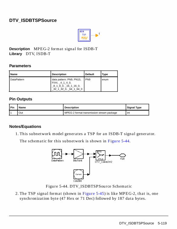
DTV_ISDBTSPSource
Description MPEG-2 format signal for ISDB-TLibrary DTV, ISDB-T
Parameters
Pin Outputs
Notes/Equations
1. This subnetwork model generates a TSP for an ISDB-T signal generator.
The schematic for this subnetwork is shown in Figure 5-44.
Figure 5-44. DTV_ISDBTSPSource Schematic
2. The TSP signal format (shown in Figure 5-45) is like MPEG-2, that is, onesynchronization byte (47 Hex or 71 Dec) followed by 187 data bytes.
Name Description Default Type
DataPattern data pattern: PN9, PN15,FIX4, _4_1_4_0,_8_1_8_0, _16_1_16_0,_32_1_32_0, _64_1_64_0
PN9 enum
Pin Name Description Signal Type
1 Out MPEG-2 format transmission stream package int
DTV_ISDBTSPSource 5-119

ISDB-T Components
Figure 5-45. TSP Signal Format
3. DataPattern specifies the type of data filled in the Data domain shown inFigure 5-45.
• If PN9 is selected, a 511-bit pseudo-random test pattern is generatedaccording to CCITT Recommendation O.153.
• If PN15 is selected, a 32767-bit pseudo-random test pattern is generatedaccording to CCITT Recommendation O.151.
• If FIX4 is selected, a zero-stream is generated.
• If x_1_x_0 is selected, where x equals 4, 8, 16, 32, or 64, a periodic bit streamis generated, with the period being 2x. In one period, the first x bits are onesand the second x bits are zeros.
References
[1]ARIB STD-B31 Version 1.5, Transmission System for Digital TerrestrialTelevision Broadcasting, July 29, 2003.
[2] CCITT, Recommendation O.151(10/92).
[3] CCITT, Recommendation O.153(10/92).
47 Hex(1 byte)
Data(187 bytes)
47 Hex(1 byte)
Data(187 bytes)
47 Hex(1 byte)
Data(187 bytes)
5-120 DTV_ISDBTSPSource

DTV_ISDBThreeLayReceiver
Description ISDB-T three-layer receiverLibrary DTV, ISDB-T
Parameters
Name Description Default Type Range
Mode transmission mode: Mode1, Mode 2, Mode 3
Mode 1 enum
OversamplingOption oversampling ratio option:Ratio 1, Ratio 2, Ratio 4,Ratio 8, Ratio 16, Ratio 32
Ratio 1 enum
GuardInterval guard interval (fractionalFFT size)
1/32 real [0, 1]
CodeRateA convolutional code rate forLayer A: A 1/2, A 2/3, A3/4, A 5/6, A 7/8
A 1/2 enum
MappingModeA signal constellations andmapping for Layer A: ADQPSK, A QPSK, AQAM-16, A QAM-64
A DQPSK enum
TimeInterlvA length of time interleaverfor Layer A: A I_000, AI_001, A I_010, A I_011, AI_100
A I_000 enum
TrunLenA path memory truncationlength of Viterbi decodingalgorithm, in bytes
10 int [5, ∞)
SegmentsA segments number of LayerA: A Seg 0 is not allowed,A Seg 1, A Seg 2, A Seg 3,A Seg 4, A Seg 5, A Seg 6,A Seg 7, A Seg 8, A Seg 9,A Seg 10, A Seg 11
A Seg 1 enum
CodeRateB convolutional code rate forLayer B: B 1/2, B 2/3, B3/4, B 5/6, B 7/8
B 1/2 enum
DTV_ISDBThreeLayReceiver 5-121

ISDB-T Components
Pin Inputs
MappingModeB signal constellations andmapping for Layer B: BDQPSK, B QPSK, BQAM-16, B QAM-64
B DQPSK enum
TimeInterlvB length of time interleaverfor Layer B: B I_000, BI_001, B I_010, B I_011, BI_100
B I_000 enum
TrunLenB path memory truncationlength of Viterbi decodingalgorithm, in bytes
10 int [5, ∞)
SegmentsB segments number of LayerB: B Seg 0 is not allowed,B Seg 1, B Seg 2, B Seg 3,B Seg 4, B Seg 5, B Seg 6,B Seg 7, B Seg 8, B Seg 9,B Seg 10, B Seg 11
B Seg 4 enum
CodeRateC convolutional code rate forLayer C: C 1/2, C 2/3, C3/4, C 5/6, C 7/8
C 1/2 enum
MappingModeC signal constellations andmapping for Layer C: CDQPSK, C QPSK, CQAM-16, C QAM-64
C QPSK enum
TimeInterlvC length of time interleaverfor Layer C: C I_000, CI_001, C I_010, C I_011, CI_100
C I_000 enum
TrunLenC path memory truncationlength of Viterbi decodingalgorithm, in bytes
10 int [5, ∞)
SegmentsC segments number of LayerC: C Seg 0 is not allowed,C Seg 1, C Seg 2, C Seg 3,C Seg 4, C Seg 5, C Seg 6,C Seg 7, C Seg 8, C Seg 9,C Seg 10, C Seg 11
C Seg 8 enum
Pin Name Description Signal Type
1 Rx_signal received signal to be demodulated complex
Name Description Default Type Range
5-122 DTV_ISDBThreeLayReceiver

Pin Outputs
Notes/Equations
1. This ISDB-T baseband receiver performs 3-layer OFDM demodulation,frequency deinterleaving, time deinterleaving, demapping and bit-wisedeinterleaving, inner decoding (Viterbi), byte-wise deinterleaving,derandomizing, and Reed-Solomon decoding.
The schematic for this subnetwork is shown in Figure 5-46.
Pin Name Description Signal Type
2 constellationA constellation signal after OFDM demodulation oflayer A
complex
3 constellationB constellation signal after OFDM demodulation oflayer B
complex
4 constellationC constellation signal after OFDM demodulation oflayer C
complex
5 Bytes_BefRSDA decoded bytes after Viterbi decoder andde-randomizer of layer A
int
6 Bytes_DecodedA decoded bytes after Reed Solomon decoder of layerA
int
7 Bytes_BefRSDB decoded bytes after Viterbi decoder andde-randomizer of layer B
int
8 Bytes_DecodedB decoded bytes after Reed Solomon decoder of layerB
int
9 Bytes_BefRSDC decoded bytes after Viterbi decoder andde-randomizer of layer C
int
10 Bytes_DecodedC decoded bytes after Reed Solomon decoder of layerC
int
DTV_ISDBThreeLayReceiver 5-123

ISDB-T Components
Figure 5-46. DTV_ISDBThreeLayReceiver Schematic
2. The input signal starts with the first symbol of an ISDB-T signal frame.
5-124 DTV_ISDBThreeLayReceiver

3. Parameter Details
Mode specifies transmission mode 2K (Mode 1), 4K (Mode 2), or 8K (Mode 3)defined in ISDB-T.
OversamplingOption specifies the oversampling ratio of transmission signal.Ratios 1, 2, 4, 8, 16, and 32 are supported in this model. For example, if Ratio 2is selected, FFT size of the demodulator will double; if Ratio 1 is selected nooversampling will be performed.
GuardInterval specifies the guard interval (also called cyclic extension) lengthfor each symbol, as a fraction (1/32, 1/16, 1/8, or 1/4) of the FFT time period. Thevalue must match the guard interval length actually used in the input signal inorder for the demodulation to work properly.
CodeRateX (X represents A, B, or C) specifies the inner code rate 1/2, 2/3, 3/4,5/6, or 7/8.
MappingModeX specifies signal constellation and mapping for DQPSK, QPSK,16QAM, or 64QAM.
TimeInterlvX is time domain interleaver type of the signal: I_000, I_001, I_010,I_011, or I_100.
SegmentsX specifies the number of segments for each layer.SegmentsA+SegmentsB+SegmentsC=13 is required. SegmentsB andSegmentsC cannot be 0. SegmentsA is permanently set to 1.
TrunLenX specifies the truncation length (1×8 bits, 2×8 bits), in bytes, in theViterbi decoding algorithm.
4. Output Delays
DTV_ISDBChDecoder consists of Viterbi decoder, byte-wise deinterleaver andderandomizer. Viterbi decoder introduces different delay for different pathmemory truncation length (TrunLen parameter). For BER measurementsynchronization, the delay between byte-interleaver and byte deinterleavermust be adjusted to a multiple of 12 bytes, the delay between randomizer andderandomizer must be adjusted to a multiple of 204 bytes. Here, both delays areadjusted to a multiple of 204bytes.
The basic delay calculation of an ISDB-T receiver is shown in Figure 5-47;delays for layers A, B, and C are each calculated with their own hierarchicalparameters.
DTV_ISDBThreeLayReceiver 5-125

ISDB-T Components
Assuming MapRate=2, 2, 4, 6, CodeRateFrac=1/2, 2/3, 3/4, 5/6, 7/8, thenMapRate[MappingMode+1] represents the bit number mapped onto one datacarrier, and CodeRateFrac[CodeRate+1] represents the inner coder rate, we get:
Figure 5-47. Delay Calculation of an ISDB-T Receiver
where
D_OFDMMod×108/96 is the delay between Constellation pins inDTV_ISDBThreeLaySource and DTV_ISDBThreeLayReceiver.
D_AfterDerandomize is the delay between pins Bytes_AftRSC inDTV_ISDBThreeLaySource and Bytes_BefRSD inDTV_ISDBThreeLayReceiver.
D_AfterRSDecoder is the delay between pins Bytes_Uncoded inDTV_ISDBThreeLaySource and Bytes_Decoded inDTV_ISDBThreeLayReceiver.
When connecting the receiver to the signal source in MER and BERmeasurements, the signal generator reference signal must be delayed accordingto the basic formula in Figure 5-47.
References
[1]ARIB STD-B31 Version 1.5, Transmission System for Digital TerrestrialTelevision Broadcasting, July 29, 2003.
5-126 DTV_ISDBThreeLayReceiver

DTV_ISDBThreeLayReceiver_RF
Description ISDB-T three-layer RF receiverLibrary DTV, ISDB-T
Parameters
Name Description Default Unit Type Range
RIn input resistance DefaultRIn Ohm real (0, ∞)
RTemp physical temperature, indegrees C
DefaultRTemp Celsius real [-273.15, ∞)
GainImbalance Gain imbalance, Q vs I 0.0 dB real (-∞, ∞)
PhaseImbalance Phase imbalance, Q vs I 0.0 deg real (-∞, ∞)
FCarrier carrier frequency 611.0MHz Hz real (0, ∞)
Sensitivity voltage output sensitivity,Vout/Vin
1 real (-∞, ∞)
Phase reference phase in degrees 0.0 deg real (-∞, ∞)
Mode transmission mode: Mode1, Mode 2, Mode 3
Mode 1 enum
OversamplingOption oversampling ratio option:Ratio 1, Ratio 2, Ratio 4,Ratio 8, Ratio 16, Ratio 32
Ratio 1 enum
GuardInterval guard interval (fractionalFFT size)
1/32 real [0, 1]
CodeRateA convolutional code rate forLayer A: A 1/2, A 2/3, A3/4, A 5/6, A 7/8
A 1/2 enum
MappingModeA signal constellations andmapping for Layer A: ADQPSK, A QPSK, AQAM-16, A QAM-64
A DQPSK enum
DTV_ISDBThreeLayReceiver_RF 5-127

ISDB-T Components
TimeInterlvA length of time interleaverfor Layer A: A I_000, AI_001, A I_010, A I_011, AI_100
A I_000 enum
TrunLenA path memory truncationlength of Viterbi decodingalgorithm, in bytes
10 int [5, ∞)
SegmentsA segments number of LayerA: A Seg 0 is not allowed,A Seg 1, A Seg 2, A Seg 3,A Seg 4, A Seg 5, A Seg 6,A Seg 7, A Seg 8, A Seg 9,A Seg 10, A Seg 11
A Seg 1 enum
CodeRateB convolutional code rate forLayer B: B 1/2, B 2/3, B3/4, B 5/6, B 7/8
B 1/2 enum
MappingModeB signal constellations andmapping for Layer B: BDQPSK, B QPSK, BQAM-16, B QAM-64
B DQPSK enum
TimeInterlvB length of time interleaverfor Layer B: B I_000, BI_001, B I_010, B I_011, BI_100
B I_000 enum
TrunLenB path memory truncationlength of Viterbi decodingalgorithm, in bytes
10 int [5, ∞)
SegmentsB segments number of LayerB: B Seg 0 is not allowed,B Seg 1, B Seg 2, B Seg 3,B Seg 4, B Seg 5, B Seg 6,B Seg 7, B Seg 8, B Seg 9,B Seg 10, B Seg 11
B Seg 4 enum
CodeRateC convolutional code rate forLayer C: C 1/2, C 2/3, C3/4, C 5/6, C 7/8
C 1/2 enum
MappingModeC signal constellations andmapping for Layer C: CDQPSK, C QPSK, CQAM-16, C QAM-64
C QPSK enum
TimeInterlvC length of time interleaverfor Layer C: C I_000, CI_001, C I_010, C I_011, CI_100
C I_000 enum
Name Description Default Unit Type Range
5-128 DTV_ISDBThreeLayReceiver_RF

Pin Inputs
Pin Outputs
Notes/Equations
1. This is a 3-layer ISDB-T RF receiver.
The schematic for this subnetwork is shown in Figure 5-48.
TrunLenC path memory truncationlength of Viterbi decodingalgorithm, in bytes
10 int [5, ∞)
SegmentsC segments number of LayerC: C Seg 0 is not allowed,C Seg 1, C Seg 2, C Seg 3,C Seg 4, C Seg 5, C Seg 6,C Seg 7, C Seg 8, C Seg 9,C Seg 10, C Seg 11
C Seg 8 enum
Pin Name Description Signal Type
1 RF received OFDM signal to be demodulated timed
Pin Name Description Signal Type
2 constellationA constellation signal after OFDM demodulation oflayer A
complex
3 constellationB constellation signal after OFDM demodulation oflayer B
complex
4 constellationC constellation signal after OFDM demodulation oflayer C
complex
5 Bytes_BefRSDA decoded bytes after Viterbi decoder andde-randomizer of layer A
int
6 Bytes_DecodedA decoded bytes after Reed Solomon decoder of layerA
int
7 Bytes_BefRSDB decoded bytes after Viterbi decoder andde-randomizer of layer B
int
8 Bytes_DecodedB decoded bytes after Reed Solomon decoder of layerB
int
9 Bytes_BefRSDC decoded bytes after Viterbi decoder andde-randomizer of layer C
int
10 Bytes_DecodedC decoded bytes after Reed Solomon decoder of layerC
int
Name Description Default Unit Type Range
DTV_ISDBThreeLayReceiver_RF 5-129

ISDB-T Components
Figure 5-48. DTV_ISDBThreeLayReceiver_RF Schematic
2. The input timed signal is demodulated from RF to baseband and fed to theISDB-T 3-layer baseband receiver.
3. The input signal starts with the first symbol of an ISDB-T signal frame.
4. The baseband receiver schematic (DTV_ISDBThreeLayReceiver) is shown inFigure 5-49.
5-130 DTV_ISDBThreeLayReceiver_RF

Figure 5-49. DTV_ISDBThreeLayReceiver Schematic
5. Baseband Parameter Details
Mode specifies transmission mode 2K (Mode 1), 4K (Mode 2), or 8K (Mode 3)defined in ISDB-T.
OversamplingOption specifies the oversampling ratio of transmission signal.Ratios 1, 2, 4, 8, 16, and 32 are supported in this model. For example, if Ratio 2is selected, FFT size of the demodulator will double; if Ratio 1 is selected nooversampling will be performed.
GuardInterval specifies the guard interval (also called cyclic extension) lengthfor each symbol, as a fraction (1/32, 1/16, 1/8, or 1/4) of the FFT time period. Thevalue must match the guard interval length actually used in the input signal inorder for the demodulation to work properly.
CodeRateX (X represents A, B, or C) specifies the inner code rate 1/2, 2/3, 3/4,5/6, or 7/8.
MappingModeX specifies signal constellation and mapping for DQPSK, QPSK,16QAM, or 64QAM.
DTV_ISDBThreeLayReceiver_RF 5-131

ISDB-T Components
TimeInterlvX specifies the time domain interleaver type of the signal: I_000,I_001, I_010, I_011, or I_100.
SegmentsX specifies the number segments used for each layer.SegmentsA+SegmentsB+SegmentsC=13 is required. SegmentsB andSegmentsC cannot be 0. SegmentsA is permanently set to 1.
TrunLenX specifies the truncation length (1×8 bits, 2×8 bits), in bytes, in theViterbi decoding algorithm.
6. Output Delays
DTV_ISDBChDecoder consists of Viterbi decoder, byte-wise deinterleaver andderandomizer. Viterbi decoder introduces different delay for different pathmemory truncation length (parameter TrunLen). For BER measurementsynchronization, the delay between byte-interleaver and byte deinterleavermust be adjusted to a multiple of 12 bytes and the delay between randomizerand derandomizer must be adjusted to a multiple of 204 bytes. Here, bothdelays are adjusted to a multiple of 204bytes.
The basic delay calculation of an ISDB-T receiver is shown in Figure 5-50;delays for layers A, B and, C are each calculated with their own hierarchicalparameters. Assuming MapRate=2, 2, 4, 6, CodeRateFrac=1/2, 2/3, 3/4, 5/6,7/8, then MapRate[MappingMode+1] represents the bit number mapped ontoone data carrier, and CodeRateFrac[CodeRate+1] represents the inner coderrate, we get:
Figure 5-50. Delay Calculation of an ISDB-T Receiver
where
5-132 DTV_ISDBThreeLayReceiver_RF

D_OFDMMod*108/96 is the delay between Constellation pins inDTV_ISDBThreeLaySource and DTV_ISDBThreeLayReceiver.
D_AfterDerandomize is the delay between pin Bytes_AftRSC inDTV_ISDBThreeLaySource and Bytes_BefRSD inDTV_ISDBThreeLayReceiver.
D_AfterRSDecoder is the delay between pin Bytes_Uncoded inDTV_ISDBThreeLaySource and Bytes_Decoded inDTV_ISDBThreeLayReceiver.
When connecting the receiver to the signal source in MER and BERmeasurements, the reference signal from the signal generator must be delayedaccording to the formula in Figure 5-50.
7. RF Parameter Details
GainImbalance and PhaseImbalance add certain impairments to the idealoutput RF signal. Impairments are added as described here.
The unimpaired RF I and Q envelope voltages have gain and phase imbalanceapplied. The RF is given by:
where V1(t) is the in-phase RF envelope, V2(t) is the quadrature phase RFenvelope, g is the gain imbalance
and, φ (in degrees) is the phase imbalance.
References
[1]ARIB STD-B31 Version 1.5, Transmission System for Digital TerrestrialTelevision Broadcasting, July 29, 2003.
V3 t( ) A V1 t( ) ωct( )cos gV2 t( ) ωctφπ180---------+
sin– =
g 10
GainImbalance20
-----------------------------------------------
=
DTV_ISDBThreeLayReceiver_RF 5-133

ISDB-T Components
DTV_ISDBThreeLaySource
Description ISDB-T three-layer signal sourceLibrary DTV, ISDB-T
Parameters
Name Description Default Type Range
Mode transmission mode: Mode1, Mode 2, Mode 3
Mode 1 enum
OversamplingOption oversampling ratio option:Ratio 1, Ratio 2, Ratio 4,Ratio 8, Ratio 16, Ratio 32
Ratio 1 enum
GuardInterval guard interval (fractionalFFT size)
1/32 real [0, 1]
CodeRateA convolutional code rate forLayer A: A 1/2, A 2/3, A3/4, A 5/6, A 7/8
A 1/2 enum
MappingModeA signal constellations andmapping for Layer A: ADQPSK, A QPSK, AQAM-16, A QAM-64
A DQPSK enum
TimeInterlvA length of time interleaverfor Layer A: A I_000, AI_001, A I_010, A I_011, AI_100
A I_000 enum
SegmentsA segments number of LayerA: A Seg 0 is not allowed,A Seg 1, A Seg 2, A Seg 3,A Seg 4, A Seg 5, A Seg 6,A Seg 7, A Seg 8, A Seg 9,A Seg 10, A Seg 11
A Seg 1 enum
CodeRateB convolutional code rate forLayer B: B 1/2, B 2/3, B3/4, B 5/6, B 7/8
B 1/2 enum
MappingModeB signal constellations andmapping for Layer B: BDQPSK, B QPSK, BQAM-16, B QAM-64
B DQPSK enum
5-134 DTV_ISDBThreeLaySource
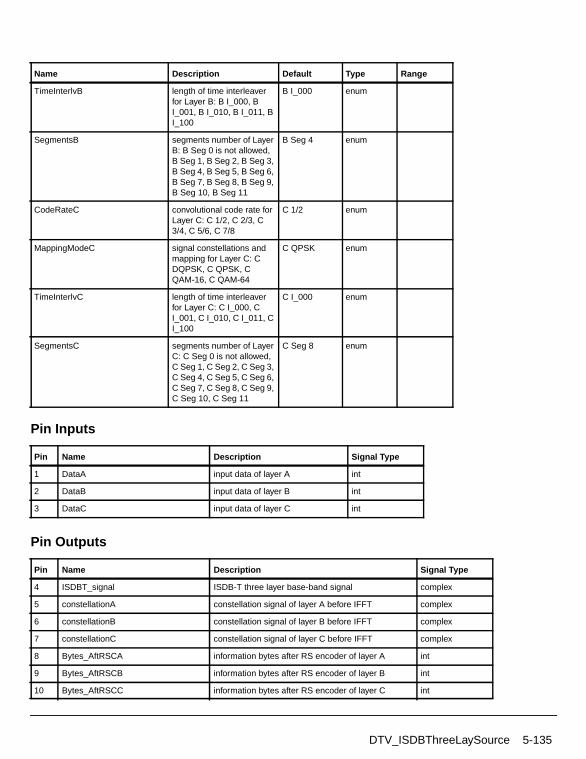
Pin Inputs
Pin Outputs
TimeInterlvB length of time interleaverfor Layer B: B I_000, BI_001, B I_010, B I_011, BI_100
B I_000 enum
SegmentsB segments number of LayerB: B Seg 0 is not allowed,B Seg 1, B Seg 2, B Seg 3,B Seg 4, B Seg 5, B Seg 6,B Seg 7, B Seg 8, B Seg 9,B Seg 10, B Seg 11
B Seg 4 enum
CodeRateC convolutional code rate forLayer C: C 1/2, C 2/3, C3/4, C 5/6, C 7/8
C 1/2 enum
MappingModeC signal constellations andmapping for Layer C: CDQPSK, C QPSK, CQAM-16, C QAM-64
C QPSK enum
TimeInterlvC length of time interleaverfor Layer C: C I_000, CI_001, C I_010, C I_011, CI_100
C I_000 enum
SegmentsC segments number of LayerC: C Seg 0 is not allowed,C Seg 1, C Seg 2, C Seg 3,C Seg 4, C Seg 5, C Seg 6,C Seg 7, C Seg 8, C Seg 9,C Seg 10, C Seg 11
C Seg 8 enum
Pin Name Description Signal Type
1 DataA input data of layer A int
2 DataB input data of layer B int
3 DataC input data of layer C int
Pin Name Description Signal Type
4 ISDBT_signal ISDB-T three layer base-band signal complex
5 constellationA constellation signal of layer A before IFFT complex
6 constellationB constellation signal of layer B before IFFT complex
7 constellationC constellation signal of layer C before IFFT complex
8 Bytes_AftRSCA information bytes after RS encoder of layer A int
9 Bytes_AftRSCB information bytes after RS encoder of layer B int
10 Bytes_AftRSCC information bytes after RS encoder of layer C int
Name Description Default Type Range
DTV_ISDBThreeLaySource 5-135

ISDB-T Components
Notes/Equations
1. This subnetwork model generates a 3-layer ISDB-T baseband signal.
The schematic for this subnetwork is shown in Figure 5-51.
Figure 5-51. DTV_ISDBThreeLaySource Schematic
2. The subnetwork input is a transport stream as defined in MPEG-2 Systems.
The signal format follows ISDB-T transmission specification. Figure 5-52 showsthe ISDB-T baseband system functional block diagram.
5-136 DTV_ISDBThreeLaySource

Figure 5-52. ISDB-T Baseband System Functional Block Diagram
3. Auxiliary information AC1 and AC2 are set to 0 bit (same as CP).
4. Parameter Details
GuardInterval value is 1/32, 1/16, 1/8 or 1/4 (the ratio of guard interval lengthto useful symbol length).
SegmentsA+SegmentsB+SegmentsC=13 is required.
SegmentsB and SegmentsC cannot be 0.
SegmentsA is permanently set to 1.
Time interleaving lengths, based on mode, are listed in Table 5-23.
References
[1]ARIB STD-B31 Version 1.5, Transmission System for Digital TerrestrialTelevision Broadcasting, July 29, 2003.
Table 5-23. Time Interleaving Length
TimeInterlvTime InterleavingLength I (Mode 1)
Time InterleavingLength I (Mode 2)
Time InterleavingLength I (Mode 3)
I_000 0 0 0
I_001 4 2 1
I_010 8 4 2
I_011 16 8 4
I_100 32 16 8
MPEG-2Multiplexer
TSRe-
OuterCode
(204,188)
Division ofTS into
HierarchicalLevels
ByteInterleaving
ConvolutionalCoding
Byte→BitsMSB First
Bits→ByteMSB First
DelayAdjustment
EnergyDispersal
Byte→BitsMSB First
ByteInterleaving
ConvolutionalCoding
Byte→BitsMSB First
Bits→ByteMSB First
DelayAdjustment
EnergyDispersal
Byte→BitsMSB First
ByteInterleaving
ConvolutionalCoding
Byte→BitsMSB First
Bits→ByteMSB First
DelayAdjustment
EnergyDispersal
Byte→BitsMSB First
Multiply
Carrier Modulation
Bit Interleaving Mapping
Carrier Modulation
Bit Interleaving Mapping
Carrier Modulation
Bit Interleaving Mapping
Hierarchical Time FrequencyOFDM
Interleaving Interleaving IFFTGuard
LevelCombining Structure
FrameAdditionInterval
Pilot Signals
TMCC Signal
DTV_ISDBThreeLaySource 5-137

ISDB-T Components
DTV_ISDBThreeLaySource_RF
Description ISDB-T three-layer RF signal sourceLibrary DTV, ISDB-T
Parameters
Name Description Default Unit Type Range
ROut output resistance DefaultROut Ohm real (0, ∞)
RTemp physical temperature, indegrees C
DefaultRTemp Celsius real [-273.15, ∞)
FCarrier carrier frequency 611.0MHz Hz real (0, ∞)
Power modulator output power 40mW W real (0, ∞)
BasicSamplingRate basic sampling rate (2048/252.0)MHz Hz real (0, ∞)
MirrorSpectrum Mirror spectrum aboutcarrier? NO, YES
NO enum
GainImbalance Gain imbalance, Q vs I 0.0 dB real (-∞, ∞)
PhaseImbalance Phase imbalance, Q vs I 0.0 deg real (-∞, ∞)
I_OriginOffset I origin offset (percent) 0.0 real (-∞, ∞)
Q_OriginOffset Q origin offset (percent) 0.0 real (-∞, ∞)
IQ_Rotation IQ rotation 0.0 deg real (-∞, ∞)
Mode transmission mode: Mode1, Mode 2, Mode 3
Mode 1 enum
OversamplingOption oversampling ratio option:Ratio 1, Ratio 2, Ratio 4,Ratio 8, Ratio 16, Ratio 32
Ratio 1 enum
GuardInterval guard interval (fractionalFFT size)
1/32 real [0, 1]
5-138 DTV_ISDBThreeLaySource_RF

CodeRateA convolutional code rate forLayer A: A 1/2, A 2/3, A3/4, A 5/6, A 7/8
A 1/2 enum
MappingModeA signal constellations andmapping for Layer A: ADQPSK, A QPSK, AQAM-16, A QAM-64
A DQPSK enum
TimeInterlvA length of time interleaverfor Layer A: A I_000, AI_001, A I_010, A I_011, AI_100
A I_000 enum
SegmentsA segments number of LayerA: A Seg 0 is not allowed,A Seg 1, A Seg 2, A Seg 3,A Seg 4, A Seg 5, A Seg 6,A Seg 7, A Seg 8, A Seg 9,A Seg 10, A Seg 11
A Seg 1 enum
CodeRateB convolutional code rate forLayer B: B 1/2, B 2/3, B3/4, B 5/6, B 7/8
B 1/2 enum
MappingModeB signal constellations andmapping for Layer B: BDQPSK, B QPSK, BQAM-16, B QAM-64
B DQPSK enum
TimeInterlvB length of time interleaverfor Layer B: B I_000, BI_001, B I_010, B I_011, BI_100
B I_000 enum
SegmentsB segments number of LayerB: B Seg 0 is not allowed,B Seg 1, B Seg 2, B Seg 3,B Seg 4, B Seg 5, B Seg 6,B Seg 7, B Seg 8, B Seg 9,B Seg 10, B Seg 11
B Seg 4 enum
CodeRateC convolutional code rate forLayer C: C 1/2, C 2/3, C3/4, C 5/6, C 7/8
C 1/2 enum
MappingModeC signal constellations andmapping for Layer C: CDQPSK, C QPSK, CQAM-16, C QAM-64
C QPSK enum
TimeInterlvC length of time interleaverfor Layer C: C I_000, CI_001, C I_010, C I_011, CI_100
C I_000 enum
Name Description Default Unit Type Range
DTV_ISDBThreeLaySource_RF 5-139

ISDB-T Components
Pin Outputs
Notes/Equations
1. This subnetwork model generates a 3-layer ISDB-T RF signal source. TheISDB-T baseband signal is fed into the RF modulator. The RF signal is a timedsignal after RF modulation.
The schematic for this subnetwork is shown in Figure 5-53.
2. The format of 3-layer ISDB-T baseband signal source is based on ISDB-Tspecifications; the schematic for DTV_ISDBThreeLaySource is shown inFigure 5-54.
The functional block diagram of the ISDB-T baseband system is shown inFigure 5-55.
SegmentsC segments number of LayerC: C Seg 0 is not allowed,C Seg 1, C Seg 2, C Seg 3,C Seg 4, C Seg 5, C Seg 6,C Seg 7, C Seg 8, C Seg 9,C Seg 10, C Seg 11
C Seg 8 enum
DataType payload data type: PN9,PN15, FIX4, _4_1_4_0,_8_1_8_0, _16_1_16_0,_32_1_32_0, _64_1_64_0
PN9 enum
Pin Name Description Signal Type
1 RF RF signal timed
2 ISDBT_signal ISDB-T two-layer base-band signal complex
3 constellationA constellation signal of layer A before IFFT complex
4 constellationB constellation signal of layer B before IFFT complex
5 constellationC constellation signal of layer C before IFFT complex
6 Bytes_AftRSCA information bytes after RS encoder of layer A int
7 Bytes_UncodedA information bytes before RS encoder of layer A int
8 Bytes_AftRSCB information bytes after RS encoder of layer B int
9 Bytes_UncodedB information bytes before RS encoder of layer B int
10 Bytes_AftRSCC information bytes after RS encoder of layer C int
11 Bytes_UncodedC information bytes before RS encoder of layer C int
Name Description Default Unit Type Range
5-140 DTV_ISDBThreeLaySource_RF

Figure 5-53. DTV_ISDBThreeLaySource_RF Schematic
Figure 5-54. DTV_ISDBThreeLaySource Schematic
DTV_ISDBThreeLaySource_RF 5-141

ISDB-T Components
Figure 5-55. ISDB-T Baseband System Functional Block Diagram
3. Auxiliary information AC1 and AC2 are set to 0 bits (same as CP).
4. Parameter Details
FCarrier defines the RF frequency for the ISDB signal.
Power defines the power level for FCarrier.
BasicSamplingRate specifies the basic sampling rate.
MirrorSpectrum, when set to YES, is used to conjugate the input signal beforeany other processing is done.
GainImbalance, PhaseImbalance, I_OriginOffset, Q_OriginOffset, andIQ_Rotation are used to add certain impairments to the ideal output RF signal.Impairments are added as described here.
The unimpaired RF I and Q envelope voltages have gain and phaseimbalance applied. The RF is given by:
where A is a scaling factor that depends on the Power and ROut parametersspecified by the user, V1(t) is the in-phase RF envelope, V2(t) is thequadrature phase RF envelope, g is the gain imbalance
MPEG-2Multiplexer
TSRe-
OuterCode
(204,188)
Division ofTS into
HierarchicalLevels
ByteInterleaving
ConvolutionalCoding
Byte→BitsMSB First
Bits→ByteMSB First
DelayAdjustment
EnergyDispersal
Byte→BitsMSB First
ByteInterleaving
ConvolutionalCoding
Byte→BitsMSB First
Bits→ByteMSB First
DelayAdjustment
EnergyDispersal
Byte→BitsMSB First
ByteInterleaving
ConvolutionalCoding
Byte→BitsMSB First
Bits→ByteMSB First
DelayAdjustment
EnergyDispersal
Byte→BitsMSB First
Multiply
Carrier Modulation
Bit Interleaving Mapping
Carrier Modulation
Bit Interleaving Mapping
Carrier Modulation
Bit Interleaving Mapping
Hierarchical Time FrequencyOFDM
Interleaving Interleaving IFFTGuard
LevelCombining Structure
FrameAdditionInterval
Pilot Signals
TMCC Signal
V3 t( ) A V1 t( ) ωct( )cos gV2 t( ) ωctφπ180---------+
sin– =
g 10
GainImbalance20
-----------------------------------------------
=
5-142 DTV_ISDBThreeLaySource_RF

and, φ (in degrees) is the phase imbalance.
Next, the signal V3(t) is rotated by IQ_Rotation degrees. I_OriginOffset andQ_OriginOffset are then applied to the rotated signal. Note that the amountsspecified are percentages with respect to the output rms voltage. The outputrms voltage is given by sqrt(2×ROut×Power). Mode is used to selecttransmission mode of 1, 2, or 3 defined in ISDB-T.
OversamplingOption specifies the oversampling ratio of transmission signal.Ratios 1, 2, 4, 8, 16, 32 are supported.
GuardInterval specifies the guard interval (also called cyclic extension) lengthfor each symbol, as a fraction (1/32, 1/16, 1/8, or 1/4) of the FFT time period. Thevalue must match the guard interval length actually used in the input signal inorder for the demodulation to work properly.
CodeRateX (X represents A, B, or C) is defined as code rate of stream. Coderates 1/2, 2/3, 3/4, 5/6 and 7/8 are available.
MappingModeX specifies signal constellation and mapping: DQPSK, QPSK,16QAM, or 64QAM.
TimeInterlvX specifies the time domain interleaver type of the signal: I_000,I_001, I_010, I_011, or I_100. Time interleaving lengths are given in Table 5-24.
SegmentsX specifies the number of segments per layer.SegmentsA+SegmentsB+SegmentsC=13 is required. SegmentsB andSegmentsC cannot be 0. SegmentsA is permanently set to 1.
References
[1]ARIB STD-B31 Version 1.5, Transmission System for Digital TerrestrialTelevision Broadcasting, July 29, 2003.
Table 5-24. Time Interleaving Lengths
TimeInterlvX
Time Interleaving Length
Mode 1 Mode 2 Mode 3
I_000 0 0 0
I_001 4 2 1
I_010 8 4 2
I_011 16 8 4
I_100 32 16 8
DTV_ISDBThreeLaySource_RF 5-143

ISDB-T Components
DTV_ISDBTimeInterlv
Description ISDB-T intra-segment time interleaverLibrary DTV, ISDB-T
Parameters
Pin Inputs
Pin Outputs
Notes/Equations
1. This subnetwork model interleaves modulated symbols in the time domain ofan ISDB-T signal generator.
The schematic for this subnetwork is shown in Figure 5-56.
Name Description Default Type Range
Mode transmission mode: Mode1, Mode 2, Mode 3
Mode 1 enum
MappingMode signal constellations andmapping: DQPSK, QPSK,QAM 16, QAM 64
DQPSK enum
Segments number of segments perlayer
13 int [1, 13]
I time interleaving length:I_000, I_001, I_010, I_011,I_100
I_000 enum
Pin Name Description Signal Type
1 In input symbols to be interleaved complex
Pin Name Description Signal Type
2 Out output symbols after interleaved complex
5-144 DTV_ISDBTimeInterlv

Figure 5-56. DTV_ISDBTimeInterlv Schematic
2. DTV_Delay delays the input complex carrier such that the total number oftransmission and reception delays for each layer is a multiple of frames.
3. Relationships of the I parameter, the number of delay-adjustment symbols, andthe number of delayed frames are given in Table 5-25.
4. The subnetwork works on the basis of OFDM symbols, so the input of thesubnetwork starts with the first data carrier of the corresponding hierarchicallayer.
References
[1]ARIB STD-B31 Version 1.5, Transmission System for Digital TerrestrialTelevision Broadcasting, July 29, 2003.
Table 5-25. Time Interleaving Parameter and Delay Adjustment Values
SubnetworkI ParameterSetting
Mode 1 Mode 2 Mode 3
TimeInterlvI Param.Setting
DelayAdjustmentSymbols
DelayedFrames inTx and Rx
TimeInterlvI Param.Setting
DelayAdjustmentSymbols
DelayedFrames inTx and Rx
TimeInterlvI Param.Setting
DelayAdjustmentSymbols
DelayedFrames inTx and Rx
I_000 0 0 0 0 0 0 0 0 0
I_001 4 28 2 2 14 1 1 109 1
I_010 8 56 4 4 28 2 2 14 1
I_011 16 112 8 8 56 4 4 28 2
I_100 32 224 16 16 112 8 8 56 4
DTV_ISDBTimeInterlv 5-145

ISDB-T Components
DTV_ISDBTwoLayFreqDeinterlv
Description ISDB-T two-layer inter-frequency and intra-frequency deinterleavingLibrary DTV, ISDB-T
Parameters
Pin Inputs
Pin Outputs
Notes/Equations
1. This subnetwork model performs carrier descrambling, carrier rotating, andinter-segment deinterleaving; it is the reverse of the process forDTV_ISDBTwoLayFreqInterlv.
Name Description Default Type Range
Mode transmission mode: Mode1, Mode 2, Mode 3
Mode 1 enum
MappingModeA signal constellations andmapping of layer A: ADQPSK, A QPSK, AQAM-16, A QAM-64
A DQPSK enum
SegmentsA segment number of layer A 5 int [1, 13]
MappingModeB signal constellations andmapping of layer B: BDQPSK, B QPSK, BQAM-16, B QAM-64
B QAM-64 enum
SegmentsB segment number of layer B 8 int [1, 13]
Pin Name Description Signal Type
1 In1 input anytype
2 In2 input anytype
Pin Name Description Signal Type
3 Out1 output anytype
4 Out2 output anytype
5-146 DTV_ISDBTwoLayFreqDeinterlv

The schematic for this subnetwork is shown in Figure 5-57.
Figure 5-57. DTV_ISDBTwoLayFreqDeinterlv Schematic
2. Inter-segment deinterleaving must be conducted on two or more data segmentswhen they belong to the same type of modulated portion, even if theirhierarchical levels differ.
References
[1]ARIB STD-B31 Version 1.5, Transmission System for Digital TerrestrialTelevision Broadcasting, July 29, 2003.
DTV_ISDBTwoLayFreqDeinterlv 5-147

ISDB-T Components
DTV_ISDBTwoLayFreqInterlv
Description ISDB-T two-layer inter-frequency and intra-frequency interleavingLibrary DTV, ISDB-T
Parameters
Pin Inputs
Pin Outputs
Notes/Equations
1. This subnetwork model performs frequency interleaving for ISDB-T 2-layerhierarchical transmission.
Name Description Default Type Range
Mode transmission mode: Mode1, Mode 2, Mode 3
Mode 1 enum
MappingModeA signal constellations andmapping of layer A: ADQPSK, A QPSK, AQAM-16, A QAM-64
A DQPSK enum
SegmentsA segment number of layer A 5 int [1, 13]
MappingModeB signal constellations andmapping of layer B: BDQPSK, B QPSK, BQAM-16, B QAM-64
B QAM-64 enum
SegmentsB segment number of layer B 8 int [1, 13]
Pin Name Description Signal Type
1 In1 input anytype
2 In2 input anytype
Pin Name Description Signal Type
3 Out1 output anytype
4 Out2 output anytype
5-148 DTV_ISDBTwoLayFreqInterlv

The schematic for this subnetwork is shown in Figure 5-58.
Figure 5-58. DTV_ISDBTwoLayFreqInterlv Schematic
2. Inter-segment interleaving must be conducted on two or more data segmentswhen they belong to the same type of modulated portion, even if theirhierarchical levels differ.
References
[1]ARIB STD-B31 Version 1.5, Transmission System for Digital TerrestrialTelevision Broadcasting, July 29, 2003.
DTV_ISDBTwoLayFreqInterlv 5-149

ISDB-T Components
DTV_ISDBTwoLayReceiver
Description ISDB-T two-layer receiverLibrary DTV, ISDB-T
Parameters
Name Description Default Type Range
Mode transmission mode: Mode1, Mode 2, Mode 3
Mode 1 enum
OversamplingOption oversampling ratio option:Ratio 1, Ratio 2, Ratio 4,Ratio 8, Ratio 16, Ratio 32
Ratio 1 enum
GuardInterval guard interval (fractionalFFT size)
1/32 real [0, 1]
CodeRateA convolutional code rate forLayer A: A 1/2, A 2/3, A3/4, A 5/6, A 7/8
A 1/2 enum
MappingModeA signal constellations andmapping for Layer A: ADQPSK, A QPSK, AQAM-16, A QAM-64
A DQPSK enum
TimeInterlvA length of time interleaverfor Layer A: A I_000, AI_001, A I_010, A I_011, AI_100
A I_000 enum
TrunLenA path memory truncationlength of Viterbi decodingalgorithm, in bytes
10 int [5, ∞)
SegmentsA segments number of LayerA: A Seg 0 is not allowed,A Seg 1, A Seg 2, A Seg 3,A Seg 4, A Seg 5, A Seg 6,A Seg 7, A Seg 8, A Seg 9,A Seg 10, A Seg 11, A Seg12
A Seg 5 enum
CodeRateB convolutional code rate forLayer B: B 1/2, B 2/3, B3/4, B 5/6, B 7/8
B 7/8 enum
5-150 DTV_ISDBTwoLayReceiver

Pin Inputs
Pin Outputs
Notes/Equations
1. This 2-layer ISDB-T baseband receiver subnetwork performs 2-layer OFDMdemodulation, frequency deinterleaving, time deinterleaving, demapping and
MappingModeB signal constellations andmapping for Layer B: BDQPSK, B QPSK, BQAM-16, B QAM-64
B QAM-64 enum
TimeInterlvB length of time interleaverfor Layer B: B I_000, BI_001, B I_010, B I_011, BI_100
B I_000 enum
TrunLenB path memory truncationlength of Viterbi decodingalgorithm, in bytes
10 int [5, ∞)
SegmentsB segments number of LayerB: B Seg 0 is not allowed,B Seg 1, B Seg 2, B Seg 3,B Seg 4, B Seg 5, B Seg 6,B Seg 7, B Seg 8, B Seg 9,B Seg 10, B Seg 11, B Seg12
B Seg 8 enum
Pin Name Description Signal Type
1 Rx_signal received signal to be demodulated complex
Pin Name Description Signal Type
2 constellationA constellation signal after OFDM demodulation oflayer A
complex
3 constellationB constellation signal after OFDM demodulation oflayer B
complex
4 Bytes_BefRSDA decoded bytes after Viterbi decoder andde-randomizer of layer A
int
5 Bytes_DecodedA decoded bytes after Reed Solomon decoder of layerA
int
6 Bytes_BefRSDB decoded bytes after Viterbi decoder andde-randomizer of layer B
int
7 Bytes_DecodedB decoded bytes after Reed Solomon decoder of layerB
int
Name Description Default Type Range
DTV_ISDBTwoLayReceiver 5-151

ISDB-T Components
bit-wise deinterleaving, inner decoding (Viterbi), byte-wise deinterleaving,derandomizing and Reed-Solomon decoding.
The schematic for this subnetwork is shown in Figure 5-59.
Figure 5-59. DTV_ISDBTwoLayReceiver Schematic
2. The input signal starts with the first symbol of an ISDB-T signal frame.
3. Parameter Details
Mode specifies transmission mode 2K (Mode 1), 4K (Mode 2), or 8K (Mode 3)defined in ISDB-T.
OversamplingOption specifies the oversampling ratio of transmission signal.Ratios 1, 2, 4, 8, 16, and 32 are supported in this model. For example, if Ratio 2is selected, FFT size of the demodulator will double; if Ratio 1 is selected nooversampling will be performed.
GuardInterval specifies the guard interval (also called cyclic extension) lengthfor each symbol, as a fraction (1/32, 1/16, 1/8, or 1/4) of the FFT time period. Thevalue must match the guard interval length actually used in the input signal inorder for the demodulation to work properly.
CodeRateX (X represents A or B) specifies the inner code rate 1/2, 2/3, 3/4, 5/6,or 7/8.
MappingModeX specifies signal constellation and mapping for DQPSK, QPSK,16QAM or 64QAM.
5-152 DTV_ISDBTwoLayReceiver

TimeInterlvX is time domain interleaver type of the signal: I_000, I_001, I_010,I_011, or I_100.
SegmentsX specifies the number of segments used for each layer.SegmentsA+SegmentsB=13 is required. SegmentsB cannot be 0.
TrunLenX is the truncation length (1×8 bits, 2×8 bits), in bytes, in the Viterbidecoding algorithm.
4. Output Delays
DTV_ISDBChDecoder consists of Viterbi decoder, byte-wise deinterleaver andderandomizer. Viterbi decoder introduces different delay for different pathmemory truncation length (TrunLen parameter). For BER measurementsynchronization, the delay between byte interleaver and deinterleaver must beadjusted to a multiple of 12 bytes, and the delay between randomizer andderandomizer must be adjusted to a multiple of 204 bytes. Here, both delays areadjusted to a multiple of 204 bytes.
The basic delay calculation of an ISDB-T receiver is shown in Figure 5-60;delays for layers A and B are each calculated with their own hierarchicalparameters. Assuming MapRate=2, 2, 4, 6, CodeRateFrac=1/2, 2/3, 3/4, 5/6,7/8, then MapRate[MappingMode+1] represents the bit number mapped ontoone data carrier, and CodeRateFrac[CodeRate+1] represents the inner coderrate; we get:
Figure 5-60. ISDB-T Receiver Delay Calculation
DTV_ISDBTwoLayReceiver 5-153

ISDB-T Components
where
D_OFDMMod*108/96 is the delay between the Constellation pins ofDTV_ISDBTwoLaySource and DTV_ISDBTwoLayReceiver.
D_AfterDerandomize is the delay between pins Bytes_AftRSC inDTV_ISDBTwoLaySource and Bytes_BefRSD in DTV_ISDBTwoLayReceiver.
D_AfterRSDecoder is the delay between pins Bytes_Uncoded inDTV_ISDBTwoLaySource and Bytes_Decoded in DTV_ISDBTwoLayReceiver.
When connecting the receiver to the signal source in MER and BERmeasurements, the reference signal from the signal generator must be delayedaccording to the basic formula in Figure 5-60.
References
[1]ARIB STD-B31 Version 1.5, Transmission System for Digital TerrestrialTelevision Broadcasting, July 29, 2003.
5-154 DTV_ISDBTwoLayReceiver

DTV_ISDBTwoLayReceiver_RF
Description ISDB-T two-layer RF receiverLibrary DTV, ISDB-T
Parameters
Name Description Default Unit Type Range
RIn input resistance DefaultRIn Ohm real (0, ∞)
RTemp physical temperature, indegrees C
DefaultRTemp Celsius real [-273.15, ∞)
GainImbalance Gain imbalance, Q vs I 0.0 dB real (-∞, ∞)
PhaseImbalance Phase imbalance, Q vs I 0.0 deg real (-∞, ∞)
FCarrier carrier frequency 611.0MHz Hz real (0, ∞)
Sensitivity voltage output sensitivity,Vout/Vin
1 real (-∞, ∞)
Phase reference phase in degrees 0.0 deg real (-∞, ∞)
Mode transmission mode: Mode1, Mode 2, Mode 3
Mode 1 enum
OversamplingOption oversampling ratio option:Ratio 1, Ratio 2, Ratio 4,Ratio 8, Ratio 16, Ratio 32
Ratio 1 enum
GuardInterval guard interval (fractionalFFT size)
1/32 real [0, 1]
MappingModeA signal constellations andmapping for Layer A: ADQPSK, A QPSK, AQAM-16, A QAM-64
A DQPSK enum
CodeRateA convolutional code rate forLayer A: A 1/2, A 2/3, A3/4, A 5/6, A 7/8
A 1/2 enum
TimeInterlvA length of time interleaverfor Layer A: A I_000, AI_001, A I_010, A I_011, AI_100
A I_000 enum
DTV_ISDBTwoLayReceiver_RF 5-155

ISDB-T Components
Pin Inputs
Pin Outputs
TrunLenA path memory truncationlength of Viterbi decodingalgorithm, in bytes
10 int [5, ∞)
SegmentsA segments number of LayerA: A Seg 0 is not allowed,A Seg 1, A Seg 2, A Seg 3,A Seg 4, A Seg 5, A Seg 6,A Seg 7, A Seg 8, A Seg 9,A Seg 10, A Seg 11, A Seg12
A Seg 5 enum
MappingModeB signal constellations andmapping for Layer B: BDQPSK, B QPSK, BQAM-16, B QAM-64
B QAM-64 enum
CodeRateB convolutional code rate forLayer B: B 1/2, B 2/3, B3/4, B 5/6, B 7/8
B 7/8 enum
TimeInterlvB length of time interleaverfor Layer B: B I_000, BI_001, B I_010, B I_011, BI_100
B I_000 enum
TrunLenB path memory truncationlength of Viterbi decodingalgorithm, in bytes
10 int [5, ∞)
SegmentsB segments number of LayerB: B Seg 0 is not allowed,B Seg 1, B Seg 2, B Seg 3,B Seg 4, B Seg 5, B Seg 6,B Seg 7, B Seg 8, B Seg 9,B Seg 10, B Seg 11, B Seg12
B Seg 8 enum
Pin Name Description Signal Type
1 RF received OFDM signal to be demodulated timed
Pin Name Description Signal Type
2 constellationA constellation signal after OFDM demodulation oflayer A
complex
3 constellationB constellation signal after OFDM demodulation oflayer B
complex
4 Bytes_BefRSDA decoded bytes after Viterbi decoder andde-randomizer of layer A
int
5 Bytes_DecodedA decoded bytes after Reed Solomon decoder of layerA
int
Name Description Default Unit Type Range
5-156 DTV_ISDBTwoLayReceiver_RF

Notes/Equations
1. This subnetwork model is a 2-layer ISDB-T RF receiver.
The schematic for this subnetwork is shown in Figure 5-61.
Figure 5-61. DTV_ISDBTwoLayReceiver_RF Schematic
2. The input timed signal is demodulated from RF to baseband and fed to theISDB-T 2-layer baseband receiver.
3. The input signal starts with the first symbol of an ISDB-T signal frame.
4. The baseband receiver (DTV_ISDBTwoLayReceiver) schematic is shown inFigure 5-62.
6 Bytes_BefRSDB decoded bytes after Viterbi decoder andde-randomizer of layer B
int
7 Bytes_DecodedB decoded bytes after Reed Solomon decoder of layerB
int
Pin Name Description Signal Type
DTV_ISDBTwoLayReceiver_RF 5-157

ISDB-T Components
Figure 5-62. DTV_ISDBTwoLayReceiver Schematic
5. Baseband Parameter Details
Mode specifies transmission mode 2K (Mode 1), 4K (Mode 2), or 8K (Mode 3)defined in ISDB-T.
OversamplingOption specifies the oversampling ratio of transmission signal.Ratios 1, 2, 4, 8, 16, and 32 are supported in this model. For example, if Ratio 2is selected, FFT size of the demodulator will double; if Ratio 1 is selected nooversampling will be performed.
GuardInterval specifies the guard interval (also called cyclic extension) lengthfor each symbol, as a fraction (1/32, 1/16, 1/8, or 1/4) of the FFT time period. Thevalue must match the guard interval length actually used in the input signal inorder for the demodulation to work properly.
CodeRateX (X represents A or B) specifies the inner code rate 1/2, 2/3, 3/4, 5/6,or 7/8.
MappingModeX specifies signal constellation and mapping for DQPSK, QPSK,16QAM, or 64QAM.
TimeInterlvX specifies the time domain interleaver type of the signal: I_000,I_001, I_010, I_011, or I_100.
SegmentsX specifies the number of segments used for each layer.SegmentsA+SegmentsB=13 is required. SegmentsB cannot be 0.
5-158 DTV_ISDBTwoLayReceiver_RF

TrunLenX specifies the truncation length (1×8 bits, 2×8 bits), in bytes, in theViterbi decoding algorithm.
6. Output Delays
DTV_ISDBChDecoder consists of Viterbi decoder, byte-wise deinterleaver andderandomizer. Viterbi decoder introduces different delay for different pathmemory truncation length (parameter TrunLen). For BER measurement, delaysynchronization between byte-interleaver and byte deinterleaver is adjusted toa multiple of 12 bytes and the delay between randomizer and derandomizer isadjusted to a multiple of 204 bytes. Here, both delays are adjusted to a multipleof 204 bytes.
The basic delay calculation of an ISDB-T receiver is shown in Figure 5-63.Delays for layers A and B are each calculated with their own hierarchicalparameters. Assuming MapRate=2, 2, 4, 6, CodeRateFrac=1/2, 2/3, 3/4, 5/6,7/8, then MapRate[MappingMode+1] represents the bit number mapped ontoone data carrier, and CodeRateFrac[CodeRate+1] represents the inner coderrate, we get:
Figure 5-63. Delay Calculation of an ISDB-T Receiver
where
D_OFDMMod*108/96 is the delay between the Constellation pins inDTV_ISDBTwoLaySource DTV_ISDBTwoLayReceiver.
D_AfterDerandomize is the delay between Bytes_AftRSC inDTV_ISDBTwoLaySource and Bytes_BefRSD in DTV_ISDBTwoLayReceiver.
D_AfterRSDecoder is the delay between pin Bytes_Uncoded inDTV_ISDBTwoLaySource and Bytes_Decoded in DTV_ISDBTwoLayReceiver.
DTV_ISDBTwoLayReceiver_RF 5-159
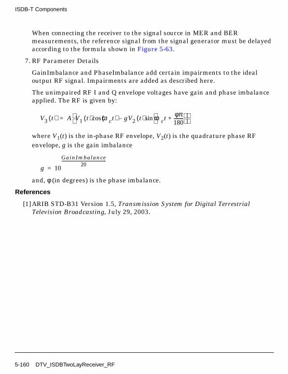
ISDB-T Components
When connecting the receiver to the signal source in MER and BERmeasurements, the reference signal from the signal generator must be delayedaccording to the formula shown in Figure 5-63.
7. RF Parameter Details
GainImbalance and PhaseImbalance add certain impairments to the idealoutput RF signal. Impairments are added as described here.
The unimpaired RF I and Q envelope voltages have gain and phase imbalanceapplied. The RF is given by:
where V1(t) is the in-phase RF envelope, V2(t) is the quadrature phase RFenvelope, g is the gain imbalance
and, φ (in degrees) is the phase imbalance.
References
[1]ARIB STD-B31 Version 1.5, Transmission System for Digital TerrestrialTelevision Broadcasting, July 29, 2003.
V3 t( ) A V1 t( ) ωct( )cos gV2 t( ) ωct φπ180---------+
sin– =
g 10
GainImbalance20
-----------------------------------------------=
5-160 DTV_ISDBTwoLayReceiver_RF

DTV_ISDBTwoLaySource
Description ISDB-T two-layer signal sourceLibrary DTV, ISDB-T
Parameters
Name Description Default Type Range
Mode transmission mode: Mode1, Mode 2, Mode 3
Mode 1 enum
OversamplingOption oversampling ratio option:Ratio 1, Ratio 2, Ratio 4,Ratio 8, Ratio 16, Ratio 32
Ratio 1 enum
GuardInterval guard interval (fractionalFFT size)
1/32 real [0, 1]
CodeRateA convolutional code rate forLayer A: A 1/2, A 2/3, A3/4, A 5/6, A 7/8
A 1/2 enum
MappingModeA signal constellations andmapping for Layer A: ADQPSK, A QPSK, AQAM-16, A QAM-64
A DQPSK enum
TimeInterlvA length of time interleaverfor Layer A: A I_000, AI_001, A I_010, A I_011, AI_100
A I_000 enum
SegmentsA segments number of LayerA: A Seg 0 is not allowed,A Seg 1, A Seg 2, A Seg 3,A Seg 4, A Seg 5, A Seg 6,A Seg 7, A Seg 8, A Seg 9,A Seg 10, A Seg 11, A Seg12
A Seg 5 enum
CodeRateB convolutional code rate forLayer B: B 1/2, B 2/3, B3/4, B 5/6, B 7/8
B 7/8 enum
MappingModeB signal constellations andmapping for Layer B: BDQPSK, B QPSK, BQAM-16, B QAM-64
B QAM-64 enum
DTV_ISDBTwoLaySource 5-161
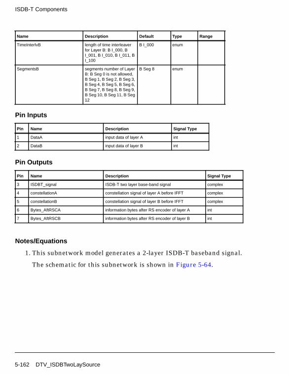
ISDB-T Components
Pin Inputs
Pin Outputs
Notes/Equations
1. This subnetwork model generates a 2-layer ISDB-T baseband signal.
The schematic for this subnetwork is shown in Figure 5-64.
TimeInterlvB length of time interleaverfor Layer B: B I_000, BI_001, B I_010, B I_011, BI_100
B I_000 enum
SegmentsB segments number of LayerB: B Seg 0 is not allowed,B Seg 1, B Seg 2, B Seg 3,B Seg 4, B Seg 5, B Seg 6,B Seg 7, B Seg 8, B Seg 9,B Seg 10, B Seg 11, B Seg12
B Seg 8 enum
Pin Name Description Signal Type
1 DataA input data of layer A int
2 DataB input data of layer B int
Pin Name Description Signal Type
3 ISDBT_signal ISDB-T two layer base-band signal complex
4 constellationA constellation signal of layer A before IFFT complex
5 constellationB constellation signal of layer B before IFFT complex
6 Bytes_AftRSCA information bytes after RS encoder of layer A int
7 Bytes_AftRSCB information bytes after RS encoder of layer B int
Name Description Default Type Range
5-162 DTV_ISDBTwoLaySource

Figure 5-64. DTV_ISDBTwoLaySource Schematic
2. Input to the subnetwork is a transport stream defined in MPEG-2 Systems.
The signal format follows the ISDB-T transmission specification. Figure 5-65shows functional block diagram of the ISDB-T baseband system.
Figure 5-65. ISDB-T Baseband System Functional Block Diagram
MPEG-2Multiplexer
TSRe-
OuterCode
(204,188)
Division ofTS into
HierarchicalLevels
ByteInterleaving
ConvolutionalCoding
Byte→BitsMSB First
Bits→ByteMSB First
DelayAdjustment
EnergyDispersal
Byte→BitsMSB First
ByteInterleaving
ConvolutionalCoding
Byte→BitsMSB First
Bits→ByteMSB First
DelayAdjustment
EnergyDispersal
Byte→BitsMSB First
ByteInterleaving
ConvolutionalCoding
Byte→BitsMSB First
Bits→ByteMSB First
DelayAdjustment
EnergyDispersal
Byte→BitsMSB First
Multiply
Carrier Modulation
Bit Interleaving Mapping
Carrier Modulation
Bit Interleaving Mapping
Carrier Modulation
Bit Interleaving Mapping
Hierarchical Time FrequencyOFDM
Interleaving Interleaving IFFTGuard
LevelCombining Structure
FrameAdditionInterval
Pilot Signals
TMCC Signal
DTV_ISDBTwoLaySource 5-163

ISDB-T Components
3. Auxiliary information AC1 and AC2 are set to bit 0 (same as CP).
4. Parameter Details
SegmentsA+SegmentsB=13 is required.
SegmentsB cannot be 0.
Time interleaving lengths, based on mode, are listed in Table 5-26.
GuardInterval value is 1/32, 1/16, 1/8 or 1/4 (the ratio of guard interval lengthto useful symbol length).
References
[1]ARIB STD-B31 Version 1.5, Transmission System for Digital TerrestrialTelevision Broadcasting, July 29, 2003.
Table 5-26. Time Interleaving Length
TimeInterlvTime InterleavingLength I (Mode 1)
Time InterleavingLength I (Mode 2)
Time InterleavingLength I (Mode 3)
I_000 0 0 0
I_001 4 2 1
I_010 8 4 2
I_011 16 8 4
I_100 32 16 8
5-164 DTV_ISDBTwoLaySource

DTV_ISDBTwoLaySource_RF
Description ISDB-T two-layer RF signal sourceLibrary DTV, ISDB-T
Parameters
Name Description Default Unit Type Range
ROut output resistance DefaultROut Ohm real (0, ∞)
RTemp physical temperature, indegrees C
DefaultRTemp Celsius real [-273.15, ∞)
FCarrier carrier frequency 611.0MHz Hz real (0, ∞)
Power modulator output power 40mW W real (0, ∞)
BasicSamplingRate basic sampling rate (2048/252.0)MHz Hz real (0, ∞)
MirrorSpectrum Mirror spectrum aboutcarrier? NO, YES
NO enum
GainImbalance Gain imbalance, Q vs I 0.0 dB real (-∞, ∞)
PhaseImbalance Phase imbalance, Q vs I 0.0 deg real (-∞, ∞)
I_OriginOffset I origin offset (percent) 0.0 real (-∞, ∞)
Q_OriginOffset Q origin offset (percent) 0.0 real (-∞, ∞)
IQ_Rotation IQ rotation 0.0 deg real (-∞, ∞)
Mode transmission mode: Mode1, Mode 2, Mode 3
Mode 1 enum
OversamplingOption oversampling ratio option:Ratio 1, Ratio 2, Ratio 4,Ratio 8, Ratio 16, Ratio 32
Ratio 1 enum
GuardInterval guard interval (fractionalFFT size)
1/32 real [0, 1]
CodeRateA convolutional code rate forLayer A: A 1/2, A 2/3, A3/4, A 5/6, A 7/8
A 1/2 enum
DTV_ISDBTwoLaySource_RF 5-165
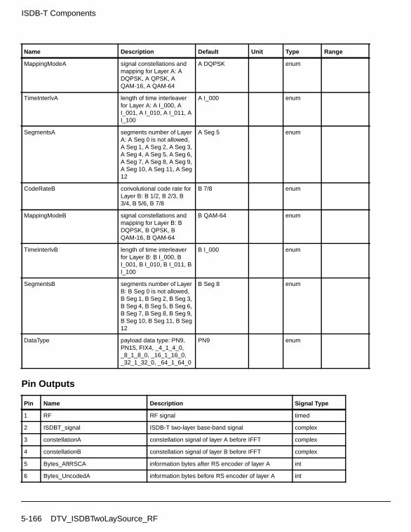
ISDB-T Components
Pin Outputs
MappingModeA signal constellations andmapping for Layer A: ADQPSK, A QPSK, AQAM-16, A QAM-64
A DQPSK enum
TimeInterlvA length of time interleaverfor Layer A: A I_000, AI_001, A I_010, A I_011, AI_100
A I_000 enum
SegmentsA segments number of LayerA: A Seg 0 is not allowed,A Seg 1, A Seg 2, A Seg 3,A Seg 4, A Seg 5, A Seg 6,A Seg 7, A Seg 8, A Seg 9,A Seg 10, A Seg 11, A Seg12
A Seg 5 enum
CodeRateB convolutional code rate forLayer B: B 1/2, B 2/3, B3/4, B 5/6, B 7/8
B 7/8 enum
MappingModeB signal constellations andmapping for Layer B: BDQPSK, B QPSK, BQAM-16, B QAM-64
B QAM-64 enum
TimeInterlvB length of time interleaverfor Layer B: B I_000, BI_001, B I_010, B I_011, BI_100
B I_000 enum
SegmentsB segments number of LayerB: B Seg 0 is not allowed,B Seg 1, B Seg 2, B Seg 3,B Seg 4, B Seg 5, B Seg 6,B Seg 7, B Seg 8, B Seg 9,B Seg 10, B Seg 11, B Seg12
B Seg 8 enum
DataType payload data type: PN9,PN15, FIX4, _4_1_4_0,_8_1_8_0, _16_1_16_0,_32_1_32_0, _64_1_64_0
PN9 enum
Pin Name Description Signal Type
1 RF RF signal timed
2 ISDBT_signal ISDB-T two-layer base-band signal complex
3 constellationA constellation signal of layer A before IFFT complex
4 constellationB constellation signal of layer B before IFFT complex
5 Bytes_AftRSCA information bytes after RS encoder of layer A int
6 Bytes_UncodedA information bytes before RS encoder of layer A int
Name Description Default Unit Type Range
5-166 DTV_ISDBTwoLaySource_RF

Notes/Equations
1. This subnetwork model generates a 2-layer ISDB-T RF source signal. Thebaseband signal of ISDB-T is fed into the RF modulator. RF signal is timedsignal after RF modulation.
The schematic for this subnetwork is shown in Figure 5-66.
Figure 5-66. DTV_ISDBTwoLaySource_RF Schematic
2. The 2-layer ISDB-T baseband signal source format is based on ISDB-Tspecifications. The schematic for DTV_ISDBTwoLaySource is shown inFigure 5-67.
3. The ISDB-T baseband system functional block diagram is shown in Figure 5-68.
7 Bytes_AftRSCB information bytes after RS encoder of layer B int
8 Bytes_UncodedB information bytes before RS encoder of layer B int
Pin Name Description Signal Type
DTV_ISDBTwoLaySource_RF 5-167

ISDB-T Components
Figure 5-67. DTV_ISDBTwoLaySource Schematic
Figure 5-68. Baseband System Functional Block Diagram
4. Herein auxiliary information AC1 and AC2 are set to 0 bits (same as CP).
MPEG-2Multiplexer
TSRe-
OuterCode
(204,188)
Division ofTS into
HierarchicalLevels
ByteInterleaving
ConvolutionalCoding
Byte→BitsMSB First
Bits→ByteMSB First
DelayAdjustment
EnergyDispersal
Byte→BitsMSB First
ByteInterleaving
ConvolutionalCoding
Byte→BitsMSB First
Bits→ByteMSB First
DelayAdjustment
EnergyDispersal
Byte→BitsMSB First
ByteInterleaving
ConvolutionalCoding
Byte→BitsMSB First
Bits→ByteMSB First
DelayAdjustment
EnergyDispersal
Byte→BitsMSB First
Multiply
Carrier Modulation
Bit Interleaving Mapping
Carrier Modulation
Bit Interleaving Mapping
Carrier Modulation
Bit Interleaving Mapping
Hierarchical Time FrequencyOFDM
Interleaving Interleaving IFFTGuard
LevelCombining Structure
FrameAdditionInterval
Pilot Signals
TMCC Signal
5-168 DTV_ISDBTwoLaySource_RF

5. Parameter Details
FCarrier defines the RF frequency for the ISDB signal.
Power defines the power level for FCarrier.
BasicSamplingRate specifies the basic sampling rate.
The MirrorSpectrum is used to conjugate the input signal (when set to YES)before any other processing is done.
The GainImbalance, PhaseImbalance, I_OriginOffset, Q_OriginOffset, andIQ_Rotation parameters are used to add certain impairments to the idealoutput RF signal. Impairments are added as described here.
The unimpaired RF I and Q envelope voltages have gain and phaseimbalance applied. The RF is given by:
where A is a scaling factor that depends on the Power and ROut parametersspecified by the user, V1(t) is the in-phase RF envelope, V2(t) is thequadrature phase RF envelope, g is the gain imbalance
and, φ (in degrees) is the phase imbalance.
Next, the signal V3(t) is rotated by IQ_Rotation degrees. I_OriginOffset andQ_OriginOffset are then applied to the rotated signal. Note that the amountsspecified are percentages with respect to the output rms voltage. The outputrms voltage is given by sqrt(2×ROut×Power). Mode is used to selecttransmission mode of 1, 2, or 3 defined in ISDB-T.
OversamplingOption specifies the oversampling ratio of transmission signal.Oversampling ratios 1, 2, 4, 8, 16, 32 are supported in this source.
GuardInterval specifies the guard interval (also called cyclic extension) lengthfor each symbol, as a fraction (1/32, 1/16, 1/8, or 1/4) of the FFT time period. Thevalue must match the guard interval length actually used in the input signal inorder for the demodulation to work properly.
CodeRateX (where X represents A or B) specifies the inner code rate 1/2, 2/3,3/4, 5/6, or 7/8.
V3 t( ) A V1 t( ) ωct( )cos gV2 t( ) ωctφπ180---------+
sin– =
g 10
GainImbalance20
-----------------------------------------------
=
DTV_ISDBTwoLaySource_RF 5-169

ISDB-T Components
MappingModeX specifies signal constellation and mapping for DQPSK, QPSK,16QAM, or 64QAM.
Time interleaving lengths are given in Table 5-27.
SegmentsX specifies the number of segments. SegmentsA+SegmentsB=13 isrequired. SegmentsB cannot be 0.
References
[1]ARIB STD-B31 Version 1.5, Transmission System for Digital TerrestrialTelevision Broadcasting, July 29, 2003.
Table 5-27. Time Interleaving Lengths
TimeInterlv
Time Interleaving Length
Mode 1 Mode 2 Mode 3
I_000 0 0 0
I_001 4 2 1
I_010 8 4 2
I_011 16 8 4
I_100 32 16 8
5-170 DTV_ISDBTwoLaySource_RF

DTV_PackTMCC
Description Complete TMCC bits (204 bits)Library DTV, ISDB-TClass SDFDTV_PackTMCC
Parameters
Pin Inputs
Pin Outputs
Notes/Equations
1. The model is used to multiplex the CDSC coded TMCC information bits (184bits) and other no-coded 20 bits, which include initialization bit,synchronization of TMCC and system type.
Name Description Default Type Range
Length length of TMCCtransmission format
204 int 204
InformLength length of TMCCinformation after CDSC
184 int 184
InitiBit initialization bit for theDBPSK modulation (1 bit)
1 int 0, 1
SynchWord synchronization word (16bits): W0, W1
W0 enum
SegDesc segment descriptor (3 bits):Differential, Coherent
Differential enum
Pin Name Description Signal Type
1 input TMCC information bits after CDSC coding int
Pin Name Description Signal Type
2 output complete TMCC transmission format int
DTV_PackTMCC 5-171

ISDB-T Components
According to ISDB-T, the first bit B0 is the initialization bit for DBPSKmodulation; B0 to B16 is a 16-bit synchronization sequence that takes w0 and w1(the inverse of w0) in turn in every frame; B17 to B19 represent the segmentdescriptor (differential modulation 111, coherent modulation 000); B20 to B203include TMCC 102 information bits and 82-bit parity (these 184 bits are CDSCcoded).
References
[1]ARIB-JAPAN, Terrestrial Integrated Services Digital Broadcasting (ISDB-T);Specification of Channel Coding, Framing Structure and Modulation,Sept.1998.
5-172 DTV_PackTMCC

DTV_TMCCDemod
Description TMCC differential demodulationLibrary DTV, ISDB-TClass SDFDTV_TMCCDemod
Parameters
Pin Inputs
Pin Outputs
Notes/Equations
1. The model performs DBPSK demodulation for 204 complex signals about thereceived TMCC format signal.
Based on the received signal, this model makes hard decision on the real part ofthe complex signal.
Name Description Default Type Range
Length length of TMCC bits perOFDM frame
204 int 204
Pin Name Description Signal Type
1 input TMCC format (204 bits) before demodulation in thereceiver
complex
Pin Name Description Signal Type
2 output demodulated TMCC transmission format int
B′ i[ ] 0= if Re x i[ ] 0>
B′ i[ ] 1= if Re x i[ ] 0<
DTV_TMCCDemod 5-173

ISDB-T Components
where 0 ≤ i < 204. Then set B0 = B′ 0], the DBPSK demodulation as follows:
Bi = B [i] ⊕ B′ [i - 1]
where i=1,2, ... , 203.
References
[1]ARIB-JAPAN, Terrestrial Integrated Services Digital Broadcasting (ISDB-T);Specification of Channel Coding, Framing Structure and Modulation,Sept.1998.
5-174 DTV_TMCCDemod

DTV_TMCCInfo
Description TMCC information for 102 bits from b20 to b121 in TMCC bitassignmentLibrary DTV, ISDB-TClass SDFDTV_TMCCInfo
Parameters
Name Description Default Type Range
Length length of TMCCinformation bits
102 int 102
Description system description (2 bits):ISDB-T, Reserved Des 1,Reserved Des 2, ReservedDes 3
ISDB-T enum
Count index for transmissionparameter change (4 bits):Ordinary, Frames 15,Frames 14, Frames 13,Frames 12, Frames 11,Frames 10, Frames 9,Frames 8, Frames 7,Frames 6, Frames 5,Frames 4, Frames 3,Frames 2, Frames 1
Ordinary enum
Flag control flag for alertbroadcasting (1 bit):Ordinary Control,Switch-on
Ordinary Control enum
CurFlag current partial receptionlayer (1 bit): Unused CurFlag, Used Cur Flag
Used Cur Flag enum
CurA_Mod current modulation forLayer A (3 bits): CurADQPSK, CurA QPSK,CurA 16QAM, CurA64QAM, CurA ReservedMod 1, CurA ReservedMod 2, CurA ReservedMod 3, CurA Unused LayerMod
CurA DQPSK enum
DTV_TMCCInfo 5-175

ISDB-T Components
CurA_Rate current code rate for LayerA ( 3 bits): CurA 1/2, CurA2/3, CurA 3/4, CurA 5/6,CurA 7/8, CurA ReservedCod 1, CurA ReservedCod 2, CurA Unused LayerCod
CurA 1/2 enum
CurA_Interlv current time interleaver forLayer A (3 bits): CurA Int 00 0, CurA Int 4 2 1, CurAInt 8 4 2, CurA Int 16 8 4,CurA Int 32 16 8, CurAReserved Int 1, CurAReserved Int 2, CurAUnused Layer Int
CurA Int 8 4 2 enum
CurA_NumSeg current number ofsegments for Layer A (4bits): CurA Reserved Seg1, CurA Seg 1, CurA Seg2, CurA Seg 3, CurA Seg4, CurA Seg 5, CurA Seg6, CurA Seg 7, CurA Seg8, CurA Seg 9, CurA Seg10, CurA Seg 11, CurASeg 12, CurA Seg 13,CurA Reserved Seg 2,CurA Unused Layer Seg
CurA Seg 13 enum
CurB_Mod current modulation forLayer B (3 bits): CurBDQPSK, CurB QPSK,CurB 16QAM, CurB64QAM, CurB ReservedMod 1, CurB ReservedMod 2, CurB ReservedMod 3, CurB Unused LayerMod
CurB 16QAM enum
CurB_Rate current code rate for LayerB ( 3 bits): CurB 1/2, CurB2/3, CurB 3/4, CurB 5/6,CurB 7/8, CurB ReservedCod 1, CurB ReservedCod 2, CurB Unused LayerCod
CurB 1/2 enum
CurB_Interlv current time interleaver forLayer B (3 bits): CurB Int 00 0, CurB Int 4 2 1, CurBInt 8 4 2, CurB Int 16 8 4,CurB Int 32 16 8, CurBReserved Int 1, CurBReserved Int 2, CurBUnused Layer Int
CurB Int 8 4 2 enum
Name Description Default Type Range
5-176 DTV_TMCCInfo
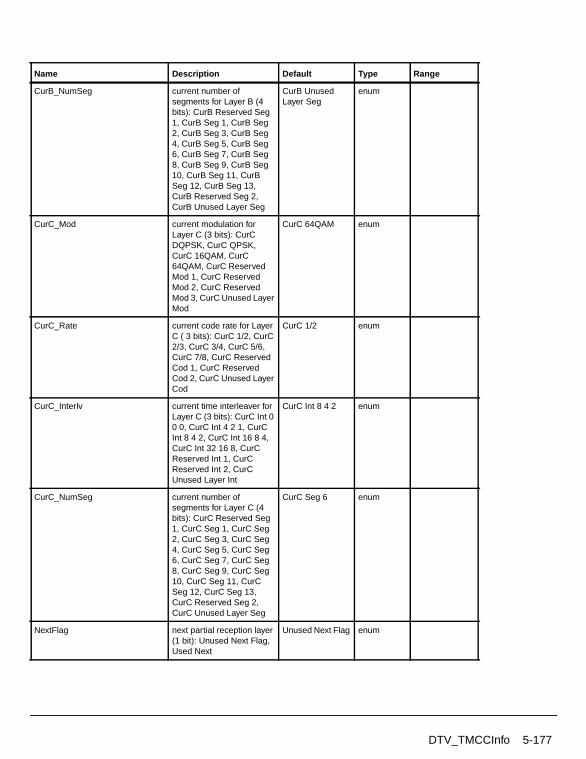
CurB_NumSeg current number ofsegments for Layer B (4bits): CurB Reserved Seg1, CurB Seg 1, CurB Seg2, CurB Seg 3, CurB Seg4, CurB Seg 5, CurB Seg6, CurB Seg 7, CurB Seg8, CurB Seg 9, CurB Seg10, CurB Seg 11, CurBSeg 12, CurB Seg 13,CurB Reserved Seg 2,CurB Unused Layer Seg
CurB UnusedLayer Seg
enum
CurC_Mod current modulation forLayer C (3 bits): CurCDQPSK, CurC QPSK,CurC 16QAM, CurC64QAM, CurC ReservedMod 1, CurC ReservedMod 2, CurC ReservedMod 3, CurC Unused LayerMod
CurC 64QAM enum
CurC_Rate current code rate for LayerC ( 3 bits): CurC 1/2, CurC2/3, CurC 3/4, CurC 5/6,CurC 7/8, CurC ReservedCod 1, CurC ReservedCod 2, CurC Unused LayerCod
CurC 1/2 enum
CurC_Interlv current time interleaver forLayer C (3 bits): CurC Int 00 0, CurC Int 4 2 1, CurCInt 8 4 2, CurC Int 16 8 4,CurC Int 32 16 8, CurCReserved Int 1, CurCReserved Int 2, CurCUnused Layer Int
CurC Int 8 4 2 enum
CurC_NumSeg current number ofsegments for Layer C (4bits): CurC Reserved Seg1, CurC Seg 1, CurC Seg2, CurC Seg 3, CurC Seg4, CurC Seg 5, CurC Seg6, CurC Seg 7, CurC Seg8, CurC Seg 9, CurC Seg10, CurC Seg 11, CurCSeg 12, CurC Seg 13,CurC Reserved Seg 2,CurC Unused Layer Seg
CurC Seg 6 enum
NextFlag next partial reception layer(1 bit): Unused Next Flag,Used Next
Unused Next Flag enum
Name Description Default Type Range
DTV_TMCCInfo 5-177

ISDB-T Components
NextA_Mod next modulation for Layer A(3 bits): NextA DQPSK,NextA QPSK, NextA16QAM, NextA 64QAM,NextA Reserved Mod 1,NextA Reserved Mod 2,NextA Reserved Mod 3,NextA Unused Layer Mod
NextA QPSK enum
NextA_Rate next code rate for Layer A (3 bits): NextA 1/2, NextA2/3, NextA 3/4, NextA 5/6,NextA 7/8, NextAReserved Cod 1, NextAReserved Cod 2, NextAUnused Layer Cod
NextA 1/2 enum
NextA_Interlv next time interleaving forLayer A (3 bits): NextA Int 00 0, NextA Int 4 2 1, NextAInt 8 4 2, NextA Int 16 8 4,NextA Int 32 16 8, NextAReserved Int 1, NextAReserved Int 2, NextAUnused Layer Int
NextA Int 8 4 2 enum
NextA_NumSeg next number of segmentsfor Layer A (4 bits): NextAReserved Seg 1, NextASeg 1, NextA Seg 2, NextASeg 3, NextA Seg 4, NextASeg 5, NextA Seg 6, NextASeg 7, NextA Seg 8, NextASeg 9, NextA Seg 10,NextA Seg 11, NextA Seg12, NextA Seg 13, NextAReserved Seg 2, NextAUnused Layer Seg
NextA ReservedSeg 1
enum
NextB_Mod next modulation for Layer B(3 bits): NextB DQPSK,NextB QPSK, NextB16QAM, NextB 64QAM,NextB Reserved Mod 1,NextB Reserved Mod 2,NextB Reserved Mod 3,NextB Unused Layer Mod
NextB 16QAM enum
NextB_Rate next code rate for Layer B (3 bits): NextB 1/2, NextB2/3, NextB 3/4, NextB 5/6,NextB 7/8, NextBReserved Cod 1, NextBReserved Cod 2, NextBUnused Layer Cod
NextB 1/2 enum
Name Description Default Type Range
5-178 DTV_TMCCInfo

NextB_Interlv next time interleaving forLayer B (3 bits): NextB Int 00 0, NextB Int 4 2 1, NextBInt 8 4 2, NextB Int 16 8 4,NextB Int 32 16 8, NextBReserved Int 1, NextBReserved Int 2, NextBUnused Layer Int
NextB Int 8 4 2 enum
NextB_NumSeg next number of segmentsfor Layer B (4 bits): NextBReserved Seg 1, NextBSeg 1, NextB Seg 2, NextBSeg 3, NextB Seg 4, NextBSeg 5, NextB Seg 6, NextBSeg 7, NextB Seg 8, NextBSeg 9, NextB Seg 10,NextB Seg 11, NextB Seg12, NextB Seg 13, NextBReserved Seg 2, NextBUnused Layer Seg
NextB Seg 6 enum
NextC_Mod next modulation for LayerC (3 bits): NextC DQPSK,NextC QPSK, NextC16QAM, NextC 64QAM,NextC Reserved Mod 1,NextC Reserved Mod 2,NextC Reserved Mod 3,NextC Unused Layer Mod
NextC QPSK enum
NextC_Rate next code rate for Layer C (3 bits): NextC 1/2, NextC2/3, NextC 3/4, NextC 5/6,NextC 7/8, NextCReserved Cod 1, NextCReserved Cod 2, NextCUnused Layer Cod
NextC 1/2 enum
NextC_Interlv next time interleaving forLayer C (3 bits): NextC Int0 0 0, NextC Int 4 2 1,NextC Int 8 4 2, NextC Int16 8 4, NextC Int 32 16 8,NextC Reserved Int 1,NextC Reserved Int 2,NextC Unused Layer Int
NextC Int 8 4 2 enum
Name Description Default Type Range
DTV_TMCCInfo 5-179

ISDB-T Components
Pin Outputs
Notes/Equations
1. This model is used to generate the 102 bits of TMCC information. For theparameters in this model, TMCC information bits are generated according toTable 5-28; specification bit assignments are given in Table 5-29 throughTable 5-37.
NextC_NumSeg next number of segmentsfor Layer C (4 bits): NextCReserved Seg 1, NextCSeg 1, NextC Seg 2, NextCSeg 3, NextC Seg 4, NextCSeg 5, NextC Seg 6, NextCSeg 7, NextC Seg 8, NextCSeg 9, NextC Seg 10,NextC Seg 11, NextC Seg12, NextC Seg 13, NextCReserved Seg 2, NextCUnused Layer Seg
NextC Seg 5 enum
FutureUse reserved for future use (allset to "1" 15 bits)
1 1 1 1 1 1 1 1 1 11 1 1 1 1
int array "111111111111111"
Pin Name Description Signal Type
1 output TMCC information bits (B20-B121) int
Table 5-28. Bit Assignments for TMCC Information
Bits No. of Bits Purpose/Content Reference
B20 − B212 System descriptor Table 5-30
B22 − B254 Countdown index Table 5-31
B26 1 Switch-on control flag used for alert broadcasting Table 5-32
B27 1 Currentconfigurationinformation
Partial-reception flag Table 5-33
B28 − B4013 Transmission parameters for layer a Table 5-29
B41 − B5313 Transmission parameters for layer b
B54 − B6613 Transmission parameters for layer c
Name Description Default Type Range
5-180 DTV_TMCCInfo

B67 1 Next configurationinformation
Partial-reception flag Table 5-33
B68 − B8013 Transmission parameters for layer a Table 5-29
B81 − B9313 Transmission parameters for layer b
B94 − B10613 Transmission parameters for layer c
B107 − B12115 (reserved for future use) All set to “1”
Table 5-29. Transmission Parameters
No. of Bits Reference
Modulation 3 Table 5-34Code Rate 3 Table 5-35Time Interleaving 3 Table 5-36Number of Segments 4 Table 5-37
Table 5-30. System Descriptor
B20 − B21 System
00 ISDB-T using 13 segments
01,10,11 (reserved for future use)
Table 5-31. Countdown Index
B22 − B25 Description
1111 15 Frames before changing transmission parameters
1110 14 Frames before changing transmission parameters
1101 13 Frames before changing transmission parameters
1100 12 Frames before changing transmission parameters
.
.
.
0010 3 Frames before changing transmission parameters
Table 5-28. Bit Assignments for TMCC Information (continued)
Bits No. of Bits Purpose/Content Reference
DTV_TMCCInfo 5-181

ISDB-T Components
0001 2 Frames before changing transmission parameters
0000 1 Frames before changing transmission parameters
Table 5-32. Switch-on Control Flag used for Albert Broadcasting
B26 Description
0 Ordinary
1 Switch-on
Table 5-33. Partial Reception Flag
B26, B27 Partial Reception Layer
0 Not used
1 Used
Table 5-34. Modulation Scheme of OFDM Carrier
Modulation
000 DQPSK
001 QPSK
010 16-QAM
011 64-QAM
100-110 Reserved
111 Not used
Table 5-35. Code Rate of Inner Code
Code Rate
000 1/2
001 2/3
010 3/4
011 5/6
100 7/8
Table 5-31. Countdown Index
B22 − B25 Description
5-182 DTV_TMCCInfo

References
101-110 Reserved
111 Not used
Table 5-36. Time Interleaving
Time Interleaving Parameter I
001 4(Mode 1), 4(Mode 2), 4(Mode 3)
010 8(Mode 1), 8(Mode 2), 8(Mode 3)
011 16(Mode 1), 16(Mode 2), 16(Mode 3)
100 32(Mode 1), 32(Mode 2), 32(Mode 3)
101-110 Reserved
111 Not used
Table 5-37. Number of Segments
No. of Segments used in Layer
0000 0
0001 1
0010 2
0011 3
0100 4
0101 5
0110 6
0111 7
1000 8
1001 9
1010 10
1011 11
1100 12
1101 13
1110 Reserved
1111 Not used
Table 5-35. Code Rate of Inner Code
Code Rate
DTV_TMCCInfo 5-183

ISDB-T Components
[1]ARIB-JAPAN, Terrestrial Integrated Services Digital Broadcasting (ISDB-T);Specification of Channel Coding, Framing Structure and Modulation,Sept.1998.
5-184 DTV_TMCCInfo

DTV_TMCCMod
Description TMCC differential modulationLibrary DTV, ISDB-TClass SDFDTV_TMCCMod
Parameters
Pin Inputs
Pin Outputs
Notes/Equations
1. The model performs DBPSK modulation.
2. B′[0] = B0; DBPSK modulation is:
B′[i] = Bi ⊕ B′i - 1
where i=1, 2, ... , 203.
Then
Name Description Default Type Range
Length length of TMCC bits perOFDM frame
204 int 204
Pin Name Description Signal Type
1 input received TMCC transmission format (204 bits)before modulation in the transmitter
int
Pin Name Description Signal Type
2 output modulated TMCC transmission format complex
DTV_TMCCMod 5-185

ISDB-T Components
coded bits B′[0] ~ B′ [203] are converted to 1.0, 0, -1.0, 0.
where i=0,1, ... , 203.
References
[1]ARIB-JAPAN, Terrestrial Integrated Services Digital Broadcasting (ISDB-T);Specification of Channel Coding, Framing Structure and Modulation,Sept.1998.
x i[ ] 1 j0+= if B′ i[ ] 0=( )
x i[ ] 1– j0+= if B′ i[ ] 1=( )
5-186 DTV_TMCCMod

DTV_TimeInterlv
Description Interleaver and deinterleaver of complex dataLibrary DTV, ISDB-TClass SDFDTV_TimeInterlv
Parameters
Pin Inputs
Pin Outputs
Name Description Default Type Range
Carriers numbers of carriers in eachsegment for specific OFDMmodulation mode
96 int 96, 192,384†
Segments number of segments to beinterleaved simultaneously
13 int [1, 13]
Option option for interleaving orde-interleaving: Interleave,Deinterleave
Interleave enum
Initial_value initial value in interleaverdelay FIFOs
0.0+j*0.0 complex [0, ∞)
I factor to multiply whencaculating delay period forinterleaver branches
0 int [0, 32]
InitialType interleaver delay FIFOsinitial value type: Const,QPSK, QAM 16, QAM 64
Const enum
† Carriers = 96, 192, 384 for mode 1, 2, 3, respectively
Pin Name Description Signal Type
1 input input symbols to be interleaved complex
Pin Name Description Signal Type
2 output output symbols after interleaved complex
DTV_TimeInterlv 5-187
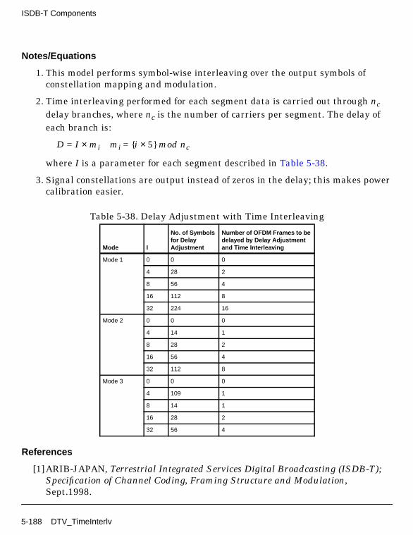
ISDB-T Components
Notes/Equations
1. This model performs symbol-wise interleaving over the output symbols ofconstellation mapping and modulation.
2. Time interleaving performed for each segment data is carried out through ncdelay branches, where nc is the number of carriers per segment. The delay ofeach branch is:
D = I × mi mi = i × 5 mod nc
where I is a parameter for each segment described in Table 5-38.
3. Signal constellations are output instead of zeros in the delay; this makes powercalibration easier.
References
[1]ARIB-JAPAN, Terrestrial Integrated Services Digital Broadcasting (ISDB-T);Specification of Channel Coding, Framing Structure and Modulation,Sept.1998.
Table 5-38. Delay Adjustment with Time Interleaving
Mode I
No. of Symbolsfor DelayAdjustment
Number of OFDM Frames to bedelayed by Delay Adjustmentand Time Interleaving
Mode 1 0 0 0
4 28 2
8 56 4
16 112 8
32 224 16
Mode 2 0 0 0
4 14 1
8 28 2
16 56 4
32 112 8
Mode 3 0 0 0
4 109 1
8 14 1
16 28 2
32 56 4
5-188 DTV_TimeInterlv

Chapter 6: Multiplex Components
6-1

Multiplex Components
DTV_CommCtrl2
Description 2-input commutator with input particle number controlLibrary DTV, MultiplexClass SDFDTV_CommCtrl2
Parameters
Pin Inputs
Pin Outputs
Notes/Equations
1. This model is used to combine two input signals into one.
NumInput1 of input 1 and NumOutput2 of input 2 data particles are combinedand output.
Name Description Default Type Range
NumInput1 number of particles frominput 1
1 int [1, ∞)
NumInput2 number of particles frominput 2
1 int [1, ∞)
Pin Name Description Signal Type
1 in1 input 1 anytype
2 in2 input 2 anytype
Pin Name Description Signal Type
3 output output comprised of two inputs anytype
6-2 DTV_CommCtrl2

DTV_CommCtrl3
Description 3-input commutator with input particle number controlLibrary DTV, MultiplexClass SDFDTV_CommCtrl3
Parameters
Pin Inputs
Pin Outputs
Notes/Equations
1. This model is used to combine three input signals into one.
NumInput1 of input 1, NumOutput2 of input 2, and NumInput3 of input 3 dataparticles are combined and output.
Name Description Default Type Range
NumInput1 number of particles frominput 1
1 int [1, ∞)
NumInput2 number of particles frominput 2
1 int [1, ∞)
NumInput3 number of particles frominput 3
1 int [1, ∞)
Pin Name Description Signal Type
1 in1 input 1 anytype
2 in2 input 2 anytype
3 in3 input 3 anytype
Pin Name Description Signal Type
4 output output comprised of three inputs anytype
DTV_CommCtrl3 6-3

Multiplex Components
DTV_DistCtrl2
Description 2-output distributor with output particle number controlLibrary DTV, MultiplexClass SDFDTV_DistCtrl2
Parameters
Pin Inputs
Pin Outputs
Notes/Equations
1. This model is used to distribute one data stream to two outputs.
NumOutput1 and NumOutput2 data particles are distributed to output 1, andoutput 2, respectively.
Name Description Default Type Range
NumOutput1 number of particlesdirected to output 1
1 int [1, ∞)
NumOutput2 number of particlesdirected to output 2
1 int [1, ∞)
Pin Name Description Signal Type
1 input input to be distributed over the two outputs anytype
Pin Name Description Signal Type
2 out1 output 1 anytype
3 out2 output 2 anytype
6-4 DTV_DistCtrl2

DTV_DistCtrl3
Description 3-output distributor with output particle number controlLibrary DTV, MultiplexClass SDFDTV_DistCtrl3
Parameters
Pin Inputs
Pin Outputs
Notes/Equations
1. This model is used to distribute one data stream to three outputs.
NumOutput1, NumOutput2 and NumOutput3 data particles are distributed tooutput 1, output 2, and output 3, respectively.
Name Description Default Type Range
NumOutput1 number of particlesdirected to output 1
1 int [1, ∞)
NumOutput2 number of particlesdirected to output 2
1 int [1, ∞)
NumOutput3 number of particlesdirected to output 3
1 int [1, ∞)
Pin Name Description Signal Type
1 input input to be distributed over the three outputs anytype
Pin Name Description Signal Type
2 out1 output 1 anytype
3 out2 output 2 anytype
4 out3 output 3 anytype
DTV_DistCtrl3 6-5

Multiplex Components
DTV_SplitThreeLayData
Description Data stream splitter into 3-layer dataLibrary DTV, MultiplexClass SDFDTV_SplitThreeLayData
Parameters
Pin Inputs
Pin Outputs
Name Description Default Type Range
Carriers number of carriers in onesegment
432 int 96,108,192,216,384,432†
SegmentsA number of segments inlayer A
1 int 1††
SegmentsB number of segments inlayer B
1 int [1, 12]††
SegmentsC number of segments inlayer C
1 int [1, 12]††
† According to ISDB-T, the Carriers are 96 and 108, 192 and 216, 384 and 432, corresponding to mode 1, mode 2,and mode 3, respectively.
†† The sum of SegmentsA, SegmentsB, and SegmentsC ≤ 13.
Pin Name Description Signal Type
1 Synt synthesis of 3-layer data streams complex
Pin Name Description Signal Type
2 LayA layer A output complex
3 LayB layer B output complex
4 LayC layer C output complex
6-6 DTV_SplitThreeLayData
Notes/Equations
1. The model is used to demultiplex one synthetic stream into a 3-layer datastream for use in ISDB-T 3-layer systems only.
Each firing, Synt consumes (SegmentsA+SegmentsB+SegmentsC)×Carrierstokens; LayA produces SegmentsA×Carriers tokens; LayB producesSegmentsB×Carriers tokens; LayC produces SegmentsC×Carriers tokens.
References
[1]ARIB-JAPAN, Terrestrial Integrated Services Digital Broadcasting (ISDB-T);Specification of Channel Coding, Framing Structure and Modulation,Sept.1998.
DTV_SplitThreeLayData 6-7

Multiplex Components
DTV_SplitThreeLayTSP
Description TSP stream splitter into 3-layer TSP streamLibrary DTV, MultiplexClass SDFDTV_SplitThreeLayTSP
Parameters
Name Description Default Type Range
Length number of bytes in oneTSP
204 int 204
SegmentsA number of segments inlayer A
1 int 1†
LayerA_Modulation modulation mode for layerA: A DQPSK, A QPSK, A16QAM, A 64QAM
A DQPSK enum
LayerA_Convolutional_Code convolutional code rate forlayer A: A 1/2, A 2/3, A 3/4,A 5/6, A 7/8
A 1/2 enum
SegmentsB number of segments inlayer B
5 int [1, 12]†
LayerB_Modulation modulation mode for LayerB: B DQPSK, B QPSK, B16QAM, B 64QAM
B QPSK enum
LayerB_Convolutional_Code convolutional code rate forlayer B: B 1/2, B 2/3, B 3/4,B 5/6, B 7/8
B 7/8 enum
SegmentsC number of segments inlayer C
7 int [1, 12]†
LayerC_Modulation modulation mode for layerC: C DQPSK, C QPSK, C16QAM, C 64QAM
C 64QAM enum
LayerC_Convolutional_Code convolutional code rate forlayer C: C 1/2, C 2/3, C 3/4,C 5/6, C 7/8
C 7/8 enum
† The sum of SegmentsA, SegmentsB and SegmentsC ≤ 13.
6-8 DTV_SplitThreeLayTSP

Pin Inputs
Pin Outputs
Notes/Equations
1. This model is used in ISDB-T 3-layer systems to split one TSP data stream intoa 3-layer TSP data stream according to Table 6-1.
2. One TSP data stream is split into a 3-layer TSP data stream: layer A, layer B,and layer C.
The number of TSPs per segment in each layer is determined according tomodulation mode and convolutional code rate.
The model determines the total number of TSPs in each layer by the number ofTSPs per segments and the number of segments in each layer in one OFDMframe. To increase simulation speed, the total number of TSPs in each layer isdivided by the greatest common divisor, which is the greatest common divisor ofthe total number of TSPs in each layer. An example follows for mode 1.
SegmentsA=1LayerA_Modulation= A 64QAMLayerA_Convolutional_Code= A 2/3
SegmentsB=5LayerB_Modulation= B DQPSKLayerB_Convolutional_Code= B 1/2
SegmentsC=7LayerC_Modulation= C 16QAMLayerC_Convolutional_Code= C 3/4
Referring to Table 6-1, the number of TSPs is 48, 12, and 36 per segment,respectively.
Pin Name Description Signal Type
1 input input TSP data stream to be split int
Pin Name Description Signal Type
2 OutA layer A output int
3 OutB layer B output int
4 OutC layer C output int
DTV_SplitThreeLayTSP 6-9

Multiplex Components
The total number of TSPs in each layer is 48×1, 12×5 and 36×7 in one OFDMframe; the greatest common divisor is 12. After dividing, the total number ofTSPs is 4, 5 and 21, respectively. Then, the model splits 204×4×1 integers toOutA pin, 204×1×5 integers to OutB pin, and 204×3×7 integers to OutC pin.
References
[1]ARIB-JAPAN, Terrestrial Integrated Services Digital Broadcasting (ISDB-T);Specification of Channel Coding, Framing Structure and Modulation,Sept.1998.
Table 6-1. Transmitting TSPs per Segment for ISDB-T
Carrier Modulation Convolutional Code
Number of Transmitting
TSPs† (Mode 1/2/3)
DQPSK, QPSK 1/2 12/24/48
2/3 16/32/64
3/4 18/36/72
5/6 20/40/80
7/8 21/42/84
16-QAM 1/2 24/48/96
2/3 32/64/128
3/4 36/72/144
5/6 40/80/160
7/8 42/84/168
64-QAM 1/2 36/72/144
2/3 48/96/192
3/4 54/108/216
5/6 60/120/240
7/8 63/126/252
†number of transmitting TSPs per one OFDM frame
6-10 DTV_SplitThreeLayTSP

DTV_SplitTwoLayData
Description Data stream splitter into 2-layer dataLibrary DTV, MultiplexClass SDFDTV_SplitTwoLayData
Parameters
Pin Inputs
Pin Outputs
Notes/Equations
Name Description Default Type Range
Carriers number of carriers in onesegment
432 int 96,108,192,216,384,432†
SegmentsA number of segments inlayer A
1 int [1, 12]††
SegmentsB number of segments inlayer B
1 int [1, 12]††
† According to ISDB-T, the number of Carriers is 96 and 108, 192 and 216, 384 and 432, corresponding to mode 1,mode 2, and mode 3, respectively.
†† The sum of SegmentsA and SegmentsB ≤ 13.
Pin Name Description Signal Type
1 Synt synthesis of 2-layer data stream complex
Pin Name Description Signal Type
2 LayA layer A output complex
3 LayB layer B output complex
DTV_SplitTwoLayData 6-11

Multiplex Components
1. The model is used in ISDB-T 2-layer systems to demultiplex one syntheticstream into a 2-layer data stream.
2. Each firing, Synt consumes (SegmentsA+SegmentsB)×Carriers tokens; LayAproduces SegmentsA×Carriers tokens; LayB produces SegmentsB×Carrierstokens.
References
[1]ARIB-JAPAN, Terrestrial Integrated Services Digital Broadcasting (ISDB-T);Specification of Channel Coding, Framing Structure and Modulation,Sept.1998.
6-12 DTV_SplitTwoLayData

DTV_SplitTwoLayTSP
Description TSP stream splitter into 2-layer TSP streamLibrary DTV, MultiplexClass SDFDTV_SplitTwoLayTSP
Parameters
Pin Inputs
Name Description Default Type Range
Length number of bytes in oneTSP
204 int 204
SegmentsA number of segments inlayer A
5 int [1, 12]†
LayerA_Modulation modulation mode for layerA: A DQPSK, A QPSK, A16QAM, A 64QAM
A DQPSK enum
LayerA_Convolutional_Code convolutional code rate forlayer A: A 1/2, A 2/3, A 3/4,A 5/6, A 7/8
A 1/2 enum
SegmentsB number of segments inlayer B
8 int [1, 12]†
LayerB_Modulation modulation mode for layerB: B DQPSK, B QPSK, B16QAM, B 64QAM
B DQPSK enum
LayerB_Convolutional_Code convolutional code rate forlayer B: B 1/2, B 2/3, B 3/4,B 5/6, B 7/8
B 7/8 enum
† The sum of SegmentsA and SegmentsB≤ 13.
Pin Name Description Signal Type
1 input input TSP data stream to be split int
DTV_SplitTwoLayTSP 6-13

Multiplex Components
Pin Outputs
Notes/Equations
1. This model is used in ISDB-T 2-layer systems to split one TSP data stream intoa 2-layer TSP data stream according to Table 6-2.
2. The TSP stream is split into a 2-layer TSP data stream: layer A and layer B.The number of TSPs per segment in each layer is determined according tomodulation mode and convolutional code rate.
The total number of TSPs in each layer is determined by the number of TSPsper segments and the number of segments in each layer in one OFDM frame. Toincrease simulation speed, the total number of TSPs in each layer is divided bythe greatest common divisor, which is the greatest common divisor between thetotal number of TSPs in each layer. An example follows for mode 1.
SegmentsA=5LayerA_Modulation= A DQPSKLayerA_Convolutional_Code= A 1/2
SegmentsB=7LayerB_Modulation= B 16QAMLayerB_Convolutional_Code= B 3/4
Referring to Table 6-2, the number of TSPs is 12 and 36 per segment,respectively. The total number of TSPs in each layer is 12×5 and 36×7 in oneOFDM frame; the greatest common divisor is 12. After dividing, the totalnumber of TSPs is 5 and 21, respectively. So, the model distributes 204×1×5integers to OutA pin, and 204×3×7 integers to OutB pin.
Pin Name Description Signal Type
2 OutA layer A output int
3 OutB layer B output int
6-14 DTV_SplitTwoLayTSP

References
[1]ARIB-JAPAN, Terrestrial Integrated Services Digital Broadcasting (ISDB-T);Specification of Channel Coding, Framing Structure and Modulation,Sept.1998.
Table 6-2. Transmitting TSPs per Segment for ISDB-T
Carrier Modulation Convolutional Code
Number of Transmitting
TSPs† (Mode 1/2/3)
DQPSK, QPSK 1/2 12/24/48
2/3 16/32/64
3/4 18/36/72
5/6 20/40/80
7/8 21/42/84
16-QAM 1/2 24/48/96
2/3 32/64/128
3/4 36/72/144
5/6 40/80/160
7/8 42/84/168
64-QAM 1/2 36/72/144
2/3 48/96/192
3/4 54/108/216
5/6 60/120/240
7/8 63/126/252
†number of transmitting TSPs per one OFDM frame
DTV_SplitTwoLayTSP 6-15

Multiplex Components
DTV_SynLayTMCC1
Description Synthesizer for 1-layer TMCC received into one TMCC formatLibrary DTV, MultiplexClass SDFDTV_SynLayTMCC1
Parameters
Pin Inputs
Pin Outputs
Notes/Equations
1. The model is used in ISDB-T 1-layer systems to synthesize one layer TMCCstreams into one synthetic stream.
2. Because there is one received TMCC signal from each segment in every layer inthe DTV_DemuxCohSegs and DTV_DemuxDiffSegs models, all TMCC receivedmust be synthesized to one TMCC signal, as follows.
Complex in(0.0,0.0),out(0.0,0.0);for (int i=0; i<seg ;i++)in += (input%(i)).operator Complex();out = in/seg;
output%(0) << out;
Name Description Default Sym Type Range
Segments number of segments 1 seg int [1, 13]
Pin Name Description Signal Type
1 input 1-layer input complex
Pin Name Description Signal Type
2 output synthesis of 1-layer TMCC stream complex
6-16 DTV_SynLayTMCC1

References
[1]ARIB-JAPAN, Terrestrial Integrated Services Digital Broadcasting (ISDB-T);Specification of Channel Coding, Framing Structure and Modulation,Sept.1998.
DTV_SynLayTMCC1 6-17

Multiplex Components
DTV_SynLayTMCC2
Description Synthesizer for 2-layer TMCC received into one TMCC formatLibrary DTV, MultiplexClass SDFDTV_SynLayTMCC2
Parameters
Pin Inputs
Pin Outputs
Notes/Equations
1. The model is used to synthesize 2-layer TMCC streams into one syntheticstream, for use in ISDB-T 2-layer systems.
Name Description Default Sym Type Range
SegmentsA number of segments inlayer A
1 segA int [1, 12]†
SegmentsB number of segments inlayer B
1 segB int [1, 12]†
† The sum of SegmentsA and SegmentsB ≤ 13.
Pin Name Description Signal Type
1 LayA layer A input complex
2 LayB layer B input complex
Pin Name Description Signal Type
3 Synt synthesis of 2-layer TMCC streams complex
6-18 DTV_SynLayTMCC2

2. Because there is one received TMCC signal from each segment in every layer inthe DTV_DemuxCohSegs and DTV_DemuxDiffSegs models, all received TMCCmust be synthesized to one TMCC signal, as follows.
Complex in1(0.0,0.0),in2(0.0,0.0),out(0.0,0.0);for (int i=0; i<segA ;i++)in1 += (LayA%(i)).operator Complex();
for ( i=0; i<segB ;i++)in2 += (LayB%(i)).operator Complex();out = (in1+in2)/sumAB;Synt%(0) << out;
References
[1]ARIB-JAPAN, Terrestrial Integrated Services Digital Broadcasting (ISDB-T);Specification of Channel Coding, Framing Structure and Modulation,Sept.1998.
DTV_SynLayTMCC2 6-19

Multiplex Components
DTV_SynLayTMCC3
Description Synthesizer for 3-layer TMCC received into one TMCC formatLibrary DTV, MultiplexClass SDFDTV_SynLayTMCC3
Parameters
Pin Inputs
Pin Outputs
Notes/Equations
Name Description Default Sym Type Range
SegmentsA number of segments inlayer A
1 segA int 1†, ††
SegmentsB number of segments inlayer B
1 segB int [1, 12]††
SegmentsC number of segments inlayer C
1 segC int [1, 12]††
† According to ISDB-T, the number of segments in the first layer must be 1.
†† The sum of SegmentsA, SegmentsB and SegmentsC ≤ 13.
Pin Name Description Signal Type
1 LayA layer A input complex
2 LayB layer B input complex
3 LayC layer C input complex
Pin Name Description Signal Type
4 Synt synthesis of 3-layer TMCC streams complex
6-20 DTV_SynLayTMCC3

1. This model is used in ISDB-T 3-layer systems to synthesize 3-layer TMCCstreams into one synthetic stream.
2. Because there is one received TMCC signal from each segment in every layer inthe DTV_DemuxCohSegs and DTV_DemuxDiffSegs models, all received TMCCmust be synthesized into one TMCC signal, as follows.
Complex in1(0.0,0.0),in2(0.0,0.0),in3(0.0,0.0),out(0.0,0.0);for (int i=0; i<segA;i++)
in1 += (LayA%(i)).operator Complex();for ( i=0; i<segB;i++)
in2 += (LayB%(i)).operator Complex();for ( i=0; i<segC;i++)
in3 += (LayC%(i)).operator Complex();out = (in1+in2+in3)/sumABC;Synt%(0) << out;
References
[1]ARIB-JAPAN, Terrestrial Integrated Services Digital Broadcasting (ISDB-T);Specification of Channel Coding, Framing Structure and Modulation,Sept.1998.
DTV_SynLayTMCC3 6-21

Multiplex Components
DTV_SynThreeLayData
Description Synthesizer for 3-layer data into one streamLibrary DTV, MultiplexClass SDFDTV_SynThreeLayData
Parameters
Pin Inputs
Pin Outputs
Name Description Default Type Range
Carriers number of carriers in onesegment
432 int 96,108,192,216,384,432†
SegmentsA number of segments inlayer A
1 int 1††, †††
SegmentsB number of segments inlayer B
1 int [1, 12]†††
SegmentsC number of segments inlayer C
1 int [1, 12]†††
† According to ISDB-T, the Carriers should be 96 and 108, 192 and 216, 384 and 432, corresponding to mode 1,mode 2, and mode 3, respectively.†† According to ISDB-T, the number of segments in the first layer must be 1.
††† The sum of SegmentsA, SegmentsB and SegmentsC ≤ 13.
Pin Name Description Signal Type
1 LayA layer A input complex
2 LayB layer B input complex
3 LayC layer C input complex
Pin Name Description Signal Type
4 Synt synthesis of 3-layer data streams complex
6-22 DTV_SynThreeLayData

Notes/Equations
1. This model is used in ISDB-T 3-layer systems to multiplex 3-layer data streamsinto one synthetic stream.
2. Each firing, LayA consumes SegmentsA×Carriers tokens; LayB consumesSegmentsB×Carriers tokens; LayC consumes SegmentsC×Carriers tokens; Syntproduces (SegmentsA+SegmentsB+SegmentsC)×Carriers tokens.
References
[1]ARIB-JAPAN, Terrestrial Integrated Services Digital Broadcasting (ISDB-T);Specification of Channel Coding, Framing Structure and Modulation,Sept.1998.
DTV_SynThreeLayData 6-23

Multiplex Components
DTV_SynThreeLayTSP
Description Synthesizer for 3-layer TSP into one TSP streamLibrary DTV, MultiplexClass SDFDTV_SynThreeLayTSP
Parameters
Name Description Default Type Range
Length number of bytes in oneTSP
204 int 204
SegmentsA number of segments inlayer A
1 int 1†
LayerA_Modulation modulation mode for layerA: A DQPSK, A QPSK, A16QAM, A 64QAM
A DQPSK enum
LayerA_Convolutional_Code convolutional code rate forlayer A: A 1/2, A 2/3, A 3/4,A 5/6, A 7/8
A 1/2 enum
SegmentsB number of segments inlayer B
5 int [1, 12]†
LayerB_Modulation modulation mode for layerB: B DQPSK, B QPSK, B16QAM, B 64QAM
B QPSK enum
LayerB_Convolutional_Code convolutional code rate forlayer B: B 1/2, B 2/3, B 3/4,B 5/6, B 7/8
B 7/8 enum
SegmentsC number of segments inlayer C
7 int [1, 12]†
LayerC_Modulation modulation mode for layerC: C DQPSK, C QPSK, C16QAM, C 64QAM
C 64QAM enum
LayerC_Convolutional_Code convolutional code rate forlayer C: C 1/2, C 2/3, C 3/4,C 5/6, C 7/8
C 7/8 enum
† The sum of SegmentsA, SegmentsB and SegmentsC ≤ 13.
6-24 DTV_SynThreeLayTSP

Pin Inputs
Pin Outputs
Notes/Equations
1. This model is used in ISDB-T 3-layer systems to synthesize 3-layer TSPstreams into one TSP stream, according to Table 6-3.
2. The model synthesizes the 3-layer TSP streams (layer A, layer B, and layer C)into one TSP stream.
The number of TSPs per segment in each layer is determined according tomodulation mode and convolutional code rate.
The model determines the total number of TSPs in each layer by the number ofTSPs per segments and the number of segments in each layer in one OFDMframe. To increase simulation speed, the total number of TSPs in each layer isdivided by the greatest common divisor, which is the greatest common divisor ofthe total number of TSPs in each layer. An example follows for mode 1.
SegmentsA=1LayerA_Modulation= A 64QAMLayerA_Convolutional_Code= A 2/3
SegmentsB=5LayerB_Modulation= B DQPSKLayerB_Convolutional_Code= B 1/2
SegmentsC=7LayerC_Modulation= C 16QAMLayerC_Convolutional_Code= C 3/4
Pin Name Description Signal Type
1 InA layer A input int
2 InB layer B input int
3 InC layer B input int
Pin Name Description Signal Type
4 output output TSP stream comprised of 3-layer TSPstreams
int
DTV_SynThreeLayTSP 6-25

Multiplex Components
Referring to Table 6-3, the number of TSPs is 48, 12, and 36 per segment,respectively. The total number of TSPs in each layer is 48×1, 12×5 and 36×7 inone OFDM frame; the greatest common divisor is 12. After dividing, the totalnumber of TSPs is 4, 5 and 21, respectively. Then, the model combines 204×4×1integers in InA pin, 204×1×5 integers in InB pin, and 204×3×7 integers in InCpin into the output TSP stream.
References
[1]ARIB-JAPAN, Terrestrial Integrated Services Digital Broadcasting (ISDB-T);Specification of Channel Coding, Framing Structure and Modulation,Sept.1998.
Table 6-3. Transmitting TSPs per Segment for ISDB-T
Carrier Modulation Convolutional Code
Number of Transmitting
TSPs† (Mode 1/2/3)
DQPSK, QPSK 1/2 12/24/48
2/3 16/32/64
3/4 18/36/72
5/6 20/40/80
7/8 21/42/84
16-QAM 1/2 24/48/96
2/3 32/64/128
3/4 36/72/144
5/6 40/80/160
7/8 42/84/168
64-QAM 1/2 36/72/144
2/3 48/96/192
3/4 54/108/216
5/6 60/120/240
7/8 63/126/252
†number of transmitting TSPs per one OFDM frame
6-26 DTV_SynThreeLayTSP

DTV_SynTwoLayData
Description Synthesizer for 2-layer data into one streamLibrary DTV, MultiplexClass SDFDTV_SynTwoLayData
Parameters
Pin Inputs
Pin Outputs
Notes/Equations
Name Description Default Type Range
Carriers number of carriers in onesegment
432 int 96,108,192,216,384,432†
SegmentsA number of segments inlayer A
1 int [1, 12]††
SegmentsB number of segments inlayer B
1 int [1, 12]††
† According to ISDB-T, Carriers should be 96 and 108, 192 and 216, 384 and 432, corresponding to mode 1, mode2, and mode 3, respectively.
†† The sum of SegmentsA and SegmentsB ≤ 13.
Pin Name Description Signal Type
1 LayA layer A input complex
2 LayB layer B input complex
Pin Name Description Signal Type
3 Synt synthesis of 2-layer data streams complex
DTV_SynTwoLayData 6-27

Multiplex Components
1. This model is used in ISDB-T 2-layer systems to multiplex 2-layer data streamsinto one synthetic stream.
2. Each firing, LayA consumes SegmentsA×Carriers tokens; LayB consumesSegmentsB×Carriers tokens; Synt produces (SegmentsA+SegmentsB)×Carrierstokens.
References
[1]ARIB-JAPAN, Terrestrial Integrated Services Digital Broadcasting (ISDB-T);Specification of Channel Coding, Framing Structure and Modulation,Sept.1998.
6-28 DTV_SynTwoLayData

DTV_SynTwoLayTSP
Description Synthesizer for 2-layer TSP into one TSP streamLibrary DTV, MultiplexClass SDFDTV_SynTwoLayTSP
Parameters
Pin Inputs
Name Description Default Type Range
Length number of bytes in oneTSP
204 int 204
SegmentsA number of segments inlayer A
5 int [1, 12]†
LayerA_Modulation modulation mode for layerA: A DQPSK, A QPSK, A16QAM, A 64QAM
A DQPSK enum
LayerA_Convolutional_Code convolutional code rate forlayer A: A 1/2, A 2/3, A 3/4,A 5/6, A 7/8
A 1/2 enum
SegmentsB number of segments inlayer B
8 int [1, 12]†
LayerB_Modulation modulation mode for LayerB: B DQPSK, B QPSK, B16QAM, B 64QAM
B DQPSK enum
LayerB_Convolutional_Code convolutional code rate forlayer B: B 1/2, B 2/3, B 3/4,B 5/6, B 7/8
B 7/8 enum
† The sum of SegmentsA and SegmentsB≤ 13.
Pin Name Description Signal Type
1 InA layer A input int
2 InB layer B input int
DTV_SynTwoLayTSP 6-29

Multiplex Components
Pin Outputs
Notes/Equations
1. This model is used in ISDB-T 2-layer systems to synthesize a 2-layer TSPstream into one TSP stream according to Table 6-4.
2. Layers A and layer B are synthesized into one TSP stream. The number of TSPsper segment in each layer is determined according to modulation mode andconvolutional code rate.
The model determines the total number of TSPs in each layer by the number ofTSPs per segment and the number of segments in each layer in one OFDMframe. To increase simulation speed, the total number of TSPs in each layer isdivided by the greatest common divisor, which is the greatest common divisor ofthe total numbers of TSPs in each layer. An example follows for mode 1.
SegmentsA=5LayerA_Modulation= A DQPSKLayerA_Convolutional_Code= A 1/2
SegmentsB=7LayerB_Modulation= B 16QAMLayerB_Convolutional_Code= B 3/4
According to Table 6-4, the number of TSPs is 12, and 36 per segment,respectively. The total number of TSPs in each layer is 12×5 and 36×7 in oneOFDM frame; the greatest common divisor is 12. After dividing, the totalnumber of TSPs is 5 and 21, respectively. Then, the model combines 204×5×1integers in InA pin and 204×3×7 integers in InB pin into the output TSPstream.
Pin Name Description Signal Type
3 output output TSP stream comprised of 2-layer TSPstreams
int
6-30 DTV_SynTwoLayTSP

References
[1]ARIB-JAPAN, Terrestrial Integrated Services Digital Broadcasting (ISDB-T);Specification of Channel Coding, Framing Structure and Modulation,Sept.1998.
Table 6-4. Transmitting TSPs per Segment for ISDB-T
Carrier Modulation Convolutional Code
Number of Transmitting
TSPs†(Mode 1/2/3)
DQPSK, QPSK 1/2 12/24/48
2/3 16/32/64
3/4 18/36/72
5/6 20/40/80
7/8 21/42/84
16-QAM 1/2 24/48/96
2/3 32/64/128
3/4 36/72/144
5/6 40/80/160
7/8 42/84/168
64-QAM 1/2 36/72/144
2/3 48/96/192
3/4 54/108/216
5/6 60/120/240
7/8 63/126/252
†number of transmitting TSPs per one OFDM frame
DTV_SynTwoLayTSP 6-31

Multiplex Components
6-32

Chapter 7: OFDM Components
7-1
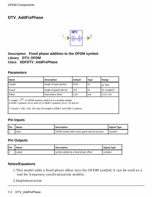
OFDM Components
DTV_AddFixPhase
Description Fixed phase addition to the OFDM symbolLibrary DTV, OFDMClass SDFDTV_AddFixPhase
Parameters
Pin Inputs
Pin Outputs
Notes/Equations
1.This model adds a fixed phase offset into the OFDM symbol; it can be used as atool for frequency synchronization models.
2.Implementation
Name Description Default Type Range
Length length of input symbol 8192 int (0, ∞)†
Guard length of guard interval 512 int (0, Length]††
Offset fixed phase offset 0.25 real (-0.5, 0.5)
† Length = 2N in OFDM systems; where N is a positive integer.In DVB-T systems, N=11 and 13; in ISDB-T systems, N=11, 12 and 13.
†† Guard = 1/32, 1/16, 1/8, and 1/4 Length in ISDB-T and DVB-T systems.
Pin Name Description Signal Type
1 input OFDM symbol after insert guard interval process complex
Pin Name Description Signal Type
2 output symbol added by a fixed phase offset complex
7-2 DTV_AddFixPhase

Assume x(0), x(1), ... , x(N−1) are the transmitted symbols that are combinedinto an OFDM symbol. Add a fixed phase offset Φ into OFDM symbol, we canget y(0), y(1), ... , y(N−1), as follows:
where Φ is the carrier phase offset value (-0.5,0.5). We add the fixed phase offsetin the ±0.5 subcarriers OFDM symbol. N is the sum of the length of IFFT andthe interval guard.
References
[1]J.J. van de Beek, M. Sandell, and P.O.Borjesson, On Synchronization in OFDMSystems Using the Cyclic Prefix, in Proceedings of Radio VetenskapligKonferens (REVK’96), pp.663-667, Lulea Sweden, June 1996.
[2] ARIB-JAPAN, Terrestrial Integrated Services Digital Broadcasting (ISDB-T);Specification of Channel Coding, Framing Structure and Modulation,Sept.1998.
[3] ETSI, Digital Video Broadcasting (DVB); Framing structure, channel codingand modulation for digital terrestrial television. EN300 744 v1.2.1, EuropeanTelecommunication Standard, July 1999.
y i( ) x i( )ej2πΦi
N-----------------
=
DTV_AddFixPhase 7-3

OFDM Components
DTV_InsertGuard
Description Guard interval inserterLibrary DTV, OFDMClass SDFDTV_InsertGuard
Parameters
Pin Inputs
Pin Outputs
Notes/Equations
1.This model inserts a guard interval after the IFFT procedure.
2.Implementation
Name Description Default Type Range
Length length of input symbol 8192 int (0, ∞)†
Guard length of guard interval 512 int (0, Length]††
† Length = 2N in OFDM systems; where N is a positive integer.In DVB-T systems, N=11 and 13; in ISDB-T systems, N=11, 12 and 13.
††Guard = 1/32, 1/16, 1/8, and 1/4 Length in ISDB-T and DVB-T systems.
Pin Name Description Signal Type
1 input signal from the IFFT complex
Pin Name Description Signal Type
2 output signal output after guard interval insertion complex
7-4 DTV_InsertGuard

Assume x(0), x(1), ... , x(N−1)are the N symbols from IFFT. The guard interval(interval length is Ng) is inserted as follows:
x(−i) = x(N − i) i = 1, 2, ... , Ng
After insertion of the guard interval, the length of the output signal is N + Ng ,the output signal is
x(−Ng), ... , x(− 1), x(0), x(1), ... , x (N − 1)
Guard interval insertion is shown in Figure 7-1.
Figure 7-1. Guard Interval Insertion
GuardInterval Effective Symbol Duration
GuardInterval Effective Symbol Duration
IFFT Output DataIFFT Output Data
DTV_InsertGuard 7-5

OFDM Components
DTV_LoadFFTBuff
Description Received data loader from channel to FFT bufferLibrary DTV, OFDMClass SDFDTV_LoadFFTBuff
Parameters
Pin Inputs
Name Description Default Type Range
InLength length of input sequence 2048 int [0, ∞)†
Order FFT points=2^Order 11 int [1, ∞)††
MinDelay min delay from 0 toInLength-1
0 int (0, InLength]
MaxDelay max delay from 0 toInLength-1
2047 int [MinDelay,InLength]
Offset offset from ML peak tosymbol start point
256 int [-MinDelay, 2 *
InLength-2Order -MaxDelay)†††
† InLength = 2N in OFDM systems; where N is a positive integer.N=11 and 13 in DVB-T systems; N=11, 12, and 13 in ISDB-T systems.†† Order=11 and 13 in DVB-T systems, Order=11, 12 and 13 in ISDB-T systems.††† Offset = 1/32, 1/16, 1/8, and 1/4 InLength in ISDB-T and DVB-T systems.
Pin Name Description Signal Type
1 input input signal from channel complex
2 corr ML estimation of theta for OFDM symbolsynchronization
real
3 angle phase offset corresponding to the theta real
7-6 DTV_LoadFFTBuff

Pin Outputs
Notes/Equations
1. This model performs OFDM symbol synchronization, determines phase offsetdue to frequency offset, then outputs the OFDM symbol (output data is 2Order)to the FFT buffer.
2. Implementation
Assume 2(N+L) consecutive samples of x(k) are observed (Figure 7-2) and thatthese samples contain one complete (N+L) sample OFDM symbol.
Figure 7-2. Structure of OFDM Signal withCyclically Extended Symbols, s(k)
The position of this symbol within the observed block of samples, however, isunknown as the channel delay θ is unknown to the receiver. Define the indexsets I = [θ, θ + L − 1] and I′ = [θ + N, θ + N + L − 1] (see Figure 7-2). The I′ settherefore contains the indices of data samples that are copied into the cyclicextension; the I set contains the indices of this extension. Collect the observedsamples in the 2(N+L)-vector X ≡ [x(1) ... x (2(N + L))]T. Note that the samples inthe cyclic extension and their replicas, k ∈ I ∪ I′ are pair-wise correlated, i.e., :∀k ∈ I :
Pin Name Description Signal Type
4 output output signal which be used by FFT complex
5 phase phase offset of the current OFDM symbol real
DTV_LoadFFTBuff 7-7

OFDM Components
where
,
while the remaining samples k ∈ I ∪ I′ are mutually not correlated. We nowexplicitly exploit this correlation property and give the simultaneous maximumlikelihood (ML) estimates of θ and ε.
The log-likelihood function for θ and ε is the logarithm of the probabilitydensity function of the 2(N+L) observed samples in X given the arrival time θand carrier frequency offset ε. The ML estimation of θ and ε is the argumentmaximizing this function. Under the assumption that X is a jointly Gaussianvector, the log-likelihood function can be shown to be
where ∠ denotes the argument of a complex number,
and
are correction and energy terms,
and
is the magnitude of the correction coefficient between x(k) and x(k+N).
The simultaneous ML estimation of θ and ε becomes
E x k( )x∗ k m+( ) σ2s σ2
n+ m 0=
σ2se
j2πε m N=
0 otherwise
=
σ2s E s k( ) 2 ≡
σ2n E n k( ) 2 ≡
Λ θ ε,( ) 2 γ θ( ) 2πε γ θ( )∠+ ρΦ θ( )–( )cos=
γ m( ) x k( )x∗ k N+( )k m=
m L 1–+
∑≡
ε m( ) x k( ) 2 x k N+( ) 2+
k m=
m L 1–+
∑≡
ρ σ2s
σ2s σ2
n+---------------≡
7-8 DTV_LoadFFTBuff

The processing is done continuously and two signals are generated.
and
are the start point and the phase offset in the current OFDM symbol,respectively.
In this model, two signals 2γ (θ) − ρ Φ (θ) and its corresponding phase offsetsignal
were generated in the DTV_MLEstimator model; these two signals are inputpins (corr and angle) of this model.
This model determines the maximum value of the corr pin in the range[MinDelay, MaxDelay], then determines the current carrier frequency offset
corresponding to ; then, according to time , determines the N
points signal to the output pin.
References
[1]J. J. van de Beek, M. Sandell and P. O. Borjesson, On Synchronization in OFDMSystems Using the Cyclic Prefix in Proceedings of Radio Vetenskaplig Konferens(REVK’96), pp.663-667, Lulea, Sweden, June 1996.
[2] M. Sandell, J. J. van de Beek and P. O. Borjesson, Timing and FrequencySynchronization in OFDM Systems Using the Cyclic Prefix in Proceedings ofInternational Symmposium on Synchronization, pp.16-19, Essen, Germany,December 1995.
[3] ARIB-JAPAN, Terrestrial Integrated Services Digital Broadcasting (ISDB-T);Specification of Channel Coding, Framing Structure and Modulation,Sept.1998.
θML maxθ
2 γ θ( ) ρΦ θ( )– arg=
εML1
2π------ γ θML( )∠–=
θML
εML
ε 12π------ γ θ( )∠–=
θML
εML θML θML
DTV_LoadFFTBuff 7-9

OFDM Components
[4] ETSI, Digital Video Broadcasting (DVB); Framing structure, channel codingand modulation for digital terrestrial television. EN300 744 v1.2.1, EuropeanTelecommunication Standard, July 1999.
7-10 DTV_LoadFFTBuff

DTV_MLEstimator
Description ML Estimation and Synchronization of OFDM SymbolLibrary DTV, OFDMClass SDFDTV_MLEstimator
Parameters
Pin Inputs
Pin Outputs
Name Description Default Type Range
Length length of OFDM symbol 8192 int (0, ∞)†
Guard length of guard interval 256 int [0, Length]††
Ru scale of the square term inML algorithm
0.95 real (0.0, 1.0)
† Length = 2N in OFDM systems; where N is a positive integer.In DVB-T systems, N=11 and 13; in ISDB-T systems, N=11, 12 and 13.
††Guard = 1/32, 1/16, 1/8, and 1/4 Length in ISDB-T and DVB-T systems.
Pin Name Description Signal Type
1 input input signal from channel complex
Pin Name Description Signal Type
2 corr ML estimation of theta for OFDM symbolsynchronization
real
3 angle phase offset corresponding to the theta real
DTV_MLEstimator 7-11

OFDM Components
Notes/Equations
1.This model calculates parameters for simultaneous ML estimation of θ and εthat are used in timing and frequency synchronization in OFDM systems.Outputs of this model will be used by DTV_LoadFFTBuff.
2.Implementation
θ and ε are defined in DTV_LoadFFTBuff. The log-likelihood function is:
where ∠ denotes the argument of a complex number;
are correction and energy terms,
and
is the magnitude of the correction coefficient between x(k) and x(k+N). Thesimultaneous ML-estimation of θ and ε becomes
In order to determine the above two values for the OFDM symbol, two signalsare generated: 2 γ (θ) − ρ Φ (θ) and its corresponding phase offset signal
The output of the corr pin is the value of 2 γ (θ) − ρ ε (θ) and the output of theangle pin is the value of
.
Λ θ ε,( ) 2 γ θ( ) 2πε γ θ( )∠+ ρΦ θ( )–( )cos=
γ m( ) x k( )x∗ k N+( )k m=
m L 1–+
∑≡
Φ m( ) x k( ) 2 x k N+( ) 2+
k m=
m L 1–+
∑≡
ρ σ2s
σ2s σ2
n+---------------≡
θML maxθ
2 γ θ( ) ρΦ θ( )– arg=
εML1
2π------ γ θML( )∠–=
ε 12π------ γ θ( )∠–=
ε 12π------ γ θ( )∠–=
7-12 DTV_MLEstimator

References
[1]J. J. van de Beek, M. Sandell and P. O. Borjesson, On Synchronization in OFDMSystems Using the Cyclic Prefix in Proceedings of Radio Vetenskaplig Konferens(REVK’96), pp.663-667, Lulea, Sweden, June 1996.
[2] M. Sandell, J. J. van de Beek and P. O. Borjesson, Timing and FrequencySynchronization in OFDM Systems Using the Cyclic Prefix in Proceedings ofInternational Symmposium on Synchronization, pp.16-19, Essen, Germany,December 1995.
[3] ARIB-JAPAN, Terrestrial Integrated Services Digital Broadcasting (ISDB-T);Specification of Channel Coding, Framing Structure and Modulation,Sept.1998.
[4] ETSI, Digital Video Broadcasting (DVB); Framing structure, channel codingand modulation for digital terrestrial television. EN300 744 v1.2.1, EuropeanTelecommunication Standard, July 1999.
DTV_MLEstimator 7-13

OFDM Components
DTV_OFDMEqualizer
Description OFDM equalizer by the channel estimationLibrary DTV, OFDMClass SDFDTV_OFDMEqualizer
Parameters
Pin Inputs
Pin Outputs
Notes/Equations
1.The model performs channel equalization by the channel estimation in each ofthe active carriers.
2.Implementation
Name Description Default Type Range
Carriers number of active carriers inone OFDM symbol
1705 int (0, ∞)†
† In ISDB-T systems: Carriers = n× 108 in mode 1, n× 216 in mode 2, or n× 384 in mode 3, where n is the numberof segmentsIn DVB-T systems: Carriers = 1705 in 2k mode, 6817 in 8k mode, or 3409 in 4k mode.
Pin Name Description Signal Type
1 input data in the active carriers in OFDM symbol complex
2 Coef frequency channel impulse response(CIR)estimation
complex
Pin Name Description Signal Type
3 output output data after channel equalization complex
7-14 DTV_OFDMEqualizer

DTV_ChEstimator and DTV_DVBChEstimator models provide channelestimation and received signal in each active carrier. The OFDM channelequalization algorithm is:
where h(i) is the channel estimation x(i) is the received signal in active carriers,a(i) is the equalized output signal.
References
[1]ARIB-JAPAN, Terrestrial Integrated Services Digital Broadcasting (ISDB-T);Specification of Channel Coding, Framing Structure and Modulation,Sept.1998.
[2] ETSI, Digital Video Broadcasting (DVB); Framing structure, channel codingand modulation for digital terrestrial television. EN300 744 v1.2.1, EuropeanTelecommunication Standard, July 1999.
a i( ) x i( )h i( )----------=
DTV_OFDMEqualizer 7-15
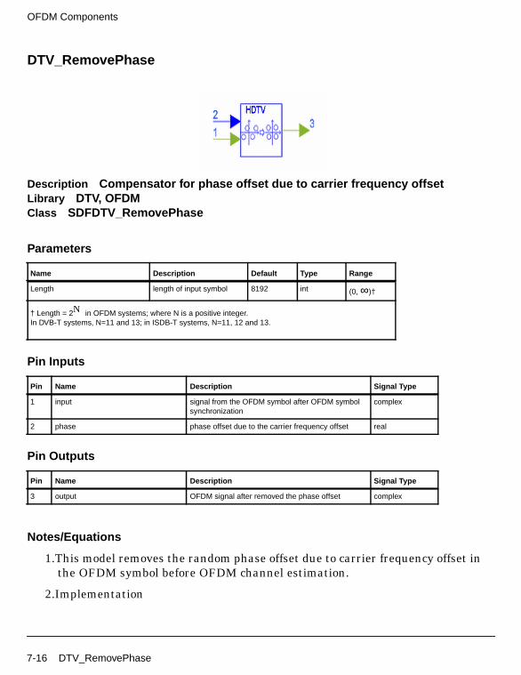
OFDM Components
DTV_RemovePhase
Description Compensator for phase offset due to carrier frequency offsetLibrary DTV, OFDMClass SDFDTV_RemovePhase
Parameters
Pin Inputs
Pin Outputs
Notes/Equations
1.This model removes the random phase offset due to carrier frequency offset inthe OFDM symbol before OFDM channel estimation.
2.Implementation
Name Description Default Type Range
Length length of input symbol 8192 int (0, ∞)†
† Length = 2N in OFDM systems; where N is a positive integer.In DVB-T systems, N=11 and 13; in ISDB-T systems, N=11, 12 and 13.
Pin Name Description Signal Type
1 input signal from the OFDM symbol after OFDM symbolsynchronization
complex
2 phase phase offset due to the carrier frequency offset real
Pin Name Description Signal Type
3 output OFDM signal after removed the phase offset complex
7-16 DTV_RemovePhase

Assume x(0), x(1), ... , x(N−1) are the received signal after OFDMsynchronization. The phase Φ is the detected phase offset due to the carrierfrequency offset in DTV_LoadFFTBuff model. The phase removed OFDM signaly(0), y(1), ... , y(N−1) is:
References
[1]J.J. van de Beek, M. Sandell, and P.O.Borjesson, On Synchronization in OFDMSystems Using the Cyclic Prefix, in Proceedings of Radio VetenskapligKonferens (REVK’96), pp.663-667, Lulea Sweden, June 1996
[2] ARIB-JAPAN, Terrestrial Integrated Services Digital Broadcasting (ISDB-T);Specification of Channel Coding, Framing Structure and Modulation,Sept.1998.
[3] ETSI, Digital Video Broadcasting (DVB); Framing structure, channel codingand modulation for digital terrestrial television. EN300 744 v1.2.1, EuropeanTelecommunication Standard, July 1999.
y i( ) x i( )ej2πΦi
N-----------------–
=
DTV_RemovePhase 7-17

OFDM Components
7-18

Chapter 8: Test Components
8-1

Test Components
DTV_BER
Description Bit error rate for ISDB-T and DVB-TLibrary DTV, TestClass SDFDTV_BER
Parameters
Pin Inputs
Pin Outputs
Notes/Equations
1. This model measures the input signal bit error rate.
Each firing, 1 token at pin ber is produced when Length×8 tokens are consumed(note that Length is bytes, while test and ref are bits).
2. If input test bit is ti, input reference bit is ri, the model calculates the error rateafter Delay according to the following example.
Name Description Default Type Range
Length length of input byte block 188 int [1, ∞)
Delay delay of byte blocks 512 int [0, ∞)
Pin Name Description Signal Type
1 test test input bit int
2 ref reference input bit int
Pin Name Description Signal Type
3 ber bit error rate real
8-2 DTV_BER

count=0;err =0;rate =0;if (count>Delay)
for (i=0;i<Length*8;i++) = test%i;
= ref%i;
= &1;
= &1;
if ( != )
err = err+1;
count++;if (count>Delay)
rate = err/((count-Delay)*length*8);BER%(0) <<rate;
ti
ri
ti ti
ri ri
ti ri
DTV_BER 8-3

Test Components
DTV_PowerMeasure
Description Average power measurementLibrary DTV, Test
Parameters
Pin Inputs
Pin Outputs
Notes/Equations
1. This subnetwork model measures the average power of the input signals.
The schematic for this subnetwork is shown in Figure 8-1.
Name Description Default Sym Type Range
BlockSize number of particles in ablock
16 m int [1, ∞)
Pin Name Description Signal Type
1 input input signal real
Pin Name Description Signal Type
2 Ave_P average power of all input signals real
3 B_P average power of input signals in a block real
8-4 DTV_PowerMeasure

Figure 8-1. DTV_PowerMeasure Schematic
2. Each firing, 1 token at B_P and Avg_P are produced when m input tokens areconsumed.
If input signal s(t)= x(t) + jy(t),
average signal power
for discrete signals
For B_P out, b − a = m; for Avg_P, a = 0, b = current input points.
P x2 t( ) y2 t( )+( ) tda
b
∫=
P
x2 n( ) y2 n( )+( )n a=
b
∑b a–
----------------------------------------------------=
DTV_PowerMeasure 8-5

Test Components
8-6
Chapter 9: DVB-H System Design Examples
IntroductionDVB-H design examples can be accessed from the ADS Main window File > ExampleProject > DTV. Schematics and simulation results for designs in DTV_DVBH_prj aredescribed in this chapter.
Hierarchical system design:
• DTV_DVBH_Demo_Hierarchical.dsn
Non-hierarchical system design:
• DTV_DVBH_Demo_Non-Hierarchical.dsn
Introduction 9-1

DVB-H System Design Examples
DTV DVB-H Hierarchical TransmissionDTV_DVBH_Demo_Hierarchical.dsn
Features
• Mode: 4k
• MappingMode: 64QAM
• Inner interleaving: in-depth
• High priority inner code rate: 2/3
• Low priority inner code rate: 5/6
• Guard interval: 1/16
• Oversampling ratio: 1
Description
This design is a hierarchical transmission example of DVB-H spectrum,constellation, and MER and BER measurements under an AWGN channel.
The schematic for this design is shown in Figure 9-1.
Parameters that can be changed by users are contained in VAR.
Figure 9-1. DTV_DVBH_Demo_Hierarchical Schematic
VAR1 contains delays needed for MER and BER measurements.
9-2 DTV DVB-H Hierarchical Transmission

For BER measurements after Reed-Solomon decoding, users should:
• Replace the Delay D3 component input signal LPBytes_BefCC withLPBytes_Uncoded.
• Replace IntToBits I1 input signal LPBytes_AftViterbi with LPBytes_Decoded.
• Replace DTV_BER and NumericSink BER_LP delay parameter settingsDelay_AftVB_LP*2 with Delay_AftDescramble_LP.
• Replace NumericSink BER_LP delay setting of 1e5 with a value greater than1e6.
For high priority stream BER measurements, users should replace all LP with HP.
Simulation Results
Simulation is under an AWGN channel with a carrier-to-noise ratio of 21.4 dB.Simulation results saved in DTV_DVBH_Demo_Hierarchical.dds are shown inFigure 9-2.
Figure 9-2. Simulation Results
Benchmark
• Hardware Platform: Pentium IV 2.26 GHz, 512 MB memory
• Software Platform: Windows 2000, ADS 2004A
• Simulation Time: approximately 1 minute
DTV DVB-H Hierarchical Transmission 9-3

DVB-H System Design Examples
References
[1]ETSI, Digital Video Broadcasting (DVB); Framing structure, channel codingand modulation for digital terrestrial television. EN300 744 v1.5.1, EuropeanTelecommunication Standard, November 2004.
9-4 DTV DVB-H Hierarchical Transmission

DTV DVB-H Non-Hierarchical TransmissionDTV_DVBH_Demo_Non_Hierarchical.dsn
Features
• Mode: 4k
• MappingMode: QPSK
• Inner interleaving: in-depth
• Inner code rate: 1/2
• Guard interval: 1/16
• Oversampling ratio: 1
Description
This design is a non-hierarchical transmission example of DVB-H spectrum,constellation, and MER and BER measurements under an AWGN channel.
The schematic for this design is shown in Figure 9-3.
Parameters that can be changed by users are contained in VAR.
DTV DVB-H Non-Hierarchical Transmission 9-5
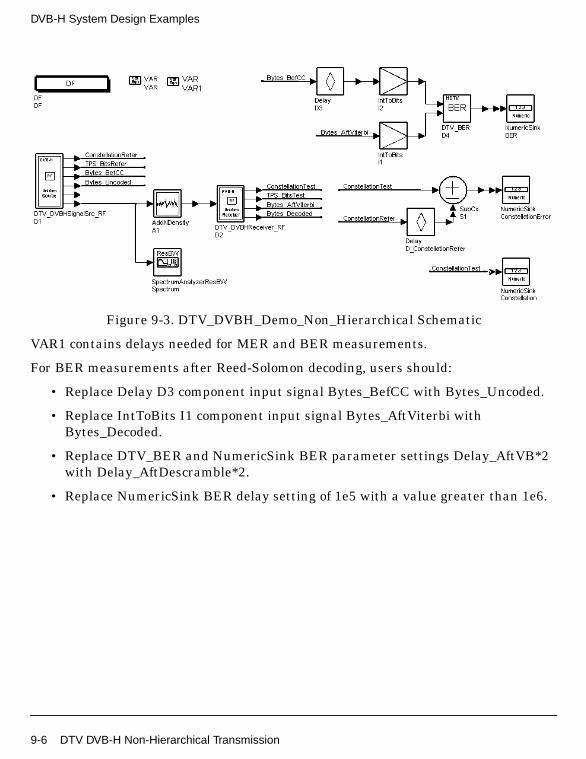
DVB-H System Design Examples
Figure 9-3. DTV_DVBH_Demo_Non_Hierarchical Schematic
VAR1 contains delays needed for MER and BER measurements.
For BER measurements after Reed-Solomon decoding, users should:
• Replace Delay D3 component input signal Bytes_BefCC with Bytes_Uncoded.
• Replace IntToBits I1 component input signal Bytes_AftViterbi withBytes_Decoded.
• Replace DTV_BER and NumericSink BER parameter settings Delay_AftVB*2with Delay_AftDescramble*2.
• Replace NumericSink BER delay setting of 1e5 with a value greater than 1e6.
9-6 DTV DVB-H Non-Hierarchical Transmission

Simulation Results
Simulation is under an AWGN channel with a carrier-to-noise ratio of 4.9 dB.Simulation results saved in DTV_DVBH_Demo_Non_Hierarchical.dds are shown inFigure 9-4.
Figure 9-4. Simulation Results
Benchmark
• Hardware Platform: Pentium IV 2.26 GHz, 512 MB memory
• Software Platform: Windows 2000, ADS 2004A
• Simulation Time: approximately 2 minutes
References
[1]ETSI, Digital Video Broadcasting (DVB); Framing structure, channel codingand modulation for digital terrestrial television. EN300 744 v1.5.1, EuropeanTelecommunication Standard, November 2004.
DTV DVB-H Non-Hierarchical Transmission 9-7

DVB-H System Design Examples
9-8 DTV DVB-H Non-Hierarchical Transmission
Chapter 10: DVB-T System Design Examples
IntroductionDVB-T design examples can be accessed from the ADS Main window File > ExampleProject > DTV. Schematics and simulation results for the following projects aredescribed in this chapter.
DTV_DVBOFDM_prj
• DsnDTV_DVBOFDM_16QAM.dsn
• DsnDTV_DVBOFDM_64QAM.dsn
• DsnDTV_DVBOFDM_PALInterference.dsn
DTV_DVBSystem_prj
• DsnDTV_DVBSystem_16QAM.dsn
• DsnDTV_DVBSystem_Hier64QAM.dsn
• DsnDTV_DVBOFDM_16QAM_BER.dsn
Introduction 10-1

DVB-T System Design Examples
DTV OFDM
OFDM 16-QAM Modulation and Demodulation in DVB-T Systems
DTV_DVBOFDM_prj Design Name
DsnDTV_DVBOFDM_16QAM.dsn
Features
• 16-QAM modulation and demodulation
• TDMA multipath fading channel with Doppler shift. The type of multipath canbe selected; Doppler shift can be determined by the mobile speed setting.
• Comparison of DVB and TDMA channel system performance
Description
This example design provides modulation, transmission, and demodulation via aTDMA channel with Doppler shift and DVB channel. Modulation mapping is16-QAM; the guard interval ratio is 1/16.
After 16-QAM data mapping, OFDM symbols are formed by adding TPS data andpilots. 2048-point inverse FFT (IFFT) is performed. After inserting the guardinterval, the complex signal is transmitted; the transmitted signal length is2048+guard interval.
In the receiver, the FFT starting point is determined by the autocorrection function ofthe received signal. After FFT, the transmitted signal is recovered by the frequencyequalizer. According to the DVB-T, the mapped data is received. Data is recovered bythe 16-QAM demodulator.
Performance can be viewed in data display files such DsnDTV_DVBOFDM_16QAMand DsnDTV_DVBOFDM_16QAM_EVM.
Schematics
Figure 10-1 shows the schematic for this design. Three subnetworks are used in thisdesign; they are shown in Figure 10-2 through Figure 10-4.
10-2 DTV OFDM

Figure 10-1. DTV_DVBOFDM_16QAM.dsn
Figure 10-2. sub_DVBOFDM_Mod.dsn
Figure 10-3. sub_DVBOFDM_Demod.dsn
DTV OFDM 10-3

DVB-T System Design Examples
Figure 10-4. sub_TDMAChannel
Specifications
Notes
1. In this example, the guard interval ratio is 1/16, so the guard interval is 128.(According to DVB-T, in the 2K mode the guard interval is 64, 128, 256, or 512,which corresponds to 1/32, 1/16, 1/8, or 1/4 guard interval ratio, respectively.)
2. All parameters are related to the guard interval (except TDMA channelparameters). If the guard interval is changed, parameters will be changed tothe corresponding values.
Symbol (Model) Specification (Parameter) Simulation Type Value
RxSpectrum Stop ADS Ptolemy 224*(2048+128)/2048*2 µsec
RxSignal Stop ADS Ptolemy 224*(2048+128)/2048 µsec
PropNADCtdma Type ADS Ptolemy TwoPath
PropNADCtdma Pathloss ADS Ptolemy No
PropNADCtdma Env ADS Ptolemy TypicalSuburban
PropNADCtdma Delay ADS Ptolemy 0.5 µsec
PropNADCtdma Test ADS Ptolemy Tap1
AntMobile Vx ADS Ptolemy 100.0 km/hr
AntMobile Vy ADS Ptolemy 0.0 km/hr
10-4 DTV OFDM

3. The TDMA channel condition varies according to channel parametermodification. Parameters include Type, Pathloss, Env, Delay, and Test in thePropNADCtdma model, and Vx and Vy in the AntMobile model.
Simulation Results
Figure 10-5 shows the magnitude of ML function of received signal used to find theFFT start. The maximum value appears in every (2048+128) points, the point of themaximum magnitude value is the FFT start.
Figure 10-6 shows the received constellation after OFDM demodulation via DVBchannel. Results show the hard decision before the 16-QAM demodulation is correct
Figure 10-5. ML Magnitude
Figure 10-6. Received Constellation After OFDM Demodulation
DTV OFDM 10-5

DVB-T System Design Examples
Figure 10-7 shows the received constellation after OFDM demodulation via TDMAchannel. Results show OFDM system performance
Figure 10-8 shows the spectrum of the wireless channel signal; center frequency is474 MHz.
Figure 10-9 shows the adjacent-channel power ratio. The equation is:ACPR=acpr_vr(DsnDTV_DVBOFDM_16QAM..RxSignal,50.0,-3.9MHz,3.9MHz,-12MHz,-4.25MHz,4.25MHz,12MHz)
Figure 10-7. Received Constellation after OFDM Demodulation
Figure 10-8. Spectrum of Signal Received from Wireless Channel
Figure 10-9. Adjacent-Channel Power Ratio
10-6 DTV OFDM

Figure 10-10 shows the relative magnitude error, which is defined as:EVM=mag(DsnDTV_DVBOFDM_16QAM..Rx16QAM1-DsnDTV_DVBOFDM_16QAM.Tx16QAM)/mean(mag(DsnDTV_DVBOFDM_16QAM..Tx16QAM)).
Figure 10-11 shows the EVM histogram, which shows most EVM < 0.1. EVMhist isdefined as: EVMhist=histogram(EVM,1001,0.0,1.0)
Figure 10-10. Relative Magnitude Error
Figure 10-11. EVM Histogram
Benchmark
• Hardware Platform: Pentium II 200 MHz, 96 MB memory
• Software Platform: Windows NT 4.0 Workstation, ADS 1.3
• Data Points: 10 OFDM symbols
• Simulation Time: 34 seconds
References
[1]ETSI, “Digital Video Broadcasting (DVB); Framing structure, channel codingand modulation for digital terrestrial television.” EN300 744 v1.2.1, EuropeanTelecommunication Standard, July 1999.
DTV OFDM 10-7

DVB-T System Design Examples
OFDM 64-QAM Modulation and Demodulation in DVB-T Systems
DTV_DVBOFDM_prj Design Name
DsnDTV_DVBOFDM_64QAM.dsn
Features
• 64-QAM modulation and demodulation
• TDMA multipath fading channel with Doppler shift. The type of multipath canbe selected; Doppler shift can be determined by the mobile speed setting.
• DVB and TDMA channel performance comparison
Description
This example design provides modulation, transmission and demodulation via aTDMA channel with Doppler shift and DVB channel. Modulation mapping is64-QAM; the guard interval ratio is 1/16.
After 64-QAM data mapping, OFDM symbols are formed by adding TPS data andpilots. 2048-point inverse FFT (IFFT) is performed. After inserting the guardinterval, the complex signal is transmitted. Transmitted signal length is 2048+guardinterval.
In the receiver, the FFT starting point is determined by the autocorrection function ofthe received signal. After FFT, the transmitted signal is recovered by the frequencyequalizer. According to the DVB-T, the mapped data is received. Data is recovered bythe 64-QAM demodulator.
Performance can be viewed in the data display files such asDsnDTV_DVBOFDM_64QAM and DsnDTV_DVBOFDM_64QAM_EVM.
Schematics
Figure 10-12 shows the schematic for this design. Three subnetworks are used in thisdesign; they are shown in Figure 10-13 through Figure 10-15.
10-8 DTV OFDM

Figure 10-12. DTV_DVBOFDM_64QAM.dsn
Figure 10-13. sub_DVBOFDM_Mod.dsn
Figure 10-14. sub_DVBOFDM_Demod.dsn
DTV OFDM 10-9

DVB-T System Design Examples
Figure 10-15. sub_TDMAChannel.dsn
Specifications
Notes
1. In this example, the guard interval ratio is 1/16, so the guard interval is 128.(According to DVB-T, in the 2K mode the guard interval is 64, 128, 256, or 512,which corresponds to 1/32, 1/16, 1/8, or 1/4 guard interval ratio, respectively.)
2. All parameters are related to the guard interval (except TDMA channelparameters). If the guard interval is changed, parameters will be changed tothe corresponding values.
Symbol (Model) Specification (Parameter) Simulation Type Value
RxSpectrum Stop ADS Ptolemy 224*(2048+128)/2048*2
µsec
RxSignal Stop ADS Ptolemy 224*(2048+128)/2048 µsec
PropNADCtdma Type ADS Ptolemy TwoPath
PropNADCtdma Pathloss ADS Ptolemy No
PropNADCtdma Env ADS Ptolemy TypicalSuburban
PropNADCtdma Delay ADS Ptolemy 2.5 µsec
PropNADCtdma Test ADS Ptolemy Tap1
AntMobile Vx ADS Ptolemy 30.0 km/hr
AntMobile Vy ADS Ptolemy 0.0 km/hr
10-10 DTV OFDM

3. The TDMA channel condition varies according to channel parametermodification. Parameters include Type, Pathloss, Env, Delay, and Test in thePropNADCtdma model, and Vx and Vy in the AntMobile model.
Simulation Results
Figure 10-16 shows the magnitude of the ML function of the received signal used tofind the FFT start point. The maximum value appears in every (2048+128) points,the point of the maximum magnitude value is the starting point of the FFT.
Figure 10-17 shows the received constellation after OFDM demodulation via TDMAchannel. Results show the hard decision before the 64-QAM demodulation is correct.
Figure 10-16. Maximum Likelihood Magnitude
Figure 10-17. Received Constellation After OFDM Demodulationvia TDMA Channel
DTV OFDM 10-11

DVB-T System Design Examples
Figure 10-18 shows the received constellation after OFDM demodulation via DVBchannel. Results show OFDM system performance.
Figure 10-19 shows the spectrum of wireless channel signal received. Centerfrequency is 474 MHz.
Figure 10-20 shows adjacent-channel power ratio. The equation is:ACPR=acpr_vr(DsnDTV_DVBOFDM_64QAM..RxSignal,50.0,-3.9MHz,3.9MHz,-12MHz,-4.25MHz,4.25MHz,12MHz).
Figure 10-18. Received Constellation After OFDM DemodulationVia DVB Channel
Figure 10-19. Spectrum of Wireless Channel Signal Received
Figure 10-20. Adjacent-Channel Power Ratio
10-12 DTV OFDM

Figure 10-21 shows the relative magnitude error, which is defined as:EVM=mag(DsnDTV_DVBOFDM_64QAM..Rx64QAM1-DsnDTV_DVBOFDM_64QAM..Tx64QAM)/mean(mag(DsnDTV_DVBOFDM_64QAM..Tx64QAM))
Figure 10-22 shows the EVM histogram, which shows most EVM < 0.1. The EVMhistis defined as: EVMhist=histogram(EVM,1001,0.0,1.0)
Figure 10-21. Relative Magnitude Error
Figure 10-22. EVM Histogram
DTV OFDM 10-13

DVB-T System Design Examples
Benchmark
• Hardware Platform: Pentium II 200 MHz, 96 MB memory
• Software Platform: Windows NT 4.0 Workstation, ADS 1.3
• Data Points: 10 OFDM symbols
• Simulation Time: 34 seconds
References
[1]ETSI, “Digital Video Broadcasting (DVB); Framing structure, channel codingand modulation for digital terrestrial television.” EN300 744 v1.2.1, EuropeanTelecommunication Standard, July 1999.
10-14 DTV OFDM
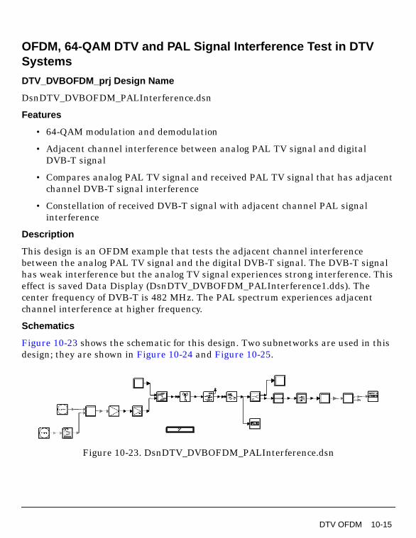
OFDM, 64-QAM DTV and PAL Signal Interference Test in DTVSystems
DTV_DVBOFDM_prj Design Name
DsnDTV_DVBOFDM_PALInterference.dsn
Features
• 64-QAM modulation and demodulation
• Adjacent channel interference between analog PAL TV signal and digitalDVB-T signal
• Compares analog PAL TV signal and received PAL TV signal that has adjacentchannel DVB-T signal interference
• Constellation of received DVB-T signal with adjacent channel PAL signalinterference
Description
This design is an OFDM example that tests the adjacent channel interferencebetween the analog PAL TV signal and the digital DVB-T signal. The DVB-T signalhas weak interference but the analog TV signal experiences strong interference. Thiseffect is saved Data Display (DsnDTV_DVBOFDM_PALInterference1.dds). Thecenter frequency of DVB-T is 482 MHz. The PAL spectrum experiences adjacentchannel interference at higher frequency.
Schematics
Figure 10-23 shows the schematic for this design. Two subnetworks are used in thisdesign; they are shown in Figure 10-24 and Figure 10-25.
Figure 10-23. DsnDTV_DVBOFDM_PALInterference.dsn
DTV OFDM 10-15

DVB-T System Design Examples
Figure 10-24. sub_OFDM_Mod.dsn
Figure 10-25. sub_DVBOFDM_Demod.dsn
Specifications
Notes
1. In this example, the guard interval ratio is 1/16, so the guard interval is 128.(According to DVB-T, in the 2K mode the guard interval is 64, 128, 256, or 512,which corresponds to 1/32, 1/16, 1/8, or 1/4 guard interval ratio, respectively.)
2. Except for TDMA channel parameters, all parameters are related to the guardinterval. If the guard interval is changed, they will be changed to thecorresponding values.
Specification (Parameter) Simulation Type Value
IFFTSize ADS Ptolemy 2048*4
FFTSize ADS Ptolemy 2048*4
GuardInterval ADS Ptolemy 128*4
IFFTOrder ADS Ptolemy 13
FFTOrder ADS Ptolemy 13
MaxDelay ADS Ptolemy 2048*4
10-16 DTV OFDM

3. The TDMA channel condition varies according to channel parametermodification. Parameters include Type, Pathloss, Env, Delay, and Test in thePropNADCtdma model, and Vx and Vy in the AntMobile model.
Simulation Results
Figure 10-26 shows the ML (maximum likelihood) magnitude which shows themagnitude of ML function of the received signal used to find the FFT starting point.The maximum value appears in every 4*(2048+128) points; the maximum magnitudevalue is the FFT starting point.
Figure 10-27 shows the received QAM constellation after OFDM demodulation viaTDMA channel with adjacent band PAL signal interference.
Figure 10-26. Maximum Likelihood Magnitude
DTV OFDM 10-17

DVB-T System Design Examples
Figure 10-27. Received 64-QAM Constellation after OFDM DemodulationVia TDMA Channel
Figure 10-28. Spectrum of Signal Received from Wireless Channel
10-18 DTV OFDM

Figure 10-29. Comparison of PAL Video Input Signal and Output Signalwith Adjacent Band DVB-T Signal Interference
Benchmark
• Hardware Platform: Pentium II 200 MHz, 96 MB memory
• Software Platform: Windows NT 4.0 Workstation, ADS 1.3
• Data Points: 10 OFDM symbols
• Simulation Time: 2 hours
References
[1]ETSI, “Digital Video Broadcasting (DVB); Framing structure, channel codingand modulation for digital terrestrial television.” EN300 744 v1.2.1, EuropeanTelecommunication Standard, July 1999.
DTV OFDM 10-19

DVB-T System Design Examples
DTV DVB System
OFDM 16-QAM DVB-T System without Channel Coding BER
DTV_DVBSystem_prj Design Name
DsnDTV_DVBOFDM_16QAM_BER.dsn
Features
• 16-QAM modulation and demodulation
• Guard interval
• Displays include:ML (maximum likelihood) estimation for OFDM frame synchronization,Angle (phase offset due to carrier frequency) for OFDM carrier synchronization,TxBit, RxBit, and Rx16QAM
• BER performance test for Gaussian, Ricean, and Rayleigh channels
Description
This OFDM adaptation for DVB-T 2K mode design example tests the BER withoutchannel coding. Modulation mapping is 16-QAM; the guard interval ratio is 1/16.
Simulation results can be compared to those of DsnDTV_DVBSystem_16QAM.dsn,which tests the BER with channel coding and interleaving.
Schematics
Figure 10-30 shows the schematic for this design. Two subnetworks are used in thisdesign; they are shown in Figure 10-31 and Figure 10-32.
10-20 DTV DVB System

Figure 10-30. DsnDTV_DVBOFDM_16QAM_BER.dsn
Figure 10-31. sub_DVBOFDM_Mod.dsn
Figure 10-32. sub_DVBOFDM_Demod.dsn
DTV DVB System 10-21

DVB-T System Design Examples
Specifications
Notes
1. In this example, the guard interval ratio is 1/16, so the guard interval is 128.(According to DVB-T, in the 2K mode the guard interval is 64, 128, 256, or 512,which corresponds to 1/32, 1/16, 1/8, or 1/4 guard interval ratio, respectively.)
2. This design can be used for three different simulations: Gaussian channel,Ricean channel (F1) and Rayleigh channel.
Simulation Results
• Additive white Gaussian noise was added to set the carrier-to-noise (CN) ratioat the input of the receiver. Figure 10-33 shows the received constellation afterOFDM demodulation when the CN is 15dB and 25dB in Gaussian channelsimulation. The results show the higher CN is better than the lower.
Figure 10-34 shows the BER at different CN.
Symbol (Model) Specification (Parameter) Simulation Type Value
Carriers ADS Ptolemy 1705
Data ADS Ptolemy 1512
IFFTSize ADS Ptolemy 2048
FFTSize ADS Ptolemy 2048
Guard ADS Ptolemy 128
IFFTOrder ADS Ptolemy 11
FFTOrder ADS Ptolemy 11
MaxDelay ADS Ptolemy 2047
DTV_DVBChannel SampleTime ADS Ptolemy 224.0e-6/2048
10-22 DTV DVB System

Figure 10-33. Constellation of OFDM Demodulation Signalat Different CN
Figure 10-34. Gaussian Channel BER
DTV DVB System 10-23

DVB-T System Design Examples
• Ricean channel
Measurements of BER vs. CN were made using a Ricean channel simulator.The channel parameter is from DVB-T. In our DTV simulation system, thisRicean channel is simulated by sub_DVBChannel subnetwork, its parameterswere set as follows:
This simulation result was not included in this DTV package because of thelimitation of DTV package size. If users want to prove the BER performance ofthis channel, users can set the parameters above and run this design example.The simulation time is very long.
Figure 10-35 shows the received constellation after OFDM demodulation whenthe CN is 15dB and 25dB, respectively in the Ricean channel simulation. Theresults show the result of higher CN is better than that of lower CN.
Figure 10-36 shows the BER of different CN when the simulation channel isRicean channel.
Figure 10-35. Constellation of OFDM Demodulation Signal at Different CN
Symbol Specification Simulation Type Value
sub_DVBChannel NoiseGain ADS Ptolemy 5.45/exp(CN/10.0*ln(10))
DVBChannel ChannelModel ADS Ptolemy Fixed Reception F1
10-24 DTV DVB System

Figure 10-36. Ricean Channel BER
• Rayleigh channel
Measurements of BER vs. CN were made using a Rayleigh channel simulator.The channel parameter is from DVB-T. In our DTV simulation system, thisRicean channel is simulated by sub_DVBChannel subnetwork, its parameterswere set as follows:
This simulation result was not included in this DTV package because of thelimitation of DTV package size. If users want to prove the BER performance ofthis channel, users can set the parameters above and run this design example.The simulation time is very long.
Figure 10-37 shows the received constellation after OFDM demodulation whenthe CN is 15dB and 25dB. The results show the higher CN is better than thelower.
Figure 10-38 shows the BER of different CN.
Symbol Specification Simulation Type Value
sub_DVBChannel NoiseGain ADS Ptolemy 0.45/exp(CN/10.0*ln(10))
DVBChannel ChannelModel ADS Ptolemy Portable Reception P1
DTV DVB System 10-25

DVB-T System Design Examples
Figure 10-39 shows BERs of the three channels; the AWGN channel is the best.
Figure 10-37. Constellation of OFDM Demodulation Signal at Different CN
Figure 10-38. Rayleigh Channel BER
10-26 DTV DVB System

Figure 10-39. Gaussian, Ricean, and Rayleigh Simulation Channel BERs
Benchmark
• Hardware Platform: Pentium II 200 MHz, 128 MB memory
• Software Platform: Windows NT 4.0 Workstation, ADS 1.3
• Data Points: 200 OFDM symbols
• Simulation Time: Approximately one hour and 38 minutes for each channelmodel
References
[1]ETSI, “Digital Video Broadcasting (DVB); Framing structure, channel codingand modulation for digital terrestrial television.” EN300 744 v1.2.1, EuropeanTelecommunication Standard, July 1999.
DTV DVB System 10-27

DVB-T System Design Examples
16-QAM DVB-T System Design
DTV_DVBSystem_prj Design Name
DsnDTV_DVBSystem_16QAM.dsn
Features
• 16-QAM modulation and demodulation
• 2K mode OFDM adaptation
• Channel coding and decoding, including Reed-Solomon, 1/2 puncturedconvolutional coding
• Inner and outer interleaving
• BER performance test for Gaussian, Ricean, and Rayleigh channels
Description
This DVB-T system design includes inner and outer interleaving, Reed-Solomon andconvolutional coding, and full OFDM adaptation. Modulation modes and code ratesare uniform 16-QAM and 1/2, respectively. In the OFDM adaptation, the full systemdesign works in 2K mode. The IFFT/ FFT is 2048; the Guard interval is 1/16 the IFFTsize. Simulation channels are Gaussian, Ricean, and Rayleigh.
The byte in transmitter and receiver, the BER of the three simulation channels areshown in the simulation results. The BER of the channels in this design arecompared to the DVB system without channel coding and interleaving in theDsnDTV_DVBOFDM_16QAM_BER.dsn.
Schematics
Figure 10-40 shows the schematic for this design. Four subnetworks are used in thisdesign; they are shown in Figure 10-41 through Figure 10-44.
10-28 DTV DVB System

Figure 10-40. DTV_DVBSystem_16QAM.dsn
Figure 10-41. sub_DVBOFDM_Mod.dsn
Figure 10-42. sub_DVBOFDM_Demod.dsn
DTV DVB System 10-29

DVB-T System Design Examples
Figure 10-43. sub_DVBInnerInterlv.dsn
Figure 10-44. sub_DVBInnerDeinterlv.dsn
10-30 DTV DVB System

Specifications
Notes
1. The propagation channel model used in this example is a standard terrestrialtelevision propagation channel as defined in the DVB-T specification.
2. The DelayByte parameter of the punctured convolutional decoder(DTV_PuncConvDecoder model) is used to adjust delays caused by OFDMdemodulation (which is one OFDM symbol) and one additional OFDM symboldelay (which corresponds to the DTV_DVBSymDeinterlv4b model) because thismodel uses an even number of OFDM symbols.
Specification (Parameter) Simulation Type Value
Carriers ADS Ptolemy 1705
Data ADS Ptolemy 1512
IFFTSize ADS Ptolemy 2048
FFTSize ADS Ptolemy 2048
Guard ADS Ptolemy 128
IFFTOrder ADS Ptolemy 11
FFTOrder ADS Ptolemy 11
MaxDelay ADS Ptolemy 2047
Ru ADS Ptolemy 0.9
DTV DVB System 10-31

DVB-T System Design Examples
Simulation Results
• AWGN Channel
Additive white Gaussian noise was added to set the carrier-to-noise (CN) ratioat the receiver input.
Figure 10-45 shows the transmitted and received TSP data when the CN ratiois 5dB and 8dB in Gaussian channel simulation. In Figure 10-45, the firstcolumn is the received TSP of CN=5dB; the second column is the received TSPof CN=8dB; the last line is the transmitted TSP. Compared to TxTSP, the firstline has more errors than the second line.
Figure 10-45. Compare RxTSP with TxTSP with different CN
The BERs of the full system and OFDM system (without channel coding inDsnDTV_DVBOFDM_16QAM_BER.dsn) are shown in Figure 10-46. Channelcoding gain is approximately 8.5dB at 0.001 BER.
10-32 DTV DVB System

According to DVB-T, in 16-QAM modulation, code rate is 1/2, and Gaussianchannel model condition, the required CN for BER=0.0002 after Viterbi QEFand Reed-Solomon coding is 8.8dB. In Figure 10-46, CN is approximately 8.8dBfor BER=0.0002. The simulation results shows this design is correct in theGaussian channel.
Figure 10-46. Gaussian Channel BER(solid line = full system;
dash line = DsnDTV_DVBOFDM_16QAM_BER.dsn)
DTV DVB System 10-33

DVB-T System Design Examples
• Ricean channel
Measurements of BER vs. CN were made using a Ricean channel simulator.The channel parameter is from DVB-T. In our DTV simulation system, thisRicean channel is simulated by sub_DVBChannel subnetwork, its parameterswere set as follows:
Figure 10-47 show the transmitted and received TSP data when CN ratio is5dB and 8dB in the Ricean channel simulation. The first column is the receivedTSP of CN=5dB, the second column is the received TSP of CN=8dB; the lastcolumn is the transmitted TSP. Compared to TxTSP, the first line has moreerrors than the second line.
Figure 10-47. Compare RxTSP with TxTSP with Different CN
Symbol Specification Simulation Type Value
sub_DVBChannel NoiseGain ADS Ptolemy 5.45/exp(CN/10.0*ln(10))
DVBChannel ChannelModel ADS Ptolemy Fixed Reception F1
10-34 DTV DVB System

The BERs of the full system and OFDM system (without channel coding inDsnDTV_DVBOFDM_16QAM_BER.dsn) are shown in Figure 10-48. Channelcoding gain is approximately 10dB at 0.001 BER. According to DVB-T, in16-QAM modulation, code rate is 1/2, and Gaussian channel model condition,the required CN for BER=0.0002 after Viterbi QEF after Reed-Solomon codingis 9.6dB. In Figure 10-48, CN is approximately 9.6dB for BER=0.0002. Thesimulation results shows this design is correct in the Ricean channel.
Figure 10-48. Ricean Channel BER(solid line = full system;
dash line = DsnDTV_DVBOFDM_16QAM_BER.dsn)
DTV DVB System 10-35

DVB-T System Design Examples
• Rayleigh channel
Measurements of BER vs. CN were made using a Rayleigh channel simulator.The channel parameter is from DVB-T. In our DTV simulation system, thisRicean channel is simulated by sub_DVBChannel subnetwork, its parameterswere set as follows:
This simulation result was not included in this DTV package because of thelimitation of DTV package size. To prove the BER performance of this channel,set the parameters and run this design example; simulation time is very long.
Figure 10-49 shows the transmitted and received TSP data when CN is 5dBand 8dB in Rayleigh channel simulation. The first column is the received TSP ofCN=5dB, the second column is the received TSP of CN=8dB; the last column isthe transmitted TSP. Compared to the TxTSP, the first column shows manyerrors, while the second column has fewer errors.
Symbol Specification Simulation Type Value
sub_DVBChannel NoiseGain ADS Ptolemy 0.45/exp(CN/10.0*ln(10))
DVBChannel ChannelModel ADS Ptolemy Portable Reception P1
10-36 DTV DVB System

Figure 10-49. Compare RxTSP with TxTSP with different CN
The BERs of the full system and OFDM system (without channel coding inDsnDTV_DVBOFDM_16QAM_BER.dsn) are shown in Figure 10-50. Channelcoding gain is approximately 12.0dB at 0.001 BER. According to the DVB-T, in16-QAM modulation, code rate is 1/2, and Rayleigh channel model condition,the required CN for BER=0.0002 after Viterbi QEF after Reed-Solomon codingis 11.2dB. In Figure 10-50, CN is approximately 13.8dB for BER=0.0002.
DTV DVB System 10-37

DVB-T System Design Examples
Figure 10-50. Rayleigh Channel BER(solid line = full system;
dotted line = DsnDTV_DVBOFDM_16QAM_BER.dsn)
The simulated system performance in DVB-T Appendix A is obtained at Perfectchannel estimation and without phase noise condition; the performance in DVB-TTable A.1 is the best performance. In our simulation, channel estimation is notperfect because of noise (the channel estimation may have some distortion).Moreover, the frequency equalizer may enhance noise power because of fading.Therefore, the 2.6dB difference between our simulation and DVB-T is suitablebecause there is no fading in Gaussian and Ricean channels.
Figure 10-51 is shown the BERs of all the three simulation channels. FromFigure 10-51, the performance of the Gaussian channel is the best, then the Riceanchannel, the performance of the Rayleigh channel is the worst.
10-38 DTV DVB System
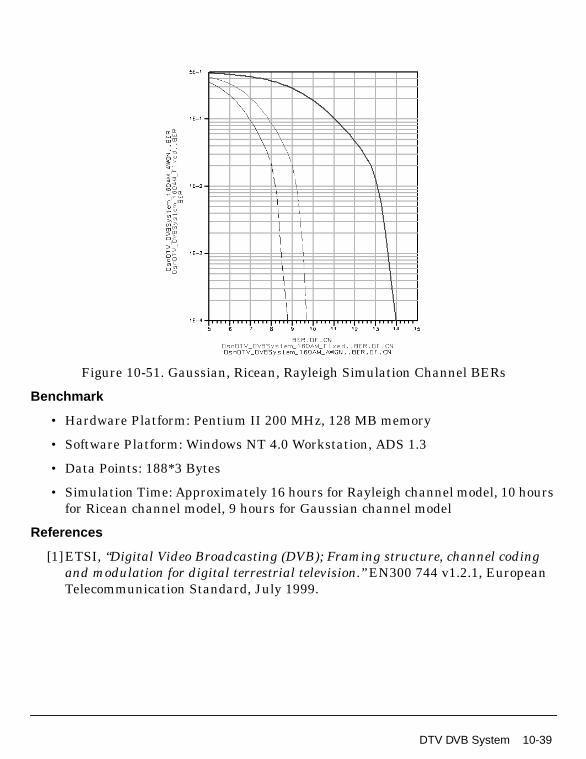
Figure 10-51. Gaussian, Ricean, Rayleigh Simulation Channel BERs
Benchmark
• Hardware Platform: Pentium II 200 MHz, 128 MB memory
• Software Platform: Windows NT 4.0 Workstation, ADS 1.3
• Data Points: 188*3 Bytes
• Simulation Time: Approximately 16 hours for Rayleigh channel model, 10 hoursfor Ricean channel model, 9 hours for Gaussian channel model
References
[1]ETSI, “Digital Video Broadcasting (DVB); Framing structure, channel codingand modulation for digital terrestrial television.” EN300 744 v1.2.1, EuropeanTelecommunication Standard, July 1999.
DTV DVB System 10-39

DVB-T System Design Examples
Hierarchical 64-QAM DVB-T System Design
DTV_DVBSystem_prj Design Name
DsnDTV_DVBSystem_Hier64QAM.dsn
Features
• Channel coding and decoding, including Reed-Solomon coding, puncturedconvolutional coding
• 2K mode OFDM adaptation
• Inner and outer interleaving
• Hierarchical 64-QAM modulation and demodulation
Description
This is a hierarchical DVB-T system design example. It includes inner and outerinterleaving, Reed-Solomon and convolutional coding and full OFDM adaptationsystem. The modulation mode is hierarchical 64-QAM. Code rates for HP level(r1)and LP level(r2) are 1/2 and 5/6, respectively. In the OFDM adaptation, the fullsystem design works in 8K mode. The IFFT/ FFT size is 8192 and the Guard intervalis 1/16 of IFFT size. The simulation channel is the DVB channel. The byte intransmitter and receiver are shown in the simulation results.
Schematics
Figure 10-52 shows the schematic for this design. Four subnetworks are used in thisdesign; they are shown in Figure 10-53 through Figure 10-56.
10-40 DTV DVB System

Figure 10-52. DsnDTV_DVBSystem_Hier64QAM.dsn
Figure 10-53. sub_DVBOFDM_Mod.dsn
Figure 10-54. sub_DVBOFDM_Demod.dsn
DTV DVB System 10-41

DVB-T System Design Examples
Figure 10-55. sub_DVBHier_InnerInterlv.dsn
Figure 10-56. sub_DVBHier_InnerDeinterlv.dsn
10-42 DTV DVB System

Specifications
Notes
1. The propagation channel model used in this example is a standard terrestrialtelevision propagation channel which is defined in the DVB-T specification.
2. The DelayByte parameter of the punctured convolutional decoder(DTV_PuncConvDecoder model) is used to adjust delays caused by OFDMdemodulation (which is one OFDM symbol) and one additional OFDM symboldelay (which corresponds to the DTV_DVBSymDeinterlv6b model) because thismodel uses an even number of OFDM symbols.
Simulation Results
Figure 10-57 shows the transmitted HP (high priority) TSP data and the received HPTSP data. Figure 10-58 shows the transmitted LP (low priority) TSP data and thereceived LP low data.
Specification (Parameter) Simulation Type Value
Carriers ADS Ptolemy 6817
Data ADS Ptolemy 6048
IFFTSize ADS Ptolemy 8192
FFTSize ADS Ptolemy 8192
Guard ADS Ptolemy 512
IFFTOrder ADS Ptolemy 13
FFTOrder ADS Ptolemy 13
MaxDelay ADS Ptolemy 8192
Ru ADS Ptolemy 0.9
DTV DVB System 10-43

DVB-T System Design Examples
Figure 10-57. Compare HP RxTSP with HP TxTSP
10-44 DTV DVB System

Figure 10-58. Compare LP RxTSP with LP TxTSP
Benchmark
• Hardware Platform: Pentium II 200 MHz, 128 MB memory
• Software Platform: Windows NT 4.0 Workstation, ADS 1.3
• Data Points: 188*3 Bytes
• Simulation Time: Approximately 1.5 hours
References
[1]ETSI, “Digital Video Broadcasting (DVB); Framing structure, channel codingand modulation for digital terrestrial television.” EN300 744 v1.2.1, EuropeanTelecommunication Standard, July 1999.
DTV DVB System 10-45

DVB-T System Design Examples
10-46 DTV DVB System

Chapter 11: DVB-T Receiver DesignExamples
IntroductionDVB-T receiver design examples can be accessed from the ADS Main window File >Example Project > DTV. Schematics and simulation results for designs inDTV_DVBT_Rx_prj are described in this chapter.
Receiver minimum input level sensitivity:
DTV_DVBT_Rx_Sensitivity_Option1.dsnDTV_DVBT_Rx_Sensitivity_Option2.dsn
AWGN performance:
DTV_DVBT_Rx_AWGN_Option1.dsnDTV_DVBT_Rx_AWGN_Option2.dsn
Protection ratio for co-channel PAL analog TV:
DTV_DVBT_Rx_PAL_Cochannel_Option1.dsnDTV_DVBT_Rx_PAL_Cochannel_Option2.dsn
Protection ratio for adjacent channel PAL analog TV:
DTV_DVBT_Rx_PAL_Adj_Option1.dsnDTV_DVBT_Rx_PAL_Adjl_Option2.dsn
Protection ratio for image channel PAL analog TV:
DTV_DVBT_Rx_PAL_image_Option1.dsnDTV_DVBT_Rx_PAL_imagel_Option2.dsn
Short delay echo performance:
DTV_DVBT_Rx_ShortDelay_Option1.dsnDTV_DVBT_Rx_ShortDelay_Option2.dsn
Long delay echo performance:
DTV_DVBT_Rx_LongDelay_Option1.dsnDTV_DVBT_Rx_LongDelay_Option2.dsn
Introduction 11-1

DVB-T Receiver Design Examples
Single 0dB echo performance:
DTV_DVBT_Rx_SingleEcho_Option1.dsnDTV_DVBT_Rx_SingleEcho_Option2.dsn
Immunity to impulse interference:
DTV_DVBT_Rx_Impulse_Option1.dsnDTV_DVBT_Rx_Impulse_Option2.dsn
Multipath performance:
DTV_DVBT_Rx_Rayleigh_Option1.dsnDTV_DVBT_Rx_Rayleigh_Option2.dsnDTV_DVBT_Rx_Ricean_Option1.dsnDTV_DVBT_Rx_Ricean_Option2.dsn
11-2 Introduction

DVB-T AWGN PerformanceDTV_DVBT_Rx_AWGN_Option1.dsnDTV_DVBT_Rx_AWGN_Option2.dsn
Features: Option 1 Design
• 2K mode
• 64-QAM mapping
• 2/3 coding rate
• 1/32 guard interval
• Signal_Generation_VARs and RF_Channel_Measurement_VARs parameterscan be changed by the user
Features: Option 2 Design
• 2K mode
• 16-QAM mapping
• 3/4 coding rate
• 1/32 guard interval
• Signal_Generation_VARs and RF_Channel_Measurement_VARs parameterscan be changed by the user
Description
These designs measure the performance of a DVB-T receiver with AWGN. BER ismeasured after Viterbi decoding.
The schematic is shown in Figure 11-1.
DVB-T AWGN Performance 11-3
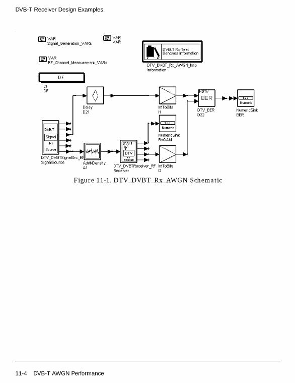
DVB-T Receiver Design Examples
.
Figure 11-1. DTV_DVBT_Rx_AWGN Schematic
11-4 DVB-T AWGN Performance

Simulation Results
For Option 1, an 18.3 dB carrier-to-noise ratio is used. Simulation results displayedin DTV_DVBT_Rx_AWGN_Option1.dds are shown in Figure 11-2. The demodulatedconstellations are shown in Figure 11-3.
Figure 11-2. BER for Option 1
Figure 11-3. Constellation for Option 1
For Option 2, a 13.8 dB carrier-to-noise ratio is used. Simulation results displayed inDTV_DVBT_Rx_AWGN_Option2.dds are shown in Figure 11-4. The demodulatedconstellation is shown in Figure 11-5.
Figure 11-4. BER for Option 2
DVB-T AWGN Performance 11-5

DVB-T Receiver Design Examples
Figure 11-5. Constellation for Option 2
Benchmark
• Hardware Platform: Pentium IV 2.26 GHz, 512 MB memory
• Software Platform: Windows 2000, ADS 2003C
• Simulation Time: approximately 1 minute
References
[1]ETSI, Digital Video Broadcasting (DVB); Framing structure, channel codingand modulation for digital terrestrial television. EN300 744 v1.2.1, EuropeanTelecommunication Standard, July 1999.
[2] DTG RF Sub-Group Document No. 67, UHF Transmission and Reception.
11-6 DVB-T AWGN Performance

DVB-T Digital Adjacent Channel PerformanceDTV_DVBT_Rx_Digital_Adj_Option1.dsnDTV_DVBT_Rx_Digital_Adj_Option2.dsn
Features: Option 1 Design
• 2K mode
• 64-QAM mapping
• 2/3 coding rate
• 1/32 guard interval
• Signal_Generation_VARs and Measurement_VARs parameters can be changedby the user
Features: Option 2 Design
• 2K mode
• 16-QAM mapping
• 3/4 coding rate
• 1/32 guard interval
• Signal_Generation_VARs and Measurement_VARs parameters can be changedby the user
Description
These designs measure the performance of a DVB-T receiver with a digital adjacentchannel. BER is measured after Viterbi decoding.
The schematic is shown in Figure 11-6.
DVB-T Digital Adjacent Channel Performance 11-7

DVB-T Receiver Design Examples
Figure 11-6. DTV_DVBT_Rx_Digital_Adj Schematic
11-8 DVB-T Digital Adjacent Channel Performance

Simulation Results
Option 1 uses a 30 dB adjacent channel signal interference level relative to thewanted DVB-T signal.
Option 2 uses a 32 dB adjacent channel signal interference level relative to thewanted DVB-T signal.
Simulation results displayed in DTV_DVBT_Rx_Digital_Adj_Option1.dds andDTV_DVBT_Rx_Digital_Adj_Option2.dds are shown in Figure 11-7.
Figure 11-7. BER for Option 1 and Option 2
DVB-T Digital Adjacent Channel Performance 11-9

DVB-T Receiver Design Examples
The spectrum for Option 1 is shown in Figure 11-8; the demodulated constellation isshown in Figure 11-9.
Figure 11-8. Spectrum for Option 1
Figure 11-9. Constellation for Option 1
11-10 DVB-T Digital Adjacent Channel Performance

The spectrum for Option 2 is shown in Figure 11-10; the demodulated constellation isshown in Figure 11-11.
Figure 11-10. Spectrum for Option 2
DVB-T Digital Adjacent Channel Performance 11-11

DVB-T Receiver Design Examples
Figure 11-11. Constellation for Option 2
11-12 DVB-T Digital Adjacent Channel Performance

Benchmark
• Hardware Platform: Pentium IV 2.26 GHz, 512 MB memory
• Software Platform: Windows 2000, ADS 2003C
• Simulation Time: approximately 5 minutes
References
[1]ETSI, Digital Video Broadcasting (DVB); Framing structure, channel codingand modulation for digital terrestrial television. EN300 744 v1.2.1, EuropeanTelecommunication Standard, July 1999.
[2] DTG RF Sub-Group Document No. 67, UHF Transmission and Reception.
DVB-T Digital Adjacent Channel Performance 11-13

DVB-T Receiver Design Examples
DVB-T Impulse Interference PerformanceDTV_DVBT_Rx_Impulse_Option1.dsnDTV_DVBT_Rx_Impulse_Option2.dsn
Features: Option 1 Design
• 2K mode
• 64-QAM mapping
• 2/3 coding rate
• 1/32 guard interval
• Signal_Generation_VARs and RF_Channel_Measurement_VARs parameterscan be changed by the user.
Features: Option 2 Design
• 2K mode
• 16-QAM mapping
• 3/4 coding rate
• 1/32 guard interval
• Signal_Generation_VARs and RF_Channel_Measurement_VARs parameterscan be changed by the user.
Description
These designs measure the performance of a DVB-T receiver with impulseinterference. BER is measured after Viterbi decoding.
The impulse interference is made up of bursts that are generated by gating aGaussian noise source. As shown in Figure 11-12, separation of bursts is fixed at 10msec and pulse duration is fixed at 250 nsec.
11-14 DVB-T Impulse Interference Performance

Figure 11-12. Impulse Noise Test Signal
These design supports the tests listed in Table 11-1. The tolerance of the receiver tothe test signal should exceed its tolerance to ungated Gaussian noise by a tolerancefactor that is generally expressed in dB. The tolerance factor is independent ofmodulation mode, receiver implementation margin, and degradation criterion.
The schematic is shown in Figure 11-13.
Table 11-1. Impulse Noise Tests andTheoretical Receiver Tolerance
Test_NoPulses perBurst
Pulse Spacing(µsec)
Burst Duration(µsec)
ToleranceFactor (dB)
1 1 0.25 0.25 29.5
2 2 20 40 26.5
3 4 20 80 23.5
4 12 12 144 18.7
5 20 1.5 30 16.5
6 40 0.75 30 13.5
DVB-T Impulse Interference Performance 11-15

DVB-T Receiver Design Examples
Figure 11-13. DTV_DVBT_Rx_Impulse Schematic
11-16 DVB-T Impulse Interference Performance

Simulation Results
Option 1 uses a 16.5 dB carrier-to-noise ratio and a tolerance factor of 23.5 dB.
Option 2 uses a 12.5 dB carrier-to-noise ratio and a tolerance factor of 23.5 dB.
Simulation results displayed in DTV_DVBT_Rx_Impulse_Option1.dds andDTV_DVBT_Rx_Impulse_Option2.dds are shown in Figure 11-14.
Figure 11-14. BER for Option 1 and Option 2
The demodulated constellations are shown in Figure 11-15 and Figure 11-16.
Figure 11-15. Constellation for Option 1
DVB-T Impulse Interference Performance 11-17

DVB-T Receiver Design Examples
Figure 11-16. Constellation for Option 2
Benchmark
• Hardware Platform: Pentium IV 2.26 GHz, 512 MB memory
• Software Platform: Windows 2000, ADS 2003C
• Simulation Time: approximately 2 minutes
References
[1]ETSI, Digital Video Broadcasting (DVB); Framing structure, channel codingand modulation for digital terrestrial television. EN300 744 v1.2.1, EuropeanTelecommunication Standard, July 1999.
[2] DTG RF Sub-Group Document No. 67, UHF Transmission and Reception.
11-18 DVB-T Impulse Interference Performance

DVB-T Long Delay Channel PerformanceDTV_DVBT_Rx_LongDelay_Option1.dsnDTV_DVBT_Rx_LongDelay_Option2.dsn
Features: Option 1 Design
• 2K mode
• 64-QAM mapping
• 2/3 coding rate
• 1/32 guard interval
• Signal_Generation_VARs and RF_Channel_Measurement_VARs parameterscan be set by the user
Features: Option 2 Design
• 2K mode
• 16-QAM mapping
• 3/4 coding rate
• 1/32 guard interval
• Signal_Generation_VARs and RF_Channel_Measurement_VARs parameterscan be set by the user
Description
These designs measure the performance of a DVB-T receiver with a long delaychannel. The long delay combines 6 echoes. There is a dominant direct path and 5echoes and one outside the guard interval. Path delay and attenuation of the longdelay multipath channel are [0, 5, 14, 35, 54, 75] µsec and [0, 9, 22, 25, 27, 28] dB.The phase is set to 0 at channel center.
BER is measured after Viterbi decoding.
The schematic is shown in Figure 11-17.
DVB-T Long Delay Channel Performance 11-19

DVB-T Receiver Design Examples
Figure 11-17. DTV_DVBT_Rx_LongDelay Schematic
Simulation Results
Option 1 uses a 22.3 dB carrier-to-noise ratio. Simulation results displayed inDTV_DVBT_Rx_LongDelay_Option1.dds are shown in Figure 11-18. Thedemodulated constellations are shown in Figure 11-19.
Figure 11-18. BER for Option 1
11-20 DVB-T Long Delay Channel Performance

Figure 11-19. Constellation for Option 1
Option 2 uses a 15.8 dB carrier-to-noise ratio. Simulation results displayed inDTV_DVBT_Rx_LongDelay_Option2.dds are shown in Figure 11-20. Thedemodulated constellations are shown in Figure 11-21.
Figure 11-20. BER for Option 2
DVB-T Long Delay Channel Performance 11-21
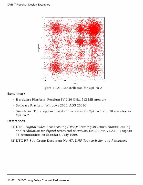
DVB-T Receiver Design Examples
Figure 11-21. Constellation for Option 2
Benchmark
• Hardware Platform: Pentium IV 2.26 GHz, 512 MB memory
• Software Platform: Windows 2000, ADS 2003C
• Simulation Time: approximately 15 minutes for Option 1 and 30 minutes forOption 2
References
[1]ETSI, Digital Video Broadcasting (DVB); Framing structure, channel codingand modulation for digital terrestrial television. EN300 744 v1.2.1, EuropeanTelecommunication Standard, July 1999.
[2] DTG RF Sub-Group Document No. 67, UHF Transmission and Reception.
11-22 DVB-T Long Delay Channel Performance

DVB-T Analog Adjacent Channel PerformanceDTV_DVBT_Rx_PAL_Adj_Option1.dsnDTV_DVBT_Rx_PAL_Adj_Option2.dsn
Features: Option 1 Design
• 2K mode
• 64-QAM mapping
• 2/3 coding rate
• 1/32 guard interval
• Signal_Generation_VARs and Measurement_VARs parameters can be set bythe user
Features: Option 2 Design
• 2K mode
• 16-QAM mapping
• 3/4 coding rate
• 1/32 guard interval
• Signal_Generation_VARs and Measurement_VARs parameters can be set bythe user
DVB-T Analog Adjacent Channel Performance 11-23

DVB-T Receiver Design Examples
Description
These designs measure the protection ratio of an adjacent channel PAL signal. BERis measured after Viterbi decoding.
The schematic is shown in Figure 11-22.
Figure 11-22. DTV_DVBT_Rx_PAL_Adj Schematic
11-24 DVB-T Analog Adjacent Channel Performance

Simulation Results
For Option 1, the adjacent channel PAL signal interference level relative to thewanted DVB-T signal is 35 dB.
For Option 2, the adjacent channel PAL signal interference level relative to thewanted DVB-T signal is 37 dB.
Simulation results displayed in DTV_DVBT_Rx_PAL_Adj_Option1.dds andDTV_DVBT_Rx_PAL_Adj_Option2.dds are shown in Figure 11-23.
Figure 11-23. BER for Option 1 and Option 2
DVB-T Analog Adjacent Channel Performance 11-25

DVB-T Receiver Design Examples
For Option 1, the spectrum is shown in Figure 11-24; the demodulated constellationis shown in Figure 11-25.
Figure 11-24. Spectrum for Option 1
Figure 11-25. Constellation for Option 1
11-26 DVB-T Analog Adjacent Channel Performance

For Option 2, the spectrum is shown in Figure 11-26; the demodulated constellationis shown in Figure 11-27.
Figure 11-26. Spectrum for Option 2
Figure 11-27. Constellation for Option 2
DVB-T Analog Adjacent Channel Performance 11-27

DVB-T Receiver Design Examples
Benchmark
• Hardware Platform: Pentium IV 2.26 GHz, 512 MB memory
• Software Platform: Windows 2000, ADS 2003C
• Simulation Time: approximately 10 minutes
References
[1]ETSI, Digital Video Broadcasting (DVB); Framing structure, channel codingand modulation for digital terrestrial television. EN300 744 v1.2.1, EuropeanTelecommunication Standard, July 1999.
[2] DTG RF Sub-Group Document No. 67, UHF Transmission and Reception.
11-28 DVB-T Analog Adjacent Channel Performance
DVB-T Analog Co-Channel PerformanceDTV_DVBT_Rx_PAL_Cochannel_Option1.dsnDTV_DVBT_Rx_PAL_Cochannel_Option2.dsn
Features: Option 1 Design
• 2K mode
• 64-QAM mapping
• 2/3 coding rate
• 1/32 guard interval
• Signal_Generation_VARs and Measurement_VARs parameters can be set bythe user
Features: Option 2 Design
• 2K mode
• 16-QAM mapping
• 3/4 coding rate
• 1/32 guard interval
• Signal_Generation_VARs and Measurement_VARs parameters can be set bythe user
Description
These designs measure the protection ratio of a co-channel PAL signal. BER ismeasured after Viterbi decoding.
The schematic is shown in Figure 11-28.
DVB-T Analog Co-Channel Performance 11-29

DVB-T Receiver Design Examples
Figure 11-28. DTV_DVBT_Rx_PAL_Cochannel Schematic
Simulation Results
For Option 1, the co-channel PAL signal interference level relative to the wantedDVB-T signal is 0 dB. Simulation results displayed inDTV_DVBT_Rx_PAL_Cochannel_Option1.dds are shown in Figure 11-29.
For Option 2, the co-channel PAL signal interference level relative to the wantedDVB-T signal is 0 dB. Simulation results displayed inDTV_DVBT_Rx_PAL_Cochannel_Option2.dds are shown in Figure 11-30.
Figure 11-29. BER for Option 1
Figure 11-30. BER for Option 2
11-30 DVB-T Analog Co-Channel Performance
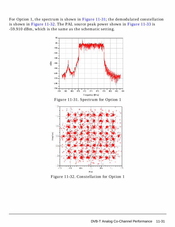
For Option 1, the spectrum is shown in Figure 11-31; the demodulated constellationis shown in Figure 11-32. The PAL source peak power shown in Figure 11-33 is-59.910 dBm, which is the same as the schematic setting.
Figure 11-31. Spectrum for Option 1
Figure 11-32. Constellation for Option 1
DVB-T Analog Co-Channel Performance 11-31

DVB-T Receiver Design Examples
Figure 11-33. PAL Source Peak Power for Option 1
11-32 DVB-T Analog Co-Channel Performance

For Option 2, the demodulated constellation is shown in Figure 11-34; thedemodulated constellation is shown in Figure 11-35. The PAL source peak powershown in Figure 11-36 is -59.910 dBm, which is the same as the schematic setting.
Figure 11-34. Spectrum for Option 2
Figure 11-35. Constellation for Option 2
DVB-T Analog Co-Channel Performance 11-33

DVB-T Receiver Design Examples
Figure 11-36. PAL Source Peak Power for Option 2
11-34 DVB-T Analog Co-Channel Performance

Benchmark
• Hardware Platform: Pentium IV 2.26 GHz, 512 MB memory
• Software Platform: Windows 2000, ADS 2003C
• Simulation Time: approximately 5 minutes
References
[1]ETSI, Digital Video Broadcasting (DVB); Framing structure, channel codingand modulation for digital terrestrial television. EN300 744 v1.2.1, EuropeanTelecommunication Standard, July 1999.
[2] DTG RF Sub-Group Document No. 67, UHF Transmission and Reception.
DVB-T Analog Co-Channel Performance 11-35

DVB-T Receiver Design Examples
DVB-T Image Channel PerformanceDTV_DVBT_Rx_PAL_Image_Option1.dsnDTV_DVBT_Rx_PAL_Image_Option2.dsn
Features: Option 1 Design
• 2K mode
• 64-QAM mapping
• 2/3 coding rate
• 1/32 guard interval
• Signal_Generation_VARs and Measurement_VARs parameters can be set bythe user
Features: Option 2 Design
• 2K mode
• 16-QAM mapping
• Coding rate is 3/4
• Guard interval is 1/32
• Signal_Generation_VARs and Measurement_VARs parameters can be set bythe user
Description
These designs measure the protection ratio of an image channel PAL signal.
The schematic is shown in Figure 11-37.
11-36 DVB-T Image Channel Performance

Figure 11-37. DTV_DVBT_Rx_PAL_Image Schematic
Simulation Results
BER is measured after Viterbi decoding.
For Option 1, the image channel PAL signal interference level relative to wantedDVB-T signal is 46 dB.
For Option 2, the image channel PAL signal interference level relative to wantedDVB-T signal is 50 dB.
Simulation results displayed in DTV_DVBT_Rx_PAL_Image_Option1.dds andDTV_DVBT_Rx_PAL_Image_Option2.dds are shown in Figure 11-38.
Figure 11-38. BER for Option 1 and Option 2
DVB-T Image Channel Performance 11-37
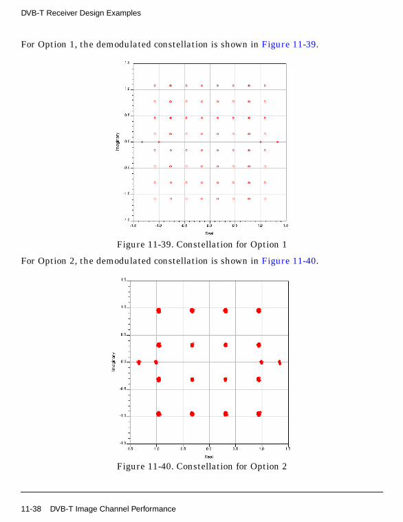
DVB-T Receiver Design Examples
For Option 1, the demodulated constellation is shown in Figure 11-39.
Figure 11-39. Constellation for Option 1
For Option 2, the demodulated constellation is shown in Figure 11-40.
Figure 11-40. Constellation for Option 2
11-38 DVB-T Image Channel Performance
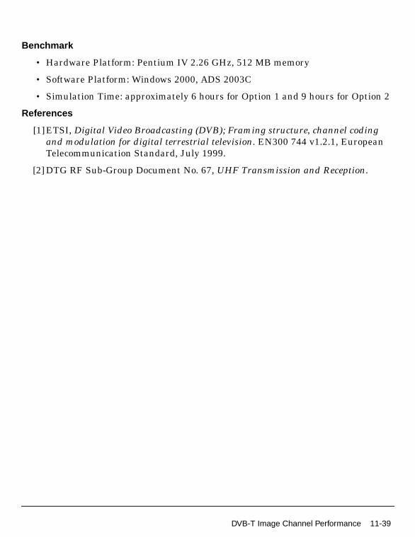
Benchmark
• Hardware Platform: Pentium IV 2.26 GHz, 512 MB memory
• Software Platform: Windows 2000, ADS 2003C
• Simulation Time: approximately 6 hours for Option 1 and 9 hours for Option 2
References
[1]ETSI, Digital Video Broadcasting (DVB); Framing structure, channel codingand modulation for digital terrestrial television. EN300 744 v1.2.1, EuropeanTelecommunication Standard, July 1999.
[2] DTG RF Sub-Group Document No. 67, UHF Transmission and Reception.
DVB-T Image Channel Performance 11-39

DVB-T Receiver Design Examples
DVB-T Rayleigh Channel (P1) PerformanceDTV_DVBT_Rx_Rayleigh_Option1.dsnDTV_DVBT_Rx_Rayleigh_Option2.dsn
Features: Option 1 Design
• 2K mode
• 64-QAM mapping
• 2/3 coding rate
• 1/32 guard interval
• Signal_Generation_VARs and RF_Channel_Measurement_VARs parameterscan be changed by the user
Features: Option 2 Design
• 2K mode
• 16-QAM mapping
• 3/4 coding rate
• 1/32 guard interval
• Signal_Generation_VARs and RF_Channel_Measurement_VARs parameterscan be changed by the user
Description
These designs measure the performance of a DVB-T receiver with a Rayleigh channel(P1).
BER is measured after Viterbi decoding.
The schematic is shown in Figure 11-41.
11-40 DVB-T Rayleigh Channel (P1) Performance

Figure 11-41. DTV_DVBT_Rx_Rayleigh Schematic
Simulation Results
For Option 1, a 22.6 dB carrier-to-noise ratio is used. Simulation results displayed inDTV_DVBT_Rx_Rayleigh_Option1.dds are shown in Figure 11-42. The demodulatedconstellation is shown in Figure 11-43.
Figure 11-42. BER for Option 1
DVB-T Rayleigh Channel (P1) Performance 11-41

DVB-T Receiver Design Examples
Figure 11-43. Constellation for Option 1
11-42 DVB-T Rayleigh Channel (P1) Performance

For Option 2, a 19.1 dB carrier-to-noise ratio is used. Simulation results displayed inDTV_DVBT_Rx_Rayleigh_Option2.dds are shown in Figure 11-44. The demodulatedconstellation is shown in Figure 11-45.
Figure 11-44. BER for Option 2
Figure 11-45. Constellation for Option 2
Benchmark
• Hardware Platform: Pentium IV 2.26 GHz, 512 MB memory
• Software Platform: Windows 2000, ADS 2003C
• Simulation Time: approximately 1 minute
DVB-T Rayleigh Channel (P1) Performance 11-43

DVB-T Receiver Design Examples
References
[1]ETSI, Digital Video Broadcasting (DVB); Framing structure, channel codingand modulation for digital terrestrial television. EN300 744 v1.2.1, EuropeanTelecommunication Standard, July 1999.
[2] DTG RF Sub-Group Document No. 67, UHF Transmission and Reception.
11-44 DVB-T Rayleigh Channel (P1) Performance

DVB-T Ricean Channel (F1) PerformanceDTV_DVBT_Rx_Ricean_Option1.dsnDTV_DVBT_Rx_Ricean_Option2.dsn
Features: Option 1 Design
• 2K mode
• 64-QAM mapping
• 2/3 coding rate
• 1/32 guard interval
• Signal_Generation_VARs and RF_Channel_Measurement_VARs parameterscan be changed by the user
Features: Option 2 Design
• 2K mode
• 16-QAM mapping
• 3/4 coding rate
• 1/32 guard interval
• Signal_Generation_VARs and RF_Channel_Measurement_VARs parameterscan be changed by the user
Description
These designs measure the performance of a DVB-T receiver with a Ricean channel(F1). BER is measured after Viterbi decoding.
The schematic is shown in Figure 11-46.
DVB-T Ricean Channel (F1) Performance 11-45

DVB-T Receiver Design Examples
Figure 11-46. DTV_DVBT_Rx_Ricean Schematic
11-46 DVB-T Ricean Channel (F1) Performance

Simulation Results
For option 1, a 19.4 dB carrier-to-noise ratio is used. Simulation results displayed inDTV_DVBT_Rx_Ricean_Option1.dds are shown in Figure 11-47. The demodulatedconstellation is shown in Figure 11-48.
Figure 11-47. BER for Option 1
Figure 11-48. Constellation for Option 1
DVB-T Ricean Channel (F1) Performance 11-47

DVB-T Receiver Design Examples
For option 2, a 14.9 dB carrier-to-noise ratio is used. Simulation results displayed inDTV_DVBT_Rx_Ricean_Option2.dds are shown in Figure 11-49. The demodulatedconstellation is shown in Figure 11-50.
Figure 11-49. BER for Option 2
Figure 11-50. Constellation for Option 2
Benchmark
• Hardware Platform: Pentium IV 2.26 GHz, 512 MB memory
• Software Platform: Windows 2000, ADS 2003C
• Simulation Time: approximately 1 minute
References
[1]ETSI, Digital Video Broadcasting (DVB); Framing structure, channel codingand modulation for digital terrestrial television. EN300 744 v1.2.1, EuropeanTelecommunication Standard, July 1999.
[2] DTG RF Sub-Group Document No. 67, UHF Transmission and Reception.
11-48 DVB-T Ricean Channel (F1) Performance
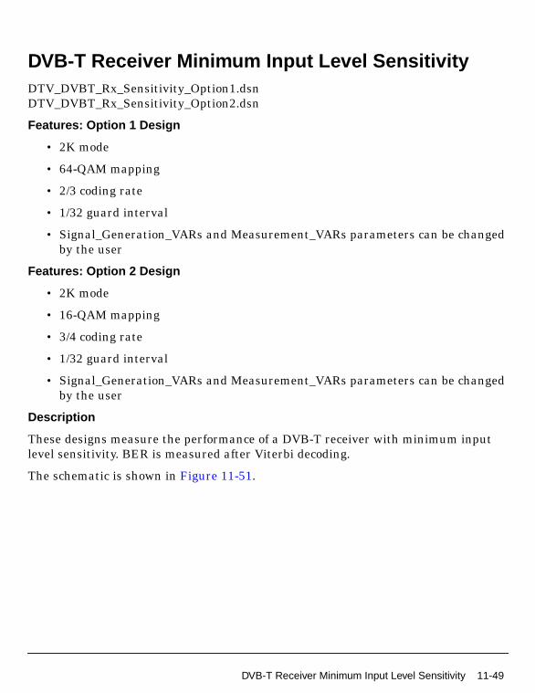
DVB-T Receiver Minimum Input Level SensitivityDTV_DVBT_Rx_Sensitivity_Option1.dsnDTV_DVBT_Rx_Sensitivity_Option2.dsn
Features: Option 1 Design
• 2K mode
• 64-QAM mapping
• 2/3 coding rate
• 1/32 guard interval
• Signal_Generation_VARs and Measurement_VARs parameters can be changedby the user
Features: Option 2 Design
• 2K mode
• 16-QAM mapping
• 3/4 coding rate
• 1/32 guard interval
• Signal_Generation_VARs and Measurement_VARs parameters can be changedby the user
Description
These designs measure the performance of a DVB-T receiver with minimum inputlevel sensitivity. BER is measured after Viterbi decoding.
The schematic is shown in Figure 11-51.
DVB-T Receiver Minimum Input Level Sensitivity 11-49

DVB-T Receiver Design Examples
Figure 11-51. DTV_DVBT_Rx_Sensitivity Schematic
11-50 DVB-T Receiver Minimum Input Level Sensitivity

Simulation Results
BER is measured after Viterbi decoding.
Option 1 uses a signal power level of -77.9 dBm. Simulation results displayed inDTV_DVBT_Rx_Sensitivity_Option1.dds are shown in Figure 11-52. Thedemodulated constellation is shown in Figure 11-53.
Figure 11-52. BER for Option 1
Figure 11-53. Constellation for Option 1
DVB-T Receiver Minimum Input Level Sensitivity 11-51

DVB-T Receiver Design Examples
Option 2 uses a signal power level of -82.1 dBm. Simulation results displayed inDTV_DVBT_Rx_Sensitivity_Option2.dds are shown in Figure 11-54. Thedemodulated constellation is shown in Figure 11-55.
Figure 11-54. BER for Option 2
Figure 11-55. Constellation for Option 2
11-52 DVB-T Receiver Minimum Input Level Sensitivity

Benchmark
• Hardware Platform: Pentium IV 2.26 GHz, 512 MB memory
• Software Platform: Windows 2000, ADS 2003C
• Simulation Time: approximately 1 minute
References
[1]ETSI, Digital Video Broadcasting (DVB); Framing structure, channel codingand modulation for digital terrestrial television. EN300 744 v1.2.1, EuropeanTelecommunication Standard, July 1999.
[2] DTG RF Sub-Group Document No. 67, UHF Transmission and Reception.
DVB-T Receiver Minimum Input Level Sensitivity 11-53

DVB-T Receiver Design Examples
DVB-T Short Delay Channel PerformanceDTV_DVBT_Rx_ShortDelay_Option1.dsnDTV_DVBT_Rx_ShortDelay_Option2.dsn
Features: Option 1 Design
• 2K mode
• 64-QAM mapping
• 2/3 coding rate
• 1/32 guard interval
• Signal_Generation_VARs and RF_Channel_Measurement_VARs parameterscan be changed by the user
Features: Option 2 Design
• 2K mode
• 16-QAM mapping
• 3/4 coding rate
• 1/32 guard interval
• Signal_Generation_VARs and RF_Channel_Measurement_VARs parameterscan be changed by the user
Description
These designs measure the performance of a DVB-T receiver with a short delaychannel. The short delay combines 6 echoes. All echoes are within the guard intervaland none is dominant: there is no direct path. Path delay and attenuation of the shortdelay multipath channel are [0, 0.05, 0.4, 1.45, 2.3, 2.8] µsec and [2.8, 0.0, 3.8, 0.1,2.6, 1.3] dB. The phase is set to 0 at the channel center.
BER is measured after Viterbi decoding.
The schematic is shown in Figure 11-56.
11-54 DVB-T Short Delay Channel Performance

Figure 11-56. DTV_DVBT_Rx_ShortDelay Schematic
DVB-T Short Delay Channel Performance 11-55

DVB-T Receiver Design Examples
Simulation Results
Option 1 has a carrier-to-noise ratio of 22.3 dB. Simulation results displayed inDTV_DVBT_Rx_ShortDelay_Option1.dds are shown in Figure 11-57. Thedemodulated constellation is shown in Figure 11-58.
Figure 11-57. BER for Option 1
Figure 11-58. Constellation for Option 1
11-56 DVB-T Short Delay Channel Performance

Option 2 has a carrier-to-noise ratio of 18.8 dB. Simulation results displayed inDTV_DVBT_Rx_ShortDelay_Option2.dds are shown in Figure 11-59. Thedemodulated constellation is shown in Figure 11-60.
Figure 11-59. BER for Option 2
Figure 11-60. Constellation for Option 2
Benchmark
• Hardware Platform: Pentium IV 2.26 GHz, 512 MB memory
• Software Platform: Windows 2000, ADS 2003C
• Simulation Time: approximately 15 minutes for Option 1 and 25 minutes forOption 2
References
[1]ETSI, Digital Video Broadcasting (DVB); Framing structure, channel codingand modulation for digital terrestrial television. EN300 744 v1.2.1, EuropeanTelecommunication Standard, July 1999.
[2] DTG RF Sub-Group Document No. 67, UHF Transmission and Reception.
DVB-T Short Delay Channel Performance 11-57

DVB-T Receiver Design Examples
DVB-T Single Echo Channel PerformanceDTV_DVBT_Rx_SingleEcho_Option1.dsnDTV_DVBT_Rx_SingleEcho_Option2.dsn
Features: Option 1 Design
• 2K mode
• 64-QAM mapping
• 2/3 coding rate
• 1/32 guard interval
• Signal_Generation_VARs and RF_Channel_Measurement_VARs parameterscan be changed by the user
Features: Option 2 Design
• 2K mode
• 16-QAM mapping
• 3/4 coding rate
• 1/32 guard interval
• Signal_Generation_VARs and RF_Channel_Measurement_VARs parameterscan be changed by the user
Description
These designs measure the performance of a DVB-T receiver with a single echochannel. Path delay of the echo channel is 3.5 µsec and the attenuation is 0 dB. Theecho phase is set to 90 at the channel center.
BER is measured after Viterbi decoding.
The schematic is shown in Figure 11-61.
11-58 DVB-T Single Echo Channel Performance

Figure 11-61. DTV_DVBT_Rx_SingleEcho Schematic
DVB-T Single Echo Channel Performance 11-59

DVB-T Receiver Design Examples
Simulation Results
For option 1, a carrier-to-noise ratio of 23.1 dB is used. Simulation results displayedin DTV_DVBT_Rx_SingleEcho_Option1.dds are shown in Figure 11-62. Thedemodulated constellation is shown in Figure 11-63.
Figure 11-62. BER for Option 1
Figure 11-63. Constellation for Option 1
11-60 DVB-T Single Echo Channel Performance

For option 2, a carrier-to-noise ratio of 21.3 dB is used. Simulation results displayedin DTV_DVBT_Rx_SingleEcho_Option2.dds are shown in Figure 11-64. Thedemodulated constellation is shown in Figure 11-65.
Figure 11-64. BER for Option 2
Figure 11-65. Constellation for Option 2
Benchmark
• Hardware Platform: Pentium IV 2.26 GHz, 512 MB memory
• Software Platform: Windows 2000, ADS 2003C
• Simulation Time: approximately 2 minutes
References
[1]ETSI, Digital Video Broadcasting (DVB); Framing structure, channel codingand modulation for digital terrestrial television. EN300 744 v1.2.1, EuropeanTelecommunication Standard, July 1999.
[2] DTG RF Sub-Group Document No. 67, UHF Transmission and Reception.
DVB-T Single Echo Channel Performance 11-61

DVB-T Receiver Design Examples
11-62 DVB-T Single Echo Channel Performance

Chapter 12: ISDB-T System DesignExamples
IntroductionISDB-T design examples can be accessed from the ADS Main window File > ExampleProject > DTV. Schematics and simulation results for the following projects aredescribed in this chapter.
DTV_ISDB_prj
• DTV_ISDB_Demo_OneLay.dsn
• DTV_ISDB_Demo_TwoLay.dsn
• DTV_ISDB_Demo_ThreeLay.dsn
• DTV_ISDB_Demo_Partial.dsn
DTV_ISDBOFDM_prj
• DsnDTV_ISDBOFDM_64QAM.dsn
• DsnDTV_ISDBOFDM_DQPSK.dsn
• DsnDTV_ISDBOFDM_NTSCInterference.dsn
• DsnDTV_ISDBOFDM_TwoLay.dsn
• DsnDTV_ISDBOFDM_ThrLay.dsn
DTV_ISDBSystem_prj
• DsnDTV_ISDBOFDM_64QAM_BER.dsn
• DsnDTV_ISDBOFDM_DQPSK_BER.dsn
• DsnDTV_ISDBOneLay_64QAM.dsn
• DsnDTV_ISDBOneLay_DQPSK.dsn
• DsnDTV_ISDBTwoLay_System.dsn
• DsnDTV_ISDBThrLay_System.dsn
• DsnDTV_TMCCMod.dsn
• DsnDTV_TMCCThrLay.dsn
Introduction 12-1

ISDB-T System Design Examples
DTV ISDB Project ExamplesDTV_ISDB_prj
• DTV_ISDB_Demo_OneLay.dsn
• DTV_ISDB_Demo_TwoLay.dsn
• DTV_ISDB_Demo_ThreeLay.dsn
• DTV_ISDB_Demo_Partial.dsn
12-2 DTV ISDB Project Examples

DTV ISDB Demo for 1-Layer System
DTV_ISDB_Demo_OneLay.dsn
Features
• Mode: 8k (Mode 3)
• MappingMode: 64 QAM
• Inner code rate: 7/8
• Time interleave type: 2 (2 symbols)
• Segments: 13
• Guard interval: 1/8
• Oversampling ratio: 1
Description
This design is a 1-layer example of ISDB-T spectrum, constellation, MER, and BERmeasurements under an AWGN channel.
The schematic for this design is shown in Figure 12-1.
Users can change parameter settings in VAR and VAR1.
VAR2 contains delays needed for MER and BER measurements.
For BER measurements after Reed-Solomon decoding, users must take the followingaction:
• Move the starting point of the line that connects D1 and D3 from the currentpin to the uppermost pin in D1.
• Then, replace the delay parameter D_AfterDerandomize withD_AfterRSDecoder in D3 and D4.
DTV ISDB Project Examples 12-3

ISDB-T System Design Examples
Figure 12-1. DTV_ISDB_Demo_OneLay Schematic
12-4 DTV ISDB Project Examples

Simulation Results
The simulation is under an AWGN channel with a carrier-to-noise ratio of 22.0 dB.Simulation results are stored in DTV_ISDB_Demo_OneLay.dds and shown inFigure 12-2.
Figure 12-2. Simulation Results
Benchmark
• Hardware Platform: Pentium IV 2.26 GHz, 512 MB memory
• Software Platform: Windows 2000, ADS 2004A
• Simulation Time: approximately 10 minutes
References
[1]ARIB STD-B31 Version 1.5, Transmission System for Digital TerrestrialTelevision Broadcasting, July 29, 2003.
DTV ISDB Project Examples 12-5

ISDB-T System Design Examples
DTV ISDB Demo for 2-Layer System
DTV_ISDB_Demo_TwoLay.dsn
Features
• Mode: 8k (Mode 3)
• MappingMode: QPSK (layer A), 64 QAM (layer B)
• Inner code rate: 1/2 (layer A), 3/4 (layer B)
• Time interleave type: 2 (2 symbols, layer A), 2 (2 symbols, layer B)
• Segments: 1 (layer A), 12 (layer B)
• Guard interval: 1/8
• Oversampling ratio: 1
Description
This design is a 2-layer example of ISDB-T spectrum, constellation, MER, and BERmeasurements under an AWGN channel.
The schematic for this design is shown in Figure 12-3.
Parameters can be set through VAR, VAR1 and VAR2.
VAR3 and VAR4 contain delays needed for MER and BER measurements.
For BER measurements after Reed-Solomon decoding, users must take the followingaction:
• Move the starting point of the line that connects D1 and D3 from the currentpin Bytes_AftRSC to pin Bytes_Uncoded in D1.
• Then, replace the delay parameter D_AfterDerandomize withD_AfterRSDecoder in D3 and D4.
12-6 DTV ISDB Project Examples

Figure 12-3. DTV_ISDB_Demo_TwoLay Schematic
DTV ISDB Project Examples 12-7

ISDB-T System Design Examples
Simulation Results
The simulation is under an AWGN channel with carrier-to-noise ratio of 20.1 dB.Simulation results are stored in DTV_ISDB_Demo_TwoLay.dds and are shown inFigure 12-4.
Figure 12-4. Simulation Results
Benchmark
• Hardware Platform: Pentium IV 2.26 GHz, 512 MB memory
• Software Platform: Windows 2000, ADS 2004A
• Simulation Time: approximately 40 minutes
References
[1]ARIB STD-B31 Version 1.5, Transmission System for Digital TerrestrialTelevision Broadcasting, July 29, 2003.
12-8 DTV ISDB Project Examples

DTV ISDB Demo for 3-Layer System
DTV_ISDB_Demo_ThreeLay.dsn
Features
• Mode: 8k (Mode 3)
• MappingMode: QPSK (layer A), 16 QAM (layer B), 64 QAM (layer C)
• Inner code rate: 3/4 (layer A), 2/3 (layer B), 5/6 (layer C)
• Time interleave type: 2 (2 symbols, layer A), 2 (2 symbols, layer B), 2 (2 symbols,layer C)
• Segments: 1 (layer A), 4 (layer B), 8 (layer C)
• Guard interval: 1/8
• Oversampling ratio: 1
Description
This design is a 3-layer example of ISDB-T spectrum, constellation, MER, and BERmeasurements under an AWGN channel.
The schematic for this design is shown in Figure 12-5. Parameters can be set throughVAR, VAR1, VAR2, and VAR3.
VAR4, VAR5, and VAR6 contain delays needed for MER and BER measurements.
For BER measurements after Reed-Solomon decoding, users must take the followingaction:
• Move the starting point of the line that connects D1 and D3 from the currentpin Bytes_AftRSC to pin Bytes_Uncoded in D1.
• Then, replace the delay parameter D_AfterDerandomize withD_AfterRSDecoder in D3 and D4.
DTV ISDB Project Examples 12-9

ISDB-T System Design Examples
Figure 12-5. DTV_ISDB_Demo_ThreeLay Schematic
12-10 DTV ISDB Project Examples

Simulation Results
The simulation is under AWGN channel with the C/N (Carrier to Noise Ratio) of 13.5dB. Simulation results are stored in DTV_ISDB_Demo_ThreeLay.dds and are alsoshown in Figure 12-2.
Figure 12-6. Simulation Results
Benchmark
• Hardware Platform: Pentium IV 2.26 GHz, 512 MB memory
• Software Platform: Windows 2000, ADS 2004A
• Simulation Time: approximately 6 minutes
References
[1]ARIB STD-B31 Version 1.5, Transmission System for Digital TerrestrialTelevision Broadcasting, July 29, 2003.
DTV ISDB Project Examples 12-11

ISDB-T System Design Examples
DTV ISDB Demo for Partial Reception System
DTV_ISDB_Demo_Partial.dsn
Features
• Mode: 8k (Mode 3)
• MappingMode: 16 QAM (layer A), 64 QAM (layer B)
• Inner code rate: 1/2 (layer A), 7/8 (layer B)
• Time interleave type: 2 (2 symbols, layer A), 2 (2 symbols, layer B)
• Segments: 1 (layer A), 12 (layer B)
• Guard interval: 1/8
• Oversampling ratio: 1
Description
This design is a partial reception example of ISDB-T spectrum, constellation, MERand BER measurements under fading channel.
The schematic for this design is shown in Figure 12-7. Parameters that can bechanged by users are contained in VAR, Var1 and VAR2.
Var3 contains delays needed for MER and BER measurements.
For BER measurements after Reed-Solomon decoding, users must take the followingaction:
• Move the starting point of the line that connects D1 and D3 from the currentpin to the upper pin in D1.
• Then, replace the delay parameter D_AfterDerandomize withD_AfterRSDecoder in D3 and D4.
12-12 DTV ISDB Project Examples

Figure 12-7. DTV_ISDB_Demo_Partial Schematic
Simulation Results
The simulation is under a fading channel without AWGN. Simulation results arestored in DTV_ISDB_Demo_Partial.dds and are shown in Figure 12-8.
DTV ISDB Project Examples 12-13

ISDB-T System Design Examples
Figure 12-8. Simulation Results
Benchmark
• Hardware Platform: Pentium IV 2.26 GHz, 512 MB memory
• Software Platform: Windows 2000, ADS 2004A
• Simulation Time: approximately 8 minutes
References
[1]ARIB STD-B31 Version 1.5, Transmission System for Digital TerrestrialTelevision Broadcasting, July 29, 2003.
12-14 DTV ISDB Project Examples

DTV ISDB OFDM Project ExampleDTV_ISDBOFDM_prj
• DsnDTV_ISDBOFDM_64QAM.dsn
• DsnDTV_ISDBOFDM_DQPSK.dsn
• DsnDTV_ISDBOFDM_NTSCInterference.dsn
• DsnDTV_ISDBOFDM_TwoLay.dsn
• DsnDTV_ISDBOFDM_ThrLay.dsn
DTV ISDB OFDM Project Example 12-15

ISDB-T System Design Examples
OFDM 64-QAM Modulation and Demodulation in ISDB-TSystems
DTV_ISDBOFDM_prj Design Name
DsnDTV_ISDBOFDM_64QAM.dsn
Features
• 64-QAM modulation and demodulation
• Guard interval
• TDMA multipath fading channel with Doppler shift. The type of multipath canbe selected; Doppler shift can be determined by the mobile speed setting.
• Displays include:ML (maximum likelihood)RxSpectrum (spectrum of received signal from the channel)RxQAM (received signal constellation after OFDM demodulation)
Description
This design is an example of modulation, transmission and demodulation sections viaa TDMA multipath channel with Doppler shift. In this example, a single layertransmission is used in mode 3, which includes 13 segments. Modulation mapping is64-QAM; the guard interval ratio is 1/16.
After 64-QAM data mapping, the 13 OFDM segments are formed by adding TMCCand AC data, and scattered pilots. After the spectral order of the segments ischanged, 8192-point inverse FFT (IFFT) is performed. After inserting the guardinterval, the complex signal is transmitted; the transmitted signal length is8192+guard interval.
In the receiver, the FFT starting point is determined by the ML function of thereceived signal. After FFT, the transmitted signal is recovered by a simple frequencyequalizer. According to the ISDB-T, the mapping data was received. Data is recoveredby the 64-QAM demodulator.
System performance can be viewed during simulation.
12-16 DTV ISDB OFDM Project Example

Schematics
Figure 12-9 shows the schematic for this design; subnetwork designs are shown inFigure 12-10 and Figure 12-11.
Figure 12-9. DsnDTV_ISDBOFDM_64QAM.dsn
Figure 12-10. sub_ISDBOFDM_Mod.dsn
Figure 12-11. sub_ISDBOFDM_Demod.dsn
DTV ISDB OFDM Project Example 12-17

ISDB-T System Design Examples
Specifications
Notes
1. In this example, the guard interval ratio is 1/16, so the guard interval is 512.(According to ISDB-T, in mode 3 the guard interval is 256, 512, 1024, or 2048,which corresponds to 1/32, 1/16, 1/8, or 1/4 guard interval ratio, respectively.)
2. All parameters are related to the guard interval (except TDMA channelparameters). If the guard interval is changed, parameters will be changed tothe corresponding values.
3. The TDMA channel condition varies according to channel parametermodification. Parameters include Type, Pathloss, Env, Delay, and Test in thePropNADCtdma model, and Vx and Vy in the AntMobile model.
Simulation Results
Figure 12-12. ML magnitude,shows the magnitude of ML function of received signal used to find FFT start.
The maximum value appears in every (8192+512) points,the point of the maximum magnitude value is the FFT start.
Symbol (Model)Specification(Parameter) Simulation Type Value
PropNADCtdma Type ADS Ptolemy TwoPath
PropNADCtdma Pathloss ADS Ptolemy No
PropNADCtdma Env ADS Ptolemy TypicalUrban
PropNADCtdma Delay ADS Ptolemy 1.0 µsec
PropNADCtdma Test ADS Ptolemy Tap1
AntMobile Vx ADS Ptolemy 30 km/hr
AntMobile Vy ADS Ptolemy 0.0 km/hr
12-18 DTV ISDB OFDM Project Example

Figure 12-13. Received constellation after OFDM demodulation by TDMA channel.Results show OFDM system performance.
Figure 12-14. Spectrum of signal received from wireless channel.Center frequency is 611MHz
Figure 12-15. Adjacent-Channel Power RatioThe equation is:
ACPR=acpr_vr(DsnDTV_ISDBOFDM_64QAM.RxSignal,50.0,-2.808MHz,2.808MHz,-8.808MHz,-3.192MHz,3.192MHz,8.808MHz)
DTV ISDB OFDM Project Example 12-19

ISDB-T System Design Examples
Figure 12-16. Relative magnitude error, which is defined as:EVM=mag(DsnDTV_ISDBOFDM_64QAM..
RxQAM-DsnDTV_ISDBOFDM_64QAM..TxQAM)/mean(mag(DsnDTV_ISDBOFDM_64QAM..TxQAM))
Figure 12-17. EVM histogram, which shows most EVM < 0.1.EVMhist is defined as:
EVMhist=histogram(EVM,1001,0.0,1.0)
Figure 12-18. EVMavr=mean(EVM)
12-20 DTV ISDB OFDM Project Example

Benchmark
• Hardware Platform: Pentium II 200 MHz, 96 MB memory
• Software Platform: WindowsNT 4.0 Workstation, ADS 1.3
• Data Points: 10 symbols
• Simulation Time: 78 seconds
References
[1]ARIB-JAPAN, “Terrestrial Integrated Services Digital Broadcasting (ISDB-T);Specification of Channel Coding, Framing Structure and Modulation,”Sept.1998.
DTV ISDB OFDM Project Example 12-21

ISDB-T System Design Examples
OFDM DQPSK Modulation and Demodulation in ISDB-T Systems
DTV_ISDBOFDM_prj Design Name
DsnDTV_ISDBOFDM_DQPSK.dsn
Features
• DQPSK modulation and demodulation
• Guard interval
• TDMA multipath fading channel with Doppler shift. The multipath type can beselected and the Doppler shift can be determined by setting the mobile’s speed.
• Displays include:ML (maximum likelihood function)RxSpectrum (spectrum of signal received from the channel)RxDQPSK (received signal constellation after OFDM demodulation)
Description
This design is an example of modulation, transmission and demodulation sections viaa TDMA multipath channel with Doppler shift. In this example, a single layertransmission is used in mode 3, which includes 13 segments. Modulation mapping isDQPSK; the guard interval ratio is 1/16.
After DQPSK data mapping, the 13 OFDM segments are formed by adding TMCCand AC data, and scattered pilots. After the spectral order of the segments ischanged, 8192-point inverse FFT (IFFT) is performed. After inserting the guardinterval, the complex signal is transmitted; the transmitted signal length is8192+guard interval.
In the receiver, the FFT starting point is determined by the ML function of thereceived signal. After FFT, the transmitted signal is recovered by simple frequencyequalizer. According to the ISDB-T, the mapping data was received. TSP data isrecovered by the DQPSK demodulator.
System performance can be viewed during simulation.
Schematics
Figure 12-19 shows the schematic for this design; subnetwork designs are shown inFigure 12-20 and Figure 12-21.
12-22 DTV ISDB OFDM Project Example

Figure 12-19. DsnDTV_ISDBOFDM_DQPSK.dsn
Figure 12-20. sub_ISDBOFDM_Mod.dsn
Figure 12-21. sub_ISDBOFDM_Demod.dsn
DTV ISDB OFDM Project Example 12-23

ISDB-T System Design Examples
Specifications
Notes
1. In this example, the guard interval ratio is 1/16, so the guard interval is 512.(According to ISDB-T, in mode 3 the guard interval is 256, 512, 1024, or 2048,which corresponds to 1/32, 1/16, 1/8, or 1/4 guard interval ratio, respectively.)
2. All parameters are related to the guard interval (except TDMA channelparameters). If the guard interval is changed, parameters will be changed tothe corresponding values.
3. The TDMA channel condition varies according to channel parametermodification. Parameters include Type, Pathloss, Env, Delay, and Test in thePropNADCtdma model, and Vx and Vy in the AntMobile model.
Simulation Results
Figure 12-22. ML magnitude which shows the magnitude of ML function of thereceived signal used to find the FFT start. The maximum value appears in every(8192+512) points, the point of the maximum magnitude value is the FFT start.
Symbol (Model)Specification(Parameter) Simulation Type Value
PropNADCtdma Type ADS Ptolemy TwoPath
PropNADCtdma Pathloss ADS Ptolemy No
PropNADCtdma Env ADS Ptolemy TypicalUrban
PropNADCtdma Delay ADS Ptolemy 6 µsec
PropNADCtdma Test ADS Ptolemy Tap1
AntMobile Vx ADS Ptolemy 30 km/hr
AntMobile Vy ADS Ptolemy 0.0 km/hr
12-24 DTV ISDB OFDM Project Example

Figure 12-23. Received constellation after OFDM demodulation by TDMA channel.Results show OFDM system performance.
Figure 12-24. Spectrum of Signal Received from Wireless Channel.Center frequency is 611 MHz
Figure 12-25. Adjacent-Channel Power RatioThe equation is:
ACPR=acpr_vr(DsnDTV_ISDBOFDM_DQPSK..RxSignal,50.0,-2.808MHz,2.808MHz,-8.808MHz,-3.192MHz,3.192MHz,8.808MHz)
DTV ISDB OFDM Project Example 12-25

ISDB-T System Design Examples
Figure 12-26. Relative magnitude error, which is defined as:EVM=mag(DsnDTV_ISDBOFDM_DQPSK..RxDQPSK-DsnDTV_ISDBOFDM_DQPSK..
TxDQPSK)/mean(mag(DsnDTV_ISDBOFDM_DQPSK..TxDQPSK))
Figure 12-27. Histogram of EVM, which shows most EVM < 0.1.EVMhist is defined as:
EVMhist=histogram(EVM,1001,0.0,1.0)
Benchmark
• Hardware Platform: Pentium II 200 MHz, 96 MB memory
• Software Platform: WindowsNT 4.0 Workstation, ADS 1.3
• Data Points: 10 symbols
• Simulation Time: 110 seconds
12-26 DTV ISDB OFDM Project Example
References
[1]ARIB-JAPAN, “Terrestrial Integrated Services Digital Broadcasting (ISDB-T);Specification of Channel Coding, Framing Structure and Modulation,”Sept.1998.
DTV ISDB OFDM Project Example 12-27

ISDB-T System Design Examples
DTV and NTSC Signal Interference Test in ISDB-T Systems
DTV_ISDBOFDM_prj Design Name
DsnDTV_ISDBOFDM_NTSCInterference.dsn
Features
• 64-QAM modulation and demodulation
• Adjacent channel interference between NTSC and ISDB-T signal
• Displays include:ML (maximum likelihood function),RxSpectrum (spectrum of signal received from the channel),RxQAM (received signal constellation after OFDM demodulation),Videoin, Videoout
• Comparison of analog NTSC TV signal and received NTSC TV signal that hasadjacent channel ISDB-T signal interference
Description
This design is an OFDM example that tests the adjacent interference between theanalog NTSC TV signal and the digital ISDB-T signal. ISDB-T signal experiencesweak interference while the analog NTSC signal experiences strong interference.This effect is saved in Data Display (DsnDTV_ISDBOFDM_NTSCInterference1.dds).The analog NTSC spectrum experiences interference at frequencies over 6 MHz. TheISDB-T signal center frequency is 611.15 MHz, which is shifted 150 kHz.
Schematics
Figure 12-28 shows the schematic for this design; subnetwork designs are shown inFigure 12-29 through Figure 12-32.
Figure 12-28. DsnDTV_ISDBOFDM_NTSCInterference.dsn
12-28 DTV ISDB OFDM Project Example
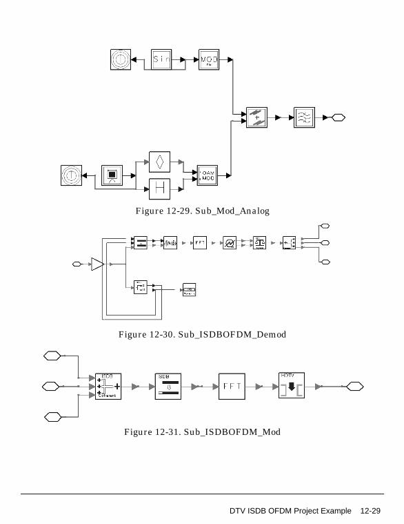
Figure 12-29. Sub_Mod_Analog
Figure 12-30. Sub_ISDBOFDM_Demod
Figure 12-31. Sub_ISDBOFDM_Mod
DTV ISDB OFDM Project Example 12-29

ISDB-T System Design Examples
Figure 12-32. Sub_Demod_Analog
Specifications
Notes
1. In this example, the guard interval ratio is 1/16, so the guard interval is 512.(According to ISDB-T, in mode 3 the guard interval is 256, 512, 1024, or 2048,which corresponds to 1/32, 1/16, 1/8, or 1/4 guard interval ratio, respectively.)
2. All parameters are related to the guard interval (except TDMA channelparameters). If the guard interval is changed, parameters will be changed tothe corresponding values.
3. The TDMA channel condition varies according to channel parametermodification. Parameters include Type, Pathloss, Env, Delay, and Test in thePropNADCtdma model, and Vx and Vy in the AntMobile model.
Specification (Parameter) Simulation Type Value
Carriers ADS Ptolemy 432
Segments ADS Ptolemy 13
IFFTSize ADS Ptolemy 8192*4
FFTSize ADS Ptolemy 8192*4
GuardInterval ADS Ptolemy 512*4
IFFTOrder ADS Ptolemy 15
FFTOrder ADS Ptolemy 15
MaxDelay ADS Ptolemy 8192*4
12-30 DTV ISDB OFDM Project Example

Simulation Results
Figure 12-33. ML magnitude which shows the magnitude of ML function of receivedsignal used to find FFT start. Maximum value appears in every 4*(8192+512) points,
the point of the maximum magnitude value is the FFT start.
Figure 12-34. Received 64QAM Constellation afterOFDM demodulation by TDMA channel with
NTSC Signal Interference.
DTV ISDB OFDM Project Example 12-31

ISDB-T System Design Examples
Figure 12-35. Spectrum of Signal Received from Wireless Channel
Figure 12-36. NTSC Video Input and Output Signalswith ISDB-T Signal Interference
12-32 DTV ISDB OFDM Project Example
Benchmark
• Hardware Platform: Pentium II 200 MHz, 96 MB memory
• Software Platform: WindowsNT 4.0 Workstation, ADS 1.3
• Data Points: 10 symbols
• Simulation Time: 8.5 hours
References
[1]ARIB-JAPAN, “Terrestrial Integrated Services Digital Broadcasting (ISDB-T);Specification of Channel Coding, Framing Structure and Modulation,”Sept.1998.
DTV ISDB OFDM Project Example 12-33

ISDB-T System Design Examples
OFDM 2-Layer Modulation and Demodulation in ISDB-T Systems
DTV_ISDBOFDM_prj Design Name
DsnDTV_ISDBOFDM_TwoLay.dsn
Features
• 64-QAM modulation and demodulation
• DQPSK modulation and demodulation
• Guard interval
• TDMA multipath fading channel with Doppler shift. The kind of the multipathcan be selected and the Doppler shift can be determined by setting the mobile’sspeed.
• Displays include:ML (maximum likelihood function)RxSpectrum (spectrum of signal received from the channel)RxQAM (received signal constellation after OFDM demodulation)RxDQPSK
Description
This design is a 2-layer OFDM design example of ISDB-T. It includes 13 segments (5segments for Layer A, 8 segments for Layer B). Modulation modes are DQPSK and64-QAM in Layer A and Layer B, respectively.
The IFFT/ FFT size is 2048; the guard interval is 1/8 of IFFT size. The simulationchannel is the TDMA channel. The byte in transmitter and receiver, the receivedDQPSK constellation and 64-QAM constellation are shown in the simulation results.
Schematics
Figure 12-37 shows the schematic for this design; subnetwork designs are shown inFigure 12-38 and Figure 12-39.
12-34 DTV ISDB OFDM Project Example

Figure 12-37. DsnDTV_ISDBOFDM_TwoLay.dsn
Figure 12-38. sub_ISDBOFDM_TwoLayMod.dsn
Figure 12-39. sub_ISDBOFDM_TwoLayDemod.dsn
DTV ISDB OFDM Project Example 12-35

ISDB-T System Design Examples
Specifications
Notes
1. The modification of the guard interval is according to the ISDB-T. In mode 1,the value of the guard interval is 64, 128, 256, and 512 corresponding to the1/32, 1/16, 1/8, and 1/4 guard interval ratio, respectively. In this example, theguard interval ratio is 1/8, so the guard interval is 256.
2. All parameters are related to the guard interval (except TDMA channelparameters). If the guard interval is changed, parameters will be changed tothe corresponding values.
3. The TDMA channel condition varies according to channel parametermodification. Parameters include Type, Pathloss, Env, Delay, and Test in thePropNADCtdma model, and Vx and Vy in the AntMobile model.
Symbol (Model)Specification(Parameter) Simulation Type Value
Carriers ADS Ptolemy 108
Segments ADS Ptolemy 13
IFFTSize ADS Ptolemy 2048
FFTSize ADS Ptolemy 2048
Guard ADS Ptolemy 256
IFFTOrder ADS Ptolemy 11
FFTOrder ADS Ptolemy 11
MaxDelay ADS Ptolemy 2047
SegmentsA ADS Ptolemy 5
SegmentsB ADS Ptolemy 8
Ru ADS Ptolemy 0.9
PropNADCtdma Type ADS Ptolemy FlatFading
PropNADCtdma Pathloss ADS Ptolemy No
PropNADCtdma Env ADS Ptolemy TypicalUrban
PropNADCtdma Test ADS Ptolemy Tap1
AntMobile Vx ADS Ptolemy 30 km/hr
AntMobile Vy ADS Ptolemy 0.0 km/hr
12-36 DTV ISDB OFDM Project Example

Simulation Results
Figure 12-40. ML magnitude which shows the magnitude of ML function of thereceived signal used to find the FFT start. The maximum value appears in every(2048+128) points, the point of the maximum magnitude value is the FFT start.
Figure 12-41. Received 64-QAM constellationafter OFDM demodulation by TDMA channel.
Results show OFDM system performance.
Figure 12-42. Received DQPSK constellation afterOFDM demodulation by TDMA channel.
Results show OFDM system performance.
DTV ISDB OFDM Project Example 12-37

ISDB-T System Design Examples
Figure 12-43. Spectrum of Signal Received from Wireless Channel.Center frequency is 611 MHz
Figure 12-44. Adjacent-Channel Power RatioThe equation is:
ACPR=acpr_vr(DsnDTV_ISDBOFDM_TwoLay..RxSignal,50.0,-2.808MHz,2.808MHz, -8.808MHz,-3.192MHz, 3.192MHz,8.808MHz)
Benchmark
• Hardware Platform: Pentium II 200 MHz, 96 MB memory
• Software Platform: WindowsNT 4.0 Workstation, ADS 1.3
• Data Points: 10 symbols
• Simulation Time: 20 seconds
References
[1]ARIB-JAPAN, “Terrestrial Integrated Services Digital Broadcasting (ISDB-T);Specification of Channel Coding, Framing Structure and Modulation,”Sept.1998.
12-38 DTV ISDB OFDM Project Example

OFDM 3-Layer Modulation and Demodulation in ISDB-T Systems
DTV_ISDBOFDM_prj Design Name
DsnDTV_ISDBOFDM_ThrLay.dsn
Features
• 64-QAM modulation and demodulation
• DQPSK modulation and demodulation
• 16-QAM modulation and demodulation
• Guard interval
• TDMA multipath fading channel with Doppler shift. The kind of the multipathcan be selected and the Doppler shift can be determined by setting the mobile’sspeed.
• Displays include:ML (maximum likelihood function)RxSpectrum (spectrum of signal received from the channel)RxQAM (received signal constellation after OFDM demodulation)Rx16QAMRxDQPSK
Description
This design is a 3-layer OFDM design example of ISDB-T. It includes 13 segments (1segment for Layer A, 5 segments for Layer B, and 7 segments for Layer C). Themodulation modes are 64-QAM, and DQPSK, and 16-QAM, in Layer A, Layer B, andLayer C, respectively. In the OFDM adaptation, the 3-layer OFDM design works inmode 1. The IFFT/ FFT size is 2048; the Guard interval is 1/16 of IFFT size. Thesimulation channel is the TDMA channel.
The received 64-QAM, DQPSK, and 16-QAM constellations are shown in thesimulation results.
Schematics
Figure 12-45 shows the schematic for this design; subnetwork designs are shown inFigure 12-46 and Figure 12-47.
DTV ISDB OFDM Project Example 12-39
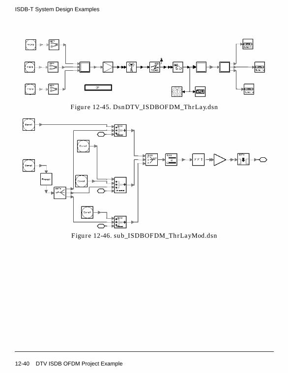
ISDB-T System Design Examples
Figure 12-45. DsnDTV_ISDBOFDM_ThrLay.dsn
Figure 12-46. sub_ISDBOFDM_ThrLayMod.dsn
12-40 DTV ISDB OFDM Project Example

Figure 12-47. sub_ISDBOFDM_ThrLayDemod.dsn
Specifications
Symbol (Model) Specification (Parameter) Simulation Type Value
Carriers ADS Ptolemy 108
Segments ADS Ptolemy 13
IFFTSize ADS Ptolemy 2048
FFTSize ADS Ptolemy 2048
Guard ADS Ptolemy 128
IFFTOrder ADS Ptolemy 11
FFTOrder ADS Ptolemy 11
MaxDelay ADS Ptolemy 2047
SegmentsA ADS Ptolemy 1
SegmentsB ADS Ptolemy 5
SegmentsC ADS Ptolemy 7
Ru ADS Ptolemy 0.9
PropNADCtdma Type ADS Ptolemy TwoPath
PropNADCtdma Pathloss ADS Ptolemy No
PropNADCtdma Env ADS Ptolemy TypicalUrban
PropNADCtdma Delay ADS Ptolemy 0.5 µsec
PropNADCtdma Test ADS Ptolemy Tap1
DTV ISDB OFDM Project Example 12-41

ISDB-T System Design Examples
Notes
1. The modification of the guard interval is according to the ISDB-T. In mode 1,the value of the guard interval is 64, 128, 256, and 512 corresponding to the1/32, 1/16, 1/8, and 1/4 guard interval ratio, respectively. In this example, theguard interval ratio is 1/16, so the guard interval is 128.
2. All parameters are related to the guard interval (except TDMA channelparameters). If the guard interval is changed, parameters will be changed tothe corresponding values.
3. The TDMA channel condition varies according to channel parametermodification. Parameters include Type, Pathloss, Env, Delay, and Test in thePropNADCtdma model, and Vx and Vy in the AntMobile model .
Simulation Results
Figure 12-48. ML magnitude which shows magnitude ofML function of received signal used to find FFT start.
Maximum value appears in every (2048+128) points, the point of the maximummagnitude value is the FFT start.
AntMobile Vx ADS Ptolemy 30 km/hr
AntMobile Vy ADS Ptolemy 0.0 km/hr
Symbol (Model) Specification (Parameter) Simulation Type Value
12-42 DTV ISDB OFDM Project Example
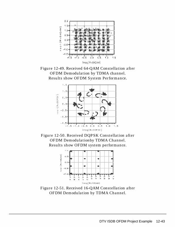
Figure 12-49. Received 64-QAM Constellation afterOFDM Demodulation by TDMA channel.
Results show OFDM System Performance.
Figure 12-50. Received DQPSK Constellation afterOFDM Demodulationby TDMA Channel.Results show OFDM system performance.
Figure 12-51. Received 16-QAM Constellation afterOFDM Demodulation by TDMA Channel.
DTV ISDB OFDM Project Example 12-43

ISDB-T System Design Examples
Figure 12-52. Spectrum of Signal Received from Wireless Channel.Center frequency = 611MHz
Figure 12-53. Adjacent-Channel Power Ratio.equation is:
ACPR=acpr_vr(DsnDTV_ISDBOFDM_ThrLay..RxSignal, 50.0,-2.808MHz,2.808MHz, -8.808MHz,-3.192MHz, 3.192MHz,8.808MHz)
Benchmark
• Hardware Platform: Pentium II 200 MHz, 96 MB memory
• Software Platform: WindowsNT 4.0 Workstation, ADS 1.3
• Data Points: 10 symbols
• Simulation Time: 500 seconds
References
[1]ARIB-JAPAN, “Terrestrial Integrated Services Digital Broadcasting (ISDB-T);Specification of Channel Coding, Framing Structure and Modulation,”Sept.1998.
12-44 DTV ISDB OFDM Project Example

DTV ISDB System Project ExamplesDTV_ISDBSystem_prj
• DsnDTV_ISDBOFDM_64QAM_BER.dsn
• DsnDTV_ISDBOFDM_DQPSK_BER.dsn
• DsnDTV_ISDBOneLay_64QAM.dsn
• DsnDTV_ISDBOneLay_DQPSK.dsn
• DsnDTV_ISDBTwoLay_System.dsn
• DsnDTV_ISDBThrLay_System.dsn
• DsnDTV_TMCCMod.dsn
• DsnDTV_TMCCThrLay.dsn
DTV ISDB System Project Examples 12-45

ISDB-T System Design Examples
OFDM 64-QAM ISDB-T System without Channel Coding BER
DTV_ISDBSystem_prj Design Name
DsnDTV_ISDBOFDM_64QAM_BER.dsn
Features
• 64-QAM modulation and demodulation
• Gaussian simulation channels
• Bit error rate is tested
• Without channel coding and interleaving
• Received signal constellation is displayed
Description
This design example is an OFDM adaptation for ISDB-T to test the BER of anISDB-T system without channel coding. In mode 1, the guard interval ratio is 1/8;modulation mode is 64-QAM.
Simulation results will be compared to those of DsnDTV_ISDBOneLay_64QAM.dsn,which tests the BER with channel coding and interleaving.
Schematics
Figure 12-54 shows the schematic for this design; subnetwork designs are shown inFigure 12-55 and Figure 12-56.
12-46 DTV ISDB System Project Examples

Figure 12-54. DsnDTV_ISDBOFDM_64QAM_BER.dsn
Figure 12-55. sub_ISDBOFDM_CohMod.dsn
Figure 12-56. sub_ISDBOFDM_CohDemod.dsn
DTV ISDB System Project Examples 12-47

ISDB-T System Design Examples
Specifications
Notes
1. The modification of the guard interval is according to the ISDB-T. In mode 1,the value of the guard interval is 64, 128, 256, and 512, corresponding to the1/32, 1/16, 1/8, and 1/4 guard interval ratio, respectively. In this example, theguard interval ratio is 1/8, so the guard interval is 256.
2. This design uses the AWGN channel. TheDsnDTV_ISDBOFDM_64QAM_BER_AWGN.ds is the simulation of Gaussianchannel (AWGN).
Simulation Results
Figure 12-57 shows the received constellation after OFDM demodulation when CN is15dB and 25dB in Gaussian channel simulation. The results show the higher CN isbetter than the lower.
Figure 12-58 shows Gaussian channel BER of different CN.
Specification (Parameter) Simulation Type Value
Carriers ADS Ptolemy 108
IFFTSize ADS Ptolemy 2048
FFTSize ADS Ptolemy 2048
Guard ADS Ptolemy 256
IFFTOrder ADS Ptolemy 11
FFTOrder ADS Ptolemy 11
MaxDelay ADS Ptolemy 2047
12-48 DTV ISDB System Project Examples

Figure 12-57. Constellation of OFDM Demodulation Signal at Different CN
Figure 12-58. Gaussian Channel BER
DTV ISDB System Project Examples 12-49

ISDB-T System Design Examples
Benchmark
• Hardware Platform: Pentium II 200 MHz, 128 MB memory
• Software Platform: WindowsNT 4.0 Workstation, ADS 1.3
• Data Points: 200 OFDM symbols
• Simulation Time: 58 minutes
References
[1]ARIB-JAPAN, “Terrestrial Integrated Services Digital Broadcasting (ISDB-T);Specification of Channel Coding, Framing Structure and Modulation,”Sept.1998.
12-50 DTV ISDB System Project Examples

OFDM DQPSK ISDB-T System without Channel Coding BER
DTV_ISDBSystem_prj Design Name
DsnDTV_ISDBOFDM_DQPSK_BER.dsn
Features
• DQPSK modulation and demodulation
• Gaussian simulation channels
• Bit error rate is tested
• Without channel coding and interleaving
• Received signal constellation is displayed
Description
This design example is an OFDM adaptation for ISDB-T to test the BER of anISDB-T system without channel coding. In mode 1, the guard interval ratio is 1/8;modulation mode is DQPSK.
Simulation results are compared to those of DsnDTV_ISDBOneLay_DQPSK.dsn,which tests the BER with channel coding and interleaving.
Schematics
Figure 12-59 shows the schematic for this design; subnetwork designs are shown inFigure 12-60 and Figure 12-61.
DTV ISDB System Project Examples 12-51

ISDB-T System Design Examples
Figure 12-59. DsnDTV_ISDBOFDM_DQPSK_BER.dsn
Figure 12-60. sub_ISDBOFDM_CohMod.dsn
Figure 12-61. sub_ISDBOFDM_CohDemod.dsn
12-52 DTV ISDB System Project Examples

Specifications
Notes
1. The modification of the guard interval is according to the ISDB-T. In mode 1,the value of the guard interval is 64, 128, 256, and 512 corresponding to the1/32, 1/16, 1/8, and 1/4 guard interval ratio, respectively. In this example, theguard interval ratio is 1/8, so the guard interval is 256.
2. This design will work in AWGN channel. TheDsnDTV_ISDBOFDM_DQPSK_BER_AWGN.ds is the simulation of Gaussianchannel (AWGN).
Simulation Results
Figure 12-62 shows the received constellation after OFDM demodulation when theCN is 15dB and 25dB, respectively in the Gaussian channel simulation. The resultsshow the result of higher CN is better than that of lower CN.
Figure 12-63 shows the BER of different CN when the simulation channel isGaussian channel.
Specification (Parameter) Simulation Type Value
Carriers ADS Ptolemy 108
IFFTSize ADS Ptolemy 2048
FFTSize ADS Ptolemy 2048
Guard ADS Ptolemy 256
IFFTOrder ADS Ptolemy 11
FFTOrder ADS Ptolemy 11
MaxDelay ADS Ptolemy 2047
DTV ISDB System Project Examples 12-53

ISDB-T System Design Examples
Figure 12-62. Constellation of the OFDM Demodulation Signal at Different CN
Figure 12-63. Gaussian Channel BER
12-54 DTV ISDB System Project Examples

Benchmark
• Hardware Platform: Pentium II 200 MHz, 128 MB memory
• Software Platform: WindowsNT 4.0 Workstation, ADS 1.3
• Data Points: 400 OFDM symbols
• Simulation Time: 2 hours
References
[1]ARIB-JAPAN, “Terrestrial Integrated Services Digital Broadcasting (ISDB-T);Specification of Channel Coding, Framing Structure and Modulation,”Sept.1998.
DTV ISDB System Project Examples 12-55

ISDB-T System Design Examples
1-Layer 64-QAM Mapping ISDB-T System Design
DTV_ISDBSystem_prj Design Name
DsnDTV_ISDBOneLay_64QAM.dsn
Features
• 1-layer full ISDB system with channel coding/decoding and OFDMmodulation/demodulation
• OFDM modulation mode 1, 96 carriers per OFDM segment
• 64-QAM mapping
• 3/4 rate punctured convolutional coding and Viterbi decoding
• Reed-Solomon coding and decoding
• Bytewise interleaving, time and frequency interleaving
• Carrier rotation and scrambling
• AWGN and multipath channel simulation
Description
This example demonstrates the functionality of a full 1-layer ISDB system, includingchannel coding/decoding and OFDM modulation/demodulation models.
This design is simulated under AWGN and multipath channels. The bit error rates ofthese channels are shown in the simulation results. In the AWGN channel, the BERis compared to that of DsnDTV_ISDBOFDM_64QAM_BER.dsn without channelcoding and interleaving.
Schematics
Figure 12-64 shows the schematic for this design; the coding and decodingsubnetwork designs are shown in Figure 12-65 through Figure 12-68.
12-56 DTV ISDB System Project Examples

Figure 12-64. DsnDTV_ISDBOneLay_64QAM.dsn
Figure 12-65. sub_ISDBChCoder_64QAM_3_4.dsn
Figure 12-66. sub_ISDBChDecoder_64QAM_3_4.dsn
DTV ISDB System Project Examples 12-57

ISDB-T System Design Examples
Figure 12-67. sub_ISDBOFDM_CohMod.dsn
Figure 12-68. sub_ISDBOFDM_CohDemod.dsn
Specifications
Notes
1. In this design, some system parameters are represented by global variables inorder to adapt the system to different modulation modes. These variables arelisted in Table 12-1.
2. Delay is introduced in the system in several places as listed in Table 12-2.
The following parameter settings are important because they relate to thedelays in Table 12-2.
• In the DTV_PuncConvDecoder model, OFDM symbol and Viterbi decodingdelays are summed and adjusted to a multiple of 204 bytes in order tocorrectly align the data packet for Reed-Solomon decoding.
• In the sub_ISDBDerandomize subnetwork, delay parameters must be setcorrectly for the pseudo-random sequence to be reset at the right timing.
Specification Simulation Type Value
Number of carriers in each OFDM segment (mode 1) ADS Ptolemy 96
Number of OFDM segments in this layer ADS Ptolemy 13
Punctured convolutional code rate ADS Ptolemy 3/4
Constellation mapping ADS Ptolemy 64QAM
12-58 DTV ISDB System Project Examples

• The sink of the ultimate output of the system must take into account alldelays for correct output data that corresponds to system input.
Simulation Results
• AWGN channel
Additive white Gaussian noise was added to set the carrier-to-noise ratio (CN)at the input of the receiver. Figure 12-69 show the transmitted and the receivedbyte data when CN is 15dB and 20dB in the Gaussian channel simulation. Thesecond column is the received byte of CN=15dB; the third column is thereceived Byte of CN=20dB. Compared to TxByte, the second column has moreerrors than the third column.
The BERs of the full system before RS decoding and OFDM system withoutchannel coding (in DsnDTV_ISDBOFDM_64QAM_BER.dsn) are shown inFigure 12-70. Channel coding gain is approximately 6.0dB at 0.0001 BER.
Table 12-1. Global Variables
Variables Description
Carriers Number of carriers per segment in different OFDM modes:96, 192, or 384 for modes 1, 2, or 3, respectively.
Segments Number of OFDM segments belonging to this layer; in this 1-layer application, it is always 13.
NumberTSP Number of TSPs transmitted on all carriers of each OFDM segment. It is also determined by the data rate ofpunctured convolutional code type and constellation mapping.
FrameDelays Number of TSPs delayed in the entire system caused by byte interleaving (1 OFDM frame delay) and timeinterleaving (several OFDM frame delays, dependent on the I parameter of time interleaving. In this example, I=4;therefore, FrameDelays is 2 OFDM frames).
SymDelays Number of bytes delayed in the entire system caused by bit interleaving (2 OFDM symbols) and OFDMdemodulation (1 OFDM symbol).
CN Carrier/noise ratio of the channel.
Table 12-2. Delay Adjustments
Delay Type Delay Length
Byte interleaving and delay adjustment 1 OFDM frame
Bit interleaving and delay adjustment 2 OFDM symbols
Time interleaving and delay adjustment Several OFDM frames (depending on the time interleaving mode)
OFDM demodulation 1 OFDM symbol
Viterbi decoding several bytes determined by PathLen
DTV ISDB System Project Examples 12-59

ISDB-T System Design Examples
Figure 12-69. Compare RxByte with TxByte with different CN
12-60 DTV ISDB System Project Examples

Figure 12-70. BER for AWGNsolid line = full system;
dash line = OFDM system without channel coding
• Multipath channel (3dB)
Measurements of BER vs. CN were made using a fading channel simulator. TheDU ratios of a main signal and a delayed signal were set to 3 dB. Delay time ofa delayed signal from a main signal was set to 1.5 µsec. This multipath channelhas no fading frequency. In the ADS simulation system, this multipath channelis simulated by UserDefChannel model; parameters were set as follows:
This simulation result was not included into this DTV package because of thelimitation of DTV package size. To prove the BER performance of this channel,set the parameters above and run this design example. The simulation time isvery long.
Figure 12-71 shows the transmitted and received Byte data whencarrier-to-noise ratio (CN) is 15dB and 25dB in the multipath channel
Symbol Specification Simulation Type Value
UserDefChannel PathNumber ADS Ptolemy 2
UserDefChannel AmpArray ADS Ptolemy “0.8165 0.5773”
UserDefChannel DelayArray ADS Ptolemy “0.0 1.5”
AntMobile Vx ADS Ptolemy 0
DTV ISDB System Project Examples 12-61
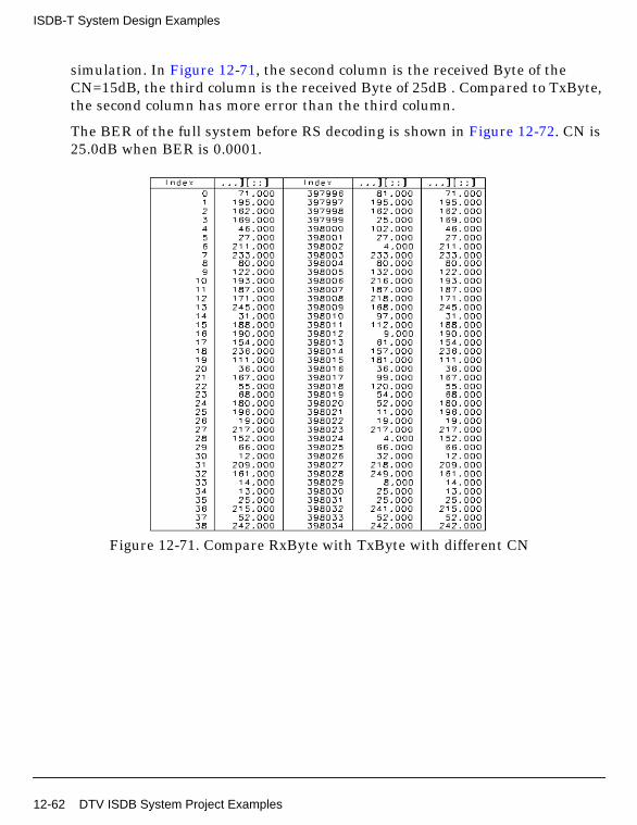
ISDB-T System Design Examples
simulation. In Figure 12-71, the second column is the received Byte of theCN=15dB, the third column is the received Byte of 25dB . Compared to TxByte,the second column has more error than the third column.
The BER of the full system before RS decoding is shown in Figure 12-72. CN is25.0dB when BER is 0.0001.
Figure 12-71. Compare RxByte with TxByte with different CN
12-62 DTV ISDB System Project Examples

Figure 12-72. Multipath Channel BER
• Multipath channel (10dB)
Measurements of BER vs. CN were made using a fading channel simulator. TheDU ratios of a main signal and a delayed signal were set to 10 dB. Delay time ofa delayed signal from a main signal was set to 1.5 us. This multipath channelhas no fading frequency. In the ADS simulation system, this multipath channelis simulated by UserDefChannel model, its parameters were set as follows:
This simulation result was not included into this DTV package because of thelimitation of DTV package size. If users want to prove the BER performance ofthis channel, users can set the parameters above and run this design example.The simulation time is very long.
Figure 12-73 show the transmitted Byte data and the received Byte data whencarrier-to-noise ratio (CN) is 15dB and 20dB in the multipath channelsimulation. In Figure 12-73, the second column is the received Byte of theCN=15dB, the third column is the received Byte of 20dB. Compared to TxByte,the second column has more errors than the the third column.
Symbol Specification Simulation Type Value
UserDefChannel PathNumber ADS Ptolemy 2
UserDefChannel AmpArray ADS Ptolemy “0.9535 0.3015”
UserDefChannel DelayArray ADS Ptolemy “0.0 1.5”
AntMobile Vx ADS Ptolemy 0
DTV ISDB System Project Examples 12-63

ISDB-T System Design Examples
The BER of the full system before RS decoding is shown in Figure 12-74. TheCN is 20.0dB when BER is 0.0001.
Figure 12-73. Compare RxByte with TxByte with different CN
12-64 DTV ISDB System Project Examples

Figure 12-74. Multipath Channel BER
Figure 12-75 shows the BERs of the three different simulation results. Theperformance of AWGN channel is better than the multipath channels (DUratios are 3dB and 10dB); the performance of the 10dB multipath channel isbetter than the 3dB multipath channel.
Figure 12-75. BERs of Different Channelssolid line = AWGN; dotted line =10dB multipath channel;
dot-dash line = 3dB multipath channel
DTV ISDB System Project Examples 12-65

ISDB-T System Design Examples
Benchmark
• Hardware Platform: Pentium II 200 MHz, 128 MB memory
• Software Platform: WindowsNT 4.0 Workstation, ADS 1.3
• Data Points: 188*5-1
• Simulation Time: 16 hours for AWGN channel, 20 hours for DU=3dB andDU=10 dB multipath channel.
References
[1]ARIB-JAPAN, “Terrestrial Integrated Services Digital Broadcasting (ISDB-T);Specification of Channel Coding, Framing Structure and Modulation,”Sept.1998.
12-66 DTV ISDB System Project Examples

1-Layer DQPSK-Mapping ISDB-T System Design
DTV_ISDBSystem_prj Design Name
DsnDTV_ISDBOneLay_DQPSK.dsn
Features
• 1-layer full ISDB system with channel coding/decoding and OFDMmodulation/demodulation
• OFDM modulation mode 1, 96 carriers per OFDM segment
• DQPSK mapping
• 1/2 rate punctured convolutional coding
• Reed-Solomon coding and decoding
• Bytewise interleaving, time and frequency interleaving
• Carrier rotation and scrambling
• AWGN, multipath, and Rayleigh fading channel simulations
Description
This design demonstrates the performance of a full 1-layer ISDB system, includingchannel coding/decoding and OFDM modulation/demodulation models. It uses OFDMmode 1 and OFDM modulation, DQPSK mapping, 1/2 rate punctured convolutionalcoding, interleaving and delay adjustments.
This design is simulated under AWGN, multipath, and Rayleigh fading channels. Thebit error rates of these channels are shown in the simulation results. In the AWGNchannel, the BER is compared to the DsnDTV_ISDBOFDM_DQPSK_BER.dsn designwithout channel coding and interleaving.
Schematics
Figure 12-76 shows the schematic for this design; the coding and decodingsubnetwork designs are shown in Figure 12-77 through Figure 12-80.
DTV ISDB System Project Examples 12-67

ISDB-T System Design Examples
Figure 12-76. DsnDTV_ISDBOneLay_DQPSK.dsn
Figure 12-77. sub_ISDBChCoder_DQPSK_1_2.dsn
Figure 12-78. sub_ISDBChDecoder_DQPSK_1_2.dsn
12-68 DTV ISDB System Project Examples

Figure 12-79. sub_ISDBOFDM_CohMod.dsn
Figure 12-80. sub_ISDBOFDM_CohDemod.dsn
Specifications
Notes
1. In this design, some system parameters are represented by global variables inorder to adapt the system to different modulation modes. These variables arelisted in Table 12-3.
2. Delay is introduced in the system in several places as listed in Table 12-4.
The following parameter settings are important as they relate to the delays inTable 12-4.
• In the DTV_PuncConvDecoder model, OFDM symbol and Viterbi decodingdelays are summed and adjusted to a multiple of 204 bytes in order tocorrectly align the data packet for Reed-Solomon decoding.
Symbol Specification Simulation Type Value
Number of carriers in each OFDM segment (mode 1) ADS Ptolemy 96
Number of OFDM segments in this layer ADS Ptolemy 13
Punctured convolutional code rate ADS Ptolemy 1/2
Constellation mapping ADS Ptolemy DQPSK
Vx Vehicle speed ADS Ptolemy 124 km/hr
DTV ISDB System Project Examples 12-69

ISDB-T System Design Examples
• In the sub_ISDBDerandomize subnetwork, delay parameters must be setcorrectly for the pseudo-random sequence to be reset at the right timing.
• The sink of the ultimate output of the system must take into account alldelays for correct output data that corresponds to system input.
Table 12-3. Global Variables
Variables Description
Carriers Number of carriers per segment in different OFDM modes:96, 192, or 384 for modes 1, 2, or 3, respectively.
Segments Number of OFDM segments belonging to this layer; in this 1-layer application, it is always 13.
NumberTSP Number of TSPs transmitted on all carriers of each OFDM segment. It is also determined by the data rate ofpunctured convolutional code type and constellation mapping.
FrameDelays Number of TSPs delayed in the entire system caused by byte interleaving (1 OFDM frame delay) and timeinterleaving (several OFDM frame delays, dependent on the I parameter of time interleaving. In this example,I=4; therefore, FrameDelays is 2 OFDM frames).
SymDelays Number of bytes delayed in the entire system caused by bit interleaving (2 OFDM symbols) and OFDMdemodulation (1 OFDM symbol).
CN Carrier/noise ratio of the channel.
Table 12-4.
Delay Type Delay Length
Byte interleaving and delay adjustment 1 OFDM frame
Bit interleaving and delay adjustment 2 OFDM symbols
Time interleaving and delay adjustment Several OFDM frames (depending on the time interleaving mode)
OFDM demodulation 1 OFDM symbol
Viterbi decoding several bytes determined by PathLen
12-70 DTV ISDB System Project Examples

Simulation Results
AWGN Channel
Additive white Gaussian noise was added to set the carrier-to-noise ratio (CN) at theinput of the receiver. Figure 12-81 shows the transmitted and the received byte datawhen carrier-to-noise ratio (CN) is 5dB and 7dB in the Gaussian channel simulation.
The BERs of the full system before RS decoding and OFDM system without channelcoding (in DsnDTV_ISDBOFDM_DQPSK_BER.dsn) are shown in Figure 12-82.From Figure 12-82, we can know the channel coding gain is about 8.0dB at 0.0001BER.
Figure 12-81. Compare RxByte with TxByte with different CN
DTV ISDB System Project Examples 12-71

ISDB-T System Design Examples
Figure 12-82. BER for AWGNFull System and OFDM System without Channel Coding
Multipath Channel
Measurements of BER vs. CN were made using a fading channel simulator. The DUratios of a main signal and a delayed signal were set to 3 dB. Delay time of a delayedsignal from a main signal was set to 1.5 µsec. This multipath channel has no fadingfrequency. In the ADS simulation system, this multipath channel is simulated byUserDefChannel model; parameters were set as follows.
Figure 12-83 shows the transmitted Byte data and the received Byte data whencarrier-to-noise ratio (CN) is 10dB and 13dB in the multipath channel simulation.
Symbol Specification Simulation Type Value
UserDefChannel PathNumber ADS Ptolemy 2
UserDefChannel AmpArray ADS Ptolemy “0.8165 0.5773”
UserDefChannel DelayArray ADS Ptolemy “0.0 1.5”
AntMobile Vx ADS Ptolemy 0
12-72 DTV ISDB System Project Examples

Figure 12-83. Compare RxByte with TxByte with different CN
The BER of the full system before RS decoding is shown in Figure 12-84. The CN is11.8dB when BER is 0.0002.
DTV ISDB System Project Examples 12-73

ISDB-T System Design Examples
Figure 12-84. Multipath Channel BER
Rayleigh Channel
Measurements of BER vs. CN were made using a fading channel simulator. 2-pathRayleigh fading was used and the DU ratio was set to 0 dB. Delay time of a delayedsignal from a main signal was set to 1.5 µsec. This multipath channel has a 70-Hzfading frequency. In the ADS simulation system, this multipath channel is simulatedby UserDefChannel model; parameters were set as follows:
Figure 12-85 shows the transmitted and received Byte data when carrier-to-noiseratio (CN) is 5dB and 15dB in the Rayleigh channel simulation. In Figure 12-85, thesecond column is the received Byte of the CN=5dB, the third column is the receivedByte of 15dB . Compared to TxByte, the second column has more errors than thethird.
Symbol Specification Simulation Type Value
UserDefChannel PathNumber ADS Ptolemy 2
UserDefChannel AmpArray ADS Ptolemy “0.707 0.707”
UserDefChannel DelayArray ADS Ptolemy “0.0 1.5”
AntMobile Vx ADS Ptolemy 124.0
12-74 DTV ISDB System Project Examples

Figure 12-85. Compare RxByte with TxByte with different CN
The BER of the full system before RS decoding is shown in Figure 12-86. The CN is14.5dB when BER is 0.0002.
DTV ISDB System Project Examples 12-75

ISDB-T System Design Examples
Figure 12-86. Rayleigh Channel BER
Benchmark
• Hardware Platform: Pentium II 200 MHz, 128 MB memory
• Software Platform: WindowsNT 4.0 Workstation, ADS 1.3
• Data Points: 2*188-1 Bytes
• Simulation Time: 16 hours for AWGN channel, 22 hours for multipath channel,40 hours for Rayleigh channel
References
[1]ARIB-JAPAN, “Terrestrial Integrated Services Digital Broadcasting (ISDB-T);Specification of Channel Coding, Framing Structure and Modulation,”Sept.1998.
12-76 DTV ISDB System Project Examples

3-Layer ISDB-T System Design
DTV_ISDBSystem_prj Design Name
DsnDTV_ISDBThrLay_System.dsn
Features
• 3-layer system design
• Different modulation mode and code rate for each layer
• Reed-Solomon coding and decoding
• Punctured convolutional coding and decoding
• Mode 1 OFDM adaptation
• Byte-wise interleaving and deinterleaving
• Time interleaving and deinterleaving
• Frequency interleaving and deinterleaving
Description
This design is a 3-layer system design example of ISDB-T. It includes 13 segments(1 segment for Layer A, 5 segments for Layer B, and 7 segments for Layer C). Themodulation modes and code rates are 64-QAM, 2/3, and DQPSK, 1/2, and 16-QAM,3/4 in Layer A, Layer B, and Layer C, respectively.
In the OFDM adaptation, the 3-layer full system design works in mode 1. The IFFT/FFT size is 2048; the guard interval is 1/16 of IFFT size. The simulation channel isthe TDMA channel. The byte in transmitter and receiver, the received 64-QAM,DQPSK, and 16-QAM constellations are shown in the simulation results.
Schematics
Figure 12-87 shows the schematic for this design; the subnetwork designs are shownin Figure 12-88 through Figure 12-93.
DTV ISDB System Project Examples 12-77

ISDB-T System Design Examples
Figure 12-87. DsnDTV_ISDBThrLay_System.dsn
Figure 12-88. sub_ISDBOFDM_ThrLayMod.dsn
12-78 DTV ISDB System Project Examples

Figure 12-89. sub_ISDBOFDM_ThrLayDemod.dsn
Figure 12-90. sub_ISDBThrLay_ChCoder.dsn
DTV ISDB System Project Examples 12-79

ISDB-T System Design Examples
Figure 12-91. sub_ISDBThrLay_ChDecoder.dsn
Figure 12-92. sub_ISDBThrLay_FreqInterlv.dsn
12-80 DTV ISDB System Project Examples

Figure 12-93. sub_ISDBThrLay_FreqDeinterlv.dsn
Specifications
Notes
1. The propagation channel model used in this example is a standard TDMAchannel.
Specification (Parameter) Simulation Type Value
Carriers ADS Ptolemy 96
Segments ADS Ptolemy 13
IFFTSize ADS Ptolemy 2048
FFTSize ADS Ptolemy 2048
Guard ADS Ptolemy 128
IFFTOrder ADS Ptolemy 11
FFTOrder ADS Ptolemy 11
MaxDelay ADS Ptolemy 2047
SegmentsA ADS Ptolemy 1
SegmentsB ADS Ptolemy 5
SegmentsC ADS Ptolemy 7
Ru ADS Ptolemy 0.9
DTV ISDB System Project Examples 12-81

ISDB-T System Design Examples
2. The DelayByte parameter of the punctured convolutional decoder model(DTV_PunConvDecoder) is used to adjust delays caused by OFDMdemodulation (which is one OFDM symbol) and two additional OFDM symboldelays, which correspond to the bit interleaving procedure because delayadjustment for bit interleaving is 2 OFDM symbols.
3. Total delay caused by byte-wise interleaving and deinterleaving is 17*11*12bytes (corresponding to 11 TSPs). Because the OFDM symbol is transmitted asan OFDM frame, delay of the TSPs is adjusted to one OFDM frame.
4. Total delay caused by time interleaving and deinterleaving is adjusted inaccordance with an integer I as shown in table 4-3 in ISDB-T. Because I=4 inthis 3-layer design, the number of OFDM frames to be delayed by the delayadjustment and time interleaving is 2.
5. The last delay adjusted in this design generates the number of total null TSPbytes which is needed per operation in DTV_SynThreeLayTSP model.
Simulation Results
Figure 12-94 shows the transmitted and received TSP data.
12-82 DTV ISDB System Project Examples

Figure 12-94. Compare RxTSP with TxTSP
Figure 12-95, Figure 12-96, and Figure 12-97 show the received constellations forLayers A, B, and C.
Figure 12-95. Received Constellation for Layer A
DTV ISDB System Project Examples 12-83

ISDB-T System Design Examples
Figure 12-96. Received Constellation for Layer B
Figure 12-97. Received Constellation for Layer C
Benchmark
• Hardware Platform: Pentium II 200 MHz, 128 MB memory
• Software Platform: WindowsNT 4.0 Workstation, ADS 1.3
• Data Points: 188*((12*5+36*7+48*1)*3+40) Bytes
• Simulation Time: 1 hour and 8 minutes
References
[1]ARIB-JAPAN, “Terrestrial Integrated Services Digital Broadcasting (ISDB-T);Specification of Channel Coding, Framing Structure and Modulation,”Sept.1998.
12-84 DTV ISDB System Project Examples

2-Layer ISDB-T System Design
DTV_ISDBSystem_prj Design Name
DsnDTV_ISDBTwoLay_System.dsn
Features
• 2- layer system design
• Different modulation mode and code rate for each layer
• Reed-Solomon coding and decoding
• Punctured convolutional coding and decoding
• Mode 1 OFDM adaptation
• Byte-wise interleaving and deinterleaving
• Time interleaving and deinterleaving
• Frequency interleaving and deinterleaving
Description
This design is a 2-layer system example of ISDB-T. It includes 13 segments (5segments for Layer A, 8 segments for Layer B). Modulation modes and code rates areDQPSK, 1/2, and 64-QAM, 7/8 in Layer A and Layer B, respectively.
In the OFDM adaptation, the 2-layer full system design works in mode 1. The IFFT/FFT size is 2048; the guard interval is 1/8 of IFFT size. The simulation channel is theTDMA channel. The byte in transmitter and receiver, the received DQPSK and64-QAM constellations are shown in the simulation results.
Schematics
Figure 12-98 shows the schematic for this design; the coding and decodingsubnetwork designs are shown in Figure 12-99 through Figure 12-104.
DTV ISDB System Project Examples 12-85

ISDB-T System Design Examples
Figure 12-98. DsnDTV_ISDBTwoLay_System.dsn
Figure 12-99. sub_ISDBOFDM_TwoLayMod.dsn
12-86 DTV ISDB System Project Examples

Figure 12-100. sub_ISDBOFDM_TwoLayDemod.dsn
Figure 12-101. sub_ISDBTwoLay_ChCoder.dsn
DTV ISDB System Project Examples 12-87

ISDB-T System Design Examples
Figure 12-102. sub_ISDBTwoLay_ChDecoder.dsn
Figure 12-103. sub_ISDBTwoLay_FreqInterlv.dsn
12-88 DTV ISDB System Project Examples

Figure 12-104. sub_ISDBTwoLay_FreqDeinterlv.dsn
Specifications
Notes
1. The propagation channel model used in this example is a standard TDMAchannel.
2. The DelayByte parameter of the punctured convolutional decoder model(DTV_PunConvDecoder) is used to adjust delays caused by OFDMdemodulation (which is one OFDM symbol) and two additional OFDM symbols
Specification (Parameter) Simulation Type Value
Carriers ADS Ptolemy 96
Segments ADS Ptolemy 13
IFFTSize ADS Ptolemy 2048
FFTSize ADS Ptolemy 2048
Guard ADS Ptolemy 256
IFFTOrder ADS Ptolemy 11
FFTOrder ADS Ptolemy 11
MaxDelay ADS Ptolemy 2047
SegmentsA ADS Ptolemy 5
SegmentsB ADS Ptolemy 8
Ru ADS Ptolemy 0.9
DTV ISDB System Project Examples 12-89

ISDB-T System Design Examples
delay which is corresponding to the bit interleaving procedure because delayadjustment for bit interleaving is 2 OFDM symbols.
3. Total delay caused by byte-wise interleaving and deinterleaving is 17*11*12bytes (corresponding to 11 TSPs). Because the OFDM symbol is transmitted asan OFDM frame, in this design the delay of the TSPs is adjusted to one OFDMframe.
4. Total delay caused by time interleaving and deinterleaving is adjusted inaccordance with an integer I as shown in table 4-3 in ISDB-T. Because I=4 inthis 2-layer design, the number of OFDM frames to be delayed by delayadjustment and time interleaving is 2.
5. The last delay adjusted in this design generates the number of total null TSPbytes which is needed per operation in DTV_SynTwoLayTSP model.
Simulation Results
Figure 12-105 shows the transmitted and received TSP data.
Figure 12-106 and Figure 12-107 show the received constellation of Layer A and B.
12-90 DTV ISDB System Project Examples

Figure 12-105. Compare RxTSP with TxTSP
Figure 12-106. Received Constellation for Layer A
DTV ISDB System Project Examples 12-91

ISDB-T System Design Examples
Figure 12-107. Received Constellation for Layer B
Benchmark
• Hardware Platform: Pentium II 200 MHz, 128 MB memory
• Software Platform: WindowsNT 4.0 Workstation, ADS 1.3
• Data Points: 188*((12*5+63*8)*3+47+47) Bytes
• Simulation Time: 1 hour and 26 minutes
References
[1]ARIB-JAPAN, “Terrestrial Integrated Services Digital Broadcasting (ISDB-T);Specification of Channel Coding, Framing Structure and Modulation,”Sept.1998.
12-92 DTV ISDB System Project Examples

TMCC in ISDB-T 1-Layer System Design
DTV_ISDBSystem_prj Design Name
DsnDTV_TMCCMod.dsn
Features
Displays include:
• TMCCInfoT (102 TMCC information bits in the transmitter)
• TMCCT (204 TMCC bits in the transmitter after channel coding)
• TMCCInfoR (102 TMCC information bits in the receiver after channeldecoding)
• TMCCR (204 TMCC bits in the receiver after TMCC modulation, AWGNchannel, and demodulation)
Description
This design example illustrates how to use TMCC models in ISDB-T 1-layer systems.It includes TMCC information multiplexing and de-multiplexing, channel coding anddecoding, and modulation and demodulation of TMCC carriers.
If the 1-layer ISDB-T system works in mode 3 and uses 13 segments, its modulationscheme of OFDM carrier is DQPSK, coding rate of inner code is 1/2, length of timeinterleaving is 2, then the first 122 TMCC bits should be
00 0 1 1 0 1 0 1 1 1 1 0 1 1 1 01 1 10 01 1 1 1000 0 00 0 00 1 01 1 0 11 1 11 1 11 1 11 1 1 11 1 1
DTV ISDB System Project Examples 12-93

ISDB-T System Design Examples
1 1 11 1 11 1 1 111 1 11 1 11 1 11 1 1 11 1 11 1 11 1 11 1 1 11 1 11 1 11 1 11 1 1 11 1 1 1 1 1 1 1 1 1 1 1 1 1 1
or
01 1 0 0 1 0 1 0 0 0 0 1 0 0 0 11 1 10 01 1 1 1000 0 00 0 00 1 01 1 0 11 1 11 1 11 1 11 1 1 11 1 11 1 11 1 11 1 1 111 1 11 1 11 1 1
12-94 DTV ISDB System Project Examples

1 1 1 11 1 11 1 11 1 11 1 1 11 1 11 1 11 1 11 1 1 11 1 1 1 1 1 1 1 1 1 1 1 1 1 1
We can compare the results of this design with the previous 122 TMCC bits in thedds file.
Schematics
Figure 12-108 shows the schematic for this design.
Figure 12-108. DsnDTV_TMCCMod.dsn
Simulation Results
Figure 12-109 shows the 102 TMCC information bits in the transmitter beforechannel coding and in the receiver after channel docoding. The first column is theinformation bits in the transmitter; the second column is the information bits in thereceiver; the third column is the error between the information bits.
DTV ISDB System Project Examples 12-95

ISDB-T System Design Examples
Figure 12-109. 102 TMCC information Bits in the Transmitter and Receiver
Figure 12-110 shows the 204 TMCC bits in the transmitter before modulation and inthe receiver after de-modulation. The first column is the transmitter bits; the secondcolumn is the receiver bits; the third column is the error between the informationbits.
12-96 DTV ISDB System Project Examples

Figure 12-110. 204 TMCC bits in the Transmitter and Receiver
Benchmark
• Hardware Platform: Pentium III 450 MHz, 512 MB memory
• Software Platform: Windows NT 4.0 Workstation, ADS 1.3
• Data Points: 408
• Simulation Time: 5 seconds
References
[1]ARIB-JAPAN, “Terrestrial Integrated Services Digital Broadcasting (ISDB-T);Specification of Channel Coding, Framing Structure and Modulation,”Sept.1998.
DTV ISDB System Project Examples 12-97

ISDB-T System Design Examples
TMCC in ISDB-T 3-Layer System Design
DTV_ISDBSystem_prj Design Name
DsnDTV_TMCCThrLay.dsn
Features
Displays include:
• TMCCInfoT (102 TMCC information bits in the transmitter)
• TMCCT 204 TMCC bits in the transmitter after channel coding)
• TMCCInfoR (102 TMCC information bits in the receiver after channeldecoding)
• TMCCR (204 TMCC bits in the receiver after TMCC modulation, AWGNchannel, and demodulation)
Description
This design example illustrates how to use TMCC models in ISDB-T 3-layer systems.It includes TMCC information multiplexing and de-multiplexing, channel coding anddecoding, and modulation and demodulation of TMCC carriers.
Schematics
Figure 12-111 shows the schematic for this design.
12-98 DTV ISDB System Project Examples

Figure 12-111. DsnDTV_TMCCThrLay.dsn
Simulation Results
Figure 12-112 lists the 102 bits TMCC information bits in the transmitter beforechannel coding and in the receiver after channel docoding. The first column is the 102TMCC information bits in the transmitter; the second column is the 102 informationbits in the receiver; the third column is the error between both 102 TMCCinformation bits.
Figure 12-113 shows the 204 bits TMCC bits in the transmitter before modulator andin the receiver after de-modulator. The first column is the 204 TMCC bits in thetransmitter, the second column is the 204 TMCC bits in the receiver, and the thirdcolumn is the error between both 204 TMCC information bits.
DTV ISDB System Project Examples 12-99
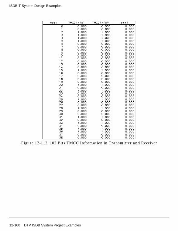
ISDB-T System Design Examples
Figure 12-112. 102 Bits TMCC Information in Transmitter and Receiver
12-100 DTV ISDB System Project Examples

Figure 12-113. 204 TMCC Bits in Transmitter and Receiver
Benchmark
• Hardware Platform: Pentium III 450 MHz, 512 MB memory
• Software Platform: Windows NT 4.0 Workstation, ADS 1.3
• Data Points: 408
• Simulation Time: 5 seconds
References
[1]ARIB-JAPAN, “Terrestrial Integrated Services Digital Broadcasting (ISDB-T);Specification of Channel Coding, Framing Structure and Modulation,”Sept.1998.
DTV ISDB System Project Examples 12-101

ISDB-T System Design Examples
12-102 DTV ISDB System Project Examples

Index
AAddFixPhase, 7-2BBCHCoder, 2-2BCHDecoder, 2-5BER, 8-2
CCarrierRotator, 5-6CarrierScrambler, 5-8CDSCDecoder, 5-2ChEstimator, 5-13CIRNorm, 4-2CommCtrl2, 6-2CommCtrl3, 6-3ConvCoder, 2-10ConvCoder1_2, 2-12ConvDecoder, 2-14ConvDecoder1_2, 2-17
DDelay, 2-19Demapper, 2-20DemuxCohSegs, 5-18DemuxDiffSegs, 5-24DemuxTMCC, 5-31DistCtrl2, 6-4DistCtrl3, 6-5DQPSKCoder, 2-23DQPSKDecoder, 2-25DVB2DChEstimator, 4-4DVBBitBlockInterlv, 4-9DVBChannel, 4-11DVBChEstimator, 4-14DVBDemuxOFDMSym, 4-18DVBHHierReceiver, 3-2DVBHHierReceiver_RF, 3-9DVBHHierSignalSrc, 3-17DVBHHierSignalSrc_RF, 3-22DVBHInnerDeinterlv, 3-29DVBHInnerInterlv, 3-36DVBHReceiver, 3-43DVBHReceiver_RF, 3-48DVBHSignalSrc, 3-54
DVBHSignalSrc_RF, 3-58DVBHTPS, 3-64DVBLoadIFFTBuff, 4-23DVBMuxOFDMSym, 4-25DVBSymDeinterlv2b, 4-29DVBSymDeinterlv4b, 4-31DVBSymDeinterlv6b, 4-33DVBSymInterlv2b, 4-35DVBSymInterlv4b, 4-39DVBSymInterlv6b, 4-41DVBSymInterlvCx, 4-43DVBTHierInnerDeInterlv, 4-45DVBTHierInnerInterlv, 4-47DVBTHierReceiver, 4-49DVBTHierReceiver_RF, 4-56DVBTHierSignalSrc, 4-65DVBTHierSignalSrc_RF, 4-70DVBTImpulseNoise, 4-76DVBTInnerDeInterlv, 4-79DVBTInnerInterlv, 4-81DVBTOFDMDemod, 4-83DVBTOFDMMod, 4-88DVBTPS, 4-93DVBTPSDemod, 4-97DVBTPSMod, 4-99DVBTReceiver, 4-101DVBTReceiver_RF, 4-107DVBTSignalSrc, 4-114DVBTSignalSrc_RF, 4-118DVBTTPSGen, 4-124DVBTTSPsource, 4-130
IInnerDecoder, 2-27InsertGuard, 7-4InterlvFloat, 2-29InterlvInt, 2-31InterSegInterlv, 5-33ISDBChCoder, 2-34ISDBChDecoder, 2-36ISDBDemodulation, 5-35ISDBDerandomize, 2-38ISDBFreqDeinterlv, 5-38ISDBFreqInterlv, 5-40ISDBModulation, 5-62
Index-1

ISDBMuxSegs, 5-78ISDBOFDMDemod_OneLay, 5-80ISDBOFDMDemod_ThreeLay, 5-42ISDBOFDMDemod_TwoLay, 5-45ISDBOFDMMod_OneLay, 5-83ISDBOFDMMod_ThreeLay, 5-48ISDBOFDMMod_TwoLay, 5-53ISDBOneLayReceiver, 5-85ISDBOneLayReceiver_RF, 5-90ISDBOneLaySource, 5-96ISDBOneLaySource_RF, 5-100ISDBPartialReceiver_RF, 5-106ISDBRandomize, 2-40ISDBThreeLayReceiver, 5-121ISDBThreeLayReceiver_RF, 5-127ISDBThreeLaySource, 5-134ISDBThreeLaySource_RF, 5-138ISDBTimeInterlv, 5-144ISDBTMCC, 5-111ISDBTSPSource, 5-119ISDBTwoLayFreqDeinterlv, 5-146ISDBTwoLayFreqInterlv, 5-148ISDBTwoLayReceiver, 5-150ISDBTwoLayReceiver_RF, 5-155ISDBTwoLaySource, 5-161ISDBTwoLaySource_RF, 5-165
LLFSRCoder, 5-57LoadFFTBuff, 7-6LoadIFFTBuff, 5-60
MMapper, 2-43MLEstimator, 7-11MuxCohSegs, 5-65MuxDiffSegs, 5-71
OOFDMEqualizer, 7-14
PPackTMCC, 5-171PALSource, 4-133PNreset, 2-49PowerMeasure, 8-4PuncCoder, 2-51PuncConvCoder, 2-53
PuncConvDecoder, 2-55PuncDecoder, 2-58
QQAM16Coder, 2-60QAM16Decoder, 2-63QAM64Coder, 2-65QAM64Decoder, 2-69QPSKCoder, 2-71QPSKDecoder, 2-73
RRemovePhase, 7-16RSCoder, 2-74RSDecoder, 2-78
SScrambleByte, 2-84SplitThreeLayData, 6-6SplitThreeLayTSP, 6-8SplitTwoLayData, 6-11SplitTwoLayTSP, 6-13SynLayTMCC1, 6-16SynLayTMCC2, 6-18SynLayTMCC3, 6-20SynThreeLayData, 6-22SynThreeLayTSP, 6-24SynTwoLayData, 6-27SynTwoLayTSP, 6-29
TTimeInterlv, 5-187TMCCDemod, 5-173TMCCInfo, 5-175TMCCMod, 5-185
Index-2