Embed Size (px)
Citation preview

DTP1 GATE OPENER INSTALLATION AND OWNERS MANUAL
5004019CONFORMS TO UL STD 325
WARNING: This product can expose you to chemicals including lead, which is known to the State of California to cause cancer. For more information, go to www.P65Warnings.ca.gov
www.GhostControls.com 2017-09 DTP1IM
LIMITED LIFETIME WARRANTY ON MOTOR AND GEAR ASSEMBLY!

PAGE LEFT BLANK

3D T P 1 O p e n e r K i t
© G h o s t C o n t r o l s 2 0 1 7 | w w w . G h o s t C o n t r o l s . c o m
5 Read This First Important SAFETY Instructions
7 Specifications 9 System Safety13 Tools And Supplies Needed15 DTP1 Kit Site Planning19 Install Operator
PULL-TO-OPEN SYSTEMS
31 Install Operator PUSH-TO-OPEN SYSTEMS
43 Installing Control Box47 Installing Battery Box51 Preparing The Gate System Controller
Pull-To-Open and Push-To-Open Applications
55 Programming The Gate System Controller58 Troubleshooting Guide59 Connecting Optional Accessories61 Manual Gate Operation
Every User Must Know These Steps
62 Accessories63 Warranty
C O N T E N T S INSTALLATION AND OWNERS MANUAL

PAGE LEFT BLANK

5R E A D M E F I R S T
© G h o s t C o n t r o l s 2 0 1 7 | w w w . G h o s t C o n t r o l s . c o m
1 . This gate operator is only intended for use on gates intended for vehicular access and is not intended for pedestrian gate applications. Pedestrians must use a separate entrance.
2 . The GHOST CONTROLS® Automatic Gate Opener can be installed on a pull-to-open application with the items included in the kit. For push-to-open applications you will need to purchase two (2) Push-To-Open (item AXPO) bracket kits (required) from your local retailer. If they do not have the bracket kit then please visit https://www.ghostcontrols.com/shop or contact GHOST CONTROLS® Technical Support (850-898-1411) to purchase.
3 . This GHOST CONTROLS® Automatic Gate Opener features a patent-pending SafeForce® power limiting feature that doesn’t require additional Photo Eyes for entrapment protection in most applications of a properly installed gate. During installation, you may instead choose to use external monitored safety devices such as non-contact photo eyes (item AXPE sold separately) and will need to enable this setting on the main system controller during setup.
4. The operator can be used on a variety of gate types, but should not be used on solid or wood panel gates. Solid panel gates have a higher likelihood to experi-ence problems due to their higher resistance to wind and may result in faulty operation of the automatic gate operator.
5 . All GHOST CONTROLS® Automatic Gate Operators include automatic reversing safety features that will make the gates stop and reverse direction within 2 seconds of encountering an obstruction. There is a manual setting on the main gate operator control board labeled Force Setting that adjusts the sensitivity of this feature.
6 . This GHOST CONTROLS® Automatic Gate Operator can be enhanced with additional GHOST CONTROLS® accessories such as our remote transmitters, keypads, and all other accessories, sold separately. (Accessories see page 62). The GHOST CONTROLS® technical support team is happy to assist in verifying compatibility of any products not offered by GHOST CONTROLS®. For additional assistance, please contact GHOST CONTROLS® Technical support https://ghostcon-trols.support.com or by calling 850-898-1411.
7. Check all local building codes and ordinances prior to installing this automatic gate operator system to make sure your planned installation is in compliance.
8 . Your gate must be in good working condition before installation of the automatic gate operator system and meet the following criteria:
A. Gate should not use wheels for support or drag along the ground at any point in the opening or closing cycle.
READ THIS FIRST IMPORTANT SAFETY INSTRUCTIONS
Thank you for choosing a GHOST CONTROLS® Automatic Gate Opener system, the most innovative gate opener systems available for residential applications on the market today. This manual will guide you through the proper instal-lation and maintenance methods. To reduce the risk of injury or death: READ, UNDERSTAND, AND FOLLOW ALL INSTRUCTIONS CAREFULLY AND COMPLETELY. Following these directions is critical to a successful and safe operating environment.

6 R E A D M E F I R S T
© G h o s t C o n t r o l s 2 0 1 7 | w w w . G h o s t C o n t r o l s . c o m
B. Gate should be completely supported by mount-ing hinges. It may be necessary to add additional hinges to some gate installations.
C. Gate should be level, plumb, and move freely in both directions when minimal force is applied in the opening or closing direction.
D. Gate should NOT open uphill or downhill.
9. The vehicular entry gate system must be installed in a location that prevents entrapment by providing sufficient clearance between it and adjacent structures when opening and closing.
10. Never let children operate or play with gate controls. Keep the remote control away from children.
11. When planning a system that will allow entry from a busy road or highway, make sure the system is placed far enough from the road to prevent traffic congestion.
12. Swing gate systems must not open into public access areas or into the road which could cause collision with a moving vehicle.
13. Test the gate operator monthly. The gate MUST reverse on contact with a rigid object or stop when an object activates the non-contact sensors. After adjusting the force or the limit of travel, retest the gate operator. Failure to adjust and retest the gate operator properly can increase the risk of injury or death.
14. KEEP GATES PROPERLY MAINTAINED. Read the user’s manual. Have a qualified service person make repairs to gate hardware.
15. SAVE THESE INSTRUCTIONS.

7S P E C I F I C A T I O N S
© G h o s t C o n t r o l s 2 0 1 7 | w w w . G h o s t C o n t r o l s . c o m
SPECIFICATIONS ■ Compliance: The operator is system certified to be in compliance with
UL325 6th Edition Standards ■ System Operating Voltage: 12 VDC ■ System Battery Type: Battery Box Kit (ABBT) included ■ System Current: 1-2 Amps is typical when active.
Standby is 20 milliamperes ■ Operator Arm Maximum Stroke Distance: 23 Inches ■ Maximum Gate Length: 20’ ■ Operator Opening Speed: 90 degrees in approximately 15 seconds ■ Maximum Operator Opening Range: 110 degrees ■ Linear Actuator Operating Temperature: -5°F to 160°F
SPECIFICATIONS DTP1 GATE OPERATOR KIT

8 S P E C I F I C A T I O N S
© G h o s t C o n t r o l s 2 0 1 7 | w w w . G h o s t C o n t r o l s . c o m
PAGE LEFT BLANK

9S Y S T E M S A F E T Y
© G h o s t C o n t r o l s 2 0 1 7 | w w w . G h o s t C o n t r o l s . c o m
This manual contains important safety precautions and warnings for both the installer and end users or consumers of this automatic gate opener system. The following warn-ings and safety are intended to apply to the most common applications but may not apply to all possible installation and applications for these products. To reduce risk of injury or death:1 . CAREFULLY READ AND FOLLOW ALL SAFETY
PRECAUTIONS, WARNINGS, INSTALLATION AND OPERATING INSTRUCTIONS.
2 . DO NOT ALLOW CHILDREN TO OPERATE GATE CONTROLS. Do not allow children or pets to play near the gate opener system. Keep all gate control accessories such as remote transmitters, keypads, and push buttons out of reach of children and store in a secure area when not in use.
3 . Understand how to disconnect the power and manually open the gate (beginning on page 61) BEFORE you begin using the gate opener system. If you are unsure of any of these steps, please contact GHOST CONTROLS® Technical Support at 850-898-1411 or online at https://ghostcontrols.support.com.
4 . Disconnect the gate operator from the gate only when the gate is not in motion and the opener system is turned off.
5 . Moving gates can be dangerous. No one, including people or animals, should cross the path of a moving gate. Maintain a safe distance from moving parts and avoid any areas where hands or fingers could be pinched.
6 . Become familiar with potential entrapment zones as shown in diagram and avoid these areas when the gate is turned on.
7. The gate opener system must be installed only in applications that it is specifically designed for including: frequency of use, length, and weight of the gate.
8 . The gate opener system and installation must comply with any applicable local codes.
9. Install the gate operator system on the inside of the property, gate, or fence line to prevent public access to it. Most applications are installed in a pull-to-open configuration so that the gate opens into the property and away from any public roads.
10. The control board for the gate operator system should be protected from unauthorized access inside the con-trol box to prevent tampering or adjustments to its set-ting once installed. The control box is designed so that a lock can be attached to keep the box securely closed. An accessory Operator Security Lock Kit (AX3L) is available for purchase that includes a lock for the con-trol box, battery box, along with a replacement clevis pin and lock to secure the operator to the gate itself.
11 . Keypads and push-buttons to activate the gate opera-tor system must be a minimum of 10’ away in direct line of sight visibility to the gate so that the user can verify that any potential entrapment areas are clear of potential obstructions.
Grey Indicates PotentialEntrapement Areas
OPTIONALPHOTO BEAM
OPTIONAL PHOTO BEAM
OPTIONAL PHOTO BEAM OPTIONAL PHOTO BEAM
OPTIONAL PHOTO BEAM
OPTIONALPHOTO BEAM
SYSTEM SAFETY GATE OPENER SYSTEMS

10 S Y S T E M S A F E T Y
© G h o s t C o n t r o l s 2 0 1 7 | w w w . G h o s t C o n t r o l s . c o m
12 . The included warning signs must be attached to each side of the gate to alert the public of the auto-matic gate operator system. Please contact GHOST CONTROLS® Technical Support for replacement signs if yours become damaged.
13 . While the gate is moving do not drive into the gate area to prevent entrapment and potential damage to your vehicle, gate, AND the gate opener system.
14 . Do not attempt to “race the gate” by driving through the gate while it is opening or closing. This is extremely dangerous and can cause damage to your vehicle, gate, AND the gate opener system.
15 . Maintain the gate and the gate opener system to make sure that the gate continues to swing freely and is level throughout the entire swing path. The gate hinges should be lubricated regularly, the condition of the battery checked every few months, and all connections checked no less than an annual basis.
16 . In the event that you sell the gate opener system or your property with a system installed, please provide these instructions to the new owners. The most recent version of these instructions can be found on our support website at https://ghostcontrols.support.com.
VEHICULAR GATE STANDARD We recommend that all vehicular gates be constructed and installed in accordance with Active Standard ASTM F2200, Standard Specification for Automated Vehicular Gate Construction. For more information on this stan-dard, contact ASTM directly at http://www.astm.org/Standards/F2200.htm.
WARNING SIGNS The included warning signs must be installed on both the inside and outside of the gate.
! !
©GHOST CONTROLS 2016
1. Persons are to keep clear! The gate is able to be moved without prior warning.
2. DO NOT let children operate the gare or play in the gate area.
3. Persons are to operate the gate only when the gate area is in sight and free of people and obstructions.
4. Persons are to read the user’s manual and safety instructions.
WARNING

11S Y S T E M S A F E T Y
© G h o s t C o n t r o l s 2 0 1 7 | w w w . G h o s t C o n t r o l s . c o m
SWING GATE PROTECTION AND ENTRAPMENT ZONES As specified in Gate Operator Safety Standard, UL325 (30A 1.1) 6th Edition, all gate operators must include two independent means of entrapment protection. All GHOST CONTROLS® Automatic Gate opener systems meet this standard as indicated on the product packaging through the following:
1 . TYPE A Inherent.
2 . Number one above AND either of the following two options:A. TYPE C Inherent force limiting.A. TYPE B1 and B2 monitored contact and non-
contact sensors.
If you have questions about compatibility of third party safety devices, please contact GHOST CONTROLS® technical support for assistance at http://ghostcontrols.support.com.
Refer to the monitored photo eye instructions for proper placement of the sensors. Proper installation of these sensors is critical to avoid false tripping while gate is in motion and to reduce potential entrapment.
CAUTION Extreme caution must be exercised when automatic gate opener system is in operation, regardless of which safety systems are installed and in use.
ALARMYour GHOST CONTROLS® Gate Operator system includes an audible alarm. This alarm will continue to sound for 5 minutes when two sequential obstructions are detected during gate travel per UL325 safety standards or until one of the following occurs:
■ The gate operator receives an intended signal from a hard wired entry/exit source such as a push button or a wired keypad. Note that wireless transmitters and wireless keypads cannot deactivate the alarm.
■ The gate operator system is powered off and then on again at the main power switch in the control box.
NOTE The alarm may also be used as audio feedback for other modes of operation under normal operation.

12 S Y S T E M S A F E T Y
© G h o s t C o n t r o l s 2 0 1 7 | w w w . G h o s t C o n t r o l s . c o m
ENTRAPMENT AREA NOTESBetween gate and post Keep hands, feet, and pets away from this area when gate is in motion.Pinch point between opener and gate Keep hands, feet, and pets away from this area when gate is in motion.Path of the moving gate All one zoneLeading edge of gate and pinch point between gates in a dual gate installation
The leading edge of the gate in motion can easily cause injury to people, pets, or livestock, and will damage property including vehicles if it comes into contact with them.

13T O O L S N E E D E D
G h o s t C o n t r o l s 2 0 1 7 | w w w . G h o s t C o n t r o l s . c o m
25'
Wire Strippers/Cutters
Level
Phillips HeadScrewdriver
9/16" Drill BitLonger thanDiameter or
Thickness of Post
Corded/CordlessDrill
Standard or Metric Wrench
Tape Measure
1/2" DrillBit
Standard or MetricSocket Set
INSTALLING THE OPERATOR TOOLS AND SUPPLIES NEEDED

14 D T P 1 K I T
G h o s t C o n t r o l s 2 0 1 7 | w w w . G h o s t C o n t r o l s . c o m
PARTS INCLUDED IN KIT
Front Mount Hardware
Rear Mount Hardware
Gate Mount Hardware
Gate and FrontMount Hardware
Post and Rear Mount Hardware
Estate Bracket (Qty 1)
PBK6BA

15P L A N N I N G
© G H O S T C O N T R O L S 2 0 1 7 | w w w . G h o s t C o n t r o l s . c o m
Gate Lock Tube Gate Brackets
Push Button
Wired Vehicle Sensor
5 ButtonTransmitter(included)
3 ButtonTransmitter(optional)
Minium of 20 Feet
ControlBoxSolar Panel Battery
Box Kit
PedestrianGate
Wireless Keypad
Outdoor Mounting Pedestal
Proper planning of the automatic gate operator installation will enable a successful installation for almost anyone who has general home improvement skills. You should consider the following:
1 . SEPARATE PEDESTRIAN GATE IS REQUIRED!
2 . Single or dual gate operation based on the size of your opening, gate specifications, and operator system capacities.A. Dual gate operations require trenching across the
driveway so that the power cable for the secondary gate operator can be buried.
B. The power cable should always be enclosed in PVC conduit for protection, including when buried across the driveway in dual gate applications.
3 . Swing direction of gate(s). The image (shown) indicates the more common “Pull-To-Open” installation and the less common “Push-To-Open” installation.
Gate Operator System View Looking Straight Down from Above
PULL-TO-OPENMost Common
PUSH-TO-OPEN
Diagram also shows optional add-on accessories available for your gate opener system
INSTALLATION PLANNING DTP1 KIT SITE PLANNING

16 D T P 1 K I T
© G h o s t C o n t r o l s 2 0 1 7 | w w w . G h o s t C o n t r o l s . c o m
NOTE Push-to-Open installations REQUIRE an accessory Push-to-Open bracket kit (AXPO). DUAL applications require two (2) AXPO kits.
4 . Mounting location on gate and support post, column, or wall.A. Wooden posts should be at least 6x6 in size.B. Metal posts should be at least 4x4 in size.C. Additional mounting bolts may be required if the included bolts are not at least 1” longer than the diameter
of the post.
5 . Location and mounting point of control box and battery box.
6 . Power source to charge the battery (Solar Power vs. AC Power via transformer)A. Never use Solar Panels and an AC transformer on a gate system at the same time or you will damage the
main control board and void any warranty.B. The AC transformer is designed for indoor use and must be protected in a weather resistant box (that
meets code in your area) if it will be mounted outside.
7. If choosing to use an AC transformer for the battery recharging power source, you should consider the distance from an outlet to your battery box.A. No more than 1000 feet of low voltage wire may be used between the AC transformer and the gate
operator system due to electrical losses. If your application exceeds 1000 feet in distance, you must use Solar Panels for your power source to recharge the batteries.
B. Wire will need to be purchased separately. AXLV 100’ Low Voltage Wire is available as an accessory.C. The transformer should be on a circuit that is protected by a GFCI plug or breaker.
8 . How to exit the property and trigger opening operation of the gate (push button, remote transmitter, keypad, or vehicle exit wand).

17P L A N N I N G
© G H O S T C O N T R O L S 2 0 1 7 | w w w . G h o s t C o n t r o l s . c o m
9. Number of hours of direct sunlight available for solar applications.A. Please check the following for your locations potential solar energy available. http://energy.gov/maps/
solar-energy-potentialB. Determine the number of expected winter cycles for a single gate using solar power by reviewing map and
chart shown.
PREPARE THE GATE Proper installation, care, and ongoing maintenance of the gate is critical to increased usage life of the automatic gate operator system. The following items should be considered and addressed if needed PRIOR to installation of the automatic gate operator system:
1 . The gate must swing freely throughout its entire range of motion remaining plumb and level. The gate should not swing uphill or downhill when opening or closing.
LEVEL
CONCRETE THE POSTS IN THE GROUND
A MAXIMUM OF 3 AXDP 10-WATT SOLAR PANELS OR NO MORE THAN 30-WATTS OF SOLAR POWER SHOULD BE CONNECTED TO ANY GHOST CONTROLS SYSTEM CONTROL BOARD.

18 D T P 1 K I T
© G h o s t C o n t r o l s 2 0 1 7 | w w w . G h o s t C o n t r o l s . c o m
2 . The gate must not drag on the ground at any point during its motion and must not be supported by rollers or wheels.
3 . Extremely heavy gates that exceed 200 lbs in weight per leaf should be mounted with ball bearing hinges that include grease fittings.
4 . The gate should be mounted to a very stable post or column that is secured in the ground with concrete. Securing the post with concrete reduces the twisting effect that the torque of the gate places on the mounting post/column when moving through its range of motion. Installation is not recommended on any post or column that is not installed in the ground with concrete.
5 . The front mount of the gate operator should be attached to the gate securely. This may require modifications to the gate design or surface to maintain this secure mounting location.
DETERMINE MOUNTING LOCATION ON GATE AND SUPPORT BARYou must determine where to mount the gate operator vertically on your gate system.
■ Top Mounting — The gate operator is not recommended to be mounted to the top of the gate because the operator may cause twisting or flexing of the gate while in motion.
■ Center Line Mounting — This is the most common and recom-mended method for mounting an operator to the gate system. Mount as close to center as feasible.
■ Bottom Mounting — The gate operator must be mounted high enough off of the ground so that it does not come in contact with standing or flowing water which will damage the system. This mounting location may cause undesirable twisting or flexing of the gate while in motion.
OPERATOR REAR MOUNT INSTALLATION CONSIDERATIONSThe GHOST CONTROLS® Automatic Gate Operator system is designed for installation on rectangular, square, or round posts or columns. The rear bracket must be level and secured to the mounting post or column with bolts, nuts, and washers because this bracket will experience a tremendous amount of force during operation of the automatic gate operator. Proper positioning of the rear mounting bracket is critical because it determines:
■ Leverage and stability of the operator as it applies force to move the gate ■ Necessary clearance between the operator in both the closed and open positions.
Top Mount
Center Mount
Bottom Mount
19P U L L - T O - O P E N
G h o s t C o n t r o l s 2 0 1 7 | w w w . G h o s t C o n t r o l s . c o m
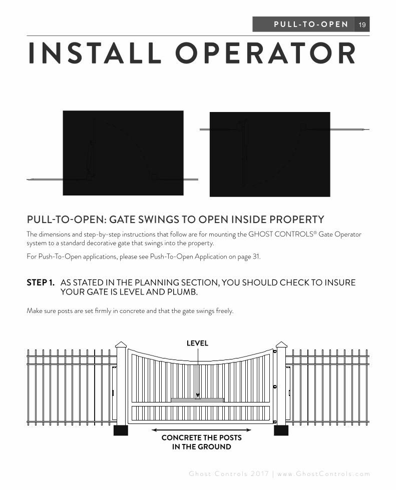
PULL-TO-OPEN: GATE SWINGS TO OPEN INSIDE PROPERTYThe dimensions and step-by-step instructions that follow are for mounting the GHOST CONTROLS® Gate Operator system to a standard decorative gate that swings into the property.
For Push-To-Open applications, please see Push-To-Open Application on page 31.
STEP 1. AS STATED IN THE PLANNING SECTION, YOU SHOULD CHECK TO INSURE YOUR GATE IS LEVEL AND PLUMB.
Make sure posts are set firmly in concrete and that the gate swings freely.
LEVEL
CONCRETE THE POSTS IN THE GROUND
I N S TA L L O P E R AT O R
20 D T P 1 K I T
G h o s t C o n t r o l s 2 0 1 7 | w w w . G h o s t C o n t r o l s . c o m
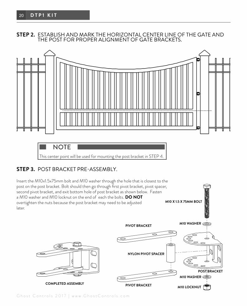
STEP 2. ESTABLISH AND MARK THE HORIZONTAL CENTER LINE OF THE GATE AND THE POST FOR PROPER ALIGNMENT OF GATE BRACKETS.
NOTE This center point will be used for mounting the post bracket in STEP 4.
STEP 3. POST BRACKET PRE-ASSEMBLY.
Insert the M10x1.5x75mm bolt and M10 washer through the hole that is closest to the post on the post bracket. Bolt should then go through first pivot bracket, pivot spacer, second pivot bracket, and exit bottom hole of post bracket as shown below. Fasten a M10 washer and M10 locknut on the end of each the bolts. DO NOT overtighten the nuts because the post bracket may need to be adjusted later.
PIVOT BRACKET
PIVOT BRACKET
NYLON PIVOT SPACER
COMPLETED ASSEMBLY
M10 X 1.5 X 75MM BOLT
M10 WASHER
M10 WASHER
M10 LOCKNUT
POST BRACKET

21P U L L - T O - O P E N
G h o s t C o n t r o l s 2 0 1 7 | w w w . G h o s t C o n t r o l s . c o m
STEP 2. ESTABLISH AND MARK THE HORIZONTAL CENTER LINE OF THE GATE AND THE POST FOR PROPER ALIGNMENT OF GATE BRACKETS.
NOTE This center point will be used for mounting the post bracket in STEP 4.
STEP 3. POST BRACKET PRE-ASSEMBLY.
Insert the M10x1.5x75mm bolt and M10 washer through the hole that is closest to the post on the post bracket. Bolt should then go through first pivot bracket, pivot spacer, second pivot bracket, and exit bottom hole of post bracket as shown below. Fasten a M10 washer and M10 locknut on the end of each the bolts. DO NOT overtighten the nuts because the post bracket may need to be adjusted later.
PIVOT BRACKET
PIVOT BRACKET
NYLON PIVOT SPACER
COMPLETED ASSEMBLY
M10 X 1.5 X 75MM BOLT
M10 WASHER
M10 WASHER
M10 LOCKNUT
POST BRACKET
STEP 4. CLAMPING POST BRACKET TO POST.
After the post bracket is pre-assembled and the horizontal centerline has been marked on the post as referred to in Step 2 and 3, then proceed to clamp the post bracket to the marked centerline on the post.
NOTE For round post installations we recommend notching the post for proper installation of the post bracket.

22 D T P 1 K I T
G h o s t C o n t r o l s 2 0 1 7 | w w w . G h o s t C o n t r o l s . c o m
STEP 5. VERIFYING GATE CLEARANCE. GATE MUST BE IN FULLY OPEN POSITION.
NOTE Gate must be in the FULLY OPEN POSITION before checking for proper clearance.
Clearance must begreater than 4.5"
Top View of Fence
Top View of Gate
Top View of Fence
ADJUST PIVOT BRACKET ON POST AS NEEDED
23P U L L - T O - O P E N
G h o s t C o n t r o l s 2 0 1 7 | w w w . G h o s t C o n t r o l s . c o m
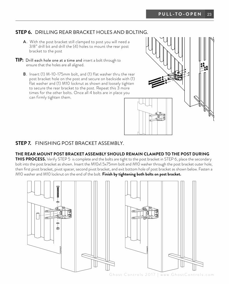
STEP 6. DRILLING REAR BRACKET HOLES AND BOLTING.
A . With the post bracket still clamped to post you will need a 3/8” drill bit and drill the (4) holes to mount the rear post bracket to the post
TIP: Drill each hole one at a time and insert a bolt through to ensure that the holes are all aligned.
B. Insert (1) M-10-175mm bolt, and (1) flat washer thru the rear post bracket hole on the post and secure on backside with (1) flat washer and (1) M10 locknut as shown and loosely tighten to secure the rear bracket to the post. Repeat this 3 more times for the other bolts. Once all 4 bolts are in place you can firmly tighten them.
STEP 7. FINISHING POST BRACKET ASSEMBLY.
THE REAR MOUNT POST BRACKET ASSEMBLY SHOULD REMAIN CLAMPED TO THE POST DURING THIS PROCESS. Verify STEP 5 is complete and the bolts are tight to the post bracket in STEP 6, place the secondary bolt into the post bracket as shown. Insert the M10x1.5x75mm bolt and M10 washer through the post bracket outer hole, then first pivot bracket, pivot spacer, second pivot bracket, and exit bottom hole of post bracket as shown below. Fasten a M10 washer and M10 locknut on the end of the bolt. Finish by tightening both bolts on post bracket.

24 D T P 1 K I T
G h o s t C o n t r o l s 2 0 1 7 | w w w . G h o s t C o n t r o l s . c o m
STEP 8. HANGING OPERATOR ON REAR MOUNT.
Insert clevis pin, nylon spacer and clevis hairpin as shown below to secure the rear of the operator to the post.
25P U L L - T O - O P E N
G h o s t C o n t r o l s 2 0 1 7 | w w w . G h o s t C o n t r o l s . c o m
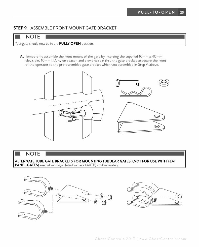
STEP 9. ASSEMBLE FRONT MOUNT GATE BRACKET.
NOTE Your gate should now be in the FULLY OPEN position.
A . Temporarily assemble the front mount of the gate by inserting the supplied 10mm x 40mm clevis pin, 10mm I.D. nylon spacer, and clevis hairpin thru the gate bracket to secure the front of the operator to the pre-assembled gate bracket which you assembled in Step A above.
NOTE ALTERNATE TUBE GATE BRACKETS FOR MOUNTING TUBULAR GATES. (NOT FOR USE WITH FLAT PANEL GATES) see below image. Tube brackets (AXTB) sold separately.
26 D T P 1 K I T
G h o s t C o n t r o l s 2 0 1 7 | w w w . G h o s t C o n t r o l s . c o m
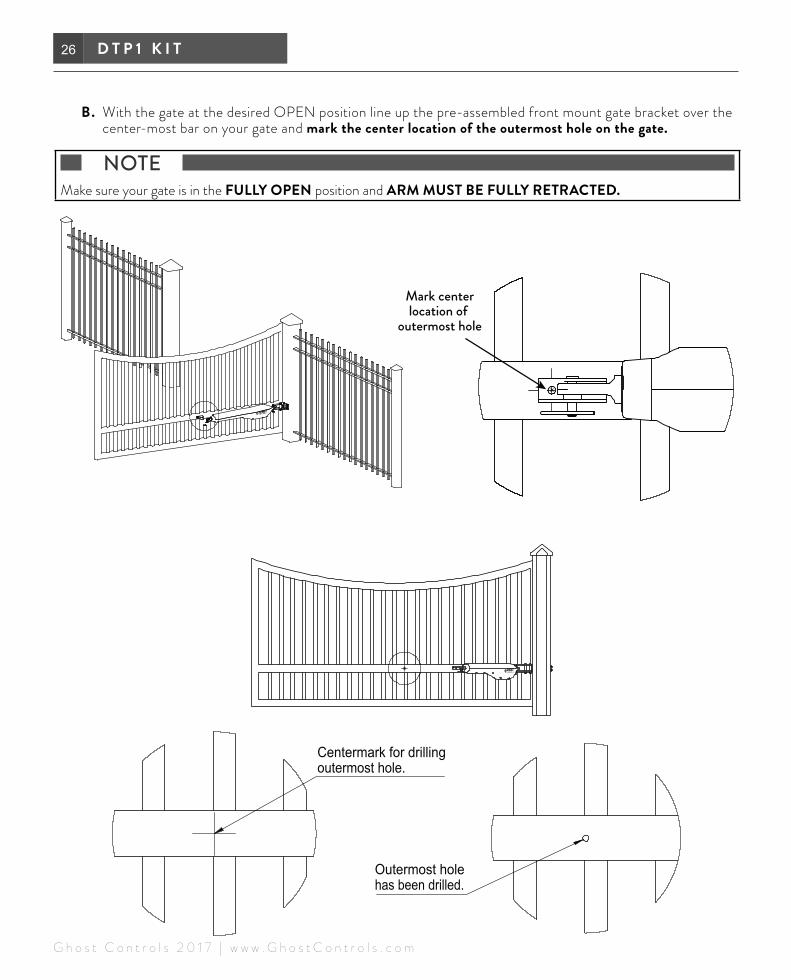
B. With the gate at the desired OPEN position line up the pre-assembled front mount gate bracket over the center-most bar on your gate and mark the center location of the outermost hole on the gate.
NOTE Make sure your gate is in the FULLY OPEN position and ARM MUST BE FULLY RETRACTED.
Mark centerlocation of
outermost hole

27P U L L - T O - O P E N
G h o s t C o n t r o l s 2 0 1 7 | w w w . G h o s t C o n t r o l s . c o m
C. Install the gate and estate brackets on the gate by aligning the outermost hole of both brackets and inserting (1) M8 x 65mm flat washer, and (1) M8 nylon locknut thru both the estate and gate brack-ets, as show below. Tighten to secure the brackets to the gate. MAKE SURE GATE IS STILL IN OPEN POSITION (arm must be fully retracted)
Estate Bracket installon backside of gate
Gate Bracket
D. Disconnect operator from gate bracket and swing away from the gate.
Remove the clevis pin,hair pin, and front spacer.

28 D T P 1 K I T
G h o s t C o n t r o l s 2 0 1 7 | w w w . G h o s t C o n t r o l s . c o m
E. Assemble clevis pin, front spacer and hair pin to operator to prevent loss.
F. Now you can mark and drill the inner most hole on the gate bracket, shown below.
G. Align the innermost holes of both the estate and the gate brackets and insert (1) M8 x 65mm flat washer, and (1) M8 nylon locknut thru both holes and tighten to secure the brackets to the gate. YOUR GATE BRACKET AND ESTATE BRACKET SHOULD NOW BE ATTACHED AND SECURED TO THE GATE.
29P U L L - T O - O P E N
G h o s t C o n t r o l s 2 0 1 7 | w w w . G h o s t C o n t r o l s . c o m
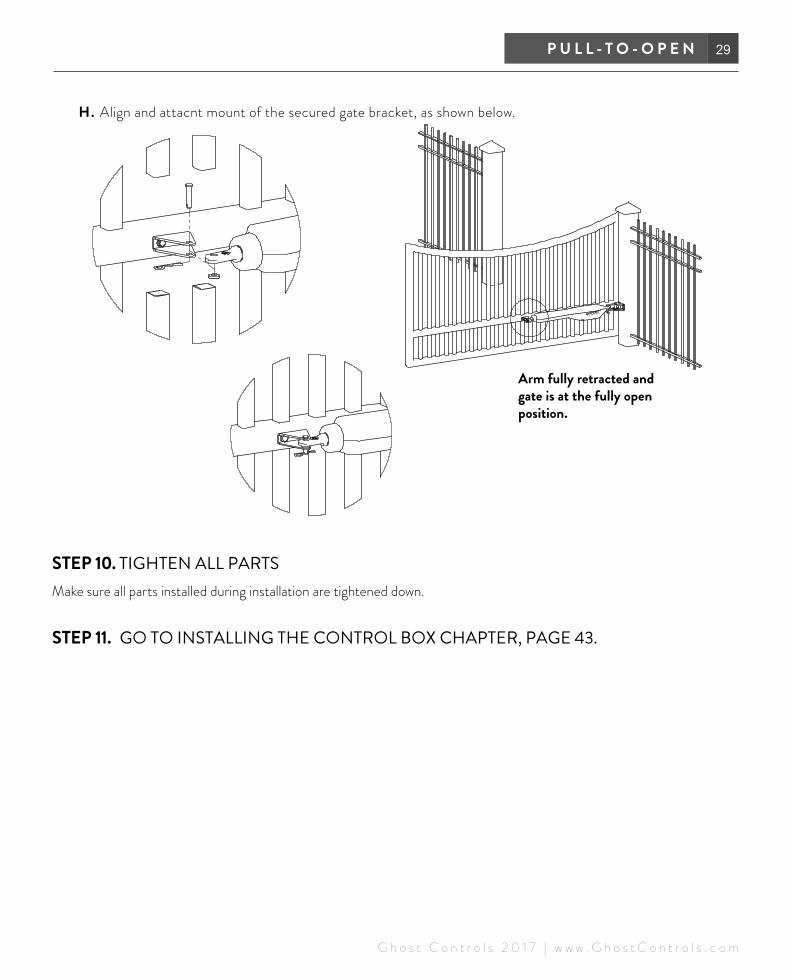
H. Align and attacnt mount of the secured gate bracket, as shown below.
STEP 10. TIGHTEN ALL PARTSMake sure all parts installed during installation are tightened down.
STEP 11. GO TO INSTALLING THE CONTROL BOX CHAPTER, PAGE 43.
Arm fully retracted and gate is at the fully open position.

30 D T P 1 K I T
G h o s t C o n t r o l s 2 0 1 7 | w w w . G h o s t C o n t r o l s . c o m

31P U S H - T O - O P E N
G h o s t C o n t r o l s 2 0 1 7 | w w w . G h o s t C o n t r o l s . c o m
PUSH-TO-OPEN: GATE SWINGS TO OPEN OUTSIDE PROPERTYThe dimensions and step-by-step instructions that follow are for mounting the GHOST CONTROLS® Gate Operator system to a standard metal tubular-style agricultural fence that swings into property. YOU WILL NEED TO MAKE SURE YOU PURCHASE THE PUSH-TO-OPEN BRACKET KIT (AXPO) BEFORE YOU START INSTALLING.For pull-to-open applications, please see Pull-To-Open Application on page “PULL-TO-OPEN: gate Swings to Open Inside Property” on page 19.STEP 1. AS STATED IN THE PLANNING SECTION, YOU SHOULD CHECK TO INSURE
YOUR GATE IS LEVEL AND PLUMB.
Make sure posts are set firmly in concrete and that the gate swings freely.
LEVEL
CONCRETE THE POSTS IN THE GROUND
INSTALL OPERATOR PUSH-TO-OPEN SYSTEMS
32 D T P 1 K I T
G h o s t C o n t r o l s 2 0 1 7 | w w w . G h o s t C o n t r o l s . c o m
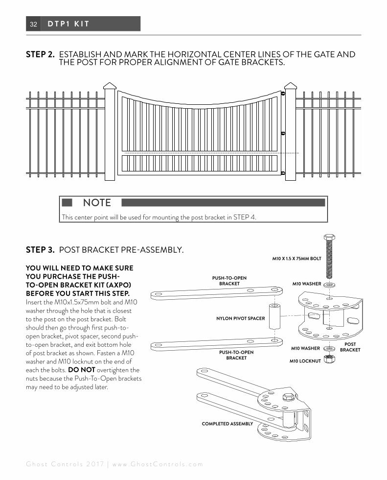
STEP 2. ESTABLISH AND MARK THE HORIZONTAL CENTER LINES OF THE GATE AND THE POST FOR PROPER ALIGNMENT OF GATE BRACKETS.
NOTE This center point will be used for mounting the post bracket in STEP 4.
STEP 3. POST BRACKET PRE-ASSEMBLY.
YOU WILL NEED TO MAKE SURE YOU PURCHASE THE PUSH-TO-OPEN BRACKET KIT (AXPO) BEFORE YOU START THIS STEP. Insert the M10x1.5x75mm bolt and M10 washer through the hole that is closest to the post on the post bracket. Bolt should then go through first push-to-open bracket, pivot spacer, second push-to-open bracket, and exit bottom hole of post bracket as shown. Fasten a M10 washer and M10 locknut on the end of each the bolts. DO NOT overtighten the nuts because the Push-To-Open brackets may need to be adjusted later.
PUSH-TO-OPEN BRACKET
PUSH-TO-OPEN BRACKET
NYLON PIVOT SPACER
COMPLETED ASSEMBLY
M10 X 1.5 X 75MM BOLT
M10 WASHER
M10 WASHER
M10 LOCKNUT
POSTBRACKET

33P U S H - T O - O P E N
G h o s t C o n t r o l s 2 0 1 7 | w w w . G h o s t C o n t r o l s . c o m
STEP 4. CLAMPING POST BRACKET TO POST.
After the post bracket is pre-assembled and the horizontal centerline has been marked on the post as referred to in Step 2 and 3, then proceed to clamp the post bracket to the marked centerline on the post.
NOTE It is recommended for many Push-To -Open applications to not center the bracket. Position the edge of the bracket along the edge of the post (closest to the gate) and check the clearances in Step 5.
Some Pull-To-Open applications may require the bracket to be positioned along the edge of post furthest from the gate to obtain clearances that will be checked in Step 5.

34 D T P 1 K I T
G h o s t C o n t r o l s 2 0 1 7 | w w w . G h o s t C o n t r o l s . c o m
STEP 5. VERIFYING GATE CLEARANCE. GATE MUST BE IN FULLY CLOSED POSITION.
NOTE Gate needs to be in the FULLY CLOSED POSITION before measuring the distance between the indicated bracket hole and the place marked on the tube in STEP 5.
Distance must begreater than 4.5"
Top View of FenceTop View of Gate
Top View of Gate
35P U S H - T O - O P E N
G h o s t C o n t r o l s 2 0 1 7 | w w w . G h o s t C o n t r o l s . c o m
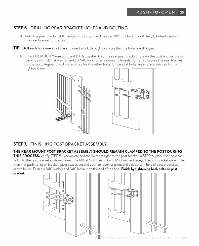
STEP 6. DRILLING REAR BRACKET HOLES AND BOLTING.
A . With the post bracket still clamped to post you will need a 3/8” drill bit and drill the (4) holes to mount the rear bracket to the post.
TIP: Drill each hole one at a time and insert a bolt through to ensure that the holes are all aligned.
B. Insert (1) M-10-175mm bolt, and (1) flat washer thru the rear post bracket hole on the post and secure on backside with (1) flat washer and (1) M10 locknut as shown and loosely tighten to secure the rear bracket to the post. Repeat this 3 more times for the other bolts. Once all 4 bolts are in place you can firmly tighten them
STEP 7. FINISHING POST BRACKET ASSEMBLY.THE REAR MOUNT POST BRACKET ASSEMBLY SHOULD REMAIN CLAMPED TO THE POST DURING THIS PROCESS. Verify STEP 5 is complete and the bolts are tight to the post bracket in STEP 6, place the secondary bolt into the post bracket as shown. Insert the M10x1.5x75mm bolt and M10 washer through the post bracket outer hole, then first push-to-open bracket, pivot spacer, second push-to-open bracket, and exit bottom hole of post bracket as shown below. Fasten a M10 washer and M10 locknut on the end of the bolt. Finish by tightening both bolts on post bracket.
36 D T P 1 K I T
G h o s t C o n t r o l s 2 0 1 7 | w w w . G h o s t C o n t r o l s . c o m
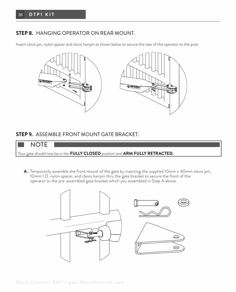
STEP 8. HANGING OPERATOR ON REAR MOUNT.
Insert clevis pin, nylon spacer and clevis hairpin as shown below to secure the rear of the operator to the post.
STEP 9. ASSEMBLE FRONT MOUNT GATE BRACKET.
NOTE Your gate should now be in the FULLY CLOSED position and ARM FULLY RETRACTED.
A . Temporarily assemble the front mount of the gate by inserting the supplied 10mm x 40mm clevis pin, 10mm I.D. nylon spacer, and clevis hairpin thru the gate bracket to secure the front of the operator to the pre-assembled gate bracket which you assembled in Step A above.

37P U S H - T O - O P E N
G h o s t C o n t r o l s 2 0 1 7 | w w w . G h o s t C o n t r o l s . c o m
NOTE ALTERNATE TUBE GATE BRACKETS FOR MOUNTING TUBULAR GATES. (NOT FOR USE WITH FLAT PANEL GATES) see below image. Tube brackets (AXTB) sold separately.

38 D T P 1 K I T
G h o s t C o n t r o l s 2 0 1 7 | w w w . G h o s t C o n t r o l s . c o m
B. With the gate in the CLOSED position line up the pre-assembled front mount gate bracket over the cen-ter-most bar on your gate and mark the center location of the outermost hole on the gate.
NOTE Make sure your gate is in the FULLY CLOSED position and ARM FULLY RETRACTED.
Mark centerlocation of
outermost hole

39P U S H - T O - O P E N
G h o s t C o n t r o l s 2 0 1 7 | w w w . G h o s t C o n t r o l s . c o m
C. Install the gate and estate brackets on the gate by aligning the outermost hole of both brackets and inserting (1) M8 x 65mm flat washer, and (1) M8 nylon locknut thru both the estate and gate brackets, as show below. Tighten to secure the brackets to the gate. MAKE SURE GATE IS STILL IN CLOSED POSITION (arm fully retracted).
D. Disconnect operator from gate bracket and swing away from the gate.
Remove the clevis pin,hair pin, and front spacer.
40 D T P 1 K I T
G h o s t C o n t r o l s 2 0 1 7 | w w w . G h o s t C o n t r o l s . c o m
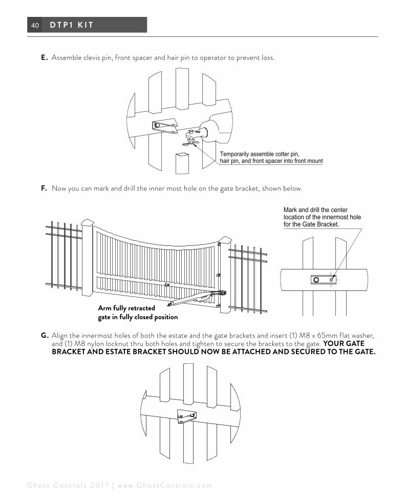
E. Assemble clevis pin, front spacer and hair pin to operator to prevent loss.
F. Now you can mark and drill the inner most hole on the gate bracket, shown below.
G. Align the innermost holes of both the estate and the gate brackets and insert (1) M8 x 65mm flat washer, and (1) M8 nylon locknut thru both holes and tighten to secure the brackets to the gate. YOUR GATE BRACKET AND ESTATE BRACKET SHOULD NOW BE ATTACHED AND SECURED TO THE GATE.
Arm fully retracted gate in fully closed position

41P U S H - T O - O P E N
G h o s t C o n t r o l s 2 0 1 7 | w w w . G h o s t C o n t r o l s . c o m
H. Align and attach the operator to the front mount of the secured gate bracket, as shown below.
STEP 10. TIGHTEN ALL PARTSMake sure all parts installed during installation are tightened down.
STEP 11. GO TO INSTALLING THE CONTROL BOX CHAPTER, PAGE 43.

42 D T P 1 K I T
G h o s t C o n t r o l s 2 0 1 7 | w w w . G h o s t C o n t r o l s . c o m

43C O N T R O L B O X
© G h o s t C o n t r o l s 2 0 1 7 | w w w . G h o s t C o n t r o l s . c o m
NOTE Mount the control box a minimum of 3 feet above the ground to keep dirt and water from damaging the control board and within 4 feet of the operator arm in order for the operator cable to reach the control box.
STEP 1. INSTALLING THE CONTROL BOXA . Pre-drill (4) holes (7/32” drill bit) in backside of control box, and thru the fencing where you will be securing
the control box to.
B. Now use the (4) supplied phillips screws to mount the control box to the fence.
STEP 2. MAKE SURE THE ON/OFF SWITCH ON BOTTOM OF CONTROL BOX IS IN THE OFF POSITION
INSTALLING CONTROL BOX INSTRUCTIONS

44 C O N T R O L B O X
© G h o s t C o n t r o l s 2 0 1 7 | w w w . G h o s t C o n t r o l s . c o m
STEP 3. ROUTING THE OPERATOR CABLE AND BATTERY HARNESS INTO THE CONTROL BOX
A . First route the battery harness cable thru the strain relief on the bottom of the control box and connect the bullet connectors (red to red, black to black) to the control board harness. See below diagram.
B. Route the operator cable thru the same strain relief into the control box. We recommend feeding the cable through PVC conduit. Follow the diagram below.
C. Connect the operator wires to the control board. See diagram above. Find the 1st operator screw terminal on control board and insert the red, black, green and white wires into the matching terminals and tighten each of the screws so that the wires do not come loose and fall out.
B

45C O N T R O L B O X
© G h o s t C o n t r o l s 2 0 1 7 | w w w . G h o s t C o n t r o l s . c o m
STEP 4. ROUTING THE AC TRANSFORMER CABLE INTO THE CONTROL BOX
A . When wiring the AC Transformer you will need to insert the AC wires in the matching terminals 2 and 3 on the 16 VAC PWR INPUT screw terminal on the main control board and tighten each screw so that the wires do not come loose and fall out. Please refer to diagram below. DO NOT HOOK UP SOLAR IF USING AC TRANSFORMER.
DO NOT PLUG IN THE AC TRANSFORMER DURING THIS STEP.
B. Connect AC Transformer to outdoor outlet. Make sure you connect AC Transformer wires to control board prior to plugging in AC Transformer into weatherproof outdoor outlet. Please refer to diagram below.

46 C O N T R O L B O X
© G h o s t C o n t r o l s 2 0 1 7 | w w w . G h o s t C o n t r o l s . c o m
46
STEP 5. ADDING A SOLAR PANEL (OPTIONAL) TO THE CONTROL BOX
When wiring a Solar Panel you will need to remove the plug in the negative solar terminal on the main control board and then connect the solar panel wires to the matching terminals 1 and 3 on the SOLAR PWR INPUT screw terminal on the control board. Please refer to diagram below. DO NOT HOOK UP AC TRANSFORMER IF USING SOLAR POWER.
STEP 6. HOOK UP YOUR BATTERY. GO TO INSTALLING THE BATTERY BOX CHAPTER, PAGE 47.
BLACK RED

47B A T T E R Y B O X
© G h o s t C o n t r o l s 2 0 1 7 | w w w . G h o s t C o n t r o l s . c o m
BATTERY BOX SHOULD BE MOUNTED NEXT TO (OR BELOW) CONTROL BOX SO THAT POWER HARNESS CAN CONNECT INTO MAIN SYSTEM CONTROL BOARD THROUGH THE STRAIN RELIEF.
GHOST CONTROLS® does not recommend splicing the battery harness wire to extend its length. Battery Box should be mounted at least three feet above ground to avoid any standing water or snow and to prevent damage from landscaping equipment such as string trimmers or lawn mowers.
The included mounting screws are designed to be installed into wood or metal posts. If you are installing onto a post or column made of material other than wood or metal, you must replace the screws (not included) with appropriate mounting screws.
INSTALLING YOUR BATTERY BOX:
STEP 1. PLAN YOUR INSTALLATION LOCATION
Battery Box Kit must be located within 4 feet of control box and mounted to a solid object such as the fence.
STEP 2. MOUNT BOX WITH MOUNTING SCREWS
A . Pre-drill (4) holes (7/32” drill bit) in backside of battery box, and thru the fencing where you will be securing the battery box to.
B. Now use the (4) supplied phillips screws to mount the control box to the fence.
CONTROL BOX BATTERY BOX
I N S TA L L I N G B AT T E R Y B OX INSTRUCTIONS

48 B A T T E R Y B O X
© G h o s t C o n t r o l s 2 0 1 7 | w w w . G h o s t C o n t r o l s . c o m
48
STEP 3: ATTACH POWER HARNESS TO SYSTEM CONTROL BOARD
A . Turn the power switch to the GHOST CONTROLS® control box to the off position before making connections.
B. Feed the power harness out of the battery box through its strain relief and up into system control box through the strain relief on the bottom of the control box. See image below.
C. Connect the two bullet connectors from the battery box harness to the bullet connectors of the control board as shown below.
Route power cable from inside of battery box through the strain-relief, then into the
control box through its strain-relief.
Once routed into the Control Box (as shown), connect the terminals of the power cable. (Batteries not shown.)

49B A T T E R Y B O X
© G h o s t C o n t r o l s 2 0 1 7 | w w w . G h o s t C o n t r o l s . c o m
STEP 4: CONNECT THE BATTERY OR BATTERIES IN THE BATTERY BOX
Make sure to check for the proper polarity of wires. One or two batteries can be connected. Red connector goes on positive battery terminal first and black connector goes on negative terminal of battery.
Connect the battery power cable terminals to the batteries in the Battery Box; an optional second battery is shown. Connect the red wire leads to the
positive (+) terminals, and connect the black wire leads to the negative (-) terminals. Place the batteries into the battery box once they are connected.
Once connected, pull slack out of the battery power cable, coil the excess wire, and place it inside of the Battery Box.
Tighten the Strain Relief Nuts of both the Control Box and the Battery Box to close the seals around the wires. DO NOT OVERTIGHTEN.

50 B A T T E R Y B O X
© G h o s t C o n t r o l s 2 0 1 7 | w w w . G h o s t C o n t r o l s . c o m
STEP 5: TURN ON MAIN SYSTEM CONTROL BOX
Turn the main system toggle power switch located at the bottom of system control box to the on position.
STEP 6: TEST THE SYSTEM
Test the system with remote, keypad, or push button.
STEP 7: LOCK THE BOX (OPTIONAL)
You can purchase an optional AX3L Operator Security Kit to lock the operator, control box, and battery box with three different padlocks that are keyed alike.

51P R E P A R I N G
G h o s t C o n t r o l s 2 0 1 7 | w w w . G h o s t C o n t r o l s . c o m
PREPARING THE GATE SYSTEM CONTROLLER PULL-TO-OPEN AND PUSH-TO-OPEN APPLICATIONS
GATE SYSTEM CONTROLLERThe gate system control board provides one convenient place to make all of your system connections and to change any settings that you desire to personalize how your automatic gate opener system operates at your home or property. This main board (shown below) is located inside of the control box of your system and will be referred to in detail through the next few sections. Because this control box may be mounted within reach of children or potential vandals, we offer and recommend an operator lock security kit (AX2L) as an accessory to safely lock this box in the closed position to prevent tampering. NOTE: BEFORE PROCEEDING MAKE SURE THE ON/OFF SWITCH ON BOTTOM OF CONTROL BOX IS IN THE OFF POSITION REFERENCE PAGE 43.
52 P R E P A R I N G
G h o s t C o n t r o l s 2 0 1 7 | w w w . G h o s t C o n t r o l s . c o m
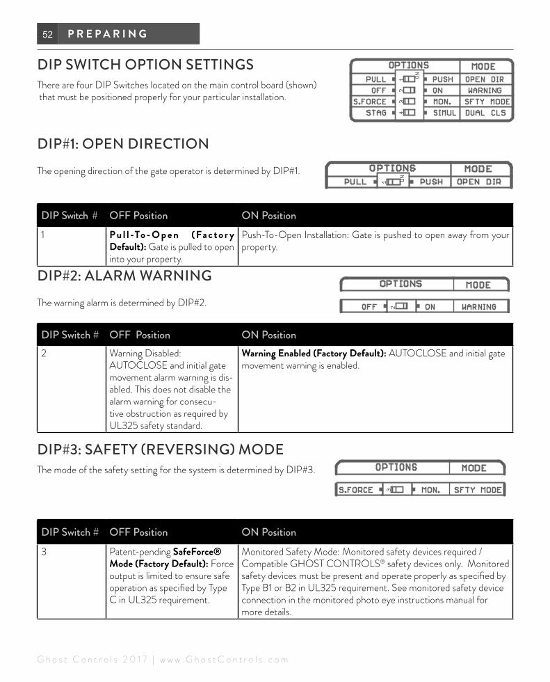
DIP SWITCH OPTION SETTINGSThere are four DIP Switches located on the main control board (shown) that must be positioned properly for your particular installation.
DIP#1: OPEN DIRECTIONThe opening direction of the gate operator is determined by DIP#1.
DIP Switch # OFF Position ON Position1 P u l l -To - O p e n (Fa c t o r y
Default): Gate is pulled to open into your property.
Push-To-Open Installation: Gate is pushed to open away from your property.
DIP#2: ALARM WARNINGThe warning alarm is determined by DIP#2.
DIP Switch # OFF Position ON Position2 Warning Disabled:
AUTOCLOSE and initial gate movement alarm warning is dis-abled. This does not disable the alarm warning for consecu-tive obstruction as required by UL325 safety standard.
Warning Enabled (Factory Default): AUTOCLOSE and initial gate movement warning is enabled.
DIP#3: SAFETY (REVERSING) MODEThe mode of the safety setting for the system is determined by DIP#3.
DIP Switch # OFF Position ON Position3 Patent-pending SafeForce®
Mode (Factory Default): Force output is limited to ensure safe operation as specified by Type C in UL325 requirement.
Monitored Safety Mode: Monitored safety devices required / Compatible GHOST CONTROLS® safety devices only. Monitored safety devices must be present and operate properly as specified by Type B1 or B2 in UL325 requirement. See monitored safety device connection in the monitored photo eye instructions manual for more details.

53P R E P A R I N G
G h o s t C o n t r o l s 2 0 1 7 | w w w . G h o s t C o n t r o l s . c o m
DIP#4: DUAL (BI-PARTING) GATE OPENING SEQUENCEThe gate opening sequence for dual gate opener systems only is determined by DIP#4. This DIP switch does not apply to single gate opener installations.
NOTE The SECOND arm will always CLOSE first before the FIRST arm.
DIP Switch # OFF Position ON Position4 Delay Open (Factory Default):
FIRST arm will open before the SECOND arm.
Simultaneous Open: Both the FIRST arm and the SECOND arm will simultaneously OPEN.
If Gate Lock is installed, the system will ignore this DIP switch setting and default to delay open on the SECOND arm.
Not to be used with ZOMBIELOCK.
RECAP OF FACTORY SETTINGS FOR DIP SWITCHESWe recommend you mark your initial settings by placing a checkmark on this chart to refer to later if needed.
DIP Switch # OFF Position ON Position
1 Factory Default: Pull-To-Open Push-To-Open
2 Warning Disabled Factory Default: Warning Enabled
3 Factory Default: SafeForce® Mode Monitored Safety Mode
4 Factory Default:
Delay Open SECOND Arm
Simultaneous Open

54 P R E P A R I N G
G h o s t C o n t r o l s 2 0 1 7 | w w w . G h o s t C o n t r o l s . c o m
PAGE LEFT BLANK

55P R O G R A M M I N G
G h o s t C o n t r o l s 2 0 1 7 | w w w . G h o s t C o n t r o l s . c o m
NOTE Only the arms’ extended limit is adjustable. The arms’ retracted position is FIXED and is NOT electronically adjustable. The retracted position is set by hardware mounting only. Please refer to the hardware installation to make sure the retracted position is properly set/installed.
Installation Type Retracted Position Extended Position Proceed ToPull-To-Open Gate at the fully OPEN
position (not electronically adjustable)
Gate at the CLOSED position (electronically adjustable)
Setting the Closed Position on page 55
Push-To-Open Gate at the CLOSED posi-tion (not electronically adjustable)
Gate at the fully OPEN position (electronically adjustable)
Setting the Open Position on page 56
SET THE CLOSED POSITION LIMIT FOR A PULL-TO-OPEN INSTALLATIONThis is the most common installation. The CLOSED limit is when the operator is fully extended and the gate is in the closed position.
1 . Verify that the control box power switch is in the ON position. Turn on if necessary.
2 . Move the gate to the desired CLOSED position using the JOG CLOSE or JOG OPEN buttons on the gate system control board. The JOG buttons on the system control board (shown) can move the gate only if pressure is maintained, releasing the button will stop the gate immediately. The JOG buttons can be used as ‘fine’ adjustment of the CLOSED limit.
3 . Once the gate is in the desired CLOSED position, press and hold the 1st SET button until the alarm sounds, then release the button. The unit is now in LEARN LIMIT mode.
4 . Press the remote to run the gate to the fully OPEN position.
PROGRAMMING THE GATE SYSTEM CONTROLLER PULL-TO-OPEN AND PUSH-TO-OPEN APPLICATIONS

56 P R O G R A M M I N G
G h o s t C o n t r o l s 2 0 1 7 | w w w . G h o s t C o n t r o l s . c o m
5 . The system alarm will beep once to indicate that the new CLOSED limit is learned and stored.
6 . Confirm the newly programmed CLOSED limit by pressing the remote and run the gate in the closing direction. The gate should automatically stop at the position in step 2 above. This limit is stored and remem-bered even when all of the power sources are removed.
7. Skip the next section on “Push-To-Open” and go to the “ADJUST THE FORCE SETTING” section on page 56.
SET THE OPEN POSITION LIMIT FOR A PUSH-TO-OPEN INSTALLATION1 . Verify that the control box power switch is in the ON
position. Turn on if necessary.
2 . Move the gate to the desired OPEN position using the remote or the JOG CLOSE or JOG OPEN buttons on the gate system control board. The JOG button on the system control board (shown below) can move the gates only if pressure is maintained, releasing the button will stop the gate immediately. The JOG button can be used as ‘fine’ adjustment of the OPEN limit.
3 . Press and hold the 1st SET button until the alarm sounds, then release the button. The unit is now in LEARN LIMIT mode.
4 . Press the remote to run the gate to the fully CLOSED position.
5 . The system alarm will beep once to indicate that the new OPEN limit is learned and stored.
6 . Confirm the newly programmed OPEN limit by pressing the remote and run the gate in the opening direction. The gate should automatically stop at the position set in step 2. This limit is stored and remembered even when all of the power sources are removed.
ADJUST THE FORCE SETTINGThe FORCE SETTING potentiometer controls the maximum amount of force that the operator will use to safely move the gate.
NOTE The FORCE Setting needs to be adjusted only if your gate moves slower than normal. GHOST CONTROLS® recommends for safety reasons that you set this at the lowest possible setting. SafeForce® will not allow you to adjust this higher than the UL325 standard allows.
The FORCE SETTING potentiometer operates like a volume dial on a radio. (shown below)
Turning the potentiometer in the clockwise direction increases the maximum amount of force the gate opener will use to safely move the gate. Turning the potentiometer in the counterclockwise direction decreases the amount of force the gate opener will use to safely move the gate.
NOTE Maintaining your gate over various seasons of the year is important because ambient temperature variations may cause the force required to move your gate to increase or decrease. Wind may also cause your gate to require more force to open and is the reason that GHOST CONTROLS® does not recommend solid gates to be used with these operators.

57P R O G R A M M I N G
G h o s t C o n t r o l s 2 0 1 7 | w w w . G h o s t C o n t r o l s . c o m
SETTING AUTOCLOSEMinimum AUTOCLOSE Time Period
Maximum AUTOCLOSE Time Period
5 Seconds 60 Minutes. If longer time is needed, you should enable PartyMode or Disable AUTOCLOSE.
The AUTOCLOSE TIME setting determines how long the gate will remain open each time it operates before auto-matically closing. The factory default setting is off which requires the user to push either a remote transmitter button, keypad code, or pushbutton to close the gate.
NOTE The AUTOCLOSE time period begins once the gate has reached its open limit.
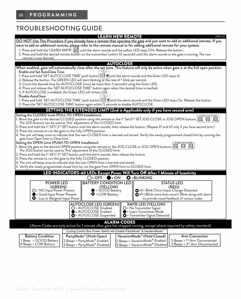
1 . Press and hold the SET AUTOCLOSE TIME button (shown below) on the Control Board until the system alarm sounds and the LED stays lit.
2 . Release the button and begin monitoring your open time on a clock or count the number of times the LED blinks (1 blink per second).
3 . When the desired AUTOCLOSE time is reached (no less than 5 seconds or more than 60 minutes), press and release the SET AUTOCLOSE TIME button.
4 . The AUTOCLOSE feature is now enabled.
CANCELLING AUTOCLOSE NOTE Canceling AUTOCLOSE can only be performed when the gate opener is idle.
Cancelling AUTOCLOSE will remove your previous duration setting and force you to pick a new duration the next time you enable AUTOCLOSE. You can use PartyMode™ to temporarily disable AUTOCLOSE and the system will retain your current AUTOCLOSE duration when PartyMode™ is disabled. Turning the control board off will not remove AUTOCLOSE because turning the system back on will automatically reengage the Auto-Close feature.
1 . Press and hold the SET AUTOCLOSE TIME button (show here) on the system control board until the alarm beeps and the LED next to the auto-close button stays lit (approximately 1 second).
2 . Release the SET AUTOCLOSE TIME button. The LED next to the autoclose button will start blinking at the rate of 1 blink per second.
3 . Within 5 seconds, press and release the SET AUTOCLOSE TIME button to disable the autoclose feature.
4 . The AUTOCLOSE is now disabled until you enable it again with a new setting.
AUTOCLOSE LED INDICATORThe AUTOCLOSE LED indicates which mode the gate system controller is currently in. Note, that this LED will turn OFF after one minute of inactivity to conserve system power.LED Solid On
LED Blinking On & Off
LED Off
AUTOCLOSE is enabled
AUTOCLOSE is enabled but tem-porarily suspended because PartyMode has been acti-vated. Disabling PartyMode will turn the LED back to a Solid On.
Assuming system has been active within the last minute, this indicates that AUTOCLOSE is disabled.
58 P R O G R A M M I N G
G h o s t C o n t r o l s 2 0 1 7 | w w w . G h o s t C o n t r o l s . c o m
TROUBLESHOOTING GUIDE

59A C C E S S O R I E S
G h o s t C o n t r o l s | w w w . G h o s t C o n t r o l s . c o m
NOTE Please refer to manufacturers manual or website for more detailed instructions on how to connect and use accessories with your gate operator.
PREPARING CONTROL BOX FOR ACCESSORY WIRINGMAKE SURE THE POWER IS TURNED OFF WHICH IS LOCATED ON THE BOTTOM OF THE CONTROL BOX BEFORE WIRING.
CONNECTING GHOST CONTROLS ZOMBIE GATE LOCK (AXZL) NOTE Please refer to manufacturers manual or website for more detailed instructions on how to connect and use accessories with your gate operator.
■ ONLY ACCEPTS patented GHOST CONTROLS® AXZL Zombie Gate Lock with feedback system.
■ Controller will automatically detect lock present and respond accordingly. ■ Lock (if present) will be pulled (unlocked) for the first few seconds while opening. If lock
is not completely pulled the gate will not open to prevent damaging to the gate and lock. ■ Lock will also be pulled (unlocked) near the closed limit position as it is closing
to ensure a smooth and "soft" operation.
CONNECTING HARDWIRED DEVICES NOTE Please refer to manufacturers manual or website for more detailed instructions on how to connect and use accessories with your gate operator.
Accepts “DRY CONTACT” input signals as control input. DRY CONTACT is passive (no power) such as a simple push button that switches from short circuit to open circuit.
CLOSE-UP VIEWOF BOTTOM OFCONTROL BOX
CONNECTING OPTIONAL ACCESSORIES CONNECTING TO CONTROL BOARD
60 A C C E S S O R I E S
G h o s t C o n t r o l s | w w w . G h o s t C o n t r o l s . c o m
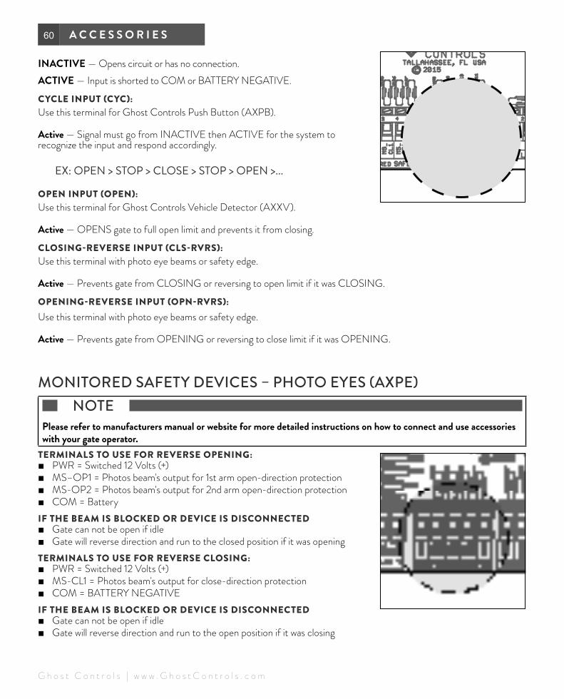
INACTIVE — Opens circuit or has no connection.ACTIVE — Input is shorted to COM or BATTERY NEGATIVE.
CYCLE INPUT (CYC):Use this terminal for Ghost Controls Push Button (AXPB).
Active — Signal must go from INACTIVE then ACTIVE for the system to recognize the input and respond accordingly.
EX: OPEN > STOP > CLOSE > STOP > OPEN >...
OPEN INPUT (OPEN):Use this terminal for Ghost Controls Vehicle Detector (AXXV).
Active — OPENS gate to full open limit and prevents it from closing.
CLOSING-REVERSE INPUT (CLS-RVRS):Use this terminal with photo eye beams or safety edge.
Active — Prevents gate from CLOSING or reversing to open limit if it was CLOSING.
OPENING-REVERSE INPUT (OPN-RVRS): Use this terminal with photo eye beams or safety edge.
Active — Prevents gate from OPENING or reversing to close limit if it was OPENING.
MONITORED SAFETY DEVICES – PHOTO EYES (AXPE) NOTE Please refer to manufacturers manual or website for more detailed instructions on how to connect and use accessories with your gate operator.
TERMINALS TO USE FOR REVERSE OPENING: ■ PWR = Switched 12 Volts (+) ■ MS–OP1 = Photos beam's output for 1st arm open-direction protection ■ MS-OP2 = Photos beam's output for 2nd arm open-direction protection ■ COM = Battery
IF THE BEAM IS BLOCKED OR DEVICE IS DISCONNECTED ■ Gate can not be open if idle ■ Gate will reverse direction and run to the closed position if it was opening
TERMINALS TO USE FOR REVERSE CLOSING: ■ PWR = Switched 12 Volts (+) ■ MS-CL1 = Photos beam's output for close-direction protection ■ COM = BATTERY NEGATIVE
IF THE BEAM IS BLOCKED OR DEVICE IS DISCONNECTED ■ Gate can not be open if idle ■ Gate will reverse direction and run to the open position if it was closing
61M A N U A L
© G h o s t C o n t r o l s 2 0 1 7 | w w w . G h o s t C o n t r o l s . c o m
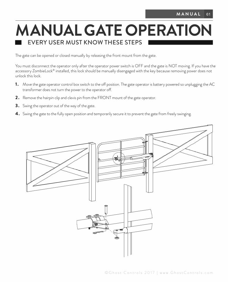
The gate can be opened or closed manually by releasing the front mount from the gate.
You must disconnect the operator only after the operator power switch is OFF and the gate is NOT moving. If you have the accessory ZombieLock® installed, this lock should be manually disengaged with the key because removing power does not unlock this lock.
1 . Move the gate operator control box switch to the off position. The gate operator is battery powered so unplugging the AC transformer does not turn the power to the operator off.
2 . Remove the hairpin clip and clevis pin from the FRONT mount of the gate operator.
3 . Swing the operator out of the way of the gate.
4 . Swing the gate to the fully open position and temporarily secure it to prevent the gate from freely swinging.
MANUAL GATE OPERATION EVERY USER MUST KNOW THESE STEPS

62 A C C E S S O R I E S
ACCESSORIESGHOST CONTROLS® genuine Accessories are designed to provide complete control and superior convenience for you and your family with your automatic gate opener. These products are specifically engineered to easily integrate into your system and grant you access to additional capabilities and control of your gate opener. All of these accessories are available from your local dealer and are backed by the same reliable warranty that your gate operator is designed to meet.
PREMIUM REMOTE TRANSMITTER | AXP1 The premium remote transmitter gate systems (single or dual) by providing the ability to open or close, enable or disable PartyMode®, determine gate opener system battery status, and can be quickly added as a new remote to an existing system. CR2032 Battery Included.
STANDARD REMOTE TRANSMITTER | AXS1The standard remote transmitter will control up to two separate GHOST CONTROLS® gate systems (single or dual) and it can be learned as a new remote to an existing system. CR2032 Battery Included.
WIRELESS KEYPAD | AXWKThe GHOST CONTROLS® Premium Wireless Keypad is the superior gateway to your gate opener system and provides unprecedented control and capabilities. This outdoor keypad is more than just an access point for visitors to your home or property who do not have a remote transmitter because it also provides the ability for you to activate or deactivate additional features for your keypad such as VACATIONMODE™.
ZOMBIELOCK® | AXZLThe patent pending ZOMBIELOCK® will provide your home with the latest in automatic gate lock technology with advanced feedback to your GHOST CONTROLS® gate controller.
LOCKING CLEVIS PIN | AXLCThe GHOST CONTROLS® Locking Clevis Pin allows you to easily secure the gate operator arm to the mounting brackets with a padlock by replacing the Clevis pin included in the gate opener kit.
WIRED VEHICLE SENSOR | AXXVThe GHOST CONTROLS® Vehicle Sensor is the easiest way to trigger your gate to open when a vehicle is trying to exit your property. This sensor is buried beneath the ground surface next to your driveway and connects into your gate controller box. 55’ cable included (cannot be spliced)
PREMIUM 10 WATT MONOCRYSTALLINE SOLAR PANEL | AXDP The monocrystalline 10W solar panels are a great solution for anyone who is installing a gate operator system in a remote location that does not have easy access to 120V AC power or for those who do not want to be “on the grid”.
12 VOLT , 7 AMP HOUR GEL-CELL BATTERY | AXBT
Batteries provide the primary power to the gate opener system and are installed within the larger gate control box when auto/marine batteries are not used.
PHOTO EYES | AXPEAdjustable photo eyes for your outdoor environment. We offer monitored and non-monitored versions.
PUSH-TO-OPEN GATE BRACKET KIT | AXPOThe Push-To-Open Bracket is required for any gate opener system that is installed when the installation causes the gates to swing out from the property. Most gates are installed with the swing action into the property and do not require these brackets.

63W A R R A N T Y
NOTE If your unable to access the internet please fill out the warranty form below and mail in to us at Ghost Controls 1572 Capital Circle NW, Tallahassee, FL 32303
First Name: _________________________________________ Last Name:__________________________________
Street: __________________________________________________________ Apt. #: __________________________
City : _________________________________________ State: _________________________ Zip: ________________
Phone Number: __________________________________ Email Address: __________________________________
Items and Date Purchased: *PLEASE INCLUDE COPY OF RECEIPT. DTP1
DEP2
Where did you buy your gate opener system?
Type of gate you are using?
Chain link Ornamental Tube Vinyl
Approximate Gate Weight: ___________________ pounds per leaf
Approximate Gate Length: ___________________ feet per leaf
Type of Application: Farm Home Business
Item Serial Number: __________________________________Item Serial Number: _______________________
Did you purchase any accessories? (Please list below)
WARRANTY REGISTER ONLINE WWW.GHOSTCONTROLS.COM/REGISTER