Embed Size (px)
Citation preview
GARAGE DOOR OPENER SYSTEMS
108095 -0001
11 /07/ 9 1
INSTALLATION INSTRUCTIONS AND OWNERS MANUAL
READ THESE INSTRUCTIONS CAREFULLY BEFORE INSTALLING OR USING THIS OPENER.
After installation is completed, place instructions in close
proximity to garage door.
All-American Craftsmanship
Mode in U.S.A.
9111071330 Page 1

TABLE OF CONTENTS
GENERAL INSTALLATION NOTES PAGE
ASSEMBLY DRAWING ...• . PAGE
INSTALLATION INSTRUCTIONS PAGE
WIRING INFORMATION .. . PAGE
OPERATION & ADJUSTMENT PAGE
OWNERS INFORMATION PAGE
GENERAL INFORMATION PAGE
TROUBLE SHOOTING GUIDE . PAGE
POWER UNIT ASSEMBLY PAGE
WIRING SCHEMATIC PAGE
PARTS LIST PAGE
WARRANTY PAGE
READ T HROUG H MANUAL BEFORE BEGINNING ASSEMBLY.
TOOLS NEEDED
3
4
5-8
9
10
11
11 -12
13
14
15
15
16
HOW TO USE TH IS BOOK
1. Use tools indicated by si lhouettes at top of
instruction.
2. Perform the instruction according to the words
and illustration.
3. Put a check in the box after completion of in
struction .
4. Proceed to next step.
SD ~ 7/ 16 SECURE HE ADE R BRACKET TO HEADER.
HE ADER BRACKET
HE ADER
I-leader Bracket
CENTERLINE OF DOOR
1 / 4 x 1-3/4 LAG SCREW
EXAMPLE
7/16 WRENCH
YOU W ILL NEED T HE FOLLOWI NG TOOLS SHOWN BELOW TO ASSEMBLE AND INSTALL THIS OPENER.
ELECTRIC DRILL
5/32 BIT 1/4 BIT 1/8 BIT (METAL DOORS)
A/llC:llllEllllllII•• CARPENTER LEVEL
A STEPLADDER 6'-0"
·'-----'~ HACK SAW
Page 2
NEEDLE NOSE PLIERS
, ),
~ 0
ac::::::
END WRENC H • TAPE MEASURE 7/16 & 9/16
• STRAIGHT EDGE
SLOTTED SCREWDRIVER • PENCIL
• POCKET KNIFE WIRE CUTTERS OR
W IRE STRIPPERS
NUTDRIVER 1/4" • BELL WIRE
PHILLIPS SCREWDRIVER
------------------------------------------------------.. GENERAL INSTALLATION NOTES
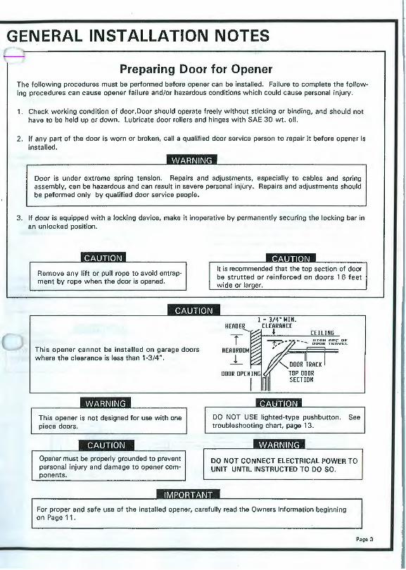
Preparing Door for Opener The following procedures must be performed before opener can be installed. Failure to complete the following procedures can cause opener failure and/or hazardous conditions which could cause personal injury.
1. Check working condition of door.Door should operate freely without sticking or binding, and should not have to be held up or down. Lubricate door rollers and hinges with SAE 30 wt. oil.
2. If any part of the door is worn or broken, call a qualified door service person to repair it before opener is installed.
Door is under extreme spring tension . Repairs and adjustments, especially to cables and spring assembly, can be hazardous and can result in severe personal injury. Repairs and adjustments should be peformed only by qualified door service people.
3. If door is equipped with a locking device, make it inoperative by permanently securing the locking bar in an unlocked position.
--•11.••• 1 11 .. ,.
Remove any lift or pull rope to avoid entrapment by rope when the door is opened.
This opener cannot be installed on garage doors where the clearance is less than 1-3/4".
This opener is not designed for use with one piece doors .
Opener must be properly grounded to prevent personal injury and damage to opener components.
It is recommended that the top section of door be strutted or reinforced on doors 16 feet wide or larger.
HEAD El._
T HEADROOM
j_
1 - 3/4" MIN . CLEARANCE
~ CEILING llIGll ORC OF DOOR TROVEL
DO NOT USE lighted-type pushbutton. See troubleshooting chart, page 13.
DO NOT CONNECT ELECTRICAL POWER TO UNIT UNTIL INSTRUCTED TO DO SO.
IMPORTANT
For proper and safe use of the installed opener, carefully read the Owners Information beginning on Page 11.
Page 3
I
Page 4
ASSEMBLY DRAWING
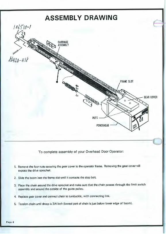
To complete assembly of your Overhead Door Operator:
1. Remove the four nuts securing the gear cover to the operator frame . Removing the gear cover wll expose the drive sprocket.
2. Slide the boom into the frame slot until it contacts the stop bolt.
3. Place the chain around the drive sprocket and make sure that the chain passes through the limit switch assembly and around the outside of the guide pulley.
4. Replace gear cover and connect chain to turnbuckle, with connecting link.
5. Tension chain until droop is 3/4 inch (lowest part of chain is just below lower edge of boom) .

INSTALLATION
1. D Measure width of door to determine center. Mark cen-
tar line on door and header.
2 X 6 WOOO BLOCK
ATIACHM£MI FDR ODDR BRACKET -ODORS WllHOUI CfNIER Sill[
If header does not have suitable woodwork where header bracket will be
installed, then such will have to be made. It is suggested that a wood
2"x6" be secured to nearby woodwork.
If door does not have a center stile or suitable material for attaching door
bracket then door must be reinforced with wood or steel at this mounting
t t. This reinforcing member must attach to both top and bottom rail
3/4" minimum headroom required above high arc of door.
3. D Position header bracket on center line and mark mounting hole
locations on center line.
HEADER
Drill 5/32" diameter holes at marked locations.
2. D 4 ii
Raise door until top section reaches it highest arc of travel. Mark header
on center line at point where level touches header.
Mark horizontal center line of header bracket 1-5/8" minimum to 3-1/4"
maximum above high arch of door travel. Use lowest figure permitted
by door counterbalance.
CARPENTERS LEVEL
HIGH ARC DF DOOR TRAVEL
IT IS RECOMMENDED THAT OPENER BE MOUNTED A MINIMUM OF 7 FEET ABOVE FLOOR
4. D ,....., 7/16
Secure header bracket to header.
~ 1/4" x 1-3/4"
LAG SCREW
114" x 1- 3/4" LAG SCREW
Page 5

5. D A 7. D
Rest header end of boom on top edge of top door section (extension
spring door) or on torsion spring (torsion spring door) and powerhead
Manually raise door to a fully opened position . If necessary, use spacers
between ladder and opener to obtain clearance between.door and opener
boom.
HIGH ARC OF OOOR BOOM
I
6. D Attach header pulley assembly to header bracket.
Carriage must be positioned near powerhead prevent interference between door and carriage.
8. D Position opener so that the boom is aligned (left and right) with the center
of the door. Then attach rear of opener to ceiling joists as illust rated in step
9. (See Notes).
e:o~,1""
~ CLEVIS PIN
•mlJl:m
In order to obtain best performance it is important that the opener be installed as close to the door as possible . If the distance between the high arc of the door and the opener boom is one inch or less then the opener may be installed in a level position. If the distance between the high arc of the door is in excess of one inch, the rear of the opener should be lowered so that the distance between the opener boom and the door (in a fully opened position) is approximately 1 /2 to 1 inch. If necessary, relocate the header bracket to maintain clearance at high arc of door.
9. D ... r __ ('\ r .,.._., 7116
1.
2.
3.
4.
5.
6.
7.
Pa e 6
Shown are examples of various installation configurations. Determine the configuration which best suits your requirements.
If necessary, span ceiling joists with wood 2x4's sufficient enough to support opener.
Hold ceiling mounting angle in mounting posi tion. Using holes in angle as a guide, drill 3/16" diameter pilot holes in cei ling joists or 2x4 framing.
Using 1/4"x1-3/4" l ag scre ws, secure ceiling mounting angle to ceiling joi sts or 2x4 framing.
Notch opener end of vertical angles (Detail A).
Using 1/4"-20x1/2" hex head bolts and lock nuts, secure angle brackets to opener.
Usi ng 1/4"-20x1/2 " hex head bolts and lock nuts, secure vertical mounting to ceiling ,a ngle. Vertical arigle s may be bent at notch~)· necessary (D etai l B) .
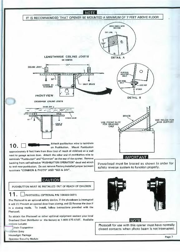
IT IS RECOMMENDED THAT OPENER BE MOUNTED A MINIMUM OF 7 FEET ABOVE FLOOR
10. D
LENGTHWISE CEILING JOISTS ON CENTER
CEILING JOI ST
.-
30'
LENGHf AS REQUIRED
FRONT VIEW
CROSSWISE CEILING JOISTS
••••--• Attac h pushbutton wire to terminals on Pushbutton. Mount Pushbutton
approximately 6 f eet from from floor (out of reach of children) on a w all
next to garage access door. Attach the other end of pushbutton wire to
HOlCll ANGEL WITH 11nct:snw
·~ " I "
DETAIL A
USE FRONT SLOT FOR BRACING
ONLY
0
DETAIL B
0
USE HOLES FOR MAIN SUPPORT
terminals "Pushbutton" and "Common" on the rear of the opener. Remove .----------- IMPORTANT backing from self-adhesive " PUSHBUTTON OPERATION" decal and attach
to wall nea r pushbutton. Do not remove Factory install ed jumper between
terminals "COMM ON & PHOTO" AND "SEC & 24V".
PUSHBUTTON MUST BE INSTALLED OUT OF REACH OF CHILDREN
11 . D PHOTOCELL (OPTIONAL P/N 108303-0001)
The Photocell is an optional safety device, if the photobeam is interrupted
it will (1) Prevent an opened door from closing, and (2) Reverse the door if
in a closing mode. To install, follow instructions provided with the
Photocell.
To obtain the Photoc ell or other optional equipment contact your local
Overhead Door Distributor or the factory at 1-800-275-6187. Available
not ions include:
~:hain Transmitter
. • eyl ess Entry
Houselight Package
Operator Security Modulo
Powerhead must be braced as shown in order for safety reverse system to function properly.
Photocell for use with this opener must have normally closed contacts when photo beam is not interrupted .
Page 7

12. ,.., .. _ .. 0"')1 7/16
Install door bracket on centerline of door as shown in step 13. The pivot hole in door
bracket should be in line, as close as possible, with the top ro llers of the door.
13.
If door strut interfers with mounting of door bracket, move bracket below strut. Do not cut or modify door strut.
The illustrations below depict installation of door bracket, p/n 105375-0001, on 3 types of doors. Install bracket in the appropriate manner according
to door type.
14. D
WOOD DOORS
C~•;~;._~C""'"" oldoo< •.., , Door lncke1
Top Rill . Lodr.tlult
Orlll (2) t/4" dl.,ne ler holu •hru door
Cenur tllle of relnfot cln 1
~br1cll1 1
114-20 X 2-t/4" curi110 bo1u
I . With door br1111ht ind
yoke1•thch•dto dr1wb1r,
••Ing 111111bly Into plac• 1111tn1tdoor.
2. Wark •ounUng hole loc1Uons.
R•hr to •ood, '"''· .,
flbergl111doordet1ll11bovt .
3. OrlU1pproprl1h1lu
•ountl1111 ho1•• ·
.. Alhchdoorbr11ck•t
to dooru1lng 11pproprl11h
h1rdw11r•.
STEEL DOORS
..... ll'l · l2 x 11•·
Self·e•lrudin11crew
STEP l
OoorBrack•t
C•nhr Sllt1
STEP 3
Attach yoke pieces to door bracket with 3/8" bolt and locknut. Tighten
locknut but do not compress yoke against door bracket - - - yoke must move
freely.
15. D Rout e pull cord through manual release lever and adjust so that release handle
is approximately 6 feet from floor. Pull release Handle and position carriage
approximately 12" from front wall .
16. D Attach door arm to carriage with clevis and hitch pins. Make sure door ls
fully closed and attach door arm to yokes with two 1 /4" bolts and nuts. Select
holes in the arm and yokes that will allow carriage to remain in the approximate
position called for in step 15.
TOP RAI L
17. D l/B - 16lOUMUJ ANO BOLT
Remove protective bracket from Emergency Release Decal end install on door
near Door Bracket .
18. D Install a 60-watt (MAX) Light Bulb.
Page 8
FIBERGLASS DOORS C on1orlln•
"'~~~!.:;:~. .. ···: . ;:\~::·:: ....... , hol•• in S•il• ..._..J HrlWI
Centu ulle • rcin(orcln1 Pl•n l>ucku
l>uckel •t•lnu rl•OI
...... ~ Cu1orf11b11orit bnckulnolde
ll':S · l2 X )/(• • .. uuded eh1nn•I s.u .•• 1.udin11enw
STEP 2
-Door Bracht
STEP 4
DoorBnckat
C1nhr Stil•
APPROX. tr
TOP DOOR SECTION
CENTER SlllE
~NUAl / RELCASE
.,,,,,.,- HANDLE
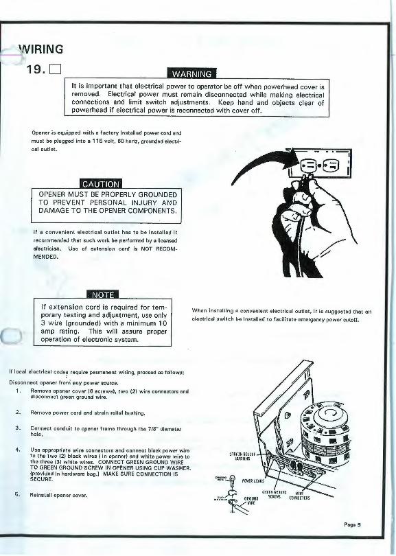
It is important that electrical power to operator be off when powerhead cover is removed. Electrical power must remain disconnected while making electrical connections and limit switch adjustments. Keep hand and objects clear of powerhead if electrical power is reconnected with cover off.
Opener is equipped w ith a factory instal led power cord and
must be plugged into a 115 vol t , 60 hertz, grounded electri
cal outlet.
OPENER MUST BE PROPERLY GROUNDED TO PREVENT PERSONAL INJURY AND DAMAGE TO THE OPENER COMPONENTS.
If a convenient elect ric al outlet has to be installed it
recommended that suc h work be performed by a li censed
electrician. Use of extension cord is NOT RECOM
MENDED.
. .. ., .•.. ._
If extension cord is required for tem· porary testing and adjustment, use only 3 wire {grounded) with a minimum 10 amp rating. This will assure proper operation of electronic system.
When instal ling a convenient elect ri cal outlet, it is suggested that an
elect ri cal switch be install ed to facilitate emergency power cutoff.
If local electri cal code7 require permanent wiring, proceed as follows:
Disconnect opener from any power source.
1. Remove opener cover (6 screws), two (2) wire connectors and disconnect green ground wire.
2. Remove power cord and strain reli ef bushing.
3. Connect conduit to opener frame through the 7/8" diameter hole.
4. Use appropriate wire connectors and co nnect black power wire to the two (2) black wires (in opener) and white power wire to the three 131 w hi te wires. CONNECT GREEN GROUND WIRE TO GREEN GROUND SCREW IN OPENER USING CUP WASHER. (provided in hardware bag.I MAKE SURE CONNECTION IS SECURE.
5. Reinstall opener cover.
~z .Pf:,.~:OUHO
,{,~IRE
Page 9
OPERATION AND ADJUSTMENTS
20. D Plug opener power cord into elect ri cal outlet , using wall button run
opener and allow chain cylinder to engage the opener carriage. NOTE:
The release lever must be in a horizontal position in orde r to obtain
engagement.
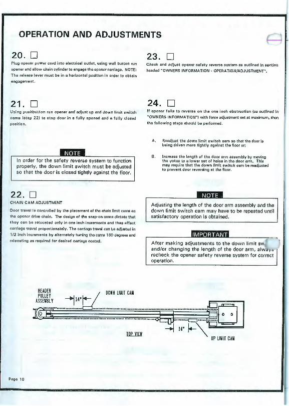
21. D Using pu shbutton run opener and adjust up and down limit switch
cams (st ep 22) to stop doo r in a fully opened and a fully closed
pos iti on.
In order for the safety reverse system to function properly, the down limit switch must be adjusted so that the door is closed tightly against the floor .
22. D CHAIN CAM ADJUSTMENT
Door travel is controll ed by the placement of the chain limit cams on
the opener drive chain . The design of the snap·o n cams dictate that
they can be relocat ed only in one inch inc reme nts and thus affect
carriage travel proportionately. The carri age travel can be adjusted in
1 /2 inch increments by alternately turning the cams 180 degrees and
re locating as required for des ired ca rri age control.
23. D Ch eck and adjust opener s afety reverse system as outlined in section
headed "OWNERS INFORMATION - OPERATION/ADJUSTMENT".
24. D If opener fail s to reve rse on th e one inc h obst ruction (as outlined in
"OWNERS INFORMATION" ) with force adjustment set et maximum, then
the following steps should be performed.
A. Readjust the down li mit switch cam so that the door is being driven more tightly agains t the fl oor or;
B. Increase the length of the door a rm assembly by moving the yokes to a lowe r set of holes in the door arm. This may require tha t the down limit switc h cam be readjusted to prevent door reversing at the fl oor.
Adjusting the length of the door arm assembly and the down limit switch cam may have to be repeated until satisfactory operation is obtained .
After making adjustments to the down limit sv( and/or changing the length of the door arm, alwa'y~ recheck the opener safety reverse system for correct operation.
HEADER i.-- I DOWN LIMIT CAM
;: ........ :t:.br .............................................................................. §1.:1 ~ ..................................................................... :tiJ.> ......... R ... ~U
~ 14' i.- '\========:t Illl'_jJ£j UP LIMIT CAM
Page 10
OWNERS INFORMATION
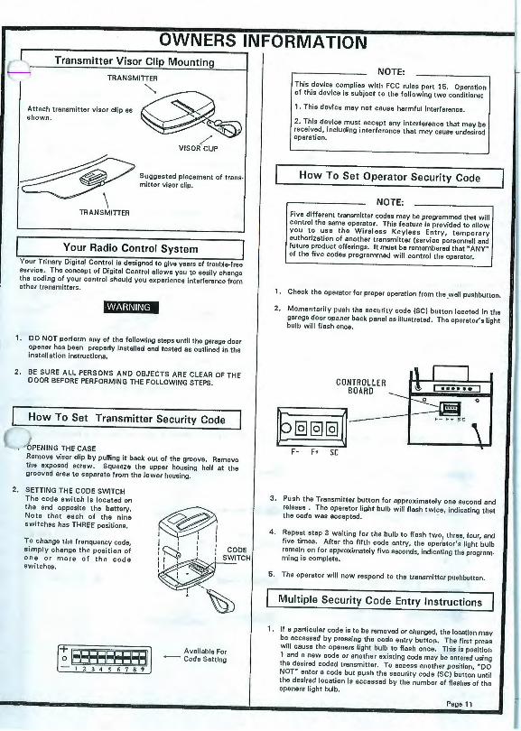
8 Transmitte~R~~::~~~p Mounting
Attach transmitter visor clip as ~ shown. ~
/ VISOR CLIP
~ Suggested placement of transmitter visor clip .
\ TRANSMITIER
I Your Radio Control System I Your Tri nary DigitaJ Control is designed to give years of trouble-free service. The concept of Digital Control allows you to easily change the coding of your control should you experience interference from other transmitters.
1. DO NOT perform any of the following steps until the garage door opener has been properly installed and tested as outlined in the installation instructions.
2. BE SURE ALL PERSONS AND OBJECTS ARE CLEAR OF THE DOOR BEFORE PERFORMING THE FOLLOWING STEPS.
How To Set Transmitter Security Code
c OPENING THE CASE Remove visor clip by pulling it back out of the groove. Remove the exposed screw. Squeeze the upper housing half at the g rooved area to separate from the lower housing.
2. SETTING THE CODE SWITCH The code switch is located on the end opposite the battery. Note that each of the nine switches has THREE positions.
To change the frenquency code, si mply change the position of one o r more of the code swi tches.
i-t IR?FERPFEEI I -123456789
@1 I I I : '('....!_ I ' CODE
:~I • _ 1 ; SWITCH I 1 : . I .. \ •
l -~
Available For -- Code Setting
NOTE:
This device complies with FCC rules part 15. Operation of this device is subject to the following two conditions:
1. This device may not cause harmful interference.
2. This device must accept any interference that may be received, including interference that may cause undesired operation.
How To Set Operator Security Code I NOTE:
Five different transmitter codes may be programmed that wi ll control the same operator. This feature is provided to allow you to us e the Wireless Keyless Entry, temporary authoriza tion of another transmitter (service personnel) and future product offerings . It must be remembered that" ANY" of the five codes programmed will control the operator.
1. Check the operator for proper operation from the .wall pushbutton.
2. Momentarily push the secu rity code (SC) button located in the garage door opener back panel as illustrated. The operator's light bulb will flash once.
CONTROLLER BOARD
\ I I I • •• • •• I
~o
~--- F~C ~ \
F- F• SC
3 . Push the Transmitter button for approximately one second and release . The operator light bulb will flash twice, indicating that the code was accepted.
4. Repeat step 3 waiting for the bulb to flash two1 three, four, and five times . After the fifth code ent ry, the oper·ator's light bulb remain on for approximately five seconds, indicating the programming is complete.
5. The operator will now respond to the transmitter pushbutton.
I Multiple Security Code Entry Instructions I 1. If a particular code is to be removed or changed, the location may
be accessed by pressi ng the code entry button . The first press will cause the openers light bulb to fl ash once. This is position 1 and a new code or another existing code may be entered using the desired coded transmitter. To access another posi tion, "DO NOT" enter a code but push the security code (SC) button until the desired location is accessed by the number of fla shes of the openers light bulb.
Page 11

J ;
2. The following table is provided for the convenience of recording the programmed security code.
MULTIPLE SECURITY CODE ENTRY TABLE
Code Position 1 Tn nsmlt1er Identification
Code Position 2 Transmitter Identification
Code Position J Transmitter Identif ication
Code Position 4 Transmitter ldnetilication
Code Posi1ion 6 Transmitter Identification
NOTE:
Identical codes may be entered in any of the locations. This allo ws easy removal of a code with a transmitter that you wish to remain authorized.
Adjustment and Testing of the Reversing System
Th e proper adjustment and testing of the Reversing System is important for the safety of everyone who uses your door and opener. Failure to properly adjust and test may result in serious personal injury fr om a closing garage door. The System consists of an electronic device that senses motor slowdown due to increased load.
l\*14;1fllf[CI The Reversing System is a safety feature that reverses the door's travel and returns it to the fully open position if the door encounters an obstruction or resistance while closing .
less For~ ~re Force
I
Force Level mi mi r;:;i I Indicator ~ 0 ~ ~ ~
F- F• SC
The forc e level is indi cated by the small green light located next to the less force button as shown . One fl ash followed by a pause indica tes that it is set for the least force that the door will exert on an obst ruc tion . Two to seven fla shes indicate six more increased force levels. The final maximum force level di splays a continuous li ght.
Operate the door and set the level to the lowest force that guarantees proper door operation . Each push of the "F +" more or "F-" less force buttons will se t the level accordingly. Do not decrease the sensi tivity to compensate for a binding or st icking door. If the fo rce level indi cator is on continuous ly read warning below.
llllij;lfllftcl
If satis fac tory operation of the door/opener cannot be achieved by fo ll ow ing the ins tructions above, disconnect the opener from the door by pulling the emergency release rope, then check operation of the door alone . If door balance, rollers, and hinges operate smoothly, wit hout s triking or binding in the jambs, reconnect the opener and repeat the sensi tivity adjustment procedure. If door/opener operation is sti ll unsatisfactory, contact an Overhead Door Distributor.
Page 12
As a final check, piece a 1" thick board on the floor in the centf' · ~ the door. When the door strikes this board it should reverse v 2 seconds and fully open. If it does not, go to page 10, step
For your safety, it is recommended that the reversing mechanism be adjusted to perform properly. Check it every six months or call a professional door service person to check it for you . If, for any reason, the opener is not functioning properly, immediately disconnect the opener from the door (Emergency Release Operation) and do not reconnect until the problem is corrected.
If satisfactory operation of the door/opener cannot be achieved by following the instructions above, disconnect the opener from the door by pulling the Emergency Release rope, then check operation of the door alone.
OPERATION
On initial power application or after a power failure, the motor will always run first in the open direction when signaled from either the transmitter or wa ll pushbutton. Thereafter opener always res tarts in the direction opposit e its last run.
TO START OPENER:
TO PARK DOOR:
Press transmitter pushbutton or wall pushbutton 1 time .
Press transmitter pushbutton or wall pushbutton while door is opening.
GENERAL INFORMATION
1. When "Emergency" or "Manual" operation of door is required, pull rel ease cord suspended from carriage or trolley.
2. To reconnect the opener, place the manual release lever in the horizontal position and run the opener. It will automatically reconnect.
I Operate door only when fully visible and clear of all I persons and obstructions.
3. If light does not work when opener is in use, replace light bulb. Use 60 watt rough service Overhead Door bulb. To remove the lens , pus h in on s ides and remove. Replace lens by inserting retai ner tabs into their holes and pus hing lens to snap tabs into place.
4. Oil door hinges, rollers and springs once each year with 30 weight oil. Wipe off any excess oil.
5. Transmitter is equipped with a 12 volt battery. Do not substitute with any other voltage battery.
6. Opener motor is protected against burnout by an internal protector which will stop motor if door is opened and closed too many times in s uccession, or if some other overload condition exis ts . If motor stops, allow it to cool 10-15 minutes, then press wall pushbutton to resume operation.
7. It is suggested that every 6 months door be di sco nnected from opener and manually operated . Door s hould open and close freely. If door do es not operate fre ely, contact an authorized Overhead Door distributor.

Door is under extreme spring tension. Repairs and adjustments, especially to cables and spring assembly, can be hazardous and can result in severe personal injury. Repairs and adjustments should be performed ONLY BY QUALIFIED OVERHEAD DOOR DISTRIBUTORS.
8. In normal applications, lubrication of opener rotating and sliding parts in not required. Motor is permanently lubricated.
9. DO NOT lubricate boom. It is possible a film may develop inside he nylon carriage. This film may cause binding in freezing weather. to correct, spray boom. or either side of carriage, with a spray lubricant (WO 40, LIQUID WRENCH, ate.). run opener open and closed, then wipe boom clean.
TRANSMITTER SERVICE HINTS NOTE:
If you have two transmitters and one does not work it is reasonable to assume the problem is in the transmitter. However, when you have one transmitter and it does not work the problem may be in the receiver. When returning the controls to the factory for service, it is always recommended that you send the receiver and all the trrans mitters so they can be tested as a set.
JM.ti en writing to the factory for assistance or when returning a ( l for repair be sure to include the following information:
1. Radio Control Model No.
2. Number of Transmlters
3. Door opener Model No. and Manufacturers Name
4. Date Unit was Installed
5. Nature of Difficulty
If you have purchased only one transmitter and you wish to purchase a second one, specify the frequency found on the white sticker on the back of the transmitter or receiver case.
REPLACING THE BATTERY: The battery is located on the end of the transmitter. Gently pry the battery up until it separates from the clips. Replace only with Overhead Door A23 or equivalent l2 volt battery. Any other style may damage the unit and will void the warranty.
NATURE OF DIFFICULTY:
1. Short Distance -
When Battery Condition Light begins to flicker, replace battery.
2. Inoperative or Intermittent Operation -
A. Check Code Switches in transmitter.
B. When Battery Condition Light on the transmitter begins to flicker, replace battery.
C. Be sure battery connector is clean and makes good contact with battery terminals in the transmitter.
NOTE: j '"' l'l rranty on the Control will be nullified if service other than I
._f ___ 'C ified in the service hints is performed by anyone other \...... ._," "authorized personnel.
TROUBLESHOOTING GUIDE
This troubleshooting guide shows malfunction symptoms and their possible causes . Use it to help determine the cause of a problem. Disconnect power to the opener before opening th~ cover.
The microprocessor does a self test when power is connected to the opener, when the pushbutton or transmitter button is pushed and at the end of the light timing cycle. The self test shows a system problem by flashing the opener lights.
* Requires the assistance of a qualified repairman.
SYMPTOM POSSIBLE CAUSE Opener light fleshes at 1 second intervals Safety System indicating fa!Jt °'Safety for 7 seconds. Wirino open.
Jumper missing between terminals Common & Photo. Photocell inoperable or misaligned.
Opener light flashes at 1·1/2 second Short in wall pushbutton, lighted intervals for 6 flashes. pushbutton or pushbutton circuit.
Opener inoperative from transmitter Of •Both limit switches are on !Door at one pushbutton when pressed but Opener and the other defective!. light flashes at 1 /2 second intervals k" 16 Defective opener wiring. flashes.
Door wi11 not open using radio°' pushbutton when pressed.
Door will not open using radio but will with pushbutton.
Door starts down, runs 1 second ard
Door runs down, hits floor and reve1ses within 112 second.
Door slarts down, runs longer than 1 second, then reverses.
Door raises, carriage hils powerhead.
Door runs up, won't run down.
Short in wall pushbutton, lighted pushbullon or pushbutton circuit.
Defective transmitter, check bauery in transmitter. •Detective radio receiver.
•Reversing Syslem indicating fa!Jt Of
Safety Wiring open.
Improper adjustment of down limit switch. •Defective limit switch. •Defective circUt board.
Obstruction in doorway or roller pathway. Herd operating or defective door. Sensitivity force leve l is set too light.
Improper adjus1ment of up limit switch. •Limit switchdefec1ive. •circui1 board defective.
•Down limit swilch or circuilry open. •Circuit board defective.
Door runs down, won't run up. •Up limit switch or circuitly open. •circuit board defec1ive.
Door runs down, hits obstruction, does not •Circuit Board defective. reve1se immediately, but reverses in 30 seconds.
Motor runs, door will not open. Broken chain, d1ive sprocket or drive gear.
Door drives into floor and does not stop •Qefeclive circLit bo81d. running un1il thermal shutdown.
Door drives inlo powerhewd and does not •Defective circuit boa1d, stop running until thermal shutdown.
Door starts up, runs longer lhan 1 second, •obstruction in doorway or roller pathway. and then stops. Haid operating or defective door.
Sensitivity force level is set too light.
Page 13
Page 14
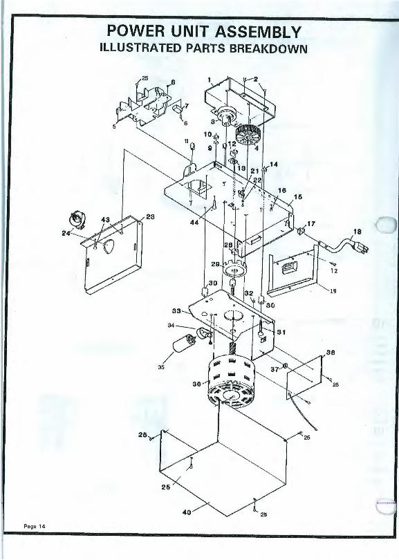
POWER UNIT ASS EMBLY ILLUSTRATED PARTS BREAKDOWN
40 25
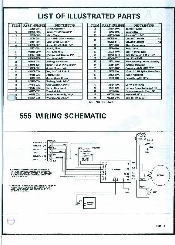
LIST OF ILLUSTRATED PARTS TTRM l>A llT N U M ~" ni<~ o .,, ~ O N ITEM l>A llT NUMBEF
I I 07519-0001 Cover Gear/Idler 23 107514-0001 2 086575-0606 Screw THDF #8-32x3/8" 24 107593-0001 3 108380-0003 Idler Chain 2S 607558-1006
26 080839-4631 080839-S Ill
4 104086-0001 Gear Main Drive Assemblv
s I 06484-0001 Limit Switch Assemblv 6 080288-0812 Screw RHMS #440 x 5/8" 28 107591-0001 7 106505-0001 Switch Limit 29 I 07384-0001 8 086480-0840 Nut Kena #4-40 30 107776-0003 9 080324-0000 Washer Lock External 114" 31 08642(}-0310
10 086480-1620 Nut Koos 1/4-20 32 086480-1232 II 086168-0003 Busbin•. Snao-Nvlon 33 I 07515-0002 12 607558-1004 Screw Tao Sit W #6-32 x 3/8" 34 I 07854-0001 13 108338-0001 Sensor Board Ontic 35 107871-0002 14 601108-0006 Nut Hex Lock #10-24 36 108379-0001 IS I 07516-0002 Frame Main 37 I 07526-0001
16 107442-0002 Screw Green Ground 38 1080'J8-0001 17 076877-0016 Bushin2. Strain Relief 18 107443-0001 Cord Assemblv. Power 40 108454-0001 19 107612-0002 Cover Coos Board 41 I 08099-0001 20 107530-0001 Terminal Strio 42 I 08096-0001
.-..1 106453-0001 Protector Assemblv. Sur2e 43 080208-1308 l t 080324-0006 Washer Lock Ext. 114" 44 080105-0406
'-J NS - NOT SHOWN
/
555 WIRING SCHEMATIC
PUSHBUTTON A
COMMON (B
PHOTOCB.l le LIGHT
SECURITY * ~E
VlO
VlOMti
24VOC LF ~,_t;~=~-ttt_J
• EXTERNAL JUMPER REC'D BETWEEN PHOTOCELL !Cl&. COMMON (B) l.M-IEN TI-I E PHOTOCELL IS NOT USED. JUMPER BETWEEN PHOTOCB.L !Cl &. COMMON !Bl MUST BE REMOVED w-IEN THAT OPTION IS SELECTED.
•• EXTERNAL JUMPER IS REC'D BETWEEN SECURITY IE) ANO 24V DC IF! Vv\-tEN SECURITY OPTION IS NOT USED. JUMPER MUST BE REMOVED Vv\-tEN THAT OPTION IS SB.ECTED.
« 11J1 '--------+-< 10 ~-------0--«9
~--------+-« • '-+-----------~7
'--4<-<------------4'.. <6
1~1------------+< 4 '---1--1-----------....,3
'--1------- -----+< 2 '------------+-< •
SENSOR BOARD
ACBBOARD
J2 3
ni<w 'll ~ ON
Bndolate Lamn Lamoholder Screw #6-32 x 3/8 • CHAIN7'BOOM NS CHAIN 8' BOOM NS Rin11. Comore11ion Rotor Ontic
Soaccr Motor Plate Bolt Carria•e #10-24 x 1-114" Nut Koos #8-32 Plate Auemblv. Motor Mountin• Retainer C101citor
Canacitor 64-77 MFD 220V Motor 112 HP Soline Shaft 6 Pole Plastic-Grommet
Controller ACB llSV
Cover Powcrhcad
HarncH Asacmblv. Control NS
Hamcsa Aasemblv. Power NS
Screw HH #10 x 112" Bolt HH 1/4-20 x 3/4"
~ GND .
Page 15

LIMITED WARRANTY Tho authorized distributor of Overheed Door Corporation products v.tlose name appears below ("Seller1 warrants this product to be free from defects in materiel and v.orkmenship under nonnel use end service. This 'Mtrranty extends only to the original consumer ("Buyer").
During tho followng periods after tho sale, Soller shell furnish goods and services indicated to repair or replace any portion of tho system determined be Soller to be defective:
1 Year All perts and labor (including installation if tho system was installed by Soller.
5 Veers Motor only.
The foregoing represents Seller's sole obligation under this warranty, end is conditioned upon Buyer giving notice to Seller Wthin the respective warranty period. Proof of purchase is re· quired.
If Seller concludes that repair or replacement is necessary, Seller Wll commence work Wthin a reasonable time after the decision to repair or replace is made.
This warranty does not apply if the system hes been ~ltered or repaired by any person not authorized by the Seller, or hes been subject to misuse, neglect or accident.
SELLER ASSUMES NO LIABILITY FOR INCIDENTAL OR CONSEQUENTIAL DAMAGES, WARRANTIES IMPLIED BY LAW ARE LIMITED IN DURATION TO ONE YEAR FROM THE DATE OF SALE.
This warranty gives you specific legal rights, and you may have other rights v.tiich very from state to state. Some states do not allow limitations on how long an implied 'Mtrrantylests, end some states do not allow the exclusion or limitation of incidental or consequential damages, so the above limitations or exclusions may not apply to you.
PARTS AND SERVICE
Page 16
For parts and service, contact the nearest Distributor. When ordering parts, please specify:
MODEL NUMBER
PART NUMBER
PART DESCRIPTION
Repairs to transmitter and receiver should be performed by a qualified repairman . See Radio Control Instructions.