Embed Size (px)
Citation preview

OL-30167-01
DTACS 3.0
Installation and Upgrade Guide for the Explorer Controller


Please Read
Important
Read this entire guide. If this guide provides installation or operation instructions, give particular attention to all safety statements included in this guide.

Notices
Trademark Acknowledgments
Cisco and the Cisco logo are trademarks or registered trademarks of Cisco and/or its affiliates in the U.S. and other countries. To view a list of Cisco trademarks, go to this URL: www.cisco.com/go/trademarks.
Third party trademarks mentioned are the property of their respective owners.
The use of the word partner does not imply a partnership relationship between Cisco and any other company. (1110R)
Publication Disclaimer
Cisco Systems, Inc. assumes no responsibility for errors or omissions that may appear in this publication. We reserve the right to change this publication at any time without notice. This document is not to be construed as conferring by implication, estoppel, or otherwise any license or right under any copyright or patent, whether or not the use of any information in this document employs an invention claimed in any existing or later issued patent.
Copyright
© 2014 Cisco and/or its affiliates. All rights reserved.
Information in this publication is subject to change without notice. No part of this publication may be reproduced or transmitted in any form, by photocopy, microfilm, xerography, or any other means, or incorporated into any information retrieval system, electronic or mechanical, for any purpose, without the express permission of Cisco Systems, Inc.

OL-30167-01 iii
Contents
About This Guide vii
Chapter 1 DBDS Service Delivery Network 1
DBDS Components .................................................................................................................. 2
Chapter 2 Before You Begin 3
Update EC ................................................................................................................................. 4 Set Up QAM Sessions .............................................................................................................. 6 Which Procedures to Follow .................................................................................................. 8 Back Up the System (Upgrades Only) .................................................................................. 9
Chapter 3 Installing the DTACS Software for the First Time 11
Introducing the DTACS Servers and the ILOM Port ........................................................ 12 Log On to the DTACS Server ............................................................................................... 13 Configure the Service Processor Network Management Port ......................................... 14 Install the DTACS Software .................................................................................................. 17 Create a dtacs User on the EC .............................................................................................. 20
Chapter 4 DTACS Post-Installation Procedures 21
Check The Software Version Number ................................................................................ 22 Verify the Ownership of /dvs/dtacs/OCDL .................................................................... 24 Connect to the Monitor and Keyboard ............................................................................... 25 Verify the DTACS User ID (for New Installs) .................................................................... 26 Add Additional User Accounts ........................................................................................... 27 Set Environment Variables ................................................................................................... 30 Configure DTACS BOSS Proxying for the EC (Optional) ................................................ 34 Create DTACS WebUI Login Accounts .............................................................................. 35 Configure DTACS dbSync Between the DTACS and the EC Host ................................. 39 Install Patches ......................................................................................................................... 45 Configuring the NTP ............................................................................................................. 46 Start DTACS Process and the WUI ...................................................................................... 49 Test dbSync from the DTACS WebUI ................................................................................. 54 Execute the postUpgrade Script on the DTACS Host ...................................................... 55
Chapter 5 Provision the DTACS 57
Configure the DTACS System .............................................................................................. 58 Configure Daylight Saving Time ......................................................................................... 62

Contents
iv OL-30167-01
Manage Virtual Channel Tables .......................................................................................... 64 Provisioning a Broadcast Service Group ............................................................................ 71 Setting Up IP Streams ............................................................................................................ 75 Edit User-Defined PID Routes ............................................................................................. 81 Manage DTA Types ............................................................................................................... 92 Common Download .............................................................................................................. 96 Image Management ............................................................................................................. 101 Manage CVTs ....................................................................................................................... 103 Manage Download Groups ................................................................................................ 106 Associate CVTs ..................................................................................................................... 110 Configure Source-SCID Mapping...................................................................................... 115 Manage Authorization Codes ............................................................................................ 119 Manage DTAs ....................................................................................................................... 126 Run the setGroupIdToDta Script ....................................................................................... 141
Chapter 6 Upgrade the DTACS Software Using a DVD 143
Note and Delete Image Associations ................................................................................ 144 Note and Delete CVT Provisioning ................................................................................... 145 Note DLNA Packages ......................................................................................................... 146 Validating User Defined Sources for PID Routes ............................................................ 147 Validating BSG ..................................................................................................................... 148 Mount the DVD .................................................................................................................... 149 Upgrade DTACS Software ................................................................................................. 150 Maintenance Window Activities ....................................................................................... 157 Log into the Upgraded DTACS ......................................................................................... 161
Chapter 7 DTACS Post-Upgrade Procedures 163
DTACS Upgrades and Environmental Variables ............................................................ 164 Check The Software Version Number .............................................................................. 165 Verify the Ownership of /dvs/dtacs/OCDL .................................................................. 167 Configure DTACS BOSS Proxying for the EC (Optional) .............................................. 168 DTACS dbSync Post-Upgrade Checks ............................................................................. 169 Run the setDLNARange Script to Configure SCID Ranges ........................................... 175 Create SCIDs for Existing VCT Sources ............................................................................ 176 Run the dtacsHDEnableScript Program ........................................................................... 177 Configure Remote Access to the DTACS Web Interface ................................................ 178 Install Patches ....................................................................................................................... 180 Check DTACS Processes Using the WebUI ..................................................................... 181 Test dbSync from the DTACS WebUI ............................................................................... 187 Execute the postUpgrade Script on the DTACS Host .................................................... 188 Attach Mirrors After a DVD Live Upgrade ..................................................................... 189 Restore Image Associations ................................................................................................ 190 Restore Remote CVTs .......................................................................................................... 192

Contents
OL-30167-01 v
Chapter 8 Customer Information 193
Appendix A Managing DTACS User Accounts 195
DTACS Security ................................................................................................................... 196 Password Management ....................................................................................................... 203 Password Expiration Period ............................................................................................... 206
Appendix B Troubleshooting the DTACS Server 211
Correcting Java Errors in Firefox ....................................................................................... 212 Creating a New Firefox Profile in Solaris ......................................................................... 215 Creating a New Firefox Profile in Windows .................................................................... 218 Correcting Dialog Box Errors in Firefox Version 24ESR ................................................ 222
Appendix C Backup and Restore the DTACS File System and Database 223
Back Up the DTACS File System ....................................................................................... 224 Back Up the DTACS Database ........................................................................................... 226 Restore the DTACS File System ......................................................................................... 228 Restore the DTACS Database ............................................................................................. 230
Appendix D DTACS Rollback Procedure 233
Which Rollback Procedure Should I Use? ........................................................................ 234 Activate the Old System Release ....................................................................................... 235
Appendix E Enable RADIUS and LDAP Support in a DBDS for DTACS-3.0 237
Appendix F Check the Core Files on the DTACS Server 239
Checking the Core Files on the DTACS Server ................................................................ 240


About This Guide
OL-30167-01 vii
About This Guide
Introduction
This guide provides initial installation and upgrade instructions for the Cisco Digital Transport Adaptor Control System (DTACS) software application for sites that use the Explorer Controller (EC). The DTACS application manages and controls Digital Transport Adaptors (DTAs). DTAs are hardware components used within the DBDS network to convert digital channels into analog services. The DTACS application, combined with DTAs, allow Multiple System Operators (MSOs) to support customers who use standard definition televisions to access cable services.
Download Manuals
Sun Microsystems has made several Sun Netra T5220 and T5440 manuals available on the Internet. Download the Sun Netra T5220 Server Service Manual (part number 820-3012-12 , copyright July, 2008, Revision A) and other Sun Netra™ manuals from the following websites:
http://docs.sun.com/app/docs/coll/netra-t5220?l=en
http://docs.sun.com/app/docs/coll/netra-t5440?l=en
Should Sun Microsystems update the manuals, however, you may find discrepancies between the procedures in this book and those in the Sun documentation. In this case, the more recent version should supersede the older version.
Read the Entire Guide
Please review this entire guide before beginning the installation or upgrade. If you are uncomfortable with any of the procedures, contact Cisco Services for assistance.
Important: Complete all of the procedures in this guide in the order in which they are presented. Failure to follow all of the instructions may lead to undesirable results.

About This Guide
viii OL-30167-01
Required Skills and Expertise
System operators or engineers who install, upgrade, or operate the DTACS server should have the following skills:
Knowledge of UNIX
A thorough understanding of the DBDS system
Document Version
This is the first formal release of this document.

OL-30167-01 1
Introduction
This chapter illustrates how the Cisco DTACS server fits into the DBDS service delivery network. This chapter also describes how the DTACS server works with elements of the Explorer Controller (EC).
1 Chapter 1 DBDS Service Delivery Network
In This Chapter
DBDS Components ................................................................................. 2

Chapter 1 DBDS Service Delivery Network
2 OL-30167-01
DBDS Components
Overview of the Service Delivery Network
The DBDS is a network of hardware and software elements that delivers video, audio, digital data, and applications to a service provider's subscribers. The EC manages and provides information about elements in the network.
A DTA is a device that allows subscribers to view digital content on an analog cable-ready television without the use of a set-top. The DTACS server works with the EC to deliver content to DTAs in a subscriber's home.
DTACS software resides on the DTACS server and allows MSOs to perform the following tasks:
Configure the DTACS server to work with the EC
Synchronize the DTACS database with elements of the EC database
Start, stop, and monitor processes running on the DTACS server
Provision and manage DTA units
The following diagram illustrates the architecture of the DTACS server and shows how it works with elements of the EC.

OL-30167-01 3
Introduction
This chapter provides procedures which must be completed on the EC before installing and configuring the Cisco DTACS.
2 Chapter 2 Before You Begin
In This Chapter
Update EC ................................................................................................ 4
Set Up QAM Sessions ............................................................................. 6
Which Procedures to Follow ................................................................. 8
Back Up the System (Upgrades Only) ................................................. 9

Chapter 2 Before You Begin
4 OL-30167-01
Update EC You must perform the following tasks on the EC before you install DTACS software:
Log in to the EC as the root user
Verify that your system meets the software requirements
Log on to the EC
Follow these steps to log on to the EC.
1 Log on to the EC using an Administrator account.
2 When prompted to select a desktop environment, select the desktop that you wish to use.
3 Click OK. The display environment appears.
4 Open an xterm window and change to the root user. The password prompt for the root user appears.
Example: $ xterm -sb -sl 100000 -e su - &
5 Type the password for the root user and press Enter. The prompt for the root user (#) appears.
Verify Software Requirements
You must verify that the correct versions of software are installed on the modulators and on the EC. The following list shows the versions of software that must be installed and operating correctly:
Gigabit quadrature amplitude modulation (GQAM) software must be Version 4.5.3 or later.
EC software must be Version 6.0.x or later, and any applicable emergency patches, approved for your site, must be installed, as well.
Note: These are minimum software versions. Your versions may be higher.
To check the software versions, type the following command and press Enter:
pkginfo -l [packagename] | grep VERSION
Example:
$ pkginfo -l SAIdncs |grep VERSION VERSION 6.0.0.2
You must also verify that the package structure on EC corresponds to the service tiers you plan to make available to the DTAs.

Update EC
OL-30167-01 5
Source Definition Requirement
Modulators using specified software versions must be the only quadrature amplitude modulation modulators (QAMs) used for sources that will be offered to DTAs.

Chapter 2 Before You Begin
6 OL-30167-01
Set Up QAM Sessions The GQAM modulator receives data on a Gigabit Ethernet (GbE) input and, if necessary, encrypts the data before modulating it onto a radio frequency (RF) carrier for distribution to DTAs. The GQAM modulator can also send the modified data to network hubs, using up to 16 transport streams.
Before you install software on the DTACS server, you should log in to the EC and set up sessions on the GQAM. These sessions will be used on the DTACS server.
Consider the following before you begin provisioning GQAMs on the EC:
You must provision the GigE port of the GQAM for use with the DTACS
The DTACS GQAM must be available to its downstream plant regions (DPR)
Although you can use any frequencies available to the GQAM, the following frequencies are the most efficient for use with DTAs:
Type EIA Frequency (Mhz)
STD 81 567
STD 82 573
STD 83 579
STD 84 585
STD 85 591
STD 100 651
STD 101 657
STD 68 489
STD 69 495
STD 126 807
HRC 81 564.0282
HRC 82 570.0285

Set Up QAM Sessions
OL-30167-01 7
Modify Ports on the Router
Contact your system administrator to find out which GQAM will be used for DTACS sessions.
After you obtain this information, you must perform the following steps:
1 Enable GigE GQAM ports for IP PIM sparse-mode.
2 Enable GigE GQAM ports for IP IGMP Version 3.
3 Enable multicast routing on the EC VLAN on the router.
For More Information
For specific information on provisioning GQAMs for the DTACS, see the EC online help or to the installation and configuration guide for your specific GQAM software release.

Chapter 2 Before You Begin
8 OL-30167-01
Which Procedures to Follow
First Time Installation
If you are installing DTACS software for the first time, go to Installing the DTACS Software for the First Time (on page 11). After completing the installation of the DTACS software, you will then complete the procedures in these chapters.
DTACS Post-Installation Procedures (on page 21)
Provision the DTACS (on page 57)
Upgrade of DTACS Software
If you are upgrading DTACS software, continue with the next procedure, Back Up the System (Upgrades Only). Then, go to this chapter to perform the DVD upgrade of DTACS software: Upgrade the DTACS Software Using a DVD (on page 143).
After upgrading the DTACS software, complete the post-upgrade procedures in DTACS Post-Upgrade Procedures (on page 163).

Back Up the System (Upgrades Only)
OL-30167-01 9
Back Up the System (Upgrades Only) If you are upgrading an existing DTACS, you should back up the file system and database before you begin. Follow the procedures in Explorer Controller Backup and Restore User Guide (part number OL-27573).


OL-30167-01 11
This chapter describes the Sun Netra T5220 and T5440 servers on which you will install the Cisco DTACS software. In addition, this chapter contains procedures for installing DTACS software for the first time on the system.
Note: The Sun Netra T5220 and T5440 servers were tested by Telcordia Technologies, Inc. and were given the Telcordia Network Equipment Building Standards (NEBS) Level 3 certification.
3 Chapter 3 Installing the DTACS Software for the First Time
In This Chapter
Introducing the DTACS Servers and the ILOM Port ....................... 12
Log On to the DTACS Server .............................................................. 13
Configure the Service Processor Network Management Port ........ 14
Install the DTACS Software ................................................................ 17
Create a dtacs User on the EC ............................................................. 20

Chapter 3 Installing the DTACS Software for the First Time
12 OL-30167-01
Introducing the DTACS Servers and the ILOM Port
The DTACS Servers
Cisco has chosen the Sun Netra T5220 and T5440 servers for the DTACS platform. These servers use Sun's UltraSPARC T2 processors and Solaris architecture, and are designed to easily mount within a standard computer rack.
These servers are configured with the following components:
Sun Netra T5220 Sun Netra T5440
Up to eight core 1.2-GHz UltraSPARC T2 processors
Up to eight core 1.2-GHz UltraSPARC T2 Plus processors; two processors per system
16 slots with up to 64 GB memory 32 slots with up to 128 GB memory
2 x 146 GB hard drive 4 x 146 GB hard drive
Integrated Lights Out Manager Management
Integrated Lights Out Manager Management
Four 10/100/1000 Mbps Ethernet ports Four 10/100/1000 Mbps Ethernet
Serial Management Port Serial Management Port
Network Management Port Network Management Port
2 eight-lane PCIe slots
4 four-lane PCIe slots
2 PCI-X slots
10 PCI slots: 8 PCIe
2x PCI-Express slots
2 PCI-X slots
Two hot-swappable power supplies Four 2+2 redundant, hot-swappable power supplies
Taken as a whole, the serial management port and the network management port of the DTACS servers constitute the Sun Integrated Lights Out Management (ILOM) port. The ILOM port is a system controller that allows the servers to be managed and administered from remote locations. Through the ILOM port, you can monitor and control the servers through a serial connection (using the SERIAL MGT port) or an Ethernet connection (using the NET MGT port).
Important: Your DTACS server should have the appropriate video and SCSI cards installed before the unit is shipped to you. Contact Cisco Services if these cards have not yet been installed.

Log On to the DTACS Server
OL-30167-01 13
Log On to the DTACS Server Important: These instructions assume that the DTACS server has not yet been configured.
Complete the following steps to connect a laptop to the DTACS server and configure the network management port:
1 Connect a laptop computer to the serial management port of the DTACS server.
2 Start the HyperTerminal application on the laptop and configure the application with the following parameters:
Note: The HyperTerminal application allows one computer to communicate with another computer.
Baud rate-9600
Data bits-8
Parity-none
Stop bit-1
Flow control-no
Note: You must connect your laptop to the serial management port (SER MGT) of the ILOM, located on the back of the DTACS server, to configure the network management port (NET MGT).
3 If necessary, power on the DTACS server.
4 From the login prompt on the terminal, log in with the username root and the password changeme. The -> prompt appears. This is the prompt for the ILOM command line interface (CLI).
5 Do you want to change the ILOM root password?
If yes, type the following command and press Enter. Then, go to Step 6. /SP/users/root password
If no, go to Configure the Service Processor Network Management Port (on page 14).
6 When prompted, enter the new password, and then enter it a second time.

Chapter 3 Installing the DTACS Software for the First Time
14 OL-30167-01
Configure the Service Processor Network Management Port
Complete the following steps to configure the network management port:
1 Type the following command and press Enter to disable DHCP for the network management port: set /SP/network pendingipdiscovery=static
2 Type the following command and press Enter to set the IP address of the network management port: set /SP/network pendingipaddress=<xxx.xxx.xxx.xxx>
Note: Replace <xxx.xxx.xxx.xxx> with the IP address for the network management port.
3 Type the following command and press Enter to set the Default Gateway for the network management port: set /SP/network/pendingipgateway=<xxx.xxx.xxx.xxx>
Note: Replace <xxx.xxx.xxx.xxx> with the gateway IP address for the network management port.
4 Type the following command and press Enter to set the network mask for the network management port: set /SP/network pendingipnetmask=<xxx.xxx.xxx.xxx>
Note: Replace <xxx.xxx.xxx.xxx> with the network mask for the network management port.
5 Type the following command and press Enter to configure the network management port to use SSH: set /SP/services/ssh state=enabled
6 Type the following command and press Enter to enable the network management port: set /SP/network state=enabled
7 Type the following command and press Enter to display the current network management port settings: show /SP/network
8 If any of the settings are incorrect, retype the necessary command to set the parameter to the proper value and then repeat Step 7.
9 Type the following command and press Enter to complete and implement the new network management port settings: set /SP/network commitpending=true
Configure the Service Processor Network Management Port
OL-30167-01 15
10 Type the following command and press Enter to display the current network management port settings and to verify that the settings are correct: show /SP/network
Example: Output should look similar to the following settings. commitpending = (Cannot show property) dhcp_server_ip = none ipaddress = xx.xx.xxx.xx ipdiscovery = static ipgateway = xx.xx.xxx.x ipnetmask = 255.255.255.0 macaddress = 00:14:4F:EB:4C:E1 pendingipaddress = xx.xx.xxx.xx pendingipdiscovery = static pendingipgateway = xx.xx.xxx.x pendingipnetmask = 255.255.255.0 state = enabled
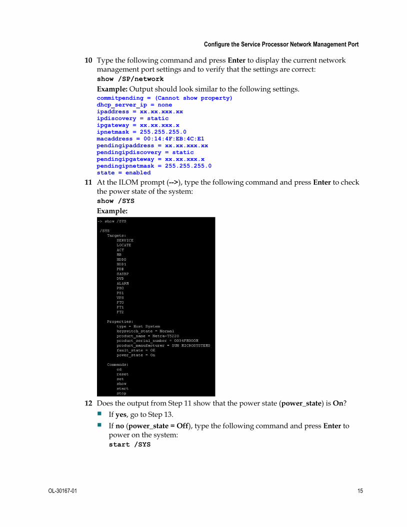
11 At the ILOM prompt (-->), type the following command and press Enter to check the power state of the system: show /SYS
Example:
12 Does the output from Step 11 show that the power state (power_state) is On?
If yes, go to Step 13.
If no (power_state = Off), type the following command and press Enter to power on the system: start /SYS

Chapter 3 Installing the DTACS Software for the First Time
16 OL-30167-01
13 At the -> prompt, type the following command and press Enter. A message asks if you want to start the console. start /SP/console -f
14 Type y for yes and press Enter. A message indicates that the console has started and instructs you to type #. to exit the console.
15 Do you see the ok prompt?
If yes, go to the next procedure in this chapter.
If no, type the following command and press Enter to send a break to the system and to display the ok prompt: set /HOST send_break_action=break
Example:
Note: You may now be required to press the # and dot (.) keys simultaneously to return to the ILOM prompt.

Install the DTACS Software
OL-30167-01 17
Install the DTACS Software This section provides the steps to install the DTACS software for the first time.
In the series of screens that follow, you will have to select a configuration parameter from a list of parameters. Use the arrow keys to navigate through your choices and make selections by pressing the Spacebar. The system usually places an X beside the selected parameter.
Important: Be certain that there are no network cables installed or connected to the DTACS at this time.
1 Insert the Maintenance DVD into the DVD drive of the DTACS.
2 At the ok> prompt, type the following command and press Enter. The server boots from the DVD. boot cdrom - install
Result: The DTACS server reboots and the installation script begins.
3 At the prompt where you specify which installation type the system is to
perform, select 1 (DTACS Server) and press Enter.

Chapter 3 Installing the DTACS Software for the First Time
18 OL-30167-01
4 At the prompt where you can change the IP address and hostname, either select the default choices or follow the on-screen instructions to make a change.
5 Monitor the output as the DVD installation process goes through the steps of
installing the individual SAI packages that are included with the DTACS software installation set.

Install the DTACS Software
OL-30167-01 19
6 Wait for the Install of SAI/TOC finished message, which indicates that the installation process completed successfully. The system reboots one more time.
7 Log in as the root user using the password provided by Cisco Services.
Important: For security purposes, upon first login, the system prompts you to change the initial root password. Follow the on-screen instructions to change the password.

Chapter 3 Installing the DTACS Software for the First Time
20 OL-30167-01
Create a dtacs User on the EC Follow these steps to create a dtacs user on the EC:
1 Type the following command and press Enter: useradd -u 503 -g500 -c "dtacs user" -d/export/home/dtacs -s
/bin/ksh -m -k/etc/skel dtacs; passwd dtacs
Results:
A dtacs user is created on the EC.
A home directory (/export/home/dtacs) is created for the dtacs user on the EC.
A prompt for the new password appears.
2 Type the new password for the dtacs user and press Enter. A prompt to retype the password appears.
3 Type the password again and press Enter.

OL-30167-01 21
Introduction
This chapter contains instructions for tasks that must be completed after DTACS software has been installed for the first time.
Important: Do not use these procedures after an upgrade. If you have upgraded the DTACS software, post-upgrade procedures are found in DTACS Post-Upgrade Procedures (on page 163).
4 Chapter 4 DTACS Post-Installation Procedures
In This Chapter
Check The Software Version Number ............................................... 22
Verify the Ownership of /dvs/dtacs/OCDL ................................... 24
Connect to the Monitor and Keyboard .............................................. 25
Verify the DTACS User ID (for New Installs) .................................. 26
Add Additional User Accounts .......................................................... 27
Set Environment Variables .................................................................. 30
Configure DTACS BOSS Proxying for the EC (Optional) ............... 34
Create DTACS WebUI Login Accounts ............................................. 35
Configure DTACS dbSync Between the DTACS and the EC Host ......................................................................................................... 39
Install Patches ........................................................................................ 45
Configuring the NTP ............................................................................ 46
Start DTACS Process and the WUI..................................................... 49
Test dbSync from the DTACS WebUI ................................................ 54
Execute the postUpgrade Script on the DTACS Host ..................... 55

Chapter 4 DTACS Post-Installation Procedures
22 OL-30167-01
Check The Software Version Number Follow these instructions to check the installed software versions on the DTACS server:
1 If necessary, insert the DTACS DVD into the DVD drive of the DTACS server.
2 Type the following command and press Enter. The system displays a listing of installed packages. /cdrom/cdrom0/sai/scripts/utils/listpkgs -i
3 Compare the version numbers shown in the output from Step 2 with the following list:
SAIcomplat -- 3.0.32
SAIcURL -- 7.20.0-1_SunOS_sparc
SAIdtacs -- 3.0.0.12
SAIdtacshelp -- 3.0.0.3
SAIDTraceToolkit -- 0.99-1_SunOS_noarch
SAIexpat -- 2.0.1-2_SunOS_sparc
SAIguisupport -- 1.0_SunOS_sparc
SAIlame -- 3.97-1_SunOS_sparc
SAIlibpcap -- 1.0.0-1_SunOS_sparc
SAIlsof -- 4.83-1_SunOS_sparc
SAImodjk -- 1.2.30-1_SunOS_sparc
SAImod-auth-xradius -- 0.4.6-1_SunOS_sparc
SAINetSNMP -- 5.5-4_SunOS_sparc
SAIntp -- 4.2.6-1_SunOS_sparc
SAIopenssl -- 0.9.8h-1_SunOS_sparc
SAIpamradius -- 1.3.17-6_SunOS_sparc
SAIperl -- 5.8.9-3_SunOS_sparc
SAIroguewave -- 1.0-4_SunOS_sparc
SAIrsync -- 2.6.9-1_SunOS_sparc
SAIscponly -- 20080308-2_SunOS_sparc
SAIsnmp -- 3.2.24-2_SunOS_sparc
SAIsox -- 12.16-1_SunOS_sparc
SAIsudo -- 1.7.2p5-1_SunOS_sparc
SAIsux -- 1.0.1-1_SunOS_noarch
SAItomcat -- 5.5.17.0-1_SunOS_sparc
SAItop -- 3.7-2_SunOS_sparc
SAIvim -- 7.2-1_SunOS_sparc
SAIwireshark -- 1.2.7-1_SunOS_sparc
SAIxalan-j -- 2.7.1-1_SunOS_noarch
SAIxercesc -- 2.8.0-1_SunOS_sparc
SFWatk -- 1.24.0,REV=110.0.4.2009.02.26.22.56
SFWcairo -- 1.8.4,REV=110.0.4.2009.02.26.23.05
SFWfirefox -- 3.0.7,REV=2009.02.27.21.43.19
SFWglib2 -- 2.18.3,REV=110.0.4.2009.02.27.14.31
SFWgtk2 -- 2.14.5,REV=110.0.4.2009.02.26.23.30

Check The Software Version Number
OL-30167-01 23
SFWpango -- 1.22.3,REV=110.0.4.2009.02.26.23.21
SFWpixman -- 0.12.0,REV=110.0.4.2009.02.26.23.01
4 Do the actual installed versions match the list shown in Step 3?
Note: The build number may differ.
If yes, you have completed this procedure.
If no, call Cisco Services and inform them of the discrepancy.

Chapter 4 DTACS Post-Installation Procedures
24 OL-30167-01
Verify the Ownership of /dvs/dtacs/OCDL Follow these steps to verify that the ownership of the /dvs/dtacs/OCDL directory is correct:
1 Log in as the root user to the DTACS server.
2 Type the following command and press Enter to change to the /dvs/dtacs directory: cd /dvs/dtacs
3 Type the following command and press Enter to view the ownership for the OCDL directory:
ls -lrt
4 Does the system indicate that the ownership is dtacs:dtacs for the OCDL directory?
If yes, the directory ownership is correct.
If no, type the following command and press Enter to change the ownership: chown dtacs:dtacs OCDL

Connect to the Monitor and Keyboard
OL-30167-01 25
Connect to the Monitor and Keyboard If you have a monitor and keyboard to install, you should set them up now. Complete the following steps to connect a monitor and keyboard to your server and to set the system environment to use the monitor and keyboard for output and input:
Important: Only perform this procedure if you are attaching a keyboard and monitor to your DTACS.
Note: You should still have access to the DTACS via the ILOM port and be logged in as the root user.
1 Type the following command and press Enter to shut down the system to the ok prompt: shutdown -y -g0 -i0
2 At the ok prompt, type the following command and press Enter. The input device is now set to the keyboard. setenv input-device keyboard
3 At the ok prompt, type the following command and press Enter. The output device is now set to the screen (monitor). setenv output-device screen
4 Attach the monitor’s video cable to the graphics card’s video port on the back of the DTACS server, and then tighten the thumbscrews to secure the connection.
5 Connect the monitor’s power cord to an AC outlet.
6 Connect the USB keyboard cable to one USB port on the back panel of the DTACS server.
7 Type the following command and press Enter. The system reboots, and the monitor and keyboard are now the active input and output devices for the server. shutdown -y -g0 -i6
8 Log in as the root user.

Chapter 4 DTACS Post-Installation Procedures
26 OL-30167-01
Verify the DTACS User ID (for New Installs) The DTACS server has enhanced security enabled. Enhanced security prevents the root user from logging in to the DTACS server remotely. You must use the DTACS server's console to log in as the root user.
Enhanced security also prevents you from directly logging into the server as the dtacs user. To access the dtacs account, you must log in as the root or administrative user and then assume the role of a dtacs user by typing the sux - dtacs command.
1 As the root user, type the following command and press Enter at the system prompt to verify that a DTACS user id exists on the DTACS server:
sux - dtacs
2 Type exit and press Enter to return to the root user.
3 Type the following command and press Enter. The system prompts you to enter a new password for the dtacs user. passwd dtacs
4 Type a password for the dtacs user and press Enter. The system prompts you to re-enter the password.
5 Re-type the password for the dtacs user and press Enter.
6 Go to Add Additional User Accounts (on page 27) to create a new user ID with an administrative role.

Add Additional User Accounts
OL-30167-01 27
Add Additional User Accounts This procedure allows you to create UNIX shell login accounts, as well as DTACS WebUI login accounts. If you want to create ONLY a WebUI account, skip this procedure and go to Create DTACS WebUI Login Accounts (on page 35).
If the procedure Verify the DTACS User ID (for New Installs) indicated that the dtacs user does not exist, use this procedure to create a dtacs role.
After you verify the user ID, use this procedure to create DTACS user accounts with other roles.
Follow these steps to add new user roles for the DTACS server:
1 Log in to the DTACS server as the root user. The password prompt appears.
2 Type the password for the root user and press Enter. The root prompt appears.
3 Type the following command and press Enter. A menu similar to the following example appears. /dvs/admin/create_users
Example: -------------------------- Choose Type of User to Add -------------------------- 1: Add Regular User (has no DTACS privileges) 2: Add Operator (has DTACS read privileges) 3: Add Administrator (has DTACS read & write privileges) Please enter choice or 'Q' to exit:
Notes: Review the following descriptions of the options available in Step 3 before proceeding.
Option 1 creates a regular UNIX login to the DTACS server.
Option 2 creates an operator user who has read privileges.
Option 3 creates a DTACS administrator user who has read/write privileges and can log in to the DTACS WebUI administrative console to perform UI administrative tasks.
Important: Select the option that pertains to your needs. The examples in the rest of this procedure assume that you select Option 3.
4 Type 3 to add an administrator user and press Enter. A message prompts you to enter a username.

Chapter 4 DTACS Post-Installation Procedures
28 OL-30167-01
5 Type a username and press Enter. A message prompts you to continue.
6 Type y to continue and press Enter. A message prompts you to enter a new
password.
7 Type the appropriate password and press Enter. A prompt to re-enter the new password appears.
8 Re-type the password and press Enter. The new user is created.
Notes:
This is the password for the UNIX shell login.
The system prompts you for the password yet again, and this time the password refers to the WebUI login.
9 Type the password for the WebUI login.
Note: The username and password that you used for the UNIX login can also be used for the WebUI.

Add Additional User Accounts
OL-30167-01 29
10 Re-type the password for the WebUI login again and press Enter.
Result: The script exits.

Chapter 4 DTACS Post-Installation Procedures
30 OL-30167-01
Set Environment Variables By default, there will only be a few entries in the .profile file. These variables are sufficient for system operation. For most environment variables, the system selects the default values from the code or from other files. Changes to the .profile file may not be necessary on your system. Check with the network administrator of the site you are upgrading for any required changes.
Notes:
You only need to complete this procedure if you are installing a new DTACS for the first time. If you are upgrading an existing DTACS, the .profile file from the earlier release is available. If required, you can add or modify entries in it.
The default values are appropriate in most circumstances. Unless otherwise directed, you should choose the default values during initial setup and adjust them later, if necessary.
Important: Whenever you change an environment variable in the .profile file, you must then source the file. Type the following command and press Enter. (Be sure to type a space between the first . and /.) Then run the dtacsStop, dtacsKill, and dtacsStart commands as dtacs user, if the process are already running.
. /export/home/dtacs/.profile
Variable Description
AMM_PERCENT_DATARATE Used by ammDistributor to determine the maximum bandwidth to use as a percentage of the AMM IP stream datarate.
The default rate is 80 percent and the allowed range is 20 to 80 percent.
COMM_MULTICAST_TTL Overrides the Time-To-Live for IP packets sent by the dataPump.
IP_STREAMER_TTL Overrides the Time-To-Live for IP packets sent by dtacsIpStreamer. The default is 10.
NIT_MSG_RATE (units ms)
Specifies the number of seconds between DTACS system updates of the SCTE-65 Network Information Table (NIT).
The default value is 5000 ms, which is once every 5 seconds.
NTT_MSG_RATE (units ms)
Specifies the number of seconds between DTACS system updates of the SCTE-65 Network Text Table (NTT).
The default value is 120,000 ms, which is once every 120 seconds.

Set Environment Variables
OL-30167-01 31
Variable Description
SI_INSERT_RATE (units ms)
Specifies the number of seconds between DTACS system updates of the SCTE-65 Short Virtual Channel Table (S-VCT).
The default value is 15,000 ms, which is once every 15 seconds.
Note: This variable determines the rate of the Virtual Channel Map (VCM) and the Source Name Subtable (SNS). The VCM is part of the SVCT, but the SNS is not part of the table.
SYSTEM_TIME_RATE (units seconds)
Specifies the number of seconds between DTACS system updates of the SCTE-65 System Time Table (STT).
The default value is 5 seconds.
USP_GUIDE_DATA_PID_SECS (units seconds)
Specifies the number of seconds between DTACS transmissions of the Guide Data PID AMM. This value overrides the default of 30 seconds.
USP_MAX_SITE_ERRORS Specifies the limit of USP site announce AMMs that have a different controllerId than the one with which the DTA is provisioned.
Once this limit is reached, the DTA will not provide audio and video services.
USP_OSD_MESSAGE_SECS (units seconds)
Specifies the number of seconds between the DTACS system sending the On Screen Display AMM. This value overrides the default of 15 seconds.
USP_POST_RESET_WAIT_SECS
(units seconds)
Overrides the time to wait after sending Reset/Boot AMMs of the DTA before sending Config/Connect AMMs. The default is 120 seconds.
USP_REPEAT_CONNECT Turns on periodic retransmission of the Connect AMM for activated DTAs. The default is not to send the Connect AMMs. The variable must be set to an non-zero decimal value, otherwise it is ignored.
USP_SITE_ANNOUNCE_SECS (units seconds)
Overrides the time between transmission of the Site Announce AMM. The default is 20 seconds.

Chapter 4 DTACS Post-Installation Procedures
32 OL-30167-01
Variable Description
USP_TIMEOUT_POLICY Specifies whether the message timeout counter will reset whenever the DTA receives certain messages. Possible values are:
BOTH: The counter resets whenever the DTA receives either a broadcast message (such as site announce) or a unicast message (such as config). This is the default value.
UNICAST: The counter only resets when the DTA receives a unicast message.
DNCS_BOSS_PROXYING Enables proxy of the BOSS calls to the EC on the DTACS. The default behavior is to disable this feature. DTACS handles seven BOSS transactions: ModifyDhctConfiguration, ModifyDhctAdminStatus, SetPin, ResetClientNvm, BootDhct, DhctInstantHit, DeregisterDhct for all DTA MAC addresses.
The feature can be enabled by setting the variable DNCS_BOSS_PROXYING to 1 in the /dvs/dtacs/etc/bossServer.cfg file. This feature helps the operator decide how the BOSS transactions that are not intended for the DTA MAC addresses are handled. When the feature is enabled, all transactions except the seven transactions of ModifyDhctConfiguration, ModifyDhctAdminStatus, SetPin, ResetClientNvm, BootDhct, DhctInstantHit, DeregisterDhct will be simply forwarded as is to the EC. The above-mentioned seven transactions will be forwarded to EC only if the MAC Address of the transactions correspond to a DHCT, or else they are forwarded to dtacsBossServer for processing within DTACS.
BOSS_CONNECTION_TIMEOUT_SECS (seconds)
Specifies the number of seconds after which an out-of-use connection is considered stale. A value of 0 indicates that the timeouts do not apply.
Note: By default, this environmental variable is not set and the connections do not timeout. To enable this feature, a value greater than 0 needs to be set for the environment variable. The feature is designed to overcome the issue where the TCP connections are dropped by the firewalls between the Billing System and the DTACS after some idle time. The feature allows the DTACS to time out on unused connections and close them.

Set Environment Variables
OL-30167-01 33
Variable Description
UI_POLL_INTERVAL (seconds) The DTACS WUI polls the status of the process every UI_POLL_INTERVAL. This is set to 15 seconds by default. When you start or stop a DTACS service, the process status WUI on the DTACS system should reflect the status of the processes within about 15 seconds. The default value should be modified only if response issues are seen on the system.
MAX_CAROUSEL_CYCLE_SAFE_LIMIT (units seconds)
Specifies the safe limit for the Image Carousel Cycle Time in number of seconds beyond which the Indicator light next to the Image Carousel Cycle Time in the Image Management Web UI turns from green to yellow. The default value is 150 seconds.
MAX_CAROUSEL_CYCLE_THRESHOLD
_LIMIT (units seconds) Specifies the threshold limit for the Image Carousel Cycle Time in number of seconds beyond which the Indicator light next to the Image Carousel Cycle Time in the Image Management Web UI turns from yellow to red. The default value is 300 seconds.

Chapter 4 DTACS Post-Installation Procedures
34 OL-30167-01
Configure DTACS BOSS Proxying for the EC (Optional)
You can set up the billing system to send BOSS transactions to the EC, if you prefer. The DTACS will then forward any non-DTA-related transactions to the associated EC. Follow these steps to configure DTACS BOSS proxying for the EC.
Note: Your system may or may not use a BOSS proxy. If it does not, skip this section and go to the next procedure in this chapter.
1 Type the following command and press Enter to change to the /dvs/dtacs/etc directory: cd /dvs/dtacs/etc
2 Type the following command and press Enter to see if the bossServer.cfg file exists: ls -l *bossServer.cfg*
3 Does the system indicate that the bossServer.cfg file exists?
If yes, then you do not need to do anything else. Go to the next procedure in this chapter.
If no, go to Step 4.
4 Type the following command and press Enter to create a new bossServer.cfg file from the sample configuration file provided:
cp bossServer.cfg.sample bossServer.cfg
5 In a text editor, open the bossServer.cfg file.
6 In the bossServer.cfg file, set the DNCS_BOSS_PROXYING parameter to 1 to enable DTACS to proxy non-DTA-related BOSS transactions for the EC.
Example: DNCS_BOSS_PROXYING = 1
7 Save and close the bossServer.cfg file.
8 Type the following command and press Enter to view the ownership for the bossServer.cfg file: ls -lrt bossServer.cfg
9 Does the system indicate that the ownership is dtacs:dtacs?
If yes, the directory ownership is correct.
If no, type the following command and press Enter to change the ownership. chown dtacs:dtacs bossServer.cfg
10 Bounce (stop and restart) both the dtacsBossProxy and dtacsBossServer processes if they have already started.

Create DTACS WebUI Login Accounts
OL-30167-01 35
Create DTACS WebUI Login Accounts In this procedure, we create login accounts ONLY to the WebUI. This does not apply to UNIX shell login accounts.
1 Log in to the system as the root user.
2 Type the following command and press Enter:
/usr/apache2/bin/htdigest /etc/apache2/user-
conf/SAIdtacs.digest "Cisco DTACS" [username]
Notes:
This is a single command.
Substitute the user account name for [username]. Do not type the brackets in the command.
3 Type the new web interface password for the user and press Enter.
4 Type the new password again and press Enter. The system compares the two password entries.
5 Did the They don't match, sorry message appear?
If yes, the two passwords do not match. Repeat this procedure from Step 2.
If no, the system prompt is returned and you are finished with this procedure.
Delete DTACS WebUI Accounts
Use this procedure to delete DTACS WebUI login accounts.
1 Log in to the system as the root user.
a At the prompt, type su - and press Enter.
b Type the root password and press Enter.
2 Open the /etc/apache2/user-conf/SAIdtacs.digest file with a text editor.
3 Delete, or comment out, the entire line that contains the username for which you want to disable access.
4 Save and close the SAIdtacs.digest file.
Configure Remote Access to the DTACS Web Interface
Complete the following steps to access the DTACS web interface remotely.
Important: You must obtain the hostname and IP address for your corporate network-facing interface from your System Administrator to complete this procedure. The following examples use dtacs1 as the hostname and 10.78.203.57 as the IP address. These are examples, only.
1 Log in to the DTACS as the root user.
2 Open the /etc/hosts file with a text editor.
Chapter 4 DTACS Post-Installation Procedures
36 OL-30167-01
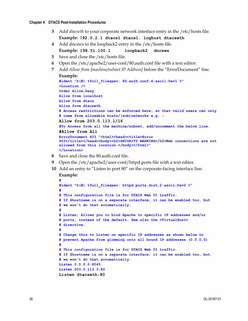
3 Add dtacseth to your corporate network interface entry in the /etc/hosts file.
Example: 192.0.2.1 dtacs1 dtacs1. loghost dtacseth
4 Add dncsws to the loopback2 entry in the /etc/hosts file.
Example: 198.51.100.1 loopback2 dncsws
5 Save and close the /etc/hosts file.
6 Open the /etc/apache2/user-conf/80.auth.conf file with a text editor.
7 Add Allow from [machine/subnet IP Address] before the “ErrorDocument” line.
Example: #ident "@(#) %full_filespec: 80.auth.conf,4:ascii:Da=1 %" <Location /> Order Allow,Deny Allow from localhost Allow from dtacs Allow from dtacseth # Access restrictions can be enforced here, so that valid users can only # come from allowable hosts/(sub)networks e.g. : Allow from 203.0.113.1/16 #To Access from all the machine/subnet, add/uncomment the below line. #Allow from All ErrorDocument 403 "<html><head><title>Error
403</title></head><body><h2>SECURITY WARNING</h2>Web connections are not
allowed from this location.</body></html>" </Location>
8 Save and close the 80.auth.conf file.
9 Open the /etc/apache2/user-conf/httpd.ports file with a text editor.
10 Add an entry to “Listen to port 80” on the corporate-facing interface line.
Example: # #ident "@(#) %full_filespec: httpd.ports.dist,2:ascii:Da=2 %" # # This configuration file is for DTACS Web UI traffic. # If $hostname is on a separate interface, it can be enabled too, but # we won't do that automatically. # # Listen: Allows you to bind Apache to specific IP addresses and/or # ports, instead of the default. See also the <VirtualHost> # directive. # # Change this to Listen on specific IP addresses as shown below to # prevent Apache from glomming onto all bound IP addresses (0.0.0.0) # # This configuration file is for DTACS Web UI traffic. # If $hostname is on a separate interface, it can be enabled too, but # we won't do that automatically. Listen 0.0.0.0:8045 Listen 203.0.113.3:80 Listen dtacseth:80

Create DTACS WebUI Login Accounts
OL-30167-01 37
11 Save and close the httpd.ports file.
12 Type the following command and press Enter to restart the Apache server process: svcadm restart http
Supported Browser
When viewing the Web UIs (WUIs) in DTACS , we recommend using Firefox Version 3.0.7 for Solaris and Version 3.6.28 for Windows.
Firefox Version 24 ESR is supported for the DTACS 3.0.0.18P1 release, and beyond, for Windows.
Notes:
Cisco engineers tested the WUIs with Firefox 3.0.7 on Solaris and Version 3.8.18 on the Windows operating systems.
Firefox Version 4.0 and later is not supported until DTACS 3.0.0.18.
Firefox Version 24 ESR is supported for the DTACS 3.0.0.18P1 release, and beyond. If you are using Firefox Version 24 ESR, refer to Correcting Dialog Box Errors in Firefox Version 24ESR (on page 222).
The Safari and Opera browsers for Windows are not supported.
Accessing the Administrative Console 1 Navigate to the following location in the web browser on your computer:
http://[DTACS IP Address]/dtacs/
Example: http://192.0.2.1/dtacs
Result: A login prompt appears.

Chapter 4 DTACS Post-Installation Procedures
38 OL-30167-01
2 Type your DTACS Administrator username and password, and click OK.
Result: The DTACS Administrative Console opens.

Configure DTACS dbSync Between the DTACS and the EC Host
OL-30167-01 39
Configure DTACS dbSync Between the DTACS and the EC Host
This procedure provides steps to check the DTACS hosts and make required changes for the dtacsdbsync process to work with the associated EC host.
Verify User Ownership and Group Permissions
Important:
This step takes place in the root xterm window of the DTACS server.
The example that follows may differ from the output on your system; however, it should be similar.
Do not change the group ID for any group.
Complete this step to verify that the ownership for dncs, dtacs, and dncsSSH users are correct on the DTACS server and also to verify that the dncs user belongs to the dncs group and the dtacs user belongs to the dtacs group.
Type the following command and press Enter to verify directory ownership for the dncsSSH, dncs, and dtacs users:
ls –ltr /export/home
Example: Output should be similar to the following example:
# ls –ltr /export/home
.
.
.
drwxr-x--- 3 dncsSSH dtacs 512 Feb 22 15:30 dncsSSH
drwxr-x--- 6 dncs dncs 512 Feb 23 07:25 dncs
drwxr-xr-x 7 dtacs dtacs 512 Mar 3 10:19 dtacs

Chapter 4 DTACS Post-Installation Procedures
40 OL-30167-01
Open an xterm Window on the EC and DTACS Servers
To configure the DTACS server to run on the EC system, you will need to add or modify specific configurations and files on both the DTACS server and the EC. For this reason, we recommend opening two root xterm windows: one that accesses the EC server and one that accesses the DTACS server.
Important: Once this procedure is completed, we will refer to either the root xterm window on the DTACS or the EC server for the remaining procedures in this guide.
Complete the following steps to open one root xterm window on each server:
1 Open two xterm windows on the EC system.
2 In one xterm window, complete the following steps to log in as the root user on the EC.
a Type su – and press Enter. You are prompted to enter your password.
b Type the root password and press Enter. The root prompt appears.
3 In the other xterm window, access your DTACS server by entering the following command: ssh –X [userID]@[dtacsIP]
Notes:
Substitute your user ID that was created on your DTACS server for [userID].
Substitute the IP address for the DTACS server for [dtacsIP].
Do not include any brackets in the command.
4 In the DTACS window, type su – and press Enter to change to the root user; then enter the password when prompted.
Add DTACS as a Trusted Host on the EC Server
Important: All steps in this procedure take place in the root xterm window on the EC server.
1 In the root xterm window on the EC server, verify the name of the DTACS server by typing the following command and pressing Enter: grep [dtacsIP] /etc/hosts
2 Locate the dtacs entry and record the first entry that follows the IP address for DTACS in the space provided.
Host Name of DTACS Server: __________
Example: In the following example, the output shows that the hostname of the DTACS server is dtacshost. # grep 192.0.2.1 /etc/hosts
192.0.2.1 dtacshost dtacs
Notes:
The first name listed after the IP address is the hostname of the DTACS server; the other names are aliases.
This is only an example. The IP address and entries for dtacs may differ in your /etc/hosts file.

Configure DTACS dbSync Between the DTACS and the EC Host
OL-30167-01 41
3 Check the etc/hosts.equiv file for the following [dtacshost] entries. If these entries do not exist, add them. [dtacshost] dtacs
[dtacshost] dncs
[dtacshost] root
Important: Substitute the hostname you recorded in Step 2 for [dtacshost]. Do not include the brackets.
4 Save and close the file.
Create the Private and Public Keys Between the EC and DTACS Servers
This procedure includes the steps that add the private/public keys between the EC and DTACS server. This procedure is necessary because of the Enhanced Security feature enabled in this system release.
1 Record the hostname for the DTACS server that you identified in Step 2 of the Add DTACS as a Trusted Host on the EC Server (on page 40) in the space provided.
Host Name of DTACS Server: ________________________________________
2 In the root xterm window of the DTACS server, open the /export/home/informix/etc/sqlhosts file in a text editor.
3 Open a new line at the end of the file and add the following entry: dncsatmDbServer ontlitcp dncsatm informixOnline
4 Save and close the sqlhosts file on the DTACS server.
5 In the root xterm window of the EC server, check the /export/home/informix/etc/sqlhosts file for the following entry. If the entry does not exist, add it. dncsatmDbServer ontlitcp dncsatm informixOnline
6 Save and close the file on the EC server.
7 In the root xterm window of the EC server, check the /export/home/informix/etc/onconfig file for the dncsatmDbServer entry at the end of the DBSERVERALIASES variable. Add the variable if it does not exist.
Important: This is an example; the entries for DBSERVERALIASES may differ on your system. Ensure that dncsatmDbServer is the last entry in this line.
Example:

Chapter 4 DTACS Post-Installation Procedures
42 OL-30167-01
8 Did you modify the onconfig file in the previous step?
If yes, then type the following command and press Enter to start the Informix listener for the dncsatmDbServer: onmode –P start dncsatmDbServer
If no, continue with Step 9.
9 In the root xterm window on the EC server, type the following command and press Enter. The Enter the host name of the site you are adding message appears. siteCmd -S
10 Type the hostname of the DTACS server (recorded in Step 2) and then press
Enter. The Enter the IP address of the site you are adding message appears.
Example: dtacshost
Note: Replace the hostname in this example with the actual hostname for your DTACS server (recorded in Step 2).
11 Type the IP address of the DTACS server (used in Step 1) and then press Enter. The Do you want to continue? message appears.
Example: 192.0.2.1
Note: Replace the IP address in this example with the actual IP address for your DTACS server (used in Step 1).
12 Type y and press Enter.
Results:
A message appears that states that the system is backing up and adding an entry to the /etc/hosts file.
The Do you want to continue? message appears and you are prompted for the root password of the DTACS server.
13 When prompted, type the root password for the DTACS server and press Enter. The system displays a series of messages about generating various keys and a Done message appears when it is finished.
14 Type the following command and press Enter to change to the dncs user:
Note: You should still be working in the root xterm window of the EC. sux - dncs
15 Type the following command and press Enter:
ssh -X -i /export/home/dncsSSH/.ssh/siteKey dncsSSH@[DTACS
hostname]
Note: Substitute the hostname of your DTACS server (recorded in Step 1) for [DTACS hostname]. Do not include the brackets.
Result: The system logs you on to the DTACS server as dncsSSH user. You are now connected to the DTACS server and the host for the DTACS server is permanently added to the list of known hosts on the EC.
16 Type su - and press Enter. The password prompt appears.
17 Type the root password for the DTACS server and press Enter.
18 Type the following command and press Enter to change to the dncs user: sux - dncs

Configure DTACS dbSync Between the DTACS and the EC Host
OL-30167-01 43
19 Type the following command and press Enter: ssh -X -i /export/home/dncsSSH/.ssh/siteKey dncsSSH@dncsatm
Result: The system logs you on to the EC as dncsSSH user and the Are you sure
you want to continue connecting? message appears.
Note: If an error message appears about conflicting keys, open the /export/home/dncs/.ssh/known_hosts file, and delete the entry that corresponds to the dncsatm. Then, save the file and repeat this step.
20 Type y and press Enter. You are now connected to the EC. The hostname for the EC is permanently added to the list of known hosts on the DTACS server.
21 Type exit and press Enter until the xterm windows close and you are entirely logged out as dncsSSH user on the DTACS and the EC servers. Your current window should be the root user in the EC xterm window.
Revise the sshd_config File on the DTACS Server
Important: All steps in this procedure take place in the root xterm window of the DTACS server.
1 Open the /etc/ssh/sshd_config file in a text editor.
2 Edit the PermitRootLogin yes entry to the following: PermitRootLogin no
3 Save and close the sshd_config file.
4 Type the following command and press Enter to restart the SSH service. svcadm restart ssh
Test dbSync on the DTACS Server
Important: All steps in this procedure take place in the root xterm window of the DTACS server.
Complete the following procedure to ensure that the DTACS database successfully syncs with the EC database.
1 In the root xterm window of the DTACS server, type the following command and press Enter to switch to the dncs user: sux – dncs
2 Type the following command and press Enter to establish the correct DTACS environment: . /dvs/dtacs/bin/dtacsSetup
Note: Make sure that there is a space between the period (.) and the forward slash (/).

Chapter 4 DTACS Post-Installation Procedures
44 OL-30167-01
3 Type the following command and press Enter to verify that you can access the EC database: dbaccess dncsdb@dncsatmDbServer -
Example: Output should be similar to the following example: $ dbaccess dncsdb@dncsatmDbServer -
Database selected
>
4 Press the Ctrl and c (Ctrl-C) keys simultaneously to exit from the dbaccess utility.
5 Type the following command and press Enter to initiate a synchronization of the DTACS database: dtacsdbsync –S
6 Did a Dbsync Succeeded message appear at the end of the script?
If yes, the synchronization was successful. Go to the next procedure.
If no, contact Cisco Services for assistance.

Install Patches
OL-30167-01 45
Install Patches If you have any patch software for the DTACS server, install it now. Instructions for installing the patch software should accompany the DVD that contains the software.

Chapter 4 DTACS Post-Installation Procedures
46 OL-30167-01
Configuring the NTP
Configuring the NTP Server
Complete the following steps to sync the NTP server on the DTACS server with the time server on the EC.
1 Open an xterm window.
2 Type the following command and press Enter to verify that xntpd is not running before you continue: pgrep -lf ntp
Note: If xntpd is running, a message similar to the following will appear. 136 /dvs/tools/ntp/bin/ntpd -c /etc/inet/ntp.conf -p /etc/ntp.pid -l
/var/adm/log/
3 As the root user, type the following command and press Enter to verify network connectivity to the NTP server: /dvs/tools/ntp/bin/ntpdate -d <IP of NTP Servers>
Example: /dvs/tools/ntp/bin/ntpdate -d 192.0.2.1
Results: The system should respond with both transmit and receive packets followed by time information sent from the NTP server. If the final line of the output states "no server suitable for synchronization found", then either a problem exists with the NTP server or a network issue is preventing a connection. Verify the IP address with your Network Administrator and attempt this command again. If you are still unable to resolve this problem, contact Cisco Services for assistance.
4 Type su - and press Enter to change to the root user.
5 Use the vi editor to add the NTP server IP addresses to the /etc/hosts file. Add the IP and hostname of each NTP server.
Example: 192.0.2.1 dncsatm
Notes:
There should already be a dncsatm entry in the /etc/hosts file.
You can also include additional NTP server entries in the /etc/hosts file.
6 Type the following command and press Enter to change to the /etc/inet directory. The /etc/inet directory becomes the working directory. cd /etc/inet
7 Type the following command and press Enter to make a copy of the existing ntp.conf file: cp ntp.conf ntp.conf.bak

Configuring the NTP
OL-30167-01 47
8 Use the vi editor to edit the ntp.conf file so that the first lines contain an entry for each NTP server that you choose to use.
Example: server dncsatm mode 10 prefer server 203.0.113.3 #local clock will engage if GPS fails fudge dncsatm stratum 13 driftfile /etc/ntp.drift
Note: Simply replace the IP address with the NTP server name defined in the /etc/hosts file.
9 Type :wq! to save these changes and exit the vi editor.
10 Type the following command and press Enter to stop the ntpd process:
/etc/init.d/xntpd stop
11 Type the following command and press Enter to re-start the ntpd process. /etc/init.d/xntpd start
12 Type the following command and press Enter to verify that the ntpd process is running. pgrep -fl ntp
Example: 29840 /usr/local/xntpd/ntpd -c /etc/inet/ntp.conf -p /etc/ntp.pid -l /var/adm/log/ntp
13 Type ntpq and press Enter to display the ntpq prompt.
14 Type peers and press Enter to verify the EC is the clock being used.
Example: remote refid st t when poll reach delay offset disp
======================================================================
LOCAL(0) LOCAL(0) 5 l 21 64 377 0.00 0.000 0.94
*dncsatm 198.51.100.1 4 u 28 64 377 1.46 -15.339 0.94
Notes:
The appearance and content of the results will vary according to your System release version.
The asterisk (*) in front of the dncsatm (as shown in the above example) indicates that the DTACS is using the EC ATM as a reference clock and that the DTACS server is synchronized to the EC.
Important: If the asterisk (*) is in front of LOCAL, then the DTACS is not synchronized to the EC. It is synchronized with the hardware clock on the server. This situation must be corrected immediately.

Chapter 4 DTACS Post-Installation Procedures
48 OL-30167-01
15 At the ntpq> prompt, type lass and press Enter.
Results: A result similar to the following examples appear on the screen.
Example: ind assID status conf reach auth condition last_event cnt
===========================================================
1 27724 9014 yes yes none insane reachable 1
2 27725 9614 yes yes none sys.peer reachable 1
Note: The device numbers listed in the first column of the following output correspond with the devices listed in the ntpq> peers output from the example in Steps 13 and 14.
16 Use the date command on the EC and DTACS servers to verify the time on both servers.
EC Example: Mon Nov 23 15:36:46 EST 2009
DTACS Example: Mon Nov 23 15:31:15 EST 2009
Note: In this example above, the DTACS time is 5min 31sec behind the EC. NTP will automatically synchronize the servers once the time difference is less than two minutes.
17 If you need to synchronize the servers, type date hhmm.ss (where hhmm.ss is the target time on the EC) and press Enter to reset the DTACS time. The DTACS time is reset to match the EC.
Example: # date 1536.46

Start DTACS Process and the WUI
OL-30167-01 49
Start DTACS Process and the WUI
Before Using the DTACS WUIs
Before you start using the DTACS WUI, note these important points:
Understanding Channel Maps
The channel map of a BSG is determined by the channel map of the EC Hub ID that is associated with the BSG.
Understand PID Routes
PID routes are created automatically for the ports that are part of the BSG. Therefore, you must configure VCTs before you edit PID Routes.
Understand Running Multiple Instances of Firefox
When you launch multiple Firefox windows from your system, multiple sessions with the same profile will be created. This creates session conflicts. To understand how to avoid this by using different profiles for different session, refer to the following procedures in Appendix B.
Creating a New Firefox Profile in Solaris (on page 215)
Creating a New Firefox Profile in Windows (on page 218)
Starting DTACS Processes
Important: If you attempt to start a DTACS process from the command line while all of the DTACS server processes are already running, you could cause the process to core dump or otherwise disrupt the normal operation of the DTACS server. If this occurs, you should send the core files and logs to Cisco for evaluation.
1 Type the following command and then press Enter to assume the dtacs role. A prompt for the role's password appears.
sux - dtacs
Important: If you have not yet created a password for the dtacs user, open a new window and switch to root. Type passwd dtacs and enter a password when prompted. Re-enter the password when prompted.
2 Type the dtacs password and press Enter. A system prompt appears and /export/home/dtacs becomes the active directory.
3 Type the following command and press Enter. The dtacs processes start. dtacsStart
Important: Be certain that you are starting the DTACS processes as the dtacs user. Do not start the processes as the root user.

Chapter 4 DTACS Post-Installation Procedures
50 OL-30167-01
4 Type the following command and press Enter to start the software and launch the interface, if the DTACS WUI has not already launched: dtacsWUIStart
Results:
If you are launching Firefox for the first time, click Install Now to install the application.
The message Launching the DTACS Web UI page in Firefox appears.
A prompt for the DTACS User Name and Password appears.
5 Type the User Name and Password and click OK. The DTACS web user
interface (WUI) appears.
6 Before proceeding to access the Web UI pages, complete the steps in Clearing the
Firefox Browser Cache (on page 212).

Start DTACS Process and the WUI
OL-30167-01 51
7 Click the Process Status tab to view the processes.
8 Select one of the following to view status processes:
Click Show to view the status of the processes in the current window.

Chapter 4 DTACS Post-Installation Procedures
52 OL-30167-01
Click Pop-Out to view the status of the processes in a separate window.
Each process running on the DTACS is listed next to a green, yellow, or red indicator. The color of the indicator shows the status of the process.
Red means a process has stopped.
Green means a process is running.
Yellow means a process has paused.
Note: The color of the indicator may lag slightly behind the actual status of the process. If you stop or start a process, it may take a few seconds before the indicator changes color to show the change in status.
DTACS Processes
The following table briefly describes each of the DTACS processes.
Process Description
ammDistributor This process transmits Authorization Management Messages (AMMs) to Digital Transport Adapters (DTAs).
dataPump This process pumps out encoded images to a specific IP/port combination.
dtacsBossProxy This process handles backend processing of BOSS transactions that are not supported by DTACS.
dtacsBossServer This process provides BOSS interfaces to DTACS.
dtacsCvtMgr This process works with CD2-CVT files. It allows you to create, edit, delete and transmit CD2-CVT file data.

Start DTACS Process and the WUI
OL-30167-01 53
Process Description
dtacsNeMgr This process provisions and maintains network configurations that are used to setup PID routes and insert Simple Content Protection and Multi-Program Keys.
dtacsIpStreamer Transmits data supplied by other DTACS processes as MPEG elementary streams to specified IP addresses (multicast or unicast).
dtacsSiManager This process generates SI and channel map data.
dtacsUIServer This process proxies WUI requests to the appropriate back-end process(es) and the Informix database. The dtacsUIServer process also returns responses from back-end processes and the database to the WUI.
dtaManager This process provisions and manages DTA devices.
eventManager This process provides a way to notify system components of events.
logManager This process is an internal process that manages debug logging levels of DTACS packages.
ocdlManager This process handles requests from the WUI. It creates and manages associations and related CVTs, encodes images and interacts with the database to persist related data.
scpManager This process provides key management for Simple Content Protection (SCP).

Chapter 4 DTACS Post-Installation Procedures
54 OL-30167-01
Test dbSync from the DTACS WebUI 1 Click Sys Config in the WUI. The DTACS System Configuration window opens.
2 Click the DB Sync tab and then click DB Sync to initiate the DTACS database synchronization process.
Note: After a few moments, the Status in the DB Sync Status History table is refreshed automatically every three seconds.
3 Select one of the following options:
If the Status is In Progress, wait a few seconds for the status to refresh.
Note: The time taken by the DB Sync process is based upon the amount of data that needs to be synchronized from the EC. We recommend that operators wait to access the DTACS user interfaces until after this process has completed because there may be much data that needs to be updated.
If the Status is Completed and if the entry in the DB Sync End Time column is current, then the synchronization was successful. Go to the next procedure in this chapter.
If the Status is Failed, and if the description reveals that the synchronization is still in progress, repeat this procedure after a few seconds.
Note: Contact Cisco Services if you are not able to synchronize the database successfully.

Execute the postUpgrade Script on the DTACS Host
OL-30167-01 55
Execute the postUpgrade Script on the DTACS Host
The DTACS postUpgrade script performs post-install and post-upgrade checks, enables cron jobs, checks for filesystem space utilization, as well as other functions.
1 Insert the DTACS DVD into the DVD drive of the DTACS server.
2 Type the following command and then press Enter. A list of the mounted file systems appears. df -n
Note: The presence of /cdrom in the output confirms that the system correctly mounted the DVD.
3 As the root user, type the following command and press Enter to source in the DTACS environmental variables: . /dvs/dtacs/bin/dtacsSetup
4 As the root user, type the following command and press Enter. A confirmation message appears. /cdrom/cdrom0/sai/scripts/postUpgrade
5 Type y and press Enter. The system executes the postUpgrade script.


OL-30167-01 57
Introduction
This chapter explains how to provision the Cisco DTACS after you have installed the software for the first time.
5 Chapter 5 Provision the DTACS
In This Chapter
Configure the DTACS System ............................................................ 58
Configure Daylight Saving Time ........................................................ 62
Manage Virtual Channel Tables ......................................................... 64
Provisioning a Broadcast Service Group ........................................... 71
Setting Up IP Streams ........................................................................... 75
Edit User-Defined PID Routes ............................................................ 81
Manage DTA Types .............................................................................. 92
Common Download ............................................................................. 96
Image Management ............................................................................ 101
Manage CVTs ...................................................................................... 103
Manage Download Groups ............................................................... 106
Associate CVTs .................................................................................... 110
Configure Source-SCID Mapping .................................................... 115
Manage Authorization Codes ........................................................... 119
Manage DTAs ...................................................................................... 126
Run the setGroupIdToDta Script ...................................................... 141

Chapter 5 Provision the DTACS
58 OL-30167-01
Configure the DTACS System To begin configuring the DTACS, click Sys Config on the DTACS WUI.
Result: The DTACS System Configuration window opens.

Configure the DTACS System
OL-30167-01 59
Edit a System Configuration
Follow these steps to edit a DTACS system configuration.
1 Click Edit in the DTACS System Configuration window.
Result: The Edit DTACS System Configuration window opens.
2 Click in the field that you want to edit. Use the scroll bar to access fields that are
not visible.
Note: The All Services VCT list includes all the VCTs configured in the VCT mapping. To add a VCT, refer to Add a New VCT (on page 64).
Refer to the following table for information on how to configure the various fields.
Field Description
System Parameters
Max Number of Virtual Channel Tables (VCT)
Maximum number of VCTs used within a DTACS.
Note: Must be a whole number between 1 and 120.
All Services VCT Used when a DTA device has been enabled but has not yet been assigned a valid VCT ID.
Guide Data PID (hex) The PID that the DTACS uses to send guide data to DTAs.

Chapter 5 Provision the DTACS
60 OL-30167-01
Field Description
OSD Message Parameters
Use the following information to configure OSD messages:
To use the default message, select the Use Default option and leave the other fields unselected or blank.
To use a custom phone number, deselect the Use Default option. Then, select the Phone number field and add a phone number to the OSD Message field.
To use a custom message, deselect the Use Default and Phone number fields. Then, add the message to the OSD Message field. The message contains a sequence of displayable 7-bit ASCII characters. Valid characters are in the range of 0x20 to 0x7D.
Note: The Use Default, Phone number, and OSD Message fields are also applicable to the ASM, SIM, and NAM messages.
AMM Parameters (Authorization Management Message
AMM Time Window (days)
Used to calculate the expiration date of the AMM.
AMM PID (hex) A hexadecimal value inserted into the header of each AMM. This value indicates that the message contains AMM data.
SCID Time Window (days)
This value specifies the amount of time in days for which the SCID cannot be reused after it has been deleted.
Site Announce Message Parameters
Use Universal Location ID If selected (a check mark appears in the box), all Site Announcement messages from this DTACS are overridden with the Location ID of 0 (zero).
Important: This is a special case used for splitting or merging plants. Contact Cisco Services for more information.
Provider Phone Number The service provider phone number.
Configuration Message Parameters
Location ID (hex) A unique identifier for a headend associated with a specific DTACS. This ID is inserted into Site Announcement broadcast messages and DTA Network Config unicast messages.
Valid values: A hexadecimal number from 0x00000001 to 0xFFFFFFFF. Zero is an invalid entry.

Configure the DTACS System
OL-30167-01 61
Field Description
Activation Timeout (hours)
The DTACS periodically sends this value to DTAs within AMM messages. This is known as refreshing the timeout value.
If a DTA receives timeout values within this specified time period (in hours), the DTA remains activated.
If a DTA does not receive timeout values within this time period, the DTA is deactivated.
Valid values: Any whole number from 1 to 65535.
UTC Offset: The difference between UTC (GMT) time and local time.
Use Daylight Saving Time (DST)
Enabled (checked) indicates that the system uses DST.
Disabled (unchecked) indicates that the system does not use DST.
Daylight Saving Time Parameters
Daylight Saving Time Zone
The local DST time zone.
Note: Currently only contains the US zone.
Daylight Saving Time Offset (minutes)
The local DST offset.
Valid values: Any whole number from –1430 to 1439.
Daylight Saving Time Start
The day and time defined as when DST begins.
Daylight Saving Time End The day and time defined as when DST ends.
3 Click Save to save your changes.
Sync the Database
Whenever you make changes to the EC that also affect the DTACS, you need to synchronize the two databases so that the changes are reflected at the DTACS. Use these instructions to synchronize the databases:
1 In the DTACS WUI, click Sys Config.
2 Click the DB Sync tab.
3 Click DB Sync to initiate the DTACS database synchronization process.
Note: The table refreshes automatically every 3 seconds.
4 Check the Status field in the DB Sync Status History table in the database. If the status shows In Progress, wait a few seconds for the status to update.
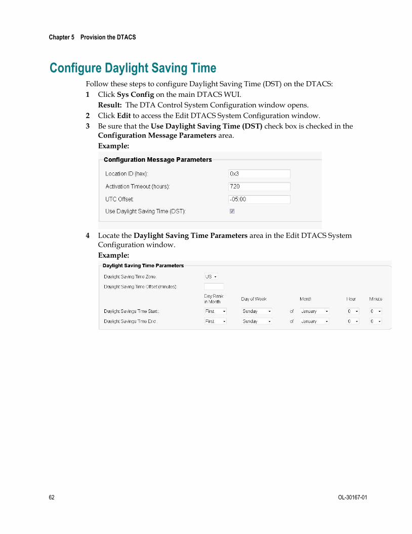
Chapter 5 Provision the DTACS
62 OL-30167-01
Configure Daylight Saving Time Follow these steps to configure Daylight Saving Time (DST) on the DTACS:
1 Click Sys Config on the main DTACS WUI.
Result: The DTA Control System Configuration window opens.
2 Click Edit to access the Edit DTACS System Configuration window.
3 Be sure that the Use Daylight Saving Time (DST) check box is checked in the Configuration Message Parameters area.
Example:
4 Locate the Daylight Saving Time Parameters area in the Edit DTACS System
Configuration window.
Example:

Configure Daylight Saving Time
OL-30167-01 63
5 Enter the settings for the DST rules that apply to your location. The following table lists descriptions for the DST settings.
Field Description
Daylight Saving Time Zone
The name of the daylight saving time zone currently in use.
Daylight Saving Time Offset (minutes)
The time shift (in minutes) relative to standard time.
Example: If daylight saving time is one hour ahead, you would enter 60 in this field. When a 0 (zero) is entered in this field, it indicates that the associated DST rule is to be ignored and not applied to the associated DST Zone ID.
This range is a whole number from -1430 to 1439.
Daylight Saving Time Start
Day Rank in Month The day of the month that the DST rule becomes effective.
Example: The first, second, third, fourth, or last Sunday of the month.
Day of Week The day of the week that the DST rule becomes effective.
Month The month the DST rule becomes effective.
Hour The hour the DST rule becomes effective, expressed in 24-hour time so that there is no need for a.m., p.m., or any other units of measure. Select any integer from 0 to 23.
Minute The number of minutes after the Start Hour that the DST rule becomes effective. This value is expressed in 24-hour time so that there is no need for a.m., p.m., or any other units of measure. Select any integer from 0 to 59.
Daylight Savings Time End
Day Rank in Month The day of the month that the DST rule ends.
Example: The first, second, third, fourth, or last Sunday of the month.
Day of Week The day of the week that the DST rule ends.
Month The month the DST rule ends.
Hour The hour the DST rule ends, expressed in 24-hour time so that there is no need for a.m., p.m., or any other units of measure. Select any integer from 0 to 23.
Minute The number of minutes after the End Hour that the DST rule ends. This value is expressed in 24-hour time so that there is no need for a.m., p.m., or any other units of measure. Select any integer from 0 to 59.
6 Click Save to save your settings.

Chapter 5 Provision the DTACS
64 OL-30167-01
Manage Virtual Channel Tables The DTA Control System's web-based user interface provides a way to manage Virtual Channel Tables (VCTs). The DTACS user interface allows you to manage the association of packages to VCTs. You can use this user interface to view, edit, add, and delete VCTs.
Add a New VCT
Follow these steps to add a new VCT.
Note: When you create a new VCT, any sources associated with packages that are included in the BSG channel map are automatically added to the associated VCT. However, if you edit the VCT later to assign new packages, then the sources contained in those packages are not automatically added to the VCT. You must add those sources separately.
1 From the Digital Transport Adaptor Control System main WUI, click VCT
Mapping in the Network Elements section.
Result: The VCT Mapping window opens.
Note: The VCT Mapping window allows you to manage VCTs. The DTAs use the VCT ID to retrieve their associated SI data among other sets of data that might be available. You can use this window to view, add, edit, and delete VCTs.

Manage Virtual Channel Tables
OL-30167-01 65
2 Click Add.
Result: The Add VCT Mapping window opens.
3 In the VCT Name field, type the name of the new VCT that you want to add.
4 In the VCT Id (hex) field, type the ID of the new VCT in hexadecimal format.
5 Click Add Package Set.
Result: The Add VCT Packages window opens.

Chapter 5 Provision the DTACS
66 OL-30167-01
6 In the Package Set Description field, enter the name of the package set.
Note: Package sets are unique groups of packages available to specific VCTs. You can have as many as 10 package sets for each VCT in your system.
7 Select a package that you want to assign to the VCT from the Available
Package(s) list, and then click Add.
Result: The package moves from the Available Package(s) column and into the Selected Package(s) column.
Example: Your window should look similar to the following example at this point.
8 Repeat Step 7 as often as necessary to add packages to the new VCT.
9 Click Add (at the bottom of the window).
Result: The Package set [Pkg_name] created successfully message appears.

Manage Virtual Channel Tables
OL-30167-01 67
10 Click OK on the message.
Note: The Add VCT Mapping window will update with the new package data after you close the window.
11 Click Save to save the changes to this VCT and then close the Add VCT Mapping
window.
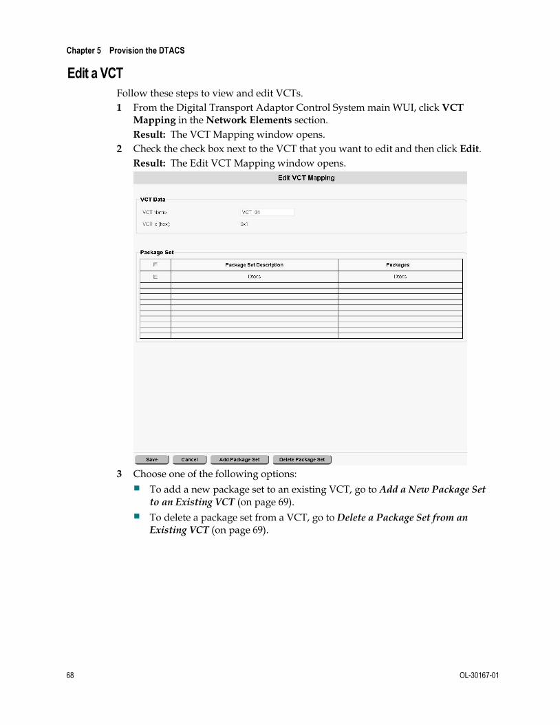
Chapter 5 Provision the DTACS
68 OL-30167-01
Edit a VCT
Follow these steps to view and edit VCTs.
1 From the Digital Transport Adaptor Control System main WUI, click VCT
Mapping in the Network Elements section.
Result: The VCT Mapping window opens.
2 Check the check box next to the VCT that you want to edit and then click Edit.
Result: The Edit VCT Mapping window opens.
3 Choose one of the following options:
To add a new package set to an existing VCT, go to Add a New Package Set to an Existing VCT (on page 69).
To delete a package set from a VCT, go to Delete a Package Set from an Existing VCT (on page 69).

Manage Virtual Channel Tables
OL-30167-01 69
Add a New Package Set to an Existing VCT
1 To add a new package set to the VCT, click Add Package Set.
Result: The Add VCT Packages window opens.
2 In the Package Set Description field, enter the name of the package set.
3 Select a package set that you want to assign to the VCT from the Available Package(s) list, and then click Add.
Result: The package set moves from the Available Package(s) column and into the Selected Package(s) column.
4 Repeat Step 3 as often as necessary to add up to 10 packages to the VCT.
5 Click Add (at the bottom of the window).
Result: The Package set [Pkg_name] created successfully message appears.
6 Click OK in the message.
Result: The Add VCT Mapping window updates with the new package data.
Delete a Package Set from an Existing VCT
1 To delete a package set, click the check box next to the package that you want to delete, and then click Delete.
Result: A confirmation message appears.
2 Click OK in the confirmation message.
Result: The system deletes the package set from the VCT.

Chapter 5 Provision the DTACS
70 OL-30167-01
Delete a VCT
Follow these steps to delete a VCT.
Note: You cannot delete a VCT that is being used by any DTA.
1 From the Digital Transport Adaptor Control System main WUI, click VCT
Mapping in the Network Elements section.
Result: The VCT Mapping window opens.
2 Click the check box next to the VCT that you want to delete on the VCT Mapping
window.
Result: A check mark appears in the check box.
3 Click Delete.
Result: A confirmation message appears.
4 Click OK.
Result: A message appears indicating that the VCT was deleted successfully.

Provisioning a Broadcast Service Group
OL-30167-01 71
Provisioning a Broadcast Service Group Important: If you want to provision a BSG and have the 1C-MCLU feature enabled, see instead Provision the Broadcast Service Group for the 1C-MCLU Feature.
A Broadcast Service Group (BSG) is a group of QAM channels that service a subset of the DTA device population. A single QAM channel can be associated with a single BSG. This section contains the procedures necessary to provision a BSG.
Note: BSG provisioning is also known as QAM localization.
BSG Overview
Some sites do not have a single homogeneous RF downstream plant frequency plan. Consequently, sites with multiple frequency plans require a separate, unique set of SI data flows for each unique RF plan.
These RF plans are called downstream plant regions (DPR). These DPRs are referred to as a logical construct within the DTACS called broadcast service groups (BSGs). To support a video network with multiple DPRs, several constraints must be addressed.
Billing System: The billing system associates a rate code with a specific service package. The service package is passed to the DTACS, which uses the package to define a set of services (channel lineups) for DTA client devices. However, service packages and their associated channel lineup information as defined on the billing system are not aware of any anomalies that may exist in the plant that affect delivery of those services. Therefore, locating the DTA client devices within the video network for the purpose of supplying it with a valid set of services is necessary.
VCT ID: A video network with several different frequency plans (DPRs) needs to reuse the same VCT ID (authorization code) for each of these DPRs. However, the channel maps associated with a redundant VCT ID (which is used by more than one DPR) may have differing content.
QAMs: For DTA client devices to located services on QAMs, all QAM carriers within a DPR must be associated with a single BSG. This means that no QAM RF channels are shared between two different BSGs. ("BSG straddle" is when a QAM carrier illuminates two BSGs. This is strictly forbidden.) All QAMs involved in delivering content to DTA client devices are assumed to be localized at the edge of the network.

Chapter 5 Provision the DTACS
72 OL-30167-01
Add a BSG
Follow these instructions to add a BSG to the DTACS:
1 From the Digital Transport Adaptor Control System main WUI, in the Network
Elements section, click BSG Management.
Result: The BSG Management window opens.

Provisioning a Broadcast Service Group
OL-30167-01 73
2 Click Add.
Result: The Add BSG window opens.
3 Follow these instructions to configure the fields on the Add BSG window:
a In the BSG Name field, type the name of the new BSG.
b In the Channel Map Name field, choose the name of the channel map associated with this BSG.
c In the Hub ID field, choose the name of the hub associated with this BSG.
Note: A Hub ID of 0 (zero) represents the hub of the default channel map.
d Choose a QAM in the Available Qams list and click Add to add that QAM to the Selected Qams list.
e Choose an RF port in the Available Ports list and click Add to add that port to the Selected Ports list.
Note: Available ports will be listed in the WUI once you select the QAMs in the Selected Qams list.
4 Click Save. The BSG details saved successfully message appears.

Chapter 5 Provision the DTACS
74 OL-30167-01
Associate Sources With a BSG
After adding your BSG(s), follow these instructions to associate sources with the BSG:
Note: The first time you open this WUI, package sources associated with the VCT will move to Selected Source(s) automatically.
1 On the Digital Transport Adaptor Control System main WUI, click VCT Source
Management (in the Network Elements section).
Result: The VCT Source Management window opens.
2 In the BSG Name field, select the BSG that you want to associate with a VCT.
3 In the VCT Name field, select the VCT to which you are adding a source.
4 Select a source in the Available Sources list and click Add to add that source to the Selected Sources list.
5 Click Save.
Note: The first time you open the BSG/VCT mapping WUI, the sources part of the packages associated with the VCT are moved to Selected Sources automatically.

Setting Up IP Streams
OL-30167-01 75
Setting Up IP Streams
Add IP Streams
Follow these steps to add IP Streams:
1 From the Digital Transport Adaptor Control System main WUI, click IP Stream
Management (in the Network Elements section).
Result: The IP Stream Management window opens.

Chapter 5 Provision the DTACS
76 OL-30167-01
2 Click either Add SI Stream or Add AMM Stream, depending upon which type of stream that you want to add.
Notes:
SI Stream refers to a System Information Message stream.
AMM Stream refers to a Authorization Management Message stream.
All of the AMM data messages are sent to every DTA. Therefore, you can only add one AMM stream.
Example: For this example, we will add an SI stream.
Result: The Add Stream window opens.
3 Follow these instructions to configure your IP stream.
a Notice that the Stream Type field is filled in and cannot be edited. This is based upon the stream type that you selected to add.
b In the Destination IP Address field, type the unique IP address associated with this stream.
c In the Destination IP Port field, type the UDP port associated with this stream.
d In the Data Rate (bps) field, enter the data rate, in bits per second, that is to be transmitted when using this stream.

Setting Up IP Streams
OL-30167-01 77
e Notice that the Packet ID field contains a predefined packet identifier (PID) that cannot be edited.
Note: The following values should be displayed:
– For SI — The PID is configured on the system as 0x1FFC. This cannot be edited.
– For AMM — The PID is configured on the System Configuration (Sys Conf) WUI and cannot be edited on this window.
f From the BSG Name list (applicable to SI streams, only), choose the BSG name associated with this SI stream.
4 Click Save.
Results:
The IP Stream created successfully message appears.
The IP Stream Management window reappears.
Query IP Streams
Follow these steps to select and query IP streams:
1 From the Digital Transport Adaptor Control System main WUI, click IP Stream
Management (in the Network Elements section).
Result: The IP Stream Management window opens.

Chapter 5 Provision the DTACS
78 OL-30167-01
2 From the Query Streams Stream Type list, choose the types of IP streams that you want to view. You can view all streams together, or you can choose to view only SI streams or only AMM streams.
3 Click Show to view the IP Streams List.
Notes:
The example in Step 2 shows all streams (SI and AMM).
You cannot change the data on this page. If you want to change IP stream data, you must click Edit.
Edit an IP Stream
Follow these steps to edit a stream information:
1 From the Digital Transport Adaptor Control System main WUI, click IP Stream
Management (in the Network Elements section).
Result: The IP Stream Management window opens.
2 From the Query Streams Stream Type list, choose the types of IP streams that
you want to view. You can view all streams together, or you can choose to view only SI streams or only AMM streams.
3 Click Show to view the IP Streams List.
4 Click the check box next to the stream that you want to edit.

Setting Up IP Streams
OL-30167-01 79
5 Click Edit.
Result: The Edit Stream window opens.
6 Enter whatever new data is required and then click Save.
Results:
The IP Stream updated successfully message appears.
The IP Stream Management window reappears.

Chapter 5 Provision the DTACS
80 OL-30167-01
Delete an IP Stream
Follow these instructions to delete an IP stream:
1 From the Digital Transport Adaptor Control System main WUI, click IP Stream
Management (in the Network Elements section).
Result: The IP Stream Management window opens.
2 From the Query Streams Stream Type list, choose the types of IP streams that
you want to view. You can view all streams together, or you can choose to view only SI streams or only AMM streams.
3 Click Show to view the IP Streams List.
4 Click the check box next to the Stream Type that you want to delete.
5 Click Delete.
Result: A confirmation message appears.
6 Click OK to delete the stream. A success message appears.
Edit User-Defined PID Routes
OL-30167-01 81
Edit User-Defined PID Routes There may be situations where you need to provision data sources for PID Routes (passthru PIDs) for PSIP, EAS, and other data, rather than using TSRs to pass the data through the entire transport stream.
Using passthru PID routes allows the data to flow through the QAM on carriers that contain DTA-related content. When you provision passthru PID routes for BSG-associated QAM carriers with active content, the DTACS sets up additional PID routes (AMM, SI/CVT with user-defined PID route sources) on those QAM carriers.
In order to set up a passthru PID route, you must first create the PID route source and then add a PID to that route.
Manage User-Defined Source Types
The Manage User Defined Source Types page allows you to add, edit, and delete source types for PID routes.
Add a User-Defined Source Type
Follow these instructions to add a passthru PID definition to a user-defined source in the DTACS:
1 In the Network Elements section of the DTACS WUI, click PID Route
Management. The PID Route Management window opens.
2 Click User Defined PID Route.
3 Click Manage User Defined Source Types. The Manage User Defined Source Types window opens.
4 Click Add. The Manage User Defined Source Types window opens.
5 Type the Source Name in the space provided.
6 Type an Output PID.
Note: You can add multiple output PIDs to the user-defined source.
7 Click Save. The DTACS creates the PID definition for the source you selected.
Edit a User-Defined Source Type
Follow these instructions to edit a passthru PID definition for a user-defined source in the DTACS:
1 In the Network Elements section of the DTACS WUI, click PID Route
Management. The PID Route Management window opens.
2 Click User Defined PID Route.
3 Click Manage User Defined Source Types. The Manage User Defined Source Types window opens.
4 Click to select the source that you want to edit.
5 Click Edit. The Edit User Defined Source Types window opens.

Chapter 5 Provision the DTACS
82 OL-30167-01
6 Edit the Source Type and the Output PID as needed.
Note: Each user-defined source can have multiple output PIDs.
7 If you need to add another output PID, click Add and enter the PID in the space provided.
8 Click Save.
Delete a User-Defined Source Type
Follow these instructions to delete a passthru PID from a user-defined source:
1 In the Network Elements section of the DTACS WUI, click PID Route
Management. The PID Route Management window opens.
2 Click User Defined PID Route.
3 Click Manage User Defined Source PIDs. The Manage User Defined Source PIDs window opens.
4 Click to select the PID definition that you want to delete.
5 Click Delete. A confirmation message appears.
6 Click OK. The PID definition is removed from the user-defined source and from the DTACS.
EAS Source Configuration
For the EAS aggregation to be enabled at the GQAM, the QAM PSIP/EAS Aggregation feature must be enabled on the EC.
1 On the Administrative Console, click the EC tab.
2 Click the Network Element Provisioning tab.
3 Click EAS Source. The EAS Data Sources List window opens
4 Click Add to open the Add EAS Data Source window.
5 Enter the following values.
Source Name — A unique name that describes this data source
Data Rate (bps) — The data rate for the source, in bps. Valid values are from 0 - 1,000,000 bps.
Destination IP Address — The multicast IP address the QAM must join to receive the EAS messages
Destination UDP Port — A user-selected, available, and non-reserved port number (for example, 2002)

Edit User-Defined PID Routes
OL-30167-01 83
Unicast Source IP Addresses
– 1st Source IP Address — Required. The unicast IP address of the primary source of the multicast. This is only available if the Destination
IP Address is a multicast IP address.
– 2nd Source IP Address - Optional. The unicast IP address of the secondary source of the multicast. This is only available if the
Destination IP Address is a multicast IP address and when there is an IP address in the 1st Source IP Address field.
– 3rd Source IP Address - Optional. The unicast IP address of the tertiary source of the multicast. This is only available if the Destination IP Address is a multicast IP address and when there is an IP address in the 2nd Source IP Address field.
6 Click Save. The source is listed in the EAS Data Source List window.
7 Click QAM from the Network Element Provisioning tab.
8 On the Filter tab, select By Field: QAM Type and By Value: GQAM. This lists the GQAMs available in the system on the QAM List window.
9 Select the row containing the GQAM entry and click Edit. The Edit QAM window opens.
10 Click the PSIP/EAS tab.
11 Click (to enable) the check box for the EAS Source and select the EAS Source created in the EAS Sources window for the Data Source field.
12 Repeat Step 11 for the required GQAM ports on which the EAS source data should be configured.
13 Click Save. The QAM List window opens.

Chapter 5 Provision the DTACS
84 OL-30167-01
Create a User-Defined PID Route Source
Follow these instructions to add a user-defined PID route source in the DTACS.
1 From the Digital Transport Adaptor Control System main WUI, click PID Route
Management (in the Network Elements section).
Result: The PID Route Management window opens, listing the PID routes available to the DTACS.

Edit User-Defined PID Routes
OL-30167-01 85
2 Click the User Defined PID Route tab.
Result: The PID Route Management window updates to list all of the user-defined PID routes.

Chapter 5 Provision the DTACS
86 OL-30167-01
3 Click Add.
Result: The Add User Defined PID Route Source window opens.
4 Follow these instructions to configure the fields on the Add User Defined PID
Route Source window:
a In the Source Type field, select the appropriate source type.
b In the Source Name field, type the unique name of the source you are adding. This is an alphanumeric field.
c In the Data Rate (bps) field, type the data rate for the data being carried by the PIDs (in bps).
Note: Typically, this data rate is somewhere around 200,000 bps for the combined PSIP and EAS PIDs (100,000 bps for each).
d In the Destination IP Address field, type the multicast IP address the QAM should join to get the PIDs.
Notes:
– If you are using the PID for PSIP, this is the multicast address of the video feed.
– If you are using the PID for EAS, this is the EAS multicast address.

Edit User-Defined PID Routes
OL-30167-01 87
e In the Destination UDP Port field, type the destination UDP port for the source (from 1 to 65535).
Note: This is only required if the Destination IP address is a unicast address, rather than a multicast address.
f In the Available Qams list, select the appropriate QAM and click Add to move the QAM to the Selected Qams list.
g In the Available Ports list, select a port and click Add to move the port to the Selected Ports list.
h In the 1st Source IP Address field, type the first multicast IP address for the source, if applicable.
5 Click Save. A message indicating successful execution appears.
Edit a User-Defined PID Route Source
Follow these instructions to edit a user-defined PID route source in the DTACS:
1 From the Digital Transport Adaptor Control System main WUI, click PID Route
Management (in the Network Elements section).
Result: The PID Route Management window opens, listing the PID routes available to the DTACS.

Chapter 5 Provision the DTACS
88 OL-30167-01
2 Click the User Defined PID Route tab.
Result: The PID Route Management window updates to list all of the user-defined PID routes.

Edit User-Defined PID Routes
OL-30167-01 89
3 Select the source that you want to edit, and click Edit.
Result: The Edit User Defined PID Route Source window opens.
4 Edit whatever fields are appropriate. refer to Create a User-Defined PID Route
Source (on page 84) for information on the various fields.
5 Click Save when you are finished. A message indicating successful execution appears.

Chapter 5 Provision the DTACS
90 OL-30167-01
Delete a User-Defined PID Route Source
Follow these instructions to delete a user-defined PID route source in the DTACS:
1 From the Digital Transport Adaptor Control System main WUI, click PID Route
Management (in the Network Elements section).
Result: The PID Route Management window opens, listing the PID routes available to the DTACS.

Edit User-Defined PID Routes
OL-30167-01 91
2 Click the User Defined PID Route tab.
Result: The PID Route Management window updates to list all of the user-defined PID routes.
3 Click the check box next to the PID route source that you want to delete.
4 Click Delete.
Result: A confirmation message appears.
5 Click OK in the confirmation message. A message indicating successful execution appears.

Chapter 5 Provision the DTACS
92 OL-30167-01
Manage DTA Types The DTA Type allows you to manage the DTA types in your system.
View DTA Types
To view DTA types, in the Common Download section of the DTACS Provisioning main window, click DTA Type. The DTA Type window opens, listing the available DTA types in the DTACS.

Manage DTA Types
OL-30167-01 93
Add a DTA Type
Follow these instructions to add a DTA Type in the DTACS:
1 In the Common Download section of the DTACS Provisioning main window, click DTA Type. The DTA Type window opens, listing the available DTA types in the DTACS.

Chapter 5 Provision the DTACS
94 OL-30167-01
2 Click Add. The Add DTA Type window opens.
3 Use this information to complete the fields on the Add DTA Type window:
Model Name — Type the model name of the DTA type.
Vendor ID (hex) — Type the hexadecimal number associated with the vendor in the :0xAABB format.
Hardware ID (hex) — Type the hexadecimal number associated with that vendor's hardware ID in the :0xAABB format.
Edit a DTA Type
Follow these instructions to edit a DTA Type in the DTACS:
1 In the Common Download section of the DTACS Provisioning main window, click DTA Type. The DTA Type window opens, listing the available DTA types in the DTACS.
2 Select the DTA Type to be edited.

Manage DTA Types
OL-30167-01 95
3 Click Edit. The Edit DTA Type window opens.
Note: The only field that you can edit is the Model Name. To change any of the other parameters, you must delete and re-add the DTA type.
4 Edit the Model Name field appropriately.
5 Click Save.
Delete DTA Types
Follow these instructions to delete a DTA type in the DTACS:
Note: You cannot delete a DTA type that is associated with a CVT. You must remove the DTA type from the CVT before you can delete the DTA type.
1 In the Common Download section of the DTACS Provisioning main window, click DTA Type. The DTA Type window opens.
2 Select the DTA type that you want to delete.
3 Click Delete. A confirmation window opens.
4 Click OK.

Chapter 5 Provision the DTACS
96 OL-30167-01
Common Download
Configure the DTACS Source on the EC
Follow these instructions to set up a source on the EC for the DTACS carousel:
1 On the Administrative Console, click the EC tab.
2 Click the System Provisioning tab.
3 Click Source to open the Source List window.
4 Click New to open the New Source window.
5 In the Source Name field, type a name to identify the source.
Example: DTACS CDL Carousel
6 In the Source ID field, type a unique number to identify this source.
Notes:
You must use a number that is greater than 200 to identify this source.
Write down the source ID that you use. You will refer to it later.
7 Click Save.
8 Do you already have a GQAM configured to use with the DTACS common download?
If yes, go to Configure the DTACS GQAM for the Common Download (on page 96).
If no, add a DTACS GQAM from the EC.
Configure the DTACS GQAM for the Common Download
This procedure describes how to configure an existing DTACS GQAM for the common download.
Important: Before beginning this procedure, note these important steps:
Be sure that the GQAM has sufficient bandwidth available to modulate the DTA images to the DTAs, typically 1 to 2 Mbps.
The GQAM that you use or set up must use the GbE connection to communicate to the headend.
This procedure is for an existing GQAM that can be used for the DTACS common download feature. If you need to add a GQAM for this purpose, refer to the EC online help.
Follow these instructions to configure the DTACS GQAM for common download:
1 On the Administrative Console, click the EC tab.
2 Click the Network Element Provisioning tab.
3 Click GQAM. The GQAM List window opens.

Common Download
OL-30167-01 97
4 Select the GQAM that you are configuring and click Edit.
5 Select an output port on the GQAM that has sufficient bandwidth available for modulating the DTA images to the DTAs (typically, 1 to 2 Mbps).
6 Write down this port number and frequency for later use.
Add a Multicast Source Definition to the EC
Follow these instructions to add a source definition to the EC:
1 On the Administrative Console, click the EC tab.
2 Click the System Provisioning tab.
3 Click Source. The Source List window opens.
4 Select the row containing the service source you need to define and then select Source Definitions. The Source Definition List window opens for the source you selected.
5 Click Add to open the Set Up Definition window.
6 Select the Digital Source Definition.
7 Enter the Session ID for this session.
Notes:
The left part of the Session ID is the session MAC address. Type 12 zeros (the system inputs the colons for you).
The right part of the Session ID is the source ID you used when you added the DTACS.
8 If you need to specify when this source will become active, select Specify
effective date and time to enter that information. If left unselected (unchecked), the source will become available immediately.
9 Select the Multicast through a GQAM option.
10 Configure the Multicast Digital Session Definition window.
Session ID — The Session ID field has two parts, the left Session ID and the right Session ID.
– Left Session ID — The session MAC address. Type 12 zeros (the system inputs the colons for you).
– Right Session ID — The source ID you used when you added the content source.
Bandwidth (Mbps) — The bandwidth available to this source. Typically, this will be 1 to 2 Mbps, defined by the limits of the DTA or by the bandwidth available on the GQAM.
QAM Name — Select the GQAM you configured for DTACS common download.
Output Carrier — The GQAM output port you defined for the DTACS common download.
Program Number — The MPEG program number.

Chapter 5 Provision the DTACS
98 OL-30167-01
Source IP Address 1 — The IP address of the DTACS interface that the dataPump (DTACS carousel) uses to stream the DTA images.
Source IP Address 2 — The second IP address of the DTACS interface that the dataPump (DTACS carousel) uses to stream the DTA images. If not used, leave empty.
Source IP Address 3 — The third IP address of the DTACS interface that the dataPump (DTACS carousel) uses to stream the DTA images, if used. If not used, leave empty.
Input Destination Multicast IP Address — The unique (dedicated) multicast IP address that the dataPump (DTACS carousel) uses to send the image stream. This multicast IP address is the address that the GQAM should join via the headend router to receive the image stream.
Important: For this field, use a unique IP address; do not use the other DTACS multicast IP addresses (that support PID routes, SI, CVT, or AMM).
UDP Port — A user-selected, available, and non-reserved port number (for example, 2002).
11 Click Save. The source is listed in the Source Definition List window and should display as active.
Sync the Database
Whenever you make changes to the EC that also affect the DTACS, you need to synchronize the two databases so that the changes are reflected at the DTACS. Use these instructions to synchronize the databases:
1 In the DTACS WUI, click Sys Config.
2 Click the DB Sync tab.
3 Click DB Sync to initiate the DTACS database synchronization process.
Note: The table refreshes automatically every 3 seconds.
4 Check the Status field in the DB Sync Status History table in the database. If the status shows In Progress, wait a few seconds for the status to update.
Create the Images Directory on the DTACS
You now need to create the images directory on the DTACS so that you can store DTA code files (known as images) on the DTACS.
1 Log in to the DTACS as the root user.
2 Type the following command and press Enter: cd /dvs/dtacs
3 Type the following command and press Enter to create the images directory in the /dvs/dtacs directory: mkdir images
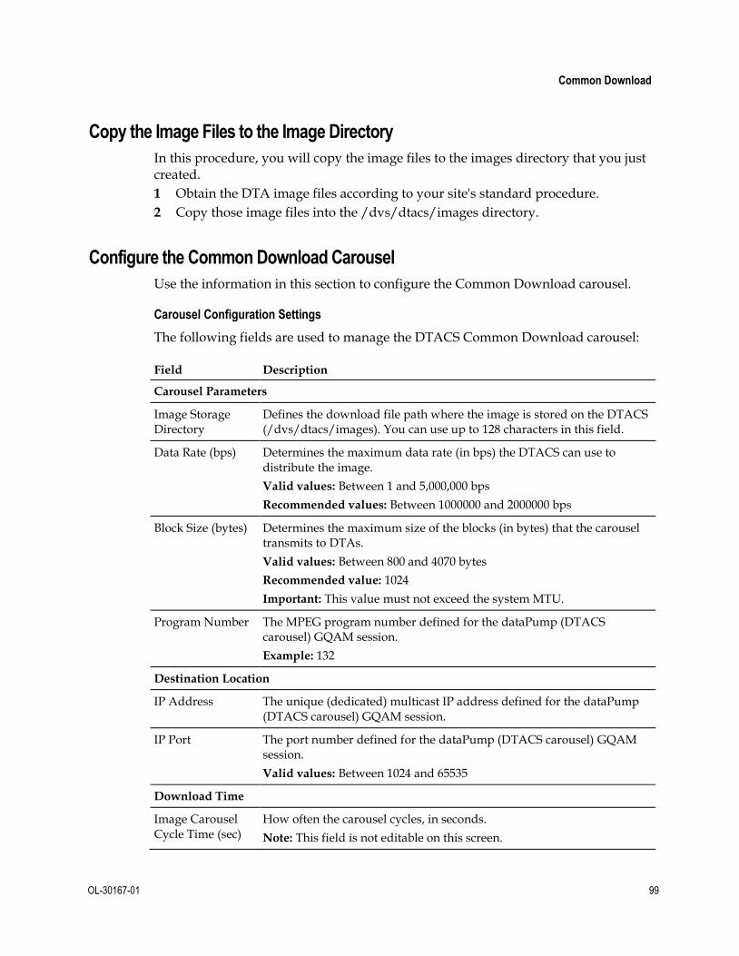
Common Download
OL-30167-01 99
Copy the Image Files to the Image Directory
In this procedure, you will copy the image files to the images directory that you just created.
1 Obtain the DTA image files according to your site's standard procedure.
2 Copy those image files into the /dvs/dtacs/images directory.
Configure the Common Download Carousel
Use the information in this section to configure the Common Download carousel.
Carousel Configuration Settings
The following fields are used to manage the DTACS Common Download carousel:
Field Description
Carousel Parameters
Image Storage Directory
Defines the download file path where the image is stored on the DTACS (/dvs/dtacs/images). You can use up to 128 characters in this field.
Data Rate (bps) Determines the maximum data rate (in bps) the DTACS can use to distribute the image.
Valid values: Between 1 and 5,000,000 bps
Recommended values: Between 1000000 and 2000000 bps
Block Size (bytes) Determines the maximum size of the blocks (in bytes) that the carousel transmits to DTAs.
Valid values: Between 800 and 4070 bytes
Recommended value: 1024
Important: This value must not exceed the system MTU.
Program Number The MPEG program number defined for the dataPump (DTACS carousel) GQAM session.
Example: 132
Destination Location
IP Address The unique (dedicated) multicast IP address defined for the dataPump (DTACS carousel) GQAM session.
IP Port The port number defined for the dataPump (DTACS carousel) GQAM session.
Valid values: Between 1024 and 65535
Download Time
Image Carousel Cycle Time (sec)
How often the carousel cycles, in seconds.
Note: This field is not editable on this screen.

Chapter 5 Provision the DTACS
100 OL-30167-01
View the Common Download Carousel Settings
Follow these instructions to view the common download carousel settings on the DTACS:
1 In the Common Download section of the DTACS WUI, click Image Management. The Image Management window opens.
2 Click Carousel Configuration. The Carousel Configuration window opens, listing the configuration parameters for the carousel.
Configuring the Common Download Carousel
Follow these instructions to configure the common download carousel of the DTACS:
1 In the Common Download section of the DTACS WUI, click Image
Management. The Image Management window opens.
2 Click Carousel Configuration. The Carousel Configuration window opens.
3 Click Edit. The Edit Carousel Configuration window opens.
4 Edit information as described in Carousel Configuration Settings.
5 Click Save.
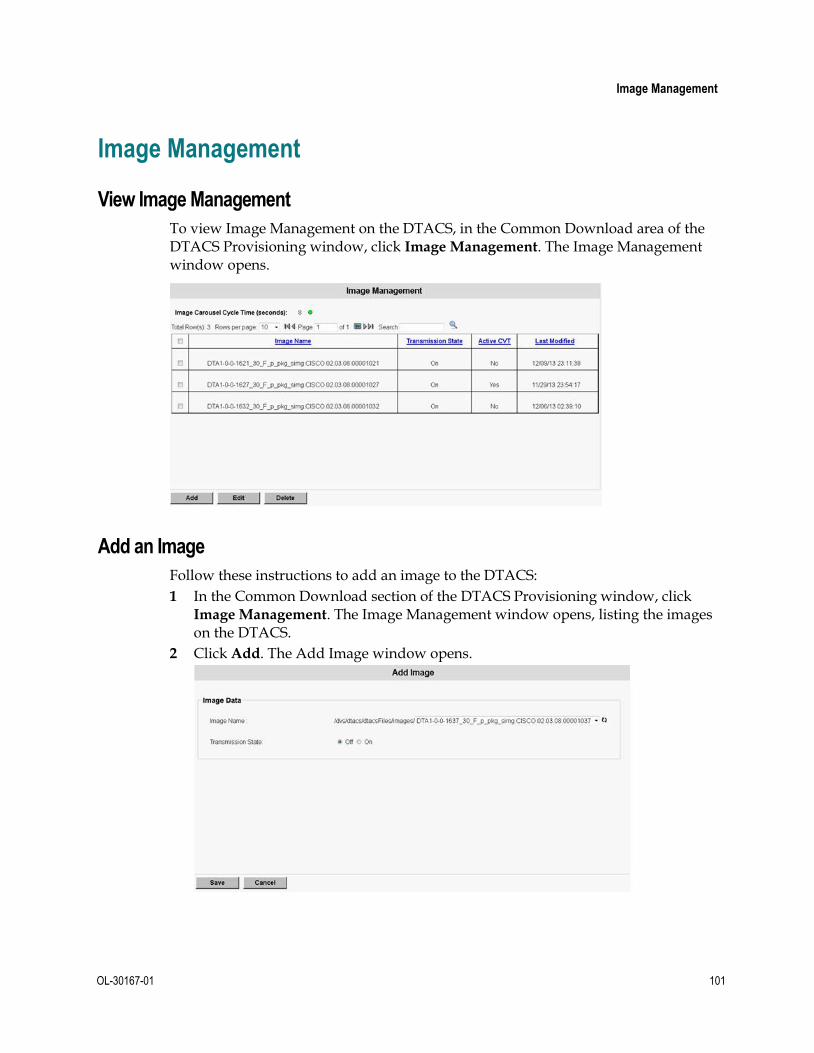
Image Management
OL-30167-01 101
Image Management
View Image Management
To view Image Management on the DTACS, in the Common Download area of the DTACS Provisioning window, click Image Management. The Image Management window opens.
Add an Image
Follow these instructions to add an image to the DTACS:
1 In the Common Download section of the DTACS Provisioning window, click Image Management. The Image Management window opens, listing the images on the DTACS.
2 Click Add. The Add Image window opens.

Chapter 5 Provision the DTACS
102 OL-30167-01
3 Use this information to complete the fields in the Add Image window:
Image Name — Choose the Image Name from the drop-down list.
Transmission State — Click the appropriate Transmission State, either Off or On.
Edit an Image
Follow these instructions to edit a DTACS image:
1 In the Common Download area of the DTACS Provisioning window, click Image
Management. The Image Management window opens, listing the available Images on the DTACS.
2 Select an Image Name to be edited.
3 Click Edit. The Edit Image window opens.
Note: The only field that you can edit is the Transmission State. To change any of the other parameters, you must delete and re-add an Image.
4 Edit the Transmission State field appropriately.
5 Click Save.
Delete an Image
Follow these instructions to delete an Image on the DTACS:
Note: You may receive the following warning message if the Image has a CVT association:
Warning: Deleting Image with transmission state ON and Active CVT might
cause downloads to fail and DTA(s) might stop delivering video. Are you sure
you want to continue?
1 In the Common Download area of the DTACS Provisioning window, click Image
Management. The Image Management window opens.
2 Select an Image Name that you want to delete.
3 Click Delete. A confirmation window opens.
4 Click OK.

Manage CVTs
OL-30167-01 103
Manage CVTs
Configure the CVT Repeat Rate
When CVT associations are created, CVTs are sent to all DTAs by the DTACS in repeated intervals. In the DTACS implementation, the CVT repeat rate is set to 60 seconds, as a default. This repeat rate is specified in the cvtMgr.cfg file.
If the cvtMgr.cfg file is not already present in the /dvs/dtacs/etc file, copy the cvtMgr.cfg.sample file from /dvs/dtacs/etc as cvtMgr.cfg. Then, edit the file.
CVT_REPEAT_RATE=60
Note: To cause your change to the CVT_REPEAT_RATE parameter, bounce the dtacsCvtMgr process.
Add a CVT
Follow these instructions to add a CVT to the DTACS:
1 In the Common Download section of the DTACS Provisioning main screen, click CVT Management. The CVT Management window opens.

Chapter 5 Provision the DTACS
104 OL-30167-01
2 Click Add. The Add CVT window opens.
3 Follow these instructions to configure the Add CVT window:
a In the CVT Name field, enter the unique name of the CVT entry.
Note: You cannot edit this field later, once it has been saved.
b The Transmission State field determines whether this CVT is being transmitted. It is On if the CVT is active for any CVT association.
Note: This field cannot be edited during an add or edit operation.
c Click the down-arrow of the DTA Type field and select the appropriate DTA type for the CVT you are adding.
Note: You cannot edit this field later, once it has been saved.
d In the Carousel type field. select either Local to use a loaded image, or select Remote to use another type of image.
e In the Location Type field, which specifies the location of the download code, select one of the following:
– Source ID
– Frequency, Packet ID, Modulation Type
– Frequency, MPEG Program Number, Modulation Type
Note: How you configure the rest of this window depends upon the Location Type you specified.
f In the Source ID field, enter the source of the program, if relevant.
g In the Frequency field, enter the frequency (in MHz) used to transmit the CVT to the DTAs, if relevant.
Note: Valid values are in 0.25 MHz intervals.
h In the MPEG Program Number field, enter the MPEG program number that corresponds to this CVT, if relevant.

Manage CVTs
OL-30167-01 105
i In the Packet ID field, enter the PID that corresponds to this CVT, if relevant.
j The Modulation Type field specifies the type of modulation used for this CVT, if relevant. Select either QAM 64 or QAM 256.
4 Click Save. A message indicating successful execution appears.
Edit a CVT
Follow these instructions to edit an existing CVT:
1 In the Common Download section of the DTACS Provisioning main screen, click CVT Management. The CVT Management window opens.
2 Click the checkbox to the left of the CVT that you want to edit, and then click Edit. The Edit CVT window opens showing the data with which that CVT was configured.
3 Edit the CVT appropriately and then click Save. A message indicating successful
execution appears.
Delete a CVT
Follow these instructions to delete a CVT from the DTACS:
1 In the Common Download area of the DTACS Provisioning main screen, click CVT Management. The CVT Management window opens.
2 Click the check box to the left of the CVT that you want to delete, and then click Delete.
Result: A confirmation message appears.
3 Click OK to delete the CVT. A message indicating successful execution appears.

Chapter 5 Provision the DTACS
106 OL-30167-01
Manage Download Groups
View Download Groups
To view Download Groups on the DTACS, in the Common Download area of the DTACS Provisioning main window, click Download Groups. The Download Groups window opens.

Manage Download Groups
OL-30167-01 107
Add a Download Group
Follow these instructions to add a download group in the DTACS:
Note: You can have as many as 15 download groups.
1 In the Common Download area of the DTACS Provisioning main window, click Download Groups. The Download Groups window opens.

Chapter 5 Provision the DTACS
108 OL-30167-01
2 Click Add. The Add Download Group window opens.
3 Complete the following fields on the Add Download Group window:
Group ID — Choose the group ID from the drop-down list. You can have as many as 15 download groups in the DTACS.
Group Description — Type a description for the group.
Show in CVT Association List UI — Determines whether this group is listed in the CVT Association user interface. Select one of the following options:
– Off - (default) Do not show this group in the CVT Association user interface list.
– On - Show this group in the CVT Association user interface list.
Edit a Download Group
Follow these instructions to edit a download group in the DTACS:
1 In the Common Download area of the DTACS Provisioning main window, click Download Groups. The Download Groups window opens.
2 Select the download group that you want to edit.

Manage Download Groups
OL-30167-01 109
3 Click Edit. The Edit Download Group window opens.
Note: You cannot edit the Group ID field. To change the Group ID, you must delete and re-add the group.
4 Edit the appropriate field(s).
5 Click Save.
Delete Download Groups
Follow these instructions to delete a download group in the DTACS:
1 In the Common Download area of the DTACS Provisioning main window, click Download Groups. The Download Groups window opens.
2 Choose the group that you want to delete.
3 Click Delete. A confirmation window opens.
4 Click OK.

Chapter 5 Provision the DTACS
110 OL-30167-01
Associate CVTs The CVT Association allows you to associate CVTs provisioned already for various models to every BSG and DTA type pair. A CVT becomes active only when you create the association with a Transmission State of Non-Group-CVT or CVT-by-
Group.
View CVT Associations
Follow these instructions to view CVT associations in the DTACS:
1 In the Common Download area of the DTACS Provisioning main window, click CVT Association. The CVT Association window opens.
Note: The green color indicates the CVTs that are being transmitted. The red color indicates the ones that are not being transmitted. The transmission state of the association determines the color of the CVTs shown in this list
2 Choose the BSG Name from the list. The CVTs associated with that BSG are listed in the table.

Associate CVTs
OL-30167-01 111
Add a CVT Association
Follow these instructions to add a CVT association in the DTACS:
1 In the Common Download area of the DTACS Provisioning main window, click CVT Association. The CVT Association window opens.

Chapter 5 Provision the DTACS
112 OL-30167-01
2 Click Add. The Add CVT Association window opens.
3 Use the following information to configure the fields on the Add CVT
Association window:
BSG Name — Choose the name of the BSG associated with this CVT from the drop-down list.
DTA Type — Choose the DTA Type associated with this CVT from the drop-down list.
Note: The CVT association will be created for the BSG - DTA type pair.
Transmission State — Select the transmission state for this CVT.
– No-CVT — The CVT association is created, but the CVTs are not sent to the BSG. CVT selection is not mandatory for groups and non-groups.
– Non-Group-CVT — The CVT association is created and the CVT is sent without a group descriptor to the BSG. CVT selection is mandatory for non-groups, not mandatory for groups.
– CVT-by-Group — The CVT association is created and the CVTs are transmitted to the BSG with group descriptors, containing a Group ID. Each CVT corresponds to a group. CVT selection is mandatory for groups, not mandatory for non-groups.
Group ID — Displays the group ID.
Group Description — Displays the description of the group.

Associate CVTs
OL-30167-01 113
CVT Name (Image Transmission) — Displays all available CVTs for the selected DTA Type. Select the CVT Name associated with this group from the drop-down list.
Note: The Add CVT Association window supports multiple operations to be performed in this window. Hence, all fields are editable. The WUI control does not take the user back to the CVT Association main window after saving the additions. Click Cancel to return to the CVT Association main window.
Edit a CVT Association
Follow these instructions to edit a CVT association in the DTACS:
1 In the Common Download area of the DTACS Provisioning main window, click CVT Association. The CVT Association window opens.
2 Select the CVT Association that you want to edit.
3 Click Edit. The Edit CVT Association window opens.
4 Edit whatever fields need to be edited.
5 Click Save.
Note: The Edit CVT Association window supports multiple operations to be performed in this window. Hence, all fields are editable. The WUI control does not take the user back to the CVT Association main window after saving the edits. Click Cancel to return to the CVT Association main window.

Chapter 5 Provision the DTACS
114 OL-30167-01
Delete CVT Associations
Follow these instructions to delete a CVT association in the DTACS:
1 In the Common Download section of the DTACS Provisioning main window, click CVT Association. The CVT Association window opens.
2 Select the CVT Association that you want to delete.
3 Click Delete. A confirmation window opens.
4 Click OK. The CVT association is removed from the DTACS.

Configure Source-SCID Mapping
OL-30167-01 115
Configure Source-SCID Mapping You can identify channels available for viewing by a DTA by identifying sources on the Source - SCID Mapping window. The DTACS assigns unique Simple Channel IDs (SCIDs) to sources identified as DTACS sources.
The Source - SCID Mapping screen allows you to choose a source as a DTACS source from the available list of sources, to modify the SCC parameters of a source, and to delete a DTACS source.
Note: If the DLNA feature is enabled or disabled, the WUI needs to restarted by closing the existing browser and reopening it.
View Source-SCID Mappings 1 In the Service Packaging area of the DTACS Provisioning window, click Source
- SCID Mapping. The Source-SCID Mapping List window opens.
2 From the Filter list, choose the type of mapping that you want to view. The options are:
All
Source ID
Source Name
Source Type
SCID
SCC Mode
3 Click Show. The Source-SCID Mapping List window opens, displaying the mappings that you selected for both DLNA range and Standard range SCIDs.
Note: This example, with the DLNA feature enabled, shows All Sources with mapped SCIDs.

Chapter 5 Provision the DTACS
116 OL-30167-01
Add a Source - SCID Mapping 1 In the Service Packaging area of the DTACS main window, click Source - SCID
Mapping. The Source-SCID Mapping List window opens.
2 Click Add. The Add Source-SCID Mapping window opens.
Note: This example, with the DLNA feature enabled, shows the Sources that need to be mapped to SCIDs.
3 Select the Source(s) to which you want to map.
4 Select the SCC Mode for this mapping.
5 Select the DLNA Source check box for this mapping in DLNA range and un-check the DLNA Source for this mapping in Standard range.
6 Use the following information to complete your configuration:
Source Name — The name of the source in the mapping.
Source ID — The unique, numerical ID of the source.
Source Type — The type of source in the mapping.
Source Compression Type — The type of compression used on the source.
Digital Copy Rights — The rights of the source for subscriber copying.
Note: If there are no segments for the source, the Digital Copy Rights is always set to Copy Never.
SCID — The Simple Channel ID of the source in the mapping.

Configure Source-SCID Mapping
OL-30167-01 117
SCC Mode — The SCC mode of the mapping. Choose one of the following options:
– Initialization: SCC is not enabled, and the service is allowed to be viewed by any DTA.
– Enable: Normal SCC operation. The SCID from the ACM must be set to 1
in the SCC AMM bitmap for the service to be allowed (either in the clear or encrypted).
– Preview: ACM processing is similar to Enabled mode, but the SCID of the service is ignored. This mode is recommended for Free Preview modes.
DLNA Source — The sources that have the DLNA Source enabled have the SCIDs generated in the DLNA range. The sources that have the DLNA Source disabled have the SCIDs generated in the Standard range.
7 Click Save.
Edit a Source - SCID Mapping 1 In the Service Packaging section of the DTACS main window, click Source -
SCID Mapping. The Source-SCID Mapping List window opens.
2 Click the drop-down list in the Filter section and choose the type of mapping that you want to view. The options are:
All
Source ID
Source Name
Source Type
SCID
SCC Mode
3 Click Show. The Source-SCID Mapping List window opens, displaying the mappings that you selected.
4 Select the mapping that you want to edit.
5 Click Edit. The Edit Source-SCID Mapping window opens.
6 Select the SCC Mode for this mapping.
7 Edit whatever fields need to be changed.
8 Click Save when you are finished.

Chapter 5 Provision the DTACS
118 OL-30167-01
Delete a Source - SCID Mapping 1 In the Service Packaging section of the DTACS main window, click Source -
SCID Mapping. The Source-SCID Mapping List window opens.
2 Click the Source-SCID Mapping List and choose the type of mapping that you want to view. The options are:
All
Source ID
Source Name
Source Type
SCID
SCC Mode
3 Click Show. The Source-SCID Mapping List window opens, displaying the mappings that you selected.
4 Select the mapping that you want to delete.
5 Click Delete. A confirmation window opens.
6 Click OK.

Manage Authorization Codes
OL-30167-01 119
Manage Authorization Codes Authorization codes manage authorizations on the DTACS. The information in this section allows you to create new authorization codes, to associate and disassociate sources to authorization codes, to delete authorization codes, and to associate a Group ID to an authorization code.
View Authorization Codes 1 In the Service Packaging area of the DTACS Provisioning window, click Auth
Code Management. The Auth Code List window opens.
2 Click the Auth Code List and choose the type of mapping that you want to view:
All or Auth Code Name.

Chapter 5 Provision the DTACS
120 OL-30167-01
3 Click Show. The Auth Code List window opens, displaying the authorization codes that you selected.
Example: The following example shows All Authorization Codes:
Add Authorization Codes 1 In the Service Packaging section of the DTACS Provisioning window, click Auth
Code Management. The Auth Code List window opens.
2 Click Add. The Add Auth Code window opens.

Manage Authorization Codes
OL-30167-01 121
3 Use the following information to configure the Add Auth Code window:
Auth Code Name — The unique, alphanumeric name of this authorization code.
Important:
– This name does not need to be a package name.
– This name can be same as the package name on the EC for any authorization code mapped to a Source/Group ID/HD Enabled.
– This name cannot be part of any package sets defined in the DTACS to identify VCTs.
– You can enter up to 20 alphanumeric characters in this field.
– This field is not editable.
Auth Code Description — A description of the authorization code. You can enter up to 64 alphanumeric characters in this field.
Auth Code Mapping — Select the type of mapping that this code uses.
– Source Mapping (default): This authorization code will map to sources. See the notes in the Auth Code Name field in regards to naming conventions associated with this option. Selecting this option enables the fields in the Source Association section.
– Group Mapping: This authorization code will map to a group. Selecting this option enables the field in the Group ID Association section.
– HD Enabled: This authorization code is high-definition video-enabled.
Note: This checkbox will be available for selection when at least one HD authorization code is available in the system.
Available Sources — Sources available in the DTACS for the authorization code. Select a source in the Available Sources list and click Add to add that source to the Associated Sources list.
Note: This section is only active if Source Mapping is selected in the Auth Code Mapping field.
Associated Sources — Sources assigned to this authorization code. Select a source in the Associated Sources list and click Remove to remove that source from the Associated Sources list.
Note: This section is only active if Source Mapping is selected in the Auth
Code Mapping field.
Group ID — Select the group associated with this authorization code.
Note: This field is only active if Group Mapping is selected in the Auth
Code Mapping field.
4 Does the source-mapped authorization code need to be synchronized with the packages on the EC?
If yes, go to the next step.
If no, you are finished with this procedure.

Chapter 5 Provision the DTACS
122 OL-30167-01
5 Click Sync Def Pkg to synchronize the authorization code with the package on the EC.
6 Click Save. A message indicating successful execution appears.
Edit Authorization Codes
Follow these instructions to edit an authorization code:
1 In the Service Packaging area of the DTACS Provisioning window, click Auth
Code Management. The Auth Code List window opens.
2 Click the drop-down list in the Filter section and choose the type of mapping that you want to view: All or Auth Code Name.
3 Click Show. The Auth Code List window opens, displaying the authorization codes you selected.
Example: The following example shows All Authorization Codes.
4 Select the authorization code that you want to edit.

Manage Authorization Codes
OL-30167-01 123
5 Click Edit. The Edit Auth Code window opens.
6 Edit the fields as appropriate.
Note: The Auth Code Name field is not editable. To change the name, you must delete and re-add the authorization code.
7 Does the source-mapped authorization code need to be synchronized with the packages on the EC?
If yes, go to the next step.
If no, you are finished with this procedure.
8 Click Sync Def Pkg to synchronize the authorization code with the package on the EC.
9 Click Save. A message indicating successful execution appears.

Chapter 5 Provision the DTACS
124 OL-30167-01
Delete Authorization Codes
Follow these instructions to delete an authorization code from the DTACS:
1 In the Service Packaging area of the DTACS Provisioning window, click Auth
Code Management. The Auth Code List window opens.
2 Click the drop-down list in the Filter section and choose the type of mapping that you want to view: All or Auth Code Name.
3 Click Show. The Auth Code List window opens, displaying the authorization codes that you selected.
4 Select the authorization code(s) that you want to delete.
5 Click Delete. A confirmation window opens.
6 Click OK. A message indicating successful execution appears.
Synchronize All Authorization Codes with EC Packages 1 In the Service Packaging area of the DTACS Provisioning window, click Auth
Code Management. The Auth Code List window opens.
2 Click the drop-down list in the Filter section and choose the type of mapping that you want to view: All or Auth Code Name.
3 Click Show. The Auth Code List window opens, displaying the authorization codes that you selected.
4 Select the Source Mapping Auth Code(s) that you want to synchronize.
5 Click Sync All.
Synchronize an Authorization Code with the EC Package
When you add or edit a source-mapped code (the Auth Code Mapping parameter is set to Source Mapping), follow this procedure if you need to synchronize the code with the EC package:
1 In the Service Packaging section of the DTACS Provisioning window, click Auth
Code Management. The Auth Code List window opens.
2 Click the drop-down list in the Filter section and choose the type of mapping you want to view: All or Auth Code Name.
3 Click Show. The Auth Code List window opens, displaying the authorization codes you selected.

Manage Authorization Codes
OL-30167-01 125
4 Click Edit. The Edit Auth Code window opens.
5 Click Sync Def Pkg to synchronize the authorization code with the package on
the EC.
6 Click Save.

Chapter 5 Provision the DTACS
126 OL-30167-01
Manage DTAs
View a DTA 1 From the Digital Transport Adaptor Control System main WUI, click DTA
Management (in the Home Elements section).
Result: The DTA Entry List window opens.
2 In the DTA Filter area, in the By Field field, select one of the criterion upon
which you can sort.
Notes:
Options are Unit Address, VCT ID, and Group ID.
For this example, we will filter upon VCT ID.
3 Select VCT ID and then type a valid VCT ID.
Example: 0x10

Manage DTAs
OL-30167-01 127
4 Click Show.
Result: The window updates to display the results of the filter action.
5 Select one of the buttons at the bottom of the page to continue setting up the
DTAs. Each function is covered in one of the following sections.

Chapter 5 Provision the DTACS
128 OL-30167-01
Add a DTA 1 From the Digital Transport Adaptor Control System main WUI, click DTA
Management (in the Home Elements section).
Result: The DTA Entry List window opens.

Manage DTAs
OL-30167-01 129
2 Click Add.
Results: The Add DTA Entry window opens.
3 Follow these instructions to configure the Add DTA Entry window:
a In the Unit Address field, type the MAC address of the DTA that you want to add.
b In the Activation State field, click either Off or On, depending upon whether the DTA is to be active or not.
c Click to select the HD Enable field if you want to enable high-definition video on this DTA.
Note: This field is only editable if at least one authorization code in the system is HD-enabled.
d In the VCT field, click the arrow and select the name of the VCT associated with the DTA that you are adding.
e Click the arrow to the right of the Group ID field to select the group to which the DTA you are adding will belong.
f In the Available AuthCodes field, select an authorization code and then click Add to move that authorization code to the Selected AuthCodes list.
Note: The authorization codes that are displayed are those codes that are mapped to sources and are not authorized to the DTA.
4 Click Save. A message indicating successful execution appears.

Chapter 5 Provision the DTACS
130 OL-30167-01
Edit a DTA
Follow these steps to edit a DTA:
1 From the Digital Transport Adaptor Control System main WUI, click DTA
Management (in the Home Elements section).
Result: The DTA Entry List window opens.
2 In the DTA Filter area, in the By Field field, select one of the criterion upon
which you can sort.
Notes:
Options are Unit Address, VCT ID, and Group ID.
For this example, we will filter upon VCT ID.
3 Select VCT ID and then type a valid VCT ID.
Example: 0x10

Manage DTAs
OL-30167-01 131
4 Click Show.
Result: The window updates to display the results of the filter action.
5 Click the check box of the DTA that you want to edit.

Chapter 5 Provision the DTACS
132 OL-30167-01
6 Click Edit.
Result: The Edit DTA Entry window opens.
7 Follow these instructions to update the appropriate fields on the Edit DTA Entry
window:
a In the Activation State field, click either Off or On, depending upon whether the DTA is to be active or not.
b Click to select the HD Enable field if you want to enable high-definition video on this DTA.
Note: This field is only editable if at least one authorization code in the system is HD-enabled.
c In the VCT field, select the name of the VCT associated with the DTA you are adding.
d Click the arrow to the right of the Group ID field to select the group to which the DTA you are adding will belong.
e In the Available AuthCodes field, select an authorization code and then click Add to move that authorization code to the Selected AuthCodes list.
Note: The authorization codes that are displayed are those codes that are mapped to sources and are not authorized to the DTA.
8 Click Save. A message indicating successful execution appears.

Manage DTAs
OL-30167-01 133
Delete a DTA 1 From the Digital Transport Adaptor Control System main WUI, click DTA
Management (in the Home Elements section).
Result: The DTA Entry List window opens.
2 In the DTA Filter area, in the By Field field, select one of the criterion upon
which you can sort.
Notes:
Options are Unit Address, VCT ID, and Group ID.
For this example, we will sort upon VCT ID.
3 Select VCT ID and then type a valid VCT ID.
Example: 0x10

Chapter 5 Provision the DTACS
134 OL-30167-01
4 Click Show.
Result: The window updates to display the results of the filter action.
5 Click the check box of the DTA or DTAs that you want to delete.
6 Click Delete.
Result: A confirmation message appears.
7 Click OK.
Result: The DTA or DTAs are removed from the DTACS and a message indicating successful execution appears.

Manage DTAs
OL-30167-01 135
Reset the NVM of a DTA 1 From the Digital Transport Adaptor Control System main WUI, click DTA
Management (in the Home Elements section).
Result: The DTA Entry List window opens.
2 In the DTA Filter area, in the By Field field, select one of the criterion upon
which you can sort.
Notes:
Options are Unit Address, VCT ID, and Group ID.
For this example, we will sort upon VCT ID.
3 Select VCT ID and then type a valid VCT ID.
Example: 0x10

Chapter 5 Provision the DTACS
136 OL-30167-01
4 Click Show.
Result: The window updates to display the results of the filter action.
5 Click the check box of the DTA or DTAs that you want to reset.
6 Click Reset NVM.
Result: A confirmation message appears.
7 Click OK.
Result: The DTACS resets the NVM and a message indicating successful execution appears.

Manage DTAs
OL-30167-01 137
Reboot a DTA 1 From the Digital Transport Adaptor Control System main WUI, click DTA
Management (in the Home Elements section).
Result: The DTA Entry List window opens.
2 In the DTA Filter area, in the By Field field, select one of the criterion upon
which you can sort.
Notes:
Options are Unit Address, VCT ID, and Group ID.
For this example, we will sort upon VCT ID.
3 Select VCT ID and then type a valid VCT ID.
Example: 0x10

Chapter 5 Provision the DTACS
138 OL-30167-01
4 Click Show.
Result: The window updates to display the results of the filter action.
5 Click the checkbox of the DTA or DTAs that you want to reboot.
6 Click Reboot.
Result: A confirmation message appears.
7 Click OK.
Result: The DTACS reboots the DTA.

Manage DTAs
OL-30167-01 139
Send an Instant Hit to a DTA
An Instant Hit refreshes the EMMs of a DHCT or DTA. Follow these instructions to send an Instant Hit to a DTA:
1 From the Digital Transport Adaptor Control System main WUI, click DTA
Management (in the Home Elements section).
Result: The DTA Entry List window opens.
2 In the DTA Filter area, in the By Field field, select one of the criterion upon
which you can sort.
Notes:
Options are Unit Address, VCT ID, and Group ID.
For this example, we will sort upon VCT ID.
3 Select VCT ID and then type a valid VCT ID.
Example: 0x10

Chapter 5 Provision the DTACS
140 OL-30167-01
4 Click Show.
Result: The window updates to display the results of the filter action.
5 Click the checkbox of the DTA or DTAs to which you want to send an instant hit.
6 Click Instant Hit.
Result: A confirmation message appears.
7 Click OK.
Result: The DTACS sends an instant hit to the DTA.

Run the setGroupIdToDta Script
OL-30167-01 141
Run the setGroupIdToDta Script The setGroupIdToDta script is used to set the specified group ID for a set of DTAs provided as input. Follow these instructions to run the setGroupIdToDta script:
Important: Before you run this procedure, you need to have an input text file prepared. The text file, called setGroupIdSample.txt in the example used in this procedure, contains the list of MAC address to be processed.
Example (of contents of file):
12:BF:CA:DE:11:11
12:BF:CA:DE:11:12
1 Open an xterm window on the DTACS as the dtacs user.
2 Type the following command and press Enter to change to the appropriate directory: cd /dvs/dtacs/bin
3 Type the following command and press Enter to run the script: ./setGroupIdToDta –g [group_id] -f setGroupIdSample.txt
Important: The following options are mandatory:
-g – group_id. Must be a valid group ID in the DTACS system.
-f – file path. Specify the text file (complete path) which contains the list of DTA MAC addresses.
Result: The specified group ID is set for the list of DTAs in the file.


OL-30167-01 143
Introduction
This chapter provides procedures to upgrade the Cisco DTACS server using a DVD. You will use these procedures to perform a major upgrade.
Important: This procedure makes use of Live Upgrade, which is a Solaris utility that allows operating system or application upgrades in an inactive boot environment while the active boot environment continues to run without interruption. Therefore, do not shut down the DTACS processes until you are instructed to do so.
6 Chapter 6 Upgrade the DTACS Software Using a DVD
In This Chapter
Note and Delete Image Associations ............................................... 144
Note and Delete CVT Provisioning .................................................. 145
Note DLNA Packages ........................................................................ 146
Validating User Defined Sources for PID Routes........................... 147
Validating BSG .................................................................................... 148
Mount the DVD ................................................................................... 149
Upgrade DTACS Software ................................................................ 150
Maintenance Window Activities ...................................................... 157
Log into the Upgraded DTACS ........................................................ 161

Chapter 6 Upgrade the DTACS Software Using a DVD
144 OL-30167-01
Note and Delete Image Associations During the upgrade, image associations are deleted. Unless image associations are recreated after the upgrade, images and CVTs will not be transmitted by the DTACS. In this procedure, you will write down, on a sheet of paper, all of your image associations.
1 In the DTACS main window, click the Provisioning tab.
2 Click Image Association. The DTA Image Association Management window opens.
3 Click the check box to the left of an image association and then click Edit. The Edit DTA Image Association window opens.
4 On a sheet of paper, write down the Image Name, Vendor ID, and Hardware ID for the image.
5 Click Cancel to return to the DTA Image Association Management window.
6 Repeat Steps 3 through 5 for each image association on the DTA Image Association Management window.
7 Highlight all listed image associations on the DTA Image Association Management window and click Delete. Then, click OK in the confirmation window.Verify that the Successfully deleted all requested Image Association
entries message is displayed.
8 Click Exit to close the DTA Image Association Management window.

Note and Delete CVT Provisioning
OL-30167-01 145
Note and Delete CVT Provisioning During the upgrade, CVT entries are deleted. Unless CVT entries are recreated after the upgrade, these images will not be transmitted by the DTACS. In this procedure, you will write down, on a sheet of paper, all of your CVT image entries.
1 In the DTACS main window, click CVT Provisioning. The CVT Provisioning window opens.
2 Click the check box to the left of the first entry and then click Edit. The Edit CVT window opens for the selected entry.
3 On a sheet of paper, write down the following information for the selected CVT entry:
CVT Name
Image Name
Vendor ID
Hardware Version ID
Transmission State
Location Type
Location Type Dependent Values
– Source ID
– MPEG Program Number
– Packet ID
– Frequency (MHz)
– Modulation Type
4 Click Cancel to return to the CVT Provisioning window.
5 Click the check box to the left of the next entry and then click Edit.
6 Repeat this procedure from Step 3 for each CVT entry on the CVT Provisioning window.
7 When you are finished, highlight each entry on the CVT Provisioning window and click Delete. Then, click OK in the confirmation window. Verify that each CVT image has been successfully deleted.
8 Close the CVT Provisioning window.

Chapter 6 Upgrade the DTACS Software Using a DVD
146 OL-30167-01
Note DLNA Packages In a subsequent procedure, Create SCIDs for Existing VCT Sources (on page 176), while running the createScidVctSource script, the file DLNAPackages.txt needs to be passed as an argument. This file should contain the list of packages which are assigned to VCTs and contain all DLNA services. To prepare for this, complete the following steps:
1 Go to the VCT Provisioning WUI.
2 Click VCTs, one by one, and click Edit.
3 On a sheet of paper, write down the list of DLNA packages assigned to the VCTs.

Validating User Defined Sources for PID Routes
OL-30167-01 147
Validating User Defined Sources for PID Routes During the upgrade, user-defined PID routes will also be migrated to the new version. To ensure proper migration, validation of user-defined PID routes is necessary. In this procedure, we note and remove user-defined sources for PID routes that do not have the source PIDs assigned.
1 In the DTACS main window, click the Provisioning tab.
2 Click PID Route Provisioning. The PID Route Provisioning window opens.
3 Click View/Define Sources in the left upper part of the window. The User Defined Sources for PID Routes window opens, listing all the user-defined sources that are configured.
4 On a sheet of paper, write down the all the source names found under the column called Name.
5 Click Manage Source PIDs in the left upper part of the window. The PID Definitions for User Defined Sources window opens, listing all the PID definitions configured for User defined sources.
6 From the PID definition list, write down the sources obtained in Step 4, for which the Output PID has been configured.
7 Click the User Defined Sources for PID Routes link on top of the window, to display the User Defined Sources for PID Routes again.
8 Refer the names of the User Defined Sources that you recorded and click the check box to the left of the User Defined Source, if it does not have a defined Source PID.
9 Click Delete and then click OK in the confirmation window. Verify that all the selected sources are deleted.
10 Click Exit to close the User Defined Sources for PID Routes window.
Chapter 6 Upgrade the DTACS Software Using a DVD
148 OL-30167-01
Validating BSG The new version of DTACS does not allow BSGs to exist under the same hub ID. So, before the upgrade, it is necessary to make sure that all the BSGs are assigned to individual hub IDs.
1 In the DTACS main window, click the Provisioning tab.
2 Click BSG Provisioning. The BSG Provisioning window opens.
3 From the list of BSGs displayed, see if two or more BSGs have the same Hub ID. If they do, edit one of the BSGs with same Hub ID by clicking the check box to the left of the BSG and clicking Edit. The Edit BSG window opens.
4 From the drop-down list for Hub ID, choose a different Hub ID, one that is not used by any other BSG.
5 After the changes are complete, click Save.
6 Repeat Steps 3 through 5 for each BSG that shares a Hub ID with another BSG.
7 Click Exit to close the BSG Provisioning window.

Mount the DVD
OL-30167-01 149
Mount the DVD If you are upgrading a DTACS 1.2 or older system, you must manually mount the upgrade/installation DVD. Follow these instructions if you are upgrading a DTACS 1.2 or older system.
Depending upon your current Solaris patch set, the DVD may not mount automatically. If your DVD does not mount automatically, use this procedure to mount it manually, as root user:
1 Inspect the DVD to ensure that it is clean. There should be no smudges on the DVD. Some small, light scratches may be be present; this is fine.
2 On the DTACS, as root user, type the following command and press Enter to stop the Solaris Volume Manager. svcadm -v disable -s volfs
3 Type the following command and press Enter to check for the presence of the DVD drive and to record the disk from the Logical Node entry. Then, record the disk from the Logical Node entry in the space provided. rmformat -l
Note: The "l" in the command is a lowercase L.
Disk from the Logical Node: _____
4 Insert the system release DVD into the CD-ROM drive of the server.
5 Type the following command and press Enter to determine whether the system mounted /cdrom/cdrom. df -n
6 Did the system mount /cdrom/cdrom?
If yes, go to Step 8.
If no, continue with Step 7.
7 Type the following command and press Enter to create the mount point for the DVD. mkdir -p /cdrom/cdrom
8 Type the following command and press Enter to mount the DVD.
Important: Although the rmformat command shows the device as /dev/rdsk/c0t0d0s2, use /dev/dsk/c0t0d0s0 for the mount command. You may need to replace "c0t0" depending on your hardware. For example, if rmformat shows the logical node as /dev/rdsk/c0t1d0s0, you would use /dev/dsk/c0t1d0s0 with the mount command. mount –F hsfs /dev/dsk/[/dev/dsk/[disk]] /cdrom/cdrom
Note: Substitute the appropriate device syntax for c#t#d#s0 from the rmformat –l output from Step 3.
Example: mount –F hsfs /dev/dsk/c0t0d0s0 /cdrom/cdrom
Important: If /cdrom/cdrom is busy, make sure the mount point is not already in use or that you are not already in the /cdrom directory. You cannot mount to cdrom if you are in the directory.

Chapter 6 Upgrade the DTACS Software Using a DVD
150 OL-30167-01
Upgrade DTACS Software In the next few procedures, you will:
Attach the file system mirrors
Run the preUpgradeChecks script
Run the doLiveUpgrade script to upgrade the DTACS software
Attaching File System Mirrors
Follow this procedure to temporarily attach the file system mirrors on the T5220 or T5440 DTACS server. File system mirrors refer to the mirrors of the DTACS server that contain file system data.
1 As the root user, type the following command and press Enter. The system displays the status of all the metadevices on the DTACS server. metastat | more
Note: Press the spacebar, if necessary, to page through the output.
2 Do all of the metadevices display a state of Okay?
If yes, go to Step 3.
If no, call Cisco Services.
3 Type the following command and press Enter to verify whether or not the mirrors are attached. Each device should be mirrored and should have two submirrors listed under each mirror device: metastat -c

Upgrade DTACS Software
OL-30167-01 151
Example:
Important: If any metadevice is followed by an indicator listed in parentheses, then the metadevice is not Okay. Contact Cisco Services.
4 Are all of the mirrors attached?
If yes, go to the next procedure.
If no, type the following command and press Enter. /cdrom/cdrom0/sai/scripts/attach_mirrors
Note: Attaching the mirrors may take an hour or longer.

Chapter 6 Upgrade the DTACS Software Using a DVD
152 OL-30167-01
Running the DTACS preUpgradeChecks Script
This procedure describes how to run an automated system check to determine if your system is acceptable for the DTACS upgrade. If it is, you can continue with the upgrade; if it is not, you must correct any errors that are found and then rerun this procedure.
1 As the root user, type the following command and press Enter to source in the DTACS environmental variables. . /dvs/dtacs/bin/dtacsSetup
2 From the root xterm window, type the following command and press Enter. /cdrom/cdrom/sai/scripts/preUpgradeChecks
Result: The Do you wish to continue message appears.

Upgrade DTACS Software
OL-30167-01 153
3 Type y and press Enter.
Results:
The script validates the system's readiness for the upgrade and reports any issues.
The system lists any users that can be potentially removed from the system.
4 Would you like to grant the dncs Administrator access to user(s)?
If yes, type y and press Enter.
If no, type n and press Enter.
The system prompts Would you like to remove user from upgrade target?.
– If yes, type y and press Enter.
– If no, type n and press Enter.
Important: Step 4, as described, pertains only to DTACS 1.2 to DTACS upgrades. If this is a DTACS to DTACS upgrade (as in a lab, for example), the following prompt appears, instead:
Do you want to remove the user(s) from the upgrade target?
If yes, type y and press Enter. If no, type n and press Enter.
5 Did any errors or warnings appear?
If yes, correct these issues and repeat this procedure.
Note: If errors continue to persist or if you need assistance with correcting an issue, contact Cisco Services.
If no, continue with the next procedure in this chapter.

Chapter 6 Upgrade the DTACS Software Using a DVD
154 OL-30167-01
Upgrading the DTACS Server
Note: Execution of the doLiveUpgrade script can be done few hours before the scheduled maintenance window.
Important: Before you begin, be sure that you have backed up the file system and DTACS database, each to a separate tape. Refer to Back Up the System (Upgrades Only) for more information. Do not neglect these steps. It is most important that a current backup exists before the upgrade.
1 From a root xterm window, type the following command and press Enter. The system displays a message about the Live Upgrade, the database migration, and asks if you want to continue. /cdrom/cdrom0/sai/scripts/doLiveUpgrade
2 Type y and then press Enter to proceed with the Live Upgrade process.
Results:
The Live upgrade process detaches the 700 side (mirror) sub-mirrors of each metadevice, except for database-related metadevices.
The Live upgrade process completes the rest of the upgrade process as shown in the screenshot in Step 1.
The DTACS OS flar image is extracted on the 700 side (mirror) of the disks of the DTACS server. This step may take 30 minutes or longer to complete.

Upgrade DTACS Software
OL-30167-01 155
Upon completion of extracting the flar image, the upgrade process lists the default key files which will be backed up and restored on the 700 side (mirror) of the disk. It also prompts you to manually add any additional files/directories (specify absolute path for each) as key files to be restored on the upgraded disk. Indicate y to add more Key files, or n to proceed with the default list of Key files.
Important: You must back up the directory path where your download images reside (for example, /dvs/dtacs/dtacsFiles).
3 Type y and press Enter.
Results:
The system lists the key files and directories that will be backed up and restored as part of the upgrade.
The system asks if you want to add to the above list.
4 Examine the list of key files and directories that will be backed up. Do you want
to add any key files or directories?
If yes, type y and press Enter, then follow the on-screen instructions. When you are finished, type n and press Enter.
If no, type n and press Enter.
Result: The system generates a key file list and backs up the key files.

Chapter 6 Upgrade the DTACS Software Using a DVD
156 OL-30167-01
5 Did the backup of key files complete without error?
If yes, the system resets the eeprom boot device and doLiveUpgrade completes.
If no, contact Cisco Services.
6 Type the following command and press Enter to review the installation log file. more /var/sadm/system/logs/dtacs_LiveUpgrade.log
Note: Troubleshoot any issues you encounter to the best of your ability. Call Cisco Services for assistance, if required.

Maintenance Window Activities
OL-30167-01 157
Maintenance Window Activities
Stop the cron Jobs
As the root user, type the following command and press Enter. The system stops all cron jobs on the DTACS server.
svcadm -v disable -s cron
Stop the DTACS Processes
CAUTION:
The remaining procedures in this chapter and the following chapter need to be completed in a maintenance window.
Stop DTACS Processes 1 From an administrator window, type the following command and press Enter:
sux - dtacs
2 Enter the password for the dtacs user when prompted.
3 Type the following command and press Enter. A confirmation message appears. dtacsStop
4 Type y to continue. The DTACS processes stop.
5 Type the following command and press Enter to ensure that the DTACS processes have stopped: dtacsKill
6 Type the following command and press Enter to verify that the processes have stopped: pgrep -fl dvs
Notes:
You can also monitor the processes from the WUI.
The only /dvs/dtacs/bin entry should be dtacsInitd. Ignore the /bin/ksh /dvs/dtacs/bin/dtacsResMon script.
7 Close all DTACS-related WUIs.
8 Type exit and press Enter to exit the dtacs user. You are now an administrative user.
9 As the root user, type the following command and press Enter: showActiveSessions
Result: One of the following messages appears:
A message indicating that the INFORMIXSERVER is Idle
A message listing active sessions

Chapter 6 Upgrade the DTACS Software Using a DVD
158 OL-30167-01
10 Did the message in Step 9 indicate that there are active sessions?
If yes, follow these instructions:
i Type the following command and press Enter. The system removes all active sessions from the database. killActiveSessions
ii Type the following command and press Enter. showActiveSessions
iii If a message appears indicating that there are active sessions, wait a few minutes and then repeat Steps (i) and (ii). Call Cisco Services if there are still active sessions after you repeat Steps (i) and (ii), AND if you do not see a message indicating that the INFORMIXSERVER is Idle.
Note: If the system shows that some active sessions exist, and, at the same time, it shows a message indicating that the INFORMIXSERVER is
Idle, you can go to next procedure of this chapter
If no, go to the next procedure in this chapter.
Run the lu_continue Script on the DTACS 1 As the root user, type the following command and press Enter:
/var/tmp/lu_continue
Result: A confirmation message appears asking the user if they want to continue.
2 Type y and press Enter. Another message appears asking the user if they are
certain that they want to continue.

Maintenance Window Activities
OL-30167-01 159
3 Type y and press Enter.
Results:
The lu_continue script executes.
Upon completion, the upgrade process displays information regarding the current boot environment of the primary disk, which is currently in active status and the alternate/new boot environment of the mirrored disk that will became active upon reboot. Additionally, it displays information regarding the steps to roll-back in the event of an issue, and instructions on how to proceed with the upgrade process.

Chapter 6 Upgrade the DTACS Software Using a DVD
160 OL-30167-01
4 Type the following command and press Enter: init 6
Results: The DTACS reboots several times before the upgrade process completes.
On the first reboot, the upgrade process restores the key files and sets up the mirror-side (700) disk by creating sub-mirrors and metadevices.
On the second reboot, the upgrade process creates the database framework, installs the SAI packages (including the DTACS application), migrates the DTACS database and build, and sets up optimal system security. Depending upon the size of the database, this operation can take as long as 45 minutes to complete.
Upon completion, you will see the Install of SAI/TOC finished message, which indicates that the upgrade process completed successfully.
The system now reboots for the final time and the CDE login window appears.
Note: Ignore the following message if it appears during installation of the packages: svcs –xv unable to switch to multiuser mode” and “svcs –xv unable to
start the apache

Log into the Upgraded DTACS
OL-30167-01 161
Log into the Upgraded DTACS This procedure describes how to log in to the DTACS after the Live Upgrade has completed.
Important: After the upgrade, complete the following steps only if you have to change the root, dtacs, and/or dncs passwords. If you do not have to change any of these passwords, skip this procedure and go to the next procedure in this guide.
1 From the CDE login window, type the following command and press Enter. You are prompted for the root password.
root
2 Type the root password and press Enter. A message appears informing you that the current password has expired and that you need to create a new password for the root account.
3 Click OK. An xterm window opens and prompts you to enter a new root password.
Important: Place your cursor in the xterm window displayed in the top left corner of the screen.
4 Type the new password and press Enter. You are prompted to re-enter the new password.
5 Re-enter the password and press Enter. The CDE login reappears.
6 Log on to the DTACS as the root user.
7 When prompted to select a desktop environment, click CDE Desktop.
8 Click OK. The display environment appears.
9 Open a root xterm window on the DTACS.
Note: The dncs user password must now be reset. You may reset it to the original password if you wish.
10 From the root xterm window, type the following command and press Enter to reset the dncs user password. passwd -r files dncs
11 Type the password for the dncs user and then press Enter. You are prompted to re-enter the password.
12 Re-type the password for the dncs user and press Enter.
13 Repeat from Step 10 for any additional required regular UNIX accounts on the DTACS.

OL-30167-01 163
Introduction
This chapter contains procedures that must be completed after the Cisco DTACS software has been upgraded.
Important: Do not use these procedures after installing the DTACS software for the first time. Procedures that must be followed after installing the DTACS software for the first time are found in DTACS Post-Installation Procedures (on page 21).
7 Chapter 7 DTACS Post-Upgrade Procedures
In This Chapter
DTACS Upgrades and Environmental Variables ........................... 164
Check The Software Version Number ............................................. 165
Verify the Ownership of /dvs/dtacs/OCDL ................................. 167
Configure DTACS BOSS Proxying for the EC (Optional) ............. 168
DTACS dbSync Post-Upgrade Checks ............................................ 169
Run the setDLNARange Script to Configure SCID Ranges .......... 175
Create SCIDs for Existing VCT Sources........................................... 176
Run the dtacsHDEnableScript Program .......................................... 177
Configure Remote Access to the DTACS Web Interface ............... 178
Install Patches ...................................................................................... 180
Check DTACS Processes Using the WebUI .................................... 181
Test dbSync from the DTACS WebUI .............................................. 187
Execute the postUpgrade Script on the DTACS Host ................... 188
Attach Mirrors After a DVD Live Upgrade .................................... 189
Restore Image Associations ............................................................... 190
Restore Remote CVTs ......................................................................... 192

Chapter 7 DTACS Post-Upgrade Procedures
164 OL-30167-01
DTACS Upgrades and Environmental Variables If at any time during the DTACS upgrade process, you have a need to edit an environmental variable, the information in Set Environment Variables (on page 30) provides a good description of those variables you might have a need to change.

Check The Software Version Number
OL-30167-01 165
Check The Software Version Number Follow these instructions to check the installed software versions on the DTACS server:
1 If necessary, insert the DTACS DVD into the DVD drive of the DTACS server.
2 Type the following command and press Enter. The system displays a listing of installed packages. /cdrom/cdrom0/sai/scripts/utils/listpkgs -i
3 Compare the version numbers shown in the output from Step 2 with the following list: SAIcomplat -- 3.0.32
SAIcURL -- 7.20.0-1_SunOS_sparc
SAIdtacs -- 3.0.0.12
SAIdtacshelp -- 3.0.0.3
SAIDTraceToolkit -- 0.99-1_SunOS_noarch
SAIexpat -- 2.0.1-2_SunOS_sparc
SAIguisupport -- 1.0_SunOS_sparc
SAIlame -- 3.97-1_SunOS_sparc
SAIlibpcap -- 1.0.0-1_SunOS_sparc
SAIlsof -- 4.83-1_SunOS_sparc
SAImodjk -- 1.2.30-1_SunOS_sparc
SAImod-auth-xradius -- 0.4.6-1_SunOS_sparc
SAINetSNMP -- 5.5-4_SunOS_sparc
SAIntp -- 4.2.6-1_SunOS_sparc
SAIopenssl -- 0.9.8h-1_SunOS_sparc
SAIpamradius -- 1.3.17-6_SunOS_sparc
SAIperl -- 5.8.9-3_SunOS_sparc
SAIroguewave -- 1.0-4_SunOS_sparc
SAIrsync -- 2.6.9-1_SunOS_sparc
SAIscponly -- 20080308-2_SunOS_sparc
SAIsnmp -- 3.2.24-2_SunOS_sparc
SAIsox -- 12.16-1_SunOS_sparc
SAIsudo -- 1.7.2p5-1_SunOS_sparc
SAIsux -- 1.0.1-1_SunOS_noarch
SAItomcat -- 5.5.17.0-1_SunOS_sparc
SAItop -- 3.7-2_SunOS_sparc
SAIvim -- 7.2-1_SunOS_sparc
SAIwireshark -- 1.2.7-1_SunOS_sparc
SAIxalan-j -- 2.7.1-1_SunOS_noarch
SAIxercesc -- 2.8.0-1_SunOS_sparc
SFWatk -- 1.24.0,REV=110.0.4.2009.02.26.22.56
SFWcairo -- 1.8.4,REV=110.0.4.2009.02.26.23.05
SFWfirefox -- 3.0.7,REV=2009.02.27.21.43.19
SFWglib2 -- 2.18.3,REV=110.0.4.2009.02.27.14.31

Chapter 7 DTACS Post-Upgrade Procedures
166 OL-30167-01
SFWgtk2 -- 2.14.5,REV=110.0.4.2009.02.26.23.30
SFWpango -- 1.22.3,REV=110.0.4.2009.02.26.23.21
SFWpixman -- 0.12.0,REV=110.0.4.2009.02.26.23.01
4 Do the actual installed versions match the list shown in Step 3?
Note: The build number may differ.
If yes, you have completed this procedure.
If no, call Cisco Services and inform them of the discrepancy.

Verify the Ownership of /dvs/dtacs/OCDL
OL-30167-01 167
Verify the Ownership of /dvs/dtacs/OCDL Follow these steps to verify that the ownership of the /dvs/dtacs/OCDL directory is correct:
1 Log in as the root user to the DTACS server.
2 Type the following command and press Enter to change to the /dvs/dtacs directory: cd /dvs/dtacs
3 Type the following command and press Enter to view the ownership for the OCDL directory: ls -lrt
4 Does the system indicate that the ownership is dtacs:dtacs for the OCDL directory?
If yes, the directory ownership is correct.
If no, type the following command and press Enter to change the ownership: chown dtacs:dtacs OCDL

Chapter 7 DTACS Post-Upgrade Procedures
168 OL-30167-01
Configure DTACS BOSS Proxying for the EC (Optional)
You can set up the billing system to send BOSS transactions to the EC, if you prefer. The DTACS will then forward any non-DTA-related transactions to the associated EC. Follow these steps to configure DTACS BOSS proxying for the EC.
Note: Your system may or may not use a BOSS proxy. If it does not, skip this section and go to the next procedure in this chapter.
1 Type the following command and press Enter to change to the /dvs/dtacs/etc directory: cd /dvs/dtacs/etc
2 Type the following command and press Enter to see if the bossServer.cfg file exists: ls -l *bossServer.cfg*
3 Does the system indicate that the bossServer.cfg file exists?
If yes, then you do not need to do anything else. Go to the next procedure in this chapter.
If no, go to Step 4.
4 Type the following command and press Enter to create a new bossServer.cfg file from the sample configuration file provided:
cp bossServer.cfg.sample bossServer.cfg
5 In a text editor, open the bossServer.cfg file.
6 In the bossServer.cfg file, set the DNCS_BOSS_PROXYING parameter to 1 to enable DTACS to proxy non-DTA-related BOSS transactions for the EC.
Example: DNCS_BOSS_PROXYING = 1
7 Save and close the bossServer.cfg file.
8 Type the following command and press Enter to view the ownership for the bossServer.cfg file: ls -lrt bossServer.cfg
9 Does the system indicate that the ownership is dtacs:dtacs?
If yes, the directory ownership is correct.
If no, type the following command and press Enter to change the ownership. chown dtacs:dtacs bossServer.cfg
10 Bounce (stop and restart) both the dtacsBossProxy and dtacsBossServer processes if they have already started.

DTACS dbSync Post-Upgrade Checks
OL-30167-01 169
DTACS dbSync Post-Upgrade Checks This section provides steps to verify the EC host and to make any required post-upgrade changes on the DTACS host for the dtacsdbsync process to work with the associated EC host.
Verify User Ownership and Group Permissions
Important:
This step takes place in the root xterm window of the DTACS server.
The example that follows may differ from the output on your system; however, it should be similar.
Do not change the group ID for any group.
Complete this step to verify that the ownership for dncs, dtacs, and dncsSSH users are correct on the DTACS server and also to verify that the dncs user belongs to the dncs group and the dtacs user belongs to the dtacs group.
Type the following command and press Enter to verify directory ownership for the dncsSSH, dncs, and dtacs users:
ls –ltr /export/home
Example: Output should be similar to the following example:
# ls –ltr /export/home
.
.
.
drwxr-x--- 3 dncsSSH dtacs 512 Feb 22 15:30 dncsSSH
drwxr-x--- 6 dncs dncs 512 Feb 23 07:25 dncs
drwxr-xr-x 7 dtacs dtacs 512 Mar 3 10:19 dtacs
Open an xterm Window on the EC and DTACS Servers
To perform the required checks, we recommend opening two root xterm windows: one that accesses the EC server and one that accesses the DTACS server.
Complete the following steps to open two root xterm windows on each server:
1 Open two xterm windows on the EC system.
2 In one xterm window, complete the following steps to log in as root user on the EC:
a Type su - and press Enter. You are prompted to enter your password.
b Type the root password and press Enter. The root prompt appears.

Chapter 7 DTACS Post-Upgrade Procedures
170 OL-30167-01
3 In the other xterm window, access your DTACS server by entering the following command and pressing Enter. ssh –X [userID]@[dtacsIP]
Notes:
Substitute your user ID that was created on your DTACS server for [userID].
Substitute the IP address for the DTACS server for [dtacsIP].
Do not include any brackets in the command.
4 In the DTACS window, type su - and press Enter to change to the root user; then, enter the password when prompted.
Check that the DTACS is a Trusted Host on the EC Server
Important: All steps in this procedure take place in the root xterm window on the EC server.
1 In the root xterm window on the EC, type the following command and press Enter to check that the DTACS server entry exists in the /etc/hosts file of the EC: grep [dtacsIP] /etc/hosts
2 Locate the dtacs entry and record the first entry that follows the IP address for DTACS in the space provided.
Host Name of DTACS Server: __________
Example: In the following example, the output shows that the hostname of the DTACS server is dtacshost. # grep 203.0.113.3 /etc/hosts
203.0.113.3 dtacshost
Notes:
The first name listed after the IP address is the hostname of the DTACS server; the other names are aliases
This is only an example. The IP address and entries for dtacs may differ in your /etc/hosts file.
Create the Private and Public Keys Between the EC and DTACS Servers
This procedure includes the steps that add the private/public keys between the EC and DTACS server. This procedure is necessary because of the Enhanced Security feature enabled in this system release.
Important: Before beginning this procedure, familiarize yourself with two error messages that might appear under some scenarios, as well as how to handle the error messages. See Possible Error Messages When Creating Keys (on page 172).
1 Record the hostname for the DTACS server that you identified in Step 2 of Check that the DTACS is a Trusted Host on the EC Server (on page 170) in the space provided.
Host Name of DTACS Server: ________________________________________

DTACS dbSync Post-Upgrade Checks
OL-30167-01 171
2 In the root xterm window of the DTACS server, open the /export/home/informix/etc/sqlhosts file in a text editor.
3 Open a new line at the end of the file and add the following entry: dncsatmDbServer ontlitcp dncsatm informixOnline
4 Save and close the sqlhosts file on the DTACS server.
5 In the root xterm window on the EC, type the following command and press Enter. The Enter the host name of the site you are adding message appears. siteCmd -S
6 Type the hostname of the DTACS server (recorded in Step 1) and then press Enter. The Enter the IP address of the site you are adding message appears.
Example: dtacshost.
7 Type the IP address of the DTACS server and then press Enter. The Do you want
to continue? message appears.
Example: 203.0.113.3
8 Type y and press Enter.
Results:
A message appears that states that the system is backing up and adding an entry to the /etc/hosts file.
You are prompted for the root password of the DTACS server.
9 When prompted, type the root password for the DTACS server and press Enter. The system displays a series of messages about generating various keys and a Done message appears when it is finished.
10 Type the following command and press Enter to change to the dncs user.
Note: You should still be working in the root xterm window of the EC server. sux - dncs
11 Type the following command and press Enter. ssh -X -i /export/home/dncsSSH/.ssh/siteKey dncsSSH@[DTACS
hostname]
Note: Substitute the hostname of your DTACS server (recorded in Step 1) for [DTACS hostname]. Do not include the brackets.
Result: The system logs you on to the DTACS server as dncsSSH user. You are now connected to the DTACS server and the host for the DTACS server is permanently added to the list of known hosts on the EC.
12 Type su - and press Enter. The password prompt appears.
13 Type the root password for the DTACS server and press Enter.
14 Type the following command and press Enter to change to the dncs user: sux - dncs

Chapter 7 DTACS Post-Upgrade Procedures
172 OL-30167-01
15 Type the following command and press Enter: ssh -X -i /export/home/dncsSSH/.ssh/siteKey dncsSSH@dncsatm
Result: The system logs you on to the EC as dncsSSH user and the Are you sure
you want to continue connecting? message appears.
Note: If an error message appears about conflicting keys, open the known_hosts file, and delete the entry that corresponds to the dncsatm. Then, save the file and repeat this step.
16 Type yes and press Enter. You are now connected to the EC. The hostname for the EC is permanently added to the list of known hosts on the DTACS server.
17 Type exit and press Enter until the xterm windows close and you are entirely logged out as dncsSSH user on the DTACS and the EC servers. Your current window should be the root user in the EC xterm window.
Possible Error Messages When Creating Keys
Under certain circumstances, the following error message might appear when you execute Step 5 (siteCmd -S) of the Create the Private and Public Keys Between the EC and DTACS Servers (on page 170):
@@@@@@@@@@@@@@@@@@@@@@@@@@@@@@@@@@@@@@@ @ WARNING: REMOTE HOST IDENTIFICATION HAS CHANGED! @ @@@@@@@@@@@@@@@@@@@@@@@@@@@@@@@@@@@@@@@ IT IS POSSIBLE THAT SOMEONE IS DOING SOMETHING NASTY! Someone could be eavesdropping on you right now (man-in-the-middle
attack)! It is also possible that the RSA host key has just been changed. The fingerprint for the RSA key sent by the remote host is 38:4e:2f:b3:a4:48:b2:c4:0c:e0:c0:3b:3e:ea:40:65. Please contact your system administrator. Add correct host key in /.ssh/known_hosts to get rid of this message. Offending key in /.ssh/known_hosts:3
RSA host key for dtacs has changed and you have requested strict
checking. Host key verification failed. lost connection
ERROR: Unable to repair keys for dtacs, repair must be made manually. Exiting
If this is the case, the corrective action is to delete Line 3 in the /export/home/dncs/.ssh/known_hosts file, and then re-execute Step 5. We know that Line 3 must be deleted by the sentence in the message: "Offending key in /.ssh/known_hosts:3."

DTACS dbSync Post-Upgrade Checks
OL-30167-01 173
Under certain circumstances, the following error message might appear when you execute Step 11 (ssh -X -i /export/home/dncsSSH/.ssh/siteKey dncsSSH@[DTACS hostname]) of the Create the Private and Public Keys Between the EC and DTACS Servers (on page 170):
@@@@@@@@@@@@@@@@@@@@@@@@@@@@@@@@@@@@@@@@@@@@@@@@@@@@@@@@ @ WARNING: REMOTE HOST IDENTIFICATION HAS CHANGED! @ @@@@@@@@@@@@@@@@@@@@@@@@@@@@@@@@@@@@@@@@@@@@@@@@@@@@@@@@ IT IS POSSIBLE THAT SOMEONE IS DOING SOMETHING NASTY! Someone could be eavesdropping on you right now (man-in-the-middle
attack)! It is also possible that the RSA host key has just been changed. The fingerprint for the RSA key sent by the remote host is 38:4e:2f:b3:a4:48:b2:c4:0c:e0:c0:3b:3e:ea:40:65. Please contact your system administrator. Add correct host key in /export/home/dncs/.ssh/known_hosts to get rid of
this message. Offending key in /export/home/dncs/.ssh/known_hosts:1
RSA host key for dtacs has changed and you have requested strict
checking. Host key verification failed.
If this is the case, the corrective action is to delete Line 1 in the /export/home/dncs/.ssh/known_hosts file, and then re-execute Step 11. We know that Line 1 must be deleted by the sentence in the message: "Offending key in /export/home/dncs/.ssh/known_hosts:1."
Revise the sshd_config File on the DTACS Server
Important: All steps in this procedure take place in the root xterm window of the DTACS server.
1 Open the /etc/ssh/sshd_config file in a text editor.
2 Edit the PermitRootLogin yes entry to the following: PermitRootLogin no
3 Save and close the sshd_config file.
4 Type the following command and press Enter to restart the SSH service. svcadm restart ssh

Chapter 7 DTACS Post-Upgrade Procedures
174 OL-30167-01
Test dbSync on the DTACS Server
Important: All steps in this procedure take place in the root xterm window of the DTACS server.
Complete the following procedure to ensure that the DTACS database successfully syncs with the EC database:
1 In the root xterm window of the DTACS server, type the following command and press Enter to switch to the dncs user: sux – dncs
2 Type the following command and press Enter to establish the correct DTACS environment:
. /dvs/dtacs/bin/dtacsSetup
Note: Make sure that there is a space between the period (.) and the forward slash (/).
3 Type the following command and press Enter to verify that you can access the EC database: dbaccess dncsdb@dncsatmDbServer -
Example: Output should be similar to the following example: $ dbaccess dncsdb@dncsatmDbServer -
Database selected
>
4 Press the Ctrl and c keys simultaneously (Ctrl-C) to exit from the dbaccess utility.
5 Type the following command and press Enter to initiate a synchronization of the DTACS database: dtacsdbsync –S
6 Did a Dbsync End Event - Succeeded message appear at the end of the script?
If yes, the synchronization was successful. Go to the next procedure.
If no, contact Cisco Services for assistance.
Create DTACS WebUI Accounts
Important: This procedure applies ONLY to Live Upgrades of DTACS, going from Version 1.2.0.x to Version 3.x.
For all UNIX accounts which were created on older version of the DTACS server with dtacs read/write privileges, an associated WebUI account using the same login name needs to be created to log in to the WebUI.
1 As the root user, type the following command and press Enter to create the user:
/usr/apache2/bin/htdigest /etc/apache2/user-
conf/SAIdtacs.digest "Cisco DTACS" <your_username>
2 For additional WebUI accounts repeat Step 1, using the same syntax.

Run the setDLNARange Script to Configure SCID Ranges
OL-30167-01 175
Run the setDLNARange Script to Configure SCID Ranges
After an upgrade to DTACS Version from DTACS Version 1.2, the setDLNARange script must be run, as described in this procedure. This procedure must be executed before the system processes are restarted and before executing the createScidVctSource script.
Note: The setDLNARange script sets the DLNA_RANGE_SIZE field to the specified SCID range value in the database.
Important: This procedure pertains only to DTACS Version upgrades from DTACS Version 1.2. Subsequent upgrades to DTACS Version do not require this procedure.
1 Open an xterm window on the DTACS as dtacs user.
2 Type the following command and press Enter: cd /dvs/dtacs/bin
3 Type the following command and press Enter:
./setDLNARange <SCID_Range_Value>
Results:
The SCID_Range_Value is set to the DLNA_RANGE_SIZE field in the database.
The message Success: DLNA Feature is set to Enable with
DLNA_RANGE_SIZE : <SCID_Range_Value> should appear.
Note: The setDLNARange script accepts SCID range values from 0 to 499. The DLNA_RANGE_SIZE is set to 0 to disable the DLNA feature. Any other value in the range enables the DLNA feature in the system.

Chapter 7 DTACS Post-Upgrade Procedures
176 OL-30167-01
Create SCIDs for Existing VCT Sources After an upgrade to DTACS from DTACS 1.2, the createScidVctSource script must be run, as described in this procedure. This procedure must be executed before the system processes are restarted. This procedure pertains only to DTACS upgrades from DTACS 1.2. Subsequent DTACS upgrades do not require this procedure.
1 Open an xterm window on the DTACS as dtacs user.
2 Type the following command and press Enter: cd /dvs/dtacs/bin
3 Edit the file DLNAPackages.txt file using the text editor of your choice, such as vi. Specify name(s) of package(s) which have all DLNA services. If there are multiple packages, enter one per line.
Notes:
Use your notes from Note DLNA Packages (on page 146) when completing this step.
If DLNA package(s) in the EC are not provisioned with all DLNA services, provision them with the required DLNA services in the EC and run the dbSync command, as described in DTACS dbSync Post-Upgrade Checks (on page 169).
4 Type the following command and press Enter: ./createScidVctSource –f DLNAPackages.txt
Result: The system creates SCIDs for the existing VCT sources in Standard and DLNA ranges. All valid sources of packages provided in the DLNAPackages.txt file fall under the DLNA range and all other sources in the standard range.
Note: The system creates SCIDs in the DLNA range for all valid sources of packages provided in the DLNAPackages.txt file.
Failure of This Script
Important: The execution of this script fails if there are more than 500 unique VCT sources because the SCID has a maximum limit of 500. Upon script failure, the operator has two options to create the SCIDs for the existing VCT sources. Both of these options can be exercised only when the DTACS processes are running.
Option 1: Choose the sources for which SCID needs to be created from the Source SCID Mapping WUI.
Option 2: Remove sources from the Selected Sources dual columns of the VCT Source Management window such that the maximum limit of 500 is not exceeded. Then, stop the DTACS processes, run the createScidVctSource script, and restart the processes.

Run the dtacsHDEnableScript Program
OL-30167-01 177
Run the dtacsHDEnableScript Program After an upgrade to DTACS Version from DTACS Version 1.2, the dtacsHDEnableScript must be executed, as described in this procedure. This procedure must be executed before the system processes are restarted.
Note: The dtacsHDEnableScript program sets the hdEnable flag to true in the database.
Important: This procedure pertains only to DTACS Version upgrades from DTACS Version 1.2. Subsequent upgrades to DTACS Version do not require this procedure.
1 Open an xterm window on the DTACS as dtacs user.
2 Type the following command and press Enter: cd /dvs/dtacs/bin
3 Type the following command and press Enter: ./dtacsHDEnableScript hdEnableMac.txt
Result: The hdEnable flag sets to true in database.
Note: The hdEnableMac.txt configuration file contain the list of patterns of MAC address to be processed.
The following are the example formats in the hdEnableMac.txt configuration file.
Example 1: Sets the hdEnable flag to true for all MAC address starting with 12:BF: 12:BF%
Example 2: Sets the hdEnable flag to true for individual MAC addresses: 12:BF:CA:DE:11:11
12:BF:CA:DE:11:12

Chapter 7 DTACS Post-Upgrade Procedures
178 OL-30167-01
Configure Remote Access to the DTACS Web Interface
Configure Remote Access to the DTACS Web Interface
Complete the following steps to access the DTACS web interface remotely.
Important: You must obtain the hostname and IP address for your corporate network-facing interface from your System Administrator to complete this procedure. The following examples use dtacs1 as the hostname and 10.78.203.57 as the IP address. These are examples, only.
1 Log in to the DTACS as the root user.
2 Open the /etc/hosts file with a text editor.
3 Add dtacseth to your corporate network interface entry in the /etc/hosts file.
Example: 192.0.2.1 dtacs1 dtacs1. loghost dtacseth
4 Add dncsws to the loopback2 entry in the /etc/hosts file.
Example: 198.51.100.1 loopback2 dncsws
5 Save and close the /etc/hosts file.
6 Open the /etc/apache2/user-conf/80.auth.conf file with a text editor.
7 Add Allow from [machine/subnet IP Address] before the “ErrorDocument” line.
Example: #ident "@(#) %full_filespec: 80.auth.conf,4:ascii:Da=1 %" <Location /> Order Allow,Deny Allow from localhost Allow from dtacs Allow from dtacseth # Access restrictions can be enforced here, so that valid users can only # come from allowable hosts/(sub)networks e.g. : Allow from 203.0.113.1/16 #To Access from all the machine/subnet, add/uncomment the below line. #Allow from All ErrorDocument 403 "<html><head><title>Error
403</title></head><body><h2>SECURITY WARNING</h2>Web connections are not
allowed from this location.</body></html>" </Location>
8 Save and close the 80.auth.conf file.
9 Open the /etc/apache2/user-conf/httpd.ports file with a text editor.

Configure Remote Access to the DTACS Web Interface
OL-30167-01 179
10 Add an entry to “Listen to port 80” on the corporate-facing interface line.
Example: # #ident "@(#) %full_filespec: httpd.ports.dist,2:ascii:Da=2 %" # # This configuration file is for DTACS Web UI traffic. # If $hostname is on a separate interface, it can be enabled too, but # we won't do that automatically. # # Listen: Allows you to bind Apache to specific IP addresses and/or # ports, instead of the default. See also the <VirtualHost> # directive. # # Change this to Listen on specific IP addresses as shown below to # prevent Apache from glomming onto all bound IP addresses (0.0.0.0) # # This configuration file is for DTACS Web UI traffic. # If $hostname is on a separate interface, it can be enabled too, but # we won't do that automatically. Listen 0.0.0.0:8045 Listen 203.0.113.3:80 Listen dtacseth:80
11 Save and close the httpd.ports file.
12 Type the following command and press Enter to restart the Apache server process: svcadm restart http

Chapter 7 DTACS Post-Upgrade Procedures
180 OL-30167-01
Install Patches If you have any patch software for the DTACS server, install it now. Instructions for installing the patch software should accompany the DVD that contains the software.

Check DTACS Processes Using the WebUI
OL-30167-01 181
Check DTACS Processes Using the WebUI
Before Using the DTACS WUIs
Before you start using the DTACS WUI, note these important points:
Understanding Channel Maps
The channel map of a BSG is determined by the channel map of the EC Hub ID that is associated with the BSG.
Understand PID Routes
PID routes are created automatically for the ports that are part of the BSG. Therefore, you must configure VCTs before you edit PID Routes.
Understand Running Multiple Instances of Firefox
When you launch multiple Firefox windows from your system, multiple sessions with the same profile will be created. This creates session conflicts. To understand how to avoid this by using different profiles for different session, refer to the following procedures in Appendix B.
Creating a New Firefox Profile in Solaris (on page 215)
Creating a New Firefox Profile in Windows (on page 218)
Understand Environment Variables
By default the .profile file from the previous DTACS release will be available after the upgrade to DTACS .
If you wish to modify the .profile file, follow the steps in Set Environment Variables.
Starting DTACS Processes
Important: If you attempt to start a DTACS process from the command line while all of the DTACS server processes are already running, you could cause the process to core dump or otherwise disrupt the normal operation of the DTACS server. If this occurs, you should send the core files and logs to Cisco for evaluation.
1 Type the following command and then press Enter to assume the dtacs role. A prompt for the role's password appears. sux - dtacs
Important: If you have not yet created a password for the dtacs user, open a new window and switch to root. Type passwd dtacs and enter a password when prompted. Re-enter the password when prompted.
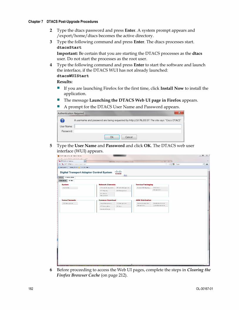
Chapter 7 DTACS Post-Upgrade Procedures
182 OL-30167-01
2 Type the dtacs password and press Enter. A system prompt appears and /export/home/dtacs becomes the active directory.
3 Type the following command and press Enter. The dtacs processes start. dtacsStart
Important: Be certain that you are starting the DTACS processes as the dtacs user. Do not start the processes as the root user.
4 Type the following command and press Enter to start the software and launch the interface, if the DTACS WUI has not already launched: dtacsWUIStart
Results:
If you are launching Firefox for the first time, click Install Now to install the application.
The message Launching the DTACS Web UI page in Firefox appears.
A prompt for the DTACS User Name and Password appears.
5 Type the User Name and Password and click OK. The DTACS web user
interface (WUI) appears.
6 Before proceeding to access the Web UI pages, complete the steps in Clearing the
Firefox Browser Cache (on page 212).

Check DTACS Processes Using the WebUI
OL-30167-01 183
7 Click the Process Status tab to view the processes.
8 Select one of the following to view status processes:
Click Show to view the status of the processes in the current window.
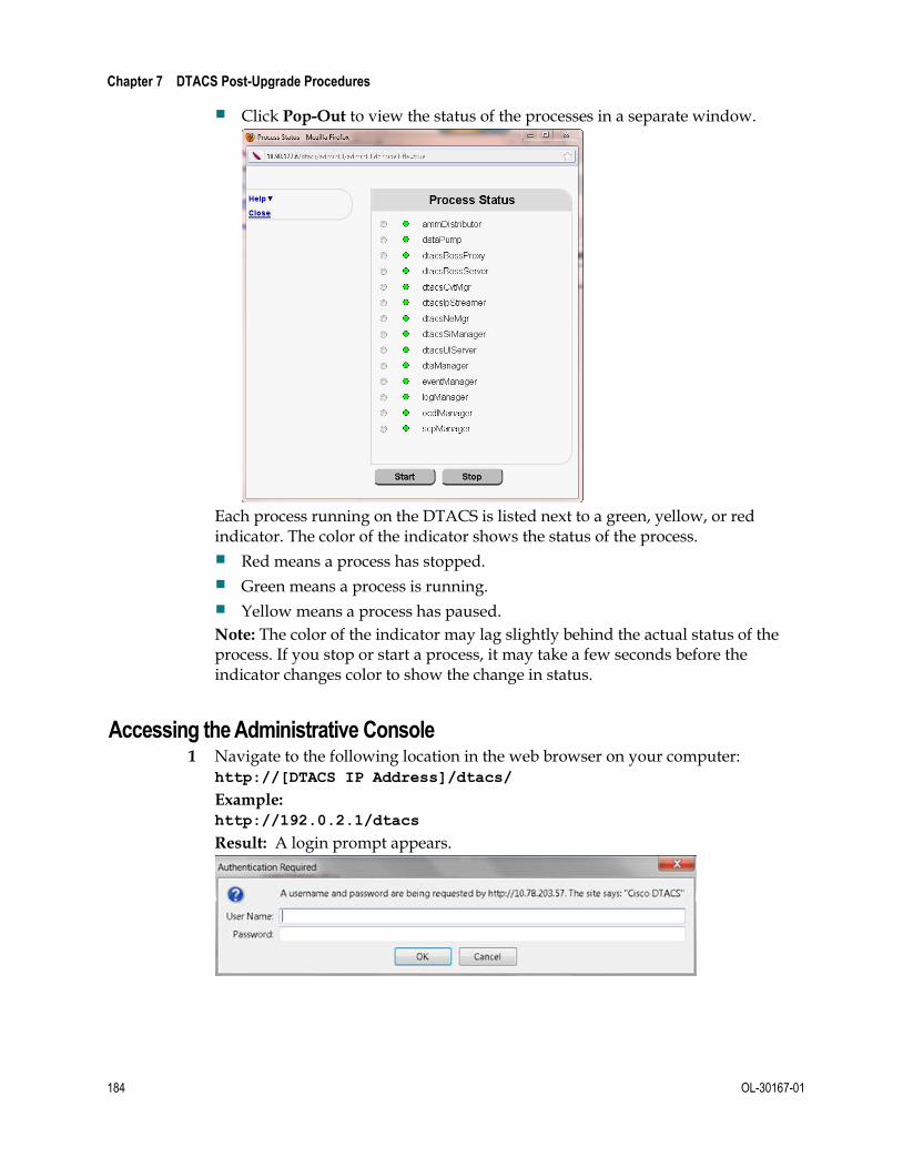
Chapter 7 DTACS Post-Upgrade Procedures
184 OL-30167-01
Click Pop-Out to view the status of the processes in a separate window.
Each process running on the DTACS is listed next to a green, yellow, or red indicator. The color of the indicator shows the status of the process.
Red means a process has stopped.
Green means a process is running.
Yellow means a process has paused.
Note: The color of the indicator may lag slightly behind the actual status of the process. If you stop or start a process, it may take a few seconds before the indicator changes color to show the change in status.
Accessing the Administrative Console 1 Navigate to the following location in the web browser on your computer:
http://[DTACS IP Address]/dtacs/
Example: http://192.0.2.1/dtacs
Result: A login prompt appears.

Check DTACS Processes Using the WebUI
OL-30167-01 185
2 Type your DTACS Administrator username and password, and click OK.
Result: The DTACS Administrative Console opens.
DTACS Processes
The following table briefly describes each of the DTACS processes.
Process Description
ammDistributor This process transmits Authorization Management Messages (AMMs) to Digital Transport Adapters (DTAs).
dataPump This process pumps out encoded images to a specific IP/port combination.
dtacsBossProxy This process handles backend processing of BOSS transactions that are not supported by DTACS.
dtacsBossServer This process provides BOSS interfaces to DTACS.
dtacsCvtMgr This process works with CD2-CVT files. It allows you to create, edit, delete and transmit CD2-CVT file data.
dtacsNeMgr This process provisions and maintains network configurations that are used to setup PID routes and insert Simple Content Protection and Multi-Program Keys.
dtacsIpStreamer Transmits data supplied by other DTACS processes as MPEG elementary streams to specified IP addresses (multicast or unicast).

Chapter 7 DTACS Post-Upgrade Procedures
186 OL-30167-01
Process Description
dtacsSiManager This process generates SI and channel map data.
dtacsUIServer This process proxies WUI requests to the appropriate back-end process(es) and the Informix database. The dtacsUIServer process also returns responses from back-end processes and the database to the WUI.
dtaManager This process provisions and manages DTA devices.
eventManager This process provides a way to notify system components of events.
logManager This process is an internal process that manages debug logging levels of DTACS packages.
ocdlManager This process handles requests from the WUI. It creates and manages associations and related CVTs, encodes images and interacts with the database to persist related data.
scpManager This process provides key management for Simple Content Protection (SCP).

Test dbSync from the DTACS WebUI
OL-30167-01 187
Test dbSync from the DTACS WebUI 1 Click Sys Config in the WUI. The DTACS System Configuration window opens.
2 Click the DB Sync tab and then click DB Sync to initiate the DTACS database synchronization process.
Note: After a few moments, the Status in the DB Sync Status History table is refreshed automatically every three seconds.
3 Select one of the following options:
If the Status is In Progress, wait a few seconds for the status to refresh.
Note: The time taken by the DB Sync process is based upon the amount of data that needs to be synchronized from the EC. We recommend that operators wait to access the DTACS user interfaces until after this process has completed because there may be much data that needs to be updated.
If the Status is Completed and if the entry in the DB Sync End Time column is current, then the synchronization was successful. Go to the next procedure in this chapter.
If the Status is Failed, and if the description reveals that the synchronization is still in progress, repeat this procedure after a few seconds.
Note: Contact Cisco Services if you are not able to synchronize the database successfully.

Chapter 7 DTACS Post-Upgrade Procedures
188 OL-30167-01
Execute the postUpgrade Script on the DTACS Host
The DTACS postUpgrade script performs post-install and post-upgrade checks, enables cron jobs, checks for filesystem space utilization, as well as other functions.
1 Insert the DTACS DVD into the DVD drive of the DTACS server.
2 Type the following command and then press Enter. A list of the mounted file systems appears. df -n
Note: The presence of /cdrom in the output confirms that the system correctly mounted the DVD.
3 As the root user, type the following command and press Enter to source in the DTACS environmental variables: . /dvs/dtacs/bin/dtacsSetup
4 As the root user, type the following command and press Enter. A confirmation message appears. /cdrom/cdrom0/sai/scripts/postUpgrade
5 Type y and press Enter. The system executes the postUpgrade script.

Attach Mirrors After a DVD Live Upgrade
OL-30167-01 189
Attach Mirrors After a DVD Live Upgrade Complete the following procedure only if you have upgraded the DTACS software from a DVD.
Important: Be sure that you complete this procedure during the current maintenance window on the night of the server upgrade. If you wait until the following night to complete this procedure, the server will operate an entire day without its disk-mirroring functions in place.
Important Note to Consider
You should follow the procedure in this chapter only under one of the following circumstances:
You are satisfied with the upgrade and want to commit the system changes. Rolling back an upgrade after completing this procedure is time-consuming and takes significant effort.
You have rolled back from an unsuccessful DVD upgrade and want to synchronize the mirrors.
Attaching Mirrors After a DVD Live Upgrade
In this procedure, you will enable the server's disk-mirroring function of the server. Complete the following steps to log on to the DTACS server and attach the server's mirrors.
Note: It may take up to 60 minutes to complete this process.
1 Verify that the Maintenance DVD is in the DVD drive. If the DVD has been removed, insert it into the DVD drive.
2 Type the following command and then press Enter. A list of the mounted file systems appears. df -n
Note: The presence of /cdrom in the output confirms that the system correctly mounted the DVD.
3 Log on to the DTACS server as the root user.
4 Type the following command and press Enter. A confirmation message appears. /cdrom/cdrom0/sai/scripts/attach_mirrors
5 Type y and press Enter. The system executes a script that attaches submirrors to their respective mirrors.
6 When the disk-mirroring function completes, type eject cdrom and press Enter.
7 Remove the Maintenance DVD from the DVD drive.
8 Type exit and then press Enter. The root user logs out of the DTACS server.

Chapter 7 DTACS Post-Upgrade Procedures
190 OL-30167-01
Restore Image Associations In this procedure, you will restore image associations. Use the sheet of paper on which you recorded information in Note and Delete Image Associations (on page 144).
1 Obtain the sheet of paper on which you recorded your location information and image associations.
2 On the DTACS main window, under Common Download, click Image
Management.
Result: The Image Management window opens.

Restore Image Associations
OL-30167-01 191
3 Click Add.
Result: The Add Image window opens.
4 Using the sheet of paper on which you previously noted the image associations,
add the image data back to the system, clicking Save after each addition. Repeat this process for each image association that you recorded.
Note: The Transmission State needs to be set to On.
Note: For DTACS , Vendor ID and Hardware ID no longer pertain.

Chapter 7 DTACS Post-Upgrade Procedures
192 OL-30167-01
Restore Remote CVTs 1 Obtain the sheet of paper on which you recorded the CVT information in Note
and Delete CVT Provisioning (on page 145).
2 Follow the steps in Add a CVT (on page 103) for all the CVTs on this sheet of paper.
3 Follow these instructions for each CVT on the sheet of paper with a Transmission State of On.
a Complete the steps in Add a CVT Association (on page 111) for these CVTs.
b For each of these CVT associations, select the Transmit State of Non-Group-CVT.
c Repeat Steps a and b for all BSGs.
Notes:
The upgrade will still be successful even if all of the remote CVTs were not deleted.
However, there may be some stale or inconsistent CVT entries (cvt_config and cvt_attr tables) in the database.
Delete any remaining CVTs from the WebUI.
Contact Cisco Services should you encounter any difficulties or if you do not understand the rationale for these steps.

OL-30167-01 193
If You Have Questions
If you have technical questions, call Cisco Services for assistance. Follow the menu options to speak with a service engineer.
Access your company's extranet site to view or order additional technical publications. For accessing instructions, contact the representative who handles your account. Check your extranet site often as the information is updated frequently.
8 Chapter 8 Customer Information

OL-30167-01 195
A Appx auto letter Appendix A Managing DTACS User Accounts This appendix contains procedures for managing user accounts on the Cisco DTACS server. The appendix includes descriptions of user accounts, password expiration rules and role-based access control.
In This Appendix
DTACS Security .................................................................................. 196
Password Management ...................................................................... 203
Password Expiration Period .............................................................. 206

Appendix A Managing DTACS User Accounts
196 OL-30167-01
DTACS Security
Administrative Users
Administrative users (admins) are the only users who can assume the dtacs role. Users who do not have administrative privileges cannot access the DTACS WUI. The following sections include information about managing all types of users.
Operating System Defaults
Operating System: Solaris 10
Security Features:
- Secure by Default - OS is installed with minimal network services
- Networking
SSH is the only network listening service installed by default for remote access; others are set to off or configured for only local machine access
X11 forwarding is also enabled for remote UI access using SSH
- Restricted Network Resources - Authorized users have access to all network resources, but the system itself has very little exposure to the network, making unauthorized access very difficult
- System Monitoring - Basic Security Module (BSM) provides monitoring of system events for logging and auditing
Operating system defaults are set up during system installation.
Important: We recommend that you do not change the system defaults so that you can retain the highest level of system security. Cisco is not responsible for any damage that might occur to your DTACS or network if you choose to change the system defaults.
Role-Based Access Control
We have implemented role-based access control as part of the DTACS operating system. Role-based access control allows system admins to assign control of parts of the system to specific users. System admins can also limit system access to specific users.
A system admin can give users permissions to run certain commands or access to certain files. They can also prevent users from running commands or accessing files. Role-based access control allows increased flexibility in the assignment of system permissions.

DTACS Security
OL-30167-01 197
The following table lists the three most important roles and account types available on the DTACS system. The table also contains a description of their permission levels.
Role/Account
Files Commands Database
Read Write Execute Read Write Alter
Root Y Y Y Y Y Y
DTACS Role Y Y Y Y Y Y
DTACS Admin Account
Y N N N N N
This section is a more detailed description of the roles and accounts available on the DTACS server.
root User
The root user is the system administrator account and has all privileges and rights.
Login access to the system using the root user is limited to direct local access, such as from the local console.
You can switch to the root user from another account that is logged in locally or remotely.
You must use the root user to create all customer-specific login accounts.
The root user has permission to switch to the dtacs role.
The root user is the database administrator.
dtacs Role
The dtacs role is the DTACS application administrator and user.
You should perform all DTACS application activities (including starting and stopping the DTACS applications, WUI access, application file management, diagnostic script execution, and log configuration) using the dtacs role.
You must use the dtacs role to start the Administrative Console.
Access to the dtacs role is limited to the root user and DTACS Administrator accounts. These are the only accounts with permission to switch to the dtacs role.
You cannot log in directly to the DTACS using “dtacs” and the dtacs role password.
The DTACS now uses SFTP instead of FTP, because SFTP is a more secure method of transferring data.
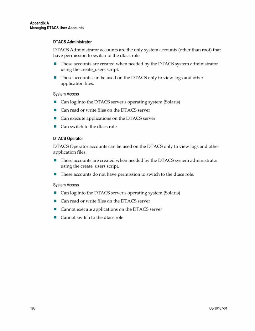
Appendix A Managing DTACS User Accounts
198 OL-30167-01
DTACS Administrator
DTACS Administrator accounts are the only system accounts (other than root) that have permission to switch to the dtacs role.
These accounts are created when needed by the DTACS system administrator using the create_users script.
These accounts can be used on the DTACS only to view logs and other application files.
System Access
Can log into the DTACS server's operating system (Solaris)
Can read or write files on the DTACS server
Can execute applications on the DTACS server
Can switch to the dtacs role
DTACS Operator
DTACS Operator accounts can be used on the DTACS only to view logs and other application files.
These accounts are created when needed by the DTACS system administrator using the create_users script.
These accounts do not have permission to switch to the dtacs role.
System Access
Can log into the DTACS server's operating system (Solaris)
Can read or write files on the DTACS server
Cannot execute applications on the DTACS server
Cannot switch to the dtacs role

DTACS Security
OL-30167-01 199
Regular Users
Regular user accounts do not have permission to view DTACS logs or other application files.
These accounts are created when needed by the DTACS system administrator using the create_users script.
These accounts do not have permission to switch to the dtacs role.
System Access
Can log into the DTACS server's operating system (Solaris)
Cannot read or write files on the DTACS server
Cannot execute applications on the DTACS server
Cannot switch to the dtacs role
User Accounts
This section describes how to create and delete user accounts.
Create a User Account
1 Open an xterm window on the DTACS server.
2 Log in to the DTACS server as root.
3 Type the following command and press Enter: /dvs/admin/create_users
Result: The Choose Type of User to Add menu appears. -------------------------- Choose Type of User to Add -------------------------- 1: Add Regular User (has no DTACS privileges) 2: Add Operator (has DTACS read privileges) 3: Add Administrator (has DTACS read & write privileges) Please enter choice or 'Q' to exit:
4 Select the user type for the account that you want to add.
5 Type the name of the new user account and press Enter. The user name must be between 6 and 8 alphanumeric characters and cannot contain special characters. The Do you wish to continue adding this user (Y/N)? message appears.
6 Type y (for yes) and press Enter.
7 Type the password for the user and press Enter.
8 Type the password for the user again and press Enter. The create_users program exits.

Appendix A Managing DTACS User Accounts
200 OL-30167-01
Delete a User Account
Use this procedure to delete users that were added using the create_users script.
1 Log in to the DTACS server as root.
2 Review the user files in the user's home directory and move any files that should be retained to another directory, outside the user's home directory.
3 In an xterm window, type the following command and press Enter. The system deletes the user's home directory. userdel -r [username]
Note: Substitute the user's name for [username].
4 Type the following command and press Enter. The system removes the user from the /etc/project file. projdel user.[username]
Note: Substitute the user's name for [username].
5 Is the user you are deleting a Regular User?
If yes, type the following command and press Enter. The system deletes the group associated with that user. groupdel [username]
Note: Substitute the user's name for [username].
If no, you are finished with this procedure.
Important: Even when you delete a user, the user's name still exists in the password history file. We recommend that you do not edit this file.
If you delete a user, then add the same user again, the user's old password history remains in effect and the password history file contains the user's last five passwords. The user cannot change their password to one of the five passwords in the password history file.
Who Am I?
To determine who is logged in to a session, you can type one of the following commands from the DTACS server's command line and press Enter:
id
/usr/ucb/whoami
Note: If you add /usr/ucb to your default path, you only need to type whoami and press Enter.
The system returns the user ID of the user currently logged in to the session.

DTACS Security
OL-30167-01 201
Log On
Follow this procedure to log in to the CDE at the DTACS server terminal:
1 At the DTACS server terminal, type your user name and press Enter.
2 At the prompt, type your password and press Enter.
3 Before you execute any DTACS commands (such as dtacsStart or dtacsStop), type sux - dtacs and press Enter.
4 Before you launch any DTACS user interface windows (such as the Administrative Console), type the following commands and press Enter.
export DISPLAY= : 0.0
xhost +
You can only have one active session for SSH, SFTP, and CDE sessions for any user name.
Note: This does not apply to the dtacs role or to the root user.
This restriction can be changed for a user by modifying the project file entry for that user.
Override Session Limitations on DTACS
1 Log in to the DTACS as root.
2 Type the following command and press Enter: projmod -K 'project.max-tasks=(priv,x,deny)' user.[username]
Notes:
The x in (priv,x,deny) is the number of active sessions the user is allowed to have open at a time.
Substitute the user name for [username].

Appendix A Managing DTACS User Accounts
202 OL-30167-01
Session Security Enhancements
The DTACS Server will close a user session that has been idle for a configurable period of time. After a session is closed, users must log back into the system.
Session locking default time: 30 minutes (1800 seconds)
Recovery: User logs in again
Notes:
The session locking time does not affect the root user.
Session locking also affects SSH, xterms, consoles on the CDE, and shells launched during a session.
Important: Whenever you change an environment variable in .profile, you must then source the file. Type . /export/home/dtacs/.profile and press Enter. (Be sure to type a space between the first. and /.) Then run the dtacsStop, dtacsKill, and dtacsStart commands as the dtacs user.
Change the Session Timeout Default for a User
1 Open an xterm window on the DTACS server.
2 Type the following command and press Enter: cd /export/home/[user account]
3 Open the .profile file in a UNIX text editor.
4 Add the following lines to the .profile file:
export TIMEOUT=[seconds] export TMOUT=[seconds]
Notes:
Do not type the brackets [ ] in the command.
Enter the time as a number of seconds.
Examples:
– To enter a session locking time of 5 minutes, add the following lines: export TIMEOUT=300 export TMOUT=300
– To enter a session locking time of 15 minutes, add the following lines: export TIMEOUT=900 export TMOUT=900
We recommend that you keep the session locking time to as short a time as possible. This helps prevent unauthorized use of your system.
5 Save the .profile file and close the text editor.
6 In the xterm window, type the following command and press Enter. The system will use the updated .profile file. . ./.profile
Note: Be sure to type a space between the first two periods.

Password Management
OL-30167-01 203
Password Management Regardless of password management rules enforced by a system, users must still be encouraged to choose difficult to guess passwords. Proper system management of passwords is important but the primary responsibility for strong passwords ultimately rests with the user.
Users must select a very strong password. Strong passwords have the following general characteristics:
Contain 8 or more characters
Contain at least 2 alphanumeric characters and at least one numeric or special character
Do not consist of only one character type (aaaaaaa or 11111111)
Do not contain any aspects of a date
Are not proper names
Are not telephone numbers or similar numeric groups
Are not user IDs, user names, group IDs, or other system identifiers
Do not contain more than two (2) consecutive occurrences of the same character
Are not consecutive keyboard patterns (for example, qwerty)
System Password Retention
The system sets the following restrictions on re-using passwords:
The system retains the last 5 passwords each user uses.
The system does not allow you to re-use any of the last 5 passwords each user has used.
Changing a User Account Password
We recommend that you change the default passwords for the root and for the dtacs role at a minimum to increase the security level on the DTACS. Our recommendations for other account passwords are as follows:
informix account: Changing the informix account password is not necessary since this account is locked by default.
dtacsSSH account: Changing the dtacsSSH account password is not necessary since this user is not directly used by an operator, and the default password is either not known or documented.
easftp and dtacsftp accounts: These account passwords should be done only in coordination with the administrator of the EAS and the VOD systems.
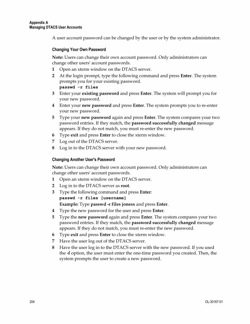
Appendix A Managing DTACS User Accounts
204 OL-30167-01
A user account password can be changed by the user or by the system administrator.
Changing Your Own Password
Note: Users can change their own account password. Only administrators can change other users' account passwords.
1 Open an xterm window on the DTACS server.
2 At the login prompt, type the following command and press Enter. The system prompts you for your existing password. passwd -r files
3 Enter your existing password and press Enter. The system will prompt you for your new password.
4 Enter your new password and press Enter. The system prompts you to re-enter your new password.
5 Type your new password again and press Enter. The system compares your two password entries. If they match, the password successfully changed message appears. If they do not match, you must re-enter the new password.
6 Type exit and press Enter to close the xterm window.
7 Log out of the DTACS server.
8 Log in to the DTACS server with your new password.
Changing Another User's Password
Note: Users can change their own account password. Only administrators can change other users' account passwords.
1 Open an xterm window on the DTACS server.
2 Log in to the DTACS server as root.
3 Type the following command and press Enter: passwd -r files [username]
Example: Type passwd -r files jonesx and press Enter.
4 Type the new password for the user and press Enter.
5 Type the new password again and press Enter. The system compares your two password entries. If they match, the password successfully changed message appears. If they do not match, you must re-enter the new password.
6 Type exit and press Enter to close the xterm window.
7 Have the user log out of the DTACS server.
8 Have the user log in to the DTACS server with the new password. If you used the -f option, the user must enter the one-time password you created. Then, the system prompts the user to create a new password.

Password Management
OL-30167-01 205
Changing the Root Password
Note: Users can change their own account password. Only administrators can change other users' account passwords.
1 Open an xterm window on the DTACS server.
2 Log in to the DTACS server as root.
3 Type the following command and press Enter: passwd -r files root
4 Type the new password for the root user and press Enter.
5 Type the new password again and press Enter. The system changes the root password.

Appendix A Managing DTACS User Accounts
206 OL-30167-01
Password Expiration Period By default, the system requires that all user accounts change their passwords after 13 weeks. The system also displays a warning 2 weeks before the deadline. After that time, if the user has not changed their account password, the user account is locked.
Important: This expiration period is applicable to all users, including root, dtacsSSH, informix, dtacsftp, easftp, any custom accounts, and the dtacs role.
Default number of weeks a password is valid: 13
Default time period from password expiration the user receives a warning message to change passwords: 2
Recovery: Administrator must reset the user account by changing the password
You can change or disable the password expiration period applied when adding new users or changing passwords, and change or disable an individual user's password expiration period.
Change the Password Expiration Period
You can change the password expiration period applied when creating new users or changing passwords.
Important:
New users added to the server after the password expiration period has changed automatically inherit the new password expiration period.
Existing users' individual expiration periods remain in force until the user's password is changed (either by an administrator or by the user).
Unless the system password expiration period is disabled, all user accounts will inherit the system password expiration period each time they change their passwords, even if the user's expiration period has been disabled.
If you set the value of MAXWEEKS to -1, you disable password expiration.
Changing the System Password Expiration Period
Use this procedure to change the password expiration period for the entire system:
1 Open an xterm window on the DTACS server.
2 Log in to the DTACS server as root.
3 Type the following command and press Enter: cd /etc/default
4 Open the passwd file in a UNIX text editor.
5 Locate the following line in the passwd file:
export MAXWEEKS=13

Password Expiration Period
OL-30167-01 207
6 Change the expiration period to the number of weeks that you prefer.
Note: We recommend that you keep the expiration period as short as possible. This helps prevent unauthorized use of your system.
7 Locate the following line in the passwd file:
export WARNWEEKS=2
8 Change the warning period to the number of weeks that you prefer.
9 Save the passwd file and close the text editor.
10 Type exit and press Enter to close the xterm window.
Change a User Password Expiration Period
Use this procedure to change the password expiration period for an individual user account:
1 Open an xterm window on the DTACS server.
2 Log in to the DTACS server as root.
3 Type the following command and press Enter: passwd -r files -x [days] [username]
Notes:
Type the number of days before a user password expired for [days].
Type the username for [username].
4 Verify the expiration period by typing the following command and pressing Enter. passwd -s [username]
Example: Type passwd -s dtacs and press Enter. The system displays a message similar to the following:
dtacs PS 09/02/09 91 14
user pw_status date MIN MAX WARN
The date (09/02/08) is the date the password was set by the user (dtacs).
The MIN (blank) is the minimum number of days before a user is allowed to change the password. We recommend that you leave this field blank.
The MAX (91) is the number of days after the date that the password is valid.
The WARN (14) is the number of days before the password expires that a warning banner is displayed.
Type exit and press Enter to close the xterm window.

Appendix A Managing DTACS User Accounts
208 OL-30167-01
Disable the Password Expiration Period
You can disable the password expiration period that is applied when creating new users or when changing passwords or for an individual user.
Important:
New users added to the server after the password expiration period has changed automatically inherit the new password expiration period.
Existing users' individual expiration periods remain in force until the user's password is changed (either by an administrator or by the user).
Unless the system password expiration period is disabled, all user accounts will inherit the system password expiration period each time they change their passwords, even if the user's expiration period has been disabled.
If you set the value of MAXWEEKS to -1, you disable password expiration.
Disable the Password Expiration Period for the System
Use this procedure to disable the password expiration period for the entire system:
1 Open an xterm window on the DTACS server.
2 Log in to the DTACS server as root.
3 Type the following command and press Enter: cd /etc/default
4 Open the passwd file in a UNIX text editor.
5 Locate the following line in the passwd file: export MAXWEEKS=13
6 Change the expiration period to –1 (negative one).
7 Locate the following line in the passwd file: export WARNWEEKS=2
8 Change the warning period to –1 (negative one).
9 Save the passwd file and close the text editor.
10 In the xterm window, type the following command and press Enter. The system will use the updated passwd file. source . ./passwd
11 Type exit and press Enter to close the xterm window.
Important: Existing users' individual expiration periods remain in force until the user's password is changed (either by an administrator or by the user).
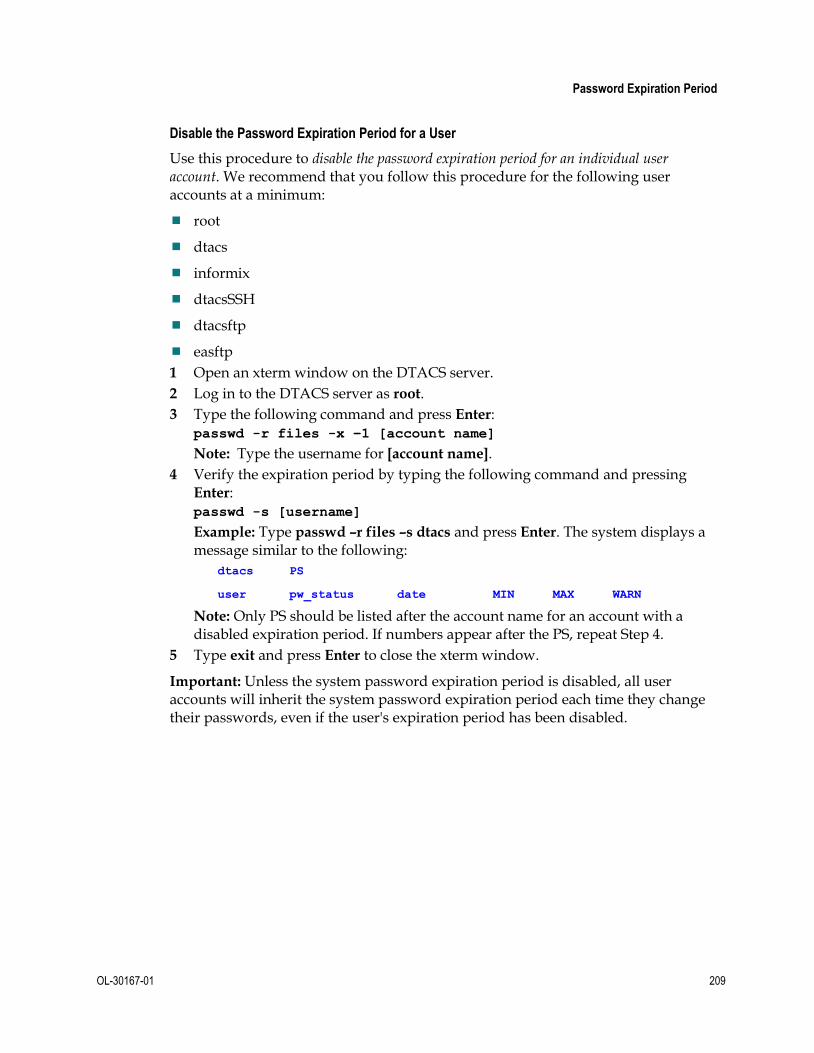
Password Expiration Period
OL-30167-01 209
Disable the Password Expiration Period for a User
Use this procedure to disable the password expiration period for an individual user account. We recommend that you follow this procedure for the following user accounts at a minimum:
root
dtacs
informix
dtacsSSH
dtacsftp
easftp
1 Open an xterm window on the DTACS server.
2 Log in to the DTACS server as root.
3 Type the following command and press Enter: passwd -r files -x –1 [account name]
Note: Type the username for [account name].
4 Verify the expiration period by typing the following command and pressing Enter: passwd -s [username]
Example: Type passwd –r files –s dtacs and press Enter. The system displays a message similar to the following:
dtacs PS
user pw_status date MIN MAX WARN
Note: Only PS should be listed after the account name for an account with a disabled expiration period. If numbers appear after the PS, repeat Step 4.
5 Type exit and press Enter to close the xterm window.
Important: Unless the system password expiration period is disabled, all user accounts will inherit the system password expiration period each time they change their passwords, even if the user's expiration period has been disabled.


OL-30167-01 211
B Appx auto letter Appendix B Troubleshooting the DTACS Server This appendix contains information about procedures that you can use to troubleshoot issues on the Cisco DTACS server.
In This Appendix
Correcting Java Errors in Firefox ...................................................... 212
Creating a New Firefox Profile in Solaris ........................................ 215
Creating a New Firefox Profile in Windows ................................... 218
Correcting Dialog Box Errors in Firefox Version 24ESR ............... 222

Appendix B Troubleshooting the DTACS Server
212 OL-30167-01
Correcting Java Errors in Firefox These procedures may be used to help resolve Firefox exceptions that may occur when using a local computer’s Firefox browser to connect to the remote DTACS server (for example, when using a Firefox browser on a PC to establish a UI connection to the remote DTACS server). These procedures do not apply when the DTACS Firefox browser is exported to a remote machine.
Follow these steps to correct Java errors in Firefox:
1 Clear the Firefox Browser Cache.
2 If the issues are not resolved, stop and restart the Tomcat process.
Clearing the Firefox Browser Cache
With the Firefox browser open on the local machine, perform the following steps in the browser.
Note: The browser does not need to be connected to the DTACS while performing these steps.
If you are using Firefox Version 3.6:
1 Choose Tools > Clear Recent History.
2 In the Time range to clear list, choose Everything.
3 In the Details area, clear the check box beside every item except Cache.
4 Click Clear Now.
5 Close the Firefox browser and re-open it to establish a new connection to the DTACS UIs.
If you are using Firefox Version 3.0:
1 Choose Tools > Clear Private Data.
2 Clear the check box beside every item except Cache.
3 Click Clear Private Data Now.
4 Close the Firefox browser and re-open it to establish a new connection to the DTACS UIs.
Stopping the Tomcat Process
Follow these steps to stop the Tomcat process on the DTACS server:
1 Choose File > Exit from the File menu on the DTACS WUI to close the Firefox browser connection to the DTACS.
2 Open an xterm connection to the DTACS and type su - root to change to the root user.
3 Type the password for the root user at the password prompt.

Correcting Java Errors in Firefox
OL-30167-01 213
4 Type the following command and press Enter to stop the Tomcat process. svcadm disable apache-tomcat
5 Type the following command and press Enter to monitor the state of apache-tomcat. When the state changes to disabled, then proceed with starting apache-tomcat. svcs –a | grep apache-tomcat
Removing Files from the webui Directory
Follow these steps to remove files from the webui work directory on the DTACS server:
1 Type teh following command and press Enter at the root prompt to change to the webui work directory. cd /dvs/dtacs/webui/work
CAUTION:
Verify that you are in the correct directory (/dvs/dtacs/webui/work/) before you type the next command.
When you type the next command you will delete all files in the directory.
2 At the prompt, type pwd and press Enter to verify that you are in the webui work directory. The directory name appears at the system prompt.
3 At the root prompt, type the following command and press Enter to remove all files from the webui work directory. rm -rf*
Starting the Tomcat Process 1 Log into the DTACS as the root user.
2 Type the following command and press Enter to start the Tomcat process. svcadm enable apache-tomcat
3 Type the following command and press Enter to monitor the state of apache-tomcat. When the state changes to online, then proceed to the next step.
svcs –a | grep apache-tomcat
4 Type exit and press Enter to log out the root user.
5 Launch the Firefox browser and connect to the DTACS UI.
If Firefox issues still exist, then call Cisco Services for assistance in resolving the error.

Appendix B Troubleshooting the DTACS Server
214 OL-30167-01
Clearing the Firefox Cache 1 Type cd /export/home/dtacs/.mozilla/ at the root prompt to change to the
Mozilla directory.
2 Type ls at the prompt to verity that the Firefox directory exists.
3 Type cd firefox to change to the Firefox directory
4 Type ls to view all files in the Firefox directory. Note the name of the ******.default directory.
Note: The asterisks (*******) are place holders for the first part of the .default filename.
5 Type cd *******.default to change to the default directory.
6 Type ls to view the contents of the default directory. Verify that the Cache directory exists.
7 Type cd Cache to change to the Cache directory.
8 Type ls to view the contents of the Cache directory.
CAUTION:
Verify that you are in the Firefox Cache directory (/export/home/dtacs/.mozilla/firefox/*******.default/Cache/) before you type the next command.
When you type the next command you will delete all files in the directory.
9 Type pwd at the prompt to verify that you are in the Firefox Cache directory. The directory name appears at the system prompt.
10 Type rm -rf * to remove files in the directory.
11 Type ls at the prompt to verify that all files have been removed from the directory.
12 Start the DTACS WUI.
Note: After restarting Tomcat, wait for few minutes before opening DTACS WUIs. The Tomcat server takes several minutes to restart and bind to the DTACS WUI interface.

Creating a New Firefox Profile in Solaris
OL-30167-01 215
Creating a New Firefox Profile in Solaris The Firefox Profile Manager allows you to create an additional profile while retaining your original profiles. This is useful, not only for having separate settings for multiple users, but also for avoiding HTTP sessions between opened browsers.
Important: Do not delete any existing profiles unless you are absolutely sure that you will never need them again.
1 If Firefox is running, close it completely.
2 Type the following command and press Enter to open the Firefox profile manager: /opt/sfw/lib/firefox3/firefox -no-remote -ProfileManager
Result: The Choose User Profile window opens.
3 Click Create Profile.
Result: The Create Profile Wizard window opens.

Appendix B Troubleshooting the DTACS Server
216 OL-30167-01
4 Click Next.
5 In the Enter new profile name text box that becomes available, type in a name and click Finish.
Result: The Choose User Profile window opens.
6 Un-check the Don't ask at startup field.
Note: You can change this later.

Creating a New Firefox Profile in Solaris
OL-30167-01 217
7 Click Start Firefox to have Firefox start up with the user that you have selected.
Notes:
The Firefox - Choose User Profile window will now appear whenever you start Firefox. If you decide that you no longer want to see this window, check the Don't ask at startup field the next time it appears. The last selected profile will then start automatically when you next start Firefox. You will need to start the Profile Manager again to switch profiles. You can select one of the available profiles and start Firefox.
Alternatively, you can start Firefox through the command line, as described in the following bullets:
- To start a Firefox linking the created profile dtacs1:
/opt/sfw/lib/firefox3/firefox –P dtacs1 –no-remote
http://localhost:8045/dtacs
- To start a Firefox linking the created profile dtacs2:
/opt/sfw/lib/firefox3/firefox –P dtacs2 –no-remote
http://localhost:8045/dtacs
Result: Firefox browsers will now work with two different profiles, with no clash between them.

Appendix B Troubleshooting the DTACS Server
218 OL-30167-01
Creating a New Firefox Profile in Windows The Firefox Profile Manager allows you to create an additional profile while retaining your original one. This is useful, not only for having separate settings for multiple users, but also for simultaneous access to same WUIs with multiple windows.
Important: Do not delete any existing profile unless you are absolutely sure that you will never need it again.
Note: The following set of instructions assumes a standard Firefox installation on a standard Windows operating system.
1 If Firefox is running, close it completely by choosing File > Exit.
2 Click Run from the Windows Start menu.
3 Type the following command and press Enter: firefox.exe -P
4 Click OK.
Result: The Choose User Profile window opens.

Creating a New Firefox Profile in Windows
OL-30167-01 219
5 Click Create Profile.
Result: The Create Profile Wizard window opens.
6 Click Next.
7 In the Enter new profile name text field that becomes available, type in a new profile name and click Finish.
Important: Do not click Choose Folder unless you are familiar with the warnings provided under Custom profile location for Firefox.
Result: The Choose User Profile window opens.

Appendix B Troubleshooting the DTACS Server
220 OL-30167-01
8 On the Choose User Profile window, uncheck the Don't ask at startup check box.
Note: You can change this later.
9 Click Start Firefox to start Firefox with the new profile.
Note: The 'Firefox - Choose User Profile' window will now appear whenever you start Firefox. If you decide that you no longer want to see this window, check the Don't ask at startup check box the next time it appears. The last selected profile will then start automatically when you next start Firefox. You must start the Profile Manager again to switch profiles.

Creating a New Firefox Profile in Windows
OL-30167-01 221
Linking Profiles to Firefox
This procedure describes how to create a shortcut to Firefox by linking to the created profiles.
1 Right-click firefox.exe and select Properties.
Result: The Mozilla Firefox Properties window opens.
2 Click the Shortcut tab (if it is not already selected). Then, in the Target field, type
the following command and press Enter.
"<firefox installation path>\firefox.exe" –p <New Profile
Name> -no-remote
Note: The quotation marks are required.
Example: "C:\Program Files (x86)\Mozilla Firefox\firefox.exe" –p dtacs1 -no-remote
3 Create as many shortcuts as the number of profiles you have created.
4 Type the following command in the Run dialog box and press Enter to run Firefox: firefox –p <profile name> -no-remote

Appendix B Troubleshooting the DTACS Server
222 OL-30167-01
Correcting Dialog Box Errors in Firefox Version 24ESR
This procedure should be used to help resolve the Firefox issue of creating additional dialog boxes while launching the application. This issue may occur in Firefox Version 24 ESR.
Follow these steps to prevent the additional Firefox dialogs boxes from being created:
1 Copy the Preference name "dom.successive_dialog_time_limit" into memory.
2 Type about:config into the URL text field.
3 Did a warning message appear?
If yes, click I'll be careful, I Promise.
If no, go to the next step.
4 Right-click in the Preferences area and choose New > Integer.
5 Paste the Preference name (copied into memory in Step 1) and click OK.
6 Enter 0 (zero) and click OK.
Note: Whenever there are changes in the Firefox version auto-upgrade, be sure that this configuration is retained.

OL-30167-01 223
C Appx auto letter Appendix C Backup and Restore the DTACS File System and Database This appendix contains procedures to save up data on the Cisco DTACS to tape media. This stored information can be used to restore the DTACS if the system suffers an outage.
In This Appendix
Back Up the DTACS File System ...................................................... 224
Back Up the DTACS Database .......................................................... 226
Restore the DTACS File System ........................................................ 228
Restore the DTACS Database ............................................................ 230

Appendix C Backup and Restore the DTACS File System and Database
224 OL-30167-01
Back Up the DTACS File System Consider the following points about a backup of the DTACS server file system:
System Shutdown No Longer Required for File System Backups
System operators do not have to shut down their system in order to back up the DTACS server file system.
Important: Even though you are not required to shut down the system components, we recommend that you schedule your file system backups for periods of lowest system activity.
Recommended Frequency
We recommend that you perform a complete system backup at least once a month, just prior to upgrading to new system software, and immediately after the upgrade.
Filesystem Backup Script Options
The script that backs up the file system is called backupFileSystems. You can run the backupFileSystems script with the following options:
-l — Local-tape-drive. Specifies tape drive to use on local host computer.
(for example - /dev/rmt/0h)
-r — Remote-tape-drive. Specifies tape drive on a remote host computer.
(for example - sparky:/dev/rmt/0h or 192.0.2.1:/dev/rmt/0h)
-B — Backup directory. Specifies the directory to which the backup of the file system will be saved.
The backup directory must be on an NFS-mounted filesystem.
-v — verbose. Verbose output.
-t — Tape label. Backup tape label. This must be a unique string with no spaces.
-h — Help. Provides a brief description of the valid options.

Back Up the DTACS File System
OL-30167-01 225
Backing Up the DTACS File System 1 Insert the DVD labeled similarly to DTACS Install/Upgrade DVD into the DVD
drive of the DTACS server.
Note: Insert the DVD associated with the version that the DTACS is currently running. For example, if you are currently running DTACS Version 3.x.0.14, the install/upgrade DVD associated with Version 3.x.0.14 should be used.
2 Type df -n and press Enter. A list of mounted file systems appears.
Note: The presence of /cdrom in the output confirms that the system correctly mounted the DVD.
3 Label a blank tape with the following information:
DTACS File System Backup [Date] [Site Name] [Software Version] DTACS DVD x.x.x
4 Log in as the root user.
5 Insert the blank tape into the tape drive of DTACS server and wait for the green light to stop flashing.
6 Type the following command and press Enter. The system backs up the DTACS file system, ejects the tape, and displays a message when the backup is complete. /cdrom/cdrom0/sai/backup_restore/backupFileSystems -v
7 When the backup is complete, remove the tape and store it in a safe place.
8 Type eject cdrom and then press Enter.

Appendix C Backup and Restore the DTACS File System and Database
226 OL-30167-01
Back Up the DTACS Database This section provides procedures for backing up the DTACS database to tape.
Database Backup Script Options
The script that backs up the databases is called backupDatabase. You can run the backupDatabase script with the following options:
-b — Blocks. Specifies the block size of the tape device to which the database backup is written.
Note: If -b is not specified, the system uses a default tape block size appropriate for your tape drive. If the system is unable to determine your tape drive, the system uses 32.
-s — Size. Specifies the size of the tape device to which the database backup is written.
If -s is not specified, the system uses a default tape size appropriate for your tape drive. If the system is unable to determine your tape drive, the system uses 8000000.
-l — Local-tape-drive. Specifies tape drive to use on local host. (for example - /dev/rmt/0h)
-r — Remote-tape-drive. Specifies tape drive on a remote host. (for example - sparky: /dev/rmt/0h or 192.0.2.1: /dev/rmt/0h)
-c — Check-database. Checks the integrity of the databases. (Does not fix if errors are found.)
-n — Non-interactive. Non-interactive, useful when running from cron.
-v — Verbose. Verbose output.
-h — Help. Provides a brief description of the valid options.
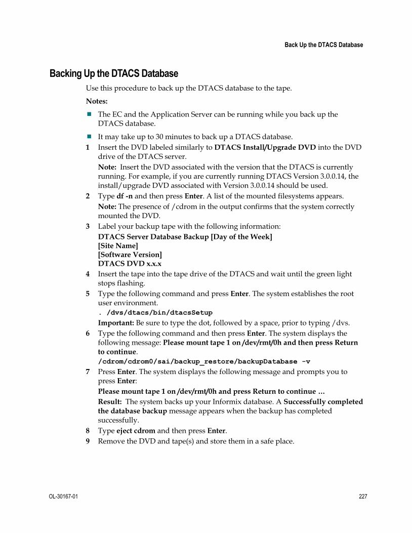
Back Up the DTACS Database
OL-30167-01 227
Backing Up the DTACS Database
Use this procedure to back up the DTACS database to the tape.
Notes:
The EC and the Application Server can be running while you back up the DTACS database.
It may take up to 30 minutes to back up a DTACS database.
1 Insert the DVD labeled similarly to DTACS Install/Upgrade DVD into the DVD drive of the DTACS server.
Note: Insert the DVD associated with the version that the DTACS is currently running. For example, if you are currently running DTACS Version 3.0.0.14, the install/upgrade DVD associated with Version 3.0.0.14 should be used.
2 Type df -n and then press Enter. A list of the mounted filesystems appears.
Note: The presence of /cdrom in the output confirms that the system correctly mounted the DVD.
3 Label your backup tape with the following information:
DTACS Server Database Backup [Day of the Week] [Site Name] [Software Version] DTACS DVD x.x.x
4 Insert the tape into the tape drive of the DTACS and wait until the green light stops flashing.
5 Type the following command and press Enter. The system establishes the root user environment. . /dvs/dtacs/bin/dtacsSetup
Important: Be sure to type the dot, followed by a space, prior to typing /dvs.
6 Type the following command and then press Enter. The system displays the following message: Please mount tape 1 on /dev/rmt/0h and then press Return
to continue. /cdrom/cdrom0/sai/backup_restore/backupDatabase -v
7 Press Enter. The system displays the following message and prompts you to press Enter:
Please mount tape 1 on /dev/rmt/0h and press Return to continue …
Result: The system backs up your Informix database. A Successfully completed
the database backup message appears when the backup has completed successfully.
8 Type eject cdrom and then press Enter.
9 Remove the DVD and tape(s) and store them in a safe place.

Appendix C Backup and Restore the DTACS File System and Database
228 OL-30167-01
Restore the DTACS File System Consider the following points about the restoration of the DTACS file system:
Prerequisite
You need the tape from your most recent backup of the file system before restoring the file system.
Important: Be sure your tapes are write-protected before you use them to restore the system.
File System Restore Script Options
The script that restores the DTACS file system is called restoreFileSystems. You can run the restoreFileSystems script with the following options:
-l - Local-tape-drive. Specifies tape drive to use on local host computer.
(for example - /dev/rmt/0h)
-r - Remote-tape-drive. Specifies tape drive on a remote host computer.
(for example - sparky:/dev/rmt/0h or 192.0.2.1: /dev/rmt/0h)
-B - Backup directory. Specifies the directory that contains the backup from which the file system will be restored. The backup directory must be on an NFS-mounted filesystem.
-v - Verbose. Verbose output.
-i - Interactive. Runs the restoration script in interactive mode.
-h - Help. Provides a brief description of the valid options.
Note: The -l, -r, and -B options are mutually exclusive of one another; only one of them can be used.
Restoring the DTACS File System
Complete the following steps to prepare to restore the DTACS file system:
Important: You need to know the IP address and the netmask of the DTACS server in order to complete this procedure.
1 As dtacs user, type dtacsStop and press Enter. The DTACS processes are stopped.
2 As dtacs user, type dtacsKill and press Enter to ensure that the DTACS processes have stopped.
Restore the DTACS File System
OL-30167-01 229
3 Insert the DVD labeled similarly to DTACS Install/Upgrade DVD into the DVD drive on the DTACS server.
Note: Insert the DVD associated with the version that the DTACS is currently running. For example, if you are currently running DTACS Version 3.0.0.14, the install/upgrade DVD associated with Version 3.0.0.14 should be used.
4 Type the following command and press Enter. The system halts all processes and an ok prompt appears. shutdown -y -g0 -i0
5 At the ok prompt, type the following command and press Enter. The DTACS server boots into the OpenWindows environment. boot cdrom - SAshell
6 Type the following command and press Enter. The system restores the DTACS file system and displays a message when the restoration completes. cdrom/cdrom0/sai/backup_restore/restoreFileSystems -v
7 Type the following command and press Enter. The DTACS server reboots. shutdown -y -g0 -i6
8 Log in as the root user.
9 Follow the procedures in Restore the DTACS Database (on page 230) to restore the DTACS database. After restoring the database, return to Step 10 in this procedure.
10 Type the following command and press Enter. The system warns you that the submirrors for controller 2 will be attached. /cdrom/cdrom0/sai/backup_restore/mirrState -a
11 Type y and press Enter to proceed. The system enables the disk mirroring functions on the DTACS server.
Note: This could take up to an hour to complete.
12 Type eject cdrom and press Enter. The system eject the DVD.
13 As dtacs user (sux - dtacs), type dtacsStart and press Enter. The DTACS processes are started.

Appendix C Backup and Restore the DTACS File System and Database
230 OL-30167-01
Restore the DTACS Database This section contains information that guides you through the process of restoring the DTACS database.
Database Restore Script Options
The script that restores the database is called restoreDatabase. You can run the restoreDatabase script with the following options:
-l — Local-tape-drive. Specifies tape drive to use on local host.
(for example - /dev/rmt/0h)
-r — Remote-tape-drive. Specifies tape drive on a remote host.
(for example - sparky: /dev/rmt/0h or 192.0.2.1: /dev/rmt/0h)
-c — Check-database. Checks the integrity of the databases. (Does not fix if errors are found.)
-v — Verbose. Verbose output.
-p — Physical-restore. Performs only a physical restoration of the database and does not restore the logical logs.
-i — Interactive. Runs the restoration in interactive mode.
-h — Help. Provides a brief description of the valid options.
Restoring the DTACS Database
Complete the following steps to restore the DTACS database.
Note: You need the tape from your most recent database backup in order to restore the DTACS database.
Important: Be sure your tape is write-protected before you use it to restore the database.
1 As dtacs user (sux - dtacs), type dtacsStop and press Enter. The DTACS processes are stopped.
2 As dtacs user, type dtacsKill and press Enter to ensure that the DTACS processes have stopped.
3 If necessary, open an xterm window on the DTACS.
4 As the root user, type the following command and press Enter. The system established the root user environment. . /dvs/dtacs/bin/dtacsSetup
Important: Be sure to type the dot, followed by a space, prior to typing /dvs.

Restore the DTACS Database
OL-30167-01 231
5 Type the following command and press Enter: /export/home/informix/libexec/formatDbSpace
Note: If this command fails or generates an error message, contact Cisco Services for assistance.
6 Insert the DVD labeled similarly to DTACS Install/Upgrade DVD into the DVD drive of the DTACS server.
Note: Insert the DVD associated with the version that the DTACS is currently running. For example, if you are currently running DTACS Version 3.x.0.14, the install/upgrade DVD associated with Version 3.x.0.14 should be used.
7 Insert your most recent copy of the DTACS database backup tape into the tape drive of the DTACS and wait for the green light on the tape drive to stop flashing.
8 Type the following command and press Enter. The Is there more than 1 tape in
this backup? [Y/N] message appears. /cdrom/cdrom0/sai/backup_restore/restoreDatabase -v
9 Type n and press Enter. The system displays a message about ensuring that the backup tape is in the drive.
10 Press Enter. The system restores the database.
11 When the Successfully restored the database message appears, remove the tape and store it in a safe place.
12 Did you restore the file system on the DTACS server?
If yes, return to Step 10 in Restoring the DTACS File System (on page 228).
If no, go to Step 13.
13 As dtacs user (sux - dtacs), type dtacsStart and press Enter. The DTACS processes are started.
Possible Error Condition
After completing the file system and database restoration, in some cases the following error message may appear when you try to restart the DTACS processes:
error: Can't connect to localhost:18090 (connect: Connection refused)
No interfaces up to talk to dncsInitd
Should this error appear on your system, follow these instructions:
1 Log in to the system as the root user.
2 Type the following command and press Enter: rm /etc/no_system_start
3 Log in to the system as dtacs user.
4 Rerun the dtacsStart command.


OL-30167-01 233
D Appx auto letter Appendix D DTACS Rollback Procedure These Cisco DTACS rollback procedures are intended for field service engineers who encounter problems while upgrading an existing DTACS system. Prior to executing the DTACS rollback procedures, contact Cisco Services.
In This Appendix
Which Rollback Procedure Should I Use? ....................................... 234
Activate the Old System Release ...................................................... 235

Appendix D DTACS Rollback Procedure
234 OL-30167-01
Which Rollback Procedure Should I Use? Three rollback procedures exist for rolling back the DTACS upgrade. Read the following choices to help you decide which rollback procedure to use:
If you need to roll back a major upgrade, and you have not already run the procedure under Attach Mirrors After a DVD Live Upgrade, then use the procedure under Activate the Old System Release (on page 235) to roll back.
Note: It should take you about 10 minutes to roll back the T5220 or T5440 DTACS server using this procedure.
If you need to roll back a major upgrade, and you have already run the procedure under Attach Mirrors After a DVD Live Upgrade, then use the procedures to restore the DTACS file system and database in Backup and Restore the DTACS File System and Database.
Note: It may take as long an hour to roll back the T5220 or T5440 DTACS server.

Activate the Old System Release
OL-30167-01 235
Activate the Old System Release
Restoring the Old System Release
Follow this procedure to restore the system software that was in place prior to the unsuccessful upgrade to the DTACS:
1 Write down the version of the system release are that you trying to restore: ___________________
2 If necessary, as the dtacs user (sux - dtacs), type dtacsStop and press Enter to stop the DTACS processes.
3 As the root user, type the following command and press Enter to stop all active sessions: killActiveSessions
4 As the root user, type the following command and press Enter. The system resets the default boot device to the original disk. eeprom boot-device=disk:a
5 Type the following command and press Enter. The system reboots and activates the old software. shutdown -y -g0 -i6
Important: Do not use the reboot or halt command to reboot the server.
6 Did the DTACS reboot without error?
If yes, go to Step 7.
If no, contact Cisco Services.
7 Log in to the CDE of the DTACS server as admin user.
8 Open the EC WUI and navigate to EC->Network Element Provisioning->QAM, Then, select the list of the GQAMs that serve the DTACS and reset them.
9 As dtacs user, type dtacsStart and press Enter. The DTACS processes are started.
10 Change to the root user.
11 If present, remove the DTACS DVD from the server and insert the DVD pertaining to the previous system release.
12 Type the following command and press Enter to attach mirrors: /cdrom/cdrom/sai/scripts/attach_mirrors


OL-30167-01 237
E Appx auto letter Appendix E Enable RADIUS and LDAP Support in a DBDS for DTACS-3.0
Introduction
To configure RADIUS and LDAP, refer to Enabling RADIUS and LDAP Support for DTACS 3.0 (part number OL-31517).


OL-30167-01 239
F Appx auto letter Appendix F Check the Core Files on the DTACS Server
Introduction
This appendix describes how to run the dtacsHealthCheck utility which system operators can use to examine core files on the Cisco DTACS server.
In This Appendix
Checking the Core Files on the DTACS Server .............................. 240

Appendix F Check the Core Files on the DTACS Server
240 OL-30167-01
Checking the Core Files on the DTACS Server DTACS 3.0 is provided with a utility called dtacsHealthChecker than can be used to fetch core file information. System operators should use the -g option when running the utility. The -g option fetches general information, such as installed software information, database utilization, database extents, and core file information. Follow these instructions to run the dtacsHealthChecker utility.
1 Log in to the DTACS and be sure that you are running in the dtacs role.
2 In the DTACS console, type the following command and press Enter to change to the /dvs/dtacs/bin directory: cd /dvs/dtacs/bin
3 Type the following command and press Enter: ./dtacsHealthChecker –g
4 Examine the output for the List of the last 10 core events label. This list contains data pertaining to the DTACS core files.


Americas Headquarters Cisco Systems, Inc. 170 West Tasman Drive San Jose, CA 95134-1706 USA
http://www.cisco.com Tel: 408 526-4000
800 553-6387 Fax: 408 527-0883
This document includes various trademarks of Cisco Systems, Inc. Please see the Notices section of this document for a list of the Cisco Systems, Inc. trademarks used in this document. Product and service availability are subject to change without notice.
© 2014 Cisco and/or its affiliates. All rights reserved. April 2014
Part Number OL-30167-01