Embed Size (px)
Citation preview

dsPIC® DSC Introductory Seminar
© 2004, Microchip Technology Incorporated, All Rights Reserved.
1
© 2005 Microchip Technology Incorporated dsPIC® DSC Introductory Seminar Slide 1
dsPIC®
Digital Signal Controller (DSC) Introductory Seminar
2005
30 MIPS Computing Power in a 6x6 mm Package
© 2005 Microchip Technology Incorporated dsPIC® DSC Introductory Seminar Slide 2
Seminar Agenda
Session Time
Corporate Overview 9:00—9:15am
Architecture 9:15—10:30am
Break 10:30—10:45am
MPLAB® VDI Demonstration 10:45—11:15am
Peripherals 11:15—11:50am
Live Demonstrations 11:50—12:30pm
Lunch 12:30—1:30pm
Software/Hardware Tools 1:30—1:50pm
Hands-on 1:50—2:50pm
Libraries/Applications 2:50—3:15pm
Session Wrap-up 3:15—3:30pm
dsPIC® DSC Introductory Seminar
© 2004, Microchip Technology Incorporated, All Rights Reserved.
2
© 2005 Microchip Technology Incorporated dsPIC® DSC Introductory Seminar Slide 3
Learning Objectives
What is a Digital Signal Controller
Identify key dsPIC® DSC architecture features
Identify key dsPIC DSC DSP architecture features
Identify the advanced dsPIC DSC peripheral set
What software development tools are available
What hardware development tools are available
What software libraries are available
What application libraries are available
Where do you go from here
© 2005 Microchip Technology Incorporated dsPIC® DSC Introductory Seminar Slide 4
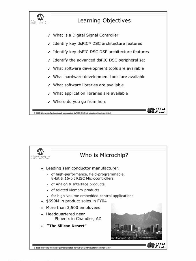
Who is Microchip?
Leading semiconductor manufacturer:
of high-performance, field-programmable, 8-bit & 16-bit RISC Microcontrollers
of Analog & Interface products
of related Memory products
for high-volume embedded control applications
$699M in product sales in FY04
More than 3,500 employees
Headquartered nearPhoenix in Chandler, AZ
“The Silicon Desert”

dsPIC® DSC Introductory Seminar
© 2004, Microchip Technology Incorporated, All Rights Reserved.
3
© 2005 Microchip Technology Incorporated dsPIC® DSC Introductory Seminar Slide 5
Worldwide Technical Support Centers & Manufacturing Facilities
DetroitChicagoToronto
BostonSan JoseLos Angeles New York
DallasAtlanta
LondonParis
MilanMunich
Bangalore Hong Kong
Seoul
Shenzhen
Beijing •.•.
Phoenix
Kaohsiung
ChengduFuzhou
Sydney
Kokomo
•.Copenhagen
•.Qingdao
Arizona Manufacturing and
Corporate HQ
OregonManufacturing
Bangkok Test & Assembly
Shanghai
Shanghai Test & Assembly
Singapore
Shin-Yokohama
Taipei
© 2005 Microchip Technology Incorporated dsPIC® DSC Introductory Seminar Slide 6
Worldwide 8-Bit Microcontroller Market Share (Units)
Based on unit shipment volume 1990-2002, Source: Dataquest, July 2003
1990 1991 1992 1993 1994 1995/96 1997-01 2002-2004No. Rank Rank Rank Rank Rank Rank Rank Rank1 Motorola Motorola Motorola Motorola Motorola Motorola Motorola Microchip2 Mitsubishi Mitsubishi Mitsubishi Mitsubishi Mitsubishi Mitsubishi Microchip Motorola3 NEC NEC Intel NEC NEC SGS-Thomson ST-Micro ST-Micro4 Intel Intel NEC Hitachi Philips NEC NEC NEC5 Hitachi Hitachi Philips Philips Intel Microchip Philips Atmel6 Philips Philips Hitachi Intel Microchip Philips Atmel Sunplus7 Matsushita Matsushita Matsushita SGS-Thomson Zilog Zilog Hitachi Hitachi8 National SGS-Thomson SGS-Thomson Microchip SGS-Thomson Hitachi Toshiba Fijitsu9 Siemens Siemens National Matsushita Matsushita Fujitsu Samsung Philips10 TI TI TI Toshiba Hitachi Intel Elan Toshiba11 Sharp National Zilog National Toshiba Siemens Zilog Mitsubishi12 Oki Toshiba Toshiba Zilog National Toshiba Matsushita Samsung13 Toshiba Sony Siemens TI TI Matsushita Infineon Elan14 SGS-Thomson Sharp Microchip Siemens Ricoh TI Fujitsu Winbond15 Zilog Oki Sharp Sharp Fujitsu National Mitsubishi Zilog16 Matra MHS Zilog Sanyo Oki Siemens Temic Sanyo Sanyo17 Sony Microchip Matra MHS Sony Sharp Sanyo Winbond Matsushita18 Fujitsu Matra MHS Sony Sanyo Oki Ricoh National Infineon19 AMD Fujitsu Oki Fujitsu Sony Oki Sony Holtek20 Microchip Sanyo Fujitsu AMD Temic Sharp Holtek National

dsPIC® DSC Introductory Seminar
© 2004, Microchip Technology Incorporated, All Rights Reserved.
4
© 2005 Microchip Technology Incorporated dsPIC® DSC Introductory Seminar Slide 7
PIC® MicrocontrollerProduct Migration Path
80/84-PinFamily64/68-Pin
Family40/44-Pin
Family28-PinFamily
18/20-PinFamily
14-PinFamily
.5K—2K Words
1K—2K Words
.5K—4K Words
.5K—16K Words
2K—16K Words
4K—64K Words
8K—64K Words
Seamless Migration
212 ProductsFlash, OTP and ROM Superior Analog functionalityOutstanding Flash enduranceIndustry’s strongest product and family migration path
8-PinFamily
© 2005 Microchip Technology Incorporated dsPIC® DSC Introductory Seminar Slide 8
Where Are We Today?RF
Xmit/receive IR
Commu-nications
PowerDrivers
MotorsRelays
Print-heads
DigitalPeripherals
PWMRTC
LEDDrivers
LCDDrivers
AmplifiersSensors Filters
SRAM
A/D
Microcontrollers D/A
PrecisionVoltage
Reference
Bus Comm.- CAN bus - USB- LinBus
PowerManagementPower
High Voltage
I/O’s
TelecomDTMFCodec
Serial NVMemory
Digital Pot
Xceivers- RS232/485- CAN bus- USB
Offered by Microchip

dsPIC® DSC Introductory Seminar
© 2004, Microchip Technology Incorporated, All Rights Reserved.
5
© 2005 Microchip Technology Incorporated dsPIC® DSC Introductory Seminar Slide 9
Seminar Agenda
Session Time
Corporate Overview 9:00—9:15am
Architecture 9:15—10:30am
Break 10:30—10:45am
MPLAB® VDI Demonstration 10:45—11:15am
Peripherals 11:15—11:50am
Live Demonstrations 11:50—12:30pm
Lunch 12:30—1:30pm
Software/Hardware Tools 1:30—1:50pm
Hands-on 1:50—2:50pm
Libraries/Applications 2:50—3:15pm
Session Wrap-up 3:15—3:30pm
© 2005 Microchip Technology Incorporated dsPIC® DSC Introductory Seminar Slide 10
16-bit Digital Signal Controller
Architecture
dsPIC® DSC Introductory Seminar
© 2004, Microchip Technology Incorporated, All Rights Reserved.
6
© 2005 Microchip Technology Incorporated dsPIC® DSC Introductory Seminar Slide 11
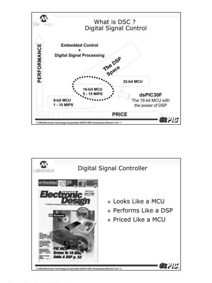
The DSP
Space
8-bit MCU1 - 10 MIPS
16-bit MCU5 - 15 MIPS
32-bit MCU
PRICE
PER
FOR
MA
NC
E
What is DSC ?Digital Signal Control
Embedded Control+
Digital Signal Processing
dsPIC30FThe 16-bit MCU with
the power of DSP
© 2005 Microchip Technology Incorporated dsPIC® DSC Introductory Seminar Slide 12
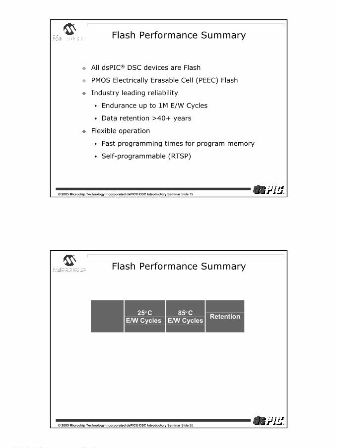
Digital Signal Controller
Looks Like a MCU
Performs Like a DSP
Priced Like a MCU

dsPIC® DSC Introductory Seminar
© 2004, Microchip Technology Incorporated, All Rights Reserved.
7
© 2005 Microchip Technology Incorporated dsPIC® DSC Introductory Seminar Slide 13
Why DSC?
100% Flash with automotive quality
Innovation with new hardware modules
Focus on low pin count with migration option from day 1 on.
Up to 30 MIPS performance
Focus on ease-of-use with common tools
DS
© 2005 Microchip Technology Incorporated dsPIC® DSC Introductory Seminar Slide 14
dsPIC30F Controller Family
Flash Program Memory: 12 K—144 KbytesRAM 512—8 KbytesData EEPROM 1K—4 KbytesPin-count 18—80 pinsTimers 16-bit Up to 5Input Capture Up to 8Output Compare/PWM Up to 8 (individual time bases)Motor Control PWM 6 or 8 with shutdown pinsA/D converter 10-bit, 1 Msps, up to 16 ch A/D converter 12-bit, 200 ksps, up to 16 chUART 1—2SPI™ (8-/16-bit) 1—2I2C™ 1QEI 1Codec interface 1CAN 1—2

dsPIC® DSC Introductory Seminar
© 2004, Microchip Technology Incorporated, All Rights Reserved.
8
© 2005 Microchip Technology Incorporated dsPIC® DSC Introductory Seminar Slide 15
High performance 16-bit CPU with industry leading C compiler efficiency
Seamless integration of DSP and MCU functionality
Flexible, reliable Flash program memory
Wide operating voltage range (2.5V—5.5 V)
Fast, deterministic interrupt system—5 cycle latency
Competitive DSP performance
Advanced peripheral I/O features
Fast, precise 10- & 12-bit A-to-D Converters
Data EEPROM and SRAM
In-circuit debug capabilities
Designed for the Pole Position
© 2005 Microchip Technology Incorporated dsPIC® DSC Introductory Seminar Slide 16
194%186%
161%
100%108%
118%
141%
C Compiler Efficiency
Nea
rest
Com
pet
itor
Furt
hes
t Com
pet
itor
dsP
IC30F
dsPIC30F includes features to enhance C code
efficiency
⇓New instruction types
+
More flexible addressing
+
Software stack
=
Smallest C code
32-bit math-intensive code16-bit competition(~ 50KB code)
EEMBC industry std. Benchmarks, Automotive Suite

dsPIC® DSC Introductory Seminar
© 2004, Microchip Technology Incorporated, All Rights Reserved.
9
© 2005 Microchip Technology Incorporated dsPIC® DSC Introductory Seminar Slide 17
dsPIC® DSC Performance Benchmark
Company MCUFamily
InstructionCycle Rate
(MHz) #
# of Cyclesper
Instruction
AverageThroughput
(MIPS) 1
Microchip dsPIC30F 30 1-2 28
Infineon XC166 40 1-6 28
TI 320LF240x 40 1-4 21
Motorola 56F80x 40 1-8 19
Hitachi H8S/26xx 33 1-7 15
Infineon C16x 25 2-4 12
ST Micro ST10F269 20 2-4 9
Mitsubishi M16C 20 1-8 8
Motorola MC9S12D 25 2-6 6
1. dsPIC30F actual, other estimated based on instruction frequency analysis using control-centric code.
© 2005 Microchip Technology Incorporated dsPIC® DSC Introductory Seminar Slide 18
Seamless integration of DSP and MCU
W Array
16 x 16
24-bit PCControl
DSPEngine
MCU ALU
Data Memory(RAM)
32K x 16 bit
DSP: dual accessMCU: single access
X A
GU
Y A
GU
InstructionPre-fetch & Decode
PS
V/
TA
BLE
Ac c
ess
Cn
trl
Address PathMCU/DSP Data Path Program Data/Control Path
DSP Data Path
ProgramMemory
4M x 24 bit
Linear
One instruction setOne register file
dsPIC® DSC Introductory Seminar
© 2004, Microchip Technology Incorporated, All Rights Reserved.
10
© 2005 Microchip Technology Incorporated dsPIC® DSC Introductory Seminar Slide 19
Flash Performance Summary
All dsPIC® DSC devices are Flash
PMOS Electrically Erasable Cell (PEEC) Flash
Industry leading reliability
Endurance up to 1M E/W Cycles
Data retention >40+ years
Flexible operation
Fast programming times for program memory
Self-programmable (RTSP)
© 2005 Microchip Technology Incorporated dsPIC® DSC Introductory Seminar Slide 20
Flash Performance Summary
25°CE/W Cycles
85°CE/W Cycles Retention
ProgramFlash 100,000 10,000 >40 Years
Data EEMemory 1,000,000 100,000 >40 Years

dsPIC® DSC Introductory Seminar
© 2004, Microchip Technology Incorporated, All Rights Reserved.
11
© 2005 Microchip Technology Incorporated dsPIC® DSC Introductory Seminar Slide 21
Operating Parameters
Operating Speed @ 5V (-40ºC to 85ºC) : 30 MIPS
VDD: 2.5 to 5.5V
Temp: -40º C to 125º C
Program Memory: Flash (PEEC)
Data Memory: SRAM, EEPROM (PEEC)
Analog: 10-bit & 12-bit precision
Package sizes
18-pin SO & SP
28-pin SO, SP and QFN
40-pin SP; 44-pin TQFP and QFN
64- and 80-pin TQFP
DS
© 2005 Microchip Technology Incorporated dsPIC® DSC Introductory Seminar Slide 22
Knowledge Check #1
Which of these features help the C compiler generate efficient code?
A: New addressing modes
B: Software stack
C: Lots of caffeine
D: 16 W registers
E: New instructions
Bonus Question: Which item above helps the C compiler programmer generate efficient code?
C: Lots of caffeine

dsPIC® DSC Introductory Seminar
© 2004, Microchip Technology Incorporated, All Rights Reserved.
12
© 2005 Microchip Technology Incorporated dsPIC® DSC Introductory Seminar Slide 23
dsPIC® DSC/PIC® MCU Compatibility
Compatibility made easy
dsPIC® DSC is very compatible with PIC® MCUCompatible pinouts
Compatible peripheral look and feel
Compatible instructions
Compatible tools
Remember—dsPIC DSC is:
DSP plus a lot of PIC MCU
© 2005 Microchip Technology Incorporated dsPIC® DSC Introductory Seminar Slide 24
dsPIC® DSC peripherals have the same I/O as PIC® MCU peripheralsdsPIC DSC peripherals have the same functionality as PIC MCU
peripherals
Peripheral Compatibility
TMR TMR
SPI™
SDO
SDI
SCK
CCP CCP
UARTTX
RX
I2C™SCL
SDA
CANTXx
RXx
TMR TMR
SPI™
SDO
SDI
SCK
IC IC
OC
UARTTX
RX
I2C™SCL
SDA
CANTXx
RXx
PIC® MCU dsPIC® DSC
OC

dsPIC® DSC Introductory Seminar
© 2004, Microchip Technology Incorporated, All Rights Reserved.
13
© 2005 Microchip Technology Incorporated dsPIC® DSC Introductory Seminar Slide 25
dsPIC® DSC INSTRUCTIONS
Instruction Set Compatibility
dsPIC® DSC processor architecture is based on PIC®
MCU
dsPIC DSC Programmer’s Model is a superset of PIC MCU
Many PIC18XXX instructions are included in dsPIC DSC
PIC® MCU INSTRUCTIONS
© 2005 Microchip Technology Incorporated dsPIC® DSC Introductory Seminar Slide 26
Tools Compatibility
All Microchip tools are useable on dsPIC® DSC
Same user interface
PIC® MCU customers will be comfortable using dsPIC DSC tools

dsPIC® DSC Introductory Seminar
© 2004, Microchip Technology Incorporated, All Rights Reserved.
14
© 2005 Microchip Technology Incorporated dsPIC® DSC Introductory Seminar Slide 27
Memory Organization
© 2005 Microchip Technology Incorporated dsPIC® DSC Introductory Seminar Slide 28
Program Memory
Modified Harvard Bus Architecture
Single Core : MCU + DSP
Instruction is 24-bit wide
Total Architecture Reach:
4M x 24-bitLinear Program Space
Devices contain up to 144 Kbytes Flash Memory
No Paging or Segmentation
144 Kbytes Flash
4M Total
24 Bit Instruction

dsPIC® DSC Introductory Seminar
© 2004, Microchip Technology Incorporated, All Rights Reserved.
15
© 2005 Microchip Technology Incorporated dsPIC® DSC Introductory Seminar Slide 29
Programming Flash Memory
Run-Time Self Programming (RTSP):
Run Time Self Programming OR Self Programming
Device can program its own Flash memory
Programs a block of 96 bytes at a time in ~ 2 ms
Ideal for calibration or parameterization in system cal
Ideal for remote code update
All dsPIC® DSC devices support RTSP
© 2005 Microchip Technology Incorporated dsPIC® DSC Introductory Seminar Slide 30
Programming Flash Memory
In-circuit Serial Programming™ (ICSP™) capability:
Device is soldered in the system
Programming is done using:
2 data/clock pins + reset pin forced high
Ideal for combined programming and final test at system level
Ideal for field update of Flash memory through a small header
Programming time: ~18 seconds for 144 Kbytes
All dsPIC® DSCs support ICSP capability

dsPIC® DSC Introductory Seminar
© 2004, Microchip Technology Incorporated, All Rights Reserved.
16
© 2005 Microchip Technology Incorporated dsPIC® DSC Introductory Seminar Slide 31
Up to 4 Kbytes Data EE Memory
Run-time programmable
Row and word erasable
Row and word programmable
Modify a row of 16 words in 2 ms
Can access data EEPROM for 16-bit data read operations
MOV [++w4], [w6++]
Data EEPROM Memory used as source address for data read operation
Data EEPROM Memory
© 2005 Microchip Technology Incorporated dsPIC® DSC Introductory Seminar Slide 32
Data Memory
Data is 16-bit wide
Byte addressable
Total Space:
64 Kbytes Linear Data Space
No Banking
Devices contain up to 8 Kbytes User RAM
Addressable Indirectly or with Memory Direct ‘MOV’ Instruction
8 Kbytes RAM
64 K Total
16 Bit Data

dsPIC® DSC Introductory Seminar
© 2004, Microchip Technology Incorporated, All Rights Reserved.
17
© 2005 Microchip Technology Incorporated dsPIC® DSC Introductory Seminar Slide 33
Program Space Mapping into Data Space using PSV
32 Kbytes of Data Space may be mapped into any 16 K word ‘page’ in User Program Space
If PSV bit (CORCON<2>) = 1 and EA<15> =1 (e.g. EA<15:1> = 0x8000), then Data Space window in Program Space is used
PSVPAG (Program Space Visibility Page Register) supplies the upper byte in the 24-bit PS address
Supported for X Data Memory Reads Only
May be used for accessing constant coefficients in a FIR or FFT algorithm
© 2005 Microchip Technology Incorporated dsPIC® DSC Introductory Seminar Slide 34
Data Memory
Example—Program Space Visibility
Program Memory
0x02
PSVPAG
0xABCD0xFFFF
32K PSVWindow
0x9000
0x8000
0x0000
+
0x017FFE
15 00x010000
0x000000
0x011000
0xABCD15 023
EA<15>=1and PSV = 1

dsPIC® DSC Introductory Seminar
© 2004, Microchip Technology Incorporated, All Rights Reserved.
18
© 2005 Microchip Technology Incorporated dsPIC® DSC Introductory Seminar Slide 35
Instruction Set/Addressing Modes
© 2005 Microchip Technology Incorporated dsPIC® DSC Introductory Seminar Slide 36
Instruction Set Functional Groups
Instruction Set Grouped by Function
Move instructions
Math and logic instructions
Bit instructions
Compare/skip instructions
Stack control instructions
Program flow control instructions
CPU operating mode control instructions
DSP instructions
MAC class of instructions
Non-MAC class of instructions

dsPIC® DSC Introductory Seminar
© 2004, Microchip Technology Incorporated, All Rights Reserved.
19
© 2005 Microchip Technology Incorporated dsPIC® DSC Introductory Seminar Slide 37
Instruction Set Overview
84 instructions (including DSP)
Nearly all are one word (24 bits)
Four are two words
Most instructions execute in 1 Cycle, except:
Program flow changes (2 cycles)
TABLE instructions (2 cycles)
Double Move instructions (2 cycles)
DO instruction (2 cycles)
Divide instruction (18 cycles)
Three operand instructions
A = B op C
Boosts code efficiency (assembly or C)
© 2005 Microchip Technology Incorporated dsPIC® DSC Introductory Seminar Slide 38
Programmer’s Model
Stack Pointer
W Registers
General PurposeData Registers
orAddress Pointers
DSP OPERANDRegisters
DSP ADDRESSRegisters
DSP Accumulators (40-bit)
ACCAACCB
Status Register
W0W1W2W3W4W5W6W7W8W9
W10W11W12W13W14W15
15 0
01516313239
Frame Pointer
CZOVNRAIPL1IPL2SABOABSBSAOBOA DA DC IPL0
Divide QuotientDivide Remainder
Stack Pointer Limit 15 0
SPLIM
0

dsPIC® DSC Introductory Seminar
© 2004, Microchip Technology Incorporated, All Rights Reserved.
20
© 2005 Microchip Technology Incorporated dsPIC® DSC Introductory Seminar Slide 39
Knowledge Check #2
Most dsPIC® DSC instructions execute in?
A: not sure
B: 1 cycle
C: 2 cycles
D: 33 ns @ 30 MIPS
E: Answers B & D
F: Answer B only
© 2005 Microchip Technology Incorporated dsPIC® DSC Introductory Seminar Slide 40
Addressing Modes
Generic Addressing Modes:
Inherent ⇒ NOP, RESET, PUSH, POP, etc.
Literal (immediate) ⇒ MOV #0x1800, W0Register ⇒ ADD W4, W5, W6Memory Direct ⇒ ADD 0x500, WREGRegister Indirect with:
Pre-inc or Pre-dec ⇒ ADD W4, [++W5], [--W6]Post-inc or Post-dec ⇒ MOV [W4++], [W8--]Signed Literal Offset
Register Indexed ⇒ MOV [W4+W5], [W6]Special Addressing Modes:
Modulo (for circular buffers)
Bit Reverse (for FFT’s)

dsPIC® DSC Introductory Seminar
© 2004, Microchip Technology Incorporated, All Rights Reserved.
21
© 2005 Microchip Technology Incorporated dsPIC® DSC Introductory Seminar Slide 41
Modulo Addressing
Modulo or “Circular” AddressingEliminates the software overhead associated with effective address (EA) correction, e.g. in FIR filters
Data address boundary checks are performed in hardware
Three types of modulo buffers for MCU and DSP operations
Buffer Start
Buffer End
Incrementing
Buffer Start
Buffer End
Decrementing
Buffer Start
Buffer End
Bi-directional
© 2005 Microchip Technology Incorporated dsPIC® DSC Introductory Seminar Slide 42
Interrupt Subsystem
dsPIC® DSC Introductory Seminar
© 2004, Microchip Technology Incorporated, All Rights Reserved.
22
© 2005 Microchip Technology Incorporated dsPIC® DSC Introductory Seminar Slide 43
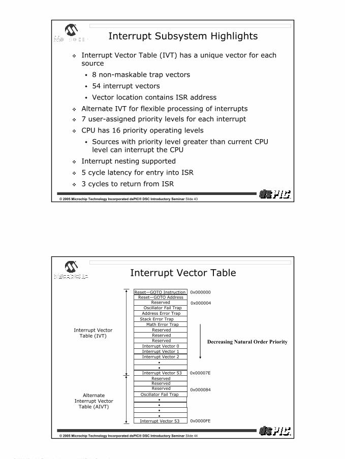
Interrupt Subsystem Highlights
Interrupt Vector Table (IVT) has a unique vector for each source
8 non-maskable trap vectors
54 interrupt vectors
Vector location contains ISR address
Alternate IVT for flexible processing of interrupts
7 user-assigned priority levels for each interrupt
CPU has 16 priority operating levels
Sources with priority level greater than current CPU level can interrupt the CPU
Interrupt nesting supported
5 cycle latency for entry into ISR
3 cycles to return from ISR
© 2005 Microchip Technology Incorporated dsPIC® DSC Introductory Seminar Slide 44
Reset—GOTO AddressReserved
Address Error TrapStack Error Trap
Math Error TrapReservedReservedReserved
Oscillator Fail Trap
Interrupt Vector 0 Interrupt Vector 1 Interrupt Vector 2
••
Interrupt Vector 53 Reserved
0x000000
0x000084
0x0000FE
Interrupt Vector Table (IVT)
0x000004
Reset—GOTO Instruction
Reserved
0x00007E
Oscillator Fail Trap
Interrupt Vector 53
••••
Alternate Interrupt Vector
Table (AIVT)
Decreasing Natural Order Priority
Interrupt Vector Table
Reserved

dsPIC® DSC Introductory Seminar
© 2004, Microchip Technology Incorporated, All Rights Reserved.
23
© 2005 Microchip Technology Incorporated dsPIC® DSC Introductory Seminar Slide 45
Knowledge Check #3
Interrupt Entry Latency is?
A: 5 cycles
B: No need for interrupts, service in foreground
C: 3 cycles
D: 167 ns @ 30 MIPS
E: Answer A and D
Bonus Question: Do traps have a higher natural priority relative to normal interrupts?
A: Yes
B: No
C: In most cases
© 2005 Microchip Technology Incorporated dsPIC® DSC Introductory Seminar Slide 46
Traps for Robust Operation
Oscillator Failure Trap (level 14)
Address Error Trap (level 13)
Instruction fetch from illegal program space
Data fetch from unimplemented data space
Unaligned word access from data space
Stack Error Trap (level 12)
Stack overflow or underflow
Arithmetic Error Trap (level 11)
Divide by Zero
Unsaturated Accumulator Overflow (A or B)
Catastrophic Accumulator Overflow (either)
Accumulator Shift Overflow

dsPIC® DSC Introductory Seminar
© 2004, Microchip Technology Incorporated, All Rights Reserved.
24
© 2005 Microchip Technology Incorporated dsPIC® DSC Introductory Seminar Slide 47
DSP Engine
© 2005 Microchip Technology Incorporated dsPIC® DSC Introductory Seminar Slide 48
DSP Engine Block Diagram
40-bit Accumulator A
40-bit Accumulator B
Adder
Saturate
Negate
Sign Extend
17-bit Multiplier/Scaler
Operand Pre-processing
Zer
o-b
ackf
ill
Round L
ogic
Satu
rate
Bar
rel
Shi fte
r
From W Array
X D
ata
Bu
s
Enable
16
40
16
16
3233
40
40
40
To W Array
16 16
Key Modules:
17x17-bit Multiplier / Scaler
Sign Extend / Zero Backfill Logic
40-bit Adder and two Accumulators
Rounding and Saturation Logic
40-bit Barrel Shifter

dsPIC® DSC Introductory Seminar
© 2004, Microchip Technology Incorporated, All Rights Reserved.
25
© 2005 Microchip Technology Incorporated dsPIC® DSC Introductory Seminar Slide 49
DSP Features
There is a set of special DSP instructions included in dsPIC®
DSC that speed processing of the typical mathematic calculations used in filters, control loops and more
MAC instruction—Multiply and Accumulate
Also Multiply and Subtract, Square and Accumulate, etc.
19 special DSP instructions total
MULTIPLY, DIVIDE and bit shift instructions
REPEAT instruction—repeats an instruction many times
DO instruction—repeats a block of instructions many times
With DSP instructions, this complex equation can be computed using only 2 instruction words and 5 instruction cycles!
[ ] [ ] [ ] [ ] [ ]321 3210 −+−+−+= nxbnxbnxbnxbny
© 2005 Microchip Technology Incorporated dsPIC® DSC Introductory Seminar Slide 50
Single Cycle MAC Instruction
Sample Instruction SyntaxMAC W4*W5, A, [W8]+=2, W4, [W10]-=6, W5, W13
Optional Arguments
Source operand registers
X prefetch source
Y prefetch source
X prefetch
destination
Y prefetch
destinationDestination accumulator
Other Acc.Write-backdestination
Basic Syntax
FIR Filter Tap = 1 instruction cycle (33 ns)

dsPIC® DSC Introductory Seminar
© 2004, Microchip Technology Incorporated, All Rights Reserved.
26
© 2005 Microchip Technology Incorporated dsPIC® DSC Introductory Seminar Slide 51
Special DSP Features
How does dsPIC® DSC assist real time processing?30 MIPS—up to 30 million calculations per secondPowerful instructions do many operations at the same time
Example: MAC instructionGets 2 data values from memoryMultiplies them togetherAdds the result to the accumulator
What does dsPIC® DSC have to help with high precision calculations?
The working registers of dsPIC DSC are all 16-bitsThe dsPIC DSC does 32-bit multiply and 32-bit divideThe dsPIC DSC has two 40-bit accumulators for calculation resultsSpecial instructions allow simple transfers of 16- and 32-bit data
© 2005 Microchip Technology Incorporated dsPIC® DSC Introductory Seminar Slide 52
Special Addressing Modes
DSP calculations involve a lot of data words. dsPIC® DSC has special addressing modes that help
Modulo addressing – scans through a block of data
Bit reversed addressing – needed by Fast Fourier Transform (FFT) calculation software
16-bit and 32-bit data move operations
DSP calculations also need to adjust the values of the data —this can be termed “scaling”.
dsPIC DSC has two 40-bit accumulators and automatic scaling of data on reads and writes for each

dsPIC® DSC Introductory Seminar
© 2004, Microchip Technology Incorporated, All Rights Reserved.
27
© 2005 Microchip Technology Incorporated dsPIC® DSC Introductory Seminar Slide 53
Knowledge Check #4
Super Bonus Question:
What is this equation used for?
What is it called?
[ ] [ ] [ ] [ ] [ ]321 3210 −+−+−+= nxbnxbnxbnxbny
This equation represents a digital filter
Finite Impulse Response (FIR) Filter
© 2005 Microchip Technology Incorporated dsPIC® DSC Introductory Seminar Slide 54
Normalized Cycle-Count ComparisonUsing BDTI Benchmarks
BDTI
Benchmark Results
Microchip dsPIC
30Fxxx* TI
C24x/C24xx
Motorola 56F83xx (56800E)
ADI 2199x (219x)
Vector Dot Product Real Block FIR Two Bi-Quad IIR Control**
1.00 1.00 1.00 1.00
1.16 1.32 2.12 2.05
1.07 1.11 1.29 2.06
1.32 1.02 1.47 1.76
* Projected Results ** Optimized for memory use; all other benchmarks optimized for speed.
Results © 2005 Berkeley Design Technology, Inc.
Contact [email protected] for info.
DSP Performance Benchmark

dsPIC® DSC Introductory Seminar
© 2004, Microchip Technology Incorporated, All Rights Reserved.
28
© 2005 Microchip Technology Incorporated dsPIC® DSC Introductory Seminar Slide 55
Normalized Execution-Time ComparisonUsing BDTI Benchmarks (Lower is Better)
BDTI
Benchmark Results
Microchip dsPIC
30Fxxx* (30 MIPS)
TI C24x/C24xx
(40 MIPS)
Motorola
56F83xx (56800E) (60 MIPS)
ADI 2199x (219x) (160 MIPS)
Vector Dot Product Real Block FIR Two-Biquad IIR Control**
1.00 1.00 1.00 1.00
0.87 0.99 1.59 1.54
0.53 0.55 0.65 1.03
0.25 0.19 0.28 0.33
* Projected Results ** Optimized for memory use; all other benchmarks optimized for speed.
DSP Performance Benchmark
Results © 2005 Berkeley Design Technology, Inc.Contact [email protected] for info.
© 2005 Microchip Technology Incorporated dsPIC® DSC Introductory Seminar Slide 56
Normalized Memory-Use ComparisonUsing BDTI Benchmarks (Lower is Better)
BDTI
Benchmark Results
Microchip dsPIC
30Fxxx*
TI C24x/C24xx
Motorola
56F83xx (56800E)
ADI 2199x (219x)
Control
1.00
1.30
0.85
1.44
* Projected Results
BDTI
Benchmark Results
Microchip dsPIC
30Fxxx*
TI C24x/C24xx
Motorola
56F83xx (56800E)
ADI 2199x (219x)
Control
1.00
1.30
0.85
1.44
* Projected Results
DSP Performance Benchmark
Results © 2004 Berkeley Design Technology, Inc.Contact [email protected] for info.

dsPIC® DSC Introductory Seminar
© 2004, Microchip Technology Incorporated, All Rights Reserved.
29
© 2005 Microchip Technology Incorporated dsPIC® DSC Introductory Seminar Slide 57
System Management Features
© 2005 Microchip Technology Incorporated dsPIC® DSC Introductory Seminar Slide 58
System Management Features
dsPIC® DSC has the same system management features that PIC® MCU users love:
♥Configurable Watchdog Timer with its own RC oscillatorProgrammable Time out: 2 ms—16 sec
♥Power-on Reset with a programmable delay 0, 4, 16, 64 ms
♥Brown-out Reset with programmable levels
♥Low VDD Detect Interrupt with programmable levels

dsPIC® DSC Introductory Seminar
© 2004, Microchip Technology Incorporated, All Rights Reserved.
30
© 2005 Microchip Technology Incorporated dsPIC® DSC Introductory Seminar Slide 59
Clock sources
XTL, XT, HSPrimaryXtal OSC
Clock Divide By
1, 4, 16, 64
32 KHzTimer1 Xtal
OSC
SystemClock
Fast RC 7.37 MHz
Low Pwr RC 512 kHz
EC Clock
SOSCI
SOSCO
OSC1
OSC2
PLL4x,8x,16x
or bypass
Includes 2 internal RC oscillators
Primary oscillator for crystals
PLL multiplies oscillator source for high frequency operationClock divide can optionally slow clock to conserve power
32 kHz for teal time clock
© 2005 Microchip Technology Incorporated dsPIC® DSC Introductory Seminar Slide 60
Power Control in dsPIC® DSC
How do I manage the dsPIC DSC power consumption?
dsPIC DSC PWRSAV Instruction provides 2 power-down modes, Sleep and Idle
Sleep mode stops core and all peripherals
Idle mode stops core and ...
Optionally stops peripherals
Peripherals interrupt will wake-up device
Dynamic PLL mode switching
Run-Time input clock divide

dsPIC® DSC Introductory Seminar
© 2004, Microchip Technology Incorporated, All Rights Reserved.
31
© 2005 Microchip Technology Incorporated dsPIC® DSC Introductory Seminar Slide 61
Fail-Safe Operation
Features that make the target system safe!
Clock monitor detects oscillator failure
Automatic switch to an internal RC clock
Illegal Program Instruction
Device resets
Traps let software handle error conditions
Oscillator failAddress out-of-rangeStack out-of-rangeMath errors
© 2005 Microchip Technology Incorporated dsPIC® DSC Introductory Seminar Slide 62
Knowledge Check #5
Your application needs to run at 30 MIPS. How can the oscillator circuit be configured?
A: Use the Fast RC oscillator
B: Use the XT oscillator and the x16 PLL
C: Use the Internal 7.37 MHz Fast RC Oscillator and the x16 PLL
The system needs to minimize power, but receive a character from the UART. Which power saving state should the dsPIC® DSC be in?
A: Sleep mode
B: Comatose mode
C: Idle mode
D: UART mode

dsPIC® DSC Introductory Seminar
© 2004, Microchip Technology Incorporated, All Rights Reserved.
32
© 2005 Microchip Technology Incorporated dsPIC® DSC Introductory Seminar Slide 63
Seminar Agenda
Session Time
Corporate Overview 9:00—9:15am
Architecture 9:15—10:30am
Break 10:30—10:45am
MPLAB® VDI Demonstration 10:45—11:15am
Peripherals 11:15—11:50am
Live Demonstrations 11:50—12:30pm
Lunch 12:30—1:30pm
Software/Hardware Tools 1:30—1:50pm
Hands-on 1:50—2:50pm
Libraries/Applications 2:50—3:15pm
Session Wrap-up 3:15—3:30pm
© 2005 Microchip Technology Incorporated dsPIC® DSC Introductory Seminar Slide 64
MPLAB® Visual Device Initializer (VDI)
Getting the dsPIC30F2010 Initialized with MPLAB VDI

dsPIC® DSC Introductory Seminar
© 2004, Microchip Technology Incorporated, All Rights Reserved.
33
© 2005 Microchip Technology Incorporated dsPIC® DSC Introductory Seminar Slide 65
MPLAB® VDI—Overview
Quick configuration of CPU and peripherals with resource conflict checks
Generates code for peripheral initialization
Readily extensible to other families and variants
Currently supports:PIC18C242, PIC18C252, PIC18C442, PIC18C452PIC18F2420, PIC18F2520, PIC18F2525, PIC18F2620, PIC18F4420, PIC18F4520, PIC18F4525, PIC18F4620PIC18F4680PIC18F6520, PIC18F6620, PIC18F6720, PIC18F8520, PIC18F8620, PIC18F8720dsPIC30F2010, dsPIC30F2011, dsPIC30F2012, dsPIC30F3010, dsPIC30F3011, dsPIC30F3012, dsPIC30F3013, dsPIC30F3014, dsPIC30F4011, dsPIC30F4012, dsPIC30F4013, dsPIC30F5011, dsPIC30F5013, dsPIC30F5015, dsPIC30F5016dsPIC30F6010, dsPIC30F6011, dsPIC30F6012, dsPIC30F6013, dsPIC30F6014, dsPIC30F6015dsPIC30F6010A, dsPIC30F6011A, dsPIC30F6012A, dsPIC30F6013A, dsPIC30F6014AComing soon: PIC16F785
© 2005 Microchip Technology Incorporated dsPIC® DSC Introductory Seminar Slide 66
Drag and drop operation
Context (right-click) menus
Feature configuration
Error (also reflected in Output window)
Zoom (shows pin allocation and signal direction)
One-click configuration of individual modules
Clicking on a module opens configuration dialog
MPLAB® VDI—Device Configuration

dsPIC® DSC Introductory Seminar
© 2004, Microchip Technology Incorporated, All Rights Reserved.
34
© 2005 Microchip Technology Incorporated dsPIC® DSC Introductory Seminar Slide 67
VDI is built into the MPLAB menu system as a plug-in (under Tools menu)
Code generation
Generates a C-callable assembly function
Uses ASM30 syntax for dsPIC30F
Uses MPASM syntax for PIC18XXX
Generates a C header file and an assembly include file
Project aware
Generated code written to project directory, automatically included in project
MPLAB® VDI—Integration into MPLAB Project
© 2005 Microchip Technology Incorporated dsPIC® DSC Introductory Seminar Slide 68
Pin mouse-over
Shows pin number, functions and selection
Allocates resources for ICSP™ programming/ICD, if needed
Device package selection (if others are available)
Support Information
VDI Report Generation
Separate reports for interrupts, pins and SFRs
Spawns Acrobat for Data Sheet and Errata
MPLAB® VDI—Other Features

dsPIC® DSC Introductory Seminar
© 2004, Microchip Technology Incorporated, All Rights Reserved.
35
© 2005 Microchip Technology Incorporated dsPIC® DSC Introductory Seminar Slide 69
MPLAB® IDE
User-friendly interface for editing, compiling, programming and debugging code
Color-coded source editor
Includes free assembler, linker and simulator
Support for several programming tools
MPLAB ICD 2, PRO MATE® II, PM3, MPLAB ICE-4000
C source level debugging
Supports third party tools
MPLAB Visual Device Initializer (VDI) support
© 2005 Microchip Technology Incorporated dsPIC® DSC Introductory Seminar Slide 70
MPLAB® VDI—Demo 1
See Appendix A
Getting your dsPIC® DSC Initialized with MPLAB VDI

dsPIC® DSC Introductory Seminar
© 2004, Microchip Technology Incorporated, All Rights Reserved.
36
© 2005 Microchip Technology Incorporated dsPIC® DSC Introductory Seminar Slide 71
Seminar Agenda
Session Time
Corporate Overview 9:00—9:15am
Architecture 9:15—10:30am
Break 10:30—10:45am
MPLAB® VDI Demonstration 10:45—11:15am
Peripherals 11:15—11:50am
Live Demonstrations 11:50—12:30pm
Lunch 12:30—1:30pm
Software/Hardware Tools 1:30—1:50pm
Hands-on 1:50—2:50pm
Libraries/Applications 2:50—3:15pm
Session Wrap-up 3:15—3:30pm
© 2005 Microchip Technology Incorporated dsPIC® DSC Introductory Seminar Slide 72
dsPIC30F Advanced Peripherals

dsPIC® DSC Introductory Seminar
© 2004, Microchip Technology Incorporated, All Rights Reserved.
37
© 2005 Microchip Technology Incorporated dsPIC® DSC Introductory Seminar Slide 73
dsPIC30F Peripheral Summary
Analog Peripherals
10-bit A/D Converter
12-bit A/D Converter
Digital Peripherals
16-bit Timers (5)
Input Capture (8)
Output Compare (8)
Quadrature Encoder Interface
Motor Control PWM
Communication
UART (2)
SPI™ (2)
I2C™
Audio Codec Interface
CAN (2)
dsPIC30F has advanced peripherals for advanced applications
© 2005 Microchip Technology Incorporated dsPIC® DSC Introductory Seminar Slide 74
dsPIC30F Advanced Peripherals
A/D Converters
10- or 12-bit
High-speed, Multi-channel

dsPIC® DSC Introductory Seminar
© 2004, Microchip Technology Incorporated, All Rights Reserved.
38
© 2005 Microchip Technology Incorporated dsPIC® DSC Introductory Seminar Slide 75
Feature Summary
Two A/D’s available on dsPIC® DSC depending on device family
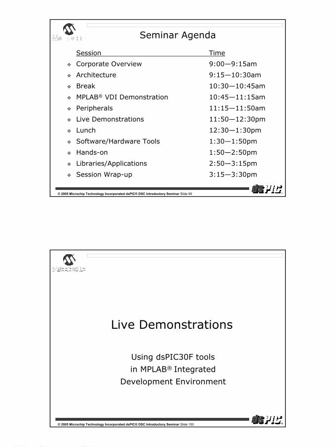
10-bit A/D10-bit resolution with ± 1-bit accuracySample time—84 ns (typ.)1 µsec/1Msps conversion timeUp to 16 analog inputs, 4 S/H amplifiers
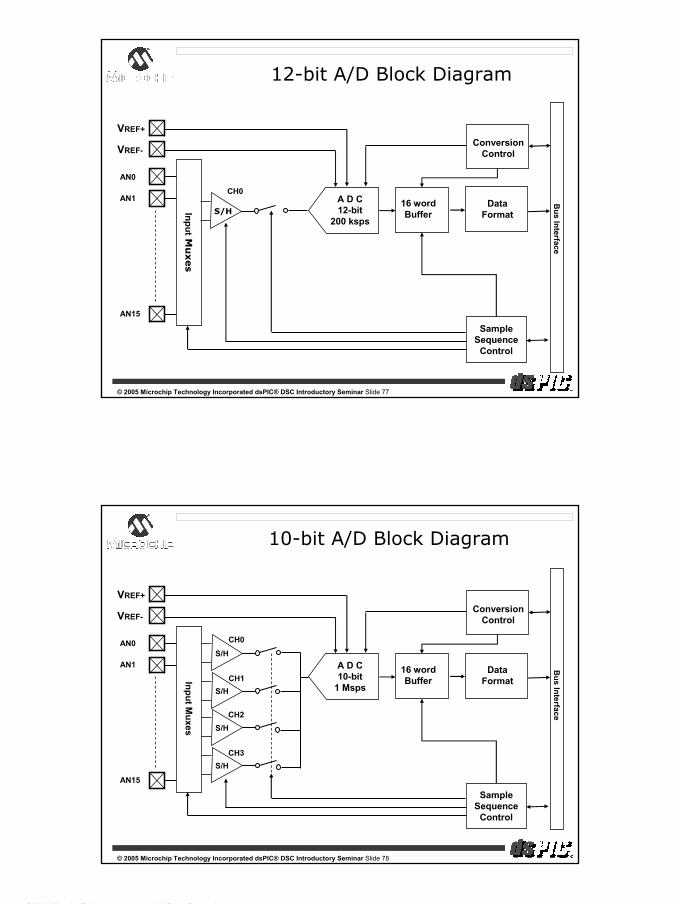
12-bit A/D 12-bit resolution with ± 1-bit accuracySample time—334 ns (typ.)5 µsec/200 ksps conversion timeUp to 16 analog inputs, 1 S/H amplifiers
© 2005 Microchip Technology Incorporated dsPIC® DSC Introductory Seminar Slide 76
Common Feature Summary
External VREF+ and VREF-
Analog Input Range: (VREF-) to (VREF+)
Allows uni-polar differential measurements
Reject common mode noise
Programmable sampling sequence
16 sample, dual-ported result buffer
Scan mode
Alternate sample mode
Multiple conversion trigger sources
Selectable result formats
Conversions in Sleep and Idle modes
dsPIC® DSC Introductory Seminar
© 2004, Microchip Technology Incorporated, All Rights Reserved.
39
© 2005 Microchip Technology Incorporated dsPIC® DSC Introductory Seminar Slide 77
12-bit A/D Block Diagram
VREF+
VREF-
A D C12-bit
200 ksps
ConversionControl
Bus Interface
DataFormat
16 wordBuffer
SampleSequence
Control
InputM
uxes
AN0
AN1S/H
AN15
CH0
© 2005 Microchip Technology Incorporated dsPIC® DSC Introductory Seminar Slide 78
10-bit A/D Block Diagram
VREF+
VREF-
A D C10-bit
1 Msps
ConversionControl
Bus Interface
DataFormat
16 wordBuffer
SampleSequence
Control
Input Muxes
AN0
AN1S/H
S/H
S/H
S/H
AN15
CH0
CH1
CH2
CH3

dsPIC® DSC Introductory Seminar
© 2004, Microchip Technology Incorporated, All Rights Reserved.
40
© 2005 Microchip Technology Incorporated dsPIC® DSC Introductory Seminar Slide 79
Multi-Channel Sampling
10-bit A/D has 4 Sample/Hold amplifiers
Enable 1, 2, or 4 per conversion sequence
Simultaneous sample, then convert OR
Sequentially sample
AN0
AN1
AN2
AN3
SIMULTANEOUSSAMPLING
SEQUENTIALSAMPLING
AN0
AN1
AN2
AN3
SIMULTANEOUSSAMPLING
SEQUENTIALSAMPLING
© 2005 Microchip Technology Incorporated dsPIC® DSC Introductory Seminar Slide 80
Knowledge Check #6
You need to oversample a 50 kHz signal by 10x. Which ADC module can you use?
A: 12-bit ADC
B: 10-bit ADC
C: Both
Which ADC module supports scanning mode?
A: 10-bit ADC
B: 12-bit ADC
C: Answer A only
D: Answer A and B

dsPIC® DSC Introductory Seminar
© 2004, Microchip Technology Incorporated, All Rights Reserved.
41
© 2005 Microchip Technology Incorporated dsPIC® DSC Introductory Seminar Slide 81
dsPIC30F Advanced Peripherals
Motor Control PWM
Comprehensive Motor Drive
© 2005 Microchip Technology Incorporated dsPIC® DSC Introductory Seminar Slide 82
Motor PWM Feature Summary
Need an inverter control solution for ACIM, BLDC, SR motors?
Dedicated 16-bit timebase
Four PWM generators
Each PWM generator drives a pair of I/O pins
I/O can be complementary or independent
Center or edge aligned PWM
Programmable output polarity for I/O
Dead time unit prevents power shoot-through
Manual override control for motor commutation
2 fault pins control outputs without software
Programmable shutdown state
Two operating modes

dsPIC® DSC Introductory Seminar
© 2004, Microchip Technology Incorporated, All Rights Reserved.
42
© 2005 Microchip Technology Incorporated dsPIC® DSC Introductory Seminar Slide 83
Motor Control PWM Block Diagram
Four PWM output pairs with output polarity
control
Duty Cycle
Generator #3
Duty Cycle
Generator #2
Duty Cycle
Generator #1
Duty Cycle
Generator #4
PWM Override Logic
Dead Time Unit
Dead Time Unit
Dead Time Unit
Dead Time Unit
Fault A
Fault B
PWM4H
PWM1L
PWM1H
PWM2L
PWM2H
PWM3L
PWM3H
PWM4L
Two fault pins w/ programmable
fault states
16-bit Time Base
A/D Conversion Trigger
Dead Time B
Dead Time AOverride Control
© 2005 Microchip Technology Incorporated dsPIC® DSC Introductory Seminar Slide 84
Motor Control PWM
Independent mode used for switched reluctance motor
Special inverter circuit to control current in SR motors
Independent mode enables both devices to turn on
+V
PWM1H
PWM1L
PWM2H
PWM2L
PWM3H
PWM3L
PWM4H
PWM4L

dsPIC® DSC Introductory Seminar
© 2004, Microchip Technology Incorporated, All Rights Reserved.
43
© 2005 Microchip Technology Incorporated dsPIC® DSC Introductory Seminar Slide 85
Motor Control PWM
Complementary mode used for 3-Phase AC Motor
Dead time avoids shoot through
+V
PWM1H
PWM1L
3 PhaseACIM
PWM2H
PWM2L
PWM3H
PWM3L
© 2005 Microchip Technology Incorporated dsPIC® DSC Introductory Seminar Slide 86
Dead Time A Dead Time B
PWM1H
PWM1L
PWM1H
PWM1L
MCPWM Dead Time Insertion
Use in Complementary mode
Two programmable dead times
One dead time per pair for multiple inverters OR
Two dead times per pair for distortion optimization
33 nsec minimum resolution, up to 10 µsec

dsPIC® DSC Introductory Seminar
© 2004, Microchip Technology Incorporated, All Rights Reserved.
44
© 2005 Microchip Technology Incorporated dsPIC® DSC Introductory Seminar Slide 87
MCPWM A/D Synchronization
SEVTCMP register sets A/D conversion start time in PWM cycle
Ensure A/D properly captures shunt current
Can also used to minimize control loop update delay
To A/D
PWM1LPWM1H
PWM1H
PWM1L
Trigger conversion at end of bottom transistor on-time
T
© 2005 Microchip Technology Incorporated dsPIC® DSC Introductory Seminar Slide 88
Knowledge Check #7
How many PWM outputs does the MC PWM peripheral support?
A: 4 complementary pairs
B: 8 independent pins
C: Answer A and B
Dead-time insertion may be implemented to prevent “shoot-through” for which PWM mode?
A: Independent mode
B: Overworked mode
C: Complementary mode
D: Answer A and C

dsPIC® DSC Introductory Seminar
© 2004, Microchip Technology Incorporated, All Rights Reserved.
45
© 2005 Microchip Technology Incorporated dsPIC® DSC Introductory Seminar Slide 89
dsPIC30F Advanced Peripherals
Quadrature Encoder Interface
Motion Control Feedback Peripheral
© 2005 Microchip Technology Incorporated dsPIC® DSC Introductory Seminar Slide 90
Incremental Encoders

dsPIC® DSC Introductory Seminar
© 2004, Microchip Technology Incorporated, All Rights Reserved.
46
© 2005 Microchip Technology Incorporated dsPIC® DSC Introductory Seminar Slide 91
Encoder Timing Diagram
+1 +1+1 +1 +1 +1 +1 +1 +1 +1 +1 +1 +1 +1 +1 +1 -1 -1 -1 -1 -1 -1 -1 -1 -1 -1 -1 -1 -1 -1 -1COUNT
PHASE A
PHASE B
State machine determines relative phase at each edge
© 2005 Microchip Technology Incorporated dsPIC® DSC Introductory Seminar Slide 92
Quadrature Encoder Interface
Hardware to assist in calculations of position and speed?
Three Input Quadrature Encoder Interface
Two inputs for Phase A and Phase B signals
Index pulse input (output from encoder)
16-bit position counter
Rollover count register (MAXCNT) simplifies RPM detection
Module may function as 16-bit Up/down Timer
Digital noise filter on all inputs

dsPIC® DSC Introductory Seminar
© 2004, Microchip Technology Incorporated, All Rights Reserved.
47
© 2005 Microchip Technology Incorporated dsPIC® DSC Introductory Seminar Slide 93
dsPIC30F Advanced Peripherals
Data Converter Interface (DCI)
Audio Interface Peripheral
© 2005 Microchip Technology Incorporated dsPIC® DSC Introductory Seminar Slide 94
DCI Applications
Digital interface for higher quality audio & speech
Typical sample rate, 8 to 48 kHz
Typical codec word size 13 to > 24 bits
Modem/telephony
Musical instrument effects
Speech recognition
Speech/audio compression
Echo cancellation
Consumer-quality audio
AC Power Quality Analyzer

dsPIC® DSC Introductory Seminar
© 2004, Microchip Technology Incorporated, All Rights Reserved.
48
© 2005 Microchip Technology Incorporated dsPIC® DSC Introductory Seminar Slide 95
Codec Communication
DCI designed for continuous, streaming data
Works like SPI™, but SCK is continuous
Streaming data is organized into frames
TDM data slots
Multiple data words can be transferred
Specific data assigned to a “timeslot”
Frame Sync (FS) signal marks the frame
FS starts a data transfer
FS usually occurs at the audio sample rate
© 2005 Microchip Technology Incorporated dsPIC® DSC Introductory Seminar Slide 96
Multi-channel (Slot) Timing
MSB LSB MSB LSB MSB MSBLSB LSB
SCK
FS
Data
Timeslot 0 Timeslot 1 Timeslot 2 Timeslot n
MSB LSB MSB
SCK
FS
Data
Single Word Transfer
Multiple Word Transfer

dsPIC® DSC Introductory Seminar
© 2004, Microchip Technology Incorporated, All Rights Reserved.
49
© 2005 Microchip Technology Incorporated dsPIC® DSC Introductory Seminar Slide 97
DCI Features
Automatic synchronous serial data transfer
TDM features support up to 16 data timeslots
Automatic slot management
Module has up to 4 word buffer (16-bit words)
Master or slave operation
Separate baud generator for SCK signal
Support for I2S (Inter-IC Sound) and AC’97 protocols
© 2005 Microchip Technology Incorporated dsPIC® DSC Introductory Seminar Slide 98
I2S Protocol
MSB LSB MSB LSB
COFS
CSDx
Left Channel Right Channel
Philips specification (Inter-IC Sound)
Common interface for high fidelity 2 channel stereo codecs
FS has 50% duty cycle
FS edge initiates transfer of appropriate channel
dsPIC® DSC Introductory Seminar
© 2004, Microchip Technology Incorporated, All Rights Reserved.
50
© 2005 Microchip Technology Incorporated dsPIC® DSC Introductory Seminar Slide 99
Seminar Agenda
Session Time
Corporate Overview 9:00—9:15am
Architecture 9:15—10:30am
Break 10:30—10:45am
MPLAB® VDI Demonstration 10:45—11:15am
Peripherals 11:15—11:50am
Live Demonstrations 11:50—12:30pm
Lunch 12:30—1:30pm
Software/Hardware Tools 1:30—1:50pm
Hands-on 1:50—2:50pm
Libraries/Applications 2:50—3:15pm
Session Wrap-up 3:15—3:30pm
© 2005 Microchip Technology Incorporated dsPIC® DSC Introductory Seminar Slide 100
Live Demonstrations
Using dsPIC30F tools
in MPLAB® Integrated
Development Environment

dsPIC® DSC Introductory Seminar
© 2004, Microchip Technology Incorporated, All Rights Reserved.
51
© 2005 Microchip Technology Incorporated dsPIC® DSC Introductory Seminar Slide 101
Built-InEditor
ProjectManager
Source LevelDebug
OpenInterface
MPLAB IDEIntegrated Development Environment
AssemblerSoftwareSimulator
RTOSOSEK
LinkerLibrarian
MPLAB C30Compiler
MPLAB ICD 2In-Circuit Debugger
MPLABICE 4000 MPLAB PM3
CompilersIAR, HiTech
ApplicationLibraries
Languages Low costDebugging
Emulation DeviceProgramming
3rd partyTools
© 2005 Microchip Technology Incorporated dsPIC® DSC Introductory Seminar Slide 102
MPLAB® C30 C Compiler
dsPIC® DSC Introductory Seminar
© 2004, Microchip Technology Incorporated, All Rights Reserved.
52
© 2005 Microchip Technology Incorporated dsPIC® DSC Introductory Seminar Slide 103
MPLAB® C30 Compiler
GNU-based
Assembler, linker and librarian included
ANSI C compliant, with standard libraries
Optimized for dsPIC® DSC architectural features
Utilizes advanced addressing modes
Efficient multi-bit shift operations
Efficient signed/unsigned comparisons
Flexible memory usage models
Support for constants stored in program memory
© 2005 Microchip Technology Incorporated dsPIC® DSC Introductory Seminar Slide 104
Compiler supports 5 levels of code optimization
-O1, -O2, -O3, -Os, and no optimization
Optional Loop Unrolling
Replacing loops with repeated code, to reduce execution time
Optional Procedural Abstraction
Combining similar pieces of code into common functions, to reduce code size
Compiler Optimization

dsPIC® DSC Introductory Seminar
© 2004, Microchip Technology Incorporated, All Rights Reserved.
53
© 2005 Microchip Technology Incorporated dsPIC® DSC Introductory Seminar Slide 105
Code size examples for different optimization levels for a brushless DC motor control application
No optimization: 19584 bytes
Loop Unrolling only: 14031 bytes
Optimization Level 1 (-O1): 14361 bytes
Optimization Level 2 (-O2): 12096 bytes
Optimization Level 3 (-O3): 17292 bytes
Optimization for Size (-Os): 13632 bytes
See Application Note AN901 (v1.00)MPLAB C30 v1.31.00
Compiler Optimization
© 2005 Microchip Technology Incorporated dsPIC® DSC Introductory Seminar Slide 106
Run-Time Startup
Executes before the application’s main( )
Initializes C framework
Initializes stack
Initializes constants
Initializes data memory
Calls the user’s “main” function
If no data memory needs to be initializedLink with the --no-data-init option
Saves 50 instruction words
dsPIC® DSC Introductory Seminar
© 2004, Microchip Technology Incorporated, All Rights Reserved.
54
© 2005 Microchip Technology Incorporated dsPIC® DSC Introductory Seminar Slide 107
MPLAB® IDE—Demo 2
See Appendix B
Getting started with dsPIC30F and MPLAB IDE
© 2005 Microchip Technology Incorporated dsPIC® DSC Introductory Seminar Slide 108
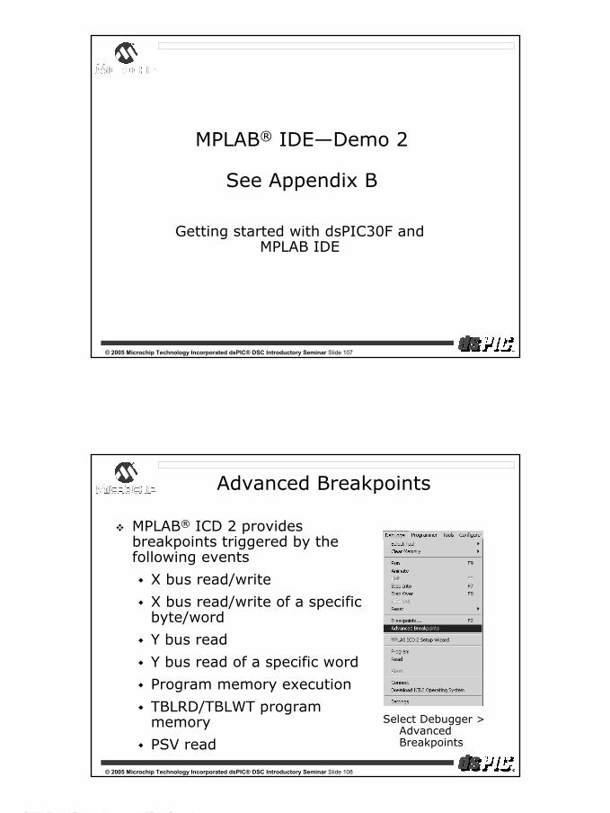
Advanced Breakpoints
MPLAB® ICD 2 provides breakpoints triggered by the following events
X bus read/write
X bus read/write of a specific byte/word
Y bus read
Y bus read of a specific word
Program memory execution
TBLRD/TBLWT program memory
PSV read
Select Debugger > Advanced Breakpoints
dsPIC® DSC Introductory Seminar
© 2004, Microchip Technology Incorporated, All Rights Reserved.
55
© 2005 Microchip Technology Incorporated dsPIC® DSC Introductory Seminar Slide 109
MPLAB® IDE—Demo 3
See Appendix C
Debugging an application with MPLAB ICD 2
© 2005 Microchip Technology Incorporated dsPIC® DSC Introductory Seminar Slide 110
What’s For LUNCH?
That’s what I’m talking about!

dsPIC® DSC Introductory Seminar
© 2004, Microchip Technology Incorporated, All Rights Reserved.
56
© 2005 Microchip Technology Incorporated dsPIC® DSC Introductory Seminar Slide 111
Seminar Agenda
Session Time
Corporate Overview 9:00—9:15am
Architecture 9:15—10:30am
Break 10:30—10:45am
MPLAB® VDI Demonstration 10:45—11:15am
Peripherals 11:15—11:50am
Live Demonstrations 11:50—12:30pm
Lunch 12:30—1:30pm
Software/Hardware Tools 1:30—1:50pm
Hands-on 1:50—2:50pm
Libraries/Applications 2:50—3:15pm
Session Wrap-up 3:15—3:30pm
© 2005 Microchip Technology Incorporated dsPIC® DSC Introductory Seminar Slide 112
dsPIC® DSC Software and Hardware Tools
Vital building blocks to get your application running
dsPIC® DSC Introductory Seminar
© 2004, Microchip Technology Incorporated, All Rights Reserved.
57
© 2005 Microchip Technology Incorporated dsPIC® DSC Introductory Seminar Slide 113
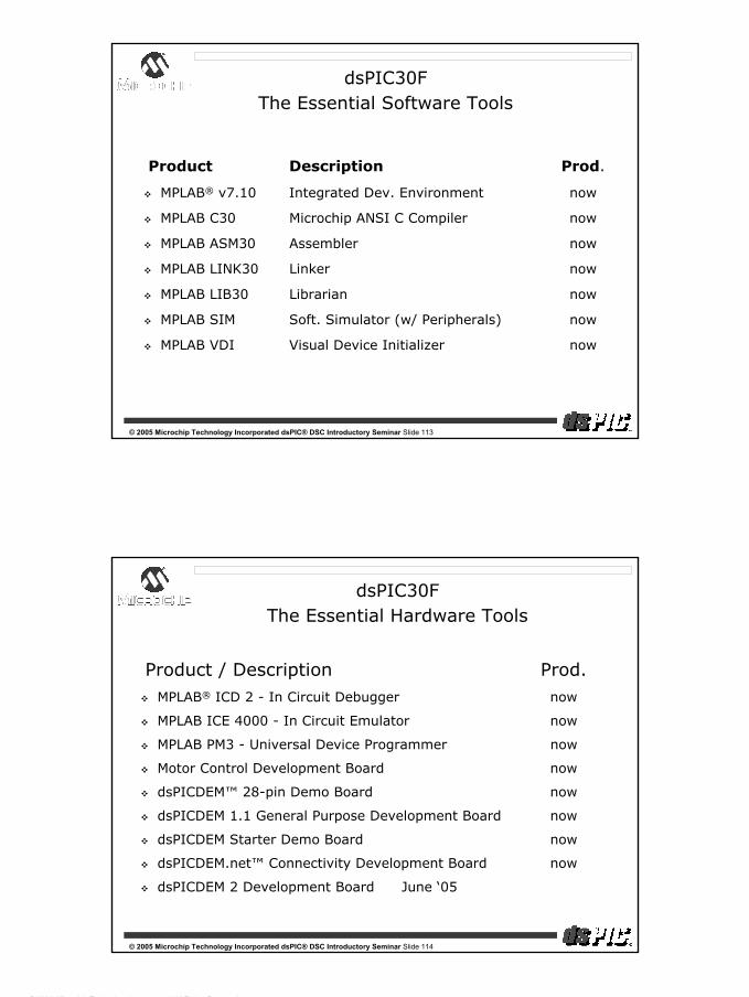
Product Description Prod.
MPLAB® v7.10 Integrated Dev. Environment now
MPLAB C30 Microchip ANSI C Compiler now
MPLAB ASM30 Assembler now
MPLAB LINK30 Linker now
MPLAB LIB30 Librarian now
MPLAB SIM Soft. Simulator (w/ Peripherals) now
MPLAB VDI Visual Device Initializer now
dsPIC30FThe Essential Software Tools
© 2005 Microchip Technology Incorporated dsPIC® DSC Introductory Seminar Slide 114
Product / Description Prod.MPLAB® ICD 2 - In Circuit Debugger now
MPLAB ICE 4000 - In Circuit Emulator now
MPLAB PM3 - Universal Device Programmer now
Motor Control Development Board now
dsPICDEM™ 28-pin Demo Board now
dsPICDEM 1.1 General Purpose Development Board now
dsPICDEM Starter Demo Board now
dsPICDEM.net™ Connectivity Development Board now
dsPICDEM 2 Development Board June ‘05
dsPIC30FThe Essential Hardware Tools

dsPIC® DSC Introductory Seminar
© 2004, Microchip Technology Incorporated, All Rights Reserved.
58
© 2005 Microchip Technology Incorporated dsPIC® DSC Introductory Seminar Slide 115
Application Development Platforms
© 2005 Microchip Technology Incorporated dsPIC® DSC Introductory Seminar Slide 116
dsPICDEM MC1 Development Board—DM300020
Full featured development board—US $299 retail
Excellent starting point for motor control-based applications
Example code with Documentation CD
Works with MPLAB® ICD 2 In-Circuit Debugger/Programmer
MPLAB ICE 4000 Emulator-ready
Supports AC Induction Motor (ACIM)
Supports Brushless DC (BLDC)
dsPICDEM™ MC1 Motor Control Development Board

dsPIC® DSC Introductory Seminar
© 2004, Microchip Technology Incorporated, All Rights Reserved.
59
© 2005 Microchip Technology Incorporated dsPIC® DSC Introductory Seminar Slide 117
Hall-effect sensor terminals to capture pins
Encoder input terminals to QEI
QEI direction status LED
Prototyping area
37-pin Interface to Power Module
16 x 2 LCD display
Potentiometers (2)
Buttons (4), plus PWM fault button
Power supply
MPLAB® ICD interface and comm. selection switch
RS-232 interface
CAN interface
RS-485 interface
LEDs (4)
dsPIC® DSC emulation header
Motor control test points
dsPICDEM™ MC1 Motor Control Development Board
© 2005 Microchip Technology Incorporated dsPIC® DSC Introductory Seminar Slide 118
dsPIC® DSC Motor Control Development Kit
3-Phase High Voltage Power Module
Input SourceConnections
Motor Connections(not shown)
Motor ControlDevelopment Board

dsPIC® DSC Introductory Seminar
© 2004, Microchip Technology Incorporated, All Rights Reserved.
60
© 2005 Microchip Technology Incorporated dsPIC® DSC Introductory Seminar Slide 119
ACIM Development Components
dsPICDEM™ MC1 Motor Control Development BoardDM300020—(US $299 retail)
dsPICDEM MC1H 3-Phase High Voltage Power ModuleDM300021—(US $800 retail)
3-Phase ACIM High Voltage Motor (208/460V)AC300021—(US $120 retail)
Comes with example software and documentation CD
© 2005 Microchip Technology Incorporated dsPIC® DSC Introductory Seminar Slide 120
BLDC Development Components
dsPICDEM™ MC1 Motor Control Development BoardDM300020—(US $299 retail)
dsPICDEM MC1L 3-Phase Low Voltage Power ModuleDM300022—(US $700 retail)
3-Phase BLDC Low Voltage Motor (24V)AC300020—(US $120 retail)
Comes with getting started documentation

dsPIC® DSC Introductory Seminar
© 2004, Microchip Technology Incorporated, All Rights Reserved.
61
© 2005 Microchip Technology Incorporated dsPIC® DSC Introductory Seminar Slide 121
dsPICDEM 28-pin Starter Demo Board—DM300017
Simple low-cost demo board—US $79 retail
Basic step-by-step getting started with dsPIC® DSC
Good starting point for 1st time user and beginners
Simple demo and source code provided exercising
Interrupts, UART, I/O
Complete User’s Guide available
Works with MPLAB® ICD 2 In-circuit Debugger/Programmer
dsPICDEM™ 28-pin Starter Demo Board
© 2005 Microchip Technology Incorporated dsPIC® DSC Introductory Seminar Slide 122
dsPICDEM™ 28-pin Starter Demo Board
UART
LED(1)
MPLAB® ICD 2 +9Vdc
ResetSwitch
XTAL
dsPIC® DSC
I/O PinHeader
PrototypingArea
Power-onLED
dsPIC® DSC Introductory Seminar
© 2004, Microchip Technology Incorporated, All Rights Reserved.
62
© 2005 Microchip Technology Incorporated dsPIC® DSC Introductory Seminar Slide 123
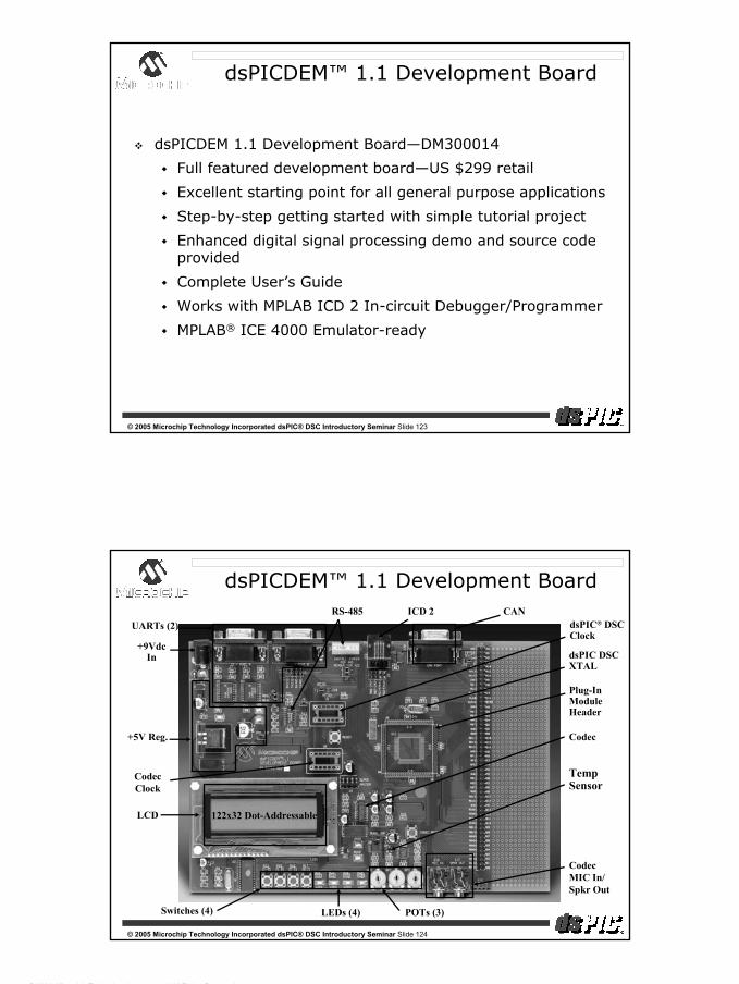
dsPICDEM 1.1 Development Board—DM300014
Full featured development board—US $299 retail
Excellent starting point for all general purpose applications
Step-by-step getting started with simple tutorial project
Enhanced digital signal processing demo and source code provided
Complete User’s Guide
Works with MPLAB ICD 2 In-circuit Debugger/Programmer
MPLAB® ICE 4000 Emulator-ready
dsPICDEM™ 1.1 Development Board
© 2005 Microchip Technology Incorporated dsPIC® DSC Introductory Seminar Slide 124
dsPICDEM™ 1.1 Development Board
LCD
CANUARTs (2)
RS-485 ICD 2
Switches (4) POTs (3)
CodecMIC In/Spkr Out
Plug-InModuleHeader
dsPIC DSCXTAL
Codec
LEDs (4)
+9VdcIn
TempSensor
+5V Reg.
dsPIC® DSCClock
122x32 Dot-Addressable
CodecClock

dsPIC® DSC Introductory Seminar
© 2004, Microchip Technology Incorporated, All Rights Reserved.
63
© 2005 Microchip Technology Incorporated dsPIC® DSC Introductory Seminar Slide 125
dsPICDEM™ Starter Demo Board
dsPICDEM Starter Demo Board (SDB)—DM300016
Simple low-cost demo board—US $79 retail/($209 w/ MPLAB® ICD 2)
Basic step-by-step getting started with dsPIC® DSC
Good starting point for first time user and beginners
Simple demo and source code provided
Complete User’s Guide available
Works with MPLAB ICD 2 In-circuit Debugger/Programmer
© 2005 Microchip Technology Incorporated dsPIC® DSC Introductory Seminar Slide 126
dsPICDEM™ Starter Demo Board
UART
Switches
LEDs
MPLAB® ICD 2
Low Pass Filter
+9Vdc
ResetSwitch
Digital Pot
Potentiometer
XTAL
Plug-inModule

dsPIC® DSC Introductory Seminar
© 2004, Microchip Technology Incorporated, All Rights Reserved.
64
© 2005 Microchip Technology Incorporated dsPIC® DSC Introductory Seminar Slide 127
dsPICDEM.net™ Connectivity Board
dsPICDEM.net Connectivity Board—DM300004-1/2
Full-featured Connectivity board—US $389 retail
Excellent starting point for connectivity-based applications
Step-by-step getting started with simple tutorial project
Enhanced demo project utilizing all board functions
Full C and assembly code provided
V.22bis Soft-Modem Demo—(full source code provided)
CMX-MicroNet WEB Server Demo—(.hex file)
CMX-MicroNet FTP Server Demo—(.hex file)
Complete and Comprehensive User’s Guide
MPLAB® ICD 2 and MPLAB ICE 4000 Emulator-ready
© 2005 Microchip Technology Incorporated dsPIC® DSC Introductory Seminar Slide 128
dsPICDEM.net™ Connectivity Board
PSTNInterface
10-Base TEthernetNIC
64Kx16SRAM
UART
LCD
CAN
CallProgressSpeaker
MPLAB® ICD 2RS-485
Plug-inModuleHeader
Switches (3)LEDs (3)POTs (2)
XTAL
TempSensor
+9VdcIn
24LC515
+5Vdc Reg.
2x16 Characters

dsPIC® DSC Introductory Seminar
© 2004, Microchip Technology Incorporated, All Rights Reserved.
65
© 2005 Microchip Technology Incorporated dsPIC® DSC Introductory Seminar Slide 129
dsPICDEM™ 2 General Purpose Development Board
Motor Control FamilydsPIC DSCs or
MPLAB ICE 4000 device adapter installed here
Sensor and General PurposeFamily dsPIC devices or
MPLAB ICE 4000 device adapter installed here
MPLAB® ICD 2 compatible
+9VdcIn
UART CAN
LCD 2x16 Characters
© 2005 Microchip Technology Incorporated dsPIC® DSC Introductory Seminar Slide 130
dsPICDEM 2 Demo Board — DM300018
Simple low-cost demo board - US $99 retail
Development platform for 11 dsPIC30F devices
18-, 28- and 40-pin packages
Motor Control, Sensor and General Purpose
MPLAB® ICD 2 and MPLAB ICE 4000 -ready
On-board CAN and UART support
Support for Multiple Oscillator options
C Example Code and User Guide provided
dsPICDEM™ 2 General Purpose Development Board
Available June

dsPIC® DSC Introductory Seminar
© 2004, Microchip Technology Incorporated, All Rights Reserved.
66
© 2005 Microchip Technology Incorporated dsPIC® DSC Introductory Seminar Slide 131
Desktop Tools
Windows®-based applications to assist you with your design
© 2005 Microchip Technology Incorporated dsPIC® DSC Introductory Seminar Slide 132
dsPIC® Digital Filter Design
What’s so great about digital filters?
More accuracy than analog filters
No age or temperature drift
Better phase response, frequency response
Simple to modify
Hardware doesn’t change—just coefficients!
Benefits of replacing analog filters
Fewer components
Less board space
Lower cost

dsPIC® DSC Introductory Seminar
© 2004, Microchip Technology Incorporated, All Rights Reserved.
67
© 2005 Microchip Technology Incorporated dsPIC® DSC Introductory Seminar Slide 133
dsPIC® Digital Filter Design
Graphically design all types of digital filters
Low-pass, high-pass
Band-pass, band-stop
Digital filter algorithm kernels are provided for:
FIR—Finite Impulse Response
IIR—Infinite Impulse Response
Designing coefficients to control the filter response is the tricky part
You can do the math or use this tool!!
Quickly observe filters response
Generated code and coefficients fully compatible with MPLAB® C30 C Compiler language tools
© 2005 Microchip Technology Incorporated dsPIC® DSC Introductory Seminar Slide 134
dsPIC® Digital Filter Design

dsPIC® DSC Introductory Seminar
© 2004, Microchip Technology Incorporated, All Rights Reserved.
68
© 2005 Microchip Technology Incorporated dsPIC® DSC Introductory Seminar Slide 135
dsPICWorks™ Data Analysis and DSP Software
Graphical signal analysis and generation tool
Create waveforms and process them
Signal generation
SIN, square, swept SIN, triangular, etc...
Signal operations
Add, Flip and Shift, Multiply, etc...
DSP operations
Filtering, correlation, FFT, LPC analysis, etc...
Designed especially for the dsPIC30F
Import/export data with MPLAB® compatible files
Processes filter files saved from dsPIC® Digital Filter Design
FREE
© 2005 Microchip Technology Incorporated dsPIC® DSC Introductory Seminar Slide 136
dsPICWorks™ Data Analysis and DSP Software

dsPIC® DSC Introductory Seminar
© 2004, Microchip Technology Incorporated, All Rights Reserved.
69
© 2005 Microchip Technology Incorporated dsPIC® DSC Introductory Seminar Slide 137
Seminar Agenda
Session Time
Corporate Overview 9:00—9:15am
Architecture 9:15—10:30am
Break 10:30—10:45am
MPLAB® VDI Demonstration 10:45—11:15am
Peripherals 11:15—11:50am
Live Demonstrations 11:50—12:30pm
Lunch 12:30—1:30pm
Software/Hardware Tools 1:30—1:50pm
Hands-on 1:50—2:50pm
Libraries/Applications 2:50—3:15pm
Session Wrap-up 3:15—3:30pm
© 2005 Microchip Technology Incorporated dsPIC® DSC Introductory Seminar Slide 138
Hands-on Session—Part 1
dsPIC® Digital Filter Design & dsPICworks™ Visual Algorithm Analyzer
Digital Filtering and DSP Simulations in a Jiffy!!

dsPIC® DSC Introductory Seminar
© 2004, Microchip Technology Incorporated, All Rights Reserved.
70
© 2005 Microchip Technology Incorporated dsPIC® DSC Introductory Seminar Slide 139
Hands-on Session—Objectives
Design a FilterUse dsPIC® Filter Design Lite
IIR band-stop filter specification:Sampling Rate = 11127 HzStop Band: 1200 Hz to 1250 HzStop Band Attenuation = 50 dB Pass Band: Up to 1000 Hz and > 1400 HzPass Band Ripple = 0.1 dB
Simulate Filter OperationUse dsPICworks™ Analyzer
Use the designed filter to remove 1225 Hz tone component from a WAV file
© 2005 Microchip Technology Incorporated dsPIC® DSC Introductory Seminar Slide 140
The Essential DSP Tools
dsPIC® DSC Digital Filter Design
Design optimal IIR and FIR filters
Band-pass, band-stop, high-pass and low-pass filters
Graphical user interface to further ease design
Plots and graphs include
Magnitude and phase response
Pole-zero plots on the unit circle
Impulse and step response
dsPIC DSC support
Filter coefficient and code generation

dsPIC® DSC Introductory Seminar
© 2004, Microchip Technology Incorporated, All Rights Reserved.
71
© 2005 Microchip Technology Incorporated dsPIC® DSC Introductory Seminar Slide 141
Digital Filter Design Lite
Digital Filter Design Tool available in two flavors:
Full-blown version
Lite version
Lite version provided with dsPIC® DSC Seminar Software
Get Started—Invoke our enLitened Filter Guru
from the Windows® Start Menu OR
“Start > Programs > MDS > dsPICfdlite”
click on the short-cut on your desktop
© 2005 Microchip Technology Incorporated dsPIC® DSC Introductory Seminar Slide 142
Digital Filter Design Lite
Click here to loadfilter specification file
Let’s load an existing filter specification file
Click on the SPC icon to load a specification file created for this demo

dsPIC® DSC Introductory Seminar
© 2004, Microchip Technology Incorporated, All Rights Reserved.
72
© 2005 Microchip Technology Incorporated dsPIC® DSC Introductory Seminar Slide 143
The Essential DSP Tools—Exercise 1
See Appendix D
Using Digital Filter Design Lite
© 2005 Microchip Technology Incorporated dsPIC® DSC Introductory Seminar Slide 144
The Essential DSP Tools
dsPICworks™ Analyzer: Data Analysis & DSP Software
Simulate complex DSP functions & mathematical expressions
Difference equations, scaling etc.
Digital Filters, FFT, Inverse-FFT etc.
Generate Signals
Sine, triangular, square etc.
Add noise to signals
Analyze data in frequency-domain
1-, 2- and 3-d FFT plots
Import/export capabilities

dsPIC® DSC Introductory Seminar
© 2004, Microchip Technology Incorporated, All Rights Reserved.
73
© 2005 Microchip Technology Incorporated dsPIC® DSC Introductory Seminar Slide 145
dsPICworks™ Analyzer: Filters in Action
A sample Windows® WAV file is provided to you<Your Path:\>dsPIC Seminar\Follow_Along\Part 1
WAV file has spurious tonal noise at 1225 Hz
You could listen to it on your PC!
We will now use dsPICworks Analyzer to
Import the WAV file
Run the data through the designed filter
Export the filtered data to a Windows WAV file
Listen to the WAV file
Get Started—Invoke dsPICworks Analyzer
Click on the desktop icon OR
from the Windows Start menu
Start > Programs > MDS > dsPICworks
© 2005 Microchip Technology Incorporated dsPIC® DSC Introductory Seminar Slide 146
The Essential DSP Tools—Exercise 2
See Appendix E
Using dsPICworks™ Visual Algorithm Analyzer

dsPIC® DSC Introductory Seminar
© 2004, Microchip Technology Incorporated, All Rights Reserved.
74
© 2005 Microchip Technology Incorporated dsPIC® DSC Introductory Seminar Slide 147
Thank You
That was pretty easy!
I want to see some closed loop action!!
Take me to the PID Control Demo Now!!!
© 2005 Microchip Technology Incorporated dsPIC® DSC Introductory Seminar Slide 148
Hands-on Session—Part 2
PI Controller
dsPIC® DSC Introductory Seminar
© 2004, Microchip Technology Incorporated, All Rights Reserved.
75
© 2005 Microchip Technology Incorporated dsPIC® DSC Introductory Seminar Slide 149
PI Controller Follow-Along
Use tools and dsPIC30F to simulate closed loop process
Control loop examples:
Motor position servo
Temperature control
Fluid level control
Use PI controller to stabilize control loop
Adjust for quickest response without overshoot
Use the Digital Filter Design tool to model the controlled process
Write code in C for PI controller
Call assembly code digital filter code from C
Display simulation results using dsPICworks™ Analyzer
© 2005 Microchip Technology Incorporated dsPIC® DSC Introductory Seminar Slide 150
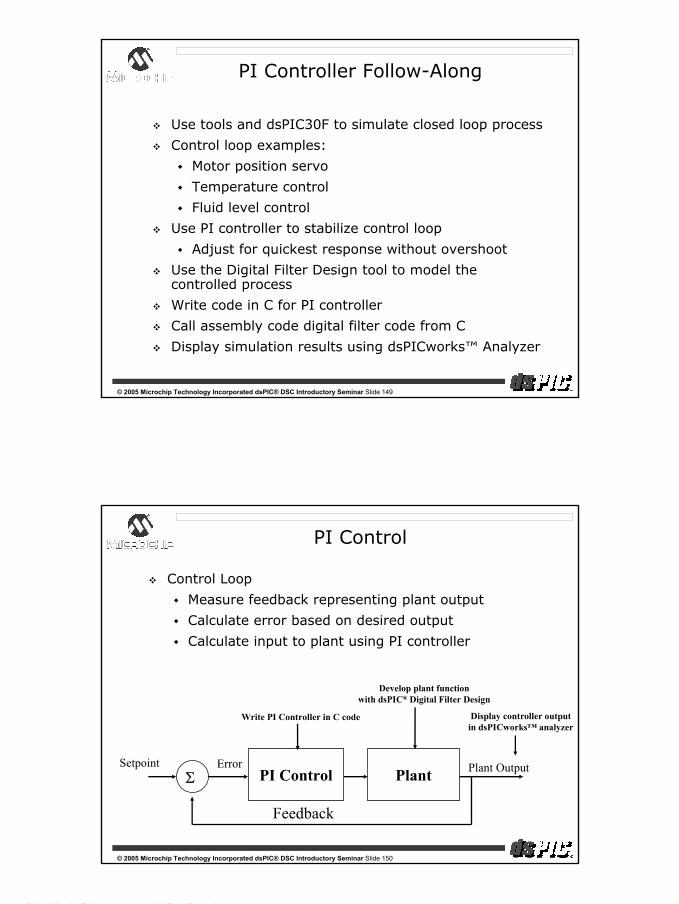
PI Control
PI Control PlantSetpoint
Feedback
ErrorΣ
Plant Output
Control Loop
Measure feedback representing plant output
Calculate error based on desired output
Calculate input to plant using PI controller
Write PI Controller in C code
Develop plant functionwith dsPIC® Digital Filter Design
Display controller outputin dsPICworks™ analyzer

dsPIC® DSC Introductory Seminar
© 2004, Microchip Technology Incorporated, All Rights Reserved.
76
© 2005 Microchip Technology Incorporated dsPIC® DSC Introductory Seminar Slide 151
PI Control
What does a PI(D) controller do?
(P)roportional term responds to magnitude of error
(I)ntegral term responds to time accumulation of error
(D)erivative term responds to time change in error
Proportional term sets overall response of controller
Integral term corrects small steady-state errors
Derivative term speeds up/slows down response
PID controller allows empirical tuning of system
‘Tweak’ knobs until system is well-behaved
PID_Output = err*Kp + Σerr*Ki + ∆err*Kd
© 2005 Microchip Technology Incorporated dsPIC® DSC Introductory Seminar Slide 152
Hands-on Session—Part 2
See Appendix F
PI Controller Hands-on

dsPIC® DSC Introductory Seminar
© 2004, Microchip Technology Incorporated, All Rights Reserved.
77
© 2005 Microchip Technology Incorporated dsPIC® DSC Introductory Seminar Slide 153
Seminar Agenda
Session Time
Corporate Overview 9:00—9:15am
Architecture 9:15—10:30am
Break 10:30—10:45am
MPLAB® VDI Demonstration 10:45—11:15am
Peripherals 11:15—11:50am
Live Demonstrations 11:50—12:30pm
Lunch 12:30—1:30pm
Software/Hardware Tools 1:30—1:50pm
Hands-on 1:50—2:50pm
Libraries/Applications 2:50—3:15pm
Session Wrap-up 3:15—3:30pm
© 2005 Microchip Technology Incorporated dsPIC® DSC Introductory Seminar Slide 154
dsPIC30F Libraries and Tools
Trusted software to speed up
your development cycle
dsPIC® DSC Introductory Seminar
© 2004, Microchip Technology Incorporated, All Rights Reserved.
78
© 2005 Microchip Technology Incorporated dsPIC® DSC Introductory Seminar Slide 155
dsPIC30F Libraries
Developed by Microchip and reputable third parties
Ease of use for getting your application running
Optimized for dsPIC30F architecture
Smallest footprint (RAM and Flash)
Fast execution
Compliant with Microchip MPLAB® C30 C Compiler development tools
Three Classes of Tools and Libraries
General Libraries—DSP, Math and Peripheral
Application Libraries—Encryption, Noise Suppression, more.
Desk Top Tools—dsPIC® Digital Filter Design, dsPICworks™ Visual Algorithm Analyzer
© 2005 Microchip Technology Incorporated dsPIC® DSC Introductory Seminar Slide 156
General Libraries
These libraries are generic enough
to be used by most applications

dsPIC® DSC Introductory Seminar
© 2004, Microchip Technology Incorporated, All Rights Reserved.
79
© 2005 Microchip Technology Incorporated dsPIC® DSC Introductory Seminar Slide 157
Math Library
Supports all of <MATH.H> from ANSI “C”
Trigonometric Functions
Exponent and Log Functions
Power, Square Root, Floor, Ceiling, etc.
IEEE-754 Compliant
Optimized for code size, developed in Assembly
Supports 2 data types
32-bit floating point
64-bit double
Benefits any application which uses floats/doubles
C and assembly callable
FREE
© 2005 Microchip Technology Incorporated dsPIC® DSC Introductory Seminar Slide 158
DSP Library
Libraries for your DSP requirements
Collection of 49 of the most common DSP functions
Vector and Matrix Functions
Add, Subtract, Multiply, Max, Min
Convolution, Correlation, Power, etc...
Filter Functions—block and single sample processing
FIR, IIR, Adaptive LMS, Lattice and more
Transform Functions
FFT, Inverse FFT, Discrete Cosine Transform
Window Functions
Bartlett, Blackman, Hamming, Hanning, Kaiser
Most functions are hand coded in assembly language
Fast execution time, C and assembly callable
FREE

dsPIC® DSC Introductory Seminar
© 2004, Microchip Technology Incorporated, All Rights Reserved.
80
© 2005 Microchip Technology Incorporated dsPIC® DSC Introductory Seminar Slide 159
Peripheral Library
Libraries for initializing the dsPIC® DSC Peripherals
275 driver functions for all dsPIC30F modulesADC (10-bit and 12-bit)CAN, DCI I2C™, SPI™, UARTInput capture, output compareMotor control PWM, QEIExternal interrupts, I/O Ports, reset moduleTimers
Peripheral Library is written in CCompiled for size optimization
BenefitsMaster the peripheral learning curveEasy-to-learn standard interface
FREE
© 2005 Microchip Technology Incorporated dsPIC® DSC Introductory Seminar Slide 160
Real-Time Operating Systems (RTOS)
What is an RTOS?
What are the benefits of an RTOS?
Easy real-time management—well suited for...
Large applications
Scalable applications
Inter-task communication and event handling
Event flags, queues and message mailboxes
Code becomes well structured
Independent processes or “tasks”
Faster than the usual while(1) loop
Provides true preemption capability

dsPIC® DSC Introductory Seminar
© 2004, Microchip Technology Incorporated, All Rights Reserved.
81
© 2005 Microchip Technology Incorporated dsPIC® DSC Introductory Seminar Slide 161
RTOS and the dsPIC30F
RTOS was written by CMX Systems, Inc.
Industry leading RTOS developer
3 different flavors were ported to the dsPIC® DSC
CMX-RTX™—full featured RTOS
CMX-Tiny+™—contains many features of CMX-RTX
CMX Scheduler™—limited to 5 tasks, minimal features
Each RTOS features
Small memory footprint
Fast context switch times
Reasonable interrupt latency
No royalty payments
FREE
© 2005 Microchip Technology Incorporated dsPIC® DSC Introductory Seminar Slide 162
Application Specific Libraries
These libraries provide a “system solution” which can be used as a major building block
for your design

dsPIC® DSC Introductory Seminar
© 2004, Microchip Technology Incorporated, All Rights Reserved.
82
© 2005 Microchip Technology Incorporated dsPIC® DSC Introductory Seminar Slide 163
Embedded Modem Library
Software Modem (soft-modem) Support
Replacing external modem chip with software!
Benefits
Single-chip integrated solution (up to 14.4 kbps)
Quick dialup and connection times
Perfect for small transactions on analog phone line
Application Examples
Home automation, remote access, security systems
POS applications, web-enabled devices
Tele-metering, remote upgrades
Library supplied with full DTMF Generation/Detection modules
© 2005 Microchip Technology Incorporated dsPIC® DSC Introductory Seminar Slide 164
Soft-Modem Resource Summary
ITU-T Specification
Bit Rate(bps)
RAM(Bytes)
Program Memory(Kbytes)
MIPS
V.32bis 14400 3600 36 15V.32 9600 3200 31 12V.22bis 2400 1700 22 7V.23 600/1200 1000 15 4.5V.21 300 1000 13 4.5V.42 (Error Corr.) na 2000 14 1.5
dsPIC30F implementation leaves room for other tasks...
FREE
Includes DTMF Library

dsPIC® DSC Introductory Seminar
© 2004, Microchip Technology Incorporated, All Rights Reserved.
83
© 2005 Microchip Technology Incorporated dsPIC® DSC Introductory Seminar Slide 165
Microchip FREE TCP/IP Stack for dsPIC
Main Features
Portable across dsPIC30F microcontrollers
Out of the box support for Microchip MPLAB C30 compiler
RTOS Independent
Full TCP State machine
Modular Design
Socket support for TCP and UDP
Microchip File System (MPFS)
Use it as a HTTP Server (included) or any customer TCP/IP based application
© 2005 Microchip Technology Incorporated dsPIC® DSC Introductory Seminar Slide 166
CMX-MicroNet Library
Features
A complete connectivity solution which supports...
HTTP Server
File transfers
E-mail client
Benefits
Single-chip solution
Small Flash and RAM requirements
One time fee—no royalties on deployed products
Target Products
Web browsers, remote monitoring, file transfer

dsPIC® DSC Introductory Seminar
© 2004, Microchip Technology Incorporated, All Rights Reserved.
84
© 2005 Microchip Technology Incorporated dsPIC® DSC Introductory Seminar Slide 167
CMX-MicroNet Protocols
Base Protocols
TCP (robust)
UDP (no handshaking)
IP (must have)
SLIP (serial port)
PPP (modem layer to ISP)
ARP (Ethernet address)
Application Layer Protocols
BOOTP
HTTP (Web Server)
FTP Server (File Transfer)
TFTP Client (UDP)
SMTP Client (E-Mail)
DHCP Client
Supported Physical Connections
Direct connect
Ethernet
Dialup (modem)
© 2005 Microchip Technology Incorporated dsPIC® DSC Introductory Seminar Slide 168
Performs speech compression / decompression
Encoder - 16:1 compression ratio
Speech input: 8 KHz, 16-bit mono
Encoded output: 8kbps data stream
Decoder
Decoder input: 8 kbps data stream
Speech output: 8 KHz, 16-bit mono
Based on Speex
Open source technology
Numerous PC plug-ins / apps readily available
www.speex.org
Includes PC Utility for making “playback” files
Speech Coding Library
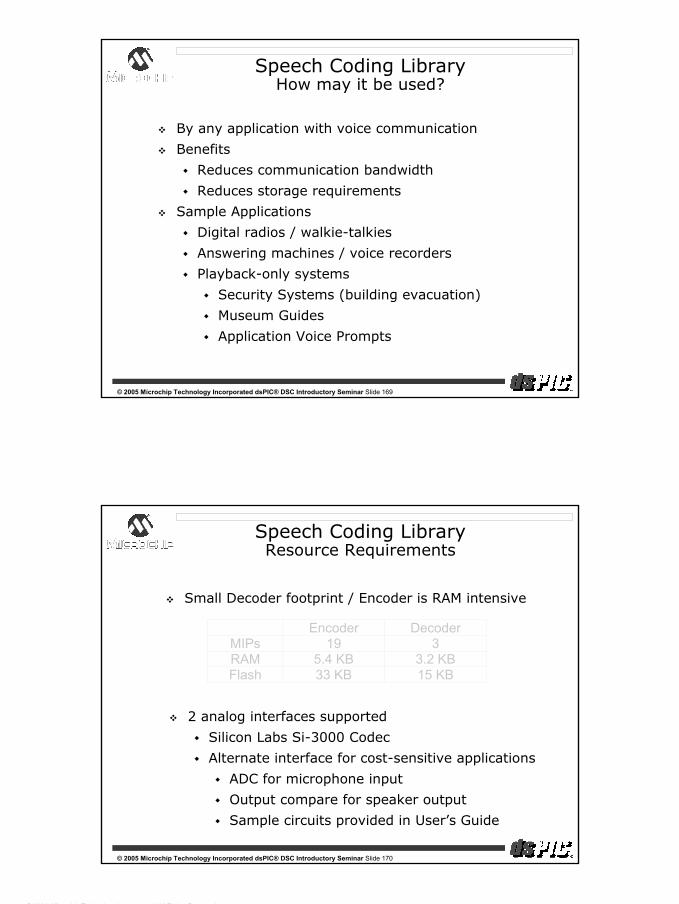
dsPIC® DSC Introductory Seminar
© 2004, Microchip Technology Incorporated, All Rights Reserved.
85
© 2005 Microchip Technology Incorporated dsPIC® DSC Introductory Seminar Slide 169
Speech Coding LibraryHow may it be used?
By any application with voice communication
Benefits
Reduces communication bandwidth
Reduces storage requirements
Sample Applications
Digital radios / walkie-talkies
Answering machines / voice recorders
Playback-only systems
Security Systems (building evacuation)
Museum Guides
Application Voice Prompts
© 2005 Microchip Technology Incorporated dsPIC® DSC Introductory Seminar Slide 170
Encoder DecoderMIPs 19 3RAM 5.4 KB 3.2 KBFlash 33 KB 15 KB
Small Decoder footprint / Encoder is RAM intensive
2 analog interfaces supported
Silicon Labs Si-3000 Codec
Alternate interface for cost-sensitive applications
ADC for microphone input
Output compare for speaker output
Sample circuits provided in User’s Guide
Speech Coding LibraryResource Requirements

dsPIC® DSC Introductory Seminar
© 2004, Microchip Technology Incorporated, All Rights Reserved.
86
© 2005 Microchip Technology Incorporated dsPIC® DSC Introductory Seminar Slide 171
Acoustic Echo Cancellation Library
Provides ‘far-end’ echo cancellation
Speaker output is picked up by the local microphone and transmitted back to the sender
Features
G.167-compliant algorithm (up to 64 msec)
Supports full-duplex operation
Receiver
G.167
Sender
G.167
AcousticEcho
TransmissionMedium
Speech
© 2005 Microchip Technology Incorporated dsPIC® DSC Introductory Seminar Slide 172
Acoustic Echo Cancellation Library
G.167 CPU Resources
Target Applications
Speakerphone
Hands-free car phone
Intercom
Emergency alarm units
Echo DelayRAM(KB)
Program Memory
(KB)MIPS
16 msec 4.6* 6 7.532 msec 5.4* 6 10.564 msec 7.7* 6 16.5
* Includes up to 2KB for CODEC and UART buffers and A/U-law compression

dsPIC® DSC Introductory Seminar
© 2004, Microchip Technology Incorporated, All Rights Reserved.
87
© 2005 Microchip Technology Incorporated dsPIC® DSC Introductory Seminar Slide 173
Noise Suppression Library
Removes extraneous noise picked up by microphone
Voice activity detector differentiates noise and speech
Noise reduction filters adjust every 10 ms during periods of speech inactivity (uses FFT analysis)
Speech is continuously filtered, reducing noise
Noise Suppression
Library
Comm. System
Speech
Noise
Noise
Speech—Noise
© 2005 Microchip Technology Incorporated dsPIC® DSC Introductory Seminar Slide 174
Noise Suppression Library
Noise Suppression CPU Resources
3.3 MIPS
5 Kbytes Flash memory
2 Kbytes RAM
Includes up to 1 Kbyte for buffering Codec data
Target Applications
Front end for any voice based system
Headsets
Hands-free telephone
Intercom
Speech recognition
Speech coding
dsPIC® DSC Introductory Seminar
© 2004, Microchip Technology Incorporated, All Rights Reserved.
88
© 2005 Microchip Technology Incorporated dsPIC® DSC Introductory Seminar Slide 175
Embedded Encryption Libraries
dsPIC30F Symmetric Key Library
Message Digests: SHA-1, MD5
Symmetric Key Encryption: T-DES, AES
Deterministic Random Bit Generator: ANSI X9.82
dsPIC30F Asymmetric Key Library
Signing and Verification: RSA, DSA
Public Key Encryption: RSA
Key Agreement Protocol: Diffie-Hellman
Big Integer Arithmetic Package
© 2005 Microchip Technology Incorporated dsPIC® DSC Introductory Seminar Slide 176
Embedded Encryption Applications
Secure Web Transactions
Secure web access (SSL/TLS)
E-mail (S/MIME), secure XML transactions, and Virtual Private Networks (IPsec)
Smart Card Readers
PDAs and other mobile devices
Secure communications between a dsPIC® DSC application and personal computers
Trusted Computing Group (TCG)
Microsoft® Next Generation Secure Computing Base (NGSCB)

dsPIC® DSC Introductory Seminar
© 2004, Microchip Technology Incorporated, All Rights Reserved.
89
© 2005 Microchip Technology Incorporated dsPIC® DSC Introductory Seminar Slide 177
Motor Control Solutions
© 2005 Microchip Technology Incorporated dsPIC® DSC Introductory Seminar Slide 178
dsPIC30F for Motor Control
When is dsPIC30F needed for motor control?
Closed loop variable speed control
Eliminate sensors
High speed operation
Support other tasks
dsPIC30F benefits
16-bit math
Fast 10-bit A/D converter - (1 Msps)
Dedicated motor peripherals (PWM and QEI)
Large program memory, large RAM

dsPIC® DSC Introductory Seminar
© 2004, Microchip Technology Incorporated, All Rights Reserved.
90
© 2005 Microchip Technology Incorporated dsPIC® DSC Introductory Seminar Slide 179
Motor Control Solutions
Vector Control of AC Induction Motor
Open Loop AC Induction Motor Control
Sensorless Control of Brushless DC Motor
Sensored Control of Brushless DC Motor
dsPICDEM™ MC1 Motor Control Development System
PICDEM™ MCLV Motor Control Development Board
dsPICDEM™ MC1 Motor Control Development System allows rapid development of motor control software.
© 2005 Microchip Technology Incorporated dsPIC® DSC Introductory Seminar Slide 180
Vector Control of ACIM
ACIM is widely used
Why? Simple construction and AC power
Can be difficult to control variable speed
Vector math makes AC motor look like DC motor
Less expensive ACIM is better controlled
Benefits of vector control
Current, torque and speed controlled closed-loop
Transient response to load changes
Efficiency

dsPIC® DSC Introductory Seminar
© 2004, Microchip Technology Incorporated, All Rights Reserved.
91
© 2005 Microchip Technology Incorporated dsPIC® DSC Introductory Seminar Slide 181
Vector Control of ACIM
Closed-loop control for 3-phase motors
Microchip Application Note: AN-908
Well-documented solution including source code
Designed to run on motor control board
Example Applications
Residential
Washing machine, electric scooter
Industrial
Conveyor, hoist, mixer
Automotive
Electrically driven engine accessories
FREE
© 2005 Microchip Technology Incorporated dsPIC® DSC Introductory Seminar Slide 182
Open Loop Control of ACIM
Open-loop control for 1-phase 3-phase motors
Microchip Application Note: AN-984
Well-documented solution including source code
Designed to run on dsPICDEM™ MC1 System
Introductory application note to help you get started with AC Induction Motor control
FREE

dsPIC® DSC Introductory Seminar
© 2004, Microchip Technology Incorporated, All Rights Reserved.
92
© 2005 Microchip Technology Incorporated dsPIC® DSC Introductory Seminar Slide 183
Sensorless BLDC Control
BLDC is an ‘inside-out’ brush DC motor
External sensors replace the function of brushes and tell external logic when to energize phases (similar to automotive engine distributor)
Sensorless approach monitors motor phases during non-driven periods to find timing reference points using A/D converter
dsPIC® DSC performs sensorless commutation, current control, speed control, and sensorless error detection
© 2005 Microchip Technology Incorporated dsPIC® DSC Introductory Seminar Slide 184
Sensorless BLDC Control
Microchip Application Note: AN-901
Who can use sensorless BLDC control?
Application needs efficiency of BLDC motor
Low speed operation not required
Closed loop control needed, but not fast response
Want to eliminate cost of sensors, wiring
Sensors cannot tolerate operating environment
Sensorless algorithm well suited for fans, pumps
HVAC blower motor
Refrigerator compressor
Automotive fuel pump, radiator fan
Medical tool/instruments
FREE

dsPIC® DSC Introductory Seminar
© 2004, Microchip Technology Incorporated, All Rights Reserved.
93
© 2005 Microchip Technology Incorporated dsPIC® DSC Introductory Seminar Slide 185
Sensorless BLDC Control
Microchip Application Note: (June 2005 release)
Sensorless BLDC motor Control using 28-pin dsPIC30F devices
AN901 code transferred to dsPIC30F2010
Operates on PICDEM™ MCLV board
Code has optional ASCII Serial User Interface to set all Control, Motor and User Parameters
FREE
© 2005 Microchip Technology Incorporated dsPIC® DSC Introductory Seminar Slide 186
Available Q3
Sensorless BLDC Control
Sensorless BLDC Motor Control GUI
Included for free with MPLAB® software
Tune control loops and starting parameters with MPLAB ICD 2
Shorten sensorless software development time

dsPIC® DSC Introductory Seminar
© 2004, Microchip Technology Incorporated, All Rights Reserved.
94
© 2005 Microchip Technology Incorporated dsPIC® DSC Introductory Seminar Slide 187
PICDEM™ MCLV Board
Supports dsPIC30F2010 and PIC18F23X1
Supports BLDC from 10V to 40V DC
Hall sensor or sensorless control
Out-of-Box: 24V Pwr. Supply, Hurst BLDC motor dsPIC30F2010 and PIC18F23X1 firmware
MPLAB® ICD 2 Debug/Programming capability
Serial Interface
New
© 2005 Microchip Technology Incorporated dsPIC® DSC Introductory Seminar Slide 188
Motor Control Solutions
AlgorithmRAM
(Bytes)
Program Memory
(KB)MIPS
Vector ACIM 244 7.3 9
Sensorless BLDC 268 10 5
CPU Resource Requirements for Advanced Algorithms
Small code footprints!
ACIM and BLDC will run on the dsPIC30F2010

dsPIC® DSC Introductory Seminar
© 2004, Microchip Technology Incorporated, All Rights Reserved.
95
© 2005 Microchip Technology Incorporated dsPIC® DSC Introductory Seminar Slide 189
Seminar Agenda
Session Time
Corporate Overview 9:00—9:15am
Architecture 9:15—10:30am
Break 10:30—10:45am
MPLAB® VDI Demonstration 10:45—11:15am
Peripherals 11:15—11:50am
Live Demonstrations 11:50—12:30pm
Lunch 12:30—1:30pm
Software/Hardware Tools 1:30—1:50pm
Hands-on 1:50—2:50pm
Libraries/Applications 2:50—3:15pm
Session Wrap-up 3:15—3:30pm
© 2005 Microchip Technology Incorporated dsPIC® DSC Introductory Seminar Slide 190
Where do you go from here?
Microchip web site
Web Seminars
Workshop-in-a-Box
Key dsPIC® DSC documents to review
Microchip online discussion groups
Application development platforms
buy.microchip.com
MASTERs 2005

dsPIC® DSC Introductory Seminar
© 2004, Microchip Technology Incorporated, All Rights Reserved.
96
© 2005 Microchip Technology Incorporated dsPIC® DSC Introductory Seminar Slide 191
dsPIC30F Product Families
Motor Control & Power Conversion Family
Brushless DC motor controlAC induction motor controlSwitch reluctance motor controlUPS, inverters and power supplies
AppliancesPower toolsAutomotiveIndustrial
Product Pins
FlashKB
SRAMBytes
EEBytes
Timer16-bit
InputCap
OutputComp/
StdPWM
Motor Cntrl PWM
10-bit A/D
500 Ksps(2 us)
Quad Enc
UART
SPI™
I2
C™
CAN
dsPIC30F2010 28 12 512 1024 3 4 2 6 6 ch Yes 1 1 1
dsPIC30F3010 28 24 1024 1024 5 4 2 6 6 ch Yes 1 1 1
dsPIC30F4012 28 48 2048 1024 5 4 2 6 6 ch Yes 1 1 1 1
dsPIC30F3011 40 24 1024 1024 5 4 4 6 9 ch Yes 2 1 1
dsPIC30F4011 40 48 2048 1024 5 4 4 6 9 ch Yes 2 1 1 1
dsPIC30F5015 64 66 2048 1024 5 4 4 8 16 ch Yes 1 2 1 1
dsPIC30F6010 80 144 8192 4096 5 8 8 8 16 ch Yes 2 2 1 2
All dsPIC® DSC Released to Production (except 5015)
© 2005 Microchip Technology Incorporated dsPIC® DSC Introductory Seminar Slide 192
General Purpose Family
Product Pins FlashKB
SRAMBytes
EEBytes
Timer16-bit
InputCapture
OutputCompareStd PWM
A/D12-bit100
KSPS
UART
SPI™
I2
C™
CAN
Codec Interface
dsPIC30F3014 40 24 2048 1024 3 2 2 13 ch 2 1 1
dsPIC30F4013 40 48 2048 1024 5 4 4 13 ch 2 1 1 1 AC97, I2S
dsPIC30F5011 64 66 4096 1024 5 8 8 16 ch 2 2 1 2 AC97, I2S
dsPIC30F6011 64 132 6144 2048 5 8 8 16 ch 2 2 1 2
dsPIC30F6012 64 144 8192 4096 5 8 8 16 ch 2 2 1 2 AC97, I2S
dsPIC30F5013 80 66 4096 1024 5 8 8 16 ch 2 2 1 2 AC97, I2S
dsPIC30F6013 80 132 6144 2048 5 8 8 16 ch 2 2 1 2
dsPIC30F6014 80 144 8192 4096 5 8 8 16 ch 2 2 1 2 AC97, I2S
dsPIC30F Product Families
Classic General Purpose 16-bit Controller FamilyMembers with codec are ideal for speech/audio applications
All dsPIC® DSC listed are Released to Production

dsPIC® DSC Introductory Seminar
© 2004, Microchip Technology Incorporated, All Rights Reserved.
97
© 2005 Microchip Technology Incorporated dsPIC® DSC Introductory Seminar Slide 193
dsPIC30F Product Families
ProductPins Flash
KBSRAMBytes
EEBytes
Timer16-bit
InputCapture
OutputCompareStd PWM
12-bit A/D100 Ksps(10us)
UART
SPI™
I2
C™
CAN
dsPIC30F2011 18 12 1024 3 2 2 8 ch 1 1 1
dsPIC30F3012 18 24 2048 1024 3 2 2 8 ch 1 1 1
dsPIC30F2012 28 12 1024 3 2 2 8 ch 1 1 1
dsPIC30F3013 28 24 2048 1024 3 2 2 8 ch 2 1 1
Sensor Processor Family
Glass break detectGas sensorTorque sensorSteering angle sensorVoice activationBar code reader
Low power, smart sensorAirbag smart sensorPressure sensorsVibration measurementGyroscope
All dsPIC® DSC listed are Released to Production
© 2005 Microchip Technology Incorporated dsPIC® DSC Introductory Seminar Slide 194
Microchip Application Support
www.microchip.comData Sheets, Application Notes, Design Centers
Order Free SamplesSelect Best Devices

dsPIC® DSC Introductory Seminar
© 2004, Microchip Technology Incorporated, All Rights Reserved.
98
© 2005 Microchip Technology Incorporated dsPIC® DSC Introductory Seminar Slide 195
What is a dsPIC® DSC?
Introduction to the dsPIC30F Architecture (2 modules)
dsPIC30F Addressing Modes (2 modules)
dsPIC30F DSP Engine & ALU
dsPIC30F Interrupts
dsPIC30F 12-bit ADC Module (2 modules)
dsPIC30F 10-bit ADC Module (2 modules)
dsPIC30F Motor Control PWM Module
dsPIC30F Quadrature Encoder Interface Module
dsPIC30F UART Communication Module
dsPIC30F SPI™ Communication Module
dsPIC30F CAN Communication Module
dsPIC30F I2C™ Communication Module
dsPIC30F General Purpose Timer Module
dsPIC30F On-Line Web Seminars
© 2005 Microchip Technology Incorporated dsPIC® DSC Introductory Seminar Slide 196
Workshop in a Box TrainingGetting Started
dsPIC® DSC Workshop in a Box (WIB)6 hour training session with hands-on exercises
Focused on Getting Started with the basics
Use laptops and MPLAB® ICD 2 (supplied)
Purchase a kit for US $99.00 retail
Includes dsPICDEM™ 1.1 Development Board
Microchip and Distributor FAEs conduct the training

dsPIC® DSC Introductory Seminar
© 2004, Microchip Technology Incorporated, All Rights Reserved.
99
© 2005 Microchip Technology Incorporated dsPIC® DSC Introductory Seminar Slide 197
dsPIC® DSC Workshop in a Box (WIB)6 hour training session with hands-on exercises
Focused on BLDC motor, Sensored and Sensorless control
Use laptops, MPLAB® ICD 2 and BLDC motor (supplied)
Purchase a kit for US $99.00 retail (w/o motor)
Includes PICDEM™ MCLV Development Board
Microchip and Distributor FAEs conduct the training
Release: CQ3 2005
Coming Soon !
Workshop in a Box TrainingBLDC Motor Control
© 2005 Microchip Technology Incorporated dsPIC® DSC Introductory Seminar Slide 198
Device Selection Reference Document#
General Purpose and Sensor Family Data Sheet DS70083
Motor Control and Power Conv. Data Sheet DS70082
Product Family Overview DS70043
Base Design Reference Document#
dsPIC30F Family Reference Manual DS70046
dsPIC30F Programmer’s Reference Manual DS70030
MPLAB® C30 C Compiler’s User’s Guide DS51284
MPLAB ASM30, LINK30 & Utilities User’s Guide DS51317
dsPIC® DSC Key Support Documents
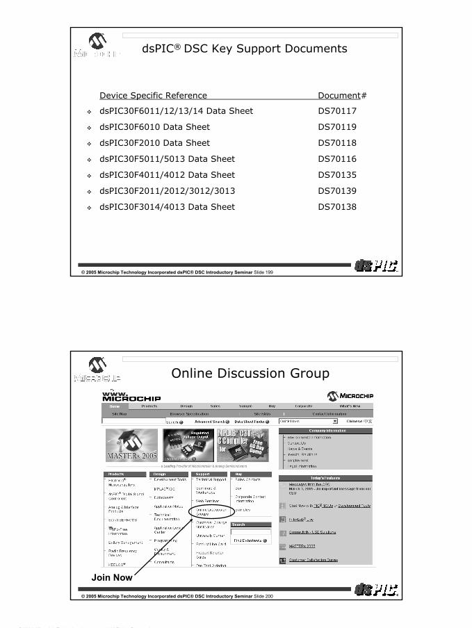
dsPIC® DSC Introductory Seminar
© 2004, Microchip Technology Incorporated, All Rights Reserved.
100
© 2005 Microchip Technology Incorporated dsPIC® DSC Introductory Seminar Slide 199
Device Specific Reference Document#
dsPIC30F6011/12/13/14 Data Sheet DS70117
dsPIC30F6010 Data Sheet DS70119
dsPIC30F2010 Data Sheet DS70118
dsPIC30F5011/5013 Data Sheet DS70116
dsPIC30F4011/4012 Data Sheet DS70135
dsPIC30F2011/2012/3012/3013 DS70139
dsPIC30F3014/4013 Data Sheet DS70138
dsPIC® DSC Key Support Documents
© 2005 Microchip Technology Incorporated dsPIC® DSC Introductory Seminar Slide 200
Online Discussion Group
Join Now

dsPIC® DSC Introductory Seminar
© 2004, Microchip Technology Incorporated, All Rights Reserved.
101
© 2005 Microchip Technology Incorporated dsPIC® DSC Introductory Seminar Slide 201
MASTERs Conference
© 2005 Microchip Technology Incorporated dsPIC® DSC Introductory Seminar Slide 202
dsPIC30F
Looks Like a MCU
Performs Like a DSP
Priced Like a MCU
The 16-bit MCU with the power of DSP

dsPIC® DSC Introductory Seminar
© 2004, Microchip Technology Incorporated, All Rights Reserved.
102
© 2005 Microchip Technology Incorporated dsPIC® DSC Introductory Seminar Slide 203
That’s It!!
Thank You!
© 2005 Microchip Technology Incorporated dsPIC® DSC Introductory Seminar Slide 204
Appendices

dsPIC® DSC Introductory Seminar
© 2004, Microchip Technology Incorporated, All Rights Reserved.
103
© 2005 Microchip Technology Incorporated dsPIC® DSC Introductory Seminar Slide 205
Demos/Hands-on
Demos
Appendix A—Getting started with MPLAB® VDI
Appendix B—MPLAB® IDE Demo
Appendix C—Debugging with MPLAB ICD 2
Hands-on
Appendix D—Using dsPIC® Filter Design Lite
Appendix E—Using dsPICworks™ Analyzer
Appendix F—PI Controller
© 2005 Microchip Technology Incorporated dsPIC® DSC Introductory Seminar Slide 206
Appendix A
Demo 1
Getting your dsPIC® DSC initialized with MPLAB® VDI

dsPIC® DSC Introductory Seminar
© 2004, Microchip Technology Incorporated, All Rights Reserved.
104
© 2005 Microchip Technology Incorporated dsPIC® DSC Introductory Seminar Slide 207
MPLAB® VDI—Demo 1
Open tools1.mcw
Click Tools > Visual Initializer to open MPLAB VDI
© 2005 Microchip Technology Incorporated dsPIC® DSC Introductory Seminar Slide 208
MPLAB® VDI—Demo
Click on the 16-bit Timer1 icon
Configure the Timer1 peripheral
Enable module
Enable interrupt
Prescaler = 1:256
Time period = 500 ms

dsPIC® DSC Introductory Seminar
© 2004, Microchip Technology Incorporated, All Rights Reserved.
105
© 2005 Microchip Technology Incorporated dsPIC® DSC Introductory Seminar Slide 209
MPLAB® VDI—Demo
Build, program and run
LED blinks every 1 sec!
© 2005 Microchip Technology Incorporated dsPIC® DSC Introductory Seminar Slide 210
Appendix B
Demo 2

dsPIC® DSC Introductory Seminar
© 2004, Microchip Technology Incorporated, All Rights Reserved.
106
© 2005 Microchip Technology Incorporated dsPIC® DSC Introductory Seminar Slide 211
MPLAB® IDE—Demo 2
Learn to use dsPIC30F tools in MPLAB IDE
Four steps
Step 1—Create a project in MPLAB IDE
Step 2—Compile code using the MPLAB C30 C Compiler
Step 3—Program a dsPIC30F device on a dsPICDEM™ 28-pin Starter Demo Board using MPLAB ICD 2
Step 4—Run and debug code on a dsPICDEM 28-pin Starter Demo Board using MPLAB ICD 2
© 2005 Microchip Technology Incorporated dsPIC® DSC Introductory Seminar Slide 212
Step 1
Creating an MPLAB® IDE Project

dsPIC® DSC Introductory Seminar
© 2004, Microchip Technology Incorporated, All Rights Reserved.
107
© 2005 Microchip Technology Incorporated dsPIC® DSC Introductory Seminar Slide 213
Creating an MPLAB® IDE Project
Start MPLAB IDE
Project View
Menu BarTool Bar
Output View
Status Bar
© 2005 Microchip Technology Incorporated dsPIC® DSC Introductory Seminar Slide 214
Creating an MPLAB® IDE Project
Click Project menu
Select Project Wizard
Project Wizard screen opens
Click Next
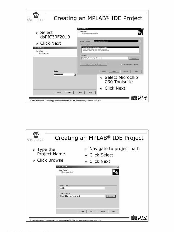
dsPIC® DSC Introductory Seminar
© 2004, Microchip Technology Incorporated, All Rights Reserved.
108
© 2005 Microchip Technology Incorporated dsPIC® DSC Introductory Seminar Slide 215
Creating an MPLAB® IDE Project
Select dsPIC30F2010
Click Next
Select Microchip C30 Toolsuite
Click Next
© 2005 Microchip Technology Incorporated dsPIC® DSC Introductory Seminar Slide 216
Creating an MPLAB® IDE Project
Type the Project Name
Click Browse
Navigate to project path
Click Select
Click Next

dsPIC® DSC Introductory Seminar
© 2004, Microchip Technology Incorporated, All Rights Reserved.
109
© 2005 Microchip Technology Incorporated dsPIC® DSC Introductory Seminar Slide 217
Creating an MPLAB® IDE Project
Select the required source files and linker script file (p30F2010.gld)
Click Add and Next
© 2005 Microchip Technology Incorporated dsPIC® DSC Introductory Seminar Slide 218
Creating an MPLAB® IDE Project
Summary screen appears
Click Finish
This creates a Workspace (.mcw) and a Project (.mcp) file
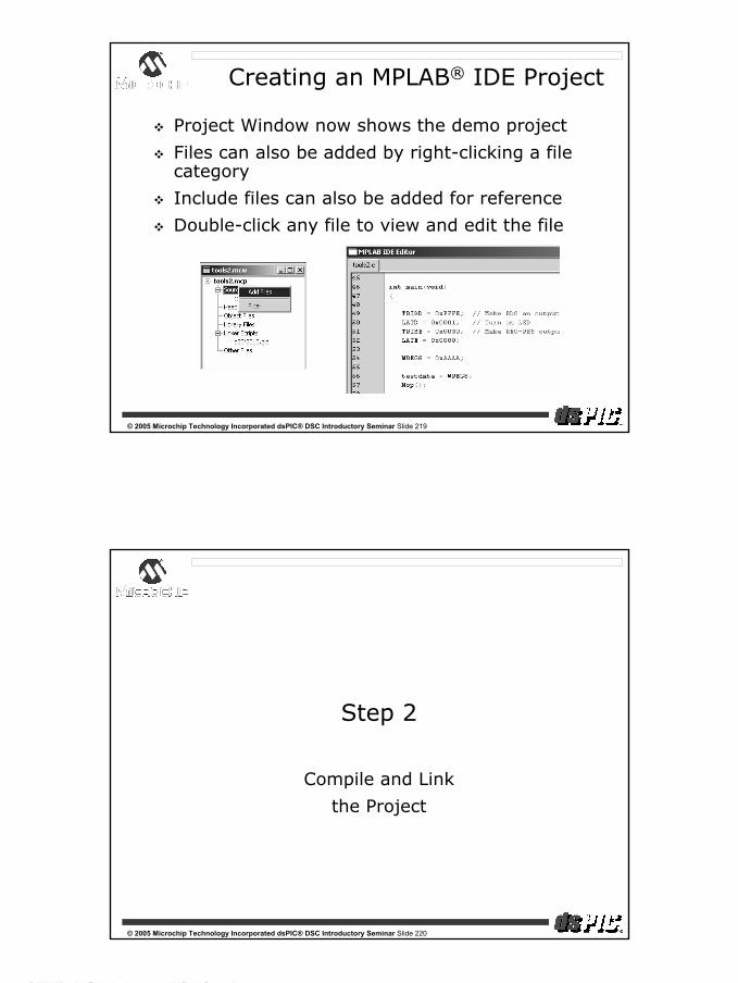
dsPIC® DSC Introductory Seminar
© 2004, Microchip Technology Incorporated, All Rights Reserved.
110
© 2005 Microchip Technology Incorporated dsPIC® DSC Introductory Seminar Slide 219
Creating an MPLAB® IDE Project
Project Window now shows the demo project
Files can also be added by right-clicking a file category
Include files can also be added for reference
Double-click any file to view and edit the file
© 2005 Microchip Technology Incorporated dsPIC® DSC Introductory Seminar Slide 220
Step 2
Compile and Link
the Project

dsPIC® DSC Introductory Seminar
© 2004, Microchip Technology Incorporated, All Rights Reserved.
111
© 2005 Microchip Technology Incorporated dsPIC® DSC Introductory Seminar Slide 221
Compiling and Linking an MPLAB® IDE Project
Before we compile and link:
Tell compiler where to find device header file
#include <p30F2010.h>
Tell linker to reserve RAM for MPLAB ICD 2
Click Project menu, and select Build Options > Project
© 2005 Microchip Technology Incorporated dsPIC® DSC Introductory Seminar Slide 222
Find Include Path
Click Browse
Compiling and Linking an MPLAB® IDE Project

dsPIC® DSC Introductory Seminar
© 2004, Microchip Technology Incorporated, All Rights Reserved.
112
© 2005 Microchip Technology Incorporated dsPIC® DSC Introductory Seminar Slide 223
Include path now points to header files
Click MPLAB LINK30 tabSelect Link for ICD 2 and click OK
Compiling and Linking an MPLAB® IDE Project
© 2005 Microchip Technology Incorporated dsPIC® DSC Introductory Seminar Slide 224
Click Project menu
Select Make
Compiling and Linking an MPLAB® IDE Project

dsPIC® DSC Introductory Seminar
© 2004, Microchip Technology Incorporated, All Rights Reserved.
113
© 2005 Microchip Technology Incorporated dsPIC® DSC Introductory Seminar Slide 225
Build results, and sizes of various code sections, are shown in Output window
Compiling and Linking an MPLAB® IDE Project
© 2005 Microchip Technology Incorporated dsPIC® DSC Introductory Seminar Slide 226
Step 3
Use the MPLAB® ICD 2
to program
the code

dsPIC® DSC Introductory Seminar
© 2004, Microchip Technology Incorporated, All Rights Reserved.
114
© 2005 Microchip Technology Incorporated dsPIC® DSC Introductory Seminar Slide 227
Programming the Device
Hardware
MPLAB® ICD 2
dsPICDEM™ 28-pin Starter Demo Board
© 2005 Microchip Technology Incorporated dsPIC® DSC Introductory Seminar Slide 228
Programming the device
Set up the hardware
Connect power to the dsPICDEM™ 28-pin Demo Board
Connect USB cable from PC to MPLAB®
ICD 2
Connect MPLAB ICD 2 to the board
Click Debugger menu
Choose Select Tool and MPLAB ICD 2

dsPIC® DSC Introductory Seminar
© 2004, Microchip Technology Incorporated, All Rights Reserved.
115
© 2005 Microchip Technology Incorporated dsPIC® DSC Introductory Seminar Slide 229
Programming the device
Click Debugger menu
Choose Connect
Operating System Download
MPLAB® IDE may ask to download a new operating system
Click Yes
© 2005 Microchip Technology Incorporated dsPIC® DSC Introductory Seminar Slide 230
Programming the Device
Output window
MPLAB® ICD 2 automatically identifies the target device
Click Debugger menu and Program

dsPIC® DSC Introductory Seminar
© 2004, Microchip Technology Incorporated, All Rights Reserved.
116
© 2005 Microchip Technology Incorporated dsPIC® DSC Introductory Seminar Slide 231
Step 4
Use the MPLAB® ICD 2
debugging features
© 2005 Microchip Technology Incorporated dsPIC® DSC Introductory Seminar Slide 232
Running and Debugging
Click View menu
Choose Program Memory
Press F6 to Reset
Press F9 to Run
Press F5 to Halt

dsPIC® DSC Introductory Seminar
© 2004, Microchip Technology Incorporated, All Rights Reserved.
117
© 2005 Microchip Technology Incorporated dsPIC® DSC Introductory Seminar Slide 233
Running and Debugging
3 different debugging options
Program Memory window (shown in previous slide)
C or assembly source file
Simply open source file
Disassembly window
Click View menu and Disassembly Listing
Observe the compact code!
© 2005 Microchip Technology Incorporated dsPIC® DSC Introductory Seminar Slide 234
Running and Debugging
Reset, Right-click the line to run to, and choose Run to Cursor
Instructions up to the next line are executed, and the arrow points to the next line

dsPIC® DSC Introductory Seminar
© 2004, Microchip Technology Incorporated, All Rights Reserved.
118
© 2005 Microchip Technology Incorporated dsPIC® DSC Introductory Seminar Slide 235
Running and Debugging
Find the line on which you want to break
Right-click and choose Set Breakpoint
Press F6 and then F9 to Run
Green arrow points to line with breakpoint
© 2005 Microchip Technology Incorporated dsPIC® DSC Introductory Seminar Slide 236
Running and Debugging
Press F7 to single step a line of code
Press F8 to step over a function call
After each single step, green arrow points to the next instruction to be executed

dsPIC® DSC Introductory Seminar
© 2004, Microchip Technology Incorporated, All Rights Reserved.
119
© 2005 Microchip Technology Incorporated dsPIC® DSC Introductory Seminar Slide 237
Running and Debugging
Click View menu
Choose Watch
Select the register to be watched
Click Add SFR
For user variables, use Add Symbol instead
© 2005 Microchip Technology Incorporated dsPIC® DSC Introductory Seminar Slide 238
Running and Debugging
Watch window gets updated on a Breakpoint, Halt or Reset
Watch window can also be refreshed by right-clicking and choosing Refresh
Double-clicking the Value field enables modifying the value of SFRs or variables added to Watch

dsPIC® DSC Introductory Seminar
© 2004, Microchip Technology Incorporated, All Rights Reserved.
120
© 2005 Microchip Technology Incorporated dsPIC® DSC Introductory Seminar Slide 239
Running and Debugging
Watch window values can be displayed in several data formats
Right-click the variable and select Properties
© 2005 Microchip Technology Incorporated dsPIC® DSC Introductory Seminar Slide 240
Advanced Breakpoints
Breakpoint on X bus write
Specify the X bus write address which should trigger a breakpoint
Reset and run the codeWrite Breakpoint

dsPIC® DSC Introductory Seminar
© 2004, Microchip Technology Incorporated, All Rights Reserved.
121
© 2005 Microchip Technology Incorporated dsPIC® DSC Introductory Seminar Slide 241
Advanced Breakpoints
Breakpoint on X bus read
Specify the X bus read address which should trigger a breakpoint
Reset and run the code Read Breakpoint
© 2005 Microchip Technology Incorporated dsPIC® DSC Introductory Seminar Slide 242
Advanced Breakpoints
Breakpoint on X bus write of specific word (or byte)
Specify the required write address and data value which should trigger a breakpoint
Write Breakpoint

dsPIC® DSC Introductory Seminar
© 2004, Microchip Technology Incorporated, All Rights Reserved.
122
© 2005 Microchip Technology Incorporated dsPIC® DSC Introductory Seminar Slide 243
Advanced Breakpoints
Breakpoint on X bus read of specific word (or byte)
Specify the required read address and data value which should trigger a breakpoint
Read Breakpoint
© 2005 Microchip Technology Incorporated dsPIC® DSC Introductory Seminar Slide 244
Advanced Breakpoints
Now change Data Value
Now the code does not break in either case!!
Similar functionality for X bus byte reads/writes as well as Y bus word reads

dsPIC® DSC Introductory Seminar
© 2004, Microchip Technology Incorporated, All Rights Reserved.
123
© 2005 Microchip Technology Incorporated dsPIC® DSC Introductory Seminar Slide 245
Advanced Breakpoints
Breakpoint Pass Count—2 types
Break 5 instructions after breakpoint
Break 5 instructions after breakpoint
© 2005 Microchip Technology Incorporated dsPIC® DSC Introductory Seminar Slide 246
Advanced Breakpoints
Reset and run the code for each Pass Count Type
Code execution halts in either case
Break on 100 breakpoint hits
Break on 100 breakpoint hits

dsPIC® DSC Introductory Seminar
© 2004, Microchip Technology Incorporated, All Rights Reserved.
124
© 2005 Microchip Technology Incorporated dsPIC® DSC Introductory Seminar Slide 247
Appendix C
Demo 3
Debugging with MPLAB® ICD 2
© 2005 Microchip Technology Incorporated dsPIC® DSC Introductory Seminar Slide 248
MPLAB® IDE—Demo 3Learn to troubleshoot an application with MPLAB ICD 2
Objective: To blink the LED every 1 sec
Timer1 used to generate a 5 ms period
A variable “TimerTicks” counts the number of period matches
When TimerTicks = 100 (0.5 sec), LED is toggled
Build, program and run
LEDs are blinking too fast!!
Use Advanced Breakpoints to find the bug
Hint : Is TimerTicks prematurely getting set to 100 somehow? But where??

dsPIC® DSC Introductory Seminar
© 2004, Microchip Technology Incorporated, All Rights Reserved.
125
© 2005 Microchip Technology Incorporated dsPIC® DSC Introductory Seminar Slide 249
MPLAB® IDE—Demo 3
Set up an Advanced Breakpoint to test if TimerTicks is getting set to 100 in the code
Reset and run the program
© 2005 Microchip Technology Incorporated dsPIC® DSC Introductory Seminar Slide 250
MPLAB® IDE—Demo 3
Code halted immediately after
if (TimerTicks = 100)
Ah, there it is!!
Should be if (TimerTicks == 100), not if (TimerTicks = 100)

dsPIC® DSC Introductory Seminar
© 2004, Microchip Technology Incorporated, All Rights Reserved.
126
© 2005 Microchip Technology Incorporated dsPIC® DSC Introductory Seminar Slide 251
Appendix D
Hands-on
Using dsPIC® Filter Design Lite
© 2005 Microchip Technology Incorporated dsPIC® DSC Introductory Seminar Slide 252
Loading a Filter Spec File
Select “bsiir.spc” file in the browse window from under <Your Path:\>dsPIC Seminar\Follow_Along\Part 1\
Click here to loadfilter specification file

dsPIC® DSC Introductory Seminar
© 2004, Microchip Technology Incorporated, All Rights Reserved.
127
© 2005 Microchip Technology Incorporated dsPIC® DSC Introductory Seminar Slide 253
Choosing the Filter Type
For this demo the band-stop IIR filter has been selected
The *.spc file contains information on the nature of filtering action (high-pass, low-pass, band-pass or band-stop) and the filter’s exact specification
Click “Next”
© 2005 Microchip Technology Incorporated dsPIC® DSC Introductory Seminar Slide 254
Specifying the Filter Parameters
The filter specification will appear on this dialog box
This information is also retrieved from the *.SPC file
Click “Next”
User may enter desired filter
characteristics here

dsPIC® DSC Introductory Seminar
© 2004, Microchip Technology Incorporated, All Rights Reserved.
128
© 2005 Microchip Technology Incorporated dsPIC® DSC Introductory Seminar Slide 255
Filter Estimate
dsPIC® Filter Design estimates the filter order for several popular filter structures
The filter option with the best response for the given specification is pre-selected for the user by the tool!
Click “Next”
Best filter option advised by the tool
© 2005 Microchip Technology Incorporated dsPIC® DSC Introductory Seminar Slide 256
And you really wanted to calculate H(z) by hand!!!
PhaseResponse
Group Delay
Poles and Zeros
around theUnit Circle
MagnitudeResponse
ImpulseResponse
Step Response

dsPIC® DSC Introductory Seminar
© 2004, Microchip Technology Incorporated, All Rights Reserved.
129
© 2005 Microchip Technology Incorporated dsPIC® DSC Introductory Seminar Slide 257
Saving Off the Filter Coefficients
We now need to save the coefficients for the generated filter to a file
The filter coefficient file will be used in dsPICworks™ Analyzer to simulate filter action
© 2005 Microchip Technology Incorporated dsPIC® DSC Introductory Seminar Slide 258
Saving Off the Filter Coefficients
Save the filter coefficients to a file named “bsiir.flt” under <Your Path:\>dsPIC Seminar\Follow_Along\Part 1\Close dsPIC® Filter Design Lite
We will use the filter coefficient file in the next exercise
Return to foil 144

dsPIC® DSC Introductory Seminar
© 2004, Microchip Technology Incorporated, All Rights Reserved.
130
© 2005 Microchip Technology Incorporated dsPIC® DSC Introductory Seminar Slide 259
Appendix E
Hands-on
Using dsPICworks™ Visual Algorithm Analyzer
© 2005 Microchip Technology Incorporated dsPIC® DSC Introductory Seminar Slide 260
dsPICworks™ Analyzer—Importing Files
First, we’ll import the WAV file into dsPICworks’ Analyzer native file format (*.TIM)

dsPIC® DSC Introductory Seminar
© 2004, Microchip Technology Incorporated, All Rights Reserved.
131
© 2005 Microchip Technology Incorporated dsPIC® DSC Introductory Seminar Slide 261
dsPICworks™ Analyzer—Importing Files
In the Import File dialog, first select the ‘Windows Wave file’ option as the file format to be imported
© 2005 Microchip Technology Incorporated dsPIC® DSC Introductory Seminar Slide 262
dsPICworks™ Analyzer—Importing Files
Next, we select the Source file flushtone.wav, for the import operation, using the Select Waveform File dialog

dsPIC® DSC Introductory Seminar
© 2004, Microchip Technology Incorporated, All Rights Reserved.
132
© 2005 Microchip Technology Incorporated dsPIC® DSC Introductory Seminar Slide 263
dsPICworks™ Analyzer—Importing Files
When finished selecting the required options click OK
For WAV files, dsPICworks Analyzer will
read the sampling rate information from the file
© 2005 Microchip Technology Incorporated dsPIC® DSC Introductory Seminar Slide 264
dsPICworks™ Analyzer—Time Files
The imported time samples are stored in a TIM file that is automatically displayed

dsPIC® DSC Introductory Seminar
© 2004, Microchip Technology Incorporated, All Rights Reserved.
133
© 2005 Microchip Technology Incorporated dsPIC® DSC Introductory Seminar Slide 265
dsPICworks™ Analyzer—Computing FFT
Let’s perform an FFT operation on the TIM file to view the strength of the 1225 Hz tone in the spectrum
We will use the defaults in the FFT Dialog
© 2005 Microchip Technology Incorporated dsPIC® DSC Introductory Seminar Slide 266
dsPICworks™ Analyzer—Computing FFT
dsPICworks Analyzer natively uses float data types to store frequency domain information
This information can be exported out of dsPICworks Analyzer in fixed point format if required
You may acknowledge the message by clicking OK
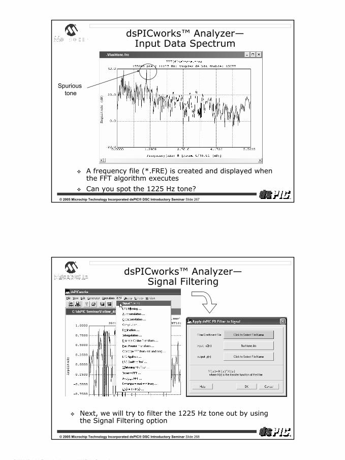
dsPIC® DSC Introductory Seminar
© 2004, Microchip Technology Incorporated, All Rights Reserved.
134
© 2005 Microchip Technology Incorporated dsPIC® DSC Introductory Seminar Slide 267
dsPICworks™ Analyzer—Input Data Spectrum
A frequency file (*.FRE) is created and displayed when the FFT algorithm executes
Can you spot the 1225 Hz tone?
Spurious tone
© 2005 Microchip Technology Incorporated dsPIC® DSC Introductory Seminar Slide 268
dsPICworks™ Analyzer—Signal Filtering
Next, we will try to filter the 1225 Hz tone out by using the Signal Filtering option
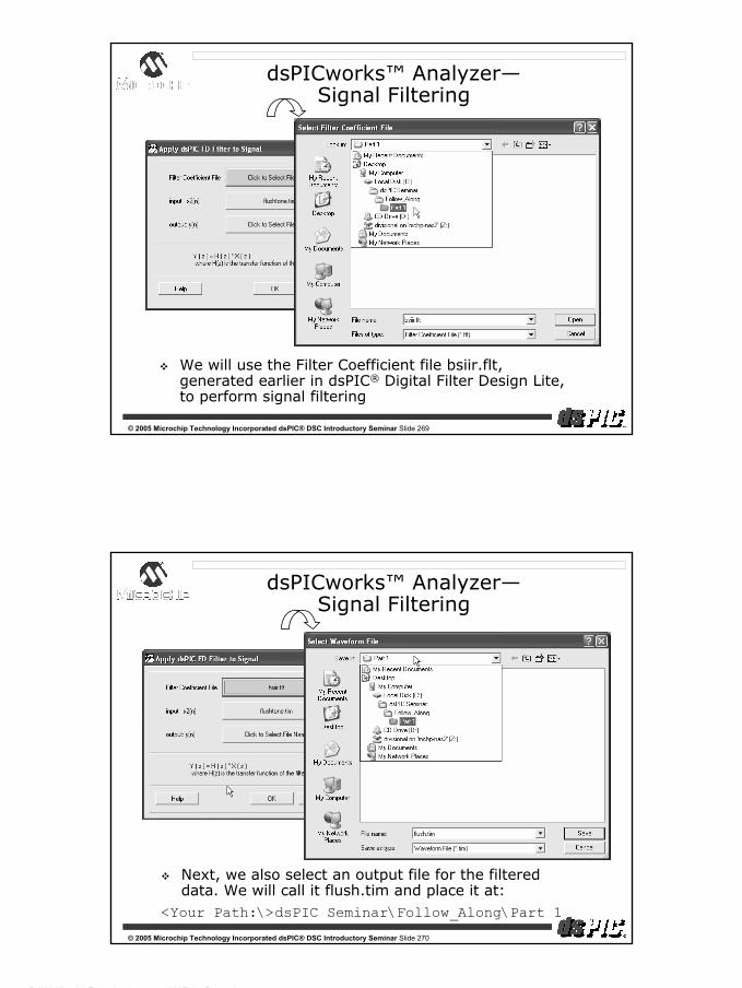
dsPIC® DSC Introductory Seminar
© 2004, Microchip Technology Incorporated, All Rights Reserved.
135
© 2005 Microchip Technology Incorporated dsPIC® DSC Introductory Seminar Slide 269
dsPICworks™ Analyzer—Signal Filtering
We will use the Filter Coefficient file bsiir.flt, generated earlier in dsPIC® Digital Filter Design Lite, to perform signal filtering
© 2005 Microchip Technology Incorporated dsPIC® DSC Introductory Seminar Slide 270
dsPICworks™ Analyzer—Signal Filtering
Next, we also select an output file for the filtered data. We will call it flush.tim and place it at:
<Your Path:\>dsPIC Seminar\Follow_Along\Part 1
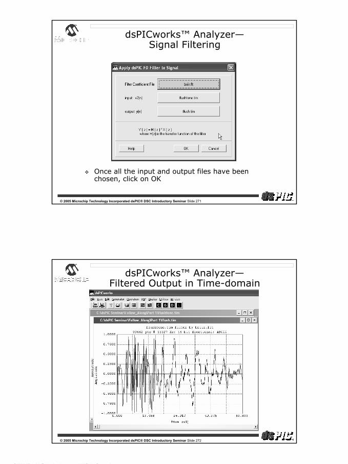
dsPIC® DSC Introductory Seminar
© 2004, Microchip Technology Incorporated, All Rights Reserved.
136
© 2005 Microchip Technology Incorporated dsPIC® DSC Introductory Seminar Slide 271
dsPICworks™ Analyzer—Signal Filtering
Once all the input and output files have been chosen, click on OK
© 2005 Microchip Technology Incorporated dsPIC® DSC Introductory Seminar Slide 272
dsPICworks™ Analyzer—Filtered Output in Time-domain

dsPIC® DSC Introductory Seminar
© 2004, Microchip Technology Incorporated, All Rights Reserved.
137
© 2005 Microchip Technology Incorporated dsPIC® DSC Introductory Seminar Slide 273
dsPICworks™ Analyzer—Computing FFT
Once again, we will compute an FFT
Use the filtered output time-domain file as input
Use all the defaults in the FFT Dialog and click OK
© 2005 Microchip Technology Incorporated dsPIC® DSC Introductory Seminar Slide 274
dsPICworks™ Analyzer—Input v/s Output Spectrum
Notice the effect of filtering on the tone at 1225 Hz
Filtered Output
Spectrum
Input Signal
Spectrum

dsPIC® DSC Introductory Seminar
© 2004, Microchip Technology Incorporated, All Rights Reserved.
138
© 2005 Microchip Technology Incorporated dsPIC® DSC Introductory Seminar Slide 275
dsPICworks™ Analyzer—Exporting Data
Next we will export the filtered output to a 16-bit WAV file
© 2005 Microchip Technology Incorporated dsPIC® DSC Introductory Seminar Slide 276
dsPICworks™ Analyzer—Exporting Data
Once the Export File dialog has been set up, click OK

dsPIC® DSC Introductory Seminar
© 2004, Microchip Technology Incorporated, All Rights Reserved.
139
© 2005 Microchip Technology Incorporated dsPIC® DSC Introductory Seminar Slide 277
dsPICworks™ Analyzer—WAV Playback
In Windows® Explorer, notice the new WAV file.
You may play this back on a Windows Media Player and notice the absence of the tonal component at 1225 Hz
Return to foil 148
WAV file containing filtered signal
© 2005 Microchip Technology Incorporated dsPIC® DSC Introductory Seminar Slide 278
Appendix F
Hands-on
PI Controller
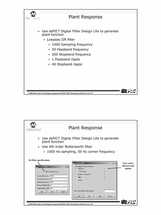
dsPIC® DSC Introductory Seminar
© 2004, Microchip Technology Incorporated, All Rights Reserved.
140
© 2005 Microchip Technology Incorporated dsPIC® DSC Introductory Seminar Slide 279
Plant Response
Use dsPIC® Digital Filter Design Lite to generate plant function
Lowpass IIR filter
1000 Sampling frequency
50 Passband frequency
200 Stopband frequency
1 Passband ripple
40 Stopband ripple
© 2005 Microchip Technology Incorporated dsPIC® DSC Introductory Seminar Slide 280
Plant Response
Use dsPIC® Digital Filter Design Lite to generate plant function
Use 4th order Butterworth filter
1000 Hz sampling, 50 Hz corner frequency
Set filter specificationsNext, select Butterworth
option.

dsPIC® DSC Introductory Seminar
© 2004, Microchip Technology Incorporated, All Rights Reserved.
141
© 2005 Microchip Technology Incorporated dsPIC® DSC Introductory Seminar Slide 281
dsPIC® Digital Filter Design
© 2005 Microchip Technology Incorporated dsPIC® DSC Introductory Seminar Slide 282
Plant Response
Generate code:
In dsPIC® Filter Design Lite select “Codegen-Microchip-dsPIC30” from pull down menu
Check:
“Use General Subroutine”
“C Header File”
“X Data Space”
Type in “Plant” as file name, the “.s” extension will be added automatically
Open the PID project and verify/add Plant.s to the PID project
<Your Path:\>dsPIC Seminar\Follow_Along\Part 2\PID.mcwBuild the project
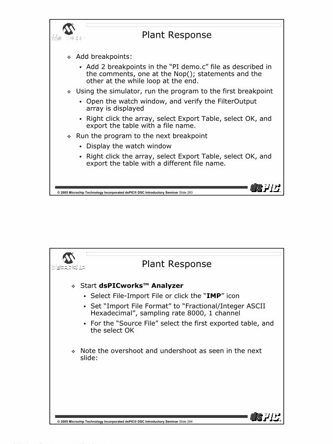
dsPIC® DSC Introductory Seminar
© 2004, Microchip Technology Incorporated, All Rights Reserved.
142
© 2005 Microchip Technology Incorporated dsPIC® DSC Introductory Seminar Slide 283
Plant Response
Add breakpoints:
Add 2 breakpoints in the “PI demo.c” file as described in the comments, one at the Nop(); statements and the other at the while loop at the end.
Using the simulator, run the program to the first breakpoint
Open the watch window, and verify the FilterOutputarray is displayed
Right click the array, select Export Table, select OK, and export the table with a file name.
Run the program to the next breakpoint
Display the watch window
Right click the array, select Export Table, select OK, and export the table with a different file name.
© 2005 Microchip Technology Incorporated dsPIC® DSC Introductory Seminar Slide 284
Plant Response
Start dsPICworks™ Analyzer
Select File-Import File or click the “IMP” icon
Set “Import File Format” to “Fractional/Integer ASCII Hexadecimal”, sampling rate 8000, 1 channel
For the “Source File” select the first exported table, and the select OK
Note the overshoot and undershoot as seen in the next slide:

dsPIC® DSC Introductory Seminar
© 2004, Microchip Technology Incorporated, All Rights Reserved.
143
© 2005 Microchip Technology Incorporated dsPIC® DSC Introductory Seminar Slide 285
dsPICworks™ Analyzer—Open Loop Response
© 2005 Microchip Technology Incorporated dsPIC® DSC Introductory Seminar Slide 286
Plant Response
In dsPICworks™ Analyzer
Select File-Import or click the “IMP” icon
Set “Import File Format” to “Fractional/Integer ASCII Hexadecimal”, sampling rate 8000, 1 channel
For the “Source File” select the second exported table, and the select OK
Note the overshoot and undershoot has been removed as seen in the next slide:
Go to Window->Graph Control->Y Direction->Zoom out to adjust the X/Y graph ratio

dsPIC® DSC Introductory Seminar
© 2004, Microchip Technology Incorporated, All Rights Reserved.
144
© 2005 Microchip Technology Incorporated dsPIC® DSC Introductory Seminar Slide 287
dsPICworks™ Analyzer—Closed Loop Response
© 2005 Microchip Technology Incorporated dsPIC® DSC Introductory Seminar Slide 288
Plant Response
In the “PI demo.c” file as described in the comments, remove the comments allowing the second set of PI gains to be used.
Rebuild the PID project
Using the simulator, run the program to the secondbreakpoint
Open the watch window, and verify the FilterOutputarray is displayed
Right click the array, select Export Table, select OK, and export the table with a different file name.

dsPIC® DSC Introductory Seminar
© 2004, Microchip Technology Incorporated, All Rights Reserved.
145
© 2005 Microchip Technology Incorporated dsPIC® DSC Introductory Seminar Slide 289
Plant Response
In dsPICworks™ Analyzer
Select File-Import or click the “IMP” icon
Set “Import File Format” to “Fractional/Integer ASCII Hexadecimal”, sampling rate 8000, 1 channel
For the “Source File” select the third exported table, and the select OK
Note the results of the bad PI tuning:
© 2005 Microchip Technology Incorporated dsPIC® DSC Introductory Seminar Slide 290
dsPICworks™ Analyzer—Bad PI Tuning

dsPIC® DSC Introductory Seminar
© 2004, Microchip Technology Incorporated, All Rights Reserved.
146
© 2005 Microchip Technology Incorporated dsPIC® DSC Introductory Seminar Slide 291
Plant Response
Note effectiveness of being able to choose the tuning values and perform software simulation to witness the effects of the PI variables
Return to foil 153
© 2005 Microchip Technology Incorporated dsPIC® DSC Introductory Seminar Slide 292
Thank You!

dsPIC® DSC Introductory Seminar
© 2004, Microchip Technology Incorporated, All Rights Reserved.
147
© 2005 Microchip Technology Incorporated dsPIC® DSC Introductory Seminar Slide 293
Trademarks & Disclaimers
The Microchip name and logo, the Microchip logo, Accuron, dsPIC, KEELOQ, microID, MPLAB, PIC, PICmicro, PICSTART, PRO MATE, PowerSmart, rfPIC, and SmartShunt are registered trademarks of Microchip Technology Incorporated in the U.S.A. and other countries.AmpLab, FilterLab, MXDEV, MXLAB, PICMASTER, SEEVAL, SmartSensor and The Embedded Control Solutions Company are registered trademarks of Microchip Technology Incorporated in the U.S.A.Analog-for-the-Digital Age, Application Maestro, dsPICDEM, dsPICDEM.net, dsPICworks, ECAN, ECONOMONITOR, FanSense, FlexROM, fuzzyLAB, In-Circuit Serial Programming, ICSP, ICEPIC, Migratable Memory, MPASM, MPLIB, MPLINK, MPSIM, PICkit, PICDEM, PICDEM.net, PICLAB, PICtail, PowerCal, PowerInfo, PowerMate, PowerTool, rfLAB, rfPICDEM, Select Mode, Smart Serial, SmartTel and Total Endurance are trademarks of Microchip Technology Incorporated in the U.S.A. and other countries.SQTP is a service mark of Microchip Technology Incorporated in the U.S.A.All other trademarks mentioned herein are property of their respective companies.© 2004, Microchip Technology Incorporated, Printed in the U.S.A., All Rights Reserved.
All rights reserved. Copyright © 2004 Microchip Technology Incorporated. Information contained in this publication regarding device applications and the like is intended through suggestion only and may be superseded by updates. No representation or warranty is given and no liability is assumed by Microchip Technology Incorporated with respect to the accuracy or use of such information, or infringement of patents or other intellectual property rights arising from such use or otherwise. Use of Microchip’s products as critical components in life support systems is not authorized except with express written approval by Microchip. No licenses are conveyed, implicitly or otherwise, under any intellectual property rights.