Embed Size (px)
Citation preview
igus® (UK) Ltd | Phone (01604) 677240 Fax -245 | [email protected] | www.igus.co.uk
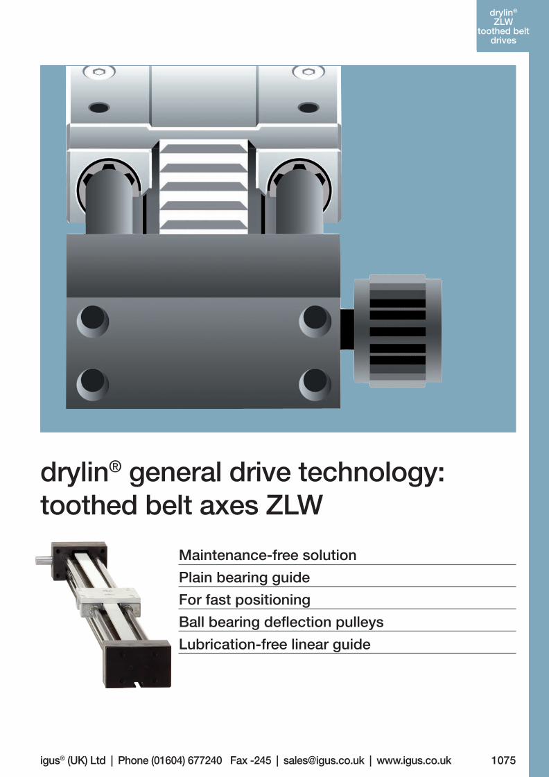
drylin® general drive technology: toothed belt axes ZLW
Maintenance-free solution
Plain bearing guide
For fast positioning
Ball bearing deflection pulleys
Lubrication-free linear guide
1075
drylin®
drivetechnology
Lifetime calculation, CAD files and much more support www.igus.co.uk/en/drylin-accessories
drylin®
ZLWtoothed belt
drives
06_GL6_UK_drylin_Antrieb.indd 69 26.02.13 10:49
1076 More information www.igus.co.uk/en/drylinZLW
drylin®
ZLWtoothed belt
drives drylin® ZLW | Toothed Belt Axes
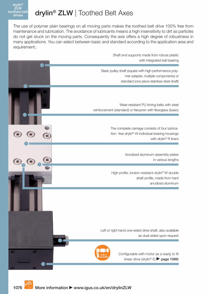
The use of polymer plain bearings on all moving parts makes the toothed belt drive 100% free from maintenance and lubrication. The avoidance of lubricants means a high insensitivity to dirt as particles do not get stuck on the moving parts. Consequently the axis offers a high degree of robustness in many applications. You can select between basic and standard according to the application area and requirement:.
Shaft end supports made from robust plastic
with integrated ball bearing
Basic pulley shaft (square with high performance poly-
mer adapter, multiple components) or
standard (one piece stainless steel shaft)
The complete carriage consists of four lubrica-
tion- free drylin® W individual bearing housings
with drylin® R liners
Anodized aluminum assembly plates
in various lengths
Wear-resistant PU timing belts with steel
reinforcement (standard) or Neopren with fiberglass (basic)
High profile, torsion-resistant drylin® W double
shaft profile, made from hard
anodized aluminum
Left or right hand one-sided drive shaft, also available
as dual-sided upon request
Configurable with motor as a ready to fit
linear drive (drylin® E) page 1089)drylin E
compatible®
06_GL6_UK_drylin_Antrieb.indd 70 26.02.13 10:49
1077igus® (UK) Ltd | Phone (01604) 677240 Fax -245 | [email protected] | www.igus.co.uk
drylin® ZLW | Toothed Belt Axesdrylin®
ZLWtoothed belt
drives
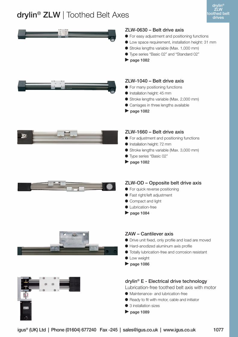
ZLW-0630 – Belt drive axis For easy adjustment and positioning functions
Low space requirement, installation height: 31 mm
Stroke lengths variable (Max. 1,000 mm)
Type series “Basic 02” and “Standard 02”
page 1082
ZLW-1040 – Belt drive axis For many positioning functions
Installation height: 45 mm
Stroke lengths variable (Max. 2,000 mm)
Carriages in three lengths available
page 1082
ZLW-1660 – Belt drive axis For adjustment and positioning functions
Installation height: 72 mm
Stroke lengths variable (Max. 3,000 mm)
Type series “Basic 02”
page 1082
ZLW-OD – Opposite belt drive axis For quick reverse positioning
Fast right/left adjustment
Compact and light
Lubrication-free
page 1084
ZAW – Cantilever axis Drive unit fixed, only profile and load are moved
Hard-anodized aluminum axis profile
Totally lubrication-free and corrosion resistant
Low weight
page 1086
drylin® E - Electrical drive technologyLubrication-free toothed belt axis with motor
Maintenance- and lubrication-free
Ready to fit with motor, cable and initiator
3 installation sizes
page 1089
06_GL6_UK_drylin_Antrieb.indd 71 26.02.13 10:49
1078
drylin®
ZLWtoothed belt
drives
Lifetime calculation, CAD files and much more support www.igus.co.uk/en/drylinZLW
drylin® ZLW | Toothed Belt Axes
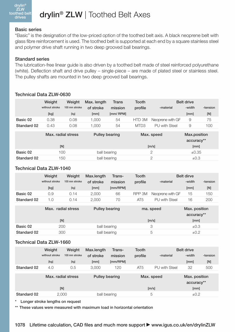
Basic series“Basic” is the designation of the low-priced option of the toothed belt axis. A black neoprene belt with glass fibre reinforcement is used. The toothed belt is supported at each end by a square stainless steel and polymer drive shaft running in two deep grooved ball bearings.
Standard seriesThe lubrication-free linear guide is also driven by a toothed belt made of steel reinforced polyurethane (white). Deflection shaft and drive pulley – single-piece – are made of plated steel or stainless steel. The pulley shafts are mounted in two deep grooved ball bearings.
Max. radial stress Pulley bearing ma. speed Max. position
accuracy**[N] [m/s] [mm]
Basic 02 200 ball bearing 3 ±0.3
Standard 02 300 ball bearing 5 ±0.2
Weight Weight Max.length Trans- Tooth Belt dirvewithout stroke 100 mm stroke of stroke mission profile -material -width -tension
[kg] [kg] [mm] [mm/RPM] [mm] [N]
Basic 02 0.9 0.14 2,000 66 RPP 3M Neoprene with GF 15 150
Standard 02 1.0 0.14 2,000 70 AT5 PU with Steel 16 200
Weight Weight Max. length Trans Tooth Belt drivewithout stroke 100 mm stroke of stroke mission profile -material -width -tension
[kg] [kg] [mm] [mm/ RPM] [mm] [N]
Basic 02 0.38 0.08 1,000 54 HTD 3M Neoprene with GF 9 75
Standard 02 0.43 0.08 1,000 54 MTD3 PU with Steel 9 100
Max. radial stress Pulley bearing Max. speed Max.position
accuracy**[N] [m/s] [mm]
Basic 02 100 ball bearing 2 ±0.35Standard 02 150 ball bearing 2 ±0.3
Technical Data ZLW-0630
* Longer stroke lengths on request
** These values were measured with maximum load in horizontal orientation
Technical Data ZLW-1040
Max. radial stress Pulley bearing Max. speed Max. position
accuracy**[N] [m/s] [mm]
Standard 02 2,000 ball bearing 5 ±0.2
Weight Weight Max.length Trans- Tooth Belt drivewithout stroke 100 mm stroke of stroke mission profile -material -width -tension
[kg] [kg] [mm] [mm/RPM] [mm] [N]
Standard 02 4.0 0.5 3,000 120 AT5 PU with Steel 32 500
Technical Data ZLW-1660
06_GL6_UK_drylin_Antrieb.indd 72 26.02.13 10:49
1079igus® (UK) Ltd | Phone (01604) 677240 Fax -245 | [email protected] | www.igus.co.ukLifetime calculation, CAD files and much more support www.igus.co.uk/en/drylinZLW
drylin®
ZLWtoothed belt
drivesdrylin® ZLW-0630 | Technical Data
0 2 4 6 8
0.0
0.2
0.4
0.6
0.8
1.2
1.0
0.2
0.4
0.6
0.8
1.0
0.0
0 1 2 3 74 5 6
0.2
0.4
0.6
0.8
1.2
1.0 2.5 5.0 7.5 10
1.0
0.0
0.2
0.4
0.6
0.8
1.0
1.2
20 4 6 8
0.5300200150100500
1.0
2.0
4.0
4.5
5.0
2.5
3.0
3.5
1.5
250
0.1 mm
0.3 mm 0.5 mm 1.0 mm
0
20
700 800 900 1,000 1,200600500
40
60
80
100
120
1,100
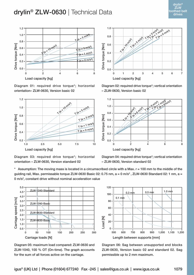
* Assumption: The moving mass is located in a circumscribed circle with a Max. r = 100 mm to the middle of the
guiding rail, Max. permissable torque ZLW-0630 Basic 02: 0.75 nm, a = 0 m/s2 , ZLW-0630 Standard 02: 1 nm, a =
0 m/s2, constant drive without nominal acceleration value
Diagram 01: required drive torque*; horizontal
orientation– ZLW-0630, Version basic 02
Dri
ve t
orq
ue [N
m]
Load capacity [kg]
Diagram 02: required drive torque*; vertical orientation
– ZLW-0630, Version basic 02
Dri
ve t
orq
ue [N
m]
Load capacity [kg]
Diagram 03: required drive torque*; horizontal
orientation – ZLW-0630, Version standard 02
Dri
ve t
orq
ue [N
m]
Load capacity [kg]
Diagram 04: required drive torque*; vertical orientation
– ZLW-0630, Version standard 02
Dri
ve t
orq
ue [N
m]
Load capacity [kg]
Diagram 05: maximum load compared: ZLW-0630 and
ZLW-1040, 100 % OT (On-time). The graph accounts
for the sum of all forces active on the carriage.
Car
riag
e sp
eed
[m/s
]
Carriage loads [N]
Diagram 06: Sag between unsupported end blocks
ZLW-0630, Version basic 02 and standard 02. Sag
permissible up to 2 mm maximum.
Load
[N]
Length between supports [mm]
06_GL6_UK_drylin_Antrieb.indd 73 26.02.13 10:49
1080 Lifetime calculation, CAD files and much more support www.igus.co.uk/en/drylinZLW
drylin®
ZLWtoothed belt
drives drylin® ZLW-1040 | Technical Data
1 5 10 15 20
0.2
1.0
1.2
1.4
1.8
1.6
0.4
0.6
0.8
0.4
0.6
0.8
1.0
1.2
1.4
1.6
1.8
0.2
0 4 8 102 6
0.0
1.0
1.5
2.0
2.5
0 5 10 15 20 25
0.5
0.0
0.5
1.0
1.5
2.0
2.5
50 10 15
0.5300200150100500
1.0
2.0
4.0
4.5
5.0
2.5
3.0
3.5
1.5
250
0900 1,100 1,300 1,500 1,700 1,900 2,100700500
50
100
150
200
250
300
350
0.1 mm0.2 mm
0.5 mm1.0 mm 2.0 mm
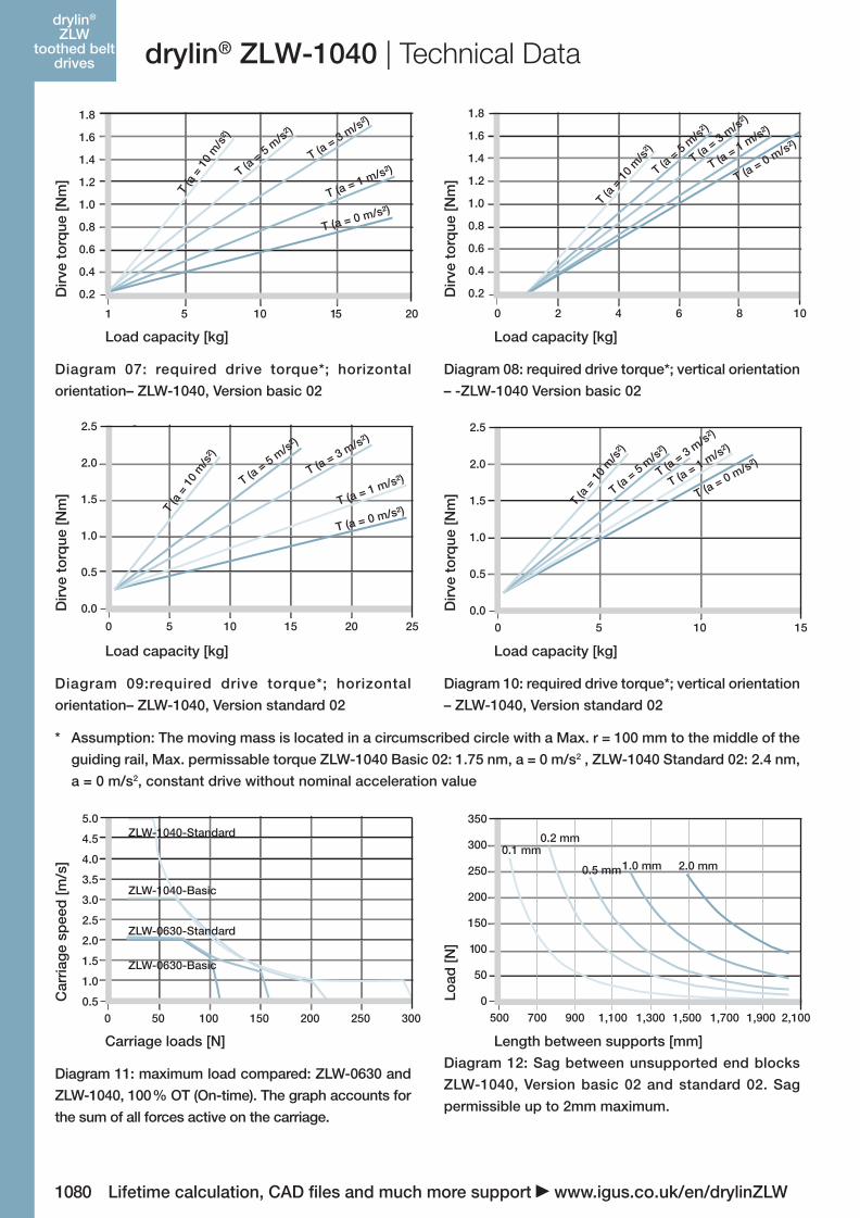
* Assumption: The moving mass is located in a circumscribed circle with a Max. r = 100 mm to the middle of the
guiding rail, Max. permissable torque ZLW-1040 Basic 02: 1.75 nm, a = 0 m/s2 , ZLW-1040 Standard 02: 2.4 nm,
a = 0 m/s2, constant drive without nominal acceleration value
Diagram 07: required drive torque*; horizontal
orientation– ZLW-1040, Version basic 02
Dir
ve t
orq
ue [N
m]
Load capacity [kg]
Diagram 08: required drive torque*; vertical orientation
– -ZLW-1040 Version basic 02
Dir
ve t
orq
ue [N
m]
Load capacity [kg]
Diagram 09:required drive torque*; horizontal
orientation– ZLW-1040, Version standard 02
Dir
ve t
orq
ue [N
m]
Load capacity [kg]
Diagram 10: required drive torque*; vertical orientation
– ZLW-1040, Version standard 02
Dir
ve t
orq
ue [N
m]
Load capacity [kg]
Diagram 11: maximum load compared: ZLW-0630 and
ZLW-1040, 100 % OT (On-time). The graph accounts for
the sum of all forces active on the carriage.
Car
riag
e sp
eed
[m/s
]
Carriage loads [N]
Diagram 12: Sag between unsupported end blocks
ZLW-1040, Version basic 02 and standard 02. Sag
permissible up to 2mm maximum.
Load
[N]
Length between supports [mm]
06_GL6_UK_drylin_Antrieb.indd 74 26.02.13 10:49
1081igus® (UK) Ltd | Phone (01604) 677240 Fax -245 | [email protected] | www.igus.co.ukLifetime calculation, CAD files and much more support www.igus.co.uk/en/drylinZLW
drylin®
ZLWtoothed belt
drivesMy Sketches
06_GL6_UK_drylin_Antrieb.indd 75 26.02.13 10:49
1082 Lifetime calculation, CAD files and much more support www.igus.co.uk/en/drylinZLW
drylin®
ZLWtoothed belt
drives drylin® ZLW | Delivery Program
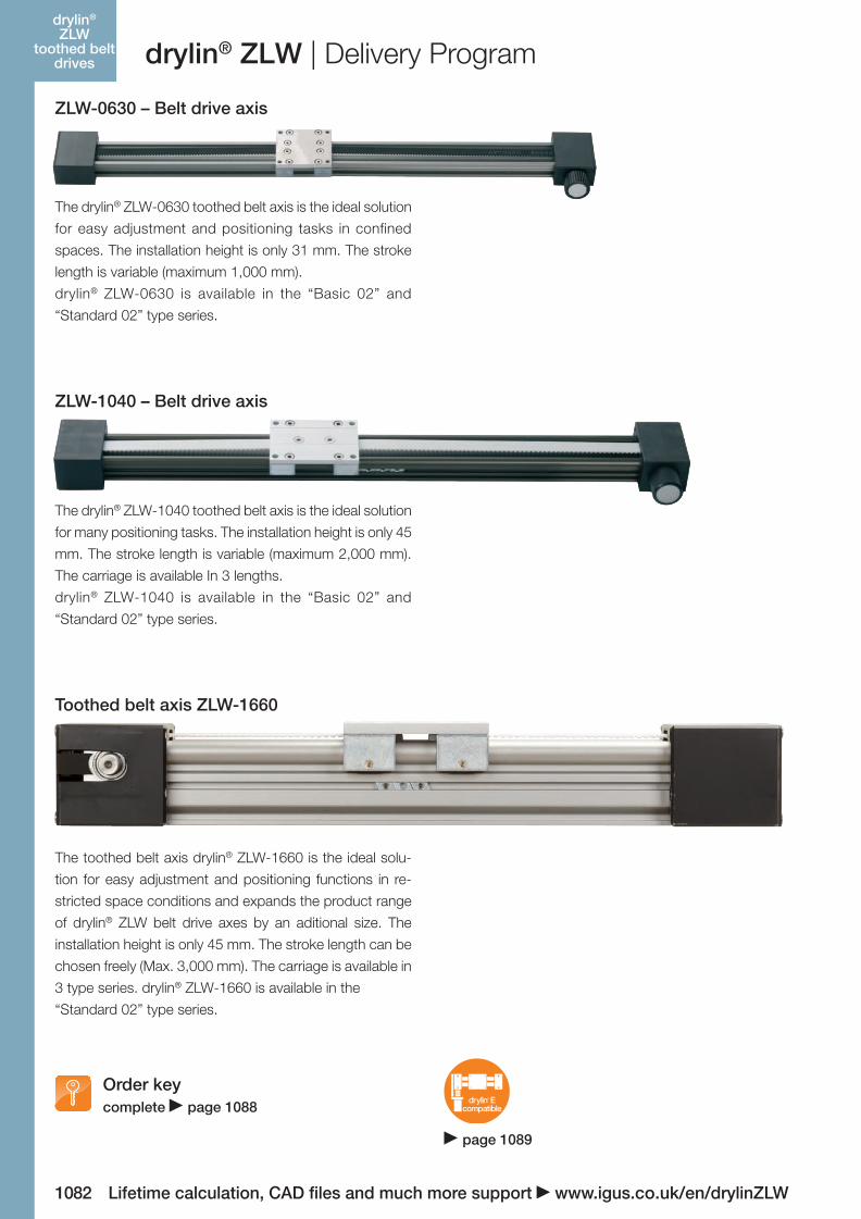
ZLW-0630 – Belt drive axis
The drylin® ZLW-0630 toothed belt axis is the ideal solution
for easy adjustment and positioning tasks in confined
spaces. The installation height is only 31 mm. The stroke
length is variable (maximum 1,000 mm).
drylin® ZLW-0630 is available in the “Basic 02” and
“Standard 02” type series.
ZLW-1040 – Belt drive axis
The drylin® ZLW-1040 toothed belt axis is the ideal solution
for many positioning tasks. The installation height is only 45
mm. The stroke length is variable (maximum 2,000 mm).
The carriage is available In 3 lengths.
drylin® ZLW-1040 is available in the “Basic 02” and
“Standard 02” type series.
Toothed belt axis ZLW-1660
The toothed belt axis drylin® ZLW-1660 is the ideal solu-
tion for easy adjustment and positioning functions in re-
stricted space conditions and expands the product range
of drylin® ZLW belt drive axes by an aditional size. The
installation height is only 45 mm. The stroke length can be
chosen freely (Max. 3,000 mm). The carriage is available in
3 type series. drylin® ZLW-1660 is available in the
“Standard 02” type series.
Order keycomplete page 1088
drylin Ecompatible
®
page 1089
06_GL6_UK_drylin_Antrieb.indd 76 26.02.13 10:49
igus® (UK) Ltd | Phone (01604) 677240 Fax -245 | [email protected] | www.igus.co.uk 1083Lifetime calculation, CAD files and much more support www.igus.co.uk/en/drylinZLW
drylin®
ZLWtoothed belt
drivesdrylin® ZLW | Delivery Program
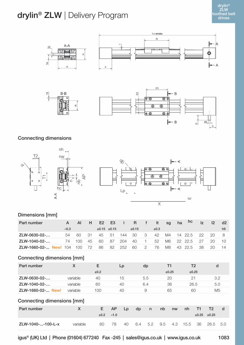
Part number
A AI H E2 E3 l R f lt sg ha hc lz l2 d2–0.3 ±0.15 ±0.15 ±0.15 ±0.3 h9
ZLW-0630-02-… 54 60 31 45 51 144 30 3 42 M4 14 22.5 22 20 8
ZLW-1040-02-… 74 100 45 60 87 204 40 1 52 M6 22 22.5 27 20 10
ZLW-1660-02-... New! 104 100 72 86 82 252 60 2 76 M8 43 22.5 38 20 14
Part number
X E Lp dp T1 T2 d±0.2 ±0.25 ±0.25
ZLW-0630-02-… variable 40 15 5.5 20 21 3.2
ZLW-1040-02-… variable 60 40 6.4 36 26.5 5.0
ZLW-1660-02-... New! variable 100 40 9 65 60 M5
Dimensions [mm]
Connecting dimensions [mm]
Connecting dimensions [mm]
Part number
X E AP Lp dp n nb nw nh T1 T2 d±0.2 –1.0 ±0.25 ±0.25
ZLW-1040-...-100-L-x variable 60 78 40 6.4 5.2 9.5 4.3 15.5 36 26.5 5.0
Connecting dimensions
Lp
X
dp
E
T2
hc
nh
T1
n
nw
nbA
P
d
Lp
X
dp
E
T2
hc
nh
T1
n
nw
nbA
P
d
06_GL6_UK_drylin_Antrieb.indd 77 26.02.13 10:49
1084
prices delivery time
Lifetime calculation, CAD files and much more support www.igus.co.uk/en/drylinZLW
price list onlinewww.igus.co.uk/en/drylinZLW
2-3 days
drylin®
ZLWtoothed belt
drives drylin® ZLW | Delivery Program
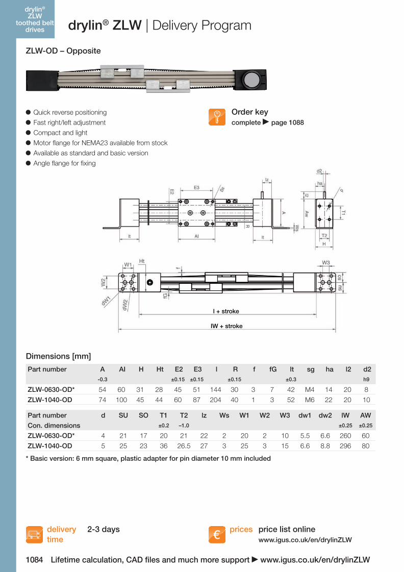
Part number A AI H Ht E2 E3 l R f fG lt sg ha l2 d2-0.3 ±0.15 ±0.15 ±0.15 ±0.3 h9
ZLW-0630-OD* 54 60 31 28 45 51 144 30 3 7 42 M4 14 20 8
ZLW-1040-OD 74 100 45 44 60 87 204 40 1 3 52 M6 22 20 10
Part number
Con. dimensions
d SU SO T1 T2 lz Ws W1 W2 W3 dw1 dw2 lW AW±0.2 –1.0 ±0.25 ±0.25
ZLW-0630-OD* 4 21 17 20 21 22 2 20 2 10 5.5 6.6 260 60
ZLW-1040-OD 5 25 23 36 26.5 27 3 25 3 15 6.6 8.8 296 80
l + stroke
IW + stroke
* Basic version: 6 mm square, plastic adapter for pin diameter 10 mm included
ZLW-OD – Opposite
Quick reverse positioning
Fast right/left adjustment
Compact and light
Motor flange for NEMA23 available from stock
Available as standard and basic version
Angle flange for fixing
Dimensions [mm]
Order keycomplete page 1088
06_GL6_UK_drylin_Antrieb.indd 78 26.02.13 10:49
1085
prices deliverytime
igus® (UK) Ltd | Phone (01604) 677240 Fax -245 | [email protected] | www.igus.co.ukLifetime calculation, CAD files and much more support www.igus.co.uk/en/drylinZLW
price list onlinewww.igus.co.uk/en/drylinZLW
2-3 days
drylin®
ZLWtoothed belt
drivesdrylin® ZLW | Delivery Program
Order keycomplete page 1088
Einheit ZLW-1040-LT ZLW-1040-UWfor cold storage for under water use
Weight without stroke kg 1.0 1.0
Weight 100 mm stroke kg 0.14 0.14
Max. length of stroke mm 2,000 1,000
Transmission mm/U 70 70
Gear Teeth AT 5 AT 5
Belt drive -material TPUKF2 PU + stainless steel-reinforcement
-width mm 16 16
-tension N 200 50
Max. radial load N 300 100
Guide bearing steel ball bearing xiros®-ball bearing
Max. speed m/s 5 1
position variants of carriage mm ±0.2 ±0.5
load dependent
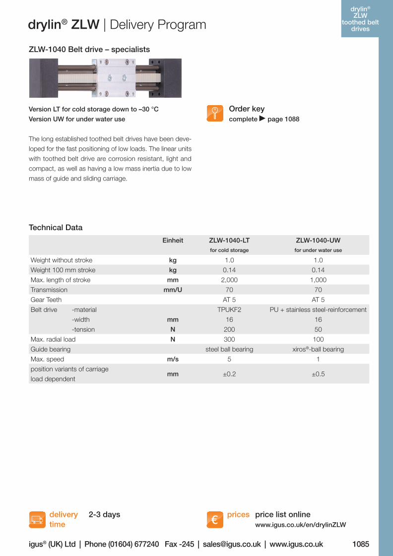
ZLW-1040 Belt drive – specialists
Version LT for cold storage down to –30 °C
Version UW for under water use
The long established toothed belt drives have been deve-
loped for the fast positioning of low loads. The linear units
with toothed belt drive are corrosion resistant, light and
compact, as well as having a low mass inertia due to low
mass of guide and sliding carriage.
Technical Data
06_GL6_UK_drylin_Antrieb.indd 79 26.02.13 10:49
1086
prices delivery time
price list onlinewww.igus.co.uk/en/drylinZLW
Lifetime calculation, CAD files and much more support www.igus.co.uk/en/drylinZLW
8-14 days
drylin®
ZLWtoothed belt
drives drylin® ZLW | Delivery Program
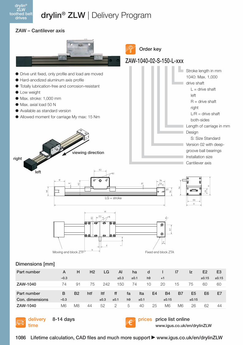
Stroke length in mm
1040: Max. 1,000
drive shaft
L = drive shaft
left
R = drive shaft
right
L/R = drive shaft
both-sides
Length of carriage in mm
Design
S: Size Standard
Version 02 with deep-
groove ball bearings
Installation size
Cantilever axis
Order key
ZAW-1040-02-S-150-L-xxx
ZAW – Cantilever axis
Al
ltf
htf
E2
E3
E2
H2
B2
B
ff
lz
ld
ha
H
A
E5
E6
E7
l7
E4
B4
B7
ltalta
fa
Al
ltf
htf
E2
E3
E2
H2
B2
B
ff
lz
ld
ha
H
AE5
E6
E7
l7
E4
B4
B7
lta
lta
fa
Al
ltf
htf
E2
E3
E2
H2
B2
B
ff
lz
ld
ha
H
A
E5
E6
E7
l7
E4
B4
B7
lta
lta
fa
LG + stroke
Fixed end block ZTAMoving end block ZTF
Dimensions [mm]
Drive unit fixed, only profile and load are moved
Hard-anodized aluminum axis profile
Totally lubrication-free and corrosion-resistant
Low weight
Max. stroke: 1,000 mm
Max. axial load 50 N
Available as standard version
Allowed moment for carriage My max: 15 Nm
viewing directionright
left
Part number A H H2 LG Al ha d l l7 lz E2 E3–0.3 ±0.3 ±0.1 h9 +1 ±0.15 ±0.15
ZAW-1040 74 91 75 242 150 74 10 20 15 75 60 60
Part number
Con. dimensions
B B2 htf ltf ff fa lta E4 B4 B7 E5 E6 E7–0.3 ±0.3 ±0.1 h9 ±0.1 ±0.15 ±0.15
ZAW-1040 M6 M8 44 52 2 5 40 25 M6 M6 26 62 44
06_GL6_UK_drylin_Antrieb.indd 80 26.02.13 10:49
1087
prices deliverytime
igus® (UK) Ltd | Phone (01604) 677240 Fax -245 | [email protected] | www.igus.co.ukLifetime calculation, CAD files and much more support www.igus.co.uk/en/drylinZLW
price list onlinewww.igus.co.uk/en/drylinZLW
2-3 days
drylin®
ZLWtoothed belt
drivesdrylin® ZLW | Accessories | Delivery Program
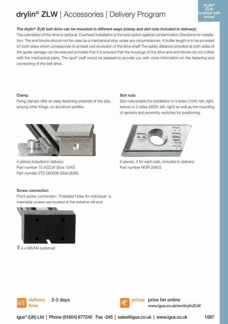
Clamp
Fixing clamps offer an easy fastening potential of the axis,
among other things, on aluminum profiles
Slot nuts
Slot nuts enable the installation in 3 sides (1040: left, right,
below) or 2 sides (0630: left, right) as well as the mounting
of sensors and proximity switches for positioning.
4 pieces included in delivery:
Part number 75.40ZLW (Size 1040)
Part number ZTZ-063006 (Size 0630)
8 pieces, 4 for each side, included in delivery:
Part number NOR-20602
Screw connection
Front screw connection: Threaded holes for individual- ly
insertable screws are located at the extreme rail end
4 x M6/M4 (optional)
The drylin® ZLW belt drive can be mounted in different ways (clamp and slot nuts included in delivery):
The orientation of the drive is optional. Overhead installation is the best option against contamination.Directions for installa-
tion: The end blocks should not be used as a mechanical stop under any circumstances. A buffer length is to be provided
on both sides which corresponds to at least one revolution of the drive shaft The safety distance provided at both sides of
the guide carriage can be reduced provided that it is ensured that the housings of the drive and end blocks do not collide
with the mechanical parts. The igus® staff would be pleased to provide you with more information on the fastening and
connecting of the belt drive.
06_GL6_UK_drylin_Antrieb.indd 81 26.02.13 10:49
1088
drylin® SHT- Linear-
achsen
Lifetime calculation, CAD files and much more support www.igus.co.uk/en/drylinZLW
x
1 2
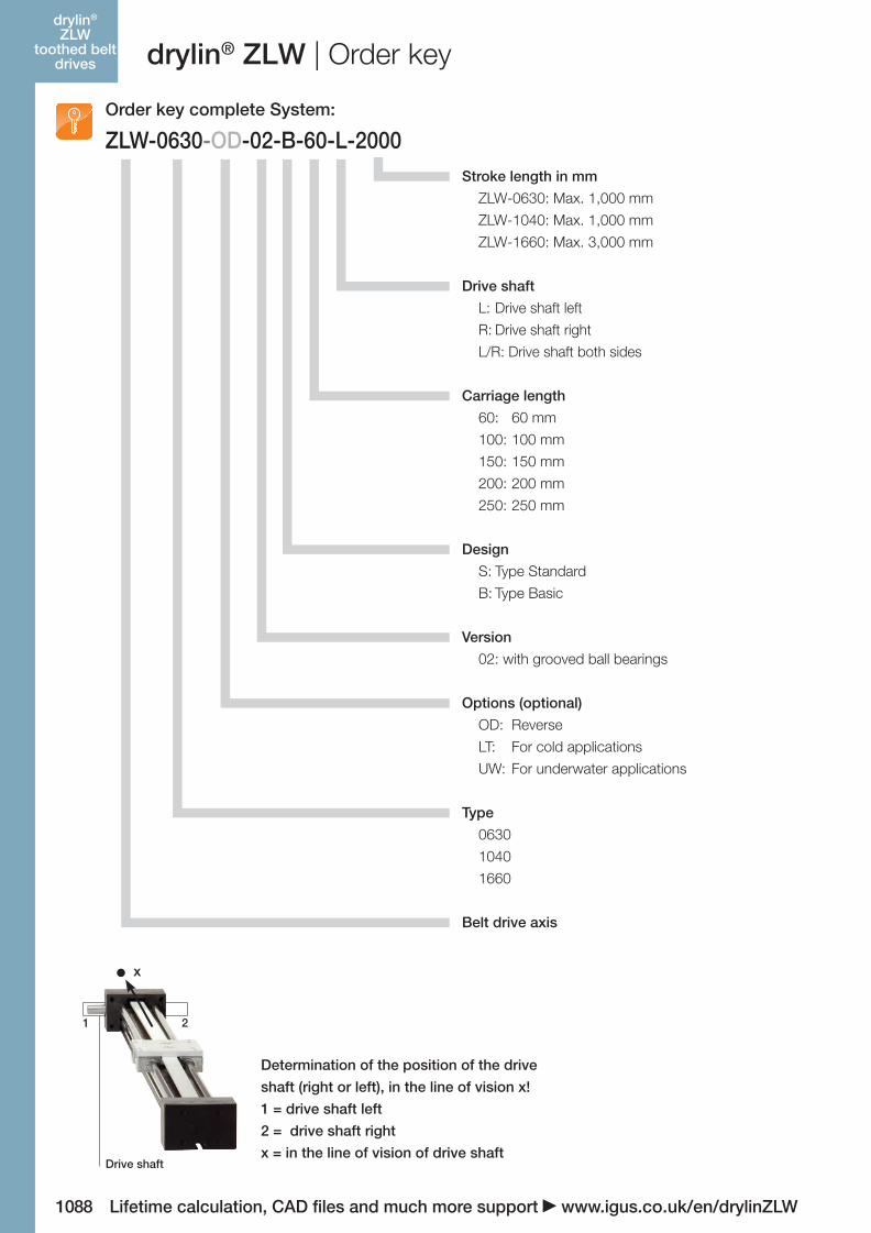
Drive shaft
Determination of the position of the drive
shaft (right or left), in the line of vision x!
1 = drive shaft left
2 = drive shaft right
x = in the line of vision of drive shaft
drylin® ZLW | Order keydrylin®
ZLWtoothed belt
drives
ZLW-0630-OD-02-B-60-L-2000Order key complete System:
Stroke length in mm
ZLW-0630: Max. 1,000 mm
ZLW-1040: Max. 1,000 mm
ZLW-1660: Max. 3,000 mm
Drive shaft
L: Drive shaft left
R: Drive shaft right
L/R: Drive shaft both sides
Carriage length
60: 60 mm
100: 100 mm
150: 150 mm
200: 200 mm
250: 250 mm
Design
S: Type Standard
B: Type Basic
Version
02: with grooved ball bearings
Options (optional)
OD: Reverse
LT: For cold applications
UW: For underwater applications
Type
0630
1040
1660
Belt drive axis
06_GL6_UK_drylin_Antrieb.indd 82 26.02.13 10:49