Embed Size (px)
Citation preview


Driver’s HandbookMack EPA2010 Emissions Operator’s Manual

ForewordThis manual contains information concerning the operation and functionof the Mack Engines. Please keep this manual in the vehicle at all times.
Note: Illustrations in this manual are used for reference only and maydiffer slightly from the actual vehicle. However, key componentsaddressed in this document are represented as accurately as possible.
The National Highway Traffic Safety Administration (NHTSA) andMack Trucks, Inc. should be informed immediately if you believe thatthe vehicle has a defect that could cause a crash, injury or death.
Contact NHTSA by calling the Auto Safety Hotline at 1 (888) 327-4236,by writing to NHTSA, U.S. Department of Transportation, Washington,DC 20590, by TTY at 1 (800) 424-9153, or visit their website atwww.nhtsa.dot.gov.
Mack Trucks, Inc.Greensboro, NC USA
Order number: PV776-21414253
© 2009Mack Trucks, Inc., Greensboro, NC USA
All rights reserved. No part of this publication may be reproduced,stored in retrieval system, or transmitted in any forms by any means,electronic, mechanical, photocopying, recording or otherwise, withoutthe prior written permission ofMack Trucks, Inc.

ContentsOverview of the Mack Engines ........................................................ 1
Introduction ...................................................................................... 1Fuel ................................................................................................... 2Bio Diesel ......................................................................................... 2Engine Oil ......................................................................................... 2Engine Operation .............................................................................. 3Engine Overview, MP7 and MP8 Left Side View ............................ 5Engine Overview, MP7 and MP8 Right Side View .......................... 6Engine Overview, MP10 Left Side View ......................................... 7Engine Overview,MP10 Right Side View ........................................ 8
Mack, EPA2010 Emissions Solution................................................ 9Exhaust Aftertreatment System ........................................................ 9
Safety Information ......................................................................... 11Exhaust Aftertreatment System Components and Operation ........ 12
Selective Catalytic Reduction (SCR) .......................................... 12Diesel Exhaust Fluid (DEF) ........................................................ 14Aftertreatment Control Module (ACM) ...................................... 15Aftertreatment Diesel Particulate Filter (DPF) ............................ 16Exhaust Aftertreatment System Operation .................................. 17
Driver Warnings and On Board Diagnostics (OBD) ...................... 25On Board Diagnostics (OBD) ...................................................... 25Instrument Cluster ....................................................................... 25Malfunction Indicator Lamp (MIL) ............................................. 27Aftertreatment DEF Tank Level - Driver Warning &Inducement .................................................................................. 28Aftertreatment DEF Quality - Driver Warning & Inducement .... 29Misfilling Diesel or Aftertreatment DEF Tanks .......................... 30SCR Tampering - Driver Warning & Inducement ....................... 31Ambient Air Temperature (AAT) ................................................ 32
Warranty and Maintenance ............................................................ 33Exhaust Aftertreatment System Maintenance ............................. 33Emissions Maintenance ............................................................... 33Engine Maintenance Intervals ..................................................... 33Oil Change Intervals .................................................................... 35Emissions Control System Warranty ........................................... 36


Safety InformationIMPORTANT: Before driving this vehicle, be certain that you have read and that youfully understand each and every step of the driving and handling information in thismanual. Be certain that you fully understand and follow all safety warnings.
IT IS IMPORTANT THAT THE FOLLOWING INFORMATION BE READ,UNDERSTOOD AND ALWAYS FOLLOWED.The following types of advisories are used throughout this manual:
DANGER
Danger indicates an unsafe practice that could result in serious personal injury or death.A danger advisory banner is inwhite type on ablack background with ablack border.
WARNING
Warning indicates an unsafe practice that could result in personal injury. A warningadvisory banner is inblack type on agray background with ablack border.
CAUTION
Caution indicates an unsafe practice that could result in damage to the product. A cautionadvisory is inblack type on awhite background with ablack border.
Note: Note indicates a procedure, practice, or condition that must be followed in order forthe vehicle or component to function in the manner intended.

CALIFORNIA PROPOSITION 65 WARNINGDiesel engine exhaust and some of its constituents are known to the State of California tocause cancer, birth defects and other reproductive harm.
CALIFORNIA PROPOSITION 65 WARNINGBattery posts, terminals and other related accessories contain lead and lead compounds,chemical known to the State of California to cause cancer and other reproductive harm.Batteries also contain other chemicals known to the State of California to cause cancer.Wash hands after handling.
ImportantYour new Mack truck contains many new technological advancements that may require newservicing techniques and methods. An authorized Mack truck dealer is in the best positionto provide technicians who have the necessary training, experience and tools to properlyservice your truck.
Overview of the Mack Engines 1
IntroductionIn 2010, the Mack engine family will consistof three engines: MP7, MP8 and MP10.The Mack engines meet the very stringentnew emissions standards which apply toall heavy-duty diesel engines built afterJanuary 1, 2010 for on-highway trucks. Thenew standards for EPA2010 requires 83%reduction in nitrogen oxide (NOx) and 0%reduction in Particles (Pt) relative to US07.
Key Features of the Mack Engines:
• Improved Fuel Economy• Extended Oil Drain Intervals• Improved Cooling Capacity• Low Maintenance Catalyzed
Aftertreatment Diesel Particulate Filter(DPF)
• Enhanced Engine Brake Performance• Selective Catalytic Reduction (SCR)

2 Overview of the Mack Engines
Fuel
CAUTION
Diesel engines for 2010 and later modelyear vehicles are designed to operate onlywith Ultra Low Sulfur Diesel (ULSD)fuel. Use of fuel other than ULSD willreduce the efficiency and durability of theengine, permanently damage the advancedemission control systems, reduce fueleconomy and possibly prevent the enginefrom running at all. Manufacturer’swarranties are likely to be rendered voidby usage of improper or incorrect fuel,and usage of fuels other than ULSD fuelin diesel-powered vehicles is illegal andpunishable with civil penalties. Use offuel additives to compensate for the lowersulfur content is NOT recommended byMack Trucks, Inc..
Fuel sold for use in diesel-powered enginesfor 2010 and later model year vehicles mayonly contain a maximum sulfur content of0.0015% by weight. This was done to reduceparticle emissions in the exhaust.
Bio DieselThe only BioDiesel Fuel approved by MackTrucks, Inc. for use in Mack Engines is SoyMethyl Ester (SME or SOME) in blends upto B5 Concentration (5% blend).
Note: Although higher concentrations areavailable, concentration up to B5 (maximum)are the only blends currently approved byMack Trucks, Inc.
Engine OilEO-O Premium Plus (or VDS-4) dieselengine oil is mandatory for use in all 2010emission compliant Mack engines. Chassisequipped with a 2010 emission compliantengine, which can be identified by the
presence of an Aftertreatment SelectiveCatalytic Reduction (SCR) system, alsorequire the use of Ultra Low Sulfur Diesel(ULSD) fuel. EO-O Premium Plus oilsexceed the new API service category CJ-4.

Overview of the Mack Engines 3
Engine Operation
DANGER
Do not use ether or other combustiblestarting aids in any Mack engine.Introduction of ether or similar startingaids could cause a fire or explosionresulting in severe property damage,serious personal injury or death.
CAUTION
DO NOT crank the engine for more than30 seconds at a time; wait 15 minutesafter each try to allow the starter to cool.Failure to follow these instructions couldcause starter damage.
Note: Some starters are equipped withstarter protection. If the engine is running,the starter temperature is too high, thetransmission is not in neutral or the clutchpedal is not depressed, starter engagementis inhibited.
Allow the engine to slow down and idle for3 to 5 minutes before shutting it off. Thisallows the turbocharger to cool down and thecooling system to dissipate the engine heat.Switch the engine off by turning the ignitionkey to the OFF position.
CAUTION
Shutting off an engine immediately afterhigh speed or full load operation candamage the turbocharger and cause heatstress in the engine. Always let the engineidle for 3 to 5 minutes before shutting itoff.
Mack Trucks, Inc. does not recommendthe use of winterfronts, shutters or anyother shield in front of the grille or radiatorpackage under normal circumstances.Today’s electronically controlled enginesare designed to operate in cold temperatureswithout a winterfront. These devices, ifnot used properly, can cause higher exhaustgas temperatures, power loss, excessive fanusage, failure of the charge-air-cooler anda reduction in fuel economy. Winterfrontscan be used in the wintertime during verycold weather if used properly. In these cases,engine coolant and intake air temperaturesmust also be carefully monitored andcontrolled. Please see your authorizedMack Truck dealer for Mack recommendedwinterfronts.
CAUTION
Mack is now using the ambient airtemperature (AAT) sensor for OBDmonitoring. If a customer installs awinterfront or blocks the radiator openingand blocks airflow to the sensor, they willlikely set an OBD diagnostic trouble code(DTC) for inaccurate sensor data due torestricted airflow across the sensor.

4 Overview of the Mack Engines
Engine Shutdown System
DANGER
Failure to take the necessary precautionswhen the STOP telltale is on can result inautomatic engine shutdown and the loss ofpower steering. Vehicle crash can occur.
The engine shutdown system willautomatically derate or stop the engine whenone or more of the conditions listed belowreaches a critical stage:
• High Engine Coolant Temperature(ECT)
• Low Engine Oil Pressure (EOP)• Low Engine Coolant Level (ECL)• High Crankcase Pressure (CCP)
When the shutdown is activated, the telltalescome on along with display symbols and thebuzzer is also activated. After a brief time,the engine shuts down. Find a safe place topull off the road as soon as possible.
After the engine has been shut down bythe system, turn the ignition key to the offposition. If necessary, the engine can berestarted for a brief time so that the vehiclemay be pulled off the road.
The alarm will remain activated until repairshave been made to correct the problem thatcaused the shutdown.
CAUTION
Continuously restarting the engine oncethe shutdown system is active may resultin severe engine damage.
Refer to the Driver Information Displaymanual for information about the displaysymbols.
W3031624

Overview of the Mack Engines 5
Engine Overview, MP7 and MP8 Left Side View
W2006034
MP8 Engine Shown, MP7 Engine Similar
1. Breather Tube 9. Fuel Filter
2. Intake Manifold 10. Hand-Priming Pump
3. Air Compressor 11. Crankcase Ventilator
4. Power Steering Pump 12. Alternator
5. Fuel Pump 13. AC Compressor
6. Engine Control Module (ECM) 14. Alternator/AC Compressor Belt
7. Fuel Filter 15. Fan/Coolant Pump Belt
8. Fuel/Water Separator 16. EGR Mixing Chamber
6 Overview of the Mack Engines
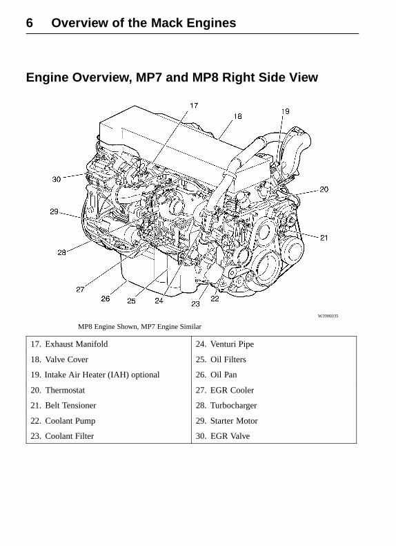
Engine Overview, MP7 and MP8 Right Side View
W2006035
MP8 Engine Shown, MP7 Engine Similar
17. Exhaust Manifold 24. Venturi Pipe
18. Valve Cover 25. Oil Filters
19. Intake Air Heater (IAH) optional 26. Oil Pan
20. Thermostat 27. EGR Cooler
21. Belt Tensioner 28. Turbocharger
22. Coolant Pump 29. Starter Motor
23. Coolant Filter 30. EGR Valve

Overview of the Mack Engines 7
Engine Overview, MP10 Left Side View
W2006037
1. Breather Tube 9. Fuel/Water Separator
2. Intake Manifold 10. Fuel Filter
3. Air Compressor 11. Hand-Priming Pump
4. Power Steering Pump 12. Alternator
5. Fuel Pump 13. AC Compressor
6. Crankcase Ventilator 14. Alternator/AC Compressor Belt
7. Engine Control Module (ECM) 15. Fan/Coolant Pump Belt
8. Fuel Filter 16. Venturi Pipe
17. EGR Mixing Chamber

8 Overview of the Mack Engines
Engine Overview,MP10 Right Side View
W2006036
18. Exhaust Manifold 24. Coolant Filter
19. Valve Cover 25. Oil Filters
20. Intake Air Heater (IAH) 26. EGR Cooler
21. Thermostat 27. Oil Pan
22. Belt Tensioner 28. Starter Motor
23. Coolant Pump 29. Turbocharger
30. EGR Valve

Mack, EPA2010 Emissions Solution 9
Exhaust Aftertreatment SystemCHU, CXU, GU and TD Standard System View
W2029933
1. Selective Catalytic Reduction (SCR)Catalyst
2. Aftertreatment DEF Dosing Unit
3. Aftertreatment Diesel Particulate Filter(DPF)
4.Aftertreatment DEF Tank

10 Mack, EPA2010 Emissions Solution
LEU and MRU Standard System View
W2031562
1. Selective Catalytic Reduction (SCR)Catalyst
2. Aftertreatment DEF Dosing Unit
3. Aftertreatment Diesel Particulate Filter(DPF)
4.Aftertreatment DEF Tank

Mack, EPA2010 Emissions Solution 11
Safety InformationThe exhaust aftertreatment system utilizestechnology that oxidizes trapped particlesand unburned hydrocarbons therebyreducing emissions. This oxidation occursduring the regeneration process. Whileregeneration is occurring, very high exhaustgas temperatures will occur. In somevehicles, regeneration can occur when thevehicle is stationary.
DANGER
Exhaust gases and components can beat extremely high temperatures duringregeneration. When parking the vehicle,keep away from any flammable materials,vapors, or structures.
DANGER
The temperature of the exhaust systemcomponents during the regenerationprocess can exceed 350 degrees C (660F). The exhaust gas leaving the systemcan reach 505 degrees C (930 F). Variousfactors (including ambient temperatureand duration of the regeneration process)determine when these components willreturn to normal operating temperatureafter regeneration has completed.Be extremely careful around thesehot components. Contact with thesecomponents can result in serious personalinjury.

12 Mack, EPA2010 Emissions Solution
Exhaust Aftertreatment System Components andOperationSelective Catalytic Reduction (SCR)Selective Catalytic Reduction (SCR)is an emissions-reduction technologywith the ability to deliver near-zeroemissions of nitrogen oxides (NOx), asmog-causing pollutant and greenhousegas. SCR’s performance has been provedin millions of miles of real-world truckoperations in other countries, as well as inlong-term field tests in the U.S.
SCR reduces NOx emissions tovery low levels, while at the same timedelivering excellent fuel economy andreliability. The system doesn’t change thedesign or operation of the basic engine.Rather, SCR is an aftertreatment systemwhich converts NOx in the exhaust streaminto harmless gases. Modern diesels already
use exhaust aftertreatment systems, calleddiesel particulate filters, to control emissionsof another pollutant, soot (also knownas particulate matter or PM).
SCR works by injecting DieselExhaust Fluid (DEF) into the exhaust. DEFis a safe, simple solution of water and urea.DEF works with the heat of the exhaust anda catalyst to convert NOx into nitrogen andwater vapor - two harmless and naturalcomponents of the air we breathe. The endresult is cleaner air, excellent fuel efficiencyand a reliable emissions control system fortoday’s modern diesel engine.
W2031651
1. Diesel Engine
2. Aftertreatment DEF Tank
3. Aftertreatment DEF Pump
4. Aftertreatment DEF Dosing Unit
5. Aftertreatment Diesel Particulate Filter (DPF)
6. Selective Catalytic Reduction (SCR) Catalyst
7. Aftertreatment DEF Tank Gauge

Mack, EPA2010 Emissions Solution 13
There are 2 different shapes for the SCRcatalysts, they are vertical and horizontal.The horizontal SCR catalyst comes in 2different sizes, a full size or a compact. Thevertical SCR catalyst comes in 1 size, withtwo different intakes, it will either have abottom intake or a side intake.The Mack SCR system is simple andeffective, with few components. It consistsof a Aftertreatment DEF tank positionednear the standard diesel tank, plus aAftertreatment DEF pump, AftertreatmentDEF Dosing unit and SCR catalyst. Theadvantage of using DEF is that it enablesthe engine to use less EGR -- and higheroxygen levels -- for better combustion,while meeting the EPA near-zero NOxemissions requirement of 0.2 g/hp-hr NOx.By using DEF, we avoid the disadvantagesof increasing EGR to massive levels. Thisresults in better fuel economy from yourMack engine.
1 Diesel engine optimized for highperformance, low particle emissionsand low fuel consumption.
2 Aftertreatment DEF tank3 The Aftertreatment Control Module
(ACM) continuously monitors andadjusts the Aftertreatment DEF pumppressure in response to current engineload conditions.
4 DEF is injected into the exhaust gasesin between the Aftertreatment DPF (5)and the SCR catalyst (6).
5 Aftertreatment Diesel Particulate Filter(DPF).
6 In the SCR catalyst, nitrogen oxidesare transformed into harmless nitrogengas and water.
7 The system notifies the driver when it istime to refill tank with DEF.
CAUTION
Do not put diesel fuel in the AftertreatmentDEF tank. Diesel fuel, if sprayed intothe hot exhaust along with the DEF,could ignite explosively causing a fireresulting in personal injury or damage tothe exhaust system.

14 Mack, EPA2010 Emissions Solution
Diesel Exhaust Fluid (DEF)Diesel Exhaust Fluid (DEF) is a reactantthat’s key to the SCR process. It’s a nontoxic,aqueous solution of 32.5% urea and 67.5%water. Urea is a compound of nitrogen thatturns to ammonia when heated. It is usedin a variety of industries, perhaps most
commonly as a fertilizer in agriculture. Thefluid is not inflammable, nor is it dangerouswhen handled normally. However, it ishighly corrosive to metal, particularly copperand aluminium. Read the separate sectionconcerning the handling of DEF solution.
Diesel Exhaust Fluid (DEF) HandlingWhen handling DEF solution, it is importantthat electrical connectors to be connected orwell encapsulated. Otherwise there is a riskthat the DEF will cause oxidation that cannotbe removed. Water or compressed air do nothelp, since DEF quickly oxidizes metal. If aconnector comes into contact with the DEFsolution it must be replaced immediatelyto prevent the DEF solution from creepingfurther into the copper wiring, which takesplace at a speed of about 60 cm (2.4 in) perhour.
CAUTION
When detaching hoses and components,do not spill DEF on disconnectedconnectors. If DEF is spilled on aconnector, the connector must be replacedimmediately
Things to know about spilled Diesel Exhaust Fluid (DEF)
If urea solution comes into contact with the skin ? rinse with plenty of water and removecontaminated clothing.
If urea solution comes into contact with the eyes ? rinse for several minutes and call formedical help if necessary.
If inhaled ? Breathe fresh air and call for medical help if necessary.
Do not allow the DEF solution to come into contact with other chemicals.
The DEF solution is not flammable. If the DEF solution is exposed to high temperatures, itbreaks down into ammonia and carbon dioxide.
The DEF solution is highly corrosive to certain metals, including copper and aluminium.
If the DEF solution is spilled onto the vehicle, wipe off the excess and rinse with water.Spilled DEF solution can form concentrated white crystals on the vehicle. Rinse off thesecrystals with water.
Note: Do not flush DEF spillages into thenormal drain system. WARNING
DEF spilt onto hot components willquickly vaporize. Turn your face away!

Mack, EPA2010 Emissions Solution 15
Diesel Exhaust Fluid (DEF) ConsumptionDEF consumption is related to fuelconsumption. A highway truck may travel225-300 miles or more on one gallon of DEF.If a driver runs out of DEF a gauge muchlike a fuel gauge will indicate the level ofDEF in the tank. A DEF low-level warning
will activate when DEF is low. If a driverruns out of DEF completely, vehicle powerwill be reduced to derate mode. When theDEF tank is refilled, the engine will resumenormal power.
Diesel Exhaust Fluid (DEF) AvailabilityDEF will be available in 2.5-galloncontainers, 55-gallon drums, 275 gallonIBC and in bulk storage for fleet locations,truck stops and dealerships. DEF willbe everywhere drivers are. All major
truck stops, dealers and distributors willcarry DEF. For more information on DEFand availability please visit the websitewww.truckscr.com .
Aftertreatment Control Module (ACM)
W2029917
The ACM controls the followingcomponents in the exhaust aftertreatmentsystem:
• Aftertreatment DEF Dosing Unit
• Aftertreatment DEF Tank Heater Valve
• Aftertreatment DEF Line Heaters
• Aftertreatment DEF Pump
• Aftertreatment DEF Return Valve
• Aftertreatment DEF Tank Level Sensor
The ACM also monitors the followingvalues in the exhaust aftertreatmentsystem:
• Aftertreatment DEF Dosing AbsolutePressure
• Aftertreatment DEF Tank Temperature
• Aftertreatment DEF Tank Level
• Aftertreatment DPF Inlet/OutletTemperature
• Aftertreatment DPF DifferentialPressure
• NOX Sensors
The ACM is a stand alone module.Depending on your configuration it may bemounted as part of the DEF tank (as shownabove) or on a bracket near the DEF tank.

16 Mack, EPA2010 Emissions Solution
Aftertreatment Diesel Particulate Filter (DPF)
CAUTION
Use of diesel fuel other than ULSD andengine oils other than EO-O PremiumPlus (or VDS-4), will adversely affectperformance, efficiency and durability ofthe Aftertreatment DPF system and theengine, to the point where the engine maynot run at all. Manufacturer’s warrantiescan also be rendered void due to usage ofimproper fuel. Unapproved fuel additives(including engine oil) are NOT permitted.Blends of No. 1D and No. 2D grades ofULSD are recommended and allowablefor cold weather operations.
The exhaust aftertreatment system virtuallyeliminates exhaust smoke. Exhaust vapor(water condensation) may be visible during acold start. If exhaust smoke is visible duringengine operation, this indicates a problem
with the exhaust aftertreatment system. Takethe vehicle to an authorized Mack Truckdealer immediately.
Vehicles equipped with a 2010 emissioncompliant engine have an exhaustaftertreatment system which includes aSelective Catalytic Reduction (SCR) systemand a Catalyzed Aftertreatment DieselParticulate Filter (DPF). The AftertreatmentDPF takes the place of the standard muffler,and it reduces soot and particulate emissionsinto the atmosphere. Soot and otherparticulate matter are collected by a filterwhere it is eventually oxidized using aregeneration process. Vehicles equippedwith a Aftertreatment DPF require theuse of EO-O Premium Plus (or VDS-4)specification high performance diesel engineoil and Ultra Low Sulfur Diesel (ULSD) fuel.
W2030326

Mack, EPA2010 Emissions Solution 17
Exhaust Aftertreatment System Operation
Aftertreatment DPF Regeneration
DPF Smart Switch – This is a three-position switch where the middle position isneutral.
C0029148
DPF Smart Switch
1. Upper Position – RegenerationPosition
3. Down Position – Inhibit Position (ifequipped)
2. Middle Position – Neutral Position

18 Mack, EPA2010 Emissions Solution
CAUTION
During the Aftertreatment DPF Regeneration Required , the exhaust gas temperature willbe elevated. DO NOT park the vehicle with the exhaust outlet near flammable objectssuch as trees, awnings, etc. that could be damaged by elevated exhaust gas temperatures.
CAUTION
If the vehicle is in a location that may be hazardous when Aftertreatment DPFRegeneration Required begins (i.e., in close proximity to flammable materials orgases, inside tunnels, parked under flammable objects, etc.), the Aftertreatment DPFRegeneration Required should be stopped (if equipped). If Aftertreatment DPFRegeneration Required is stopped by the vehicle operator, it must be initiated at a latertime when the vehicle is in a safer location. Aftertreatment DPF Regeneration Requiredthat are stopped and never restarted at a later time, however, will require that the vehiclebe taken to an authorized Mack Truck dealer to have the Aftertreatment Regenerationmanually started with special service tools.
Note: If Aftertreatment DPF Regeneration Required occurs during vehicle operation,idle speed may increase when the vehicle is stopped at a traffic light to maintain properAftertreatment DPF Regeneration Required conditions.
There are two types of Aftertreatment DPFRegeneration Required: Moving and Parked.Moving Aftertreatment DPF RegenerationRequired only occurs when the vehicle ismoving at uninterrupted highway speed.
Parked Aftertreatment DPF RegenerationRequired is manually initiated when thevehicle is stationary. This is the standardconfiguration. Other configurations areavailable.

Mack, EPA2010 Emissions Solution 19
Moving Regeneration
"Moving" regeneration occurs while the vehicle is being driven and can be automatic(no operator input needed to start regeneration) or manual (operator input neededto start regeneration). The operator is notified that a regeneration is needed whenthe icons on the DPF Smart switch illuminate (refer to Figure listed below).
Note: The vehicle operator should try to maintain vehicle speed during theregeneration process. If the vehicle must be stopped (at a traffic light for example),allow the vehicle to idle and do not apply the park brake. Applying the park brakewill disrupt and end a regeneration that started while the vehicle was being driven.
Please refer to the instructions below on how to use the DPF Smart switch during aregeneration that occurs while the vehicle is being driven.
Moving (Automatic) Regeneration
1 When the icons on the DPF Smart switch light up, maintain vehicle speed ifpossible.
2 During regeneration, the icons on the switch will shut off.
3 Regeneration will take between 20 and 30 minutes to complete.
4 To stop regeneration, press the switch down to the inhibit position (if equipped).When the bottom of the switch is illuminated, regeneration is stopped. Theswitch will remain locked in this position and the light will stay illuminated. Thedriver has the option of stopping a regeneration if the vehicle is in an areawhere elevated exhaust temperatures will pose a hazard (i.e., tunnel, undertrees, in an area where there is flammable material, etc.).

20 Mack, EPA2010 Emissions Solution
Moving (Manual) Regeneration (If Available)
1 When the icons on the DPF Smart switch light up, maintain vehicle speed andpress and hold the top part of the switch momentarily.
2 During regeneration, the icons on the switch will shut off.
3 Regeneration will take between 20 and 30 minutes to complete.
4 To stop regeneration, press the switch down to the inhibit position (if equipped).When the bottom of the switch is illuminated, regeneration is stopped. Theswitch will remain locked in this position and the light will stay illuminated. Thedriver has the option of stopping a regeneration if the vehicle is in an areawhere elevated exhaust temperatures will pose a hazard (i.e., tunnel, undertrees, in an area where there is flammable material, etc.).
Depending on the vehicle’s set up, it may be possible to perform a parkedregeneration if necessary.

Mack, EPA2010 Emissions Solution 21
Parked Regeneration
Parked regeneration allows the operator to start and/or stop the regenerationmanually when the vehicle is parked and the engine is idling. The operator isnotified that a regeneration is needed when the icons on the DPF Smart switchilluminate. The operator should perform the regeneration as soon as possible.
Please refer to the instructions below on how to use the DPF Smart switch forparked regenerations.
1. Move the vehicle to a safe location, apply the park brake and allow the engine toidle.
WARNING
When a regeneration is in process, the temperature of the exhaust willbe elevated. DO NOT park the vehicle with the exhaust outlet under lowhanging overhead flammable objects such as trees, awnings, etc., thatcould be damaged by elevated exhaust temperatures. DO NOT attempt toregenerate inside a garage or enclosed area if the tail pipe is attached toan exhaust ventilation system as the hose material may not be rated forthe high temperature.
2. Press and hold the top part of the DPF Smart switch momentarily to initiatethe regeneration.
3. During regeneration, the icons on the switch will shut off. The HEST indicator onthe instrument cluster will light up to notify of high exhaust temperatures.
4. For aftertreatment DPF filter systems which are not Spark Assisted, the enginespeed may ramp as high as 1,100 rpm. For Aftertreatment DPF filter spark assistedsystems, the engine will continue to idle during the regeneration.
5. Regeneration will take between 20 and 30 minutes to complete.
6. After regeneration has completed and the exhaust temperature has returned tonormal, the HEST indicator will shut off.
7. To stop regeneration, press the switch down to the inhibit position (if equipped).When the bottom of the switch is illuminated, regeneration is stopped. The switchwill remain locked in this position and the light will stay illuminated. The driver hasthe option of stopping a regeneration if the vehicle is in an area where elevatedexhaust temperatures will pose a hazard (i.e., tunnel, under trees, in an area wherethere is flammable material, etc.).

22 Mack, EPA2010 Emissions Solution
CAUTION
Failure to perform a regeneration in a timely manner after notification may resultin engine derate, a clogged DPF, damage to the DPF and engine shutdown.
DANGER
During the regeneration process (with either system), the temperature ofthe exhaust gases will be elevated. DO NOT park or stop for an extendedperiod under low hanging overhead flammable objects such as trees,awnings, structures, etc., that could be damaged by elevated exhausttemperatures. Further, if the vehicle is being operated in an area whereflammable vapors exist, the regeneration process must be interrupted.Failure to heed these cautions may result in fire or explosion causingserious personal injury or death.
When regeneration is needed, an icon at the top of the DPF Smart switch willilluminate to notify the vehicle operator. The DPF Smart switch allows the vehicleoperator to either stop or start regeneration. (Certain conditions must be met,however, before regeneration can be manually started.)
Note: If the vehicle is in a location that may be hazardous when an activeregeneration begins (i.e., in close proximity to flammable materials or gases),the regeneration should be stopped by pushing the DPF switch to the "StopRegeneration" position.If an active regeneration is stopped by the vehicle operator, it should be initiated at alater time when the vehicle is in a safe location. However, if an active regenerationis stopped too many times, the vehicle must be taken to a MACK service facility.The service facility will use a service tool to manually initiate the regeneration.
WARNING
The temperature of the exhaust system components during theregeneration process can exceed 500 �C (1000�F). Various factors (includingambient temperature and duration of the regeneration process) determinewhen these components will return to normal operating temperatureafter regeneration has completed. Be extremely careful around thesehot components. Contact with these components can result in seriouspersonal injury.

Mack, EPA2010 Emissions Solution 23
CAUTION
When the inhibit position is pressed, the switch will remain in a locked position. Itis important, therefore, to immediately set the switch back to the neutral positionwhen safe to do so. Failure to set the switch back to the neutral position mayresult in an engine derate, clogged diesel particulate filter or damage to the filter.
DPF INHIBIT ROAD SPEED LIMITING (RSL)
The DPF Smart Switch can be locked into the DOWN (or Inhibit Regen) position bythe driver (if equipped). If the DPF Smart Switch remains in the locked position, thefollowing vehicle speed limiting will occur:
1 Vehicle Moving. If vehicle is moving with the DPF Smart Switch in the locked(DOWN) position, the vehicle speed will decrease down to 16 kph (10 mph)below the current speed until the driver releases the switch back to the neutral(MIDDLE) position.
2 Vehicle Stationary and then Moving. If the vehicle is stationary with the DPFSmart Switch in the locked (DOWN) position and the driver then begins to movethe truck, the vehicle speed will be limited to 16 kph (10 mph) until the driverreleases the switch back to the neutral (MIDDLE) position.

24 Mack, EPA2010 Emissions Solution
Refer to the Exhaust Aftertreatment SystemInformation sun visor label for additionalAftertreatment DPF information.
W8029446

Mack, EPA2010 Emissions Solution 25
Driver Warnings and On Board Diagnostics (OBD)
On Board Diagnostics (OBD)Beginning with your EPA2010 compliantVehicle, On Board Diagnostics (OBD)is introduced. This is very similarto the On Board Diagnostics (OBD)system that has been required onpassenger cars for many years.
On Board Diagnostics (OBD)is a system that monitors the functions ofemissions related components and alert the
vehicle operator to any detected need for anemission related repair. When the systemsdetects a needed repair to an emissionsrelated component it activates the Mal-function Indicator Lamp (MIL).
The list of emissions relatedcomponents can be found in the Warrantyand Maintenance section of this manual
Instrument ClusterThe aftertreatment icons are located in theinstrument cluster per the following images.
CHU, CXU, GU and TD Instrument Cluster
W3031621
1. MalfunctionIndicator Lamp(MIL)
2. CHECK Lamp 3. AftertreatmentDEF Low Lamp
4. High ExhaustTemperature(HEST) Lamp
6. AftertreatmentDEF Tank Gauge

26 Mack, EPA2010 Emissions Solution
LEU and MRU Instrument Cluster
W3031622
A Left Side Indicator Set B Right Side Indicator Set
1. MalfunctionIndicator Lamp(MIL)
2. CHECK Lamp 3. AftertreatmentDEF Low Lamp
4. High ExhaustTemperature(HEST) Lamp
5. AftertreatmentDPF RegenerationRequired Lamp
6. AftertreatmentDEF Tank Gauge

Mack, EPA2010 Emissions Solution 27
Instrument Cluster IconsAftertreatment icons are displayed on theinstrument cluster. There are 3 aftertreatmenticons:
• Aftertreatment DPF RegenerationRequired
• High Exhaust System Temperature(HEST)
• Aftertreatment DEF Tank Low LevelIndicator
The Aftertreatment DPF RegenerationRequired icon illuminates when the DieselParticulate Filter is becoming full andregeneration is needed. The icon flasheswhen the filter is full or overfull.
W3007445
Aftertreatment DPF RegenerationRequired Icon
The High Exhaust System Temperature iconilluminates when a parked Aftertreatment
DPF Regeneration Required is initiated. Italso indicates high exhaust gas temperatureduring an at-speed regeneration. Whenthe HEST icon is illuminated, do not parkor operate the vehicle near people, or anyflammable materials, vapors, or structures.
W3007444
High Exhaust System Temperature(HEST) Icon
W2029416
Aftertreatment DEF Tank LowLevel Indicator (DEF)
The Aftertreatment DEF Tank Low LevelIndicator icon illuminates when the fluidlevel is low. It also Flashes when the levelbecomes critically low.
Malfunction Indicator Lamp (MIL)
W3031200
MIL Lamp
• MIL indicates government RegulationOn Board Diagnostics (OBD) faults
• Lamp may remain active after repairuntil system operation confirms repair

28 Mack, EPA2010 Emissions Solution
Aftertreatment DEF Tank Level - Driver Warning & InducementAftertreatment DEF tanks are sized tohave no less than 2 times the diesel fueltank mileage or hour range
The vehicle instrument cluster has aAftertreatment DEF Tank Level Gage
Triggers AftertreatmentDEF Tank LowLevel Indicator
Amber WarningLamp
Inducement
>12% AftertreatmentDEF Tank LevelGauge (>16% DEFRemaining)
None None None
<=12%AftertreatmentDEF Tank LevelGauge (~16% DEFRemaining)
W2029416
None None
0% AftertreatmentDEF Tank LevelGauge (~4% DEFRemaining)
W2029415
None 25% torquereduction
0%AftertreatmentDEF Tank GaugeInsufficient DEFPump PressureDiesel FuelRefueling >15% W2029415
None 5 mph Road SpeedLimit (RSL) 1
1 Vehicle has to be stationary before 5 mph RSL becomes Active
Exit conditions for DEF Quality "5 mph road speed limit" Inducement:
Next 10 Engine Starts:Return to 25% torque reduction until proper DEF quality evaluation.If poor DEF quality is detected during the next monitoring cycle then and 5 mph resumedafter vehicle stationary for 20 minutes. After 10 engine starts have been exhausted then aService Tool is required to exit the 5 mph RSL.
With Scan Tool DTC Clearing: Invoke 25% torque reduction until proper DEF qualityevaluation. If poor DEF Quality is detected during the next monitoring cycle then 5 mphresumed after vehicle stationary for 20 minutes.

Mack, EPA2010 Emissions Solution 29
Aftertreatment DEF Quality - Driver Warning & Inducement
Triggers AftertreatmentDEF Tank LowLevel Indicator
Amber WarningLamp
Inducement
Good DEF Quality None None None
Poor DEF QualityDTC Initial Detected1 2 3
None
W3031623
None
Poor DEF QualityDTC Initial Detected+ 10 hours
None
W3031623
25% torque reduction
Poor DEF QualityDTC Initial Detected+ 20 hours DieselFuel Refueling>15%
None
W3031623
5 mph Road SpeedLimit (RSL) 4
Temporary Exit from5 mph Inducement
None
W3031623
25% torque reduction
1 Based on an NOx sensor evaluation of measured versus predicted SCR NOx conversion2 Poor DEF Quality defined as DEF diluted with water in 50/50% proportions3 Confirmation occurs during the initial OBD drive cycle4 Vehicle has to be stationary before 5 mph RSL becomes Active
Exit conditions for DEF Quality "5 mph road speed limit" Inducement:
Next 10 Engine Starts:Return to 25% torque reduction until proper DEF quality evaluation.If poor DEF quality is detected during the next monitoring cycle then and 5 mph resumedafter vehicle stationary for 20 minutes. After 10 engine starts have been exhausted then aService Tool is required to exit the 5 mph RSL.
With Scan Tool DTC Clearing: Invoke 25% torque reduction until proper DEF qualityevaluation. If poor DEF Quality is detected during the next monitoring cycle then 5 mphresumed after vehicle stationary for 20 minutes.

30 Mack, EPA2010 Emissions Solution
Misfilling Diesel or Aftertreatment DEF TanksAlthough diesel fuel and Aftertreatment DEFcaps are clearly labeled and filler necks andnozzles are different accidents can happen.
Contamination of fluids by- misfiling ofdiesel or DEF in the wrong tank may resultin vehicle malfunction.
Results of misfilling DEF in Diesel Tank
• Engine may run poorly or not at all
• Injectors may be damaged
• Exhaust system corrosion mayoccur between turbocharger andAftertreatment DPF
• On Board Diagnostic (OBD) DiagnosticTrouble Codes (DTC)
• Costly repairs
Results of misfilling Diesel inAftertreatment DEF Tank
• Aftertreatment SCR system may bedamaged by Diesel
• SCR Catalyst may be damaged bydiesel (chemical damage)
• Emissions may be non-compliant
• On Board Diagnostic (OBD)DiagnosticTrouble Codes (DTC)
• Costly repairs

Mack, EPA2010 Emissions Solution 31
SCR Tampering - Driver Warning & Inducement
1. Disconnected Aftertreatment DEF tanklevel sensor
4. Disconnected Aftertreatment DEF pump
2. Blocked Aftertreatment DEF line ordosing unit
5. Disconnected SCR wiring harness
3. Disconnected Aftertreatment DEF dosingunit
6. Disconnected NOx Sensor
Triggers AftertreatmentDEF Tank LowLevel Indicator
Warning Lamp Inducement
No Tampering None None None
Tampering DTCPending1
None
W3031623
None
Tampering DTCConfirmed2
None
W3031623
None
Tampering DTCInitial Detected + 10hour
None
W3031623
25% torquereduction
Tampering DTCInitial Detected + 40hours Diesel FuelRefueling >15%
None
W3031623
5 mph road speedlimit 3
1 Tampering DTC Pending does not apply to DEF Tank Level Sensor2 Confirmation occurs at the next OBD drive cycle3 Vehicle has to be stationary before 5 mph RSL becomes Active
32 Mack, EPA2010 Emissions Solution
Exit conditions for DEF Quality "5 mph road speed limit" Inducement:
Next 10 Engine Starts:Return to 25% torque reduction until proper DEF quality evaluation.If poor DEF quality is detected during the next monitoring cycle then and 5 mph resumedafter vehicle stationary for 20 minutes. After 10 engine starts have been exhausted then aService Tool is required to exit the 5 mph RSL.
With Scan Tool DTC Clearing: Invoke 25% torque reduction until proper DEF qualityevaluation. If poor DEF Quality is detected during the next monitoring cycle then 5 mphresumed after vehicle stationary for 20 minutes.
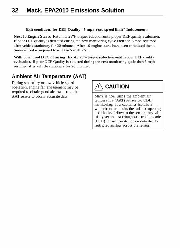
Ambient Air Temperature (AAT)During stationary or low vehicle speedoperation, engine fan engagement may berequired to obtain good airflow across theAAT sensor to obtain accurate data.
CAUTION
Mack is now using the ambient airtemperature (AAT) sensor for OBDmonitoring. If a customer installs awinterfront or blocks the radiator openingand blocks airflow to the sensor, they willlikely set an OBD diagnostic trouble code(DTC) for inaccurate sensor data due torestricted airflow across the sensor.

Mack, EPA2010 Emissions Solution 33
Warranty and MaintenanceExhaust Aftertreatment System MaintenanceThe vehicle must be taken to an authorizedMack Truck dealer to remove the ash fromthe Aftertreatment Diesel Particulate Filterand clean the Aftertreatment Doser.
Emissions MaintenanceEmissions Maintenance Interval - EPA/ CARB defines this as the adjustment,cleaning, repair, or replacement shall berecommended at intervals no less thandescribed below.
Injector tips (cleaning only), crankcaseventilation valve, EGR filters and coolers:
Heavy Heavy Duty:
Miles: 50,000
Hours: 1500
Injectors, Turbocharger , ECM, sensors,actuators, EGR components (except filter andcoolers), Aftertreatment DPF plus relatedcomponents, this includes ash cleaning
Heavy Heavy Duty:
Miles: 150,000
Hours: 4500
1. If owner’s manual recommendsAfertreatment DPF replacement withinuseful life, the manufacturer must pay forthe replacement; however, a random failurewithin the useful life is covered only per theabove warranty provisions.
2. First maintenance interval in life of theengine is allowed at 100,000 miles, 3000hours.
Engine Maintenance Intervals
Component Operation Interval
Fuel Filter Change
Every oil change. Under certainconditions (for example, irregular fuelquality), the fuel/water separator filtersmay require more frequent replacement.
Water Separator Filter Change
Every oil change. Under certainconditions (for example, irregular fuelquality), the fuel/water separator filtersmay require more frequent replacement.
Air Cleaner Change Control lamp indication or 24 months,whichever comes first
Coolant (Standard) Change500 000 km (300,000 miles ) or 24months, whichever comes first
Coolant (ELC) Change1 000 000 km (600,000 miles) or 48months, whichever comes first

34 Mack, EPA2010 Emissions Solution
Component Operation Interval
Coolant Filter (Standard) Change 80 000 km (50,000 miles) or 6 months,whichever comes first
Coolant Filter (ELC) Change240 000 km (150,000 miles) or 12months, whichever comes first
Valves/Injectors, MP7 andMP8 Initial Adjust
200 000 km (125,000 miles) or 12months, whichever comes first
Injectors, MP7 and MP8 AdjustEvery 400 000 km (250,000 miles) or24 months, whichever comes first
Valves/Injectors, MP10 Initial Adjust100 000 km (60,000 miles) or 6 months,whichever comes first
Injectors, MP10 AdjustEvery 200 000 km (125,000 miles) or12 months, whichever comes first
Main drive and accessorydrive Belts, Highway UsageMP7 and MP8
Change500 000 km (300,000 miles) or 36months, whichever comes first
Main drive and accessorydrive Belts, VocationalUsage MP7 and MP8
Change240 000 km (150,000 miles) or12months, whichever comes first
Main drive and accessorydrive Belts, VocationalUsage MP10
Change500 000 km (300,000 miles) or 36months, whichever comes first
Aftertreatment DPF Filter Exchange400 000 km (250,000 miles) or 4,500hours, whichever occurs first
Aftertreatment DPF AshCleaning
Clean400 000 km (250,000 miles) or 4,500hours, whichever occurs first
Aftertreatment Doser Clean240 000 km (150,000 miles) or 4,500hours, whichever occurs first
Aftertreatment DieselExhaust Fluid (DEF) Filter
Change354 000km (220,000 miles) 7000 hoursor 3 years, whichever comes first

Mack, EPA2010 Emissions Solution 35
Oil Change IntervalsThe length of time an engine can operatebefore an oil change depends on thequality oil used, the type of fuel used,fuel consumption, engine oil consumption,vehicle application, level of dust in the air,and fuel consumption. The change intervalsgiven in this manual are maximum intervals.If the vehicle is operating in heavy-duty
or severe duty operation, dusty or off-roadconditions, etc., reduce the intervals for morefrequent oil changes.
Note: Use the information in the table belowto determine the operating condition andusage applicable to your vehicle.
Engine Operating Condition Medium Heavy Severe
Total Fuel Consumption (mpg) more than 6 more than 4.7 more than 3.7
Total Fuel Consumption (L/100 km) less than 39 less than 50 less than 64
MP7 and MP8 Engine Oil and FilterChange Interval, km (miles) — 36L (38quart) oil capacity
MP10 Engine Oil and Filter ChangeInterval, km (miles) — 42L (44 quart) oilcapacity
56 000(35,000)
40 000(25,000)
24 000(15,000)
MP10 Engine Oil and Filter ChangeInterval, km (miles) — 52L (55 quart) oilcapacity
80 000(50,000)
56 000(35,000)
40 000(25,000)
Note: If idle time is greater than 25%, use the next lower drain interval.
For additional information about oil changeintervals, see your Mack Truck dealer. Also,refer to Bulletin 175-60, Oil and Filters,Mack Components.
For a complete list of approved oils, see yourMack Truck dealer. Also, refer to Bulletin175-61, Approved Oils, Mack Components.

36 Mack, EPA2010 Emissions Solution
Emissions Control System Warranty
The following engine components are covered by the supplemental emissions control systemwarranty policy as required by the Federal emissions regulations.
1 Turbocharger Assembly
• VGT Actuator2 Charge Air Cooler
• CAC Pipes (Air inlet to/fromCAC)
• CAC Hoses3 Injectors4 Engine and Vehicle Wire harness
( connected to OBD Signal, ECM,VECU, Instrument Cluster andTransmission Control Module withVehicle Speed/Output Shaft Sensor)
5 EGR Mixer6 EGR Cooler7 EGR Valve and EGR Control Valve8 EGR Pipes - Exhaust Manifold to EGR
cooler9 EGR Pipes - EGR cooler to inlet
manifold10 Crankcase Breather11 Crankcase Separator12 Crankcase Tubing and Hoses before
Separator13 Aftertreatment Wiring Harness14 After treatment Control Module (ACM)15 Aftertreatment Diesel Particulate Filter
(DPF) Assembly
A. Aftertreatment DPF Assemblywith Diesel Oxidation Catalyst(DOC)
• Aftertreatment Doser• Diffuser Pipe (Aftertreatment
Doser mounting)• Fuel lines to Aftertreatment
Doser• Aftertreatment Fuel Shutoff
Valve
• Aftertreatment Fuel PressureSensor
• Discharge RecirculationValve (DRV) (Heat Mode)
• Discharge RecirculationValve (DRV) Solenoid
• Engine EGT Sensor• Aftertreatment DPF Intake
Temperature Sensor• Aftertreatment DPF Outlet
Temperature Sensor• Aftertreatment DPF
Differential Pressure Sensor
B. Aftertreatment DPF SparkAssisted Assembly
• Aftertreatment DPFCombustion Air Valve
• Aftertreatment DPFAtomization Module
• Aftertreatment DPF IgnitionCoil
• Aftertreatment DPF FuelControl Valve
• Aftertreatment DPF IgnitionElectrode
• Nozzle• Engine Exhaust Gas
Temperature (EGT) Sensor• Aftertreatment DPF Intake
Temperature Sensor• Aftertreatment DPF Outlet
Temperature Sensor• Aftertreatment DPF Flame
Temperature Sensor• Aftertreatment DPF
Differential Pressure Sensor

Mack, EPA2010 Emissions Solution 37
16 Sensors:
• Crankshaft Position (CKP)• Camshaft Position (CMP)• Engine Coolant Temperature
(ECT)• Intake Manifold Air Temperature• Intake Manifold Pressure (IMP)• EGR Temperature• EGR Differential Pressure• Engine Coolant Level (ECL)• Vehicle Speed (VSS)• Ambient Air Temperature (AAT)
17 SCR
• SCR Catalyst• Aftertreatment DEF Pump
• Aftertreatment DEF DosingAbsolute Pressure Sensor
• Aftertreatment DEF ReturnValve
• Aftertreatment DEF Dosing Unit
• Aftertreatment DEF Tank and lines• Aftertreatment DEF Tank Heater
Valve• Aftertreatment DEF Tank
Temperature Sensor• Aftertreatment DEF Level Sensor• Aftertreatment Outlet NOx• Aftertreatment Intake NOx• Aftertreatment DEF Line Heaters
21. Vehicle Electronic Control Unit(ECU)
22. Instrument Cluster (with ECU,MIL, Real Time Clock, AftertreatmentDEF Tank Gauge and, DEF Tank LowLevel Indicator)
23. Exhaust gas piping (fromturbocharger to aftertreatment)
24. Transmission Control Module(TCM) (with Vehicle Speed / OutputShaft Sensor

Mack Trucks, Inc.P.O. Box 26259 Greensboro, NC 27402-6115
Mack Trucks Canada, Ltd. 2100 Derry Road West, Suite 410, Mississauga, Ontario L5N 0B3
http://www.macktrucks.com
PV776-21414253 (USA) 07.2009 © Mack Trucks, Inc. , 2009