Embed Size (px)
Citation preview
DRIVER CONTROLS
C
D
E
SECTION DEFA
B
DEFOGGER
F
G
H
I
J
K
M
EF
N
O
P
CONTENTS
D
BASIC INSPECTION .................................... 3
DIAGNOSIS AND REPAIR WORKFLOW .......... 3Work Flow .................................................................3
FUNCTION DIAGNOSIS ............................... 6
REAR WINDOW DEFOGGER SYSTEM ............. 6System Diagram ........................................................6System Description ...................................................6Component Parts Location ........................................7Component Description .............................................7
DIAGNOSIS SYSTEM (BCM) ............................. 9
COMMON ITEM ...........................................................9COMMON ITEM : CONSULT-III Function (BCM - COMMON ITEM) .......................................................9
REAR WINDOW DEFOGGER .....................................9REAR WINDOW DEFOGGER : CONSULT-III Function (BCM - REAR DEFOGGER) ......................9
CAN COMMUNICATION ....................................10System Description .................................................10
COMPONENT DIAGNOSIS .........................11
REAR WINDOW DEFOGGER SWITCH ............11Description ..............................................................11Component Function Check ....................................11Diagnosis Procedure ...............................................11
REAR WINDOW DEFOGGER RELAY ..............12Description ..............................................................12Component Function Check ....................................12Diagnosis Procedure ...............................................12Component Inspection ............................................13
REAR WINDOW DEFOGGER POWER SUP-PLY AND GROUND CIRCUIT ............................14
Description ..............................................................14Component Function Check ....................................14
Diagnosis Procedure ...............................................14Component Inspection .............................................15
DRIVER SIDE DOOR MIRROR DEFOGGER ...16Description ...............................................................16Component Function Check ....................................16Diagnosis Procedure ...............................................16Component Inspection .............................................17
PASSENGER SIDE DOOR MIRROR DEFOG-GER ...................................................................18
Description ...............................................................18Component Function Check ....................................18Diagnosis Procedure ...............................................18Component Inspection .............................................19
ECU DIAGNOSIS .........................................20
BCM (BODY CONTROL MODULE) .................20Reference Value ......................................................20Wiring Diagram - Coupe ..........................................21Wiring Diagram - Sedan ..........................................27
SYMPTOM DIAGNOSIS ..............................33
REAR WINDOW DEFOGGER AND DOOR MIRROR DEFOGGER DO NOT OPERATE. ....33
Diagnosis Procedure ...............................................33
REAR WINDOW DEFOGGER DOES NOT OPERATE BUT BOTH OF DOOR MIRROR DEFOGGER OPERATE. ...................................34
Diagnosis Procedure ...............................................34
BOTH DOORS MIRROR DEFOGGER DON’T OPERATE BUT REAR WINDOW DEFOG-GER OPERATES ..............................................35
Diagnosis Procedure ...............................................35
DRIVER SIDE DOOR MIRROR DEFOGGER DOES NOT OPERATE. .....................................36
Diagnosis Procedure ...............................................36
DEF-1
PASSENGER SIDE DOOR MIRROR DEFOG-GER DOES NOT OPERATE. ............................ 37
Diagnosis Procedure .............................................. 37
REAR WINDOW DEFOGGER SWITCH DOES NOT LIGHT, BUT REAR WINDOW DEFOG-GER OPERATES ............................................... 38
Diagnosis Procedure .............................................. 38
PRECAUTION ............................................. 39
PRECAUTIONS ................................................. 39Supplemental Restraint System (SRS) "AIR BAG" and "SEAT BELT PRE-TENSIONER" .................... 39
ON-VEHICLE REPAIR ............................... 40
FILAMENT ......................................................... 40Inspection and Repair ............................................. 40
CONDENSER .................................................... 42Removal and Installation - Coupe ........................... 42Removal and Installation - Sedan ........................... 42
DEF-2

DIAGNOSIS AND REPAIR WORKFLOW
C
D
E
F
G
H
I
J
K
M
A
B
EF
N
O
P
< BASIC INSPECTION >
D
BASIC INSPECTIONDIAGNOSIS AND REPAIR WORKFLOW
Work Flow INFOID:0000000001722983
OVERALL SEQUENCE
DETAILED FLOW
JMKIA0101GB
DEF-3

DIAGNOSIS AND REPAIR WORKFLOW
< BASIC INSPECTION >1. GET INFORMATION FOR SYMPTOM
Get the detailed information from the customer about the symptom (the condition and the environment whenthe incident/malfunction occurred).
>> GO TO 2
2. CHECK DTC
1. Check DTC.2. Perform the following procedure if DTC is displayed.- Record DTC and freeze frame data (Print them out with CONSULT-III.)- Erase DTC.- Study the relationship between the cause detected by DTC and the symptom described by the customer.3. Check related service bulletins for information.Is any symptom described and any DTC detected?Symptom is described, DTC is displayed>>GO TO 3Symptom is described, DTC is not displayed>>GO TO 4Symptom is not described, DTC is displayed>>GO TO 5
3. CONFIRM THE SYMPTOM
Confirm the symptom described by the customer.Connect CONSULT-III to the vehicle in “DATA MONITOR” mode and check real time diagnosis results.Verify relation between the symptom and the condition when the symptom is detected.
>> GO TO 5
4. CONFIRM THE SYMPTOM
Confirm the symptom described by the customer.Connect CONSULT-III to the vehicle in “DATA MONITOR ” mode and check real time diagnosis results.Verify relation between the symptom and the condition when the symptom is detected.
>> GO TO 6
5. PERFORM DTC CONFIRMATION PROCEDURE
Perform DTC Confirmation Procedure for the displayed DTC, and then check that DTC is detected again.At this time, always connect CONSULT-III to the vehicle, and check diagnostic results in real time.If two or more DTCs are detected, refer to BCS-83, "DTC Inspection Priority Chart" and determine troublediagnosis order.NOTE:• Freeze frame data is useful if the DTC is not detected.• Perform Component Function Check if DTC Confirmation Procedure is not included in Service Manual. This
simplified check procedure is an effective alternative though DTC cannot be detected during this check.If the result of Component Function Check is NG, it is the same as the detection of DTC by DTC Confirma-tion Procedure.
Is DTC detected?YES >> GO TO 8NO >> Refer to GI-42, "Intermittent Incident".
6. PERFORM BASIC INSPECTION
Perform DEF-3, "Work Flow".
Inspection End>>GO TO 7
7. DETECT MALFUNCTIONING SYSTEM BY SYMPTOM TABLE
Detect malfunctioning system according to DEF-6, "System Description" based on the confirmed symptom instep 4, and determine the trouble diagnosis order based on possible causes and symptom.
>> GO TO 8
DEF-4

DIAGNOSIS AND REPAIR WORKFLOW
C
D
E
F
G
H
I
J
K
M
A
B
EF
N
O
P
< BASIC INSPECTION >
D
8. DETECT MALFUNCTIONING PART BY DIAGNOSTIC PROCEDURE
Inspect according to Diagnostic Procedure of the system.NOTE:The Diagnostic Procedure described based on open circuit inspection. A short circuit inspection is alsorequired for the circuit check in the Diagnostic Procedure.Is malfunctioning part detected?YES >> GO TO 9NO >> Check voltage of related BCM terminals using CONSULT-III.
9. REPAIR OR REPLACE THE MALFUNCTIONING PART
1. Repair or replace the malfunctioning part.2. Reconnect parts or connectors disconnected during Diagnostic Procedure again after repair and replace-
ment.3. Check DTC. If DTC is displayed, erase it.
>> GO TO 10
10. FINAL CHECK
When DTC was detected in step 2, perform DTC Confirmation Procedure or Component Function Checkagain, and then check that the malfunction have been repaired securely.When symptom was described from the customer, refer to confirmed symptom in step 3 or 4, and check thatthe symptom is not detected.Does the symptom reappear?YES (DTC is detected)>>GO TO 8YES (Symptom remains)>>GO TO 6NO >> INSPECTION END
DEF-5

REAR WINDOW DEFOGGER SYSTEM
< FUNCTION DIAGNOSIS >FUNCTION DIAGNOSISREAR WINDOW DEFOGGER SYSTEM
System Diagram INFOID:0000000001722984
System Description INFOID:0000000001722985
Operation Description• Turn rear window defogger switch ON when the ignition switch is turned ON. Then front air control (rear win-
dow defogger switch) transmits rear window defogger switch signal to BCM.• BCM turns rear window defogger relay ON when rear window defogger switch signal is received.• Rear window defogger and door mirror defogger (with door mirror defogger) are supplied with power and
operate when rear window defogger relay turns ON.• BCM transmits rear window defogger control signal to IPDM E/R via CAN communication when rear window
defogger operates.• Rear window defogger ON is displayed when controller (auto amp.) receives signals.
Timer function• BCM turns rear window defogger relay ON for approximately 15 minutes when rear window defogger switch
is turned ON while ignition switch is ON. It makes rear window defogger and door mirror defogger (with doormirror defogger) operate.
• Timer is canceled after pressing rear window defogger switch again during timer operation. Then BCM turnsrear window defogger relay OFF. The same reaction also occurs during timer operation, if the ignition switchis turned OFF.
INPUT/OUTPUT SIGNAL CHART
*: With door mirror defogger
ALCIA0041GB
Switch Input signal to BCM BCM function Acutuator
Rear window defogger switch Defogger switch signal Rear window defogger and door
mirror defogger* control
Rear window defogger
Door mirror defogger *Push button ignition switch Ignition signal
DEF-6

REAR WINDOW DEFOGGER SYSTEM
C
D
E
F
G
H
I
J
K
M
A
B
EF
N
O
P
< FUNCTION DIAGNOSIS >
D
Component Parts Location INFOID:0000000001722986
Component Description INFOID:0000000001722987
AWCIA0010ZZ
1. BCM M16, M17, M18, M19 (view with instrument panel removed)
2. IPDM E/R E17 3. A. Fuse block (J/B)B. Rear window defogger relay
4. Front air control (rear window defogger switch) M37
5. Door mirror (door mirror defogger) LH D4, RH D107 (if equipped)
6. A. Rear window defogger (+) B53B. Condenser B52 (view with rear pil-lar finisher LH removed)
7. Rear window defogger (-) M54 (view with rear pillar finisher RH removed)
BCM• Operates the rear window defogger with the operation of rear window defogger switch.• Performs the timer control of rear window defogger.
Rear window defogger relay• Operates the rear window defogger and the door mirror defogger with the control signal from
BCM.
Front air control (rear window defogger switch)
• The rear window defogger switch is turned ON.• Turns the indicator lamp ON when detecting the operation of rear window defogger.
DEF-7

REAR WINDOW DEFOGGER SYSTEM
< FUNCTION DIAGNOSIS >*: With heated mirrors
Rear window defogger• Heats the heating wire with the power supply from the rear window defogger relay to prevent
the rear window from fogging up.
Door mirror defogger*• Heats the heating wire with the power supply from the rear window defogger relay to prevent
the door mirror from fogging up.
DEF-8
DIAGNOSIS SYSTEM (BCM)
C
D
E
F
G
H
I
J
K
M
A
B
EF
N
O
P
< FUNCTION DIAGNOSIS >
D
DIAGNOSIS SYSTEM (BCM)COMMON ITEM
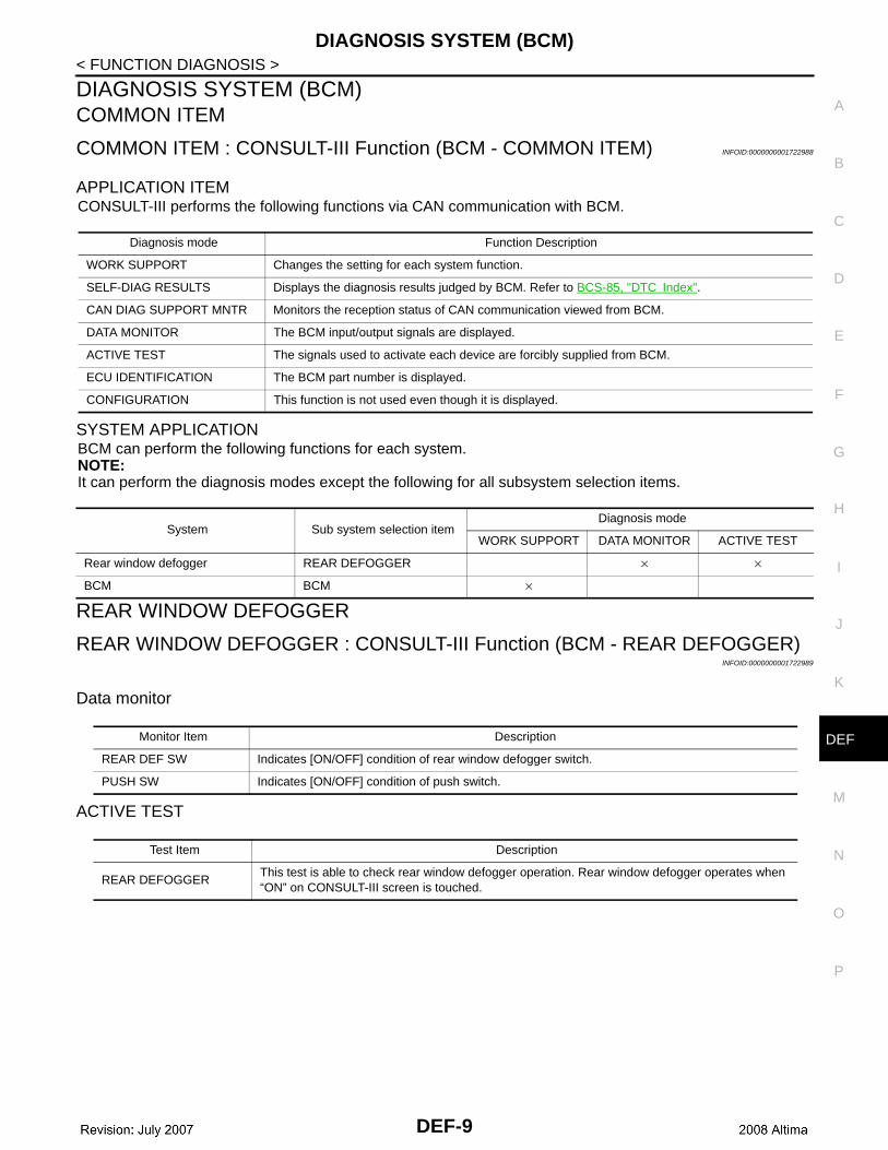
COMMON ITEM : CONSULT-III Function (BCM - COMMON ITEM) INFOID:0000000001722988
APPLICATION ITEMCONSULT-III performs the following functions via CAN communication with BCM.
SYSTEM APPLICATIONBCM can perform the following functions for each system.NOTE:It can perform the diagnosis modes except the following for all subsystem selection items.
REAR WINDOW DEFOGGER
REAR WINDOW DEFOGGER : CONSULT-III Function (BCM - REAR DEFOGGER)INFOID:0000000001722989
Data monitor
ACTIVE TEST
Diagnosis mode Function Description
WORK SUPPORT Changes the setting for each system function.
SELF-DIAG RESULTS Displays the diagnosis results judged by BCM. Refer to BCS-85, "DTC Index".
CAN DIAG SUPPORT MNTR Monitors the reception status of CAN communication viewed from BCM.
DATA MONITOR The BCM input/output signals are displayed.
ACTIVE TEST The signals used to activate each device are forcibly supplied from BCM.
ECU IDENTIFICATION The BCM part number is displayed.
CONFIGURATION This function is not used even though it is displayed.
System Sub system selection itemDiagnosis mode
WORK SUPPORT DATA MONITOR ACTIVE TEST
Rear window defogger REAR DEFOGGER × ×
BCM BCM ×
Monitor Item Description
REAR DEF SW Indicates [ON/OFF] condition of rear window defogger switch.
PUSH SW Indicates [ON/OFF] condition of push switch.
Test Item Description
REAR DEFOGGERThis test is able to check rear window defogger operation. Rear window defogger operates when “ON” on CONSULT-III screen is touched.
DEF-9
CAN COMMUNICATION
< FUNCTION DIAGNOSIS >CAN COMMUNICATION
System Description INFOID:0000000001722990
Refer to LAN-7, "System Description".
DEF-10

REAR WINDOW DEFOGGER SWITCH
C
D
E
F
G
H
I
J
K
M
A
B
EF
N
O
P
< COMPONENT DIAGNOSIS >
D
COMPONENT DIAGNOSISREAR WINDOW DEFOGGER SWITCH
Description INFOID:0000000001722991
• The rear window defogger is operated by turning the rear window defogger switch ON.• Turns the indicator lamp in the rear window defogger switch ON when operating the rear window defogger.
Component Function Check INFOID:0000000001722992
1. CHECK REAR WINDOW DEFOGGER SWITCH FUNCTION
Check that the indicator lamp of rear window defogger illuminates with rear window defogger switch ON.Is the inspection result normal?YES >> Rear window defogger switch function is OK.NO >> Refer to DEF-11, "Diagnosis Procedure".
Diagnosis Procedure INFOID:0000000001722993
1. CHECK CONTROLLER (AUTO AMP.) (REAR WINDOW DEFOGGER SWITCH)
Does controller (auto amp.) operate normally?Is the inspection result normal?YES >> Inspection End.NO >> GO TO 2
2. CHECK REAR WINDOW DEFOGGER SWITCH INDICATOR CIRCUIT
1. Turn ignition switch ON.2. Check voltage between controller (auto amp.) connector and
ground.
Is the inspection result normal?YES >> Repair or replace harness.NO >> Replace controller (auto amp.). Refer to VTL-8, "Removal and Installation".
Terminals
Condition of rear window defogger
switch
Voltage (V)(Approx.)
(+)
(–)Controller (auto amp.) connec-
torTerminal
M37 22 GroundON Battery voltage
OFF 0
ALLIA0174ZZ
DEF-11

REAR WINDOW DEFOGGER RELAY
< COMPONENT DIAGNOSIS >REAR WINDOW DEFOGGER RELAY
Description INFOID:0000000001722994
Power is supplied to the rear window defogger with BCM control.
Component Function Check INFOID:0000000001722995
1. CHECK REAR WINDOW DEFOGGER RELAY POWER SUPPLY CIRCUIT
Check that an operation noise of rear window defogger relay [located in fuse block (J/B)] can be heard whenturning the rear window defogger switch ON.Is the inspection result normal?YES >> Rear window defogger relay power supply circuit is OK.NO >> Refer to DEF-12, "Diagnosis Procedure".
Diagnosis Procedure INFOID:0000000001722996
1. CHECK REAR WINDOW DEFOGGER RELAY GROUND CIRCUIT
1. Turn ignition switch ON.2. Check voltage between BCM connector and ground.
Is the inspection result normal?YES >> Rear window defogger power supply circuit is OK.NO >> GO TO 2
2. CHECK HARNESS CONTINUITY
1. Turn ignition switch OFF.2. Disconnect BCM and fuse block (J/B).3. Check continuity between BCM connector (A) and fuse block (J/
B) connector (B).
Is the inspection result normal?YES >> GO TO 3NO >> Repair or replace harness.
3. CHECK REAR WINDOW DEFOGGER RELAY
Check rear window defogger relay.Refer to DEF-13, "Component Inspection".Is the inspection result normal?YES >> GO TO 4NO >> Replace rear window defogger relay.
4. CHECK INTERMITTENT INCIDENT
Check intermittent incident.Refer to GI-42, "Intermittent Incident"Is the inspection result normal?YES >> Check the following.
TerminalsCondition of rear window defogger
switch
Voltage (V)(Approx.)
(+)(–)
BCM connector Terminal
M18 59 GroundON 0
OFF Battery voltage
ALLIA0175ZZ
BCM connector TerminalFuse block (J/B)
connectorTerminal Continuity
M18 (A) 59 M4 (B) 4Q Yes
ALLIA0176ZZ
DEF-12

REAR WINDOW DEFOGGER RELAY
C
D
E
F
G
H
I
J
K
M
A
B
EF
N
O
P
< COMPONENT DIAGNOSIS >
D
• Battery power supply circuit.• Fuse block (J/B).
NO >> Repair or replace the malfunctioning parts.
Component Inspection INFOID:0000000001722997
1. CHECK REAR WINDOW DEFOGGER RELAY
Check rear window defogger relay.
Is the inspection result normal?YES >> Inspection End.NO >> Replace rear window defogger relay.
Terminal
Condition ContinuityRear window defogger relay
3 5
12V direct current supply between termi-nals 1 and 2.
Yes
No current supply No
SEF497Y
DEF-13
REAR WINDOW DEFOGGER POWER SUPPLY AND GROUND CIRCUIT
< COMPONENT DIAGNOSIS >REAR WINDOW DEFOGGER POWER SUPPLY AND GROUND CIRCUIT
Description INFOID:0000000001722998
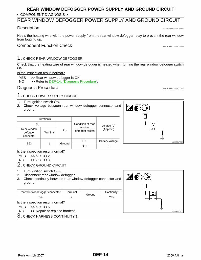
Heats the heating wire with the power supply from the rear window defogger relay to prevent the rear windowfrom fogging up.
Component Function Check INFOID:0000000001722999
1. CHECK REAR WINDOW DEFOGGER
Check that the heating wire of rear window defogger is heated when turning the rear window defogger switchON.Is the inspection result normal?YES >> Rear window defogger is OK.NO >> Refer to DEF-14, "Diagnosis Procedure".
Diagnosis Procedure INFOID:0000000001723000
1. CHECK POWER SUPPLY CIRCUIT
1. Turn ignition switch ON.2. Check voltage between rear window defogger connector and
ground.
Is the inspection result normal?YES >> GO TO 2NO >> GO TO 3
2. CHECK GROUND CIRCUIT
1. Turn ignition switch OFF.2. Disconnect rear window defogger.3. Check continuity between rear window defogger connector and
ground.
Is the inspection result normal?YES >> GO TO 5NO >> Repair or replace harness.
3. CHECK HARNESS CONTINUITY 1
Terminals
Condition of rear window
defogger switch
Voltage (V)(Approx.)
(+)
(–)Rear window defogger connector
Terminal
B53 1 GroundON Battery voltage
OFF 0
ALLIA0177ZZ
Rear window defogger connector TerminalGround
Continuity
B54 2 Yes
ALLIA0178ZZ
DEF-14

REAR WINDOW DEFOGGER POWER SUPPLY AND GROUND CIRCUIT
C
D
E
F
G
H
I
J
K
M
A
B
EF
N
O
P
< COMPONENT DIAGNOSIS >
D
1. Turn ignition switch OFF.2. Disconnect condenser and rear window defogger.3. Check continuity between condenser connector (A) and rear
window defogger connector (B).
Is the inspection result normal?YES >> GO TO 4NO >> Replace condenser. Refer to DEF-42, "Removal and
Installation - Coupe".
4. CHECK HARNESS CONTINUITY 2
1. Disconnect fuse block (J/B).2. Check continuity between fuse block (J/B) connector (A) and
condenser connector (B).
Is the inspection result normal?YES >> GO TO 6NO >> Replace or repair harness.
5. CHECK FILAMENT
Check filament.Refer to DEF-15, "Component Inspection".Is the inspection result normal?YES >> Refer to GI-42, "Intermittent Incident".NO >> Repair filament. Refer to DEF-40, "Inspection and Repair".
6. CHECK INTERMITTENT INCIDENT
Check intermittent incident.Refer to GI-42, "Intermittent Incident".Is the inspection result normal?YES >> Check the following.
• Battery power supply circuit.• Fuse block (J/B).
NO >> Repair or replace the malfunctioning parts.
Component Inspection INFOID:0000000001723001
1. CHECK FILAMENT
Check the filament for damage or open circuits.Refer to DEF-40, "Inspection and Repair".Is the inspection result normal?YES >> Inspection End.NO >> Repair filament. Refer to DEF-40, "Inspection and Repair".
Condenser connector
TerminalRear window defogger
connectorTerminal Continuity
B52 (A) 1 B53 (B) 1 Yes
ALLIA0179ZZ
Fuse block (J/B) connector
TerminalCondenser connector
Terminal Continuity
B4 (A)10T
B52 (B) 1 Yes11T
ALLIA0180ZZ
DEF-15

DRIVER SIDE DOOR MIRROR DEFOGGER
< COMPONENT DIAGNOSIS >DRIVER SIDE DOOR MIRROR DEFOGGER
Description INFOID:0000000001723002
Heats the heating wire with the power supply from the rear window defogger relay to prevent the door mirrorfrom fogging up.
Component Function Check INFOID:0000000001723003
1. CHECK DOOR MIRROR DEFOGGER LH
Check that heating wire of door mirror defogger LH is heated when turning the rear window defogger switchON.Is the inspection result normal?YES >> Door mirror defogger is OK.NO >> Refer to DEF-16, "Diagnosis Procedure".
Diagnosis Procedure INFOID:0000000001723004
1. CHECK POWER SUPPLY CIRCUIT
1. Turn ignition switch OFF.2. Disconnect door mirror LH. 3. Turn ignition switch ON.4. Check voltage between door mirror LH connector and ground.
Is the inspection result normal?YES >> GO TO 2NO >> Repair or replace harness.
2. CHECK GROUND CIRCUIT
1. Turn ignition switch OFF.2. Check continuity between door mirror LH connector and ground.
Is the inspection result normal?YES >> GO TO 3NO >> Repair or replace harness.
3. CHECK DOOR MIRROR DEFOGGER LH
Check door mirror defogger LH.Refer to DEF-17, "Component Inspection".Is the inspection result normal?YES >> GO TO 4NO >> Replace door mirror. Refer to MIR-19, "Removal and Installation".
4. CHECK INTERMITTENT INCIDENT
Check intermittent incident.
TerminalsCondition of rear window
defogger switch
Voltage (V)(Approx.)
(+)
(–)Door mirror LH connector
Terminal
D4 1 GroundON Battery voltage
OFF 0
ALLIA0181ZZ
Door mirror LH connector TerminalGround
Continuity
D4 2 Yes
ALLIA0184ZZ
DEF-16

DRIVER SIDE DOOR MIRROR DEFOGGER
C
D
E
F
G
H
I
J
K
M
A
B
EF
N
O
P
< COMPONENT DIAGNOSIS >
D
Refer to GI-42, "Intermittent Incident".Is the inspection result normal?YES >> Check the following.
• Battery power supply circuit.• Fuse block (J/B).
NO >> Repair or replace the malfunctioning parts.
Component Inspection INFOID:0000000001723005
1. CHECK DOOR MIRROR DEFOGGER LH
1. Turn ignition switch OFF.2. Disconnect door mirror LH.3. Check continuity between door mirror terminals.
Is the inspection result normal?YES >> Inspection End.NO >> Replace door mirror LH. Refer to MIR-19, "Removal and
Installation".
Terminal Continuity
1 2 Yes
ALLIA0185ZZ
DEF-17

PASSENGER SIDE DOOR MIRROR DEFOGGER
< COMPONENT DIAGNOSIS >PASSENGER SIDE DOOR MIRROR DEFOGGER
Description INFOID:0000000001723006
Heats the heating wire with the power supply from the rear window defogger relay to prevent the door mirrorfrom fogging up.
Component Function Check INFOID:0000000001723007
1.CHECK DOOR MIRROR DEFOGGER RH
Check that the heating wire of door mirror defogger RH is heated when turning the rear window defoggerswitch ON.Is the inspection result normal?YES >> Door mirror defogger RH is OK.NO >> Refer to DEF-18, "Diagnosis Procedure".
Diagnosis Procedure INFOID:0000000001723008
1. CHECK POWER SUPPLY CIRCUIT
1. Turn ignition switch OFF.2. Disconnect door mirror RH.3. Turn ignition switch ON.4. Check voltage between door mirror RH connector and ground.
Is the inspection result normal?YES >> GO TO 2NO >> Repair or replace harness.
2. CHECK GROUND CIRCUIT
1. Turn ignition switch OFF.2. Check continuity between door mirror RH connector and
ground.
Is the inspection result normal?YES >> GO TO 3NO >> Repair or replace harness.
3. CHECK PASSENGER SIDE DOOR MIRROR DEFOGGER
Check door mirror defogger RH.Refer to DEF-19, "Component Inspection".Is the inspection result normal?YES >> GO TO 4NO >> Replace door mirror RH. Refer to MIR-19, "Removal and Installation".
4. CHECK INTERMITTENT INCIDENT
Check intermittent incident.
TerminalsCondition of rear window defogger
switch
Voltage (V)(Approx.)
(+)
(–)Door mirror RH connector
Terminal
D107 1 GroundON Battery voltage
OFF 0
ALLIA0181ZZ
Door mirror RH connector TerminalGround
Continuity
D107 2 Yes
ALLIA0184ZZ
DEF-18

PASSENGER SIDE DOOR MIRROR DEFOGGER
C
D
E
F
G
H
I
J
K
M
A
B
EF
N
O
P
< COMPONENT DIAGNOSIS >
D
Refer to GI-42, "Intermittent Incident".Is the inspection result normal?YES >> Check the following.
• Battery power supply circuit.• Fuse block (J/B).
NO >> Repair or replace the malfunctioning parts.
Component Inspection INFOID:0000000001723009
1. CHECK DOOR MIRROR DEFOGGER RH
1. Turn ignition switch OFF.2. Disconnect door mirror RH.3. Check continuity between door mirror terminals.
Is the inspection result normal?YES >> Inspection End.NO >> Replace door mirror RH. Refer to MIR-19, "Removal
and Installation".
Terminal Continuity
1 2 Yes
ALLIA0185ZZ
DEF-19

BCM (BODY CONTROL MODULE)
< ECU DIAGNOSIS >ECU DIAGNOSISBCM (BODY CONTROL MODULE)
Reference Value INFOID:0000000001723010
VALUES ON THE DIAGNOSIS TOOL
TERMINAL LAYOUTRefer to BCS-45, "Terminal Layout".
PHYSICAL VALUESRefer to BCS-45, "Physical Values".
Monitor Item Condition Value/Status
REAR DEF SWNOTE:The item is indicated, but not monitored.
OFF
DEF-20

BCM (BODY CONTROL MODULE)
C
D
E
F
G
H
I
J
K
M
A
B
EF
N
O
P
< ECU DIAGNOSIS >
D
Wiring Diagram - Coupe INFOID:0000000001723011
AWLWA0018GB
DEF-21

BCM (BODY CONTROL MODULE)
< ECU DIAGNOSIS >ALLIA0041GB
DEF-22

BCM (BODY CONTROL MODULE)
C
D
E
F
G
H
I
J
K
M
A
B
EF
N
O
P
< ECU DIAGNOSIS >
D
AWIIA0637GB
DEF-23

BCM (BODY CONTROL MODULE)
< ECU DIAGNOSIS >AWIIA0638GB
DEF-24

BCM (BODY CONTROL MODULE)
C
D
E
F
G
H
I
J
K
M
A
B
EF
N
O
P
< ECU DIAGNOSIS >
D
AWIIA0639GB
DEF-25

BCM (BODY CONTROL MODULE)
< ECU DIAGNOSIS >AWIIA0640GB
DEF-26

BCM (BODY CONTROL MODULE)
C
D
E
F
G
H
I
J
K
M
A
B
EF
N
O
P
< ECU DIAGNOSIS >
D
Wiring Diagram - Sedan INFOID:0000000003221692
AWLWA0155GB
DEF-27

BCM (BODY CONTROL MODULE)
< ECU DIAGNOSIS >ALLIA0041GB
DEF-28

BCM (BODY CONTROL MODULE)
C
D
E
F
G
H
I
J
K
M
A
B
EF
N
O
P
< ECU DIAGNOSIS >
D
AWLIA0500GB
DEF-29
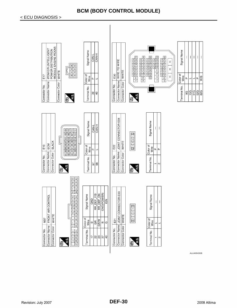
BCM (BODY CONTROL MODULE)
< ECU DIAGNOSIS >ALLIA0043GB
DEF-30

BCM (BODY CONTROL MODULE)
C
D
E
F
G
H
I
J
K
M
A
B
EF
N
O
P
< ECU DIAGNOSIS >
D
AWLIA0501GB
DEF-31

BCM (BODY CONTROL MODULE)
< ECU DIAGNOSIS >AWLIA0502GB
DEF-32

REAR WINDOW DEFOGGER AND DOOR MIRROR DEFOGGER DO NOT OPER-ATE.
C
D
E
F
G
H
I
J
K
M
A
B
EF
N
O
P
< SYMPTOM DIAGNOSIS >
D
SYMPTOM DIAGNOSISREAR WINDOW DEFOGGER AND DOOR MIRROR DEFOGGER DO NOTOPERATE.
Diagnosis Procedure INFOID:0000000001723012
1. CHECK REAR WINDOW DEFOGGER SWITCH
Check rear window defogger switch.Refer to DEF-14, "Component Function Check".Is the inspection result normal?YES >> GO TO 2NO >> Repair or replace the malfunctioning parts.
2. CHECK REAR WINDOW DEFOGGER RELAY
Check rear window defogger relay.Refer to DEF-12, "Component Function Check".Is the inspection result normal?YES >> Refer to GI-42, "Intermittent Incident".NO >> Repair or replace the malfunctioning parts.
DEF-33

REAR WINDOW DEFOGGER DOES NOT OPERATE BUT BOTH OF DOOR MIR-ROR DEFOGGER OPERATE.
< SYMPTOM DIAGNOSIS >
REAR WINDOW DEFOGGER DOES NOT OPERATE BUT BOTH OF DOORMIRROR DEFOGGER OPERATE.
Diagnosis Procedure INFOID:0000000001723013
1. CHECK REAR WINDOW DEFOGGER POWER SUPPLY AND GROUND CIRCUIT
Check rear window defogger power supply and ground circuit.Refer to DEF-14, "Component Function Check".Is the inspection result normal?YES >> Refer to GI-42, "Intermittent Incident".NO >> Repair or replace the malfunctioning parts.
DEF-34

BOTH DOORS MIRROR DEFOGGER DON’T OPERATE BUT REAR WINDOW DEFOGGER OPERATES
C
D
E
F
G
H
I
J
K
M
A
B
EF
N
O
P
< SYMPTOM DIAGNOSIS >
D
BOTH DOORS MIRROR DEFOGGER DON’T OPERATE BUT REAR WIN-DOW DEFOGGER OPERATES
Diagnosis Procedure INFOID:0000000001723014
1. CHECK INTERMITTENT INCIDENT
Check intermittent incident.Refer to GI-42, "Intermittent Incident".Is the inspection result normal?YES >> Check the following.
• Battery power supply circuit.• Fuse block (J/B).
NO >> Repair or replace the malfunctioning parts.
DEF-35

DRIVER SIDE DOOR MIRROR DEFOGGER DOES NOT OPERATE.
< SYMPTOM DIAGNOSIS >DRIVER SIDE DOOR MIRROR DEFOGGER DOES NOT OPERATE.
Diagnosis Procedure INFOID:0000000001723015
1. CHECK DOOR MIRROR DEFOGGER LH
Check door mirror defogger LH.Refer to DEF-16, "Component Function Check".Is the inspection result normal?YES >> Refer to GI-42, "Intermittent Incident".NO >> Repair or replace the malfunctioning parts.
DEF-36

PASSENGER SIDE DOOR MIRROR DEFOGGER DOES NOT OPERATE.
C
D
E
F
G
H
I
J
K
M
A
B
EF
N
O
P
< SYMPTOM DIAGNOSIS >
D
PASSENGER SIDE DOOR MIRROR DEFOGGER DOES NOT OPERATE.
Diagnosis Procedure INFOID:0000000001723016
1. CHECK DOOR MIRROR DEFOGGER RH
Check door mirror defogger RH.Refer to DEF-18, "Component Function Check".Is the inspection result normal?YES >> Refer to GI-42, "Intermittent Incident".NO >> Repair or replace the malfunctioning parts.
DEF-37
REAR WINDOW DEFOGGER SWITCH DOES NOT LIGHT, BUT REAR WINDOW DEFOGGER OPERATES
< SYMPTOM DIAGNOSIS >
REAR WINDOW DEFOGGER SWITCH DOES NOT LIGHT, BUT REAR WIN-DOW DEFOGGER OPERATES
Diagnosis Procedure INFOID:0000000001723017
1. CHECK FRONT AIR CONTROL (REAR WINDOW DEFOGGER SWITCH)
Check that the front air control (rear window defogger switch) is operating normally.OK or NGOK >> Refer to GI-42, "Intermittent Incident".NG >> Refer to DEF-11, "Diagnosis Procedure".
DEF-38

PRECAUTIONS
C
D
E
F
G
H
I
J
K
M
A
B
EF
N
O
P
< PRECAUTION >
D
PRECAUTIONPRECAUTIONS
Supplemental Restraint System (SRS) "AIR BAG" and "SEAT BELT PRE-TENSION-ER" INFOID:0000000001342637
The Supplemental Restraint System such as “AIR BAG” and “SEAT BELT PRE-TENSIONER”, used alongwith a front seat belt, helps to reduce the risk or severity of injury to the driver and front passenger for certaintypes of collision. This system includes seat belt switch inputs and dual stage front air bag modules. The SRSsystem uses the seat belt switches to determine the front air bag deployment, and may only deploy one frontair bag, depending on the severity of a collision and whether the front occupants are belted or unbelted.Information necessary to service the system safely is included in the SR and SB section of this Service Man-ual.WARNING:• To avoid rendering the SRS inoperative, which could increase the risk of personal injury or death in
the event of a collision which would result in air bag inflation, all maintenance must be performed byan authorized NISSAN/INFINITI dealer.
• Improper maintenance, including incorrect removal and installation of the SRS, can lead to personalinjury caused by unintentional activation of the system. For removal of Spiral Cable and Air BagModule, see the SR section.
• Do not use electrical test equipment on any circuit related to the SRS unless instructed to in thisService Manual. SRS wiring harnesses can be identified by yellow and/or orange harnesses or har-ness connectors.
DEF-39

FILAMENT
< ON-VEHICLE REPAIR >ON-VEHICLE REPAIRFILAMENT
Inspection and Repair INFOID:0000000001342638
INSPECTION1. When measuring voltage, wrap tin foil around the top of the neg-
ative probe. Then press the foil against the wire with your finger.
2. Attach probe circuit tester (in Volt range) to middle portion ofeach filament.
3. If a filament is burned out, circuit tester registers 0 or batteryvoltage.
4. To locate burned out point, move probe to left and right along fil-ament. Test needle will swing abruptly when probe passes thepoint.
REPAIR
REPAIR EQUIPMENT• Conductive silver composition (Dupont No. 4817 or equivalent)
SEL122R
SEL263
SEL265
DEF-40
FILAMENT
C
D
E
F
G
H
I
J
K
M
A
B
EF
N
O
P
< ON-VEHICLE REPAIR >
D
• Ruler 30 cm (11.8 in) long• Drawing pen• Heat gun• Alcohol• Cloth
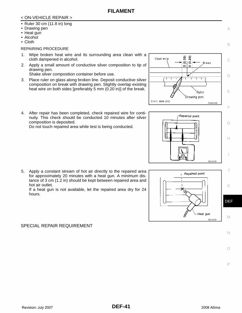
REPAIRING PROCEDURE
1. Wipe broken heat wire and its surrounding area clean with acloth dampened in alcohol.
2. Apply a small amount of conductive silver composition to tip ofdrawing pen.Shake silver composition container before use.
3. Place ruler on glass along broken line. Deposit conductive silvercomposition on break with drawing pen. Slightly overlap existingheat wire on both sides [preferably 5 mm (0.20 in)] of the break.
4. After repair has been completed, check repaired wire for conti-nuity. This check should be conducted 10 minutes after silvercomposition is deposited.Do not touch repaired area while test is being conducted.
5. Apply a constant stream of hot air directly to the repaired areafor approximately 20 minutes with a heat gun. A minimum dis-tance of 3 cm (1.2 in) should be kept between repaired area andhot air outlet.If a heat gun is not available, let the repaired area dry for 24hours.
SPECIAL REPAIR REQUIREMENT
PIIA0215E
SEL012D
SEL013D
DEF-41

CONDENSER
< ON-VEHICLE REPAIR >CONDENSER
Removal and Installation - Coupe INFOID:0000000001342640
REMOVAL1. Remove the rear seat cushion and the rear seat back.
Refer to SE-23, "Removal and Installation".2. Remove the rear kick plate, rear wheel well garnish and the rear pillar finisher.
Refer to INT-18, "Removal and Installation".3. Disconnect the connectors (A), remove bolt (B), and then
remove condenser (1) from the vehicle body.
INSTALLATIONInstallation is in the reverse order of removal.
Removal and Installation - Sedan INFOID:0000000003110906
REMOVAL1. Remove the rear seat cushion and the rear seat back.
Refer to SE-48, "Removal and Installation".2. Remove the rear kickplate, rear wheel well garnish and the rear pillar finisher.
Refer to INT-34, "Removal and Installation".3. Disconnect the electrical connector, remove bolt (A), and then
remove condenser (1) from the vehicle body.
INSTALLATIONInstall in the reverse order of removal.
ALLIA0658GB
JMLIA0013ZZ
DEF-42