Embed Size (px)
Citation preview

Dream Fabric FrameAssembly Instructions
Copyright January 1, 2016Jim M. Bagley, GraceWood, Inc(Reproduction Prohibited)Version 2.4

Table Of ContentsParts List 3Step 1: Table Set Up 6Step 2: Install the Hand Wheel 8Step 3: Install the Front Rail 8Step 4: Top Plate Assembly 11Step 5: Place the Sewing Machine 12Step 6: Install the Back Rail 13Step 7: Adjust Fabric Height 15Step 8: Control Box Set-up 16Step 9: Sure Stitch Installation 17
2
3
2.5mm Allen Wrench (1)
Sure Stitch Box
Back Rail Clamp (3)
Front Rail Clamp (2)Front Rail (1)
Back Rail (1)
Table Top (1)
Power Supply (1)
Encoder with Encoder Cable(2)
Control Box (1)
Box 1
Box 2
Display Box (1)
Ziptie (8) Ziptie Mount (6) Velcro Strap (6)
Sure Stitch Display Cable (1) Sure Stitch Sewing Machine Cable (1)
Parts List
Cloth Leaders (4)

Inner Box 3
4
Left Leg (1) Right Leg (1)
Sewing Machine Clamp (4)Top Plate (1)
Bottom Plate (1)
Carriage Bolt and Clamp (1)
Side Rail Clamp (2)
Handle Crossbar (1)
Handle Left (1) Handle Right (1)
Box 2 Continued
Bungee Clamp with Bungee Stop (4)
Inner Box 1
Inner Box 2

5
3mm Allen Wrench (1)
5mm Allen Wrench (1)
6mm Allen Wrench (1)
M8 x 16mm SBHCS (20)M6 x 10mm SBHCS (4)
M10 Washer (1) M10 x 80mm SBHCS (1)
17mm Open End Wrench (1)
M8 x 85mm Shoulder Bolt (1)
4mm Allen Wrench (1)
Inner Box 5
Inner Box 4
M8 x 50mm SBHCS (5)
Fabric Hook Holder (5)Corner Brace (4)
Long Knob (1)Large Hand Wheel (1)
Box 2 Continued

Parts Needed:Step 1: Table Set Up
6
1. Right Leg (1)2. Left Leg (1)3. Table Top (1)4. M8 x 16mm SBHCS (25)5. 5mm Allen Wrench (1)6. 4mm Allen Wrench (1)7. Corner Brace (4)
Average sitting height is 4 holes from bottom
1-3 Replace each Height Screw and tighten each Centering Screw
Height Screw
1-1 Remove Height Screws and Loosen Centering Screws
Height Screw
Centering Screws
1-2 Adjust Table height

7
1-6 Tilt Table Upright 1-7 Attach Corner Braces to each corner
1-4 Attach Hooks to Table
M8 x 50mm SBHCS
1-5 Attach Legs to Table with the Hooks facing the front of the Legs.
M8 x 16mm SBHCS
Note: Leave bolts loose, they will be tightened in a further step.
Note: Leave screws loose, they will be tightened in a further step.
M8 x 16mm SBHCS (4)
Front
Rear

Parts Needed:
Parts Needed:
1. 6mm Allen Wrench (1)2. Large Hand Wheel (1)3. Long Knob (1)4. M10 Washer (1)5. M8 x 85mm Shoulder Bolt (1)6. M10 x 80mm SBHCS (1)
1. Front Rail (1)2. 3mm Allen Wrench (1)3. 5mm Allen Wrench (1)
Step 2: Install the Hand Wheel
Step 3: Install the Front Rail
2-1 Attach the Long Knob
3-1 Remove Rail End Cap on each Front Corner Post
8
2-2 Attach the Large Hand Wheel
M8 x 85mm Shoulder Bolt
M10 Washer
M10 x 80mm SBHCS
3-2 Insert Front Rail into the right Front Corner Post
Align grooves in handwheel with
hand wheel collar
Note: Make sure gears engage before moving on. If gears are not properly engaged pull legs in/out to align gears.

9
3-3 Re-install Rail End Cap onto the right Front Corner PostNote: Be sure the side rails and front rail line up so that a long rubber edge on each rail is the highest part of each rail before installing cap.
Rubber edge is highest part of rails
3-6 Re-install Rail End Cap onto the left Front Corner PostNote: Be sure the side rails and front rail line up so that a long rubber edge on each rail is the highest part of each rail before installing cap.
Rubber edge is highest part of rails
You may need to tilt the top of the Leg inward
3-5 Insert Front Rail into the left Front Corner Post
3-4 Tighten each bolt with the Allen Wrench oriented verticle as shown in Fig. 3-4a until difficult to turn, then turn each bolt 1/4 a rotation with the Allen Wrench oriented horizontal as shown in Fig. 3-4b.
Fig. 3-4a Fig. 3-4b

10
3-8 Tighten the (4) loose screws on the underside of the table from Step 1-5
3-9 Tighten (16) loose screws on the Coner Braces from Step 1-7
3-7 Tighten each bolt with the Allen Wrench oriented verticle as shown in Fig. 3-7a until difficult to turn, then turn each bolt 1/4 rotation with the Allen Wrench oriented horizontal as shown in Fig. 3-7b.
Fig. 3-7a Fig. 3-7b

11
4-4 Place Bottom Plate onto Frame and Top Plate onto Bottom Plate
Parts Needed:1. Right Handle (1)2. Left Handle (1)3. Top Plate (1)4. Handle Crossbar (1)5. Carriage Bolt and Clamp (1)6. Bottom Plate (1)7. M6 x 10mm SBHCS (4)8. 4mm Allen Wrench (1)
Step 4: Top Plate Assembly
4-2 Un-thread Clamp from Carriage Bolt 4-3 Assemble Cross Brace with Carriage Bolt and Clamp
4-1 Attach Handles
M6 x 10mm SBHCS (4)
*Note: the Carriage Bolt may need to be twisted to pass through both handles.
*Note: Make sure Bottom Plate is Oriented with Sewing Machine Stop towards back of frame
Sewing Machine
Stop
*Note: may need to loosen screws in cross brace to get carriage bolt through , then retighten screws

Parts Needed:1. Sewing Machine2. Cam Clamp (4)
Step 5: Place the Sewing Machine
12
5-1 Place Sewing Machine onto Top Plate using the placement instructions below. Slide each Clamp into the grooves on the Top Plate and lock against Machine.
Note: Innovis XV 8500D will not use the Front 2 Clamps.
Brother 1500:Center from front to back and from side to side.Center from side to side. Align the back of the
throat with the verticle handlebar
Innovis VQ 2400; Innovis XV 8500D:Placement Instructions:

13
6-3 Loosen each Knob on the back of each Rail Holder
6-4 Insert Back Rail through the throat of the Sewing Machine
Note: You may need to pull rails upward to allow the levers to be pressed in.
Final height will be adjusted in later step.
Parts Needed:1. Back Rail (1)2. 4mm Allen Wrench (1)
Step 6: Install the Back Rail
6-2 Raise Rails to Top Slot6-1 Loosen the Set Screws on each Corner Post

14
6-6 Insert the right end of the Back Rail into the right back Rail Holder
6-5 Insert the left end of the Back Rail into the left back Rail Holder
6-7 Tighten each Knob on the back of each Rail Holder
6-8 Adjust leveling feet height until table is level using the (1) 17mm Open End Wrench
Heighten Table
Lower Table

Parts Needed:1. 4mm Allen Wrench (1)
Step 7: Adjust Fabric Height
7-2 Tighten set screws in Rail Holders
1/4 in Above
Machine
7-1 Move Back Rail 1/4” above Machine
15
Note: refer to step 6-2 for instructions on how to raise and lower the rails.
7-3 Move the Sewing Machine so that the Needle is 1” away from the Back Rail. Hold the Machine in place as you adjust the Carriage Stop by loosening the knob and sliding the Sewing Machine stop against the back wheel. This will be adjusted again in the Fabric Installation instructions.
KnobSewing Machine Stop
Needle 1in away from Back Rail
Note: Do not over tighten set screws.

16
8-2 Move the Control Jumpers to the correct pins based on your Machine Model.
8-1 Open the Control Box
Parts Needed:1. Control box
Step 8: Control Box Set-up
JP1
J3
10 1 2 3
Brother 1500S:
JP1: ON JP2: ON JP3: OFFJP4: OFFJ3-4 ON
Innovis 1500D,Innovis 2500D,Innovis 4500D:
JP1
J3
10 1 2 3
JP1: OFFJP2: ON JP3: ON JP4: OFFJ3-2 ON
JP1
J3
10 1 2 3
Innovis VQ2400, Innovis VM6200, Innovis XV8500D, NV6000D, NV6700, NV6750D, Innovis VM 5100Note: 6000 series machines are not multifunction compatible
JP1: OFFJP2: OFFJP3: ON JP4: ONJ3: OFF

9-2 Clamp Display Box onto Crossbar next to the Handle on the Left or Right Side
17
9-3 Secure the Display Box with (1) M4 x 16mm SBHCS
Parts Needed:1. Display Box (1)2. Control Box (1)3. Sure Stitch Display Cable (1)4. Sewing Machine Cable (1)5. Power Supply (1)6. Encoder with Encoder Cable(2)7. Velcro Strap (6)8. Zip Tie (8)9. Zip Tie Mount (6)10. M4 x 16mm SBHCS (1)11. M6 x 20mm SBHCS (2)12. 4mm Allen Wrench (1)13. 2.5mm Allen Wrench (1)
Step 9: Sure Stitch Installation
Display Box
M4 x 16mm SBHCS
9-1 Remove (1) M4 x 16mm SBHCS from Display Box
M4 x 16mm SBHCS
18
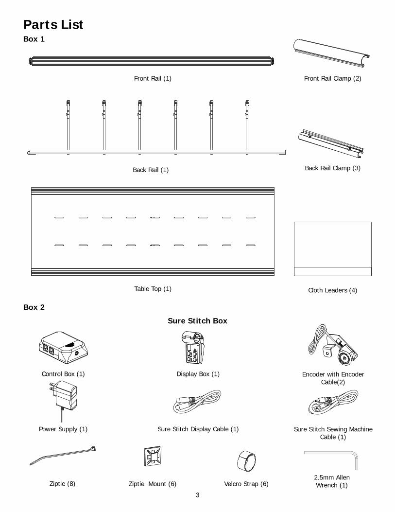
Control Box
9-5 Place Control Box on back of Machine
9-6 Plug in one end of the Display Cable into the Display Box
9-7 Plug in the other end of the Display Cable into the Control Box
9-4 Remove Sticky Tape Paper Backing from Control Box
Note: Be sure the arrow is on the back
side of the Cable

9-8 Use the Velcro Straps to Secure Display Cable
Velcro (x5)
9-9 Remove Back Right Wheel and Screw from Top Plate
19
9-11 Remove Back Left Wheel and Screw from Bottom Plate
9-10 Install Encoder to Top Plate with M6 x 20mm SBHCS and Removed Wheel
M6 x 20mm SBHCS
Note: Rotate Encoder until the Encoder Spring is partially compressed and then tighten the M6 X 20mm SBHCS for better accuracy.
Back Right Wheel from Top Plate
Back Right Wheel from Top Plate
Back of Frame
Back of Frame
Bottom Plate
Bottom Plate
Top Plate
Top Plate
Back Left Wheel from Bottom Plate
Back Left Wheel from Bottom Plate

20
9-14 Plug in Power Supply to Control Box 9-15 Plug Power Supply to an outlet.Note: Plug in Sure Stitch unit before sewing machine is turned on, or an error may occur.
9-13 Plug Encoder Cables into Control Box9-12 Install Encoder to Bottom Plate with M6 x 20mm SBHCS and Removed Wheel
M6 x 20mm SBHCS
Note: Rotate Encoder until the Encoder Spring is partially compressed and then tighten the M6 X 20mm SBHCS for better accuracy.
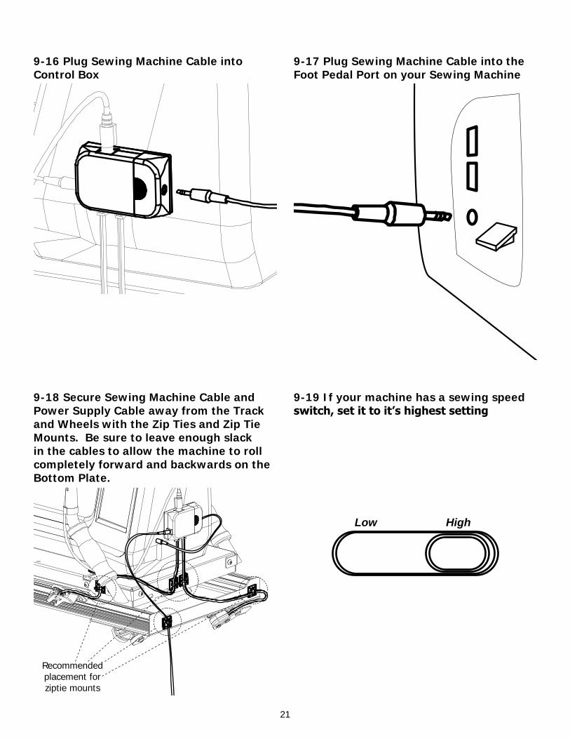
9-16 Plug Sewing Machine Cable into Control Box
21
9-17 Plug Sewing Machine Cable into the Foot Pedal Port on your Sewing Machine
9-19 If your machine has a sewing speed switch, set it to it’s highest setting
9-18 Secure Sewing Machine Cable and Power Supply Cable away from the Track and Wheels with the Zip Ties and Zip Tie Mounts. Be sure to leave enough slack in the cables to allow the machine to roll completely forward and backwards on the Bottom Plate.
HighLow
Recommended placement for ziptie mounts

22
Note: When the SureStitch is in the “on” mode, the sewing machine WILL BEGIN TO STITCH! When you stop moving the machine, it will continue to stitch at the sewing machine’s minimum speed until you press the off button. This feature ensures the machine will maintain as consistent a stitch length as possible with the intial movement of the machine.
On/Off Button: The On/Off button activates/disables the regulated stitch feature of the SureStitch. When the regulated stitch is active, the green LED light directly above the button will be lit. In regulated mode, your sewing machine will automatically adjust the speed that it stitches based on how fast you move your sewing machine around on the quilting frame. If you move your sewing machine too fast, it will reach its maximum stitch speed, and no longer be able to stitch fast enough to keep a constant stitch size. The green LED above the On/Off button will turn red when your sewing machine has reached it’s maximum stitch speed. When the LED above the On/Off button is lit red, your stitches will be longer than your set size.
Pulse Button: To activate the machines multifunctions, press and release the Pulse Button quickly for a single stitch occurs. Cut the thread by pressing and holding the Pulse Button until a beep is heard.
Stitch Length Buttons: Use the Stitch Length buttons to adjust how long your stitches will be while using the regulated stitch mode. The LED display directly above the Stitch Length buttons displays your current Stitch Length setting. You can set the Stitch Length from “1” to “10”, with a lower number having a shorter stitch and a higher number having a longer stitch. The stitch length setting does not indicate “Stitches per inch”, but will be consistent based on your sewing machine. The Stitch Length setting will be set to “5” every time you turn on the SureStitch.
9-20 Sewing Machine Controls
TM
Stitch Length Display
Active (Green)/Over-speed (Red)