Embed Size (px)
Citation preview

PROJECT REPORT ON HYPERTERMINAL DATA
TRANSMISSION AND RECEPTION USING
LABVIEW
Submitted by:-
Dikshya Shree Rath National Institute of technology, Rourkela
Submitted in Partial
fulfillment of Summer
Vocational Training
(May-July 2014), in
Integrated Test Range,
Defence Research and
Development
Organisation,
Chandipur, Odisha

1 | P a g e
CONTENTS
PREFACE ................................................................................................................................................. 2
ACKNOWLEDGEMENT ............................................................................................................................ 3
BONAFIDE CERTIFICATE ......................................................................................................................... 4
ABOUT DRDO ......................................................................................................................................... 5
ITR:- ........................................................................................................................................................ 7
OBJECTIVE .............................................................................................................................................. 8
REQUIREMENTS:- ................................................................................................................................... 8
SOFTWARE AND CONCEPT USED ........................................................................................................... 8
VIRTUAL INSTRUMENTATION:- .......................................................................................................... 8
LabVIEW:- ........................................................................................................................................... 8
THEORY AND EXPLANATION .................................................................................................................. 9
UNICAST:- ......................................................................................................................................... 11
MULTICAST:- ..................................................................................................................................... 12
IP ADRESSING:- ................................................................................................................................. 12
RS232:- ............................................................................................................................................. 13
LAN:- ................................................................................................................................................. 14
WAN:- ............................................................................................................................................... 14
EHTERNET:-....................................................................................................................................... 15
NETWORK TIME PROTOCOL:- .......................................................................................................... 16
PRECISION TIME PROTOCOL ............................................................................................................ 16
LOGIC:- ................................................................................................................................................. 17
CIRCUIT DIAGRAM:- ............................................................................................................................. 18
BLOCKS AND COMPONENTS USED:- .................................................................................................... 21
OUTPUT:- ............................................................................................................................................. 25
APPLICATIONS:- .................................................................................................................................... 26
CONCLUSION:- ..................................................................................................................................... 27
REFERENCES ......................................................................................................................................... 28

2 | P a g e
PREFACE
The importance of serial communication using COM ports is farfetched due to its many advantages
and fabricating such a circuit which uses the benefits of serial communication to establish
synchronization between the systems using virtual instrumentation was definitely an innovative
and challenging one.
It provided a conceptual understanding of LabVIEW software and its components and helped in
understanding various building blocks in networking systems and their protocols and procedures
which is not provided in daily lectures in class room due to the fact that it is advance knowledge in
this field. The project gives awareness of what is going on inside a Network time protocol system
and how the Central time division unit works. The purpose of this project is to design and simulate
circuit which derives data from same and correctly displays it and transmits it to other PCs (Client
PC) using multicast and unicast methods of transmission which have their own uniqueness and
application.

3 | P a g e
ACKNOWLEDGEMENT
I would like to express my gratitude and appreciation to all those who gave me the possibility to
complete this report. A special thanks to my project Coordinator, Shri. Soumitra Ray whose help,
stimulating suggestions and encouragement, helped me to coordinate my project especially in
writing this report. I am really thankful for his full efforts in guiding the team in achieving the goal as
well as his encouragement to maintain our progress in track.
I would also like to acknowledge with much appreciation the crucial role of the staff of Central timing
Department, ITR, DRDO who gave the permission to use all required machinery and the necessary
material to complete the project
A special thanks goes to my team mates, who helped me to assemble the parts and gave suggestion
about how the simulation can be done easily and efficiently. Working with them was indeed a
pleasure
I am grateful to the MTO, for providing me a good transportation facility and Officer-in-charge
Technical Information Center for allowing to use the well organized and rich Knowledge Centre
facility. In the process I might have missed some other department of this establishment who might
have extended me their support in making my stay in this establishment memorable, I wish to thank
them for their support.
Last but not least, many thanks go to Mr.C.R Ojha, Group officer, Human Resource and Development
Department who gave us this opportunity to carry out this training and complete this project.
Dikshya Shree Rath Department of Electronics and Communication National Institute of Technology, Rourkela

4 | P a g e
BONAFIDE CERTIFICATE
This is to certify that this project report entitled “HyperTerminal Data Transmission using LabVIEW” submitted to “INTEGRATED TEST RANGE, DEFENCE RESEARCH AND DEVELOPMENT ORGANISATION, CHANDIPUR, ODISHA”, is a bonafide record of work done by Dikshya Shree Rath, B.Tech, Department of Electronics and Communication, National Institute of Technology, Rourkela under supervision of Mr. Soumitra Ray,
Scientist “C”, CENTRAL TIMING &TELECOMMAND DIVISION from 5th May to 30th June, 2014. During this period she worked under my guidance and supervision. She
has successfully completed the above Projects assigned by me. During her Training she was sincere and showed keen interest in doing her Projects, thus completing it in stipulated time.
Mr. Soumitra Ray Mr. B. Biswas
Scientist “C” Scientist”C”
(Guide) (Reviewer)
Shri RAKESH BARUA
Scientist”F” Off. Additional Director (H)
Counter signed by
C. R. OJHA Group Director (HR)
Integrated Test Range Defence research and development organisation
Chandipur, Balasore
5 | P a g e
ABOUT DRDO
Defence Research & Development Organisation (DRDO) works under Department of Defence
Research and Development of Ministry of Defence. DRDO dedicatedly working towards enhancing
self-reliance in Defence Systems and undertakes design & development leading to production of
world class weapon systems and equipment in accordance with the expressed needs and the
qualitative requirements laid down by the three services.
DRDO is one of the prestigious organizations of the country in the field of Science and Technology,
which could transform our country’s Defense force into one of the most modern and powerful force
in the world. It was established by merging together the Scientific and Technical Development
Establishment under three services headquarters in 1958, with the aim of creating an organization
that can take up the challenges of developing and delivering the high technology in the field of
modern warfare, weapon system, avionics and other scientific aspects of nation’s defense. It has also
got mandate to modernize Defense Technology
DRDO is working in various areas of military technology which include aeronautics, armaments,
combat vehicles, electronics, instrumentation engineering systems, missiles, materials, naval
systems, advanced computing, simulation and life sciences. DRDO while striving to meet the Cutting
edge weapons technology requirements provides ample spinoff benefits to the society at large
thereby contributing to the nation building.
Vision
Make India prosperous by establishing world-class science and technology base and provide our
Defence Services decisive edge by equipping them with internationally competitive systems and
solutions.
Mission
Design, develop and lead to production state-of-the-art sensors, weapon systems, platforms
and allied equipment for our Defence Services.
Provide technological solutions to the Defence Services to optimize combat effectiveness and
to promote well-being of the troops.
Develop infrastructure and committed quality manpower and build strong technology base.
Core Competence
Dep’t of Defence Research and Development (R&D) is working for indigenous development
of weapons, sensors & platforms required by the three wings of the Armed Forces. To fulfill
this mandate, Dep’t of Defence Research and Development (R&D), is closely working with
academic institutions, Research and Development (R&D) Centres and production agencies of
Science and Technology (S&T) Ministries/Depts. in Public & Civil Sector including Defence
Public Sector Undertakings & Ordnance Factories.

6 | P a g e
Defence Research & Development services (DRDS)
Recruitment and selection of right people with desired competencies form the base of building an
effective organisation. Defence Research & Development Organisation recruit/select scientists and
engineers through an annual competitive examination at national level called Scientist Entry Test
(SET) through open advertisement. In addition to this, talent search through campus interviews,
scholarship scheme through Aeronautics Research & Development Board (ARDB) and fresh Ph.D
scholars under Registration of Students with Scholastic Aptitude (ROSSA) is also launched.
Defence Research Technical Cadre (DRTC)
The members of this cadre form strong skilled manpower base to assist scientists and engineers
engaged in research and development work.
Admin and Allied Cadre
The members of Admin & Allied cadre provide administrative/establishment support. Personnel for
officer post are recruited through UPSC and non-gazette personnel are recruited by the
laboratories/establishments as per the notified Recruitment Rules.
Training and Development
DRDO has a dynamic training and development policy which is executed through the Continuing
Educational Programmes (CEP) for all cadre personnel viz DRDS, DRTC, and Admin & Allied. At the
entry level in DRDS, the newly recruited scientists undergo a 16 weeks Induction Course at Institute
of Armament Technology (IAT), Pune. Under the Research and Training (R&T) scheme the scientists
are sponsored for ME/M Tech programmes at IITs/IISc and reputed universities. The fees is also
reimbursed by the DRDO where scientists undergo Ph.D programme. In addition to this, the
Organisation through its two premier Institutes namely Institute of Technology Management (ITM)
and Institute of Armament Technology (IAT) deemed university offer courses for scientists and Armed
Forces in the area of Technology Management, R&D Management and Armament. Recently, a
training centre at Jodhpur has been established to meet the training needs for Admin & Allied cadre.
In order to attract the futuristic talent, DRDO has Junior Research Fellow (JRF), Senior Research
Fellow (SRF) and Research Associate (RA) schemes for young & dynamic personnel & interested in
Defence Research and Development.
Flexible Complementing Scheme
In DRDO, under DRDS Rules 1979, as amended from time to time, Flexible Complementing Scheme
(FCS) for promotion up to the grade of Scientist 'G' from one grade to the next higher grade is in
force, w.e.f. 01 Jul 1990. The post held by scientist shall stand upgraded automatically to the next
higher grade on Merit-based promotion under the FCS. DRDO operates a fully Flexible
Complementing Scheme (FCS) wherein, the post is upgraded automatically up to the grade of SC 'H'.
FCS operates on the basis of evaluation of Confidential Performance Appraisal Report (C-PAR) and
interviews of Scientists in the grades of Scientist 'B' to Scientist 'E' by Assessment Boards and
assessment of Scientist 'F' to Scientist 'G' by Peer Review.

7 | P a g e
For launching missiles, rockets and flight test vehicles, a dedicated range known as Interim Test Range
(ITR) was established in 1989. A number of test vehicles of different class including multirole missile
Trishul, multitarget capability missile Akash, the antitank Nag missile, the most precise surface-to-
surface missile Prithvi and the large scale technology demonstrator Agni have been test fired from
this range. With its versatile technical and scientific capability, ITR has also supported a number of
other missions such as Multibarrel Rocket Launcher—Pinaka and Pilotless Target.
Today, the Integrated Test Range is a dedicated missile test site for ranges up to 5,000 km. Prithvi
and Agni I-V ballistic missiles, Akash and Trishul surface-to-air missiles, the Nag anti-tank missile, and
Advanced Air Defence (AAD) ballistic missile interceptors have all been tested here. In addition, a
number of tracking instruments are used. These include the: Plessey surveillance radar, electro-
optical tracking system (mobile and fixed), S-band tracking radar (KAMA-N) (mobile), C-band tracking
radar (PCMC) (fixed), telemetry band (fixed and mobile), range computer, close-circuit television
system, photo processing system, meteorological system, and range safety system.
In recent years, the range has tested progressively advanced and diversified missile systems. LC-IV
tested the Agni-V – India's first ICBM - on 19 April 2012. LC-IV was also the site for the test of India's
successful Advanced Air Defence (AAD) anti-ballistic missile on 23 November 2012.
ITR:-
ITR is one of the new establishments under DRDO for the test and evaluation of flight vehicles and
air borne weapons systems. It became fully functional on 1st January 1988 at Chandipur. Chandipur
is located on the shore of Bay of Bengal. It is a natural range where tide retreats back up to 5 km
leaving shore motor able. During high tide Range flight vehicles and test fire. And the same is
recovered for test and evaluation when the tide retreats. From this, at the Chandipur of more than
2000 km is also available for test and evaluation of medium range ballistic missiles. It has established
its repute with facilities for performance evaluation of rockets, missiles and other ballistics and by
installing state of the art, technology in the area of Instrumentation, Data Processing and Acquisition,
Communication Engineering and Science, Image Processing etc.
It also carries out the R&D activities in range technology. The most essential function it performs as
a part of design evaluation is to precisely locate.

8 | P a g e
OBJECTIVE: - To transmit the data from HyperTerminal from a server PC to a Client PC
via Ethernet through unicast and multicast methods using LabVIEW Software.
REQUIREMENTS:-
Atleast 2 Personal Computers with National Instruments LabVIEW installed in it (one for transmission and
other for reception), DB9 connector
SOFTWARE AND CONCEPT USED: -
VIRTUAL INSTRUMENTATION:-
Virtual instrumentation is the use of customizable software and modular measurement hardware to create user-defined measurement systems, called virtual instruments. Traditional hardware instrumentation systems are made up of pre-defined hardware components, such as digital multimeters and oscilloscopes that are completely specific to their stimulus, analysis, or measurement function. Because of their hard-coded function, these systems are more limited in their versatility than virtual instrumentation systems. The primary difference between hardware instrumentation and virtual instrumentation is that software is used to replace a large amount of hardware. The software enables complex and expensive hardware to be replaced by already purchased computer hardware; e. g. analog-to-digital converter can act as a hardware complement of a virtual oscilloscope, a potentiostat enables frequency response acquisition and analysis in electrochemical impedance spectroscopy with virtual instrumentation. The concept of a synthetic instrument is a subset of the virtual instrument concept. A synthetic instrument is a kind of virtual instrument that is purely software defined. A synthetic instrument performs a specific synthesis, analysis, or measurement function on completely generic, measurement agnostic hardware. Virtual instruments can still have measurement specific hardware, and tend to emphasize modular hardware approaches that facilitate this specificity. Hardware supporting synthetic instruments is by definition not specific to the measurement, nor is it necessarily (or usually) modular. Leveraging commercially available technologies, such as the PC and the analog-to-digital converter, virtual instrumentation has grown significantly since its inception in the late 1970s. Additionally, software packages like National Instruments' LabVIEW and other graphical programming languages helped grow adoption by making it easier for non-programmers to develop systems.
LabVIEW:-
Lab VIEW (Laboratory Virtual Instrument Engineering Workbench) is a system-design platform and development environment for a visual programming language from National Instruments. LabVIEW ties the creation of user interfaces (called front panels) into the development cycle. LabVIEW
9 | P a g e
Programs/subroutines are called virtual instruments (VIs). Each VI has three components: a block diagram, a front panel and a connector pane. The last is used to represent the VI in the block diagrams of other, calling VIs. The front panel is built using controls and indicators. Controls are inputs – they allow a user to supply information to the VI. Indicators are outputs – they indicate, or display, the results based on the inputs given to the VI. The back panel, which is a block diagram, contains the graphical source code. All of the objects placed on the front panel will appear on the back panel as terminals. The back panel also contains structures
and functions which perform operations on controls and supply data to indicators. The structures and functions are found on the Functions palette and can be placed on the back panel. Collectively controls, indicators, structures and functions will be referred to as nodes. Nodes are connected to one another using wires – e.g. two controls and an indicator can be wired to the addition function so that the indicator displays the sum of the two controls. Thus a virtual instrument can either be run as a program, with the front panel serving as a user interface, or, when dropped as a node onto the block diagram, the front panel defines the inputs and outputs for the given node through the connector pane. This implies each VI can be easily tested before being embedded as a subroutine into a larger program. The graphical approach also allows non-programmers to build programs by dragging and dropping virtual representations of lab equipment with which they are already familiar. The LabVIEW programming environment, with the included examples and documentation, makes it simple to create small applications. This is a benefit on one side, but there is also a certain danger of underestimating the expertise needed for high-quality G programming. For complex algorithms or large-scale code, it is important that the programmer possesses an extensive knowledge of the special LabVIEW syntax and the topology of its memory management. The most advanced LabVIEW development systems offer the possibility of building stand-alone applications. Furthermore, it is possible to create distributed applications, which communicate by a client/server scheme, and are therefore easier to implement due to the inherently parallel nature of G.
THEORY AND EXPLANATION:-
SERIAL COMMUNICATION:-
In telecommunication and computer science, serial communication is the process of
sending data one bit at a time, sequentially, over a communication channel or computer bus. This is
in contrast to parallel communication, where several bits are sent as a whole, on a link with several
parallel channels.
Serial communication is used for all long-haul communication and most computer networks, where
the cost of cable and synchronization difficulties make parallel communication impractical. Serial
computer buses are becoming more common even at shorter distances, as improved signal
integrity and transmission speeds in newer serial technologies have begun to outweigh the parallel
bus's advantage of simplicity (no need for serializer and deserializer, or SerDes) and to outstrip its
disadvantages (clock skew, interconnect density). The migration from PCI to PCI Express is an
10 | P a g e
example. Many serial communication systems were originally designed to transfer data over
relatively large distances through some sort of data cable.
The term "serial" most often refers to the RS232 port on the back of the original IBM PC, often called
"the" serial port, and "the" serial cable designed to plug into it, and the many devices designed to be
compatible with it.
Practically all long-distance communication transmits data one bit at a time, rather than in parallel,
because it reduces the cost of the cable. The cables that carry this data (other than "the" serial cable)
and the computer ports they plug into are usually referred to with a more specific name, to reduce
confusion.
Keyboard and mouse cables and ports are almost invariably serial -- such as PS/2 port and Apple
Desktop Bus and USB.
The cables that carry digital video are almost invariably serial -- such as coax cable plugged into a HD-
SDI port, a webcam plugged into a USB port or Fire wire port, Ethernet cable connecting an IP
camera to a Power over Ethernet port, FPD-Link, etc.
Other such cables and ports, transmitting data one bit at a time, include Serial ATA, Serial
SCSI, Ethernet cable plugged into Ethernet ports, the Display Data Channel using previously reserved
pins of the VGA connector or the DVI port or the HDMI port.
For communication to occur, the entities must agree on a common protocol. Protocol is a set of rules that governs data communication. Different protocols developed to carry data over network in various layers, uses different pieces of data to facilitate their function. For example Internet protocol (IP) from the TCP/IP suite is responsible for relaying datagrams across network boundaries. Its routing function enables internetworking, and essentially establishes the Internet. IP, as the primary protocol in the Internet layer of the Internet protocol suite, has the task of delivering packets from the source host to the destination host solely based on the IP addresses in the packet headers. Similarly, TCP

11 | P a g e
provides reliable, ordered and error-checked delivery of a stream of octets between programs running on computers connected to a local area network, Intranet or the public Internet. Since different protocols perform different functions, multiple protocols are required. The data to be transmitted is first encapsulated with one protocol (called packetisation) and then the resulting packet is again encapsulated in successive protocol until enough information is present within the resulting encapsulated data for transmission over the network (for the case, the IP encapsulated data is called IP packet). A typical example of this, which is used for simulation and testing of the filter design described in this paper, is TCP/IP stack in which TCP datagrams are encapsulated within IP packets. For specific application of the described module, the packet travelled over Ethernet and hence encapsulated within Ethernet frames.
THE IP PACKET STRUCTURE
UNICAST:-
Unicast is the term used to describe communication where a piece of information is sent from one point to another point. In this case there is just one sender, and one receiver. Unicast transmission, in which a packet is sent from a single source to a specified destination, is still the predominant form of transmission on LANs and within the Internet. All LANs (e.g. Ethernet) and IP networks support the unicast transfer mode, and most users are familiar with the standard unicast applications (e.g. http, smtp, ftp and telnet) which employ the TCP transport protocol.
If an IP Unicast packet passes through a switch that does not know the location of the
associated MAC Address, the packet will be broadcast to all ports on the switch. This failure of
Unicast to 'cast to a single device' is called a Unicast flood.
Unicast messaging is used for all network processes in which a private or unique resource is
requested.
Certain network applications which are mass-distributed are too costly to be conducted with unicast
transmission since each network connection consumes computing resources on the sending host and
requires its own separate network bandwidth for transmission. Such applications include streaming
media of many forms. Internet radio stations using unicast connections may have high bandwidth
costs.

12 | P a g e
These terms are also used by streaming content providers' services. Unicast-based media servers
open and provide a stream for each unique user. Multicast-based servers can support a larger
audience by serving content simultaneously to multiple users.
MULTICAST:-
In computer networking, multicast (one-to-many or many-to-many distribution) is group communication where information is addressed to a group of destination computers simultaneously. Multicast should not be confused with physical layer point-to-multipoint communication. Group communication may either be application layer multicast or network assisted multicast, where the latter makes it possible for the source to efficiently send to the group in a single transmission. Copies are automatically created in other network elements, such as routers, switches and cellular network base stations, but only to networks segments that currently resides members of the group. Network assisted multicast may be implemented at the Internet layer using IP multicast, which is often employed in Internet Protocol (IP) applications of streaming media, such as Internet television scheduled content (but not media-on-demand) and multipoint videoconferencing, but also for ghost distribution of backup disk images to multiple computers simultaneously. In IP multicast the implementation of the multicast concept occurs at the IP routing level, where routers create optimal distribution paths for datagrams sent to a multicast destination address. IP multicast is a technique for one-to-many communication over an IP infrastructure in a network. The destination nodes send join and leave messages, for example in the case of Internet television when the user changes TV channel. IP multicast scales to a larger receiver population by not requiring prior knowledge of who or how many receivers there are. Multicast uses network infrastructure efficiently by requiring the source to send a packet only once, even if it needs to be delivered to a large number of receivers. The nodes in the network take care of replicating the packet to reach multiple receivers only when necessary.
Application layer multicast-over-unicast overlay services (not based on IP multicast or data link layer multicast) for application level group communication are widely used. Notably the Internet Relay Chat (IRC), which is more pragmatic and scales better for large numbers of small groups. IRC implements a single spanning tree across its overlay network for all conference groups. However, this leads to suboptimal routing for some of these groups. Additionally, IRC keeps a large amount of distributed states that limit growth of an IRC network, leading to fractioning into several non-interconnected networks. The lesser known PSYC technology uses custom multicast strategies per conference. Also some peer-to-peer technologies employ the multicast concept when distributing content to multiple recipients, known as peer casting.
IP ADRESSING:-
An Internet Protocol address (IP address) is a numerical label assigned to each device (e.g., computer, printer) participating in a computer network that uses the Internet Protocol for communication.[1] An IP address serves two principal functions: host or network interface identification and location addressing. Its role has been characterized as follows: "A name indicates what we seek. An address indicates where it is. A route indicates how to get there”.
13 | P a g e
The designers of the Internet Protocol defined an IP address as a 32-bit number consisting of 4 octets and this system, known as Internet Protocol Version 4 (IPv4), is still in use today. However, due to the enormous growth of the Internet and the predicted depletion of available addresses, a new version of IP (IPv6), using 128 bits for the address, was developed in 1995.IPv6 was standardized as RFC 2460 in 1998, and its deployment has been ongoing since the mid-2000s. IP addresses are binary numbers, but they are usually stored in text files and displayed in human-readable notations, such as 172.16.254.1 (for IPv4), and 2001:db8:0:1234:0:567:8:1 (for IPv6). The Internet Assigned Numbers Authority (IANA) manages the IP address space allocations globally and delegates five regional Internet registries (RIRs) to allocate IP address blocks to local Internet registries (Internet service providers) and other entities. Two versions of the Internet Protocol (IP) are in use: IP Version 4 and IP Version 6. Each version defines an IP address differently. Because of its prevalence, the generic term IP address typically still refers to the addresses defined by IPv4. The gap in version sequence between IPv4 and IPv6 resulted from the assignment of number 5 to the experimental Internet Stream Protocol in 1979, which however was never referred to as IPv5.
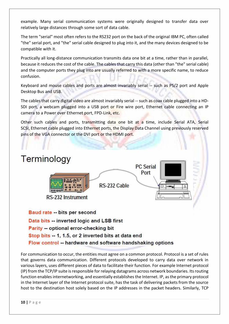
RS232:-
In telecommunications, RS-232 is a standard for serial communication transmission of data. It formally defines the signals connecting between a DTE (data terminal equipment) such as a computer terminal, and a DCE (data circuit-terminating equipment, originally defined as data communication equipment), such as a modem. The RS-232 standard is commonly used in computer serial ports. The standard defines the electrical characteristics and timing of signals, the meaning of signals, and the physical size and pin out of connectors. The current version of the standard is TIA-232-F Interface between Data Terminal Equipment and Data Circuit-Terminating Equipment Employing Serial Binary Data Interchange, issued in 1997. An RS-232 serial port was once a standard feature of a personal computer, used for connections to modems, printers, mice, data storage, uninterruptible power supplies, and other peripheral devices. However, RS-232 is hampered by low transmission speed, large voltage swing, and large standard connectors. In modern personal computers, USB has displaced RS-232 from most of its peripheral interface roles. Many computers do not come equipped with RS-232 ports and must use either an external USB-to-RS-232 converter or an internal expansion card with one or more serial ports to connect to RS-232 peripherals. RS-232 devices are still found, especially in industrial machines, networking equipment, and scientific instruments. In the case of RS-232 (A serial communication port standard), that's done this way: 1. Both side of the cable agree in advance on the communication parameters (speed, format...). That's done manually before communication starts. 2. The transmitter sends "idle" (="1") when and as long as the line is idle. 3. The transmitter sends "start" (="0") before each byte transmitted, so that the receiver can figure out that a byte is coming. 4. The 8 bits of the byte data are sent.
5. The transmitter sends "stop" (="1") after each byte.

14 | P a g e
The bits transitions are harder to see. That illustrates how important it is for the receiver to know at which speed the data is sent. The speed is specified in baud, i.e. how many bits-per-seconds can be sent.
LAN:-
A local-area network (LAN) is a computer network that spans a relatively small area. Most LANs are confined to a single building or group of buildings, however, one LAN can be connected to other LANs over any distance via telephone lines and radio waves. A system of LANs connected in this way is called a wide-area network (WAN). Most LANs connect workstations and personal computers. Each node (individual computer) in a LAN has its own CPU with which it executes programs, but it also is able to access data and devices
anywhere on the LAN. This means that many users can share expensive devices, such as laser printers, as well as data. Users can also use the LAN to communicate with each other, by sending e-mail or engaging in chat sessions. LANs are capable of transmitting data at very fast rates, much faster than data can be transmitted over a telephone line; but the distances are limited, and there is also a limit on the number of computers that can be attached to a single LAN. The following characteristics differentiate one LAN from another:
Topology: The geometric arrangement of devices on the network. For example, devices can be arranged in a ring or in a straight line.
Protocols: The rules and encoding specifications for sending data. The protocols also determine whether the network uses a peer-to-peer or client/server architecture.
Media: Devices can be connected by twisted-pair wire, coaxial cables, or fiber optic cables. Some networks do without connecting media altogether, communicating instead via radio waves.
WAN:-
A computer network that spans a relatively large geographical area. Typically, a WAN consists of two
or more local-area networks (LANs).

15 | P a g e
Computers connected to a wide-area network are often connected through public networks, such as
the telephone system. They can also be connected through leased lines or satellites. The largest WAN
in existence is the Internet.
A wide area network (WAN) is a network that covers a broad area (i.e., any telecommunications
network that links across metropolitan, regional, national or international boundaries) using leased
telecommunication lines. Business and government entities utilize WANs to relay data among
employees, clients, buyers, and suppliers from various geographical locations. In essence, this mode
of telecommunication allows a business to effectively carry out its daily function regardless of
location. The Internet can be considered a WAN as well, and is used by businesses, governments,
organizations, and individuals for almost any purpose imaginable.
EHTERNET:-
Ethernet is a family of computer networking technologies for local area networks (LANs). Ethernet
was commercially introduced in 1980 and standardized in 1983 as IEEE 802.3.Ethernet has largely
replaced competing wired LAN technologies such as token ring, FDDI, and ARCNET.
The Ethernet standards comprise several wiring and signaling variants of the OSI physical layer in
use with Ethernet. The original 10BASE5 Ethernet used coaxial cable as a shared medium. Later the
coaxial cables were replaced with twisted pair and fiber optic links in conjunction with hubs or
switches. Data rates were periodically increased from the original 10 megabits per second to 100
gigabits per second.
Systems communicating over Ethernet divide a stream of data into shorter pieces called frames.
Each frame contains source and destination addresses and error-checking data so that damaged
data can be detected and re-transmitted. As per the OSI model, Ethernet provides services up to
and including the data link layer.
16 | P a g e
Since its commercial release, Ethernet has retained a good degree of compatibility. Features such
as the 48-bit MAC address and Ethernet frame format have influenced other networking protocols.
NETWORK TIME PROTOCOL:-
Network Time Protocol (NTP) is a networking protocol for clock synchronization between
computer systems over packet-switched, variable-latency data networks.NTP is intended to
synchronize all participating computers to within a few milliseconds of Coordinated Universal Time
(UTC).It uses a modified version of Marzullo's algorithm to select accurate time servers and is
designed to mitigate the effects of variable network latency. NTP can usually maintain time to
within tens of milliseconds over the public Internet, and can achieve better than one millisecond
accuracy in local area networks under ideal conditions. Asymmetric routes and network congestion
can cause errors of 100 ms or more.
The protocol is usually described in terms of a client-server model, but can as easily be used in
peer-to-peer relationships where both peers consider the other to be a potential time source.[1]:20
Implementations send and receive timestamps using the User Datagram Protocol (UDP) on port
number 123.They can also use broadcasting or multicasting, where clients passively listen to time
updates after an initial round-trip calibrating exchange.[3] NTP supplies a warning of any impending
leap second adjustment, but no information about local time zones or daylight saving time is
transmitted.
As of June 2010, the current protocol is version 4 (NTPv4), which is a proposed standard as
documented in RFC 5905. It is backward compatible with version 3, specified in RFC 1305.
PRECISION TIME PROTOCOL:-
The Precision Time Protocol (PTP) is a protocol used to synchronize clocks throughout a computer
network. On a local area network, it achieves clock accuracy in the sub-microsecond range, making
it suitable for measurement and control systems.
PTP was originally defined in the IEEE 1588-2002 standard, officially entitled "Standard for a Precision
Clock Synchronization Protocol for Networked Measurement and Control Systems" and published in
2002. In 2008 a revised standard, IEEE 1588-2008 was released. This new version, also known as PTP
Version 2, improves accuracy, precision and robustness but is not backwards compatible with the
original 2002 version.
The IEEE 1588 standards describe a hierarchical master-slave architecture for clock distribution.
Under this architecture, a time distribution system consists of one or more communication media
(network segments), and one or more clocks. An ordinary clock is a device with a single network
connection and is either the source of (master) or destination for (slave) a synchronization reference.
A boundary clock has multiple network connections and can accurately bridge synchronization from

17 | P a g e
one network segment to another. A synchronization master is selected for each of the network
segments in the system. The root timing reference is called the grandmaster. The grandmaster
transmits synchronization information to the clocks residing on its network segment. The boundary
clocks with a presence on that segment then relay accurate time to the other segments to which they
are also connected.
LOGIC:-
The Hyper Terminal data is retrieved from the CTDU (Central Time division unit) located in the Central
Timing Room of Integrated Test Range DRDO Chandipur Lab. We can see the countdown time set for
an event in the Lab View front panel using the VISA configure, read write and close port. The software
module that has been designed, consists of a while loop which carries out its every subsequent
iteration after a 1 second delay using the Wait Until Next ms Multiple Function. The while loop
Repeats the sub-diagram inside it until the conditional terminal, an input terminal, receives a
particular Boolean value which depends on the continuation behaviour of the while loop.
The serial port specified by the VISA resource name was initialized through the VISA Configure Serial
Port VI. The data received from the CTDU after entering into the loop structure was first passed
through The Property Node which automatically adapts to the class of the object that is being
referenced. The output of the property node was then passed through the VISA Read Function which
reads the specified number of bytes from the device or interface specified by VISA resource name
and returns the data in read buffer.
The data is in form of string. It contains a lot of unnecessary characters which are not required, so
this has to be manipulated to obtain the useful data. The pattern after which the junk data comes is
identified by the following procedure. All characters after “\01” were extracted into one string using
a Match pattern function. Similarly all characters before “\r” were extracted using another Match
Pattern Function. The ‘after string’ of the first Match Pattern Function and ‘before string’ of the
second Match Pattern Function was concatenated as shown. This extracted data is manipulated to
get the required useful data.
The loop timer value is set to 1second which means the software gets data from HyperTerminal after
an interval of each second. The hour, second and minute are extracted from the final string and are
multiplied with the corresponding factors to obtain the total number of seconds is calculated.
However there is a delay in reading the data because the data from CTDU shows D which means
down. A case structure is implemented for the same. If there is a delay then one second is added, in
case there is advancement then a second is deducted, else it is kept as it is. It is the H, D, U structure.
Then the individual hour, minute, seconds are retrieved and the three numerical outputs
representing hour, minute and second was converted to their corresponding decimal strings using a
number to decimal string converter. The individual strings were then properly padded. The hour and
minute strings were concatenated with a ‘0’ before the string and ‘:’ after the string whereas the
seconds string was just concatenated with a ‘0’ before the string. The last three letters of the hour
and minute string; and the last two letters of the second string were extracted using substring
extraction. The three substrings were concatenated to get the output in the format of “HH:MM:SS”.
18 | P a g e
So the final string that will be transmitted to the client PC is ready. The UDP open function is used to
build a connection, the write function gets the data calculated above and the client PC address is fed
into it and hence the data is transmitted to that specific PC via Unicast method. The same data is fed
into the multicast connection where the connection socket is established by the Multicast open
function, the write function writes it, the Client PC address and the multicast address is fed into the
connection at respective locations. The close function closes the connection after the procedure is
over. The server PC has the VI for reception of data from the client PC. The UDP receiver circuit has
the same port number as addressed in the circuit for transmission (61556 in this case). The UDP open,
read and close functions are used to Open UDP port, read data from it, display and then closes the
connection. The same procedure is followed in multicast except for the block- where multicast
read/write open is used and the multicast address 224.1.1.1 is fed into both the sender and receiver
circuit. This is a class D IPv4 addressing. The data received is seen on the indicators respectively.
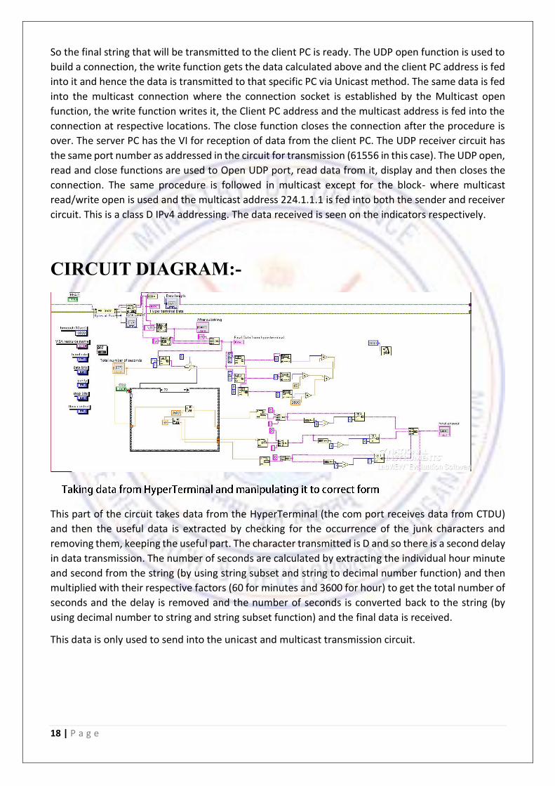
CIRCUIT DIAGRAM:-
This part of the circuit takes data from the HyperTerminal (the com port receives data from CTDU)
and then the useful data is extracted by checking for the occurrence of the junk characters and
removing them, keeping the useful part. The character transmitted is D and so there is a second delay
in data transmission. The number of seconds are calculated by extracting the individual hour minute
and second from the string (by using string subset and string to decimal number function) and then
multiplied with their respective factors (60 for minutes and 3600 for hour) to get the total number of
seconds and the delay is removed and the number of seconds is converted back to the string (by
using decimal number to string and string subset function) and the final data is received.
This data is only used to send into the unicast and multicast transmission circuit.

19 | P a g e
In this circuit the first part is unicast and the second one is multicast. The final data received in the
above part is fed into the UDP write blocks. The UDP open block establishes a connection for the
data transmission. The client PC address, the port number is fed into the write block. The receiver
circuit in the client PC should have the same port number as the server PC as that will complete the
connection. We can see the same data on the client and server PC screens.
The multicast connection is opened by the UDP multicast open block where the multicast address
(IPv4 Class D) is fed into string to IP function that creates the multicast connection. The write block
has the port number and client PC address fed into it which establishes the connection and same
data is seen on the server and client screen.
The multicast block here has three options: read only, write only, read and write. We have selected
read only because this is a sender circuit and we just need to read the data as of now after it is
received by the receiver circuit.
20 | P a g e
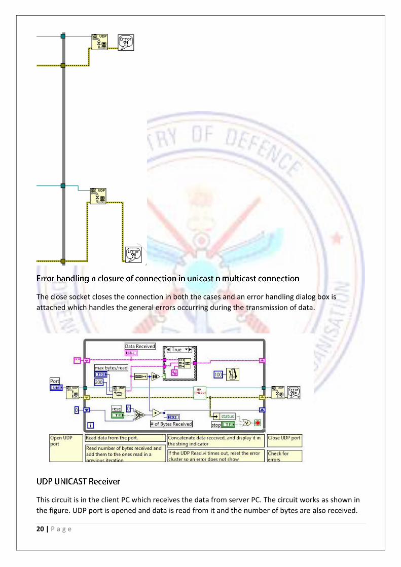
The close socket closes the connection in both the cases and an error handling dialog box is
attached which handles the general errors occurring during the transmission of data.
This circuit is in the client PC which receives the data from server PC. The circuit works as shown in
the figure. UDP port is opened and data is read from it and the number of bytes are also received.
21 | P a g e
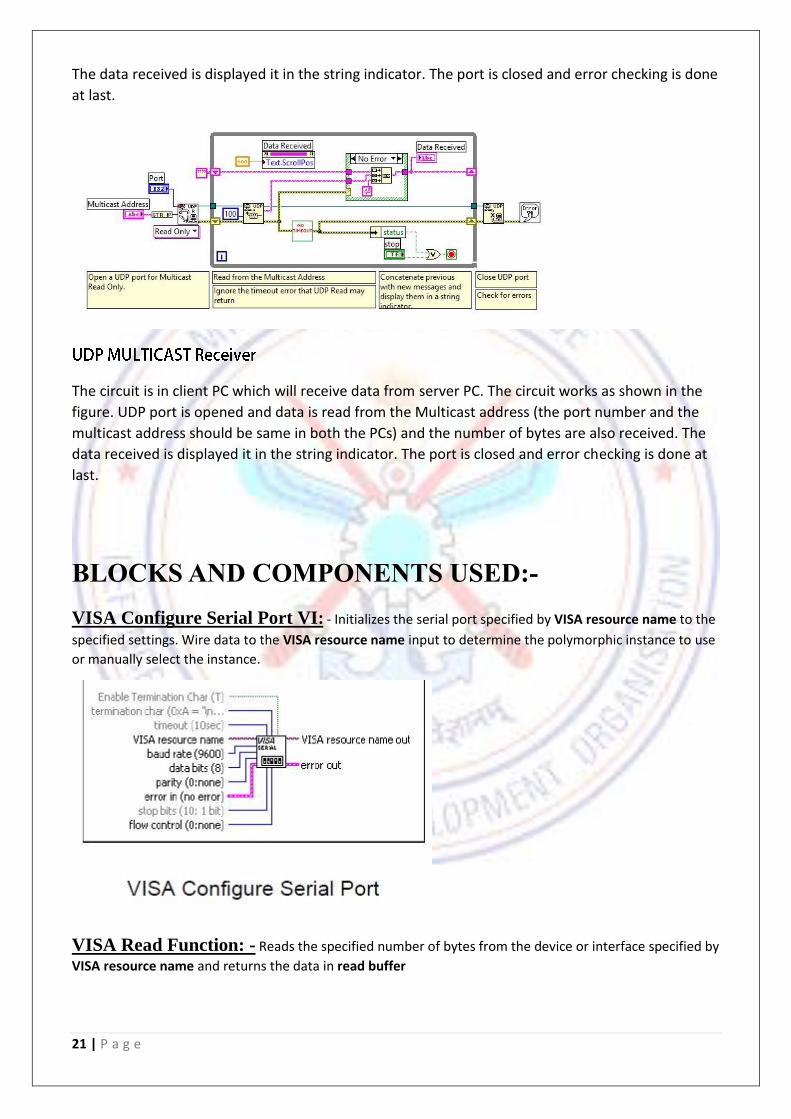
The data received is displayed it in the string indicator. The port is closed and error checking is done
at last.
The circuit is in client PC which will receive data from server PC. The circuit works as shown in the
figure. UDP port is opened and data is read from the Multicast address (the port number and the
multicast address should be same in both the PCs) and the number of bytes are also received. The
data received is displayed it in the string indicator. The port is closed and error checking is done at
last.
BLOCKS AND COMPONENTS USED:-
VISA Configure Serial Port VI: - Initializes the serial port specified by VISA resource name to the
specified settings. Wire data to the VISA resource name input to determine the polymorphic instance to use
or manually select the instance.
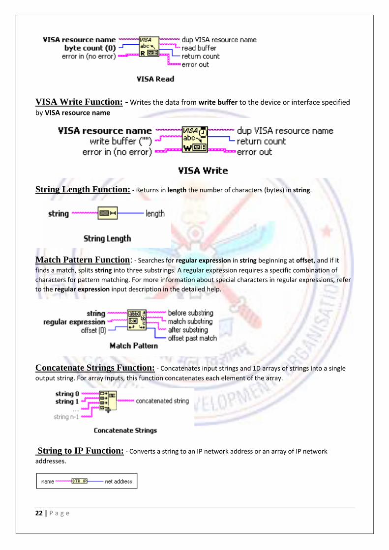
VISA Read Function: - Reads the specified number of bytes from the device or interface specified by
VISA resource name and returns the data in read buffer
22 | P a g e
VISA Write Function: - Writes the data from write buffer to the device or interface specified
by VISA resource name
String Length Function: - Returns in length the number of characters (bytes) in string.
Match Pattern Function: - Searches for regular expression in string beginning at offset, and if it
finds a match, splits string into three substrings. A regular expression requires a specific combination of
characters for pattern matching. For more information about special characters in regular expressions, refer
to the regular expression input description in the detailed help.
Concatenate Strings Function: - Concatenates input strings and 1D arrays of strings into a single
output string. For array inputs, this function concatenates each element of the array.
String to IP Function: - Converts a string to an IP network address or an array of IP network
addresses.
23 | P a g e
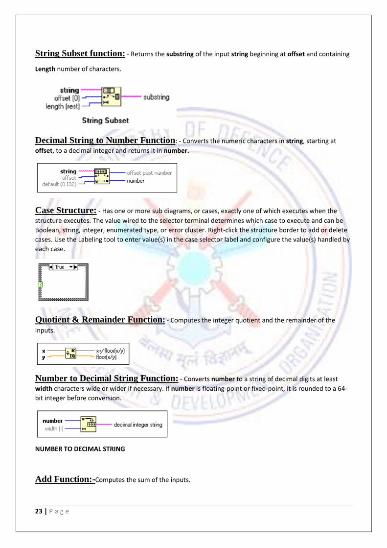
String Subset function: - Returns the substring of the input string beginning at offset and containing
Length number of characters.
Decimal String to Number Function: - Converts the numeric characters in string, starting at
offset, to a decimal integer and returns it in number.
Case Structure: - Has one or more sub diagrams, or cases, exactly one of which executes when the
structure executes. The value wired to the selector terminal determines which case to execute and can be
Boolean, string, integer, enumerated type, or error cluster. Right-click the structure border to add or delete
cases. Use the Labeling tool to enter value(s) in the case selector label and configure the value(s) handled by
each case.
Quotient & Remainder Function: - Computes the integer quotient and the remainder of the
inputs.
Number to Decimal String Function: - Converts number to a string of decimal digits at least
width characters wide or wider if necessary. If number is floating-point or fixed-point, it is rounded to a 64-
bit integer before conversion.
NUMBER TO DECIMAL STRING
Add Function:-Computes the sum of the inputs.

24 | P a g e
Multiply Function: - Returns the product of the inputs.
UDP Open Function: - Opens a UDP socket on the port or service name.
UDP open
UDP Read Function: - Reads a datagram from a UDP socket, returning the results in data out. The function returns data when it receives any bytes, and waits the full timeout ms only if it receives no bytes.
UDP Write Function: - Writes to a remote UDP socket.
UDP Close Function: - Closes a UDP socket.
UDP Multicast Open VI: - Opens a UDP multicast socket on the port.
25 | P a g e
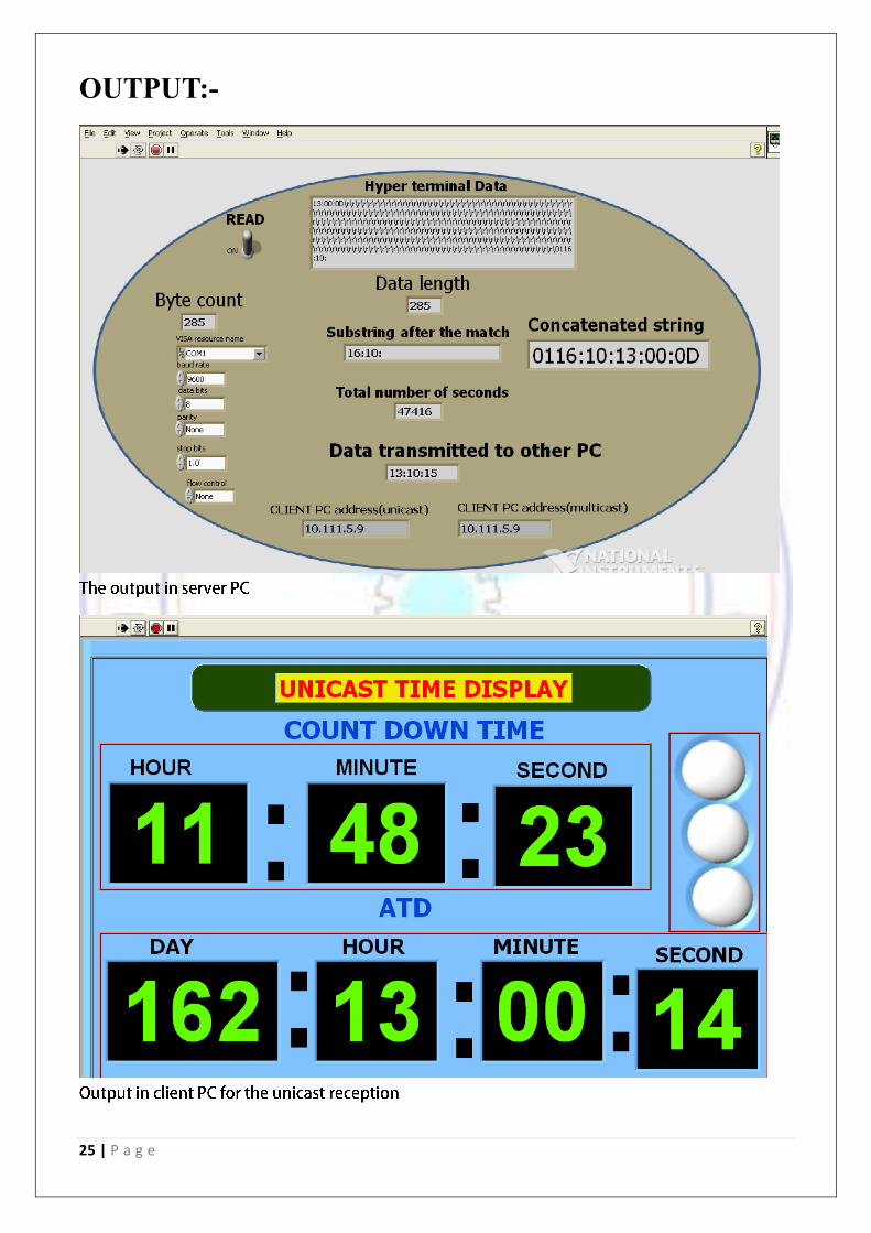
OUTPUT:-

26 | P a g e
APPLICATIONS:-
Modern day electronic systems such as communication, data handling, and missile and spacecraft
tracking systems require time-of-day and year information for correlation of data with time. Serial
formatted time codes are used to efficiently interface the timing system output with the user system.
Standardization of time codes is necessary to ensure system compatibility among the various ranges,
ground tracking networks, spacecraft and missile projects, data reduction facilities, and international
cooperative projects. These digital codes are typically amplitude modulated on an audio sine wave
carrier or transmitted as fast rise-time TTL signals.
Tracking security breaches, network usage, or problems affecting a large number of components can be nearly impossible if timestamps in logs are inaccurate. Time is often the critical factor that allows an event on one network node to be mapped to a corresponding event on another.
To reduce confusion in shared file systems, it is important for the modification times to be consistent, regardless of what machine the file systems are on.
Billing services and similar applications must know the time accurately. Some financial services require highly accurate timekeeping by law. Sarbanes-Oxley and HIPAA Security Rules both require accurate time stamping.

27 | P a g e
Time Synchronization in wireless networks is extremely important for basic communication, but it
also provides the ability to detect movement, location, and proximity. Countdown Time is commonly
used in detonation of an explosive, Rocket and missile launching spacecraft tracking systems etc.
CONCLUSION:-
Lab View is a very interactive and user-friendly software where lots of circuits can be implemented
in a very simple manner. This project gave a vivid idea of how to use the software in a best possible
way as a beginner and covering lots of theoretical topics while implementing the same helped in
understanding lots of concepts better. The problems faced and trying to solve them in the efficient
way possible and visualizing the theoretical concepts while making the circuit and their realization
was surely a great experience. The data was received from the HyperTerminal and manipulated into
the required form and then sent to the client PC from the server PC using the mentioned software.
The countdown time from the centralized time division unit which works on PTP protocol was used
as the data. Many things about networks and data transmission was covered in this project and
coming across new was surely a great experience. The software has a wide range of application as
explained above and can be extended as needed.

28 | P a g e
REFERENCES
[1] Communications and Networking by William Stallings.
[2] Data Communications By Forouzan
[3] "www.ni.com," [Online].
[4] "Wikipedia," [Online].


![FINAL PROJECT REPORT1[1]](https://img.dokumen.tips/doc/110x75/549e4753b37959af618b4682/final-project-report11.jpg)