Embed Size (px)
Citation preview

DRAINAGE STRUCTURES 03D
MUNICIPAL INFRASTRUCTURE TECHNICAL SPECIFICATION 03 - UNDERGROUND SERVICES
Transport Canberra and City Services
July 2019

ACT Government 2
Publication Number: MITS 03D Edition 1 Revision 0
Date of Effect: July 2019
Supersedes: Standard Specification for Urban Infrastructure Works Section 03 Edition 1 Revision 0 September 2002
Endorsed By: Karl Cloos Director, Infrastructure Planning
Approved By: Ken Marshall Executive Branch Manager, Roads ACT
Document Information
Document Key Information
Document Title MITS 03D Drainage Structures
Next review date
Key words
AUS-SPEC Base Document 1354 Drainage structures
Revision Register
Edition/ Revision Number Clause Number Description of Revision Authorised By Date
1/0

ACT Government 3
CONTENTS
1 DRAINAGE STRUCTURES ........................................................................... 4
1.1 General ........................................................................................................................ 4
1.1.1 Responsibilities ....................................................................................................................... 4 1.1.2 Cross references ..................................................................................................................... 4 1.1.3 Referenced documents .......................................................................................................... 4 1.1.4 Interpretation ......................................................................................................................... 5 1.1.5 Hold points and witness points .............................................................................................. 6
1.2 Materials ...................................................................................................................... 7
1.2.1 Constituent materials ............................................................................................................. 7 1.2.2 Precast units ........................................................................................................................... 7
1.3 Execution ..................................................................................................................... 8
1.3.1 Provision for traffic ................................................................................................................. 8 1.3.2 Site establishment .................................................................................................................. 8 1.3.3 Excavation .............................................................................................................................. 8 1.3.4 Installation .............................................................................................................................. 8 1.3.5 Headwalls and wingwalls ....................................................................................................... 9 1.3.6 Sumps and manholes ............................................................................................................. 9 1.3.7 Other structures ................................................................................................................... 11 1.3.8 Backfill .................................................................................................................................. 11
1.4 Completion ................................................................................................................ 12
2 MEASUREMENT AND PAYMENT .............................................................. 13
2.1 Measurement ............................................................................................................ 13
2.2 Pay items ................................................................................................................... 14
LIST OF TABLES
Table 3D-1 Hold point table...................................................................................................................... 6 Table 3D-2 Witness point table ................................................................................................................ 6 Table 3D-3 Pay items table ..................................................................................................................... 14

ACT Government 4
1 DRAINAGE STRUCTURES 1.1 General 1.1.1 Responsibilities
1.1.1.1 General Requirement: Provide drainage structures as documented including the following: Headwalls, wingwalls, pits, gully pits, inspection pits, sealed sumps, drop structures, inlet and outlet structures, energy dissipators, batter drains and other supplementary structures as shown on the drawings.
1.1.2 Cross references General: The following documents are related to this Specification.
1.1.2.1 ACT Legislation Road Transport (General) Act
Public Roads Act
Scaffolding and Lifts Act
Scaffolding and Lifts Regulation
Work Health and Safety Act
1.1.2.2 Specifications Requirement: Conform to the following:
MITS 00 Preliminaries
MITS 01 Traffic Management
MITS 02 Earthworks
MITS 04 Flexible pavement construction
MITS 06A Concrete kerbs & open drains
MITS 08 Incidental works
MITS 09 Landscape
MITS 10 Concrete works
MITS 16D Gross Pollutant Traps
1.1.3 Referenced documents
1.1.3.1 Standards General: The following documents are incorporated into this Specification by reference:
Australian standards
AS 1012 Methods of testing concrete
AS 1214 Hot-dip galvanized coatings on threaded fasteners
AS 1379 Specification and supply of concrete

ACT Government 5
AS 1478 Chemical admixtures for concrete, mortar and grout
AS 1478.1 Admixtures for concrete
AS/NZS 1554 Structural steel welding
AS/NZS 1554.3 Welding of reinforcing steel
AS 1657 Fixed platforms, walkways, stairways and ladders – Design, construction and installation
AS 1726 Geotechnical site investigations
AS 2758 Aggregates and rock for engineering purposes
AS 2758.1 Concrete aggregates
AS 3600 Concrete structures
AS 3610 Formwork for concrete
AS 3610.1 Documentation and surface finish
AS 3735 Concrete structures retaining liquids
AS 3972 General purpose and blended cements
AS 3996 Access covers and grates
AS/NZS 4671 Steel reinforcing materials
AS 4680 Hot-dip galvanized (zinc) coatings on fabricated ferrous articles
AS 5100 Bridge design
Austroads
AGPT Austroads Guide to Pavement Technology
AGPT04G Part 4G: Geotextiles and geogrids
1.1.3.2 Other publications Proprietary products: To TCCS Products previously considered for use list
1.1.4 Interpretation
1.1.4.1 Abbreviations GPT: Gross Pollutant Trap
MH: Maintenance hole
TCCS: Transport Canberra and City Services, ACT Government and its successors.
1.1.4.2 Definitions General: For the purpose of this Specification, the definitions of terms used to define the components of the road reserve are in conformance with AS 1348, Glossary of Austroads Terms and AGRD03, the definitions given below also apply:
Drainage structures: Devices to control stormwater flowing into and through a stormwater drainage system including culverts, inlet and outlet structures, sumps, manholes, drop structures, headwalls, wingwalls, energy dissipaters and ancillary hardware such as grates, frames and step irons as well as subsurface drainage pipes at pits, headwalls and wingwalls.

ACT Government 6
1.1.5 Hold points and witness points
1.1.5.1 Notice General: Give written notice to the Authorised Person so that the documented inspection and submissions may be made to the Hold point table and the Witness point table.
Table 3D-1 Hold point table
Item Clause title Requirement Notice for inspection
Release by
Materials
3D.1 Precast units - General
Submit details of precast or proprietary items for approval, including drawings, method of manufacture, testing and installation.
3 working days before ordering
Authorised Person
3D.2 Precast units - Substitutions
Submit details for substituting precast units for cast insitu units.
3 working days before ordering
Authorised Person
Execution
3D.3 Installation – Cast insitu reinforced concrete structures
Submit certification that installation of reinforcement and compliance of formwork conforms with MITS 10 Concrete works and the Drawings and give notice for inspection.
1 working day before pouring concrete
Authorised Person
Table 3D-2 Witness point table
Item Clause title Requirement Notice for inspection
Execution
3D.1 Sumps and manholes - Precast units Give notice of installation of precast sumps 1 week

ACT Government 7
1.2 Materials 1.2.1 Constituent materials
1.2.1.1 Concrete Concrete, reinforcement and formwork: To MITS 10 Concrete works.
Minimum grade: Unless noted otherwise, adopt the following:
> Manholes including covers: N32. > Scour stops, concrete bedding and encasement: N20.
Formwork: Both internal and external surfaces shall be formed. The Contractor may elect to omit external forms where surfaces are increased by 50mm thickness and cast against undisturbed ground. External formwork shall be used for the top 300mm of manholes and sumps in all cases.
1.2.1.2 Steel fixtures Mild steel fixtures: All mild steel fixtures including grates, frames, step irons, ladders etc., shall be hot dip galvanised to AS 1214 or AS 4680, as appropriate.
1.2.2 Precast units
1.2.2.1 General Product drawings: For any precast item, including proprietary items submit the following:
> Product (“shop”) drawings. > Method of manufacture, testing and installation including clearance to pit shaft ends, pipe to pipe
jointing and step iron positioning
This is a HOLD POINT.
1.2.2.2 Substitutions Substituting precast units for cast insitu units: Submit details including proposed methodology for approval.
This is a HOLD POINT.
1.2.2.3 Marking Identification marking: At the time of manufacture, clearly mark each precast unit with the following information:
> Date of manufacture. > Manufacturer’s name or registered mark and the location of manufacture. > Maximum mass of unit in kg. > Batch number. > Inspection status.
Height of letters: 75mm.
Location of marking: Easily visible but hidden once the unit is installed.

ACT Government 8
1.3 Execution 1.3.1 Provision for traffic
1.3.1.1 General Requirement: Conform to MITS 01 Traffic Management.
1.3.2 Site establishment
1.3.2.1 Survey Requirement: Conform to MITS 00 Preliminaries.
1.3.2.2 Handling, delivery and storage Handling and installation: Handle and install precast units, including kerb inlet lintels, to conform to the manufacturer’s instructions.
1.3.3 Excavation
1.3.3.1 General Excavation: Conform to MITS 03A Trenching for underground services and MITS 02B Bulk Earthworks.
Bedding, support and backfill material: Unless otherwise documented, to MITS 03A Trenching for underground services.
1.3.4 Installation
1.3.4.1 General Members subject to traffic and earth loads: To AS 5100 Series.
Water retaining structures with a capacity > 25,000 L: To AS 3735.
Water retaining structures with a capacity ≤ 25,000 L: To AS 3600.
Other concrete components: Conform to AS 3600.
Horizontal tolerance: ± 25mm.
Inlet and outlet invert levels: As shown on the drawings ± 10mm.
Benching: Bench bases as detailed and finish smoothly to minimise turbulent flow.
Render: Rendering of concrete structures shall not be permitted.
1.3.4.2 Foundation Preparation: Dewater and wash clean of contaminants in preparation for concreting.
1.3.4.3 Joints and seals Location: Provide isolation joints adjacent to drainage structure where they abut another structure or concrete pavement.
Isolation joint: 10mm wide approved preformed jointing filler.
Sealing: Effectively seal joints and connection points against the ingress of water and other kinds of material with cement mortar 1: 3 general purpose cement: sand ratio.

ACT Government 9
1.3.4.4 Cast insitu reinforced concrete structures Headwalls and wingwalls, special chambered manholes and special structures: Certify that the installation of reinforcement and compliance of formwork conforms with MITS 10 Concrete works and the Drawings. The placed reinforcement shall be inspected by the Authorised Person prior to the concrete being poured.
This is a HOLD POINT.
1.3.5 Headwalls and wingwalls
1.3.5.1 Alignment Arrangement: Unless otherwise shown on the drawings, construct headwalls and pits parallel to the road centreline and wingwalls at 135° to the headwall.
Skewness: If the culvert is laid skew to the road, splay the wingwalls and headwalls so that the front edge of the wing bisects the angle between the centreline of the culvert and the headwall.
1.3.5.2 Weepholes Detail: Provide weepholes as shown on the drawings.
Requirement: Place broken stone or river gravel to MITS 03A Trenching for underground services as follows:
> Height: > 450mm above the bottom of the weephole. > Plan area: > 600mm along the wall and 300mm out from the wall located centrally about the
weephole.
Geotextile: Enclose the broken stone or river gravel with geotextile filter fabric in conformance with AGPT04G.
Alternative to geotextile: Cover the facial area of the structure with an equivalent area of geocomposite.
1.3.6 Sumps and manholes
1.3.6.1 Construction Details: Construct all new manholes to accept access covers, gully grates and frames to AS 3996 and the Standard drawings.
Types:
> R sump > Grated sump Type 1 > Grated sump Type 2 > Single sided plantation sump > Double sided plantation sump > Double R sump > QS sump > On grade KI sump > Sag point KI sump
Standard Drawings: ACTSD-0820-0826.

ACT Government 10
Sealed sumps: Construct as for standard sumps without a kerb opening. The sump shall be setback behind the kerb.
Existing pits: Modify existing pits only if shown on the drawings. Where existing structures are to be raised or lowered, break out walls to expose reinforcement and allow a minimum of 150mm of new concrete below the new cover or frame. Splice new reinforcement to old, form and place concrete as specified for new structures.
1.3.6.2 Precast units Knockouts: Do not provide standard precast pit base units with thinned wall sections on all 4 sides. Provide base units and other riser units to suit the design configuration of the particular pit with preformed knockouts only where required.
Notice: Give notice before installation of precast sumps.
This is a WITNESS POINT.
Precast concrete manholes: Construct insitu concrete bases to match precast components. The minimum concrete thickness between the invert of the seating ring and the crown of the highest pipe shall be 25mm. This ring shall be filled with a 3:1 sand cement mortar prior to the placement of precast components and trowelled off after installation.
1.3.6.3 Access covers and frames Access cover: Locate so that removal of the cover is not obstructed by a wall, kerb or other fixed item.
Fit and seals may be compromised: Covers and frames are matched items. Do not switch. Ensure there is no excavated or other material between cover and frame to compromise seals and service life.
Proprietary access covers: Conform to the manufacturer’s recommendations, including any infill requirements for the covers.
Marking: All stormwater manholes shall be marked with the letters “SW”.
Grade: Provide Heavy Duty Class D covers and frames to AS 3996 with 600mm clear opening in paved or trafficable areas.
Levels: Cover levels are provided for guidance only. The Contractor is responsible for ensuring finished levels to the following:
> Paved areas: Finish flush with pavement. > Landscaped areas including verges: Finish 25mm above finished surface. > Other areas: Finished 75mm above finished surface.
1.3.6.4 Rung ladders and step irons Standard drawing: ACTSD-0830.
Structures > 900mm deep: Install an individual rung ladder or step iron on one internal wall for the full depth of the structure to conform to AS 1657.
ACT Government 11
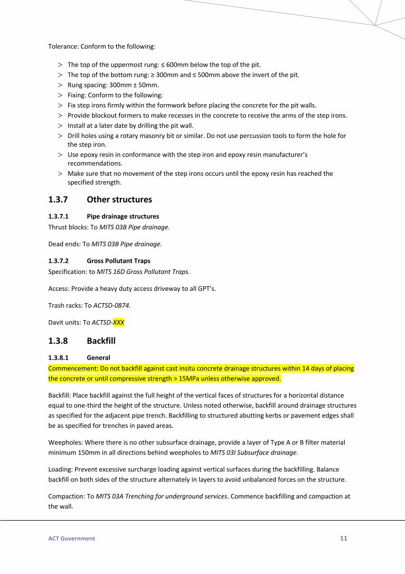
Tolerance: Conform to the following:
> The top of the uppermost rung: ≤ 600mm below the top of the pit. > The top of the bottom rung: ≥ 300mm and ≤ 500mm above the invert of the pit. > Rung spacing: 300mm ± 50mm. > Fixing: Conform to the following: > Fix step irons firmly within the formwork before placing the concrete for the pit walls. > Provide blockout formers to make recesses in the concrete to receive the arms of the step irons. > Install at a later date by drilling the pit wall. > Drill holes using a rotary masonry bit or similar. Do not use percussion tools to form the hole for
the step iron. > Use epoxy resin in conformance with the step iron and epoxy resin manufacturer’s
recommendations. > Make sure that no movement of the step irons occurs until the epoxy resin has reached the
specified strength.
1.3.7 Other structures
1.3.7.1 Pipe drainage structures Thrust blocks: To MITS 03B Pipe drainage.
Dead ends: To MITS 03B Pipe drainage.
1.3.7.2 Gross Pollutant Traps Specification: to MITS 16D Gross Pollutant Traps.
Access: Provide a heavy duty access driveway to all GPT’s.
Trash racks: To ACTSD-0874.
Davit units: To ACTSD-XXX
1.3.8 Backfill
1.3.8.1 General Commencement: Do not backfill against cast insitu concrete drainage structures within 14 days of placing the concrete or until compressive strength > 15MPa unless otherwise approved.
Backfill: Place backfill against the full height of the vertical faces of structures for a horizontal distance equal to one-third the height of the structure. Unless noted otherwise, backfill around drainage structures as specified for the adjacent pipe trench. Backfilling to structured abutting kerbs or pavement edges shall be as specified for trenches in paved areas.
Weepholes: Where there is no other subsurface drainage, provide a layer of Type A or B filter material minimum 150mm in all directions behind weepholes to MITS 03I Subsurface drainage.
Loading: Prevent excessive surcharge loading against vertical surfaces during the backfilling. Balance backfill on both sides of the structure alternately in layers to avoid unbalanced forces on the structure.
Compaction: To MITS 03A Trenching for underground services. Commence backfilling and compaction at the wall.

ACT Government 12
1.4 Completion 1.4.1.1 Submissions Work as Executed Records: To MITS 00B Quality Requirements.
1.4.1.2 CCTV for Stormwater Closed circuit television (CCTV) inspections: Submit a report to the Authorised Person for approval in accordance with TCCS Reference Document 8 Requirements for Work-As-Executed Quality Records requirements, including video evidence for all drainage structures as follows:
> On completion of all drainage structures and prior to commencement of pavement construction above the drainage structure to verify the works are within the specified tolerances and without visual signs of structural failure.
> No more than 14 days prior to Practical Completion to verify tolerances and ensure there is no obstruction to the flow of water.
Defects: Any defects identified by the CCTV inspection shall be rectified together with a new CCTV inspection report prior to requesting final inspection.
Repair: Repair of damaged pipes by patching is not acceptable.

ACT Government 13
2 MEASUREMENT AND PAYMENT 2.1 Measurement 2.1.1.1 General Payments made to the Bill of Quantities: To MITS 00A General requirements, this Specification, the drawings and Pay items.
2.1.1.2 Methodology The following methodology will be applied for measurement and payment:
> Allow for all work, materials, testing and quality assurance requirements in each Pay Item. > Excavation, bedding, support and backfill material for drainage structures: Conform to MITS 03A
Trenching for underground services, paid under this Specification. > Miscellaneous minor concrete work not included in the pay items in this Specification: To MITS 06
Concrete kerbs, footpaths and minor works. > Subsoil drains: To MITS 03J Subsoil and foundation drainage. > Thrust blocks and dead ends: To MITS 03B Pipe drainage. > Backfill under roads, paths and driveways: Extra over to MITS 03H Road openings and restorations. > Barrier fences for drainage structures: To MITS 08A Fences and Barriers. > Sealed sumps: Paid as standard sumps. > Removal of existing drainage structures: To MITS 03A Trenching for underground services. > Hardstand pavement, driveways, kerbing for GPT’s: To MITS 06A Concrete kerbs and open drains
and MITS 06B Concrete paths, driveways medians. > Drop structures: To MITS 06A Concrete kerbs and open drains. > Excavation and replacement of Unsuitable Material in Trenches: MITS 02B Bulk Earthworks. > All costs associated with removal of water from excavations shall be included within respective
excavation rates for drainage structures. > No Additional payment will be made for excavation in rock, overbreak of trench due to ground
conditions or over excavation of trenches.
2.1.1.3 Deductions Insitu concrete strength: Deductions made as follows:
> Scheduled rate of payment is reduced by 2% for each 1%, or fraction thereof, by which the strength of the specimen fails to reach the specified strength, up to a maximum deficiency of 10%.
> If the deficiency in strength exceeds 10%, the concrete represented by the specimens may be rejected, in which case no payment will be made.

ACT Government 14
2.2 Pay items Table 3D-3 Pay items table
Item No
Pay items Unit of measurement Schedule of rates scope
3D.1 Stormwater MH
Number All activities associated with construction of 1050mm diameter stormwater maintenance holes including excavation in all types of material encountered including rock, over excavation for bedding, shoring, supply and placement of bedding, concrete, reinforcement, formwork, precast units, step irons, precast cone and Class B access cover. This pay item shall include benching, sealing, marking, backfilling and compaction around the structure.
3D.2 Stormwater MH >1.45m
Total depth in metres Measured as additional depth per MH to nearest 100mm
All activities extra over Stormwater MH associated with construction of 1050mm diameter maintenance holes deeper than 1.45m measured from the top of the cover to the underside of the base.
3D.3 Class D access covers
Number All activities extra over Stormwater MH associated with supply and installation of Class D access covers for 1050mm diameter maintenance holes.
3D.4 Special chambered MH
Number All activities associated with construction of special chambered stormwater maintenance holes including excavation in all types of material encountered including rock, over excavation for bedding, shoring, supply and placement of bedding, concrete, reinforcement, formwork, step irons, access shaft, precast cone and Class D access cover. This pay item shall include benching, sealing, marking, backfilling and compaction around the structure. A separate pay item shall be included in the Contract for each special chambered manhole. For example;
3D.4.1 Special chambered MH 1/1 3D.4.2 Special chambered MH 1/2 Etc...

ACT Government 15
Item No
Pay items Unit of measurement Schedule of rates scope
3D.5 Stormwater sumps
Number All activities associated with construction of stormwater sumps including excavation in all types of material encountered including rock, over excavation for bedding, shoring, supply and placement of bedding, concrete, reinforcement, formwork, precast units, step irons, Class D grate and surround, precast lid and Class B access cover, as detailed. This pay item shall include benching, sealing, concrete aprons, matching to kerb line, backfilling and compaction around the structure. A separate pay item shall be included in the Contract for each type of stormwater sump.
3D.5.1 R sump 3D.5.2 Grated sump Type 1 3D.5.3 Grated sump Type 2 3D.5.4 Single sided plantation sump 3D.5.5 Double sided plantation sump 3D.5.6 Double R sump 3D.5.7 QS sump 3D.5.8 On grade KI sump 3D.5.9 Sag point KI sump
3D.6 Stormwater sumps >1.8m
Total depth in metres Measured as additional depth per sump to nearest 100mm
All activities extra over Stormwater sumps associated with construction of sumps deeper than 1.8m measured from the top of the cover to the underside of the base. A separate pay item shall be included in the Contract for each type of stormwater sump.
3D.6.1 R sump 3D.6.2 Grated sump Type 1 3D.6.3 Grated sump Type 2 3D.6.4 Single sided plantation sump 3D.6.5 Double sided plantation sump 3D.6.6 Double R sump

ACT Government 16
Item No
Pay items Unit of measurement Schedule of rates scope
3D.7 Surcharge structures
Number All activities associated with construction of surcharge structures including excavation in all types of material encountered including rock, over excavation for bedding, shoring, supply and placement of bedding, concrete, reinforcement, formwork, precast units, step irons, Class D grate and surround, as detailed. This pay item shall include benching, sealing, concrete aprons, backfilling and compaction around the structure. A separate pay item shall be included in the Contract for each surcharge structure. For example;
3D.7.1 Surcharge structure 1/1 3D.7.2 Surcharge structure 1/2
Etc...
3D.8 Headwalls Number All activities associated with the construction of headwalls and associated footings including excavation for the units in all types of material encountered including rock, shoring, supply and placement of bedding, concrete, reinforcement, formwork, weepholes, filter material and precast walls. This pay item shall include jointing, sealing, backfilling and compaction around the structure. A separate pay item shall be included in the Contract for each headwall type including a description of the overall culvert dimensions. For example;
3D.8.1 Culvert 1: 900Wx450H headwall 3D.8.2 Pipe Culvert 1/1-1/2: DN450 headwall
Etc...

Transport Canberra and City Services
July 2019