Embed Size (px)
Citation preview

DRAFT SOUTH AFRICAN STANDARD (DSS):
PUBLIC ENQUIRY STAGE
Document number SANS 10160-6
Reference 7114/10160-6/DL
Date of circulation 2009-10-13
Closing date 2009-12-15
Number and title: SANS 10160-6: BASIS OF STRUCTURAL DESIGN AND ACTIONS FOR BUILDINGS AND INDUSTRIAL STRUCTURES — PART 6: ACTIONS INDUCED BY CRANES AND MACHINERY Remarks:
PLEASE NOTE:
• The technical committee, SABS SC 59I responsible for the preparation of this standard has reached consensus that the attached document should become a South African standard. It is now made available by way of public enquiry to all interested and affected parties for public comment, and to the technical committee members for record purposes. Any comments should be sent by the indicated closing date, either by mail, or by fax, or by e-mail to
SABS Standards Division Attention: Compliance and Development department Private Bag X191 Pretoria 0001 Fax No.: (012) 344-1568 (for attention: dsscomments) E-mail: [email protected]
Any comment on the draft must contain in its heading the number of the clause/subclause to which it refers. A comment shall be well motivated and, where applicable, contain the proposed amended text.
• The public enquiry stage will be repeated if the technical committee agrees to significant technical
changes to the document as a result of public comment. Less urgent technical comments will be considered at the time of the next amendment.
THIS DOCUMENT IS A DRAFT CIRCULATED FOR PUBLIC COMMENT. IT MAY NOT BE REFERRED TO AS A
SOUTH AFRICAN STANDARD UNTIL PUBLISHED AS SUCH.
IN ADDITION TO THEIR EVALUATION AS BEING ACCEPTABLE FOR INDUSTRIAL, TECHNOLOGICAL,
COMMERCIAL AND USER PURPOSES, DRAFT SOUTH AFRICAN STANDARDS MAY ON OCCASION HAVE TO BE CONSIDERED IN THE LIGHT OF THEIR POTENTIAL TO BECOME STANDARDS TO WHICH REFERENCE MAY BE MADE IN LAW.
AZ96.10 2008/08/08 sabs pta
This standard is a draft South African National Standard and is made available for commenting purposes only. It may not be resold. Contact the South African Bureau of Standards (tel. 012 428-6666, email. [email protected]) for more information on their copyright rules.

ISBN 978-0-626- SANS 10160-6:2009Edition 1
SOUTH AFRICAN NATIONAL STANDARD
Basis of structural design and actions for buildings and industrial structures Part 6: Actions induced by cranes and machinery
Published by SABS Standards Division 1 Dr Lategan Road Groenkloof Private Bag X191 Pretoria 0001 Tel: +27 12 428 7911 Fax: +27 12 344 1568 www.sabs.co.za © SABS
This standard is a draft South African National Standard and is made available for commenting purposes only. It may not be resold. Contact the South African Bureau of Standards (tel. 012 428-6666, email. [email protected]) for more information on their copyright rules.

SANS 10160-6:2009 Edition 1 Table of changes Change No. Date Scope
Foreword This South African standard was approved by National Committee SABS SC 59I, Construction standards – Basis for the design of structures, in accordance with procedures of the SABS Standards Division, in compliance with annex 3 of the WTO/TBT agreement. This edition cancels and replaces the second edition (SABS 0160:1989). SANS 10160 consists of the following eight parts, under the general title Basis of structural design and actions for buildings and industrial structures: SANS 10160-1, Basis of structural design SANS 10160-2, Self-weight and imposed loads SANS 10160-3, Wind actions SANS 10160-4, Seismic actions and general requirements for buildings SANS 10160-5, Basis of geotechnical design and actions SANS 10160-6, Actions induced by cranes and machinery SANS 10160-7, Thermal actions SANS 10160-8, Actions during execution
This standard is a draft South African National Standard and is made available for commenting purposes only. It may not be resold. Contact the South African Bureau of Standards (tel. 012 428-6666, email. [email protected]) for more information on their copyright rules.

SANS 10160-6:2009 Edition 1
1
Contents
Page Foreword 1 Scope ...................................................................................................................................... 2 Normative references.............................................................................................................. 3 Definitions and symbols ........................................................................................................ 4 Actions induced hoists and cranes on runway beams ............................................................ 4.1 Field of application ....................................................................................................... 4.2 Classification of actions ................................................................................................ 4.3 Design situations ........................................................................................................... 4.4 Representation of crane actions .................................................................................... 4.5 Load arrangements ........................................................................................................ 4.6 Vertical crane loads-characteristic values ..................................................................... 4.7 Horizontal crane loads-characteristic value .................................................................. 4.8 Environmental effects ................................................................................................... 4.9 Loads on access walkways, stairs, platforms and guard rails ....................................... 4.10 Test loads ...................................................................................................................... 4.11 Fatigue loads ................................................................................................................. 4.12 Accidental actions ......................................................................................................... 5 Limit states design verification .............................................................................................. 5.1 Combination values for crane induced actions ............................................................. 5.2 Crane induced actions for the ultimate state ................................................................. 5.3 Crane induced actions for the serviceability limit state ................................................ 6 Actions induced by machinery .............................................................................................. 6.1 Field of application ....................................................................................................... 6.2 Classification of actions ................................................................................................ 6.3 Design situations ........................................................................................................... 6.4 Representation of actions .............................................................................................. 6.5 Special considerations ................................................................................................... 6.6 Characteristic values ..................................................................................................... 6.7 Serviceability ctriteria ................................................................................................... Annex A (informative) Guidance for crane classification ......................................................... Annex B (informative) Example of a model for estimating the value of the dynamic actor 4φ for a crane travelling on rails ................................................................................... Annex C (informative) Guidance for serviceability design criteria ...........................................
This standard is a draft South African National Standard and is made available for commenting purposes only. It may not be resold. Contact the South African Bureau of Standards (tel. 012 428-6666, email. [email protected]) for more information on their copyright rules.

SANS 10160-6:2009 Edition 1
2
This page is intentionally left blank
This standard is a draft South African National Standard and is made available for commenting purposes only. It may not be resold. Contact the South African Bureau of Standards (tel. 012 428-6666, email. [email protected]) for more information on their copyright rules.

SANS 10160-6:2009 Edition 1
3
Basis of structural design and actions for buildings and industrial structures Part 6: Actions induced by cranes and machinery 1 SCOPE This Part of the Standard specifies imposed loads associated with overhead travelling bridge cranes on runway beams at the same level as well as the actions induced by stationary machinery. 2 NORMATIVE REFERENCES The following referenced documents are indispensable for the application of this document. All normative documents are subject to revision and, since any reference to a normative document is deemed to be reference to the latest edition of that document, parties to agreement based on this document are encouraged to take steps to ensure the use of the most recent editions of the normative documents indicated below. Information on currently valid national and international standards can be obtained from Standards South Africa. SANS 10100-1; The structural use of concrete Part 1: Design SANS 10137; The installation of glazing in buildings SANS 10160-1; Basis of structural design SANS 10160-2; Self-weight and imposed loads SANS 10160-3; Wind actions SANS 10160-4; Seismic actions and general requirements for buildings SANS 10160-5; Basis for geotechnical design and actions SANS 10160-7; Thermal actions SANS 10160-8; Actions during execution SANS 10162-1; The structural use of steel Part 1: Limit-state design of hot-rolled steelwork
This standard is a draft South African National Standard and is made available for commenting purposes only. It may not be resold. Contact the South African Bureau of Standards (tel. 012 428-6666, email. [email protected]) for more information on their copyright rules.
SANS 10160-6:2009 Edition 1
4
SANS 10162-2; The structural use of steel Part 2: Limit-states design of cold-formed steelwork SANS 10162-4; Structural use of steel Part 4: The design of cold-formed stainless steel structural members SANS 10163-1; The structural use of timber Part 1: Limit-states design SANS 10164-2; The structural use of masonry Part 2: Structural design and requirements for reinforced and pre-stressed masonry ISO 3898 3 Definitions and symbols 3.1 Definitions 3.1.1 Terms and definitions specifically hoists and cranes on runway girders 3.1.1.1 dynamic factor factor that represents the ratio of the dynamic response to the static response. 3.1.1.2 self-weight cQ of the crane the self-weight of all fixed and movable elements including the mechanical and electrical equipment of the crane structure, however without the lifting attachment and a portion of the suspended hoist ropes or chains moved by the crane structure. 3.1.1.3 hoist load hQ the hoist load includes the masses of the payload, lifting attachment and a portion of the suspended hoist ropes or chains moved by the crane structure 3.1.1.4 crab part of an overhead travelling crane that incorporates a hoist and is able to travel on rails on top of the crane bridge 3.1.1.5 crane bridge part of an overhead travelling crane that spans between the crane runway girders and supports the crab or hoist block 3.1.1.6 end carriage part of an overhead travelling crane which supports the crane bridge at both end and houses the wheel blocks
This standard is a draft South African National Standard and is made available for commenting purposes only. It may not be resold. Contact the South African Bureau of Standards (tel. 012 428-6666, email. [email protected]) for more information on their copyright rules.

SANS 10160-6:2009 Edition 1
5
3.1.1.7 guidance means system used to keep a crane aligned on the runway, through horizontal reactions between the crane and the runway girders. The guidance means can consist of flanges on the crane wheels or a separate system of guide rollers operating on the side of the crane rails or the side of the runway girders 3.1.1.8 hoist a machine for lifting loads 3.1.1.9 hoist block an under-slung trolley that incorporates a hoist and is able to travel on the bottom flange of a beam, either on a fixed runway or under the bridge of an overhead travelling crane 3.1.1.10 monorail hoist block a hoist block that is supported on a fixed runway 3.1.1.11 crane runway girder girder along which an overhead travelling crane can move 3.1.1.12 overhead travelling crane a machine for lifting and moving loads, that moves on wheels along overhead crane runway beams. It incorporates one or more hoists mounted on crabs or under-slung trolleys 3.1.1.13 runway beam for hoist block crane runway beam provided to support a mono-rail hoist block that is able to travel on the bottom flange of the runway beam (see figure 1)
Figure 1 — Runway beam with hoist block
3.1.1.14 under-slung crane overhead travelling crane that is supported on the bottom flanges of the crane runway girder (see figure 2)
This standard is a draft South African National Standard and is made available for commenting purposes only. It may not be resold. Contact the South African Bureau of Standards (tel. 012 428-6666, email. [email protected]) for more information on their copyright rules.

SANS 10160-6:2009 Edition 1
6
Figure 2 — Under-slung crane with hoist block
3.1.1.15 top-mounted crane overhead travelling crane that is supported on the top of the crane runway girder. It usually travels on rails, but sometimes travels directly on the top of the girders (see Figure 3)
Figure 3 — Top mounted crane with hoist block
3.1.2 Terms and definitions specifically for actions induced by machines 3.1.2.1 natural frequency the frequency of free vibration on a system. For a multiple degree of freedom system, the natural frequencies of the normal modes of vibration 3.1.2.2 free vibration the vibration of a system that occurs in the absence of forced vibration 3.1.2.3 forced vibration the vibration of a system if the response is imposed by the excitation 3.1.2.4 Damping the dissipation of energy with time or distance 3.1.2.5 resonance resonance of a system in forced harmonic vibration exists when any change, however small, in the frequency of excitation causes a decrease in the response of the system
This standard is a draft South African National Standard and is made available for commenting purposes only. It may not be resold. Contact the South African Bureau of Standards (tel. 012 428-6666, email. [email protected]) for more information on their copyright rules.
SANS 10160-6:2009 Edition 1
7
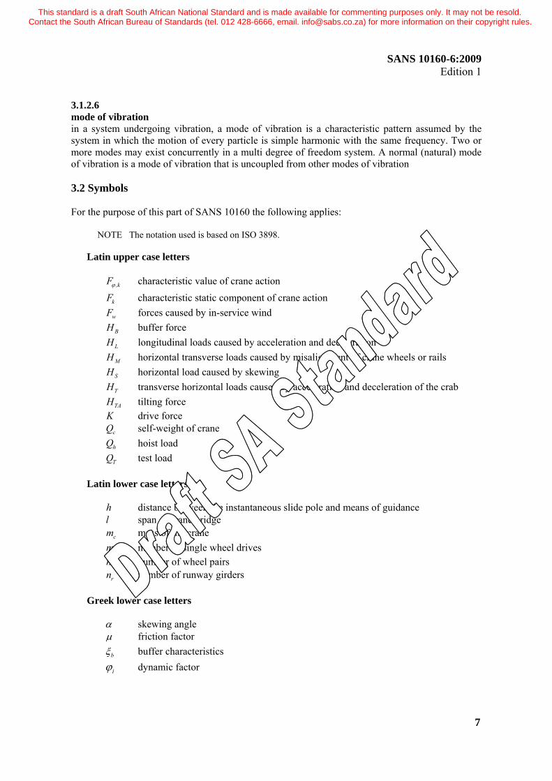
3.1.2.6 mode of vibration in a system undergoing vibration, a mode of vibration is a characteristic pattern assumed by the system in which the motion of every particle is simple harmonic with the same frequency. Two or more modes may exist concurrently in a multi degree of freedom system. A normal (natural) mode of vibration is a mode of vibration that is uncoupled from other modes of vibration 3.2 Symbols For the purpose of this part of SANS 10160 the following applies:
NOTE The notation used is based on ISO 3898.
Latin upper case letters ,kFϕ characteristic value of crane action
kF characteristic static component of crane action wF forces caused by in-service wind BH buffer force LH longitudinal loads caused by acceleration and deceleration MH horizontal transverse loads caused by misalignment of crane wheels or rails SH horizontal load caused by skewing TH transverse horizontal loads caused by acceleration and deceleration of the crab TAH tilting force K drive force cQ self-weight of crane hQ hoist load TQ test load
Latin lower case letters h distance between the instantaneous slide pole and means of guidance l span of crane bridge cm mass of the crane wm number of single wheel drives n number of wheel pairs rn number of runway girders
Greek lower case letters α skewing angle μ friction factor bξ buffer characteristics iϕ dynamic factor
This standard is a draft South African National Standard and is made available for commenting purposes only. It may not be resold. Contact the South African Bureau of Standards (tel. 012 428-6666, email. [email protected]) for more information on their copyright rules.
SANS 10160-6:2009 Edition 1
8
4 Actions induced by hoists and cranes on runway beams 4.1 Field of applications a) This Part specifies actions (models and representative values) induced by: Under-slung trolleys on runways, see 4.5.1 and 4.5.2 Overhead travelling cranes with both rails at the same level, see 4.5.3 and 4.5.4 Cranes with independent wheel pairs fixed in the longitudinal and transverse direction to the wheel block on the end carriages b) The definition of the actions induced by cranes on runways, are based on compliance of the supporting structure with the tolerances specified in SANS 2001 CSI. 4.2 Classification of actions 4.2.1 General Actions induced by cranes are classified as variable and accidental actions which are represented by various models. 4.2.2 Variable actions 4.2.2.1 For normal service conditions variable crane actions result from variation in time and location. They include gravity loads including hoist loads, inertial forces caused by acceleration and deceleration, skewing, misalignment of crane wheels or crane rails and other dynamic effects. 4.2.2.2 The variable crane actions should be separated into variable vertical crane actions caused by the self-weight of the crane and the hoist load; and variable horizontal crane actions caused by acceleration or deceleration, skewing, misalignment of crane wheels or crane rails and other dynamic effects. 4.2.2.3 The various representative values of variable crane actions are characteristic values composed of a static and a dynamic component. 4.2.2.4 Dynamic components induced by vibration due to inertial and damping forces are in general accounted for by dynamic factors φ to be applied to the static action value.
k i kF Fφ φ= (1) where kFφ is the characteristic value of a crane action iφ is the dynamic factor, see Table 1 kF is the characteristic static component of a crane action. 4.2.2.5 The various dynamic factors and their applications are listed in Table 1
This standard is a draft South African National Standard and is made available for commenting purposes only. It may not be resold. Contact the South African Bureau of Standards (tel. 012 428-6666, email. [email protected]) for more information on their copyright rules.

SANS 10160-6:2009 Edition 1
9
4.2.2.6 The simultaneity of the crane load components may be taken into account by considering groups of loads as identified in Table 2. Each of these groups of loads should be considered as defining one characteristic crane action for the combination with non-crane loads. NOTE The grouping provides that only one horizontal crane action is considered at a time.
Table 1 — Dynamic factors iφ
1 2 3 4 Dynamic factors Effects to be considered To be applied to Clause
φ1 excitation of the crane structure due to lifting the hoist load off the ground
self-weight of the crane 4.6.3
φ2 dynamic effects of transferring the hoist load from the ground to the crane
φ3 dynamic effect of sudden release of the payload if for example grabs or magnets are used
hoist load 4.6.3
φ4 dynamic effects induced when the crane is travelling on uneven rails or runways.
self-weight of the crane and hoist load
4.6.3
φ5 dynamic effects caused by drive forces drive forces 4.7.2(b)
φ6 dynamic effects of a test load moved by the drives in the way the crane is used
test load 4.10.4
φ7 dynamic effect of buffer characteristics buffer loads 4.12.1.2
This standard is a draft South African National Standard and is made available for commenting purposes only. It may not be resold. Contact the South African Bureau of Standards (tel. 012 428-6666, email. [email protected]) for more information on their copyright rules.
SANS 10160-6:2009 Edition 1
10
Table 2 — Groups of loads and dynamic factors to be considered as one characteristic crane action
1 2 3 4 5 6 7 8 9 10 11 12 13 14
Groups of loads
ULS Test load Accidental Load Symbol Clause
1 2 3 4 5 6 7 8 9 10 11 Self-weight of
crane c ,kQ 4.6 1φ 1φ 1 4φ 4φ 4φ 4φ 1 1φ 1 1
Hoist load hl ,kQ 4.6 2φ 3φ - 4φ 4φ 4φ 4φ - - 1 1
Part of hoist load
hl ,kQη (1) 4.6 - - - - - - - 1
Acceleration of crane bridge T LH ,H 4.7 5φ 5φ 5φ 5φ - - - - φ5 - -
Skewing of crane bridge SH 4.7 - - - - 1 - - - - - -
Acceleration or braking of crab or hoist
block 3T ,H 4.7 - - - - - 1 - - - - -
Misalignment of crane
wheels or gantry rails
MH 4.7 - - - - - - 1 - - - -
Test load TQ 4.10 - - - - - - - - 6φ - - Buffer force BH 4.12 - - - - - - - - - 7φ -
Tilting force TAH 4.12 - - - - - - - - - - 1 1) hl ,kQη is the part of the hoist load that remains when the payload is removed, but is not included in the self-weight of the crane
4.2.3 Accidental actions 4.2.3.1 Cranes may generate accidental actions due to collision with buffers (buffer forces) or collision of lifting attachments with obstacles. These actions should be considered for the structural design where appropriate protection is not provided. 4.2.3.2 Accidental actions described in 4.12 refer to common situations. They are represented by various load models defining design values (which are to be used with Aγ = 1,0) in the form of equivalent static loads. 4.2.3.3 The simultaneity of accidental crane load components may be taken into account by considering groups of loads as identified in Table 2. Each of these groups of loads defines one crane action for the combination with non-crane loads.
This standard is a draft South African National Standard and is made available for commenting purposes only. It may not be resold. Contact the South African Bureau of Standards (tel. 012 428-6666, email. [email protected]) for more information on their copyright rules.

SANS 10160-6:2009 Edition 1
11
4.3 Design situations 4.3.1 The relevant effects induced on cranes by actions not provided for in 4.2 shall be determined for each design situation identified in accordance with SANS 10160-1. 4.3.2 Selected design situations shall be considered and critical load cases identified. For each critical load case the design values of the effects of actions in combination shall be determined. 4.3.3 Multiple crane actions from several cranes are given in 4.5.5. 4.3.4 Combination rules for crane actions with other load models are given in SANS 10160-1. 4.3.5 In case tests are performed with cranes on the supporting structures for the serviceability limit state verification, the test loading model of the crane is specified in 4.10. 4.4 Representation of crane actions 4.4.1 The actions to be considered should be those exerted on the crane runway beams by the wheels of the cranes and possibly guide rollers or other guidance means. 4.4.2 Horizontal forces on crane supporting structures arising from horizontal movement of monorail hoist cranes and crane hoists should be determined from 4.5.2, 4.5.4 and 4.7. 4.5 Load arrangements 4.5.1 Vertical loads from monorail hoist blocks under-slung from runway beams For normal service conditions, the vertical load should be taken as composed of the self-weight of the hoist block, the hoist load and the dynamic factor, see Table 1 and Table 2. 4.5.2 Horizontal loads from monorail hoist blocks under-slung from runway beams In the case of fixed runway beams for monorail under-slung trolleys, in the absence of a more accurate value, the horizontal loads should be taken as 5% of the maximum vertical wheel load, neglecting the dynamic factor. 4.5.3 Vertical loads from overhead travelling cranes 4.5.3.1 The relevant vertical wheel loads from a crane on a runway beam, should be determined by considering the load arrangements illustrated in Figures 4(a) and 4(b), using the characteristic values given in 4.6.
This standard is a draft South African National Standard and is made available for commenting purposes only. It may not be resold. Contact the South African Bureau of Standards (tel. 012 428-6666, email. [email protected]) for more information on their copyright rules.

SANS 10160-6:2009 Edition 1
12
(a) Maximum vertical action on the runway beams
aa
Qr,min Qr,min ΣQr,min
L
ΣQr,(min) Qr,(min) Qr,(min)
(b) Minimum vertical actions on the runway beams
Figure 4 — Load arrangements where r ,maxQ is the maximum load per wheel of the loaded crane r ,(max)Q is the accompanying load per wheel of the loaded crane rΣ ,maxQ is the sum of the maximum loads r ,maxQ per runway of the loaded crane rΣ ,(max)Q is the sum of the accompanying maximum loads r ,(max)Q per runway of the loaded crane r ,minQ is the minimum load per wheel of the unloaded crane r ,(min)Q is the accompanying load per wheel of the unloaded crane rΣ ,minQ is the sum of the minimum loads r ,minQ per runway of the unloaded crane rΣ ,(min)Q is the sum of the accompanying minimum loads r ,(min)Q per runway of the unloaded crane hl,nomQ is the nominal hoist load
This standard is a draft South African National Standard and is made available for commenting purposes only. It may not be resold. Contact the South African Bureau of Standards (tel. 012 428-6666, email. [email protected]) for more information on their copyright rules.

SANS 10160-6:2009 Edition 1
13
4.5.3.2 The eccentricity of application e of a wheel load rQ to a rail should be taken as equal to a quarter of the width of the rail head rb , see Figure 5
Figure 5 — Eccentricity of application of vertical wheel load 4.5.4 Horizontal loads from overhead travelling cranes 4.5.4.1 The following types of horizontal loads from overhead travelling cranes should be taken into account: a) horizontal loads caused by acceleration or deceleration of the crane in relation to its movement
along the runway beam, see 4.7.2; b) horizontal loads caused by skewing of the crane in relation to its movement along the runway
beam, see 4.7.4; c) horizontal loads caused by acceleration or deceleration of the crab or under-slung trolley in
relation to its movement along the crane bridge, see 4.7.5; d) horizontal loads caused by misalignment of crane wheels, see 4.7.6; e) buffer forces related to the crane movement, see 4.12.1 and f) buffer forces related to the movement of the crab or under-slung trolley, see 4.12.2. 4.5.4.2 Unless otherwise specified, only one of the six types of horizontal loads listed in 4.5.4.1 should be included in the same group of simultaneous crane load components, see Table 2. 4.5.4.3 For under-slung cranes the horizontal loads at the wheel contact surface should be taken as at least 10% of the maximum vertical wheel load neglecting the dynamic component unless a more accurate value is justified. 4.5.4.4 Unless otherwise specified, the longitudinal horizontal wheel forces L,iH and the transverse horizontal wheel forces T,iH caused by acceleration and deceleration of the masses of the crane, should be applied as given in Figure 6. The characteristic values of these forces are given in 4.7.2.
This standard is a draft South African National Standard and is made available for commenting purposes only. It may not be resold. Contact the South African Bureau of Standards (tel. 012 428-6666, email. [email protected]) for more information on their copyright rules.

SANS 10160-6:2009 Edition 1
14
a
Figure 6 — Load arrangement of longitudinal and transverse
horizontal wheel forces caused by acceleration and deceleration. NOTE These forces do not include the effects of oblique hoisting due to misalignment of load and crab because in general oblique hoisting is forbidden. Any effects of unavoidable small values of oblique hoisting are included in the inertial forces. 4.5.4.5 The longitudinal and transverse horizontal wheel forces S.i.j.kH and the guide force S caused by skewing may occur at the guidance means of cranes or trolleys while they are travelling in steady state motion, see Figure 7. These loads are induced by guidance reactions which force the wheel to deviate from their free-rolling natural travelling direction. The characteristic values are given in 4.7.4.
a
a) With guidance by means of wheel flanges
a
b) With separate guidance means
Figure 7 — Load arrangement of longitudinal and transverse horizontal
wheel forces caused by skewing.
This standard is a draft South African National Standard and is made available for commenting purposes only. It may not be resold. Contact the South African Bureau of Standards (tel. 012 428-6666, email. [email protected]) for more information on their copyright rules.

SANS 10160-6:2009 Edition 1
15
NOTE The direction of the horizontal loads depends on the type of guidance means, the direction of motion and the type of wheel drive. 4.5.4.6 The transverse horizontal wheel forces T,3H may occur caused by acceleration or deceleration of the crab. The direction of the forces are shown in Figure 8. The characteristic values are given in 4.7.5.
a
Figure 8 — Load arrangement of transverse wheel forces caused by acceleration or deceleration of crab
4.5.4.7 The transverse horizontal wheel forces M,iH caused by misalignment of the crane wheels may occur at the wheels of cranes while they are travelling in steady state motion, see Figure 9. The direction of the forces M,iH can also be reversed. The characteristic values are given in 4.7.6.
RAIL i =2RAIL i =1
HM,1
HM,1 HM,2
HM,2L
Figure 9 — Load arrangement for transverse horizontal wheel forces caused by misalignment of crane wheels.
4.5.5 Multiple crane action 4.5.5.1 Cranes that are required to operate together shall be treated as a single action from a set of cranes. 4.5.5.2 If several cranes are operating independently, the maximum number of cranes taken into account as acting simultaneously should be as given in table 3. The combination of the actions from these cranes should be determined according to SANS 10160-1.
This standard is a draft South African National Standard and is made available for commenting purposes only. It may not be resold. Contact the South African Bureau of Standards (tel. 012 428-6666, email. [email protected]) for more information on their copyright rules.

SANS 10160-6:2009 Edition 1
16
Table 3— Maximum number of cranes to be considered in the most unfavourable position
1 2 3 4
Crane positions Cranes to each runway Cranes in each bay Cranes in multi-bay buildings
Crane action
Vertical 3 4 4 2
Horizontal 2 2 2 2 4.6 Vertical crane loads – characteristic values 4.6.1 The characteristic values of the vertical wheel loads from cranes on crane supporting structures should be determined as indicated in Table 2. 4.6.2 For the self-weight of the crane and the hoist load, the nominal values specified by the crane supplier shall be taken as the characteristic values of the vertical loads. 4.6.3 The dynamic factorsφ1 , φ2 , φ3 and φ4 specified in Table 1shall be determined in accordance with Table 4.
Table 4 — Dynamic factors iφ for vertical loads
1 2 Dynamic
factor Factor
φ1 1,1
φ2
h,min vφ β+ ×2 2 where hv is the steady hoisting speed in [m/s]
,minφ2 and β2 obtained from Table 5
φ3
( )mmΔ β− + 31 1
where mΔ is the released or dropped part of the load m total hoisting load β =3 0,5 for cranes equipped with grabs or similar slow release devices
β =3 1,0 for cranes equipped with magnets or similar rapid-release devices
φ4
1,0 provided that the tolerances for rail tracks specified in SANS 2001 CS1 are observed. NOTE : For tolerances outside the specifications of SANS 2001 CS1, the dynamic factor 4φ can be determined by the model given in Annex B.
This standard is a draft South African National Standard and is made available for commenting purposes only. It may not be resold. Contact the South African Bureau of Standards (tel. 012 428-6666, email. [email protected]) for more information on their copyright rules.

SANS 10160-6:2009 Edition 1
17
Table 5 — Values of β2 and ,minφ2
1 2 3
Class of crane β2 ,minφ2 C1 C2 C3 C4
0.17 0.34 0.51 0.68
1.05 1.10 1.15 1.20
NOTE Cranes are assigned to Class C1 to C4. The selection depends on the particular type of crane, see recommendations in Annex A.
4.7 Horizontal crane loads – characteristic values 4.7.1 General The characteristic values of the horizontal loads shall be determined in accordance with 4.7.2 to 4.7.6. 4.7.2 Loads Longitudinal loads L,1H and transverse loads T,iH caused by acceleration and deceleration of the crane shall consider the following: a) the longitudinal loads L,1H caused by acceleration and deceleration of the crane result from the drive force at the contact surface between the rail and the driven wheel (see Figure 10); b) the longitudinal loads L,1H applied to a runway beam calculated using Equation 2 :
L,ir
H Kn
φ= 51 (2)
where : rn is the number of runway beams K is the drive force according to 4.7.3 φ5 is the dynamic factor, see Table 6 i is the integer to identify the runway beam (i = 1,2).
This standard is a draft South African National Standard and is made available for commenting purposes only. It may not be resold. Contact the South African Bureau of Standards (tel. 012 428-6666, email. [email protected]) for more information on their copyright rules.

SANS 10160-6:2009 Edition 1
18
RAIL i =2RAIL i =1
HL,2HL,1
a
L
Figure 10 — Longitudinal horizontal loads L,1H c) the moment M resulting from the drive force applied at the centre of mass equilibrated by transverse horizontal loads T,1H and T,2H ,(see Figure 11). The horizontal loads are determined using Equations (3) and (4):
T ,MHa
φ ξ=1 5 2 (3)
T ,MHa
φ ξ=2 5 1 (4)
where ξ1 ( ) ( )r rΣ Σ,maxQ / Q= ξ2 ξ= − 11 rΣQ r rΣ Σ,max ,(max)Q Q= + r ,maxQΣ see Figure 4(a) a is the spacing of the guide rollers or the flanged wheels M SKL= SL ( ). Lξ= −1 05 L is the span of the crane bridge φ5 is the dynamic factor, see Table 6 K is the drive force, see 4.7.3
This standard is a draft South African National Standard and is made available for commenting purposes only. It may not be resold. Contact the South African Bureau of Standards (tel. 012 428-6666, email. [email protected]) for more information on their copyright rules.

SANS 10160-6:2009 Edition 1
19
RAIL i =2RAIL i =1
a
HT,2
HT,2
M
HT,1
HT,1K1
K=K1+K2 LS
K2
Lξ2Lξ1L
Centre ofgravity
Figure 11 — Definition of the transverse loads T,iH d) the resulting centrifugal force on the curved runway beams multiplied by the dynamic factor φ5 and e) for the dynamic factor φ 5 see Table 6, if it was not included in the specification documents of the crane supplier.
Table 6 — Dynamic factor φ5
1 2
Force description Dynamic factor
φ5
for centrifugal forces 1,0 correspond to systems in which forces change smoothly
1,5
when sudden changes occur 2,0 for drives with considerable backlash
3,0
4.7.3 Drive force K 4.7.3.1 The drive force K on the driven wheels should be taken such that wheel spin is prevented 4.7.3.2 The drive force K should be given by the crane supplier 4.7.3.3 Where no wheel controlled system is applied, the drive force K may be calculated as follows : rΣ ,minK K K Q*μ= + =1 2 (5) where : μ is the friction factor, see 4.7.3(d) For single wheel drives :
This standard is a draft South African National Standard and is made available for commenting purposes only. It may not be resold. Contact the South African Bureau of Standards (tel. 012 428-6666, email. [email protected]) for more information on their copyright rules.

SANS 10160-6:2009 Edition 1
20
w rΣ *r ,min ,minQ m Q= , with wm = number of single wheel drives
NOTE For central wheel drive : r rΣ *
r ,min ,min ,(min)Q Q Q= + , modern cranes do not normally have central wheel drive.
RAIL i =2RAIL i =1
a
K2K1
L
Figure 12 — Definition of drive force
4.7.3.4 The friction factor μ may be taken as : μ = 0.2 for steel – steel μ = 0.5 for steel – rubber 4.7.4 Horizontal loads S,i,j,TH and the guide force S caused by skewing of the crane 4.7.4.1 The guide force S and the transverse forces S,i,j,TH as indicated in Figure 14 caused by skewing may be obtained from : S S,j rf Qλ Σ= (6) S,1,j,TH S,1,j,T rf Qλ Σ= (7) S,2,j,TH S,2,j,T rf Qλ Σ= (8) where f is the friction factor according to 4.7.4.2 S,i,j,Tλ are the force factors see 4.7.4.4 i is the rail i j is the wheel pair j T is the direction of the force (T = transverse)
This standard is a draft South African National Standard and is made available for commenting purposes only. It may not be resold. Contact the South African Bureau of Standards (tel. 012 428-6666, email. [email protected]) for more information on their copyright rules.

SANS 10160-6:2009 Edition 1
21
4.7.4.2 The friction factor f may be determined from : ( )2500 3 1 0 3f , e ,α−= − ≤ (9)
where α is the skewing angle, see 4.7.4.3 4.7.4.3 The skewing angle α (see Figure 14) should be chosen taking into account the space between the guidance means and the rail as well as reasonable dimensional variation and wear of the crane wheels and the rails. The skewing angle α should be equal to or less than 0.015 rad. It may be determined as follows: F Vα α α α= + + ≤0 0,015 rad (10) where Fα , Vα and 0α are defined in Table 7 :
Table 7 — Definition of Fα , Vα and α0
1 2 Angles
iα Minimum values of iα
Fext
0 75, xa
α ×=
0,75 x≥ 5 mm for guide rollers 0,75 x ≥ 10 mm for flanged wheels
Vext
ya
α = y ≥ 0,03 b in mm for guide rollers
y ≥ 0,10 b in mm for flanged wheels
α0 α =0 0,001 where exta is the spacing of the outer guidance means or flanged wheels on the guiding rail in mm (see Figure 13) b is the width of the rail head in mm x is the track clearance between the rail and the guidance means (lateral slip including lateral float at wheels) in mm y is the wear of the rail and the guidance means in mm α0 is the tolerances of wheel and rail directions
This standard is a draft South African National Standard and is made available for commenting purposes only. It may not be resold. Contact the South African Bureau of Standards (tel. 012 428-6666, email. [email protected]) for more information on their copyright rules.

SANS 10160-6:2009 Edition 1
22
WITH SEPARATEGUIDANCE MEANS
GUIDANCE BYFLANGED WHEELS
Figure 13 — Definition of exta 4.7.4.4 The force factor S,i,j,Tλ depends on the combination of the wheel pairs and the distance h between the instantaneous centre of rotation and the relevant guidance means, i.e. the front guidance means in the direction of travel, see Figure 14. The value of the distance h may be determined from Equation 11. The force factor S,i,j,Tλ may be determined from the Equations (12) to (14).
j
j
eh
eΣΣ
=2
(11)
where : h is the distance between the instantaneous centre of rotation and the relevant guidance means je is the distance of the wheel pair j from the relevant guidance means
NOTE Equation 13 and Table 8 are applicable for cranes with independent wheel pairs which are fixed laterally. For the determination of h for cranes with different configurations, for example with coupled wheel pairs by means of a central drive or where the wheels on one side of the crane are free to move laterally, refer to EN 1991-3 or specialist literature.
jS,j
enhΣ
λ = −1 (12)
jS,1,j,T
en hξλ
⎛ ⎞= −⎜ ⎟
⎝ ⎠2 1 (13)
jS,2,j,T
en hξλ⎛ ⎞
= −⎜ ⎟⎝ ⎠
1 1 (14)
where : h is the distance between the instantaneous centre of rotation and the relevant guidance means je is the distance of the wheel pair j from the relevant guidance means
This standard is a draft South African National Standard and is made available for commenting purposes only. It may not be resold. Contact the South African Bureau of Standards (tel. 012 428-6666, email. [email protected]) for more information on their copyright rules.

SANS 10160-6:2009 Edition 1
23
n is the number of wheel pairs ξ1 is the fraction of the crane bridge span L between rail 1 and the instantaneous centre of rotation ξ2 is the fraction of the crane bridge span L between rail 2 and the instantaneous centre of rotation
CENTRE OF ROTATION
RAIL i =2RAIL i =1
WHEEL PAIR j
DIRECTIONOF TRAVEL
GUIDANCE MEANS
DIRECTION OF RAIL
y
x
HS,1,j,T HS,2,j,T
ej
h
INSTANTANEOUS
L
SKEWING ANGLE α
CENTRE OF GRAVITY
S
ξ1L ξ2L
Figure 14 — Definition of angle α and the distance h 4.7.5 Horizontal loads T,3H caused by acceleration or deceleration of the crab Provided that the payload is free to swing, the horizontal load T,3H representing the wheel forces related to the movement of the crab or trolley may be calculated according to Equation 15 : T,3H = 0,1(crab weight + hoist load) w/ n (15) where wn is the number of wheels on the crane
This standard is a draft South African National Standard and is made available for commenting purposes only. It may not be resold. Contact the South African Bureau of Standards (tel. 012 428-6666, email. [email protected]) for more information on their copyright rules.

SANS 10160-6:2009 Edition 1
24
4.7.6 Horizontal loads M,iH caused by misalignment of crane wheels The horizontal transverse loads M,iH caused by misalignment of crane wheels may be obtained from: ( )M,i M n n wH G Q / nμ= + (16) where Mμ factor depending on hoisting class of appliance (see Table 8) wn number of wheels nG self-weight of the crane nQ hoist load
Table 8 — Factor Mμ
Hoisting Class Mμ C1 0.05 C2 0.12 C3 0.15 C4 0.20
NOTE Cranes are assigned to Hoisting Class C1 to C4 depending on the particular type of crane, see Annex A. 4.8 Environmental effects 4.8.1 The action effects on runways due to temperature variations shall be taken into account where necessary. In general, non-uniform distributed temperature need not be considered. 4.8.2 The temperature difference for open gantry installations may be assumed to be ± 30 ºC for a mean temperature of +20 ºC. Refer to SANS 10160-7 for more detailed information on temperature actions. 4.8.3 Wind on crane and hoisted load in open gantry installations shall be determined in accordance with SANS 10160-3. 4.8.4 The actions induced by storm brakes on open gantry cranes should be obtained from the crane manufacturer. 4.9 Loads on access walkways, stairs, platforms and guard rails For loads on access walkways, stairs, platforms and guard rails the provisions for category E4 in SANS 10160-2 shall be used.
This standard is a draft South African National Standard and is made available for commenting purposes only. It may not be resold. Contact the South African Bureau of Standards (tel. 012 428-6666, email. [email protected]) for more information on their copyright rules.

SANS 10160-6:2009 Edition 1
25
4.10 Test loads 4.10.1 When tests are performed after erection of the cranes on the supporting structures, the supporting structures should be checked against the test loading conditions. 4.10.2 If relevant, the crane supporting structure should be designed for these test loads. 4.10.3 The test load shall be amplified by a dynamic factor φ6 . 4.10.4 When considering these test loads the following cases should be distinguished: a) Dynamic test load: The test load is moved by the drives in the way the crane will be used. The test load should be at least 110% of the nominal hoist load. ( )6 21 2/φ φ= + (17) b) Static test load: The load is increased for testing by loading the crane without the use of drives. The test load should be at least 125% of the nominal hoist load. 6 1 0,φ = (18) 4.11 Fatigue loads 4.11.1 The effects of fatigue on crane supporting structures shall be considered. They shall be carried out for loading groups 1, 2, 3, 4, 6, 7 and 8 from Table 2.. 4.11.2 The number of stress cycles for the determination of the effects of fatigue should be determined in accordance with the intended use and design life of the structure. 4.12 Accidental actions 4.12.1 Buffer forces B,H 1related to crane movement 4.12.1.1 Where buffers are used, the forces on the crane supporting structure arising from collision with the buffers shall be calculated from the kinetic energy of all relevant parts of the crane including the hoist load moving at 0.7 to 1.0 times nominal speed. 4.12.1.2 The buffer forces multiplied by φ7 according to Table 9 to make allowance for dynamic effects may be calculated taking into account the distribution of relevant masses and the buffer characteristics, see Figure 15. B c B,H v m Sφ=1 7 1 (19)
This standard is a draft South African National Standard and is made available for commenting purposes only. It may not be resold. Contact the South African Bureau of Standards (tel. 012 428-6666, email. [email protected]) for more information on their copyright rules.

SANS 10160-6:2009 Edition 1
26
where : φ7 see Table 9 for determination v1 is 70% of the long travel velocity [m/s] cm is the mass of the crane and the hoist load [kg] BS is the spring constant of the buffer [N/m]
Table 9 — Dynamic factor φ7
φ =7 1,25 if 0,0 bξ≤ ≤ 0,5
φ =7 1,25+0,7( bξ - 0,5) if b0 5 1 0. .ξ≤ ≤
bξ may be approximately determined from Figure 11 depending on buffer characteristics
RAIL i =2RAIL i =1
Fx1 Fx2
δ δ
Fx1 Fx2
Figure 15 — Buffer forces
φ 7
Figure 16 — Definition of bξ
This standard is a draft South African National Standard and is made available for commenting purposes only. It may not be resold. Contact the South African Bureau of Standards (tel. 012 428-6666, email. [email protected]) for more information on their copyright rules.

SANS 10160-6:2009 Edition 1
27
4.12.2 Buffer forces B,2H related to movements of the crab Provided that the payload is free to swing, the horizontal load B,2H representing the buffer forces related to the movement of the crab or trolley may be taken as 10% of the sum of the hoist load and the weight of the crab or trolley. In other cases the buffer forces should be determined as for crane movement, see 4.12.1. 4.12.3 Tilting forces If a crane with horizontally restrained loads can tilt when its load or lifting attachment collides with an obstacle, the resulting static forces shall be considered. 4.12.4 Crane movement due to wind on an open gantry installation 4.12.4.1 Crane movement may result where wind forces on the crane on an open gantry installation exceeds the braking forces and positive clamping devices are not applied. 4.12.4.2 The impact on the end buffers due to this movement shall be considered. The buffer forces should be determined in accordance with 4.12.1 where v1 is calculated in an appropriate manner. 5 Limit states design verification Limit states design verification shall be done in accordance with SANS 10160-1. 5.1 Combination values for crane induced actions The combination factor for crane induced actions should be determined from Equation 20 :
c ,kcrane
c ,k hl ,k
QQ Q
ψ =+
(20)
5.2 Crane induced actions for the ultimate limit state a) The representative wheel load induced by cranes to be used in 4.3.2.2 is given by wl ,kQ for the persistent, transient (test load) and accidental actions as determined for the various groups of loads according to 4.2.2.6. 5.3 Crane induced actions for the serviceability limit state a) The combination of actions for the reversible and the irreversible serviceability limit states are determined in accordance with SANS 10160-1. b) The serviceability criteria should be specified in accordance with the guidelines provided in Annex C. Deviation from these guidelines may be considered when justified.
This standard is a draft South African National Standard and is made available for commenting purposes only. It may not be resold. Contact the South African Bureau of Standards (tel. 012 428-6666, email. [email protected]) for more information on their copyright rules.

SANS 10160-6:2009 Edition 1
28
6 Actions induced by machinery 6.1 Field of application 6.1.1 This clause applies to structures supporting rotating machines which induce harmonic dynamic effects in one or more planes. NOTE For non-harmonic loading specialist literature should be consulted. 6.1.2 This clause presents methods to determine the dynamic behaviour and action effects to verify the safety of the structure. NOTE Though a sharp bound cannot be set, in general it may be assumed that for minor machinery with only rotating parts and weighting less than 5 kN or having a power less than 50 kW, the action effects are included in the imposed loads and separate considerations are therefore not necessary. In these cases the use of so called vibration absorbers under the supporting frame is sufficient to protect the machine and the surroundings. Examples are washing machines and small fans. 6.2 Classification of actions 6.2.1 General Actions from machinery are classified as permanent, variable static and variable dynamic, and accidental actions which are represented by various models. 6.2.2 Permanent actions 6.2.2.1 Permanent actions during service include the self-weight of all fixed and moveable parts and static actions from service such as: a) self-weight of rotors and the casing (vertical) b) self-weight of condensors, gearboxes and other fixed equipment (vertical) 6.2.2.2 Permanent actions during transient stages (erection, maintenance or repair) are those from self-weight only including those from hoisting equipments, scaffolding or other auxiliary devices. 6.2.3 Variable actions 6.2.3.1 Variable static actions 6.2.3.1.1 Variable static actions during service include the actions from service and imposed loads such as: a) water infill of condensers, or the oil infill in gearboxes (vertical) b) actions from vacuum for turbines, the condensers of which are connected to the casing by compensators (vertical and horizontal) c) drive torques of the machine transmitted to the foundation by the casing (pairs of vertical forces)
This standard is a draft South African National Standard and is made available for commenting purposes only. It may not be resold. Contact the South African Bureau of Standards (tel. 012 428-6666, email. [email protected]) for more information on their copyright rules.

SANS 10160-6:2009 Edition 1
29
d) forces from friction at the bearings induced by thermal expansion of the casing (horizontal) e) actions, forces and moments from pipes due to thermal expansion, actions from gas flow and gas pressure (vertical and horizontal) f) temperature effects from the machine and pipes for instance temperature differences between machine and pipes and foundations. 6.2.3.1.2 Variable static actions during transient stages (erection, maintenance or repair) are those from self-weight only including those from hoisting equipment, or other auxiliary devices and imposed loads on scaffolding. 6.2.3.2 Variable dynamic actions Variable dynamic actions from machinery during normal service are dynamic actions caused by accelerated masses such as: a) periodic frequency dependent bearing forces due to eccentricities of rotating masses in all directions, mainly perpendicular to the axis of the rotors b) free mass forces or mass moments c) periodic actions due to service, depending on the type of machine, that are transmitted by the casing or bearings to the foundations d) forces or moments due to switching on or off or other transient procedures such as synchronizations. 6.2.4 Accidental actions Accidental actions may occur from: a) accidental magnification of the eccentricity of masses (for instance by fracture of blades or accidental deformation of moveable parts) b) short circuit or mis-synchronization between generators and machines c) impact effects from pipes by shutting down (i.e. water hammer). 6.3 Design situations 6.3.1 The relevant actions induced by machinery shall be determined for each design situation identified in accordance with SANS 10160-1. 6.3.2 Design situations shall in particular be selected for verifying that: a) the service conditions of the machinery are in compliance with the service requirements and no damage is induced to the structure supporting the machine and its foundation by accidental actions that would infringe the subsequent use of this structure for further service;
This standard is a draft South African National Standard and is made available for commenting purposes only. It may not be resold. Contact the South African Bureau of Standards (tel. 012 428-6666, email. [email protected]) for more information on their copyright rules.

SANS 10160-6:2009 Edition 1
30
b) the effect on the surroundings, for instance disturbance of sensitive equipment or people, is within acceptable limits; c) no ultimate limit state may occur in the structure; d) no fatigue limit state may occur in the structure. NOTE Unless specified otherwise, the serviceability and vibration sensitivity requirements should be determined in contracts and/or in the design. 6.4 Representation of actions 6.4.1 Nature of the loads 6.4.1.1 In the determination of action effects a distinction shall be made between the static and the dynamic action effects. 6.4.1.2 In the static actions both those from machinery and those from the structure shall be included.
NOTE The static actions from the machinery are the permanent actions defined in 6.2.2., and the variable static actions defined in 6.2.3.1. They may be used for determining creeping effects or when limitations of static deformations are given. 6.4.1.3 The dynamic action effects shall be determined taking into account the interaction between the excitation from the machinery and the structure. NOTE The dynamic actions from the machinery are the variable dynamic actions defined in 6.2.3.2 6.4.1.4 Dynamic action effects shall be determined by a dynamic calculation with an appropriate modelling of the vibration system and the dynamic action. 6.4.1.5 Dynamic effects may be disregarded where not relevant. 6.4.2 Modelling of dynamic actions 6.4.2.1 The dynamic actions of machines with only rotating parts, for instance rotating compressors, turbines, generators and fans, consist of periodically changing forces which may be defined by a sinusoidal function. 6.4.1.2 A short circuit torque ( )kM t may be represented by a combination of sinusoidal torque-time diagrams acting between the rotor and the casing. 6.4.3 Modelling of the machinery-structure interaction 6.4.3.1 The vibration system composed of the machine and the structure shall be modelled such, that the excitations, the mass quantities, stiffness properties and the damping are sufficiently taken into account to determine the actual dynamic behaviour. 6.4.3.2 The model may be linear elastic with concentrated or distributed masses connected with springs and supported by springs.
This standard is a draft South African National Standard and is made available for commenting purposes only. It may not be resold. Contact the South African Bureau of Standards (tel. 012 428-6666, email. [email protected]) for more information on their copyright rules.

SANS 10160-6:2009 Edition 1
31
6.4.3.3 In general the three possible degrees of freedom for translations and the three degrees of freedom for rotations should be considered; it is however for structures within the scope of this section (see 6.1) generally not necessary to apply a three dimensional model. 6.4.3.4 The properties of the supporting medium of the foundation structure should be converted in terms of the model (springs, damping constants etc.). The required properties are: a) for soils: dynamic G -modulus and damping constants; b) for piles: dynamic spring constants in vertical and horizontal directions c) for springs: spring constants in horizontal and vertical directions and for rubber springs the damping data. 6.4.3.5 The dynamic analysis of the system should be carried out using a high and a low assumption of the properties of isolating springs, to establish upper and lower bounds to dynamic actions. 6.4.3.6 The analysis must consider at least sufficient vibration modes to include all frequencies up to 1,5 times the operating frequency of the equipment. 6.5 Special considerations 6.5.1 In the case of machines mounted on concrete block foundations, the common centre of gravity of the system should be located as near as possible to the same vertical line as the centroid of the foundation area in contact with the soil. In any case the eccentricity in the distribution of masses should not exceed 5% of the length of the side of the contact area. In addition, the centre of gravity of the machine and foundation system should if possible be below the top of the foundation block. 6.5.2 Notional excitations equivalent to 5% of the main variable dynamic loading should be applied orthogonally to the main direction of application to account for eccentricities or different support characteristics. 6.6 Characteristic values 6.6.1 A complete survey of the static and dynamic forces for the various design situations should be supplied by the machine manufacturer together with all other machine data such as outline drawings, weights of static and moving parts, speeds, balancing etc. 6.6.2 The following data should be made available to the designer by the machine manufacturer: a) loading diagram of the machine showing the location, magnitude and direction of all loads including dynamic loads b) speed of the machine c) critical speeds of the machine d) outline dimensions of the foundation
This standard is a draft South African National Standard and is made available for commenting purposes only. It may not be resold. Contact the South African Bureau of Standards (tel. 012 428-6666, email. [email protected]) for more information on their copyright rules.

SANS 10160-6:2009 Edition 1
32
e) mass moment of inertia of the machine components f) layout of piping, ducting etc, and their supporting details; – temperatures in various zones during operation g) allowable displacements at the machine bearing points during normal operation h) masses and position of centres of gravity of main mechanical components i) force-displacement characteristics and damping characteristics of special support components such as springs and hangers 6.6.3 In simple cases, the dynamic forces (free forces) for rotating machine parts may be determined using Equation 21 : s R sF m eω= 2 (21) where:
sF is the free force of the rotor;
Rm is the mass of the rotor;
sω is the circular frequency of the rotor e is the eccentricity of the rotor mass 6.6.4 For the determination of the free forces to be used in the design, the following situations should be considered: a) persistent situation for balanced machines (such as motors and fans): b) the machine is well balanced. However with time the balance of the machines decreases to a degree that is just acceptable for normal operation. A warning system on the machine ensures that the operator is warned in case of exceeding a certain limit. Up to that state of balance no vibration hindrance may occur to the structure and the surroundings and the requirements concerning the vibration level must be fulfilled. c) persistent situation for vibrating machines (such as screens and feeders): d) the eccentricity of the masses is set to the maximum amount. e) accidental situation for balanced machines: f) the balance is completely disturbed by an accidental event and the monitoring system achieves the switch off of the machine. The structure must be strong enough to withstand the dynamic forces.
This standard is a draft South African National Standard and is made available for commenting purposes only. It may not be resold. Contact the South African Bureau of Standards (tel. 012 428-6666, email. [email protected]) for more information on their copyright rules.

SANS 10160-6:2009 Edition 1
33
6.6.5 In simple cases the interaction effect from the excitation of a machine with a rotating mass and the dynamic behaviour of the structure may be expressed by a static equivalent force given in Equation 22 eq sF F v= (22) where:
sF is the free force of the rotor; v is the magnification factor which depends on the ratio of the natural frequency en (or eω )
of the structure to the frequency of the exciting force sn (or sω ) and the damping ratio D . 6.6.6 For harmonically varying forces (free forces of rotating equipment) the magnification factor may be taken in the following way: a) for small damping and far from resonance
e
e s
v ωω ω
=−
2
2 2 (23)
b) close to resonance e sω ω≈ and a damping ratio D
12 2 22
s s2
e e
1 2v Dω ωω ω
−⎡ ⎤⎛ ⎞ ⎛ ⎞⎢ ⎥= − +⎜ ⎟ ⎜ ⎟⎢ ⎥⎝ ⎠ ⎝ ⎠⎣ ⎦
(24)
6.6.7 If the time history of the short circuit torque Mk(t) is not indicated by the manufacturer, the following equation may be used:
( ) ( )2 5
2 5 6 7k 0 N N 010 2 1
2
, t, t , teM t M e sin t sin t M eΩ Ω
−− −⎛ ⎞
= − − −⎜ ⎟⎝ ⎠
(25)
where:
0M is the nominal torque resulting from the effective power; NΩ is the frequency of the electric net; t is the time [s]. 6.6.8 For natural frequencies in the range 0.95 NΩ to 1.05 NΩ , it should be assumed that the frequency of the electric net is identical with these natural frequencies. 6.6.9 As a simplification, an equivalent static action may be considered to determine the torque as below:
This standard is a draft South African National Standard and is made available for commenting purposes only. It may not be resold. Contact the South African Bureau of Standards (tel. 012 428-6666, email. [email protected]) for more information on their copyright rules.

SANS 10160-6:2009 Edition 1
34
k,eq k1 7 ,maxM . M= (26) where: k ,maxM is the peak value of ( )kM t . 6.6.10 In case no indication of k ,maxM is given by the manufacturer, the following value may be used: k,max 012M M= (27) 6.7 Serviceability criteria 6.7.1 Serviceability criteria in general are related to vibration movements of; a) the axis of the machine and its bearings and b) extreme points of the structure and the machinery. 6.7.2 Characteristics of the movements are: a) the displacement amplitude A ; b) the velocity amplitude s Aω and c) the acceleration amplitude s Aω2 6.7.3 In calculating the amplitudes of the system, the translational vibrations as well as the rotational vibrations caused by the dynamic forces and moments shall be taken into account and also the spread in the stiffness properties of the foundation and the supporting medium (soil, piles). 6.7.4 In the simple case of a one mass spring system, Figure 17, the displacement amplitudes may be calculated as follows:
sFAk
= (28)
where: k is the spring constant of the system.
This standard is a draft South African National Standard and is made available for commenting purposes only. It may not be resold. Contact the South African Bureau of Standards (tel. 012 428-6666, email. [email protected]) for more information on their copyright rules.

SANS 10160-6:2009 Edition 1
35
AFs
m
ck
Figure 17 — Mass spring system
This standard is a draft South African National Standard and is made available for commenting purposes only. It may not be resold. Contact the South African Bureau of Standards (tel. 012 428-6666, email. [email protected]) for more information on their copyright rules.

SANS 10160-6:2009 Edition 1
36
Annex A (Informative)
Guidance for crane classification
The recommendations for the classification of cranes are given in Table A.1.
Table A.1 — Recommendations for crane classes
Item Type of crane Class of Crane 1 Hand operated cranes C1 2 Assembly cranes C1, C2 3 Power station cranes C2 4 Warehouse cranes – with intermittent operation C2 5 Warehouse cranes - continuous operation C3 6 Scrap yard cranes – with continuous operation C3, C4 7 Workshop cranes, machine shop cranes C2, C3 8 Cranes with grab or magnet C3, C4 9 Claw cranes C4
10 Casting cranes, foundry cranes C2 11 Ladle cranes C3 12 Soaking pit cranes C4 13 Stripper cranes, furnace charging cranes C4 14 Forging cranes C4
This standard is a draft South African National Standard and is made available for commenting purposes only. It may not be resold. Contact the South African Bureau of Standards (tel. 012 428-6666, email. [email protected]) for more information on their copyright rules.

SANS 10160-6:2009 Edition 1
37
Annex B (Informative)
Example of a model for estimating the value of the dynamic
factor 4φ for a crane travelling on rails B.1 General The dynamic loads caused by travelling on rails with steps or gaps may be estimated by using appropriate elasto-kinetic models. Unevenness functions may be used to represent the steps or gaps in the rail (see ISO 8686-1) B.2 Elasto-kinetic model B.2.1 General In this example, the dynamic loads on the crane caused by excitation of the system are estimated using a simple single-degree of freedom model. A single mass m , in [kg], moving horizontally at constant speed v , in [m/sec], is supported by a linear elastic spring with a spring constant c , in [N/m], and is guided by a rail as shown in Figure B.1. With the unevenness function ( )h t , in [m], and the coordinate ( )z t , in [m], describing the position of the spring supported mass, the dynamic force in the spring, in [N], follows from equation (B.1). ( ) ( ) ( )F t c h t z t⎡ ⎤= −⎣ ⎦ (B.1) The maximum force maxF is given by the maximum value of the equation (B.1) during the period of response. This may occur during or after the period of excitation.
Figure B.1 — Single degree of freedom model for determining the dynamic factor φ4
This standard is a draft South African National Standard and is made available for commenting purposes only. It may not be resold. Contact the South African Bureau of Standards (tel. 012 428-6666, email. [email protected]) for more information on their copyright rules.

SANS 10160-6:2009 Edition 1
38
B.2.2 Movement of the wheel centre when passing over a step or a gap The movement of the wheel centre when passing over a step or a gap and the corresponding equations are shown in Figure B.2.
hses
r r r
eGhG
( )S s Se rh h r= <<2 ( )GG G
eh e rr
= ≈2
8
a) Passing over a step b) Passing over a gap
Figure B.2 — Movement of wheel centre
B.2.3 Approximate unevenness functions for exciting the elasto-kinetic model The approximate unevenness functions for exciting the elasto-kinetic model and the corresponding equations are shown in Figure B.3.
h S
h G
( ) ( )Shh t cos tΩ= −12
( ) ( )Ghh t cos tΩ= −12
where StΩ π= where GtΩ π= 2 a) Passing over a step b) Passing over a gap
Figure B.3 — Unevenness functions ( )h t
This standard is a draft South African National Standard and is made available for commenting purposes only. It may not be resold. Contact the South African Bureau of Standards (tel. 012 428-6666, email. [email protected]) for more information on their copyright rules.

SANS 10160-6:2009 Edition 1
39
B.2.4 Maximum vertical accelerations B.2.4.1 Lower end spring The maximum vertical acceleration of the lower end of the spring when passing over a step or a gap at constant speed is given in equation B.2.
..
S Gh h vhr
πΩ Ω ⎛ ⎞= = = ⎜ ⎟⎝ ⎠
2 22 2
2 2 2 (B.2)
where
..h is the maximum vertical acceleration of the lower end of the spring
v is the constant speed of the crane B.2.4.2 Mass passing a step The maximum vertical acceleration for the mass m passing a step is given in equation B.3.
( ).. ..
S Sz hξ α= (B.3) where
SS
h rv h
ωαπ
=2
cm
ω = the natural circular frequency of the elasto-kinetic model
B.2.4.3 Mass passing a gap The maximum vertical acceleration for a mass m passing a gap is given in equation B.4.
( ).. ..
G Gz hξ α= (B.4) where
GG
ev
ωα
π=
2
B.2.5 Factors Sξ and Gξ For both excitations, moving over a step or a gap, the maximum values of Sξ or Gξ have been found to occur during the response of the single degree of freedom elasto-kinetic system after the step or the gap has been passed. In this case, the values of the factors may be determined analytically as given in equations (B.5) and ( B.6) respectively.
This standard is a draft South African National Standard and is made available for commenting purposes only. It may not be resold. Contact the South African Bureau of Standards (tel. 012 428-6666, email. [email protected]) for more information on their copyright rules.

SANS 10160-6:2009 Edition 1
40
( )SS S
S
cosαξ πα
α= +
−
2
2 2 21
(B.5)
( )GG G
G
cosαξ πα
α= −
−
2
2 2 2 21
(B.6)
B.2.6 Dynamic factor φ4 The dynamic factor φ4 is defined as follows :
.. ..
mg m z hmg g
φ ξ+= = +4 1
For the two cases and the assumptions made, the factors φ4 may be calculated as given in equations (B.7) and (B.8). For a step :
Svgr
πφ ξ⎛ ⎞= + ⎜ ⎟⎝ ⎠
2 2
4 12
(B.7)
For a gap :
Gvgr
πφ ξ⎛ ⎞= + ⎜ ⎟⎝ ⎠
2 2
4 12
(B.8)
B.3 Comments The use of this simple elasto-kinetic model is restricted to cranes whose actual dynamic behaviour corresponds to that of the model and which are excited in the manner shown by passing over steps or gaps in the rails. If more than one natural mode contributes a significant response and / or rotation occurs, the designer should estimate the dynamic loads using an appropriate model for the circumstances.
This standard is a draft South African National Standard and is made available for commenting purposes only. It may not be resold. Contact the South African Bureau of Standards (tel. 012 428-6666, email. [email protected]) for more information on their copyright rules.

SANS 10160-6:2009 Edition 1
41
Annex C (Informative)
Guidance for serviceability design criteria
The recommendations for serviceability design criteria are given in Table C.1.
Table C.1 — Recommendations for serviceability design criteria
Direction of
deflection
Design load Application Range of maximum deflections
Vertical Maximum wheel loads
Simple span crane runway girders 600
1 of span
to 1800 of span
For small class 1 crane to heavy class 4 crane
Horizontal Crane lateral forces
Simple span crane runway girders 600
1 of span
to 1800 of span
For small class 1 crane to heavy class 4 crane
Horizontal Crane lateral forces or wind loads
Building column sway at crane level (1)
1200
to 1
400 of height
For all classes of cranes
1) Permissible sway of industrial buildings varies considerably and depends on such factors as wall construction, building height, effect of deflection on the operation of the crane. Where the operation of the crane is sensitive to lateral deflections, a permissible lateral deflection of less than 1/400 of the height may be required.
© SABS
This standard is a draft South African National Standard and is made available for commenting purposes only. It may not be resold. Contact the South African Bureau of Standards (tel. 012 428-6666, email. [email protected]) for more information on their copyright rules.