Embed Size (px)
Citation preview
Document Number 2620002R Code Identification 0WY55
WSR-88D ROC Build Date TBD
Draft Copy Open Build 18.0
DRAFT
INTERFACE CONTROL DOCUMENT FOR THE RDA/RPG
Prepared by: WSR-88D Radar Operations Center
1313 Halley Circle Norman, OK 73069
APPROVED FOR USE AS PRODUCT BASELINE BY & SUBMITTED BY: DATE: _______________
Cheryl A. Stephenson Chief, Program Branch WSR-88D Radar Operations Center
DISTRIBUTION STATEMENT A: Approved for public release; distribution unlimited.
Document Number 2620002R Code Identification 0WY55
WSR-88D ROC Build Date TBD
Draft Copy Open Build 18.0
R-1
DRAFT
INTERFACE CONTROL DOCUMENT FOR THE RDA/RPG
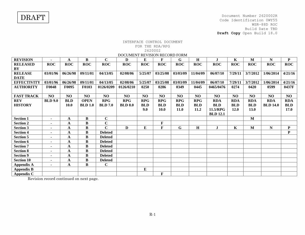
2620002 DOCUMENT REVISION RECORD FORM
REVISION - A B C D E F G H J K M N P RELEASED BY
ROC ROC ROC ROC ROC ROC ROC ROC ROC ROC ROC ROC ROC ROC
RELEASE DATE
03/01/96 06/26/98 09/11/01 04/13/05 02/08/06 5/25/07 03/25/08 03/03/09 11/04/09 06/07/10 7/29/11 3/7/2012 1/06/2014 4/21/16
EFFECTIVITY 03/01/96 06/26/98 09/11/01 04/13/05 02/08/06 5/25/07 03/25/08 03/03/09 11/04/09 06/07/10 7/29/11 3/7/2012 1/06/2014 4/21/16 AUTHORITY F0048 F0095 F0103 0126/0209 0126/0210 0250 0286 0349 0445 0465/0476
0274 0420 0599 0437F
FAST TRACK NO NO NO NO NO NO NO NO NO NO NO NO NO NO REV HISTORY
BLD 9.0 BLD 10.0
OPEN BLD 1.0
RPG BLD 7.0
RPG BLD 8.0
RPG BLD 9.0
RPG BLD 10.0
RPG BLD 11.0
RPG BLD 11.2
RDA BLD
11.5/RPG BLD 12.1
RDA BLD 12.0
RDA BLD 13.0
RDA BLD 14.0
RDA BLD 17.0
Section 1 - A B C M Section 2 - A B C F Section 3 - A B C D E F G H J K M N P Section 4 - A B Deleted P Section 5 - A B Deleted Section 6 - A B Deleted Section 7 - A B Deleted Section 8 - A B Deleted Section 9 - A B Deleted Section 10 - A B Deleted Appendix A - A B C Appendix B E Appendix C F
Revision record continued on next page.
Document Number 2620002R Code Identification 0WY55
WSR-88D ROC Build Date TBD
Draft Copy Open Build 18.0
R-2
DRAFT
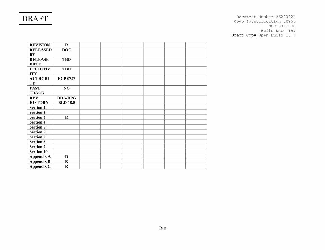
REVISION R RELEASED BY
ROC
RELEASE DATE
TBD
EFFECTIVITY
TBD
AUTHORITY
ECP 0747
FAST TRACK
NO
REV HISTORY
RDA/RPG BLD 18.0
Section 1 Section 2 Section 3 R Section 4 Section 5 Section 6 Section 7 Section 8 Section 9 Section 10 Appendix A R Appendix B R Appendix C R
Document Number 2620002R Code Identification 0WY55
WSR-88D ROC Build Date TBD
Draft Copy Open Build 18.0
R-3
DRAFT
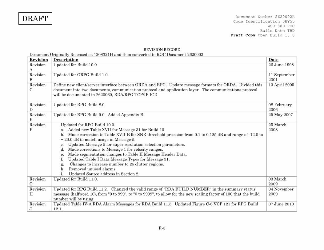
REVISION RECORD
Document Originally Released as 1208321H and then converted to ROC Document 2620002 Revision Description Date Revision A
Updated for Build 10.0 26 June 1998
Revision B
Updated for ORPG Build 1.0. 11 September 2001
Revision C
Define new client/server interface between ORDA and RPG. Update message formats for ORDA. Divided this document into two documents, communication protocol and application layer. The communications protocol will be documented in 2620060, RDA/RPG TCP/IP ICD.
13 April 2005
Revision D
Updated for RPG Build 8.0 08 February 2006
Revision E
Updated for RPG Build 9.0. Added Appendix B. 25 May 2007
Revision F
Updated for RPG Build 10.0. a. Added new Table XVII for Message 31 for Build 10. b. Made correction to Table XVII-B for SNR threshold precision from 0.1 to 0.125 dB and range of -12.0 to + 20.0 dB to match usage in Message 5. c. Updated Message 5 for super resolution selection parameters. d. Made corrections to Message 1 for velocity ranges. e. Made segmentation changes to Table II Message Header Data. f. Updated Table I Data Message Types for Message 31. g. Changes to increase number to 25 clutter regions. h. Removed unused alarms. i. Updated Source address in Section 2.
25 March 2008
Revision G
Updated for Build 11.0. 03 March 2009
Revision H
Updated for RPG Build 11.2. Changed the valid range of "RDA BUILD NUMBER" in the summary status message (halfword 10), from "0 to 999", to "0 to 9999", to allow for the new scaling factor of 100 that the build number will be using.
04 November 2009
Revision J
Updated Table IV-A RDA Alarm Messages for RDA Build 11.5. Updated Figure C-6 VCP 121 for RPG Build 12.1.
07 June 2010

Document Number 2620002R Code Identification 0WY55
WSR-88D ROC Build Date TBD
Draft Copy Open Build 18.0
R-4
DRAFT
Revision K
RDA Build 12.0 changes for Dual Polarization. 29 July 2011
Revision M
Updated for RDA Build 13.0. 7 March 2012
Revision N
Updated for RDA/RPG Build 14.0 CCRs Affected: NA12-00299, NA12-00018, NA12-00019, NA12-00378, NA12-00233, NA12-00046, NA12-00023, NA12-00022, NA12-00373, NA12-00046, NA13-00044, NA12-00022, NA12-00023, NA12-00256, NA12-00421, NA11-00198, NA12-00234, NA12-00338, NA13-00111
06 January 2014
Revision P
Updated for RDA Build 17.0. 21 April 2016
Revision R
Updated for RDA and RPG Build 18.0. TBD
Document Number 2620002R Code Identification 0WY55
WSR-88D ROC Build Date TBD
Draft Copy Open Build 18.0
i
DRAFT
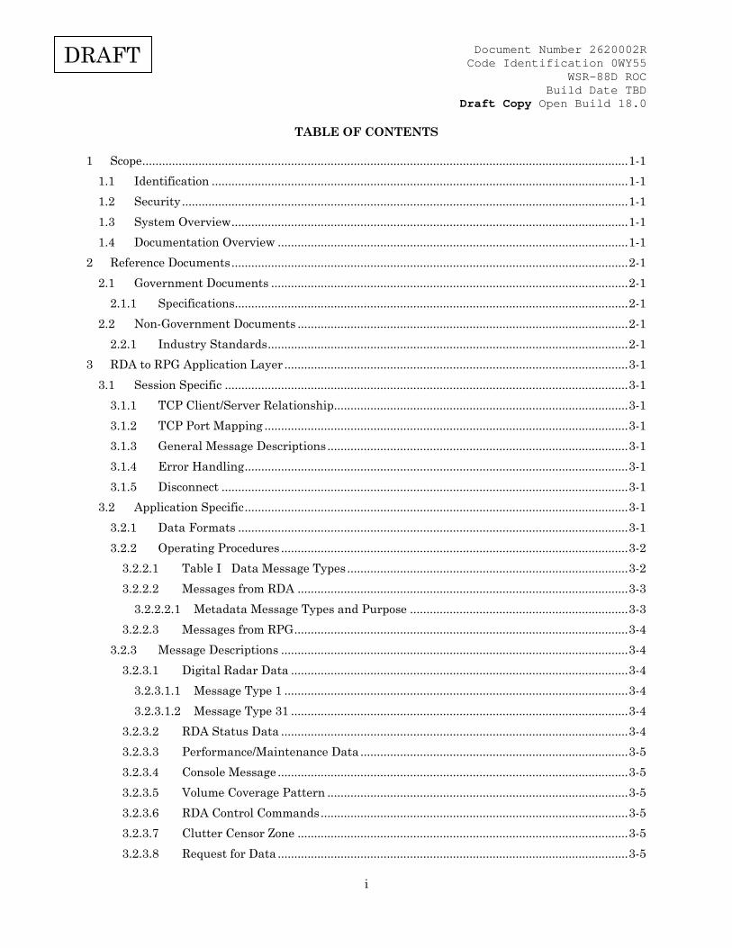
TABLE OF CONTENTS
1 Scope ................................................................................................................................................... 1-1 1.1 Identification .............................................................................................................................. 1-1 1.2 Security ....................................................................................................................................... 1-1 1.3 System Overview ........................................................................................................................ 1-1 1.4 Documentation Overview .......................................................................................................... 1-1
2 Reference Documents ........................................................................................................................ 2-1 2.1 Government Documents ............................................................................................................ 2-1
2.1.1 Specifications ....................................................................................................................... 2-1 2.2 Non-Government Documents .................................................................................................... 2-1
2.2.1 Industry Standards ............................................................................................................. 2-1 3 RDA to RPG Application Layer ........................................................................................................ 3-1
3.1 Session Specific .......................................................................................................................... 3-1 3.1.1 TCP Client/Server Relationship ......................................................................................... 3-1 3.1.2 TCP Port Mapping .............................................................................................................. 3-1 3.1.3 General Message Descriptions ........................................................................................... 3-1 3.1.4 Error Handling .................................................................................................................... 3-1 3.1.5 Disconnect ........................................................................................................................... 3-1
3.2 Application Specific .................................................................................................................... 3-1 3.2.1 Data Formats ...................................................................................................................... 3-1 3.2.2 Operating Procedures ......................................................................................................... 3-2
3.2.2.1 Table I Data Message Types ..................................................................................... 3-2 3.2.2.2 Messages from RDA .................................................................................................... 3-3
3.2.2.2.1 Metadata Message Types and Purpose .................................................................. 3-3 3.2.2.3 Messages from RPG ..................................................................................................... 3-4
3.2.3 Message Descriptions ......................................................................................................... 3-4 3.2.3.1 Digital Radar Data ...................................................................................................... 3-4
3.2.3.1.1 Message Type 1 ........................................................................................................ 3-4 3.2.3.1.2 Message Type 31 ...................................................................................................... 3-4
3.2.3.2 RDA Status Data ......................................................................................................... 3-4 3.2.3.3 Performance/Maintenance Data ................................................................................. 3-5 3.2.3.4 Console Message .......................................................................................................... 3-5 3.2.3.5 Volume Coverage Pattern ........................................................................................... 3-5 3.2.3.6 RDA Control Commands ............................................................................................. 3-5 3.2.3.7 Clutter Censor Zone .................................................................................................... 3-5 3.2.3.8 Request for Data .......................................................................................................... 3-5

Document Number 2620002R Code Identification 0WY55
WSR-88D ROC Build Date TBD
Draft Copy Open Build 18.0
ii
DRAFT
3.2.3.9 Loop Back Test ............................................................................................................. 3-5 3.2.3.10 Clutter Filter Bypass Map .......................................................................................... 3-6 3.2.3.11 Clutter Filter Map ....................................................................................................... 3-6 3.2.3.12 Adaptation Data .......................................................................................................... 3-6 3.2.3.13 PRF Data ...................................................................................................................... 3-6
3.2.4 Message Tables ................................................................................................................... 3-6 3.2.4.1 Table II Message Header Data ................................................................................. 3-7 3.2.4.2 Table III Digital Radar Data (Message Type 1) ........................................................ 3-8 3.2.4.3 Table III-A Angle Data Format ................................................................................ 3-11 3.2.4.4 Table III-C Radial Status Data Format ................................................................. 3-12 3.2.4.5 Table III-E Base Data Scaling ................................................................................ 3-12 3.2.4.6 Table IV RDA Status Data (Message Type 2) ........................................................ 3-13
3.2.4.6.1 RDA Alarm Message Summary ............................................................................ 3-18 3.2.4.6.2 Table IV-A RDA Alarm Messages ......................................................................... 3-19
3.2.4.7 Table V. Performance/Maintenance Data (Message Type 3) ................................. 3-30 3.2.4.8 Table VI Console Message (Message Types 4, 10) ................................................. 3-48 3.2.4.9 Table VIII. Loopback Test (Message Type 11 and Message Type 12) ................... 3-48 3.2.4.10 Table IX. Clutter Filter Bypass Map (Message Type 13) ....................................... 3-48 3.2.4.11 Table X. RDA Control Commands (Message Type 6) ............................................. 3-50 3.2.4.12 Table XI. Volume Coverage Pattern Data (Message Types 5 & 7) ....................... 3-53
3.2.4.12.1 Table XI-D. Azimuth and Elevation Rate Data ................................................ 3-58 3.2.4.13 Table XII. Clutter Censor Zones (Message Type 8) ................................................ 3-58 3.2.4.14 Table XIII. Request for Data (Message Type 9)..................................................... 3-60 3.2.4.15 Table XIV. Clutter Filter Map (Message Type 15) ................................................. 3-60 3.2.4.16 Table XV. RDA Adaptation Data (Message Type 18) ............................................. 3-62
3.2.4.16.1 Table XVI. Two Way Atmospheric Loss ............................................................ 3-96 3.2.4.17 Table XVII. Digital Radar Data Generic Format Blocks (Message Type 31) ....... 3-97
3.2.4.17.1 Table XVII-A. Data Header Block...................................................................... 3-97 3.2.4.17.2 Table XVII-B. Data Block (Descriptor of Generic Data Moment Type) .......... 3-99 3.2.4.17.3 Table XVII-E. Data Block (Volume Data Constant Type) .............................. 3-100 3.2.4.17.4 Table XVII-F. Data Block (Elevation Data Constant Type) ........................... 3-101 3.2.4.17.5 Table XVII-H. Data Block (Radial Data Constant Type) ............................... 3-102 3.2.4.17.6 Table XVII-I. Data Moment Characteristics and Conversion for Data Names (Production (25)) ....................................................................................................................... 3-102 3.2.4.17.7 Table XVII-K. Generic Format Header Block and Data Block (Message Type 31) (Notional description showing pointers) ............................................... 3-104
3.2.4.18 Table XVIII. RDA PRF Data (Message Type 32) .................................................. 3-109
Document Number 2620002R Code Identification 0WY55
WSR-88D ROC Build Date TBD
Draft Copy Open Build 18.0
iii
DRAFT
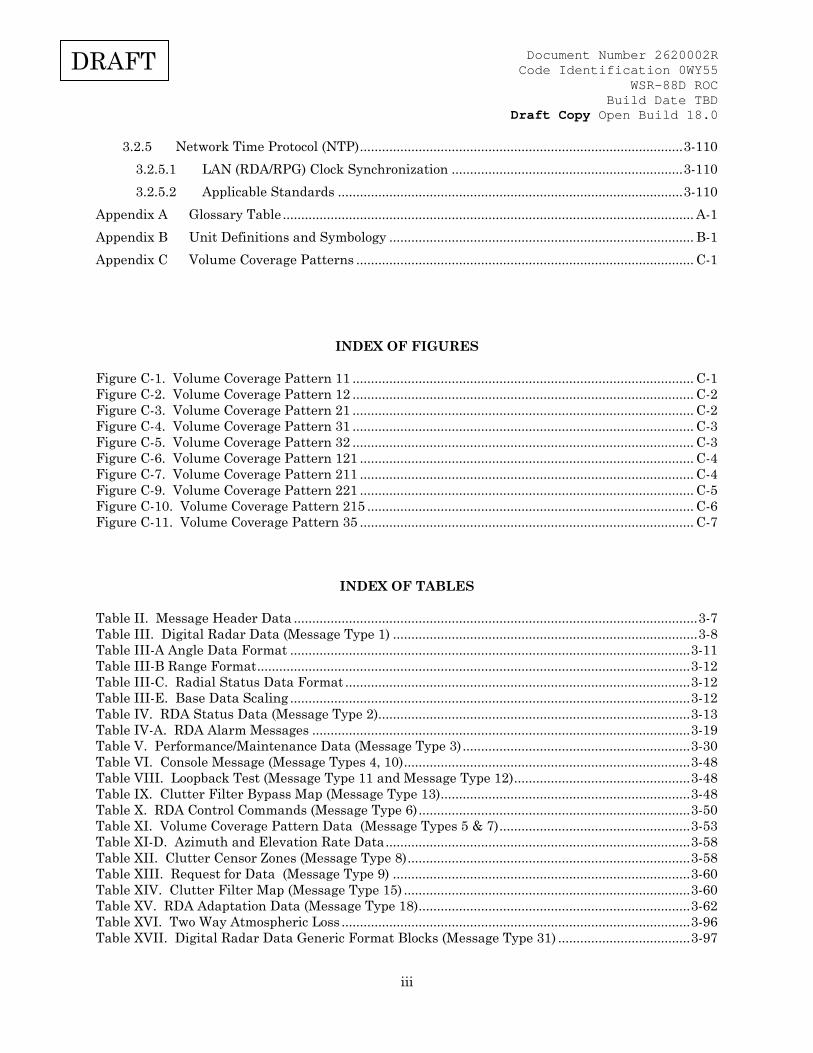
3.2.5 Network Time Protocol (NTP) ........................................................................................ 3-110 3.2.5.1 LAN (RDA/RPG) Clock Synchronization ............................................................... 3-110 3.2.5.2 Applicable Standards .............................................................................................. 3-110
Appendix A Glossary Table ................................................................................................................ A-1 Appendix B Unit Definitions and Symbology ................................................................................... B-1 Appendix C Volume Coverage Patterns ............................................................................................ C-1
INDEX OF FIGURES
Figure C-1. Volume Coverage Pattern 11 ............................................................................................. C-1 Figure C-2. Volume Coverage Pattern 12 ............................................................................................. C-2 Figure C-3. Volume Coverage Pattern 21 ............................................................................................. C-2 Figure C-4. Volume Coverage Pattern 31 ............................................................................................. C-3 Figure C-5. Volume Coverage Pattern 32 ............................................................................................. C-3 Figure C-6. Volume Coverage Pattern 121 ........................................................................................... C-4 Figure C-7. Volume Coverage Pattern 211 ........................................................................................... C-4 Figure C-9. Volume Coverage Pattern 221 ........................................................................................... C-5 Figure C-10. Volume Coverage Pattern 215 ......................................................................................... C-6 Figure C-11. Volume Coverage Pattern 35 ........................................................................................... C-7
INDEX OF TABLES
Table II. Message Header Data .............................................................................................................. 3-7 Table III. Digital Radar Data (Message Type 1) ................................................................................... 3-8 Table III-A Angle Data Format ............................................................................................................. 3-11 Table III-B Range Format ...................................................................................................................... 3-12 Table III-C. Radial Status Data Format .............................................................................................. 3-12 Table III-E. Base Data Scaling ............................................................................................................. 3-12 Table IV. RDA Status Data (Message Type 2) ..................................................................................... 3-13 Table IV-A. RDA Alarm Messages ....................................................................................................... 3-19 Table V. Performance/Maintenance Data (Message Type 3) .............................................................. 3-30 Table VI. Console Message (Message Types 4, 10) .............................................................................. 3-48 Table VIII. Loopback Test (Message Type 11 and Message Type 12) ................................................ 3-48 Table IX. Clutter Filter Bypass Map (Message Type 13) .................................................................... 3-48 Table X. RDA Control Commands (Message Type 6) .......................................................................... 3-50 Table XI. Volume Coverage Pattern Data (Message Types 5 & 7) .................................................... 3-53 Table XI-D. Azimuth and Elevation Rate Data ................................................................................... 3-58 Table XII. Clutter Censor Zones (Message Type 8) ............................................................................. 3-58 Table XIII. Request for Data (Message Type 9) ................................................................................. 3-60 Table XIV. Clutter Filter Map (Message Type 15) .............................................................................. 3-60 Table XV. RDA Adaptation Data (Message Type 18) .......................................................................... 3-62 Table XVI. Two Way Atmospheric Loss ............................................................................................... 3-96 Table XVII. Digital Radar Data Generic Format Blocks (Message Type 31) .................................... 3-97
Document Number 2620002R Code Identification 0WY55
WSR-88D ROC Build Date TBD
Draft Copy Open Build 18.0
iv
DRAFT
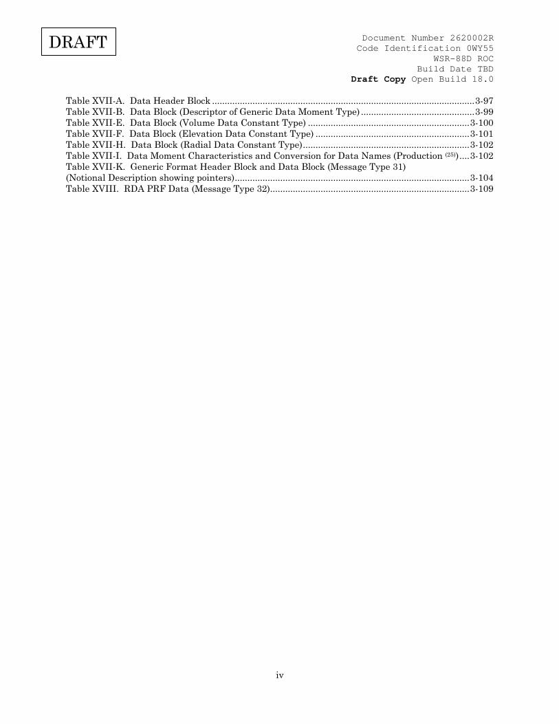
Table XVII-A. Data Header Block ........................................................................................................ 3-97 Table XVII-B. Data Block (Descriptor of Generic Data Moment Type) ............................................. 3-99 Table XVII-E. Data Block (Volume Data Constant Type) ................................................................ 3-100 Table XVII-F. Data Block (Elevation Data Constant Type) ............................................................. 3-101 Table XVII-H. Data Block (Radial Data Constant Type) .................................................................. 3-102 Table XVII-I. Data Moment Characteristics and Conversion for Data Names (Production (25)) .... 3-102 Table XVII-K. Generic Format Header Block and Data Block (Message Type 31) (Notional Description showing pointers) ............................................................................................. 3-104 Table XVIII. RDA PRF Data (Message Type 32) ............................................................................... 3-109
Document Number 2620002R Code Identification 0WY55
WSR-88D ROC Build Date TBD
Draft Copy Open Build 18.0
1-1
DRAFT
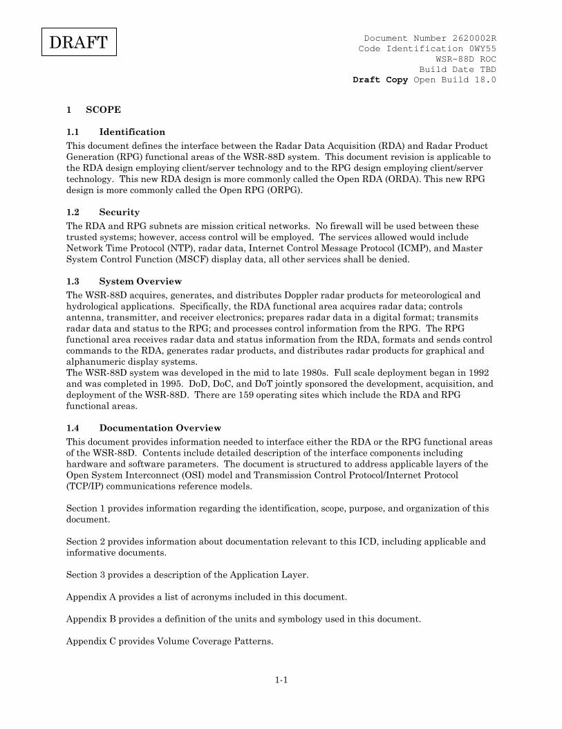
1 SCOPE
1.1 Identification This document defines the interface between the Radar Data Acquisition (RDA) and Radar Product Generation (RPG) functional areas of the WSR-88D system. This document revision is applicable to the RDA design employing client/server technology and to the RPG design employing client/server technology. This new RDA design is more commonly called the Open RDA (ORDA). This new RPG design is more commonly called the Open RPG (ORPG).
1.2 Security The RDA and RPG subnets are mission critical networks. No firewall will be used between these trusted systems; however, access control will be employed. The services allowed would include Network Time Protocol (NTP), radar data, Internet Control Message Protocol (ICMP), and Master System Control Function (MSCF) display data, all other services shall be denied.
1.3 System Overview The WSR-88D acquires, generates, and distributes Doppler radar products for meteorological and hydrological applications. Specifically, the RDA functional area acquires radar data; controls antenna, transmitter, and receiver electronics; prepares radar data in a digital format; transmits radar data and status to the RPG; and processes control information from the RPG. The RPG functional area receives radar data and status information from the RDA, formats and sends control commands to the RDA, generates radar products, and distributes radar products for graphical and alphanumeric display systems. The WSR-88D system was developed in the mid to late 1980s. Full scale deployment began in 1992 and was completed in 1995. DoD, DoC, and DoT jointly sponsored the development, acquisition, and deployment of the WSR-88D. There are 159 operating sites which include the RDA and RPG functional areas.
1.4 Documentation Overview This document provides information needed to interface either the RDA or the RPG functional areas of the WSR-88D. Contents include detailed description of the interface components including hardware and software parameters. The document is structured to address applicable layers of the Open System Interconnect (OSI) model and Transmission Control Protocol/Internet Protocol (TCP/IP) communications reference models. Section 1 provides information regarding the identification, scope, purpose, and organization of this document. Section 2 provides information about documentation relevant to this ICD, including applicable and informative documents. Section 3 provides a description of the Application Layer. Appendix A provides a list of acronyms included in this document. Appendix B provides a definition of the units and symbology used in this document. Appendix C provides Volume Coverage Patterns.

Document Number 2620002R Code Identification 0WY55
WSR-88D ROC Build Date TBD
Draft Copy Open Build 18.0
2-1
DRAFT
2 REFERENCE DOCUMENTS This section lists the number, title, revision, and date of all documents referenced in this specification. This section shall also identify the source for all documents not available through normal Government stocking activities.
2.1 Government Documents
2.1.1 Specifications Reference Number
Title
2810000F WSR-88D System Specification
2830013 WSR-88D System/Subsystem Design Document
2820001, Pt 1 Computer Program Development Specification for RDA Status and Control Program (CPCI-01)
2820003K, Pt1 Computer Program Development Specification for Radar Product Generation Program (SRS, CPCI-03)
2830006, Pt 1 Critical Item Development Specification for Wideband Communications Link (CI-06)
2620015A Microwave Line of Sight (MLOS) Fault Alarm System
2620036 RPG to Base Data Distribution Server (BDDS) ICD
2830007 Pt. 1 RPG Equipment B1 and update (CI-07) 2830009 Pt.1 RDA Equipment B1 (CI-09) 2620060 RDA/RPG TCP/IP ICD Source: WSR-88D Radar Operations Center
1313 Halley Circle Norman, OK 73069
2.2 Non-Government Documents
2.2.1 Industry Standards Reference Number Title IEEE 754-1985 IEEE Standard for Binary Floating-Point Arithmetic
Source: IEEE Customer Service
445 Hoes Lane PO Box.1331 Piscataway NJ 08855-1331 http://www.standards.ieee.org/

Document Number 2620002R Code Identification 0WY55
WSR-88D ROC Build Date TBD
Draft Copy Open Build 18.0
2-2
DRAFT
NIST Special Publication 330, 2001 Edition
The International System of Units (SI)
Source:
United States Department of Commerce National Institute of Standards and Technology http://physics.nist.gov

Document Number 2620002R Code Identification 0WY55
WSR-88D ROC Build Date TBD
Draft Copy Open Build 18.0
3-1
DRAFT
3 RDA TO RPG APPLICATION LAYER The applications messages associated with TCP/IP for the RPG to RDA interface are specified herein. The specific WSR-88D operating procedures and product message formats are defined also.
3.1 Session Specific
3.1.1 TCP Client/Server Relationship The TCP connection on the RPG side will be the client. The RDA connection will be the server.
3.1.2 TCP Port Mapping One TCP connection to the host is established and as a Permanent Virtual Channel (PVC).
3.1.3 General Message Descriptions All session messages have a three word integer header. All fields in the header are four octets in network (big endian) byte order. The first field (first four octets) of the header is the message type. The second field's function is message type dependent. The third field is the message size (number of octets of data following the header) excluding the message header. TCM Message Header
Message Type Message Type Dependent Server/Client Data Size
← 4 → octets
← 4 → octets
← 4 → octets
The following table contains the message types and message codes. Session Message Type Message Code LOGIN 0 LOGIN ACKNOWLEDGEMENT 1 DATA 2 DATA ACKNOWLEDGEMENT 3 KEEP ALIVE 4
3.1.4 Error Handling Either side of a session link will close and disconnect TCP connections for all PVCs on the detection of an error on any PVC. A disconnected client may attempt to reconnect at any time.
3.1.5 Disconnect To disconnect the RPG session, simply close TCP connections for all PVCs. The session layer is not established unless all PVCs for the link have valid TCP connections.
3.2 Application Specific
3.2.1 Data Formats The following data formats are referenced in this document: Code*1 One byte (8 bits) of integer data representing a bit field.
Code*2 Two bytes (16 bits) of integer data representing a bit field. Integer*1 One byte (8 bits) of unsigned integer data.
Document Number 2620002R Code Identification 0WY55
WSR-88D ROC Build Date TBD
Draft Copy Open Build 18.0
3-2
DRAFT
Integer*2 Two bytes (16 bits) of unsigned integer data.
Integer*4 Four bytes (32 bits) of unsigned integer data. Real*4 Four bytes (32 bits) of single precision floating point data in IEEE 754 format. Real*8 Eight bytes (64 bits) of double precision floating point data in IEEE 754 format. Scaled Integer*1
Floating point data represented by a 1-byte unsigned integer with an assumed decimal point whose position is defined by the precision of the item.
Scaled Integer*2
Floating point data represented by a 2-byte unsigned integer with an assumed decimal point whose position is defined by the precision of the item.
Scaled Integer*4
Floating point data represented by a 4-byte unsigned integer with an assumed decimal point whose position is defined by the precision of the item.
Scaled SInteger*2
Floating point data represented by a 2-byte signed integer with an assumed decimal point whose position is defined by the precision of the item.
Scaled SInteger*4
Floating point data represented by a 4-byte signed integer with an assumed decimal point whose position is defined by the precision of the item.
SInteger*1 One byte (8 bits) of integer data in standard 2's complement format.
SInteger*2 Two bytes (16 bits) of integer data in standard 2's complement format. SInteger*4 Four bytes (32 bits) of integer data in standard 2's complement format. String One or more 8-bit data items, each representing one ASCII character. Values that
do not take up the entire field size will be padded with NULL characters.
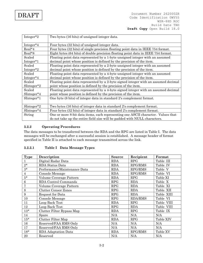
3.2.2 Operating Procedures The data messages to be transferred between the RDA and the RPG are listed in Table I. The data messages will be exchanged after a successful session is established. A message header of format specified in Table II is attached to each message transmitted across the link.
3.2.2.1 Table I Data Message Types
Type Description Source Recipient Format 1 Digital Radar Data RDA RPG Table III 2* RDA Status Data RDA RPG/RMS Table IV 3* Performance/Maintenance Data RDA RPG/RMS Table V 4 Console Message RDA RPG/RMS Table VI 5* Volume Coverage Pattern RDA RPG Table XI 6 RDA Control Commands RPG RDA Table X 7 Volume Coverage Pattern RPG RDA Table XI 8 Clutter Censor Zones RPG RDA Table XII 9 Request for Data RPG RDA Table XIII 10 Console Message RPG RDA/RMS Table VI 11 Loop Back Test RDA RPG Table VIII 12 Loop Back Test RPG RDA Table VIII 13* Clutter Filter Bypass Map RDA RPG Table IX 14 Spare N/A N/A N/A 15* Clutter Filter Map RDA RPG Table XIV 16 Reserved/FAA RMS Only N/A N/A N/A 17 Reserved/FAA RMS Only N/A N/A N/A 18* RDA Adaptation Data RDA RPG/RMS Table XV 20 Reserved N/A N/A N/A

Document Number 2620002R Code Identification 0WY55
WSR-88D ROC Build Date TBD
Draft Copy Open Build 18.0
3-3
DRAFT
21 Reserved N/A N/A N/A 22 Reserved N/A N/A N/A 23 Reserved N/A N/A N/A 24 Reserved/FAA RMS only N/A N/A N/A 25 Reserved/FAA RMS only N/A N/A N/A 26 Reserved/FAA RMS only N/A N/A N/A 29 Reserved N/A N/A N/A 31 Digital Radar Data Generic Format RDA RPG Table XVII 32 RDA PRF Data RDA RPG Table XVIII * = metadata
3.2.2.2 Messages from RDA Per Table I, data transmitted from the RDA to the RPG consists of Digital Radar Data (Message 1) or Digital Radar Data Generic Format (Message 31) plus RDA Status Data (Message 2), RDA Performance/Maintenance Data (Message 3), Console Messages (Message 4), Volume Coverage Pattern Data (Message 5), Loop Back Test (Message 11), Clutter Filter Bypass Map (Message 13), Clutter Filter Map (Message 15), RDA Adaptation Data (Message 18), and RDA PRF Data (Message 32). Digital Radar Data format is given in Table III, RDA Status Data format is given in Table IV, RDA Performance/Maintenance Data format is given in Table V, Console Message format is given in Table VI, Volume Coverage Pattern Data is given in Table XI, Loop Back Test format is given in Table VIII, Clutter Filter Bypass Map format is given in Table IX, Clutter Filter Map Data is given in table XIV, RDA Adaptation Data is given in Table XV, Digital Radar Data Generic Format is given in Table XVII, and RDA PRF Data format is given in Table XVIII. The RDA sends the ICD formatted message to the RPG. At the RPG end, the communications manager (RPG software task) inserts an additional 12 bytes to the ICD format message. The communications manager also inserts a communications manager header to the message, and then the message is sent to the RPG ingest application. This is also the same information, which is sent to the Base Data Distribution System (BDDS) processor.
3.2.2.2.1 Metadata Message Types and Purpose The capability to perform Level II recording has been moved from the RDA to the RPG. In order to continue to provide Metadata for Level II, the following Message Types need to be sent from the RDA to the RPG (see Table I) along with Message Type 1, Digital Radar Data or Message Type 31, Digital Radar Data Generic Format: 2 - RDA Status Data 3 - Performance/Maintenance Data 5 - Volume Coverage Pattern Data 13 - Clutter Filter Bypass Map Data 15 - Clutter Filter Map Data 18 - RDA Adaptation Data 32 - RDA PRF Data The RDA will send messages 2, 3, 5, 13, 15, 18, and 32 upon wideband connection and prior to going to "OPERATE" state. The RDA will send messages 2, 3 and 5 prior to sending message 1 (or 31) at the beginning of each VCP.
Document Number 2620002R Code Identification 0WY55
WSR-88D ROC Build Date TBD
Draft Copy Open Build 18.0
3-4
DRAFT
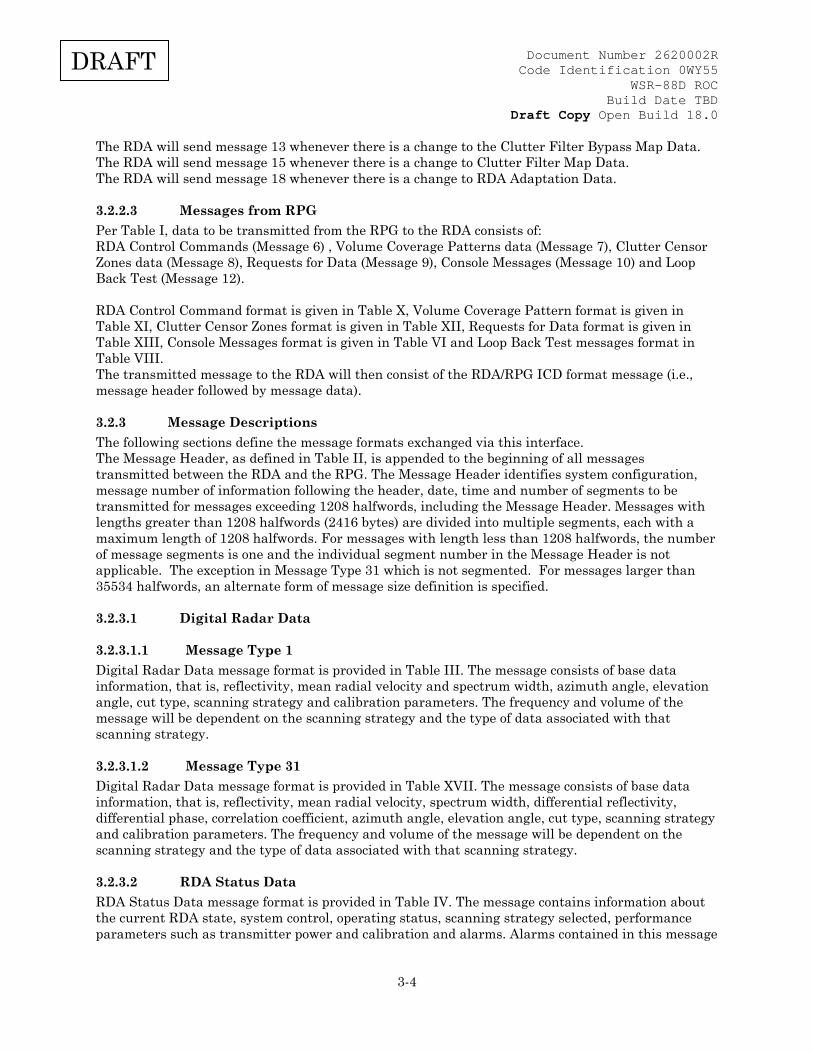
The RDA will send message 13 whenever there is a change to the Clutter Filter Bypass Map Data. The RDA will send message 15 whenever there is a change to Clutter Filter Map Data. The RDA will send message 18 whenever there is a change to RDA Adaptation Data.
3.2.2.3 Messages from RPG Per Table I, data to be transmitted from the RPG to the RDA consists of: RDA Control Commands (Message 6) , Volume Coverage Patterns data (Message 7), Clutter Censor Zones data (Message 8), Requests for Data (Message 9), Console Messages (Message 10) and Loop Back Test (Message 12). RDA Control Command format is given in Table X, Volume Coverage Pattern format is given in Table XI, Clutter Censor Zones format is given in Table XII, Requests for Data format is given in Table XIII, Console Messages format is given in Table VI and Loop Back Test messages format in Table VIII. The transmitted message to the RDA will then consist of the RDA/RPG ICD format message (i.e., message header followed by message data).
3.2.3 Message Descriptions The following sections define the message formats exchanged via this interface. The Message Header, as defined in Table II, is appended to the beginning of all messages transmitted between the RDA and the RPG. The Message Header identifies system configuration, message number of information following the header, date, time and number of segments to be transmitted for messages exceeding 1208 halfwords, including the Message Header. Messages with lengths greater than 1208 halfwords (2416 bytes) are divided into multiple segments, each with a maximum length of 1208 halfwords. For messages with length less than 1208 halfwords, the number of message segments is one and the individual segment number in the Message Header is not applicable. The exception in Message Type 31 which is not segmented. For messages larger than 35534 halfwords, an alternate form of message size definition is specified.
3.2.3.1 Digital Radar Data
3.2.3.1.1 Message Type 1 Digital Radar Data message format is provided in Table III. The message consists of base data information, that is, reflectivity, mean radial velocity and spectrum width, azimuth angle, elevation angle, cut type, scanning strategy and calibration parameters. The frequency and volume of the message will be dependent on the scanning strategy and the type of data associated with that scanning strategy.
3.2.3.1.2 Message Type 31 Digital Radar Data message format is provided in Table XVII. The message consists of base data information, that is, reflectivity, mean radial velocity, spectrum width, differential reflectivity, differential phase, correlation coefficient, azimuth angle, elevation angle, cut type, scanning strategy and calibration parameters. The frequency and volume of the message will be dependent on the scanning strategy and the type of data associated with that scanning strategy.
3.2.3.2 RDA Status Data RDA Status Data message format is provided in Table IV. The message contains information about the current RDA state, system control, operating status, scanning strategy selected, performance parameters such as transmitter power and calibration and alarms. Alarms contained in this message
Document Number 2620002R Code Identification 0WY55
WSR-88D ROC Build Date TBD
Draft Copy Open Build 18.0
3-5
DRAFT
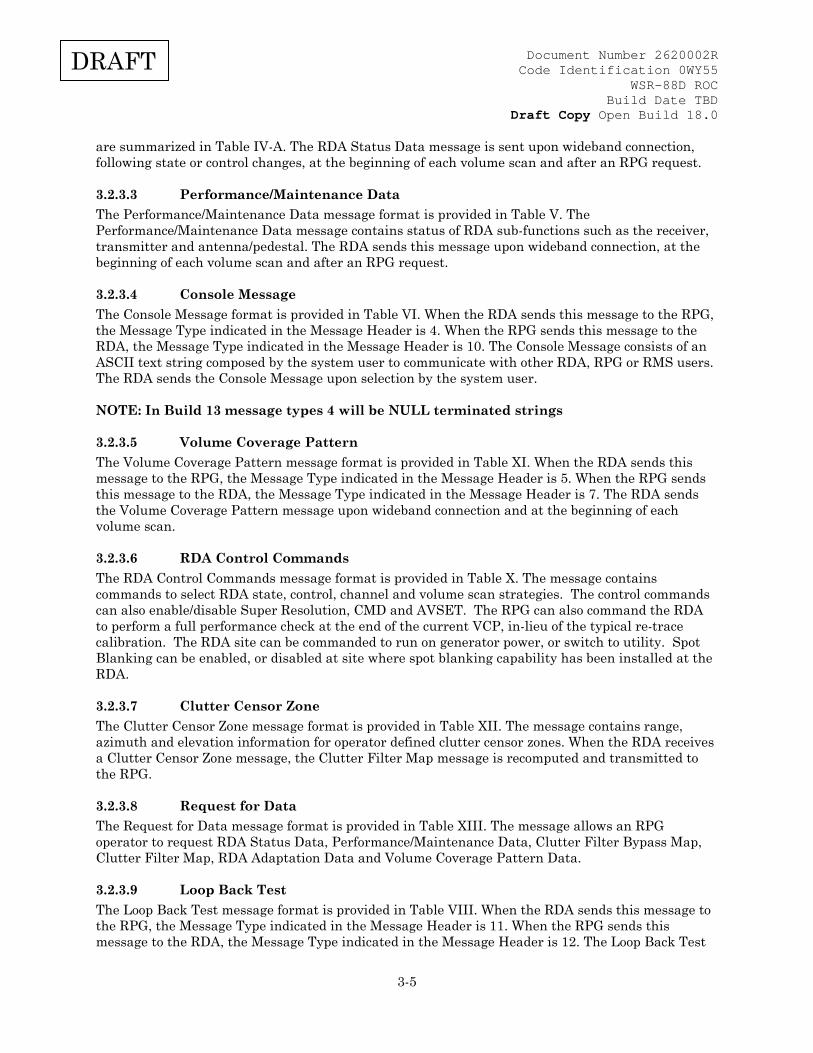
are summarized in Table IV-A. The RDA Status Data message is sent upon wideband connection, following state or control changes, at the beginning of each volume scan and after an RPG request.
3.2.3.3 Performance/Maintenance Data The Performance/Maintenance Data message format is provided in Table V. The Performance/Maintenance Data message contains status of RDA sub-functions such as the receiver, transmitter and antenna/pedestal. The RDA sends this message upon wideband connection, at the beginning of each volume scan and after an RPG request.
3.2.3.4 Console Message The Console Message format is provided in Table VI. When the RDA sends this message to the RPG, the Message Type indicated in the Message Header is 4. When the RPG sends this message to the RDA, the Message Type indicated in the Message Header is 10. The Console Message consists of an ASCII text string composed by the system user to communicate with other RDA, RPG or RMS users. The RDA sends the Console Message upon selection by the system user. NOTE: In Build 13 message types 4 will be NULL terminated strings
3.2.3.5 Volume Coverage Pattern The Volume Coverage Pattern message format is provided in Table XI. When the RDA sends this message to the RPG, the Message Type indicated in the Message Header is 5. When the RPG sends this message to the RDA, the Message Type indicated in the Message Header is 7. The RDA sends the Volume Coverage Pattern message upon wideband connection and at the beginning of each volume scan.
3.2.3.6 RDA Control Commands The RDA Control Commands message format is provided in Table X. The message contains commands to select RDA state, control, channel and volume scan strategies. The control commands can also enable/disable Super Resolution, CMD and AVSET. The RPG can also command the RDA to perform a full performance check at the end of the current VCP, in-lieu of the typical re-trace calibration. The RDA site can be commanded to run on generator power, or switch to utility. Spot Blanking can be enabled, or disabled at site where spot blanking capability has been installed at the RDA.
3.2.3.7 Clutter Censor Zone The Clutter Censor Zone message format is provided in Table XII. The message contains range, azimuth and elevation information for operator defined clutter censor zones. When the RDA receives a Clutter Censor Zone message, the Clutter Filter Map message is recomputed and transmitted to the RPG.
3.2.3.8 Request for Data The Request for Data message format is provided in Table XIII. The message allows an RPG operator to request RDA Status Data, Performance/Maintenance Data, Clutter Filter Bypass Map, Clutter Filter Map, RDA Adaptation Data and Volume Coverage Pattern Data.
3.2.3.9 Loop Back Test The Loop Back Test message format is provided in Table VIII. When the RDA sends this message to the RPG, the Message Type indicated in the Message Header is 11. When the RPG sends this message to the RDA, the Message Type indicated in the Message Header is 12. The Loop Back Test

Document Number 2620002R Code Identification 0WY55
WSR-88D ROC Build Date TBD
Draft Copy Open Build 18.0
3-6
DRAFT
message transmits a sequence of bit data to verify RDA to RPG communication. The RDA sends Message Type 11 to the RPG upon wideband connection. After receipt, the RPG re-sends Message Type 11 to the RDA without any modifications. The RPG sends Message Type 12 to the RDA upon wideband connection. After receipt, the RDA re-sends Message Type 12 to the RPG without any modifications.
3.2.3.10 Clutter Filter Bypass Map The Clutter Filter Bypass Map message format is provided in Table IX. The Clutter Filter Bypass Map contains information about which range bins are designated as clutter for the designated elevation segment and azimuth angle. When the RDA generates a new Clutter Filter Bypass Map, the Clutter Filter Bypass Map message is recomputed and transmitted to the RPG. When the Clutter Mitigation Decision system is enabled the Clutter Filter Bypass Map is updated every volume scan and transmitted during operational data collection.
3.2.3.11 Clutter Filter Map The Clutter Filter Map message format is provided in Table XIV. The Clutter Filter Map contains the clutter censor zone information formatted as in Table XIV. The RDA sends the Clutter Filter Map message upon wideband connection and whenever there is a change to the Clutter Filter Map.
3.2.3.12 Adaptation Data The Adaptation Data message format is provided in Table XV. The Adaptation Data message contains system parameters used by the RDA to determine alarm thresholds, signal processing parameters, and system configuration. The RDA sends the Adaptation Data message upon wideband connection and whenever there is a change to the data.
3.2.3.13 PRF Data The PRF Data message format is provided in Table XVIII. The PRF Data message contains the value of the PRFs used by the RDA for each type of Waveform, in millihertz. Waveform Type codes are the same as for the Volume Coverage Pattern message (Table XI). For example the surveillance code in "E3" of Table XI, would come from the given code value of the Surveillance waveform type. Similarly the Doppler code in E13, would be executed at the RDA as the same code number from the Doppler section of the PRF Data message.
3.2.4 Message Tables
Document Number 2620002R Code Identification 0WY55
WSR-88D ROC Build Date TBD
Draft Copy Open Build 18.0
3-7
DRAFT
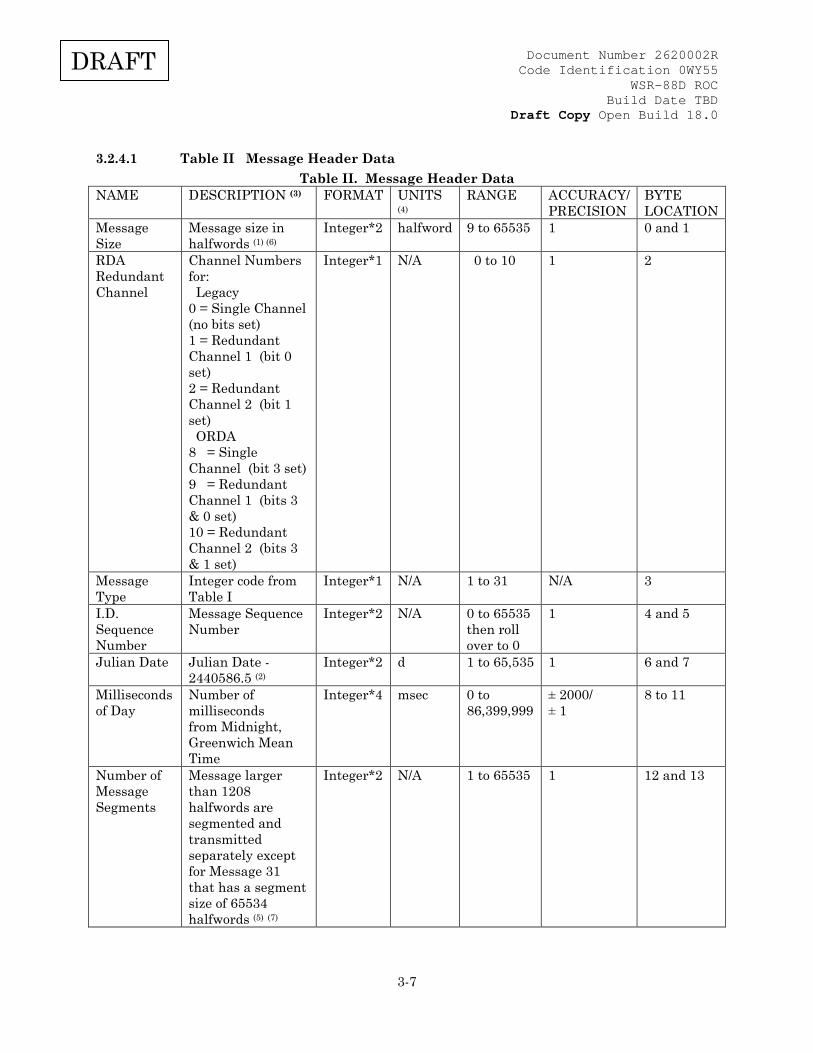
3.2.4.1 Table II Message Header Data Table II. Message Header Data
NAME DESCRIPTION (3) FORMAT UNITS
(4) RANGE ACCURACY/
PRECISION BYTE LOCATION
Message Size
Message size in halfwords (1) (6)
Integer*2 halfword 9 to 65535 1 0 and 1
RDA Redundant Channel
Channel Numbers for: Legacy 0 = Single Channel (no bits set) 1 = Redundant Channel 1 (bit 0 set) 2 = Redundant Channel 2 (bit 1 set) ORDA 8 = Single Channel (bit 3 set) 9 = Redundant Channel 1 (bits 3 & 0 set) 10 = Redundant Channel 2 (bits 3 & 1 set)
Integer*1 N/A 0 to 10 1 2
Message Type
Integer code from Table I
Integer*1 N/A 1 to 31 N/A 3
I.D. Sequence Number
Message Sequence Number
Integer*2 N/A 0 to 65535 then roll over to 0
1 4 and 5
Julian Date Julian Date - 2440586.5 (2)
Integer*2 d 1 to 65,535 1 6 and 7
Milliseconds of Day
Number of milliseconds from Midnight, Greenwich Mean Time
Integer*4 msec 0 to 86,399,999
± 2000/ ± 1
8 to 11
Number of Message Segments
Message larger than 1208 halfwords are segmented and transmitted separately except for Message 31 that has a segment size of 65534 halfwords (5) (7)
Integer*2 N/A 1 to 65535 1 12 and 13
Document Number 2620002R Code Identification 0WY55
WSR-88D ROC Build Date TBD
Draft Copy Open Build 18.0
3-8
DRAFT
NAME DESCRIPTION (3) FORMAT UNITS
(4) RANGE ACCURACY/
PRECISION BYTE LOCATION
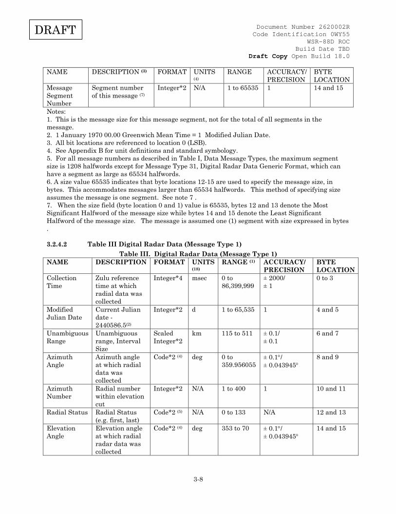
Message Segment Number
Segment number of this message (7)
Integer*2 N/A 1 to 65535 1 14 and 15
Notes: 1. This is the message size for this message segment, not for the total of all segments in the message. 2. 1 January 1970 00.00 Greenwich Mean Time = 1 Modified Julian Date. 3. All bit locations are referenced to location 0 (LSB). 4. See Appendix B for unit definitions and standard symbology. 5. For all message numbers as described in Table I, Data Message Types, the maximum segment size is 1208 halfwords except for Message Type 31, Digital Radar Data Generic Format, which can have a segment as large as 65534 halfwords. 6. A size value 65535 indicates that byte locations 12-15 are used to specify the message size, in bytes. This accommodates messages larger than 65534 halfwords. This method of specifying size assumes the message is one segment. See note 7 . 7. When the size field (byte location 0 and 1) value is 65535, bytes 12 and 13 denote the Most Significant Halfword of the message size while bytes 14 and 15 denote the Least Significant Halfword of the message size. The message is assumed one (1) segment with size expressed in bytes .
3.2.4.2 Table III Digital Radar Data (Message Type 1) Table III. Digital Radar Data (Message Type 1)
NAME DESCRIPTION FORMAT UNITS (18)
RANGE (1) ACCURACY/ PRECISION
BYTE LOCATION
Collection Time
Zulu reference time at which radial data was collected
Integer*4 msec 0 to 86,399,999
± 2000/ ± 1
0 to 3
Modified Julian Date
Current Julian date - 2440586.5(2)
Integer*2 d 1 to 65,535 1 4 and 5
Unambiguous Range
Unambiguous range, Interval Size
Scaled Integer*2
km 115 to 511 ± 0.1/ ± 0.1
6 and 7
Azimuth Angle
Azimuth angle at which radial data was collected
Code*2 (4) deg 0 to 359.956055
± 0.1°/ ± 0.043945°
8 and 9
Azimuth Number
Radial number within elevation cut
Integer*2 N/A 1 to 400 1 10 and 11
Radial Status Radial Status (e.g. first, last)
Code*2 (5) N/A 0 to 133 N/A 12 and 13
Elevation Angle
Elevation angle at which radial radar data was collected
Code*2 (4) deg 353 to 70 ± 0.1°/ ± 0.043945°
14 and 15

Document Number 2620002R Code Identification 0WY55
WSR-88D ROC Build Date TBD
Draft Copy Open Build 18.0
3-9
DRAFT
NAME DESCRIPTION FORMAT UNITS (18)
RANGE (1) ACCURACY/ PRECISION
BYTE LOCATION
Elevation Number
Elevation number within volume scan
Integer*2 N/A 1 to 25 1 16 and 17
Surveillance Range
Range to center of first surveillance gate (BIN)
Code*2 (7) km -32.768 to +32.767
± 0.05/ ± 0.001
18 and 19
Doppler Range
Range to center of first Doppler gate (BIN)
Code*2 (7) km -32.768 to +32.767
± 0.05/ ± 0.001
20 and 21
Surveillance Range Sample Interval
Size of surveillance sample interval
Code*2 (7) km 0.25 to 4 ± 0.05/ ± 0.001
22 and 23
Doppler Range Sample Interval
Size of Doppler Sample Interval
Code*2 (7) km 0.25 to 4 ± 0.05/ ± 0.001
24 and 25
Number of Surveillance Bins
Number of surveillance bins for current radial
Integer*2 N/A 0 to 460 1 26 and 27
Number of Doppler Bins
Number of Doppler bins for current radial
Integer*2 N/A 0 to 920 1 28 and 29
Cut Sector Number
Sector Number within cut
Integer*2 N/A 0 to 3(14)
1 30 and 31
Calibration Constant (dBZ0)
Scaling constant used by Signal Processor to calculate reflectivity
Real*4 dB -99.0 to +99.0
± 1/ N/A
32 to 35
Surveillance Pointer
Byte offset to surveillance data (15)
Integer*2 byte 100 (8) 1 36 and 37
Velocity Pointer
Byte offset to velocity data (15)
Integer*2 byte 100 to 560 (8)
1 38 and 39
Spectral Width Pointer
Byte offset to spectral width data (15)
Integer*2 byte 100 to 1480(8)
1 40 and 41
Doppler Velocity Resolution
Indicates scaling used for the Doppler Velocity
Code*2
N/A 2 = 0.5 m/s 4 = 1.0 m/s
N/A 42 and 43
Volume Coverage Pattern Number
Identifies Volume Coverage Pattern being used
Integer*2 N/A 1 to 767 1 44 and 45

Document Number 2620002R Code Identification 0WY55
WSR-88D ROC Build Date TBD
Draft Copy Open Build 18.0
3-10
DRAFT
NAME DESCRIPTION FORMAT UNITS (18)
RANGE (1) ACCURACY/ PRECISION
BYTE LOCATION
Spare Reserved for use by V + V Simulator (CPCI 24)
N/A N/A N/A N/A 46 to 53
Spare N/A N/A N/A N/A N/A 54 and 55 Spare N/A N/A N/A N/A N/A 56 and 57 Spare N/A N/A N/A N/A N/A 58 and 59 Nyquist Velocity
Nyquist Velocity Scaled Integer*2
m/s 8 to 35.61 (17)
± .003/ ± .01
60 and 61
ATMOS Atmospheric Attenuation Factor
Scaled Integer*2
dB/km −0.02 to −0.002
± .004/ ± .001
62 and 63
TOVER Threshold parameter which specifies the minimum difference in echo power between two resolution cells for them not to be labeled "overlayed"
Scaled Integer*2
dB 0.0 to 20.0 ± .1/ ± .1
64 and 65
Radial Spot Blanking Status
Spot blanking status for current radial, elevation cut and volume scan.
Integer*2 (9)
N/A 1=radial 2=elevation 4=volume
N/A 66 and 67
Spare N/A N/A N/A N/A N/A 68 to 99 Reflectivity Weather radar
surveillance data (0 to 460 Cells)
Code*1 (10)(11)
dBZ -32 to +94.5
± 1/ ± 0.5
100 to 559
Doppler Velocity
Weather radar velocity data (0 to 920 Cells)
Code*1 (10)(11)
m/s −63.5 to +63 −127 to +126
± 1/0.5 ± 1/1
100 to 1479 (12)
Doppler Spectrum Width
Weather radar spectral width data ( 0 to 920 Cells)
Code*1 (10)(11)
m/s -63.5 to +63
± 1/0.5 100 to 2399 (13)
Notes: 1. This field represents the range of the item after any applicable scaling and conversion is done. 2. 1 January 1970 00.00 GMT = 1 Modified Julian Date 4. Format Defined in Table III-A
Document Number 2620002R Code Identification 0WY55
WSR-88D ROC Build Date TBD
Draft Copy Open Build 18.0
3-11
DRAFT
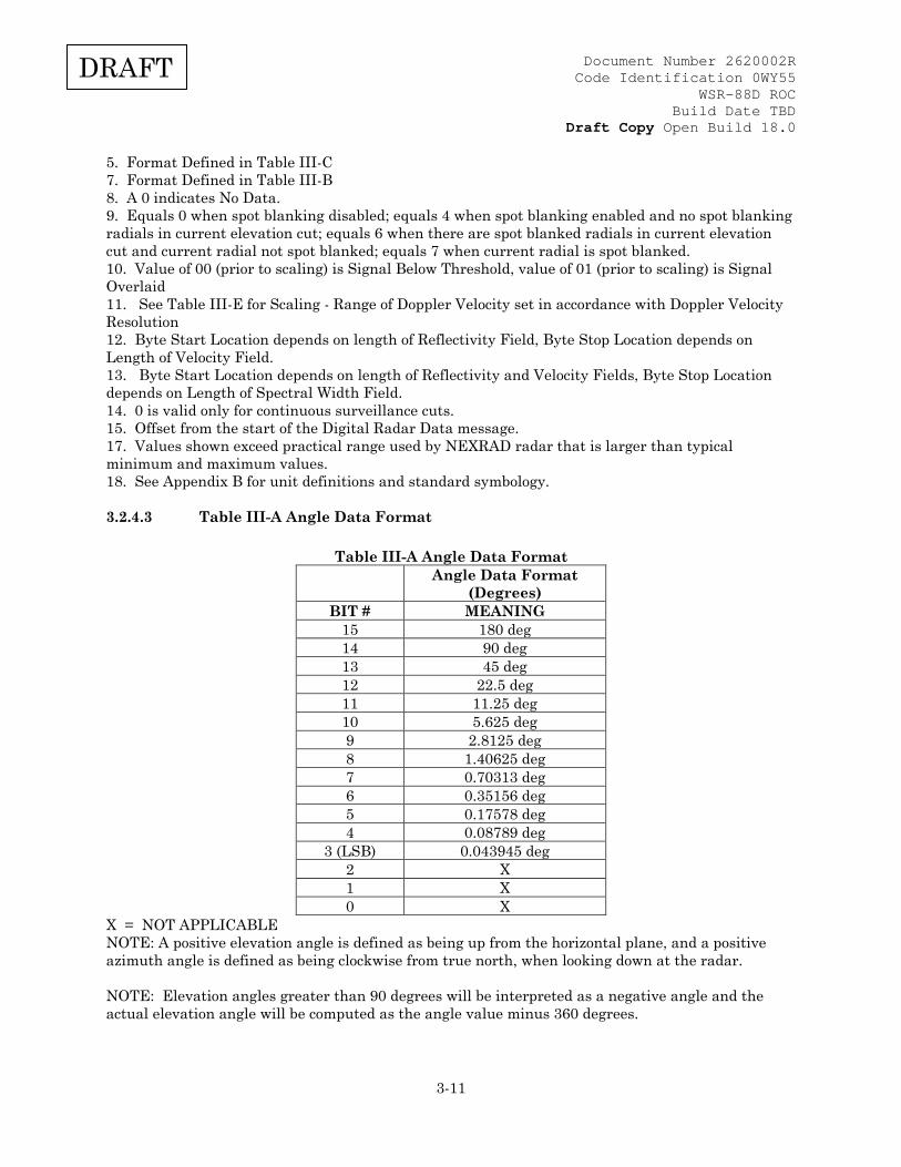
5. Format Defined in Table III-C 7. Format Defined in Table III-B 8. A 0 indicates No Data. 9. Equals 0 when spot blanking disabled; equals 4 when spot blanking enabled and no spot blanking radials in current elevation cut; equals 6 when there are spot blanked radials in current elevation cut and current radial not spot blanked; equals 7 when current radial is spot blanked. 10. Value of 00 (prior to scaling) is Signal Below Threshold, value of 01 (prior to scaling) is Signal Overlaid 11. See Table III-E for Scaling - Range of Doppler Velocity set in accordance with Doppler Velocity Resolution 12. Byte Start Location depends on length of Reflectivity Field, Byte Stop Location depends on Length of Velocity Field. 13. Byte Start Location depends on length of Reflectivity and Velocity Fields, Byte Stop Location depends on Length of Spectral Width Field. 14. 0 is valid only for continuous surveillance cuts. 15. Offset from the start of the Digital Radar Data message. 17. Values shown exceed practical range used by NEXRAD radar that is larger than typical minimum and maximum values. 18. See Appendix B for unit definitions and standard symbology.
3.2.4.3 Table III-A Angle Data Format
Table III-A Angle Data Format
Angle Data Format (Degrees)
BIT # MEANING 15 180 deg 14 90 deg 13 45 deg 12 22.5 deg 11 11.25 deg 10 5.625 deg 9 2.8125 deg 8 1.40625 deg 7 0.70313 deg 6 0.35156 deg 5 0.17578 deg 4 0.08789 deg
3 (LSB) 0.043945 deg 2 X 1 X 0 X
X = NOT APPLICABLE NOTE: A positive elevation angle is defined as being up from the horizontal plane, and a positive azimuth angle is defined as being clockwise from true north, when looking down at the radar. NOTE: Elevation angles greater than 90 degrees will be interpreted as a negative angle and the actual elevation angle will be computed as the angle value minus 360 degrees.
Document Number 2620002R Code Identification 0WY55
WSR-88D ROC Build Date TBD
Draft Copy Open Build 18.0
3-12
DRAFT
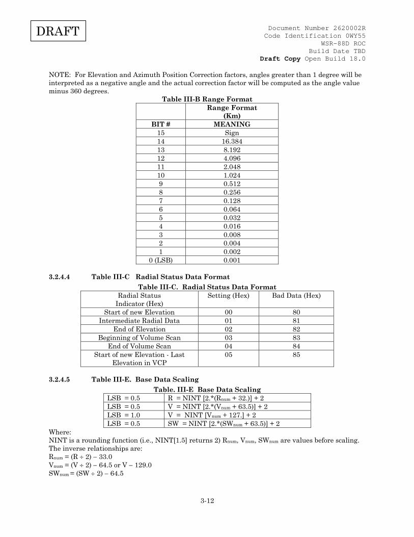
NOTE: For Elevation and Azimuth Position Correction factors, angles greater than 1 degree will be interpreted as a negative angle and the actual correction factor will be computed as the angle value minus 360 degrees.
Table III-B Range Format Range Format
(Km) BIT # MEANING
15 Sign 14 16.384 13 8.192 12 4.096 11 2.048 10 1.024 9 0.512 8 0.256 7 0.128 6 0.064 5 0.032 4 0.016 3 0.008 2 0.004 1 0.002
0 (LSB) 0.001
3.2.4.4 Table III-C Radial Status Data Format Table III-C. Radial Status Data Format
Radial Status Indicator (Hex)
Setting (Hex) Bad Data (Hex)
Start of new Elevation 00 80 Intermediate Radial Data 01 81
End of Elevation 02 82 Beginning of Volume Scan 03 83
End of Volume Scan 04 84 Start of new Elevation - Last
Elevation in VCP 05 85
3.2.4.5 Table III-E. Base Data Scaling Table. III-E Base Data Scaling
LSB = 0.5 R = NINT [2.*(Rnum + 32.)] + 2 LSB = 0.5 V = NINT [2.*(Vnum + 63.5)] + 2 LSB = 1.0 V = NINT [Vnum + 127.] + 2 LSB = 0.5 SW = NINT [2.*(SWnum + 63.5)] + 2
Where: NINT is a rounding function (i.e., NINT[1.5] returns 2) Rnum, Vnum, SWnum are values before scaling. The inverse relationships are: Rnum = (R ÷ 2) − 33.0 Vnum = (V ÷ 2) − 64.5 or V − 129.0 SWnum = (SW ÷ 2) − 64.5
Document Number 2620002R Code Identification 0WY55
WSR-88D ROC Build Date TBD
Draft Copy Open Build 18.0
3-13
DRAFT
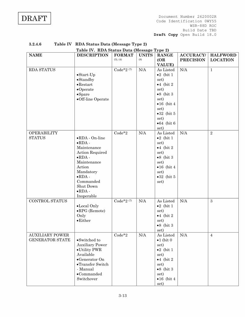
3.2.4.6 Table IV RDA Status Data (Message Type 2) Table IV. RDA Status Data (Message Type 2)
NAME DESCRIPTION FORMAT (3), (4)
UNITS (8)
RANGE (OR VALUE)
ACCURACY/ PRECISION
HALFWORD LOCATION
RDA STATUS •Start-Up •Standby •Restart •Operate •Spare •Off-line Operate
Code*2 (7) N/A As Listed •2 (bit 1 set) •4 (bit 2 set) •8 (bit 3 set) •16 (bit 4 set) •32 (bit 5 set) •64 (bit 6 set)
N/A 1
OPERABILITY STATUS
•RDA - On-line •RDA - Maintenance Action Required •RDA - Maintenance Action Mandatory •RDA - Commanded Shut Down •RDA - Inoperable
Code*2 N/A As Listed •2 (bit 1 set) •4 (bit 2 set) •8 (bit 3 set) •16 (bit 4 set) •32 (bit 5 set)
N/A 2
CONTROL STATUS •Local Only •RPG (Remote) Only •Either
Code*2 (7) N/A As Listed •2 (bit 1 set) •4 (bit 2 set) •8 (bit 3 set)
N/A 3
AUXILIARY POWER GENERATOR STATE
•Switched to Auxiliary Power •Utility PWR Available •Generator On •Transfer Switch - Manual •Commanded Switchover
Code*2 N/A As Listed •1 (bit 0 set) •2 (bit 1 set) •4 (bit 2 set) •8 (bit 3 set) •16 (bit 4 set)
N/A 4

Document Number 2620002R Code Identification 0WY55
WSR-88D ROC Build Date TBD
Draft Copy Open Build 18.0
3-14
DRAFT
NAME DESCRIPTION FORMAT (3), (4)
UNITS (8)
RANGE (OR VALUE)
ACCURACY/ PRECISION
HALFWORD LOCATION
AVERAGE TRANSMITTER POWER
Calculated over a range of samples
Integer*2 W 0 to 9999 ± 1/ ± 1
5
HORIZONTAL REFLECTIVITY CALIBRATION CORRECTION (delta dBZ0)
Difference from Adaptation Data
Scaled Integer*2
dB -198.00 to +198.00 (5)
1/0.01 6
DATA TRANSMISSION ENABLED
(Any combination of Data Enabled) •None •Reflectivity •Velocity •Width
Code*2 N/A As Listed •2 (bit 1 set) •4 (bit 2 set) •8 (bit 3 set) •16 (bit 4 set)
N/A 7
VOLUME COVERAGE PATTERN NUMBER
(Magnitude defines Pattern, Sign defines selection) •No Pattern •RDA Local Pattern Selected •RDA Remote Pattern Selected
SInteger*2 N/A As Listed •0 (no bits set) •Negative •Positive
1 8
RDA CONTROL AUTHORIZATION
•No Action •Local Control Requested •Remote Control Requested (a.k.a. Local Control Released)
Code*2 (7) N/A As Listed •0 (no bits set) •2 (bit 1 set) •4 (bit 2 set)
N/A 9
RDA BUILD NUMBER
RDA major & minor build version information
Scaled Integer*2
N/A 0 to 9999 (6)
N/A 10
OPERATIONAL MODE
•Operational •Maintenance
Code*2 (7) N/A As Listed •4 (bit 2 set) •8 (bit 3 set)
N/A 11
Document Number 2620002R Code Identification 0WY55
WSR-88D ROC Build Date TBD
Draft Copy Open Build 18.0
3-15
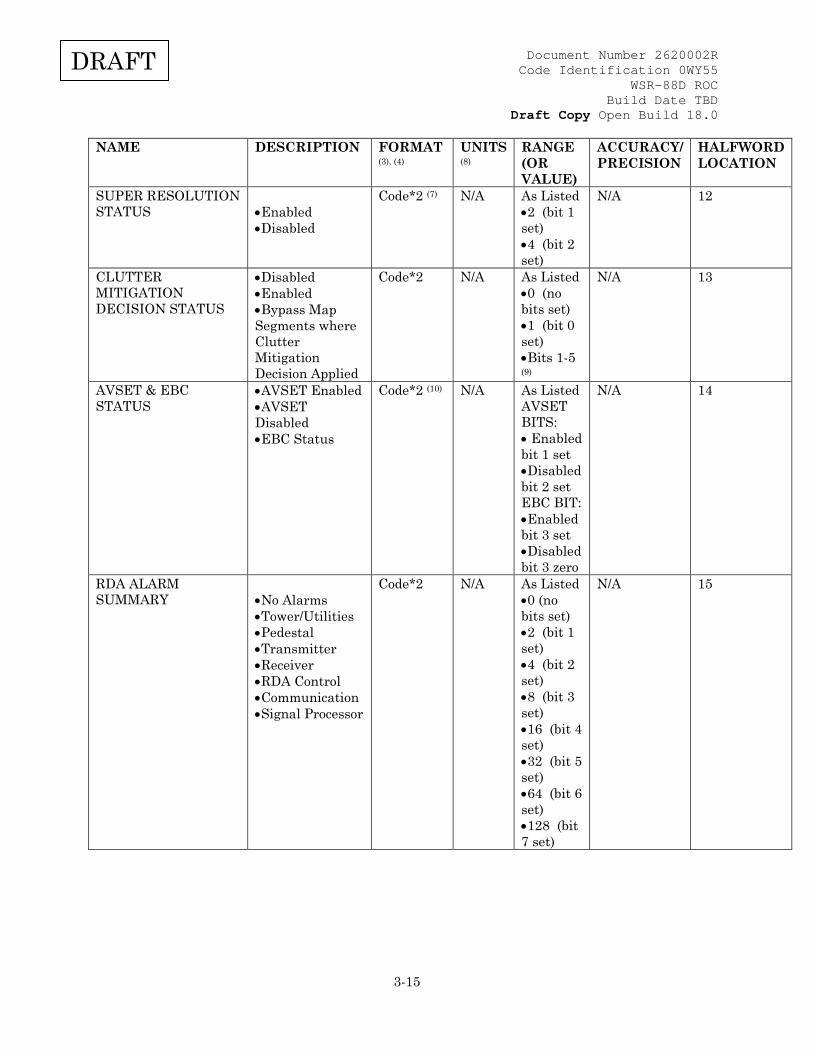
DRAFT
NAME DESCRIPTION FORMAT (3), (4)
UNITS (8)
RANGE (OR VALUE)
ACCURACY/ PRECISION
HALFWORD LOCATION
SUPER RESOLUTION STATUS
•Enabled •Disabled
Code*2 (7)
N/A As Listed
•2 (bit 1 set) •4 (bit 2 set)
N/A 12
CLUTTER MITIGATION DECISION STATUS
•Disabled •Enabled •Bypass Map Segments where Clutter Mitigation Decision Applied
Code*2 N/A As Listed •0 (no bits set) •1 (bit 0 set) •Bits 1-5 (9)
N/A 13
AVSET & EBC STATUS
•AVSET Enabled •AVSET Disabled •EBC Status
Code*2 (10) N/A As Listed AVSET BITS: • Enabled bit 1 set •Disabled bit 2 set EBC BIT: •Enabled bit 3 set •Disabled bit 3 zero
N/A 14
RDA ALARM SUMMARY
•No Alarms •Tower/Utilities •Pedestal •Transmitter •Receiver •RDA Control •Communication •Signal Processor
Code*2 N/A As Listed •0 (no bits set) •2 (bit 1 set) •4 (bit 2 set) •8 (bit 3 set) •16 (bit 4 set) •32 (bit 5 set) •64 (bit 6 set) •128 (bit 7 set)
N/A 15
Document Number 2620002R Code Identification 0WY55
WSR-88D ROC Build Date TBD
Draft Copy Open Build 18.0
3-16
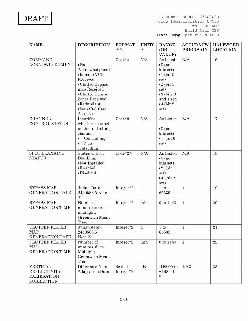
DRAFT
NAME DESCRIPTION FORMAT (3), (4)
UNITS (8)
RANGE (OR VALUE)
ACCURACY/ PRECISION
HALFWORD LOCATION
COMMAND ACKNOWLEDGMENT
•No Acknowledgment •Remote VCP Received •Clutter Bypass map Received •Clutter Censor Zones Received •Redundant Chan Ctrl Cmd Accepted
Code*2 N/A As listed •0 (no bits set) •1 (bit 0 set) •2 (bit 1 set) •3 (bits 0 and 1 set) •4 (bit 2 set)
N/A 16
CHANNEL CONTROL STATUS
Identifies whether channel is the controlling channel: • Controlling • Non-controlling
Code*2 N/A As Listed •0 (no bits set) •1 (bit 0 set)
N/A 17
SPOT BLANKING STATUS
Status of Spot Blanking: •Not Installed •Enabled •Disabled
Code*2 (7) N/A As Listed •0 (no bits set) •2 (bit 1 set) •4 (bit 2 set)
N/A 18
BYPASS MAP GENERATION DATE
Julian Date - 2440586.5 Note (1)
Integer*2 d 1 to 65535
1 19
BYPASS MAP GENERATION TIME
Number of minutes since midnight, Greenwich Mean Time
Integer*2 min 0 to 1440 1 20
CLUTTER FILTER MAP GENERATION DATE
Julian date - 2440586.5 Note (1)
Integer*2 d 1 to 65535
1 21
CLUTTER FILTER MAP GENERATION TIME
Number of minutes since Midnight, Greenwich Mean Time
Integer*2 min 0 to 1440 1 22
VERTICAL REFLECTIVITY CALIBRATION CORRECTION
Difference from Adaptation Data
Scaled Integer*2
dB -198.00 to +198.00 (5)
1/0.01 23

Document Number 2620002R Code Identification 0WY55
WSR-88D ROC Build Date TBD
Draft Copy Open Build 18.0
3-17
DRAFT
NAME DESCRIPTION FORMAT (3), (4)
UNITS (8)
RANGE (OR VALUE)
ACCURACY/ PRECISION
HALFWORD LOCATION
TRANSITION POWER SOURCE STATUS
Status of TPS: •Not Installed •OFF •OK
Integer*2 NA As Listed •0 (no bits set) •1 (bit 0 set) •3 (bits 0 and 1 set)
N/A 24
RMS CONTROL STATUS
Status of RMS Control: •NON-RMS SYSTEM •RMS IN CONTROL •RDA IN CONTROL
Code*2 (7) N/A As Listed •0 (no bits set) •2 (bit 1 set) •4 (bit 2 set)
N/A 25
PERFORMANCE CHECK STATUS
Status of Performance Check: NO COMMAND PENDING FORCE PERFORMANCE CHECK PENDING
Code*2 (7)
N/A As Listed •0 (no bits set) •1 (bit 0 set)
N/A 26
ALARM CODES One condition per halfword (Maximum of 14 alarms sent at a time). See Alarm Message Table IV-A for individual alarm codes. MSB set indicates alarm has been cleared.
Integer*2 N/A 0 to 800 N/A 27 to 40
SPARES SPARES FOR FUTURE USE
Integer*2 N/A N/A N/A 41 to 60
(1) January 1970 00.00 Greenwich Mean Time = 1 Modified Julian Date (3) All bit references start from 0 (LSB). (4) Unless otherwise indicated as mutually exclusive, Integer Code Formats can set multiple bits in the same message. For example, in case bits 1 and 2 are set, then the integer value passed would be 2 + 4 = 6. (5) The data in this field is stored as a scaled integer. The format is XXX.YY. For example, -198.00 equals a value of -19800. A value of +0.25 would equal a value of 25. (6) If value divided by 100 is greater than 2, then the Build Version is the value divided by 100. Otherwise, the Build Version is value divided by 10. (7) Values listed are mutually exclusive.
Document Number 2620002R Code Identification 0WY55
WSR-88D ROC Build Date TBD
Draft Copy Open Build 18.0
3-18
DRAFT
(8) See Appendix B for unit definitions and standard symbology. (9) Bits 1 through 5 represent elevation segments of the Bypass Map. Bit is set if the corresponding elevation segment has CMD applied. (10) Bits 1 and 2 are mutually exclusive and represent AVSET status. Bit 3 is EBC status.
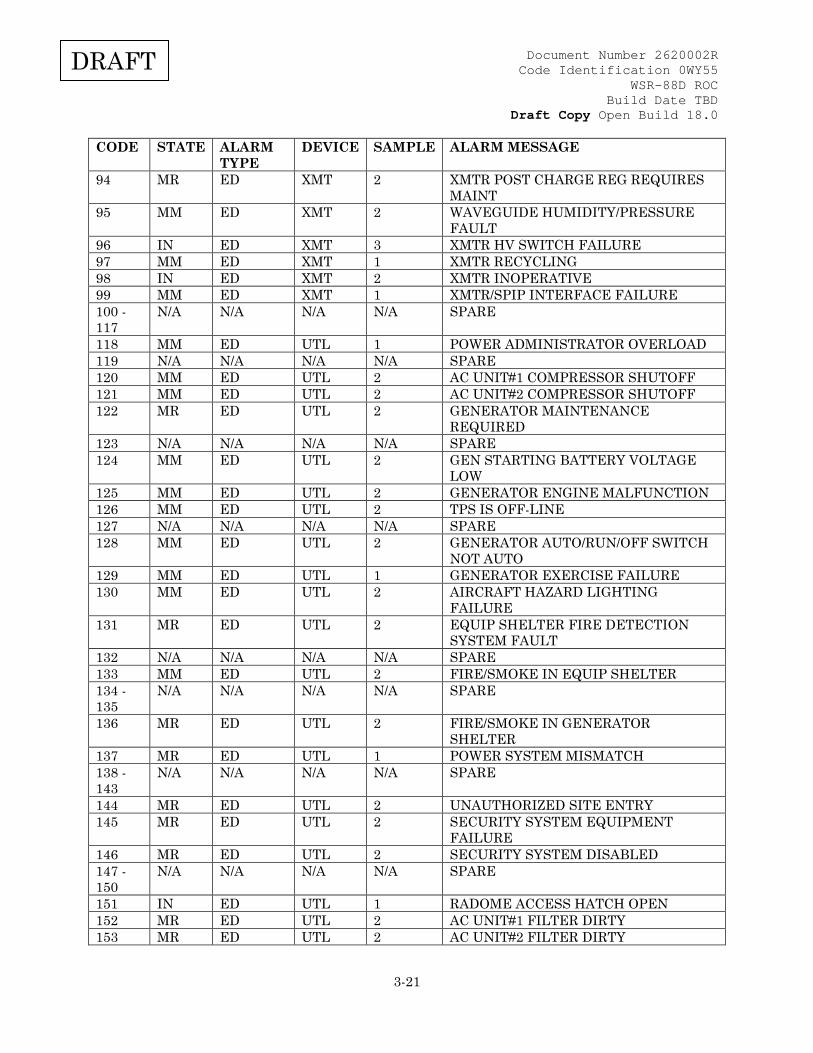
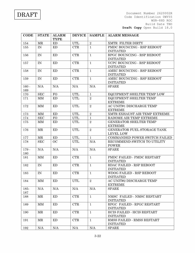
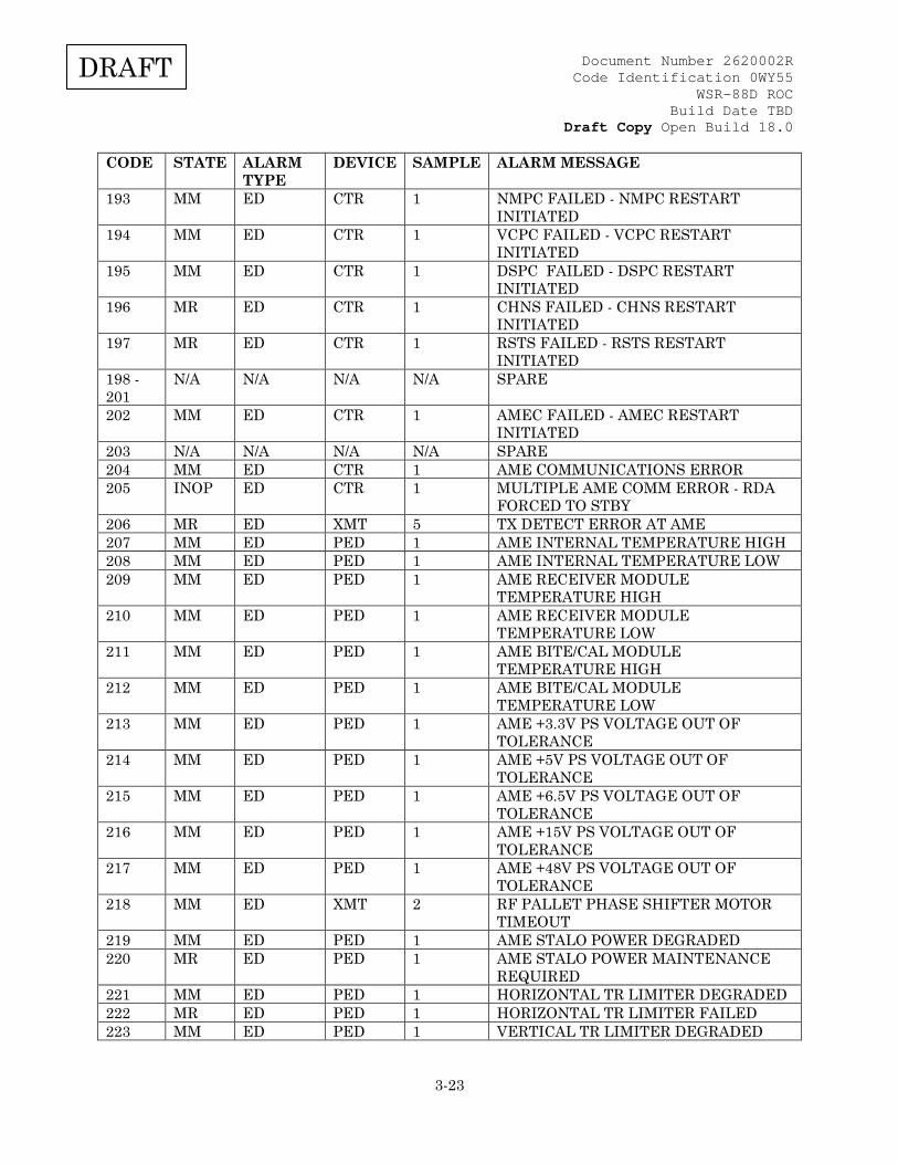
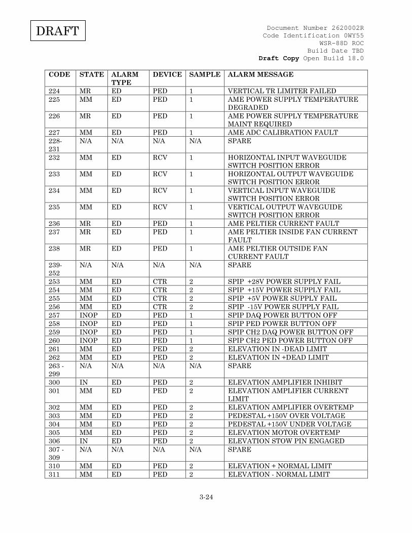
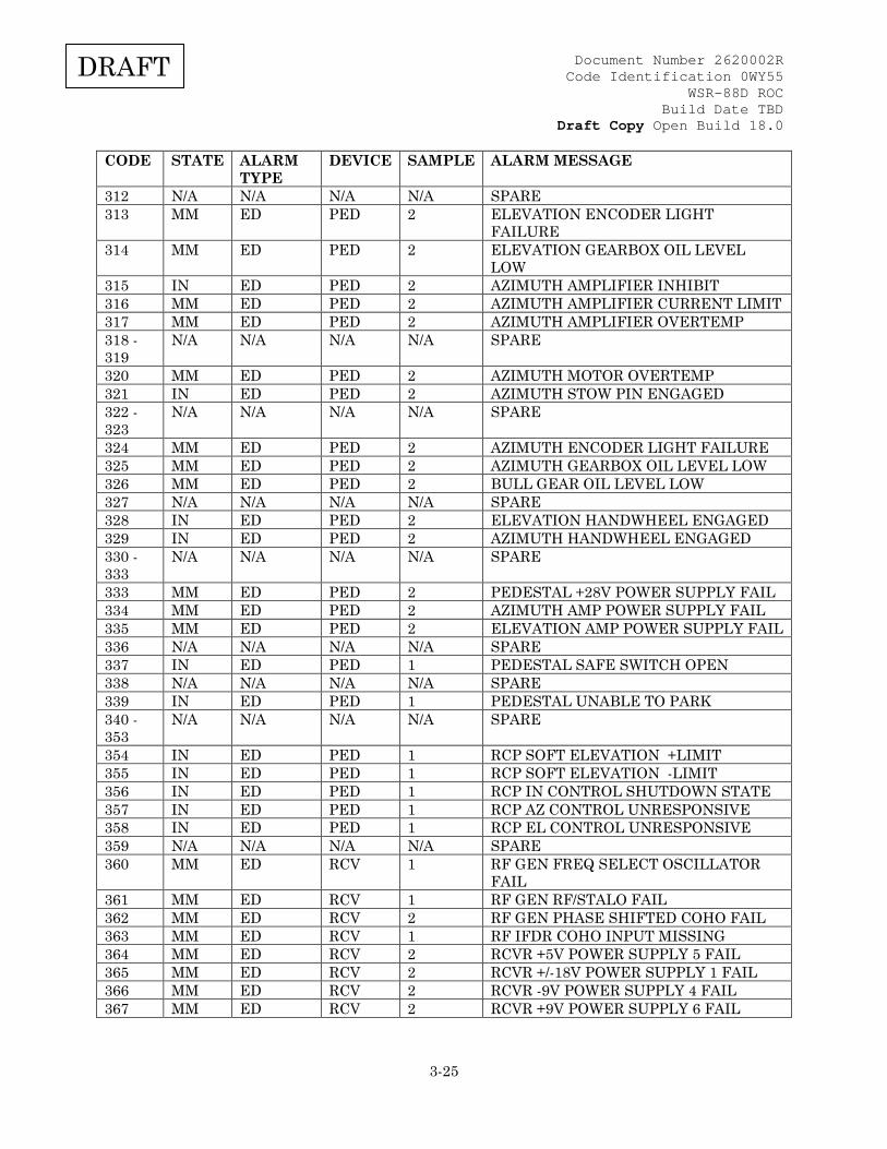
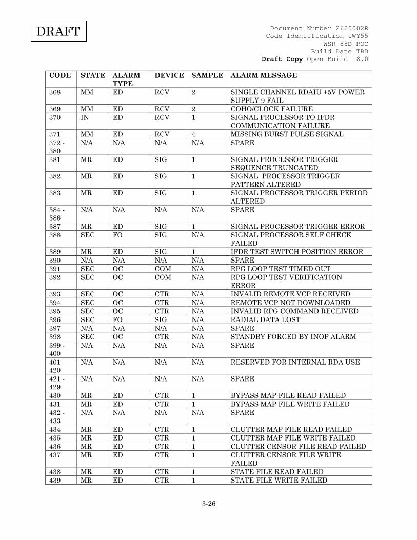
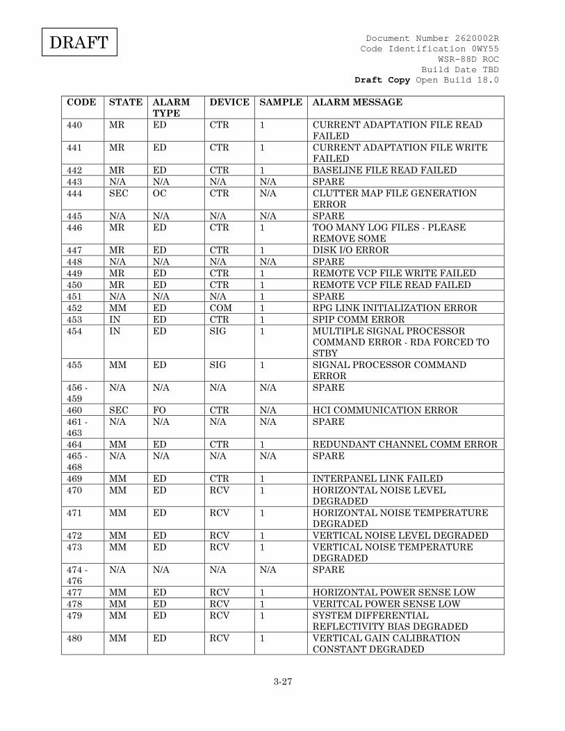
3.2.4.6.1 RDA Alarm Message Summary This following table summarizes alarms generated by the CPCI-01 Program. Alarms are grouped by functional areas. Each alarm is described as it is seen displayed in the alarm message on the RDA HCI and at the RPG. The "CODE" column is the unique alarm number given for identification purposes. The "STATE" column indicates the state of the RDA as a result of the alarm indicated: •MM = Maintenance Mandatory •MR = Maintenance Required •IN = Inoperative •SEC = Secondary (secondary alarms are not specifically tied to a "STATE" change). •N/A = Not applicable The "ALARM TYPE" column indicates that alarms are classified as three different alarm types based on how alarms are reported to the RDA. •ED - Alarms identified in the table as ED (Edge Detected) are reported every time the test associated with the alarm fails consecutively for a number of times equal to the alarm reporting count (see "Sample" column). Such alarms will be cleared (MSB set) when the test outcome first passes after the alarm is reported. •OC - Alarms identified in the table as OC (Occurrence) are reported each time the outcome of the associated test is FAILED. •FO - Alarms identified in the table as FO (Filtered Occurrence) are reported each time the outcome of the associated test is failed, but are not reported within 15 minutes of the last reporting. The "DEVICE" column indicates the hardware device area where the alarm has occurred (if applicable); acronyms under the DEVICE column are as follows: •CTR = Control •PED = Pedestal •RCV = Receiver •SIG = Signal Processor •COM = RDA Communications •UTL = Tower/Utilities •XMT= Transmitter The “SAMPLE” column indicates the number of samples (failures) that must occur before this alarm is displayed. The "ALARM MESSAGE" column is an abbreviated description of the alarm message that is displayed at both the RDA and RPG.

Document Number 2620002R Code Identification 0WY55
WSR-88D ROC Build Date TBD
Draft Copy Open Build 18.0
3-19
DRAFT
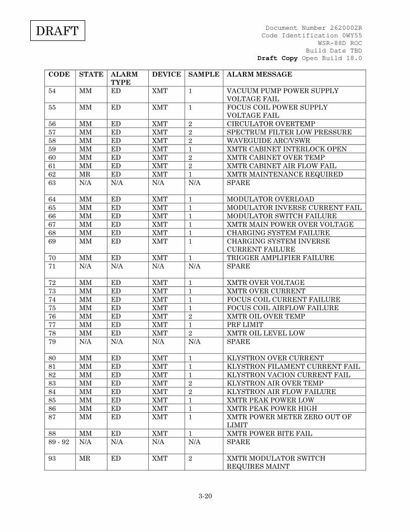
3.2.4.6.2 Table IV-A RDA Alarm Messages Table IV-A. RDA Alarm Messages
CODE STATE ALARM TYPE
DEVICE SAMPLE ALARM MESSAGE
0 N/A N/A N/A N/A NO ALARMS 1 N/A N/A N/A N/A RESERVED 2 N/A N/A N/A N/A RESERVED 3 - 13 N/A N/A N/A N/A SPARE 14 MR ED COM 1 ALTERNATE ROUTE TO RPG IN USE 15 MR ED COM 1 ALTERNATE ROUTE TO RPG IS DOWN 16 SEC FO COM N/A SEND WIDEBAND STATUS TIMED OUT 17 N/A N/A N/A N/A SPARE 18 N/A N/A N/A N/A SPARE 19 MR ED COM 1 GPS ANTENNA FAILURE 20 MM ED COM 1 RPG LINK - RED ALARM (NO RX) 21 MM ED COM 1 RPG LINK - YELLOW ALARM 22 MM ED COM 1 RPG LINK - BLUE ALARM 23 MM ED COM 1 RDA CSU FAILURE 24 MR ED COM 2 SNMP TIME OUT: LAN SWITCH 25 MR ED COM 2 SNMP TIME OUT: ROUTER 26 N/A N/A N/A N/A SPARE 27 MR ED COM 2 SNMP TIME OUT: POWER
ADMINISTRATOR 28 MR ED COM 2 SNMP TIME OUT: GPS 29 N/A N/A N/A N/A SPARE 30 MR ED COM 2 SNMP TIME OUT: CONSOLE SERVER 31 MR ED COM 1 LAN SWITCH PORT 1 FAIL 32 N/A N/A N/A N/A SPARE 33 MR ED COM 1 LAN SWITCH PORT 3 FAIL 34 N/A N/A N/A N/A SPARE 35 MR ED COM 1 LAN SWITCH PORT 5 FAIL 36 MR ED COM 1 LAN SWITCH PORT 7 FAIL 37 MR ED COM 1 LAN SWITCH PORT 12 FAIL 38-39 N/A N/A N/A N/A SPARE 40 IN ED XMT 2 FILAMENT POWER SUPPLY OFF 41-42 N/A N/A N/A N/A SPARE 43 IN ED XMT 3 WAVEGUIDE SWITCH FAILURE 44 IN ED XMT 2 WAVEGUIDE/PFN TRANSFER
INTERLOCK 45 IN ED XMT 2 XMTR IN MAINTENANCE MODE 46 IN ED XMT 2 XMTR UNAVAILABLE 47 IN ED XMT 3 PFN/PW SWITCH FAILURE 48 MM ED XMT 2 XMTR +5VDC POWER SUPPLY 6 FAIL 49 MM ED XMT 2 XMTR +15VDC POWER SUPPLY 4 FAIL 50 MM ED XMT 2 XMTR +28VDC POWER SUPPLY 3 FAIL 51 MM ED XMT 2 XMTR -15VDC POWER SUPPLY 5 FAIL 52 MM ED XMT 2 XMTR +45VDC POWER SUPPLY 7 FAIL 53 MM ED XMT 1 FILAMENT POWER SUPPLY VOLTAGE
FAIL
Document Number 2620002R Code Identification 0WY55
WSR-88D ROC Build Date TBD
Draft Copy Open Build 18.0
3-20
DRAFT
CODE STATE ALARM TYPE
DEVICE SAMPLE ALARM MESSAGE
54 MM ED XMT 1 VACUUM PUMP POWER SUPPLY VOLTAGE FAIL
55 MM ED XMT 1 FOCUS COIL POWER SUPPLY VOLTAGE FAIL
56 MM ED XMT 2 CIRCULATOR OVERTEMP 57 MM ED XMT 2 SPECTRUM FILTER LOW PRESSURE 58 MM ED XMT 2 WAVEGUIDE ARC/VSWR 59 MM ED XMT 1 XMTR CABINET INTERLOCK OPEN 60 MM ED XMT 2 XMTR CABINET OVER TEMP 61 MM ED XMT 2 XMTR CABINET AIR FLOW FAIL 62 MR ED XMT 1 XMTR MAINTENANCE REQUIRED 63 N/A N/A N/A N/A
SPARE
64 MM ED XMT 1 MODULATOR OVERLOAD 65 MM ED XMT 1 MODULATOR INVERSE CURRENT FAIL 66 MM ED XMT 1 MODULATOR SWITCH FAILURE 67 MM ED XMT 1 XMTR MAIN POWER OVER VOLTAGE 68 MM ED XMT 1 CHARGING SYSTEM FAILURE 69 MM ED XMT 1 CHARGING SYSTEM INVERSE
CURRENT FAILURE 70 MM ED XMT 1 TRIGGER AMPLIFIER FAILURE 71 N/A N/A N/A N/A
SPARE
72 MM ED XMT 1 XMTR OVER VOLTAGE 73 MM ED XMT 1 XMTR OVER CURRENT 74 MM ED XMT 1 FOCUS COIL CURRENT FAILURE 75 MM ED XMT 1 FOCUS COIL AIRFLOW FAILURE 76 MM ED XMT 2 XMTR OIL OVER TEMP 77 MM ED XMT 1 PRF LIMIT 78 MM ED XMT 2 XMTR OIL LEVEL LOW 79 N/A N/A N/A N/A
SPARE
80 MM ED XMT 1 KLYSTRON OVER CURRENT 81 MM ED XMT 1 KLYSTRON FILAMENT CURRENT FAIL 82 MM ED XMT 1 KLYSTRON VACION CURRENT FAIL 83 MM ED XMT 2 KLYSTRON AIR OVER TEMP 84 MM ED XMT 2 KLYSTRON AIR FLOW FAILURE 85 MM ED XMT 1 XMTR PEAK POWER LOW 86 MM ED XMT 1 XMTR PEAK POWER HIGH 87 MM ED XMT 1 XMTR POWER METER ZERO OUT OF
LIMIT 88 MM ED XMT 1 XMTR POWER BITE FAIL 89 - 92 N/A N/A N/A N/A
SPARE
93 MR ED XMT 2 XMTR MODULATOR SWITCH REQUIRES MAINT
Document Number 2620002R Code Identification 0WY55
WSR-88D ROC Build Date TBD
Draft Copy Open Build 18.0
3-21
DRAFT
CODE STATE ALARM TYPE
DEVICE SAMPLE ALARM MESSAGE
94 MR ED XMT 2 XMTR POST CHARGE REG REQUIRES MAINT
95 MM ED XMT 2 WAVEGUIDE HUMIDITY/PRESSURE FAULT
96 IN ED XMT 3 XMTR HV SWITCH FAILURE 97 MM ED XMT 1 XMTR RECYCLING 98 IN ED XMT 2 XMTR INOPERATIVE 99 MM ED XMT 1 XMTR/SPIP INTERFACE FAILURE 100 - 117
N/A N/A N/A N/A
SPARE
118 MM ED UTL 1 POWER ADMINISTRATOR OVERLOAD 119 N/A N/A N/A N/A SPARE 120 MM ED UTL 2 AC UNIT#1 COMPRESSOR SHUTOFF 121 MM ED UTL 2 AC UNIT#2 COMPRESSOR SHUTOFF 122 MR ED UTL 2 GENERATOR MAINTENANCE
REQUIRED 123 N/A N/A N/A N/A SPARE 124 MM ED UTL 2 GEN STARTING BATTERY VOLTAGE
LOW 125 MM ED UTL 2 GENERATOR ENGINE MALFUNCTION 126 MM ED UTL 2 TPS IS OFF-LINE 127 N/A N/A N/A N/A SPARE 128 MM ED UTL 2 GENERATOR AUTO/RUN/OFF SWITCH
NOT AUTO 129 MM ED UTL 1 GENERATOR EXERCISE FAILURE 130 MM ED UTL 2 AIRCRAFT HAZARD LIGHTING
FAILURE 131 MR ED UTL 2 EQUIP SHELTER FIRE DETECTION
SYSTEM FAULT 132 N/A N/A N/A N/A SPARE 133 MM ED UTL 2 FIRE/SMOKE IN EQUIP SHELTER 134 - 135
N/A N/A N/A N/A SPARE
136 MR ED UTL 2 FIRE/SMOKE IN GENERATOR SHELTER
137 MR ED UTL 1 POWER SYSTEM MISMATCH 138 - 143
N/A N/A N/A N/A SPARE
144 MR ED UTL 2 UNAUTHORIZED SITE ENTRY 145 MR ED UTL 2 SECURITY SYSTEM EQUIPMENT
FAILURE 146 MR ED UTL 2 SECURITY SYSTEM DISABLED 147 - 150
N/A N/A N/A N/A SPARE
151 IN ED UTL 1 RADOME ACCESS HATCH OPEN 152 MR ED UTL 2 AC UNIT#1 FILTER DIRTY 153 MR ED UTL 2 AC UNIT#2 FILTER DIRTY
Document Number 2620002R Code Identification 0WY55
WSR-88D ROC Build Date TBD
Draft Copy Open Build 18.0
3-22
DRAFT
CODE STATE ALARM TYPE
DEVICE SAMPLE ALARM MESSAGE
154 MR ED UTL 2 XMTR FILTER DIRTY 155 IN ED CTR 1 PMDC BOUNCING - RSP REBOOT
INITIATED 156 IN ED CTR 1 RPGC BOUNCING - RSP REBOOT
INITIATED 157 IN ED CTR 1 VCPC BOUNCING - RSP REBOOT
INITIATED 158 IN ED CTR 1 AMEC BOUNCING - RSP REBOOT
INITIATED 159 IN ED CTR 1 AMEC BOUNCING - RSP REBOOT
INITIATED 160 - 169
N/A N/A N/A N/A SPARE
170 SEC FO UTL 1 EQUIPMENT SHELTER TEMP LOW 171 MM ED UTL 2 EQUIPMENT SHELTER TEMP
EXTREME 172 MM ED UTL 2 AC UNIT#1 DISCHARGE TEMP
EXTREME 173 MM ED UTL 2 XMTR EXHAUST AIR TEMP EXTREME 174 SEC FO UTL 1 RADOME AIR TEMP EXTREME 175 MM ED UTL 2 GENERATOR SHELTER TEMP
EXTREME 176 MR ED UTL 2 GENERATOR FUEL STORAGE TANK
LEVEL LOW 177 MR ED UTL 1 COMMANDED POWER SWITCH FAILED 178 SEC OC UTL N/A RECOMMEND SWITCH TO UTILITY
POWER 179 - 180
N/A N/A N/A N/A SPARE
181 MM ED CTR 1 PMDC FAILED - PMDC RESTART INITIATED
182 IN ED CTR 1 RDAC FAILED - RSP REBOOT INITIATED
183 IN ED CTR 1 WDOG FAILED - RSP REBOOT INITIATED
184 MM ED UTL 2 AC UNIT#2 DISCHARGE TEMP EXTREME
185-187
N/A N/A N/A N/A SPARE
188 MR ED CTR 1 NMSC FAILED - NMSC RESTART INITIATED
189 MM ED CTR 1 RPGC FAILED - RPGC RESTART INITIATED
190 MR ED CTR 1 HCIS FAILED - HCIS RESTART INITIATED
191 MR ED CTR 1 RMSS FAILED - RMSS RESTART INITIATED
192 N/A N/A N/A N/A SPARE
Document Number 2620002R Code Identification 0WY55
WSR-88D ROC Build Date TBD
Draft Copy Open Build 18.0
3-23
DRAFT
CODE STATE ALARM TYPE
DEVICE SAMPLE ALARM MESSAGE
193 MM ED CTR 1 NMPC FAILED - NMPC RESTART INITIATED
194 MM ED CTR 1 VCPC FAILED - VCPC RESTART INITIATED
195 MM ED CTR 1 DSPC FAILED - DSPC RESTART INITIATED
196 MR ED CTR 1 CHNS FAILED - CHNS RESTART INITIATED
197 MR ED CTR 1 RSTS FAILED - RSTS RESTART INITIATED
198 - 201
N/A N/A N/A N/A SPARE
202 MM ED CTR 1 AMEC FAILED - AMEC RESTART INITIATED
203 N/A N/A N/A N/A SPARE 204 MM ED CTR 1 AME COMMUNICATIONS ERROR 205 INOP ED CTR 1 MULTIPLE AME COMM ERROR - RDA
FORCED TO STBY 206 MR ED XMT 5 TX DETECT ERROR AT AME 207 MM ED PED 1 AME INTERNAL TEMPERATURE HIGH 208 MM ED PED 1 AME INTERNAL TEMPERATURE LOW 209 MM ED PED 1 AME RECEIVER MODULE
TEMPERATURE HIGH 210 MM ED PED 1 AME RECEIVER MODULE
TEMPERATURE LOW 211 MM ED PED 1 AME BITE/CAL MODULE
TEMPERATURE HIGH 212 MM ED PED 1 AME BITE/CAL MODULE
TEMPERATURE LOW 213 MM ED PED 1 AME +3.3V PS VOLTAGE OUT OF
TOLERANCE 214 MM ED PED 1 AME +5V PS VOLTAGE OUT OF
TOLERANCE 215 MM ED PED 1 AME +6.5V PS VOLTAGE OUT OF
TOLERANCE 216 MM ED PED 1 AME +15V PS VOLTAGE OUT OF
TOLERANCE 217 MM ED PED 1 AME +48V PS VOLTAGE OUT OF
TOLERANCE 218 MM ED XMT 2 RF PALLET PHASE SHIFTER MOTOR
TIMEOUT 219 MM ED PED 1 AME STALO POWER DEGRADED 220 MR ED PED 1 AME STALO POWER MAINTENANCE
REQUIRED 221 MM ED PED 1 HORIZONTAL TR LIMITER DEGRADED 222 MR ED PED 1 HORIZONTAL TR LIMITER FAILED 223 MM ED PED 1 VERTICAL TR LIMITER DEGRADED
Document Number 2620002R Code Identification 0WY55
WSR-88D ROC Build Date TBD
Draft Copy Open Build 18.0
3-24
DRAFT
CODE STATE ALARM TYPE
DEVICE SAMPLE ALARM MESSAGE
224 MR ED PED 1 VERTICAL TR LIMITER FAILED 225 MM ED PED 1 AME POWER SUPPLY TEMPERATURE
DEGRADED 226 MR ED PED 1 AME POWER SUPPLY TEMPERATURE
MAINT REQUIRED 227 MM ED PED 1 AME ADC CALIBRATION FAULT 228-231
N/A N/A N/A N/A SPARE
232 MM ED RCV 1 HORIZONTAL INPUT WAVEGUIDE SWITCH POSITION ERROR
233 MM ED RCV 1 HORIZONTAL OUTPUT WAVEGUIDE SWITCH POSITION ERROR
234 MM ED RCV 1 VERTICAL INPUT WAVEGUIDE SWITCH POSITION ERROR
235 MM ED RCV 1 VERTICAL OUTPUT WAVEGUIDE SWITCH POSITION ERROR
236 MR ED PED 1 AME PELTIER CURRENT FAULT 237 MR ED PED 1 AME PELTIER INSIDE FAN CURRENT
FAULT 238 MR ED PED 1 AME PELTIER OUTSIDE FAN
CURRENT FAULT 239-252
N/A N/A N/A N/A SPARE
253 MM ED CTR 2 SPIP +28V POWER SUPPLY FAIL 254 MM ED CTR 2 SPIP +15V POWER SUPPLY FAIL 255 MM ED CTR 2 SPIP +5V POWER SUPPLY FAIL 256 MM ED CTR 2 SPIP -15V POWER SUPPLY FAIL 257 INOP ED PED 1 SPIP DAQ POWER BUTTON OFF 258 INOP ED PED 1 SPIP PED POWER BUTTON OFF 259 INOP ED PED 1 SPIP CH2 DAQ POWER BUTTON OFF 260 INOP ED PED 1 SPIP CH2 PED POWER BUTTON OFF 261 MM ED PED 2 ELEVATION IN -DEAD LIMIT 262 MM ED PED 2 ELEVATION IN +DEAD LIMIT 263 - 299
N/A N/A N/A N/A SPARE
300 IN ED PED 2 ELEVATION AMPLIFIER INHIBIT 301 MM ED PED 2 ELEVATION AMPLIFIER CURRENT
LIMIT 302 MM ED PED 2 ELEVATION AMPLIFIER OVERTEMP 303 MM ED PED 2 PEDESTAL +150V OVER VOLTAGE 304 MM ED PED 2 PEDESTAL +150V UNDER VOLTAGE 305 MM ED PED 2 ELEVATION MOTOR OVERTEMP 306 IN ED PED 2 ELEVATION STOW PIN ENGAGED 307 - 309
N/A N/A N/A N/A SPARE
310 MM ED PED 2 ELEVATION + NORMAL LIMIT 311 MM ED PED 2 ELEVATION - NORMAL LIMIT
Document Number 2620002R Code Identification 0WY55
WSR-88D ROC Build Date TBD
Draft Copy Open Build 18.0
3-25
DRAFT
CODE STATE ALARM TYPE
DEVICE SAMPLE ALARM MESSAGE
312 N/A N/A N/A N/A SPARE 313 MM ED PED 2 ELEVATION ENCODER LIGHT
FAILURE 314 MM ED PED 2 ELEVATION GEARBOX OIL LEVEL
LOW 315 IN ED PED 2 AZIMUTH AMPLIFIER INHIBIT 316 MM ED PED 2 AZIMUTH AMPLIFIER CURRENT LIMIT 317 MM ED PED 2 AZIMUTH AMPLIFIER OVERTEMP 318 - 319
N/A N/A N/A N/A SPARE
320 MM ED PED 2 AZIMUTH MOTOR OVERTEMP 321 IN ED PED 2 AZIMUTH STOW PIN ENGAGED 322 - 323
N/A N/A N/A N/A SPARE
324 MM ED PED 2 AZIMUTH ENCODER LIGHT FAILURE 325 MM ED PED 2 AZIMUTH GEARBOX OIL LEVEL LOW 326 MM ED PED 2 BULL GEAR OIL LEVEL LOW 327 N/A N/A N/A N/A SPARE 328 IN ED PED 2 ELEVATION HANDWHEEL ENGAGED 329 IN ED PED 2 AZIMUTH HANDWHEEL ENGAGED 330 - 333
N/A N/A N/A N/A SPARE
333 MM ED PED 2 PEDESTAL +28V POWER SUPPLY FAIL 334 MM ED PED 2 AZIMUTH AMP POWER SUPPLY FAIL 335 MM ED PED 2 ELEVATION AMP POWER SUPPLY FAIL 336 N/A N/A N/A N/A SPARE 337 IN ED PED 1 PEDESTAL SAFE SWITCH OPEN 338 N/A N/A N/A N/A SPARE 339 IN ED PED 1 PEDESTAL UNABLE TO PARK 340 - 353
N/A N/A N/A N/A SPARE
354 IN ED PED 1 RCP SOFT ELEVATION +LIMIT 355 IN ED PED 1 RCP SOFT ELEVATION -LIMIT 356 IN ED PED 1 RCP IN CONTROL SHUTDOWN STATE 357 IN ED PED 1 RCP AZ CONTROL UNRESPONSIVE 358 IN ED PED 1 RCP EL CONTROL UNRESPONSIVE 359 N/A N/A N/A N/A SPARE 360 MM ED RCV 1 RF GEN FREQ SELECT OSCILLATOR
FAIL 361 MM ED RCV 1 RF GEN RF/STALO FAIL 362 MM ED RCV 2 RF GEN PHASE SHIFTED COHO FAIL 363 MM ED RCV 1 RF IFDR COHO INPUT MISSING 364 MM ED RCV 2 RCVR +5V POWER SUPPLY 5 FAIL 365 MM ED RCV 2 RCVR +/-18V POWER SUPPLY 1 FAIL 366 MM ED RCV 2 RCVR -9V POWER SUPPLY 4 FAIL 367 MM ED RCV 2 RCVR +9V POWER SUPPLY 6 FAIL
Document Number 2620002R Code Identification 0WY55
WSR-88D ROC Build Date TBD
Draft Copy Open Build 18.0
3-26
DRAFT
CODE STATE ALARM TYPE
DEVICE SAMPLE ALARM MESSAGE
368 MM ED RCV 2 SINGLE CHANNEL RDAIU +5V POWER SUPPLY 9 FAIL
369 MM ED RCV 2 COHO/CLOCK FAILURE 370 IN ED RCV 1 SIGNAL PROCESSOR TO IFDR
COMMUNICATION FAILURE 371 MM ED RCV 4 MISSING BURST PULSE SIGNAL 372 - 380
N/A N/A N/A N/A SPARE
381 MR ED SIG 1 SIGNAL PROCESSOR TRIGGER SEQUENCE TRUNCATED
382 MR ED SIG 1 SIGNAL PROCESSOR TRIGGER PATTERN ALTERED
383 MR ED SIG 1 SIGNAL PROCESSOR TRIGGER PERIOD ALTERED
384 - 386
N/A N/A N/A N/A SPARE
387 MR ED SIG 1 SIGNAL PROCESSOR TRIGGER ERROR 388 SEC FO SIG N/A SIGNAL PROCESSOR SELF CHECK
FAILED 389 MR ED SIG 1 IFDR TEST SWITCH POSITION ERROR 390 N/A N/A N/A N/A SPARE 391 SEC OC COM N/A RPG LOOP TEST TIMED OUT 392 SEC OC COM N/A RPG LOOP TEST VERIFICATION
ERROR 393 SEC OC CTR N/A INVALID REMOTE VCP RECEIVED 394 SEC OC CTR N/A REMOTE VCP NOT DOWNLOADED 395 SEC OC CTR N/A INVALID RPG COMMAND RECEIVED 396 SEC FO SIG N/A RADIAL DATA LOST 397 N/A N/A N/A N/A SPARE 398 SEC OC CTR N/A STANDBY FORCED BY INOP ALARM 399 - 400
N/A N/A N/A N/A SPARE
401 - 420
N/A N/A N/A N/A RESERVED FOR INTERNAL RDA USE
421 - 429
N/A N/A N/A N/A SPARE
430 MR ED CTR 1 BYPASS MAP FILE READ FAILED 431 MR ED CTR 1 BYPASS MAP FILE WRITE FAILED 432 - 433
N/A N/A N/A N/A SPARE
434 MR ED CTR 1 CLUTTER MAP FILE READ FAILED 435 MR ED CTR 1 CLUTTER MAP FILE WRITE FAILED 436 MR ED CTR 1 CLUTTER CENSOR FILE READ FAILED 437 MR ED CTR 1 CLUTTER CENSOR FILE WRITE
FAILED 438 MR ED CTR 1 STATE FILE READ FAILED 439 MR ED CTR 1 STATE FILE WRITE FAILED
Document Number 2620002R Code Identification 0WY55
WSR-88D ROC Build Date TBD
Draft Copy Open Build 18.0
3-27
DRAFT
CODE STATE ALARM TYPE
DEVICE SAMPLE ALARM MESSAGE
440 MR ED CTR 1 CURRENT ADAPTATION FILE READ FAILED
441 MR ED CTR 1 CURRENT ADAPTATION FILE WRITE FAILED
442 MR ED CTR 1 BASELINE FILE READ FAILED 443 N/A N/A N/A N/A SPARE 444 SEC OC CTR N/A CLUTTER MAP FILE GENERATION
ERROR 445 N/A N/A N/A N/A SPARE 446 MR ED CTR 1 TOO MANY LOG FILES - PLEASE
REMOVE SOME 447 MR ED CTR 1 DISK I/O ERROR 448 N/A N/A N/A N/A SPARE 449 MR ED CTR 1 REMOTE VCP FILE WRITE FAILED 450 MR ED CTR 1 REMOTE VCP FILE READ FAILED 451 N/A N/A N/A 1 SPARE 452 MM ED COM 1 RPG LINK INITIALIZATION ERROR 453 IN ED CTR 1 SPIP COMM ERROR 454 IN ED SIG 1 MULTIPLE SIGNAL PROCESSOR
COMMAND ERROR - RDA FORCED TO STBY
455 MM ED SIG 1 SIGNAL PROCESSOR COMMAND ERROR
456 - 459
N/A N/A N/A N/A SPARE
460 SEC FO CTR N/A HCI COMMUNICATION ERROR 461 - 463
N/A N/A N/A N/A SPARE
464 MM ED CTR 1 REDUNDANT CHANNEL COMM ERROR 465 - 468
N/A N/A N/A N/A SPARE
469 MM ED CTR 1 INTERPANEL LINK FAILED 470 MM ED RCV 1 HORIZONTAL NOISE LEVEL
DEGRADED 471 MM ED RCV 1 HORIZONTAL NOISE TEMPERATURE
DEGRADED 472 MM ED RCV 1 VERTICAL NOISE LEVEL DEGRADED 473 MM ED RCV 1 VERTICAL NOISE TEMPERATURE
DEGRADED 474 - 476
N/A N/A N/A N/A SPARE
477 MM ED RCV 1 HORIZONTAL POWER SENSE LOW 478 MM ED RCV 1 VERITCAL POWER SENSE LOW 479 MM ED RCV 1 SYSTEM DIFFERENTIAL
REFLECTIVITY BIAS DEGRADED 480 MM ED RCV 1 VERTICAL GAIN CALIBRATION
CONSTANT DEGRADED

Document Number 2620002R Code Identification 0WY55
WSR-88D ROC Build Date TBD
Draft Copy Open Build 18.0
3-28
DRAFT
CODE STATE ALARM TYPE
DEVICE SAMPLE ALARM MESSAGE
481 MM ED RCV 1 HORIZONTAL GAIN CALIBRATION CONSTANT DEGRADED
482 N/A N/A N/A N/A SPARE 483 MM ED RCV 1 VELOCITY/WIDTH CHECK DEGRADED 484 N/A N/A N/A N/A SPARE 485 MM ED RCV 1 HORIZONTAL DYNAMIC RANGE
DEGRADED 486 MM ED RCV 1 HORIZONTAL CLUTTER REJECTION
DEGRADED 487 - 489
N/A N/A N/A N/A SPARE
490 MM ED RCV 1 VERTICAL DYNAMIC RANGE DEGRADED
491-521
N/A N/A N/A N/A SPARE
522 MM ED RCV 1 HORIZONTAL LINEARITY SLOPE DEGRADED
523 MM ED RCV 1 HORIZONTAL LINEARITY TEST SIGNAL DEGRADED
524 MR ED RCV 1 HORIZONTAL LINEARITY TEST SIGNAL - MAINT REQUIRED
525 MM ED RCV 1 VERITCAL LINEARITY TEST SIGNAL DEGRADED
526 MR ED RCV 1 VERTICAL LINEARITY TEST SIGNAL - MAINT REQUIRED
527 MM ED RCV 1 VERITCAL LINEARITY SLOPE DEGRADED
528 - 532
N/A N/A N/A N/A SPARE
533 MM ED RCV 1 KLYSTRON OUT TEST SIGNAL DEGRADED
534 - 542
N/A N/A N/A N/A SPARE
543 SEC OC CTR N/A RPG COMMAND REJECTED 544 SEC OC CTR N/A RMS COMMAND REJECTED 545 SEC OC CTR N/A RDA COMMAND REJECTED 546 - 547
N/A N/A N/A N/A SPARE
548 SEC OC CTR N/A RMS CONTROL COMMAND REJECTED INVALID COMMAND
549 SEC OC CTR N/A RMS CONTROL COMMAND REJECTED INVALID PARAMETER
550 - 552
N/A N/A N/A N/A SPARE
553 SEC OC CTR N/A CHANNEL ALREADY CONTROLLING - CMD REJECTED
554 SEC OC CTR N/A CHANNEL ALREADY NON-CONTROLLING - CMD REJECTED

Document Number 2620002R Code Identification 0WY55
WSR-88D ROC Build Date TBD
Draft Copy Open Build 18.0
3-29
DRAFT
CODE STATE ALARM TYPE
DEVICE SAMPLE ALARM MESSAGE
555 SEC OC CTR N/A CHANNEL CONTROL FAILURE - RDAIU SWITCH MISMATCH
556 SEC OC CTR N/A CHANNEL SWITCH TIMEOUT 557 SEC OC CTR N/A CHANNEL SWITCH FAILED 558 - 560
N/A N/A N/A N/A SPARE
561 SEC OC CTR N/A INVALID CONTROL FOR CHANNEL SWITCH
562 SEC OC CTR N/A INVALID STATUS FOR CHANNEL SWITCH
563 SEC OC CTR N/A INVALID CHANNEL SWITCH - OTHER CHANNEL IN MAINTENANCE MODE
564 SEC OC CTR 1 INVALID CHANNEL SWITCH - CALIBRATION IN PROGRESS
565 IN ED CTR 1 ELEVATION HOUSING PS FAIL 566 IN ED CTR 1 AZIMUTH HOUSING PS PAIL 567 - 590
N/A N/A N/A N/A SPARE
591 IN ED CTR 1 MULTIPLE PROCESS FAILURE - FORCED TO STANDBY INOP
592 SEC OC CTR N/A SYSTEM STATUS MONITOR INITIALIZATION ERROR - REBOOT INITIATED
593 SEC OC CTR N/A SYSTEM STATE TRANSITION TIMEOUT 594 - 678
N/A N/A N/A N/A SPARE
679 SEC OC CTR N/A INVALID CENSOR ZONE MESSAGE RECEIVED
680 - 697
N/A N/A N/A N/A SPARE
698 IN ED PED 1 CUT TRANSITION TIMEOUT 699 SEC OC CTR N/A CUT TIMEOUT-RESTART VCP
INITIATED 700 SEC OC CTR N/A INIT SEQ TIMEOUT-REBOOT
INITIATED 701
SEC OC CTR N/A PERF CHECK TIMEOUT-REBOOT INITIATED
702 MM ED XMT 1 TRANSMIT BIAS DEGRADED 703- 800
N/A N/A N/A N/A SPARE

Document Number 2620002R Code Identification 0WY55
WSR-88D ROC Build Date TBD
Draft Copy Open Build 18.0
3-30
DRAFT
3.2.4.7 Table V. Performance/Maintenance Data (Message Type 3) Table V. Performance/Maintenance Data (Message Type 3)
NAME DESCRIPTION FORMAT UNITS(5) RANGE LSB REMARKS HALFWORD LOCATION
Communications Spare N/A N/A N/A N/A N/A See Note (3) 1 Loop Back Test Status
Integer*2 N/A 0 to 3 1 0=Pass, 1=Fail, 2=Timeout, 3=Not Tested (1)
2
T1 Output Frames The number of octets received on interface, including frame octets
Integer*4 octet 0 to 232-1 1 N/A 3 - 4
T1 Input Frames The number of octets sent on interface, including frame octets
Integer*4 octet
0 to 232-1 1 N/A 5 - 6
Router Memory Used Bytes currently in use by applications on managed device
Integer*4 byte
0 to 232-1 1 N/A 7 - 8
Router Memory Free Bytes currently free on managed device
Integer*4 byte
0 to 232-1 1 N/A 9 - 10
Router Memory Utilization
Integer*2 % 0 to 100 1 N/A 11
Route to RPG Status of backup communications route to the RPG
Integer*2 N/A 0 to 4 N/A 0=Normal 1=Backup in Use 2=Backup Down Failure 3=Backup Commanded Down 4=Backup Not Installed
12
CSU Loss of Signal Number of times Loss of Signal event detected
Integer*4 N/A 0 to 232-1 1 N/A 13 - 14
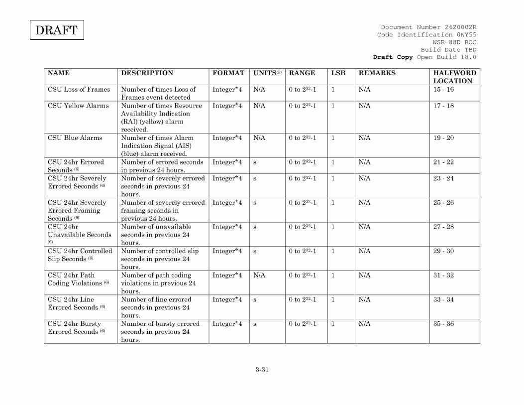
Document Number 2620002R Code Identification 0WY55
WSR-88D ROC Build Date TBD
Draft Copy Open Build 18.0
3-31
DRAFT
NAME DESCRIPTION FORMAT UNITS(5) RANGE LSB REMARKS HALFWORD LOCATION
CSU Loss of Frames Number of times Loss of Frames event detected
Integer*4 N/A 0 to 232-1 1 N/A 15 - 16
CSU Yellow Alarms Number of times Resource Availability Indication (RAI) (yellow) alarm received.
Integer*4 N/A 0 to 232-1 1 N/A 17 - 18
CSU Blue Alarms Number of times Alarm Indication Signal (AIS) (blue) alarm received.
Integer*4 N/A 0 to 232-1 1 N/A 19 - 20
CSU 24hr Errored Seconds (6)
Number of errored seconds in previous 24 hours.
Integer*4 s 0 to 232-1 1 N/A 21 - 22
CSU 24hr Severely Errored Seconds (6)
Number of severely errored seconds in previous 24 hours.
Integer*4 s 0 to 232-1 1 N/A 23 - 24
CSU 24hr Severely Errored Framing Seconds (6)
Number of severely errored framing seconds in previous 24 hours.
Integer*4 s 0 to 232-1 1 N/A 25 - 26
CSU 24hr Unavailable Seconds (6)
Number of unavailable seconds in previous 24 hours.
Integer*4 s 0 to 232-1 1 N/A 27 - 28
CSU 24hr Controlled Slip Seconds (6)
Number of controlled slip seconds in previous 24 hours.
Integer*4 s 0 to 232-1 1 N/A 29 - 30
CSU 24hr Path Coding Violations (6)
Number of path coding violations in previous 24 hours.
Integer*4 N/A 0 to 232-1 1 N/A 31 - 32
CSU 24hr Line Errored Seconds (6)
Number of line errored seconds in previous 24 hours.
Integer*4 s 0 to 232-1 1 N/A 33 - 34
CSU 24hr Bursty Errored Seconds (6)
Number of bursty errored seconds in previous 24 hours.
Integer*4 s 0 to 232-1 1 N/A 35 - 36

Document Number 2620002R Code Identification 0WY55
WSR-88D ROC Build Date TBD
Draft Copy Open Build 18.0
3-32
DRAFT
NAME DESCRIPTION FORMAT UNITS(5) RANGE LSB REMARKS HALFWORD LOCATION
CSU 24hr Degraded Minutes (6)
Number of degraded minutes in previous 24 hours.
Integer*4 min 0 to 232-1 1 N/A 37 - 38
SPARE N/A N/A N/A N/A N/A N/A 39 - 40 LAN Switch CPU Utilization
Integer*4 %
0 to 100 1 N/A 41 - 42
LAN Switch Memory Utilization
Integer*2 % 0 to 100 1 N/A 43
Spare N/A N/A N/A N/A N/A See Note (3) 44 Spare N/A N/A N/A N/A N/A N/A 45 - 46 Spare N/A N/A N/A N/A N/A N/A 47 - 48 GPS Satellites Current number of GPS
satellites used in position and time fix calculation
SInteger*4 N/A -(231) to +(231-1)
1 N/A 49 - 50
Spare N/A N/A N/A N/A N/A N/A 51 - 52 IPC Status Status of the
communications between channels on a redundant system. N/A on a Single channel system.
Integer*2 N/A 0 to 2 1 0=OK, 1=Fail, 2=N/A
53
Commanded Channel Control
Indicates which channel the RDA has commanded to be the controlling channel. This is not necessarily the channel which is in control.
Integer*2 N/A 0 to 2 1 0=N/A, 1=Channel 1, 2=Channel 2
54
SPARE N/A N/A N/A N/A N/A N/A 55-57 AME Polarization Integer*2 N/A 0 to 2 1 0 = H Only
1 = H + V 2 = V Only
58
AME Internal Temperature
Real*4 deg C -40.0 to +125.0
0.1 N/A 59-60
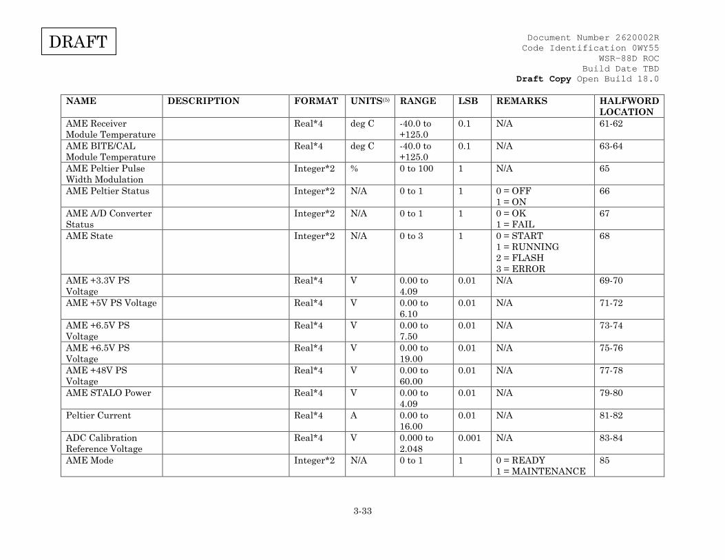
Document Number 2620002R Code Identification 0WY55
WSR-88D ROC Build Date TBD
Draft Copy Open Build 18.0
3-33
DRAFT
NAME DESCRIPTION FORMAT UNITS(5) RANGE LSB REMARKS HALFWORD LOCATION
AME Receiver Module Temperature
Real*4 deg C -40.0 to +125.0
0.1 N/A 61-62
AME BITE/CAL Module Temperature
Real*4 deg C -40.0 to +125.0
0.1 N/A 63-64
AME Peltier Pulse Width Modulation
Integer*2 % 0 to 100 1 N/A 65
AME Peltier Status Integer*2 N/A 0 to 1 1 0 = OFF 1 = ON
66
AME A/D Converter Status
Integer*2 N/A 0 to 1 1 0 = OK 1 = FAIL
67
AME State Integer*2 N/A 0 to 3 1 0 = START 1 = RUNNING 2 = FLASH 3 = ERROR
68
AME +3.3V PS Voltage
Real*4 V 0.00 to 4.09
0.01 N/A 69-70
AME +5V PS Voltage Real*4 V 0.00 to 6.10
0.01 N/A 71-72
AME +6.5V PS Voltage
Real*4 V 0.00 to 7.50
0.01 N/A 73-74
AME +6.5V PS Voltage
Real*4 V 0.00 to 19.00
0.01 N/A 75-76
AME +48V PS Voltage
Real*4 V 0.00 to 60.00
0.01 N/A 77-78
AME STALO Power Real*4 V 0.00 to 4.09
0.01 N/A 79-80
Peltier Current Real*4 A 0.00 to 16.00
0.01 N/A 81-82
ADC Calibration Reference Voltage
Real*4 V 0.000 to 2.048
0.001 N/A 83-84
AME Mode Integer*2 N/A 0 to 1 1 0 = READY 1 = MAINTENANCE
85
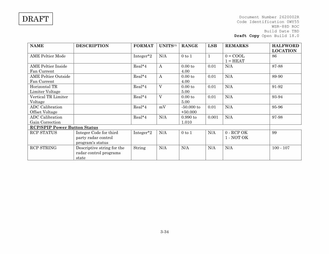
Document Number 2620002R Code Identification 0WY55
WSR-88D ROC Build Date TBD
Draft Copy Open Build 18.0
3-34
DRAFT
NAME DESCRIPTION FORMAT UNITS(5) RANGE LSB REMARKS HALFWORD LOCATION
AME Peltier Mode Integer*2 N/A 0 to 1 1 0 = COOL 1 = HEAT
86
AME Peltier Inside Fan Current
Real*4 A 0.00 to 4.00
0.01 N/A 87-88
AME Peltier Outside Fan Current
Real*4 A 0.00 to 4.00
0.01 N/A 89-90
Horizontal TR Limiter Voltage
Real*4 V 0.00 to 5.00
0.01 N/A 91-92
Vertical TR Limiter Voltage
Real*4 V 0.00 to 5.00
0.01 N/A 93-94
ADC Calibration Offset Voltage
Real*4 mV -50.000 to +50.000
0.01 N/A 95-96
ADC Calibration Gain Correction
Real*4 N/A 0.990 to 1.010
0.001 N/A 97-98
RCP/SPIP Power Button Status RCP STATUS Integer Code for third
party radar control program's status
Integer*2 N/A 0 to 1 N/A 0 - RCP OK 1 - NOT OK
99
RCP STRING Descriptive string for the radar control programs state
String N/A N/A N/A N/A 100 - 107
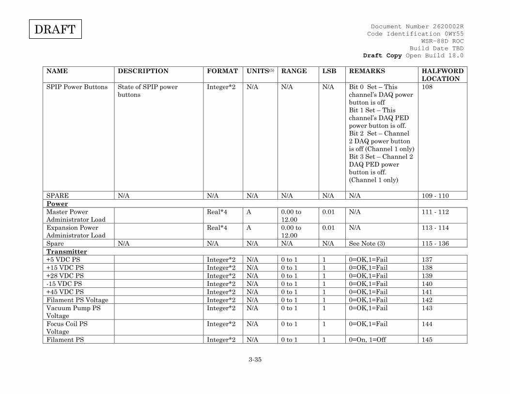
Document Number 2620002R Code Identification 0WY55
WSR-88D ROC Build Date TBD
Draft Copy Open Build 18.0
3-35
DRAFT
NAME DESCRIPTION FORMAT UNITS(5) RANGE LSB REMARKS HALFWORD LOCATION
SPIP Power Buttons State of SPIP power buttons
Integer*2 N/A N/A N/A Bit 0 Set – This channel’s DAQ power button is off Bit 1 Set – This channel’s DAQ PED power button is off. Bit 2 Set – Channel 2 DAQ power button is off (Channel 1 only) Bit 3 Set – Channel 2 DAQ PED power button is off. (Channel 1 only)
108
SPARE N/A N/A N/A N/A N/A N/A 109 - 110 Power Master Power Administrator Load
Real*4 A 0.00 to 12.00
0.01 N/A 111 - 112
Expansion Power Administrator Load
Real*4 A 0.00 to 12.00
0.01 N/A 113 - 114
Spare N/A N/A N/A N/A N/A See Note (3) 115 - 136 Transmitter +5 VDC PS Integer*2 N/A 0 to 1 1 0=OK,1=Fail 137 +15 VDC PS Integer*2 N/A 0 to 1 1 0=OK,1=Fail 138 +28 VDC PS Integer*2 N/A 0 to 1 1 0=OK,1=Fail 139 -15 VDC PS Integer*2 N/A 0 to 1 1 0=OK,1=Fail 140 +45 VDC PS Integer*2 N/A 0 to 1 1 0=OK,1=Fail 141 Filament PS Voltage Integer*2 N/A 0 to 1 1 0=OK,1=Fail 142 Vacuum Pump PS Voltage
Integer*2 N/A 0 to 1 1 0=OK,1=Fail 143
Focus Coil PS Voltage
Integer*2 N/A 0 to 1 1 0=OK,1=Fail 144
Filament PS Integer*2 N/A 0 to 1 1 0=On, 1=Off 145
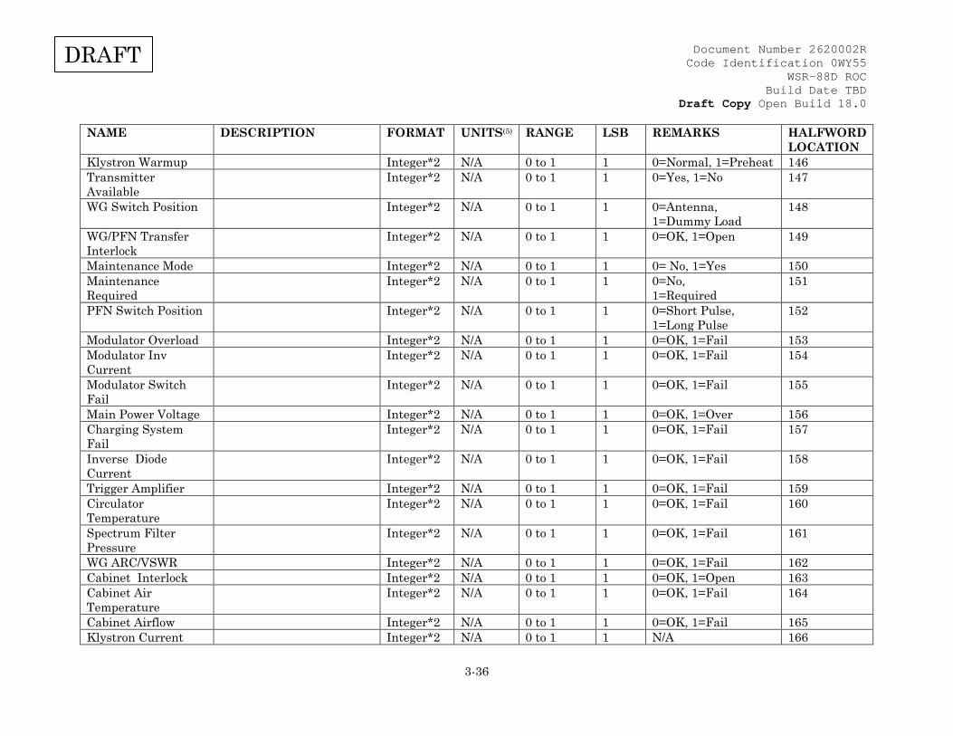
Document Number 2620002R Code Identification 0WY55
WSR-88D ROC Build Date TBD
Draft Copy Open Build 18.0
3-36
DRAFT
NAME DESCRIPTION FORMAT UNITS(5) RANGE LSB REMARKS HALFWORD LOCATION
Klystron Warmup Integer*2 N/A 0 to 1 1 0=Normal, 1=Preheat 146 Transmitter Available
Integer*2 N/A 0 to 1 1 0=Yes, 1=No 147
WG Switch Position Integer*2 N/A 0 to 1 1 0=Antenna, 1=Dummy Load
148
WG/PFN Transfer Interlock
Integer*2 N/A 0 to 1 1 0=OK, 1=Open 149
Maintenance Mode Integer*2 N/A 0 to 1 1 0= No, 1=Yes 150 Maintenance Required
Integer*2 N/A 0 to 1 1 0=No, 1=Required
151
PFN Switch Position Integer*2 N/A 0 to 1 1 0=Short Pulse, 1=Long Pulse
152
Modulator Overload Integer*2 N/A 0 to 1 1 0=OK, 1=Fail 153 Modulator Inv Current
Integer*2 N/A 0 to 1 1 0=OK, 1=Fail 154
Modulator Switch Fail
Integer*2 N/A 0 to 1 1 0=OK, 1=Fail 155
Main Power Voltage Integer*2 N/A 0 to 1 1 0=OK, 1=Over 156 Charging System Fail
Integer*2 N/A 0 to 1 1 0=OK, 1=Fail 157
Inverse Diode Current
Integer*2 N/A 0 to 1 1 0=OK, 1=Fail 158
Trigger Amplifier Integer*2 N/A 0 to 1 1 0=OK, 1=Fail 159 Circulator Temperature
Integer*2 N/A 0 to 1 1 0=OK, 1=Fail 160
Spectrum Filter Pressure
Integer*2 N/A 0 to 1 1 0=OK, 1=Fail 161
WG ARC/VSWR Integer*2 N/A 0 to 1 1 0=OK, 1=Fail 162 Cabinet Interlock Integer*2 N/A 0 to 1 1 0=OK, 1=Open 163 Cabinet Air Temperature
Integer*2 N/A 0 to 1 1 0=OK, 1=Fail 164
Cabinet Airflow Integer*2 N/A 0 to 1 1 0=OK, 1=Fail 165 Klystron Current Integer*2 N/A 0 to 1 1 N/A 166
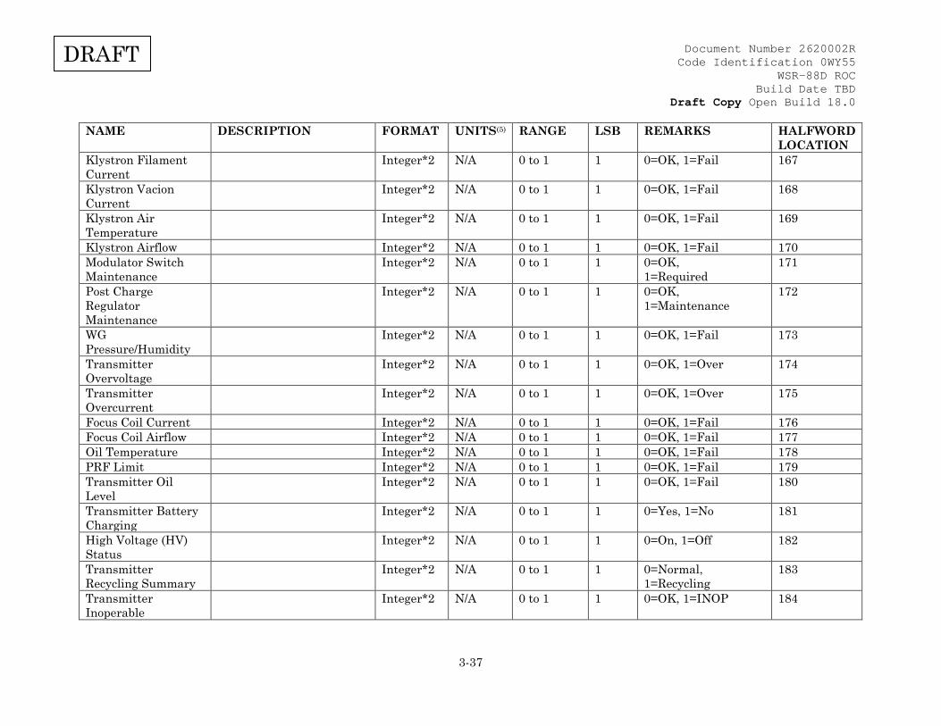
Document Number 2620002R Code Identification 0WY55
WSR-88D ROC Build Date TBD
Draft Copy Open Build 18.0
3-37
DRAFT
NAME DESCRIPTION FORMAT UNITS(5) RANGE LSB REMARKS HALFWORD LOCATION
Klystron Filament Current
Integer*2 N/A 0 to 1 1 0=OK, 1=Fail 167
Klystron Vacion Current
Integer*2 N/A 0 to 1 1 0=OK, 1=Fail 168
Klystron Air Temperature
Integer*2 N/A 0 to 1 1 0=OK, 1=Fail 169
Klystron Airflow Integer*2 N/A 0 to 1 1 0=OK, 1=Fail 170 Modulator Switch Maintenance
Integer*2 N/A 0 to 1 1 0=OK, 1=Required
171
Post Charge Regulator Maintenance
Integer*2 N/A 0 to 1 1 0=OK, 1=Maintenance
172
WG Pressure/Humidity
Integer*2 N/A 0 to 1 1 0=OK, 1=Fail 173
Transmitter Overvoltage
Integer*2 N/A 0 to 1 1 0=OK, 1=Over 174
Transmitter Overcurrent
Integer*2 N/A 0 to 1 1 0=OK, 1=Over 175
Focus Coil Current Integer*2 N/A 0 to 1 1 0=OK, 1=Fail 176 Focus Coil Airflow Integer*2 N/A 0 to 1 1 0=OK, 1=Fail 177 Oil Temperature Integer*2 N/A 0 to 1 1 0=OK, 1=Fail 178 PRF Limit Integer*2 N/A 0 to 1 1 0=OK, 1=Fail 179 Transmitter Oil Level
Integer*2 N/A 0 to 1 1 0=OK, 1=Fail 180
Transmitter Battery Charging
Integer*2 N/A 0 to 1 1 0=Yes, 1=No 181
High Voltage (HV) Status
Integer*2 N/A 0 to 1 1 0=On, 1=Off 182
Transmitter Recycling Summary
Integer*2 N/A 0 to 1 1 0=Normal, 1=Recycling
183
Transmitter Inoperable
Integer*2 N/A 0 to 1 1 0=OK, 1=INOP 184
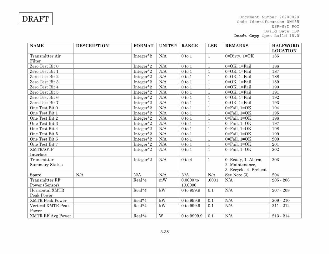
Document Number 2620002R Code Identification 0WY55
WSR-88D ROC Build Date TBD
Draft Copy Open Build 18.0
3-38
DRAFT
NAME DESCRIPTION FORMAT UNITS(5) RANGE LSB REMARKS HALFWORD LOCATION
Transmitter Air Filter
Integer*2 N/A 0 to 1 1 0=Dirty, 1=OK 185
Zero Test Bit 0 Integer*2 N/A 0 to 1 1 0=OK, 1=Fail 186 Zero Test Bit 1 Integer*2 N/A 0 to 1 1 0=OK, 1=Fail 187 Zero Test Bit 2 Integer*2 N/A 0 to 1 1 0=OK, 1=Fail 188 Zero Test Bit 3 Integer*2 N/A 0 to 1 1 0=OK, 1=Fail 189 Zero Test Bit 4 Integer*2 N/A 0 to 1 1 0=OK, 1=Fail 190 Zero Test Bit 5 Integer*2 N/A 0 to 1 1 0=OK, 1=Fail 191 Zero Test Bit 6 Integer*2 N/A 0 to 1 1 0=OK, 1=Fail 192 Zero Test Bit 7 Integer*2 N/A 0 to 1 1 0=OK, 1=Fail 193 One Test Bit 0 Integer*2 N/A 0 to 1 1 0=Fail, 1=OK 194 One Test Bit 1 Integer*2 N/A 0 to 1 1 0=Fail, 1=OK 195 One Test Bit 2 Integer*2 N/A 0 to 1 1 0=Fail, 1=OK 196 One Test Bit 3 Integer*2 N/A 0 to 1 1 0=Fail, 1=OK 197 One Test Bit 4 Integer*2 N/A 0 to 1 1 0=Fail, 1=OK 198 One Test Bit 5 Integer*2 N/A 0 to 1 1 0=Fail, 1=OK 199 One Test Bit 6 Integer*2 N/A 0 to 1 1 0=Fail, 1=OK 200 One Test Bit 7 Integer*2 N/A 0 to 1 1 0=Fail, 1=OK 201 XMTR/SPIP Interface
Integer*2 N/A 0 to 1 1 0=Fail, 1=OK 202
Transmitter Summary Status
Integer*2 N/A 0 to 4 1 0=Ready, 1=Alarm, 2=Maintenance, 3=Recycle, 4=Preheat
203
Spare N/A N/A N/A N/A N/A See Note (3) 204 Transmitter RF Power (Sensor)
Real*4 mW 0.0000 to 10.0000
.0001 N/A
205 - 206
Horizontal XMTR Peak Power
Real*4 kW 0 to 999.9 0.1 N/A 207 - 208
XMTR Peak Power Real*4 kW 0 to 999.9 0.1 N/A 209 - 210 Vertical XMTR Peak Power
Real*4 kW 0 to 999.9 0.1 N/A 211 - 212
XMTR RF Avg Power Real*4 W 0 to 9999.9 0.1 N/A 213 - 214
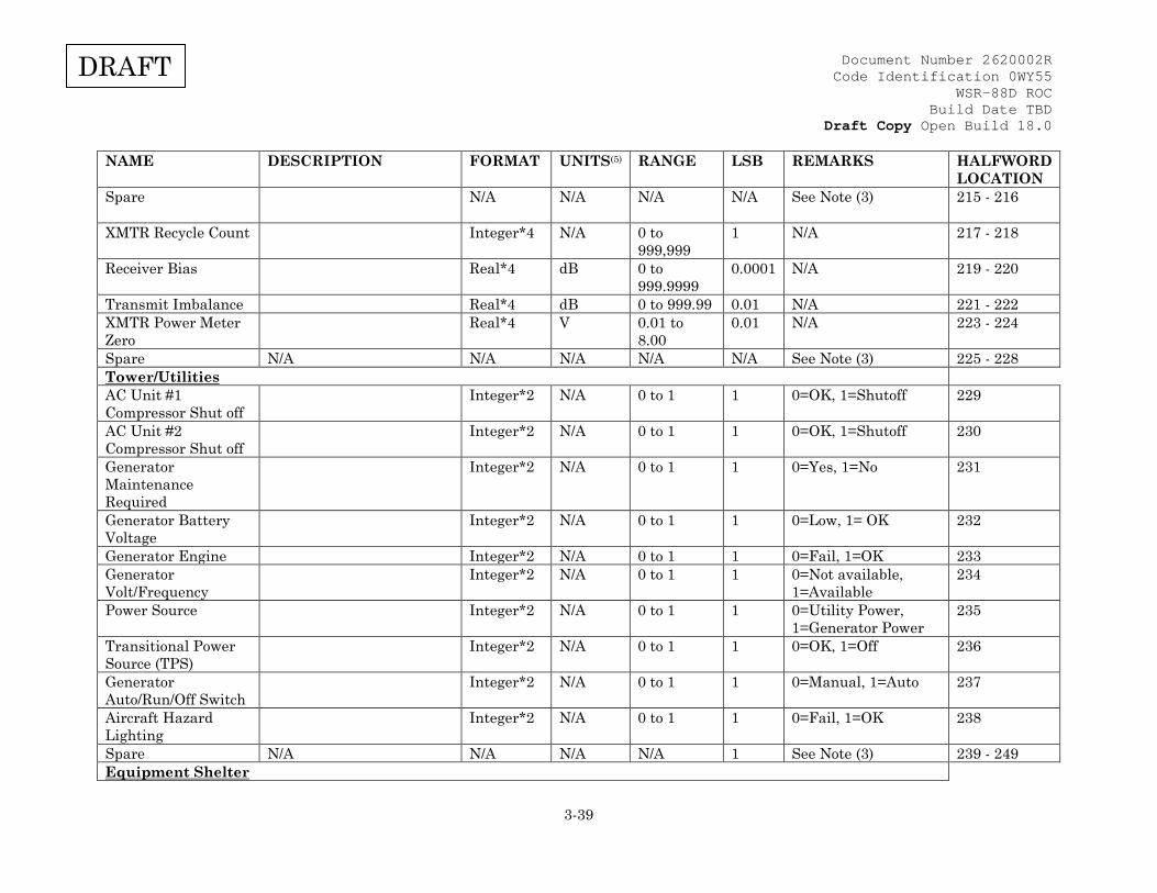
Document Number 2620002R Code Identification 0WY55
WSR-88D ROC Build Date TBD
Draft Copy Open Build 18.0
3-39
DRAFT
NAME DESCRIPTION FORMAT UNITS(5) RANGE LSB REMARKS HALFWORD LOCATION
Spare N/A N/A N/A N/A See Note (3)
215 - 216
XMTR Recycle Count Integer*4 N/A 0 to 999,999
1 N/A 217 - 218
Receiver Bias Real*4 dB 0 to 999.9999
0.0001 N/A 219 - 220
Transmit Imbalance Real*4 dB 0 to 999.99 0.01 N/A 221 - 222 XMTR Power Meter Zero
Real*4 V 0.01 to 8.00
0.01 N/A 223 - 224
Spare N/A N/A N/A N/A N/A See Note (3) 225 - 228 Tower/Utilities AC Unit #1 Compressor Shut off
Integer*2 N/A 0 to 1 1 0=OK, 1=Shutoff 229
AC Unit #2 Compressor Shut off
Integer*2 N/A 0 to 1 1 0=OK, 1=Shutoff 230
Generator Maintenance Required
Integer*2 N/A 0 to 1 1 0=Yes, 1=No 231
Generator Battery Voltage
Integer*2 N/A 0 to 1 1 0=Low, 1= OK 232
Generator Engine Integer*2 N/A 0 to 1 1 0=Fail, 1=OK 233 Generator Volt/Frequency
Integer*2 N/A 0 to 1 1 0=Not available, 1=Available
234
Power Source Integer*2 N/A 0 to 1 1 0=Utility Power, 1=Generator Power
235
Transitional Power Source (TPS)
Integer*2 N/A 0 to 1 1 0=OK, 1=Off 236
Generator Auto/Run/Off Switch
Integer*2 N/A 0 to 1 1 0=Manual, 1=Auto 237
Aircraft Hazard Lighting
Integer*2 N/A 0 to 1 1 0=Fail, 1=OK 238
Spare N/A N/A N/A N/A 1 See Note (3) 239 - 249 Equipment Shelter
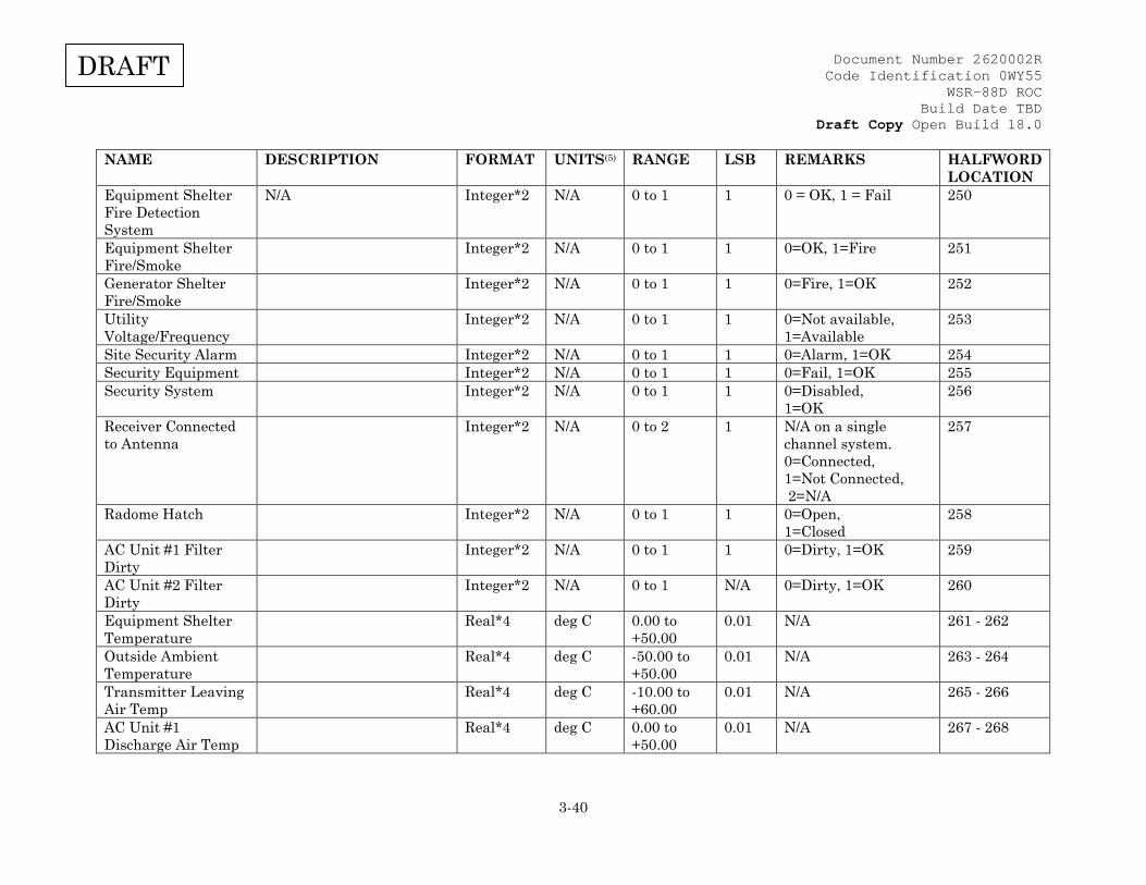
Document Number 2620002R Code Identification 0WY55
WSR-88D ROC Build Date TBD
Draft Copy Open Build 18.0
3-40
DRAFT
NAME DESCRIPTION FORMAT UNITS(5) RANGE LSB REMARKS HALFWORD LOCATION
Equipment Shelter Fire Detection System
N/A Integer*2 N/A 0 to 1 1 0 = OK, 1 = Fail 250
Equipment Shelter Fire/Smoke
Integer*2 N/A 0 to 1 1 0=OK, 1=Fire 251
Generator Shelter Fire/Smoke
Integer*2 N/A 0 to 1 1 0=Fire, 1=OK 252
Utility Voltage/Frequency
Integer*2 N/A 0 to 1 1 0=Not available, 1=Available
253
Site Security Alarm Integer*2 N/A 0 to 1 1 0=Alarm, 1=OK 254 Security Equipment Integer*2 N/A 0 to 1 1 0=Fail, 1=OK 255 Security System Integer*2 N/A 0 to 1 1 0=Disabled,
1=OK 256
Receiver Connected to Antenna
Integer*2 N/A 0 to 2 1 N/A on a single channel system. 0=Connected, 1=Not Connected, 2=N/A
257
Radome Hatch Integer*2 N/A 0 to 1 1 0=Open, 1=Closed
258
AC Unit #1 Filter Dirty
Integer*2 N/A 0 to 1 1 0=Dirty, 1=OK 259
AC Unit #2 Filter Dirty
Integer*2 N/A 0 to 1 N/A 0=Dirty, 1=OK 260
Equipment Shelter Temperature
Real*4 deg C 0.00 to +50.00
0.01 N/A 261 - 262
Outside Ambient Temperature
Real*4 deg C -50.00 to +50.00
0.01 N/A 263 - 264
Transmitter Leaving Air Temp
Real*4 deg C -10.00 to +60.00
0.01 N/A 265 - 266
AC Unit #1 Discharge Air Temp
Real*4 deg C 0.00 to +50.00
0.01 N/A 267 - 268
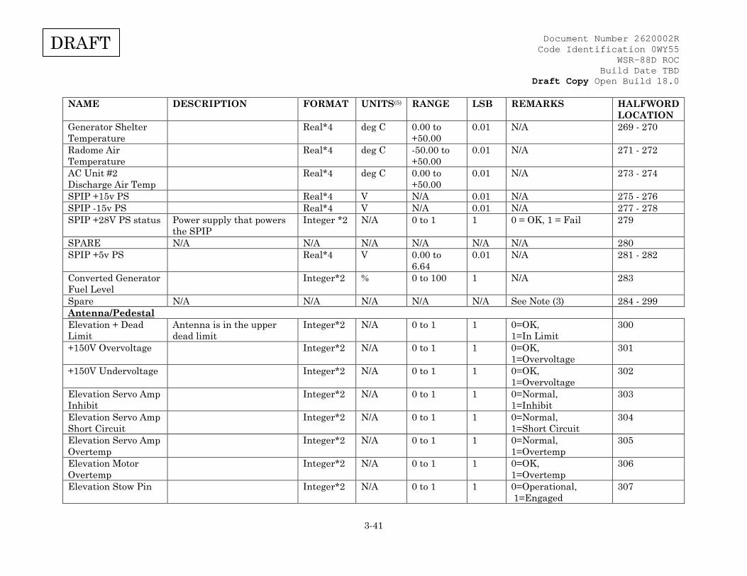
Document Number 2620002R Code Identification 0WY55
WSR-88D ROC Build Date TBD
Draft Copy Open Build 18.0
3-41
DRAFT
NAME DESCRIPTION FORMAT UNITS(5) RANGE LSB REMARKS HALFWORD LOCATION
Generator Shelter Temperature
Real*4 deg C 0.00 to +50.00
0.01 N/A 269 - 270
Radome Air Temperature
Real*4 deg C -50.00 to +50.00
0.01 N/A 271 - 272
AC Unit #2 Discharge Air Temp
Real*4 deg C 0.00 to +50.00
0.01 N/A 273 - 274
SPIP +15v PS Real*4 V N/A 0.01 N/A 275 - 276 SPIP -15v PS Real*4 V N/A 0.01 N/A 277 - 278 SPIP +28V PS status Power supply that powers
the SPIP Integer *2 N/A 0 to 1 1 0 = OK, 1 = Fail 279
SPARE N/A N/A N/A N/A N/A N/A 280 SPIP +5v PS Real*4 V 0.00 to
6.64 0.01 N/A 281 - 282
Converted Generator Fuel Level
Integer*2 % 0 to 100 1 N/A 283
Spare N/A N/A N/A N/A N/A See Note (3) 284 - 299 Antenna/Pedestal Elevation + Dead Limit
Antenna is in the upper dead limit
Integer*2 N/A 0 to 1 1 0=OK, 1=In Limit
300
+150V Overvoltage Integer*2 N/A 0 to 1 1 0=OK, 1=Overvoltage
301
+150V Undervoltage Integer*2 N/A 0 to 1 1 0=OK, 1=Overvoltage
302
Elevation Servo Amp Inhibit
Integer*2 N/A 0 to 1 1 0=Normal, 1=Inhibit
303
Elevation Servo Amp Short Circuit
Integer*2 N/A 0 to 1 1 0=Normal, 1=Short Circuit
304
Elevation Servo Amp Overtemp
Integer*2 N/A 0 to 1 1 0=Normal, 1=Overtemp
305
Elevation Motor Overtemp
Integer*2 N/A 0 to 1 1 0=OK, 1=Overtemp
306
Elevation Stow Pin Integer*2 N/A 0 to 1 1 0=Operational, 1=Engaged
307
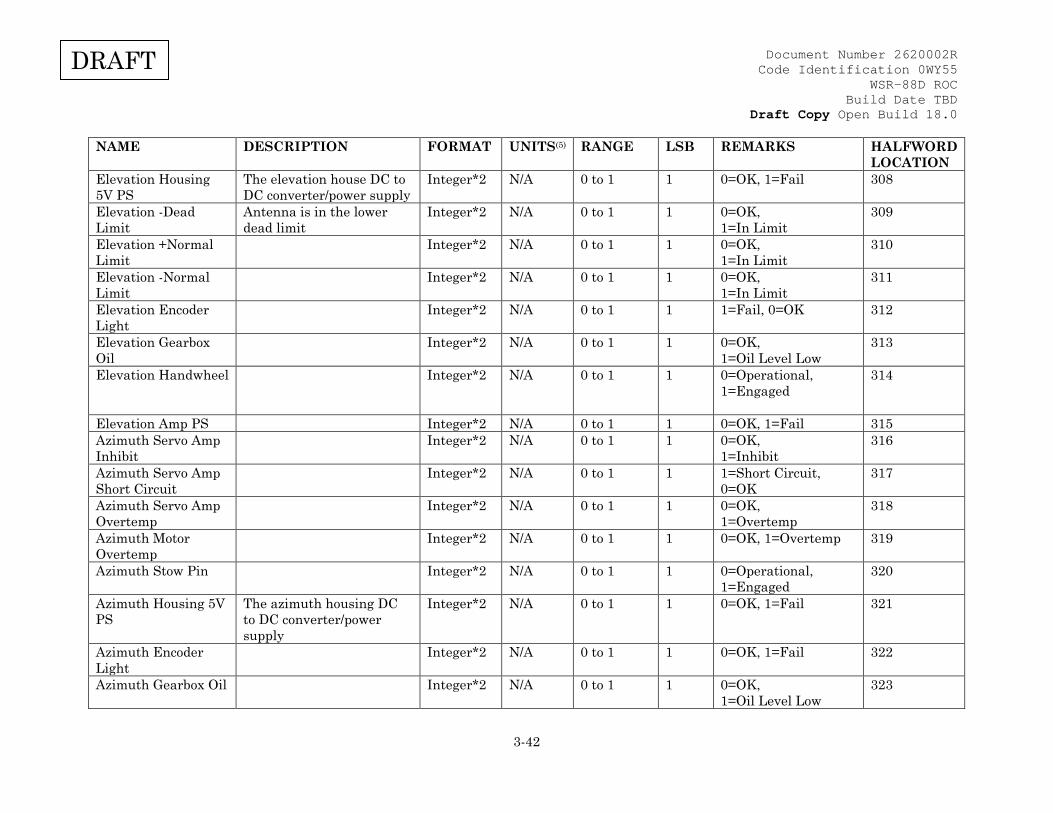
Document Number 2620002R Code Identification 0WY55
WSR-88D ROC Build Date TBD
Draft Copy Open Build 18.0
3-42
DRAFT
NAME DESCRIPTION FORMAT UNITS(5) RANGE LSB REMARKS HALFWORD LOCATION
Elevation Housing 5V PS
The elevation house DC to DC converter/power supply
Integer*2 N/A 0 to 1 1 0=OK, 1=Fail 308
Elevation -Dead Limit
Antenna is in the lower dead limit
Integer*2 N/A 0 to 1 1 0=OK, 1=In Limit
309
Elevation +Normal Limit
Integer*2 N/A 0 to 1 1 0=OK, 1=In Limit
310
Elevation -Normal Limit
Integer*2 N/A 0 to 1 1 0=OK, 1=In Limit
311
Elevation Encoder Light
Integer*2 N/A 0 to 1 1 1=Fail, 0=OK 312
Elevation Gearbox Oil
Integer*2 N/A 0 to 1 1 0=OK, 1=Oil Level Low
313
Elevation Handwheel Integer*2 N/A 0 to 1 1 0=Operational, 1=Engaged
314
Elevation Amp PS Integer*2 N/A 0 to 1 1 0=OK, 1=Fail 315 Azimuth Servo Amp Inhibit
Integer*2 N/A 0 to 1 1 0=OK, 1=Inhibit
316
Azimuth Servo Amp Short Circuit
Integer*2 N/A 0 to 1 1 1=Short Circuit, 0=OK
317
Azimuth Servo Amp Overtemp
Integer*2 N/A 0 to 1 1 0=OK, 1=Overtemp
318
Azimuth Motor Overtemp
Integer*2 N/A 0 to 1 1 0=OK, 1=Overtemp 319
Azimuth Stow Pin Integer*2 N/A 0 to 1 1 0=Operational, 1=Engaged
320
Azimuth Housing 5V PS
The azimuth housing DC to DC converter/power supply
Integer*2 N/A 0 to 1 1 0=OK, 1=Fail 321
Azimuth Encoder Light
Integer*2 N/A 0 to 1 1 0=OK, 1=Fail 322
Azimuth Gearbox Oil Integer*2 N/A 0 to 1 1 0=OK, 1=Oil Level Low
323

Document Number 2620002R Code Identification 0WY55
WSR-88D ROC Build Date TBD
Draft Copy Open Build 18.0
3-43
DRAFT
NAME DESCRIPTION FORMAT UNITS(5) RANGE LSB REMARKS HALFWORD LOCATION
Azimuth Bull Gear Oil
Integer*2 N/A 0 to 1 1 0=OK, 1=Oil Level Low
324
Azimuth Handwheel Integer*2 N/A 0 to 1 1 0=Operational, 1=Engaged
325
Azimuth Servo Amp PS
Integer*2 N/A 0 to 1 1 0=OK, 1=Fail 326
Servo Integer*2 N/A 0 to 1 1 0=On, 1=Off 327 Pedestal Interlock Switch
Integer*2 N/A 0 to 1 1 0=Operational, 1=Safe
328
Spare N/A N/A N/A N/A N/A See Note (3). 329 - 340 RF Generator/Receiver COHO/Clock Integer*2 N/A 0 to 1 1 0=OK, 1=Fail 341 Rf Generator Frequency Select Oscillator
Integer*2 N/A 0 to 1 1 0=OK, 1=Fail 342
Rf Generator RF/STALO
Integer*2 N/A 0 to 1 1 0=OK, 1=Fail 343
Rf Generator Phase Shifted COHO
Integer*2 N/A 0 to 1 1 0=OK, 1=Fail 344
+9v Receiver PS Integer*2 N/A 0 to 1 1 0=OK, 1=Fail 345 +5v Receiver PS Integer*2 N/A 0 to 1 1 0=OK, 1=Fail 346 ±18v Receiver PS Integer*2 N/A 0 to 1 1 0=OK, 1=Fail 347 -9v Receiver PS Integer*2 N/A 0 to 1 1 0=OK, 1=Fail 348 +5v Single Channel RDAIU PS
Integer*2 N/A 0 to 1 1 0=OK, 1=Fail 349
Spare N/A N/A N/A N/A N/A See Note (3) 350 Horizontal Short Pulse Noise
Real*4 dBm -100.00 to -50.00
0.01 N/A 351 - 352
Horizontal Long Pulse Noise
Real*4 dBm -100.00 to -50.00
0.01 N/A 353 - 354
Horizontal Noise Temperature
Real*4 K 0 to 9999.99
0.01 N/A 355 - 356

Document Number 2620002R Code Identification 0WY55
WSR-88D ROC Build Date TBD
Draft Copy Open Build 18.0
3-44
DRAFT
NAME DESCRIPTION FORMAT UNITS(5) RANGE LSB REMARKS HALFWORD LOCATION
Vertical Noise Short Pulse
N/A N/A N/A N/A N/A See Note (3) 357 - 358
Vertical Noise Long Pulse
Real*4 dBm -100.00 to -50.00
0.01 N/A 359-360
Vertical Noise Temperature
Real*4 K 0 to 9999.99
0.01 N/A 361-362
Calibration Horizontal Linearity Real*4 N/A 0.5000 to
1.5000 0.0001 N/A 363 - 364
Horizontal Dynamic Range
Real*4 dB 0.000 to 120.000
0.001 N/A 365 - 366
Horizontal Delta dBZ0
Real*4 dB -198.00 to +198.00
0.01 N/A 367 - 368
Vertical Delta dBZ0 Real*4 dB -198.00 to +198.00
0.01 N/A 369 - 370
KD Peak Measured Real*4 dBm -99.90 to +99.90
0.01 N/A 371 - 372
Spare N/A N/A N/A N/A N/A See Note (3) 373 - 374 Short Pulse, Horizontal dBZ0
Real*4 dBZ -99.900 to +99.900
0.0001 N/A 375 - 376
Long Pulse, Horizontal dBZ0
Real*4 dBZ -99.9000 to +99.9000
0.0001 N/A 377 - 378
Velocity (Processed) Integer*2 N/A 0 to 1 1 0=Good, 1=Fail 379 Width (Processed) Integer*2 N/A 0 to 1 1 0=Good, 1=Fail 380 Velocity (RF Gen) Integer*2 N/A 0 to 1 1 0=Good, 1=Fail 381 Width (RF Gen) Integer*2 N/A 0 to 1 1 0=Good, 1=Fail 382 Horizontal I0 Real*4 dBm -999.9000
to +999.9000
0.0001 N/A 383 - 384
Vertical I0 Real*4 dBm -999.9000 to +999.9000
0.0001 N/A 385 - 386

Document Number 2620002R Code Identification 0WY55
WSR-88D ROC Build Date TBD
Draft Copy Open Build 18.0
3-45
DRAFT
NAME DESCRIPTION FORMAT UNITS(5) RANGE LSB REMARKS HALFWORD LOCATION
Vertical Dynamic Range
Real*4 dB 0.000 to 120.000
0.001 N/A 387 - 388
Short Pulse, Vertical dBZ0
Real*4 dBZ -99.9000 to +99.9000
0.0001 N/A 389 - 390
Long Pulse, Vertical dBZ0
Real*4 dBZ -99.9000 to +99.9000
0.0001 N/A 391 - 392
Spare N/A N/A N/A N/A N/A See Note (3) 393 - 394 Spare N/A N/A N/A N/A N/A See Note (3) 395 - 396 Horizontal Power Sense
Real*4 dBm -999.9000 to +999.9000
0.0001 N/A 397 - 398
Vertical Power Sense Real*4 dBm -999.9000 to +999.9000
0.0001 N/A 399 - 400
ZDR Bias Real*4 dB -999.9000 to +999.9000
0.0001 N/A 401 - 402
Spare N/A N/A N/A N/A N/A See Note (3) 403 - 408 Clutter Suppression Delta
Real*4 dB -99.90 to +99.90
0.01 N/A 409-410
Clutter Suppression Unfiltered Power
Real*4 dBZ -99.90 to +99.90
0.01 N/A 411 - 412
Clutter Suppression Filtered Power
Real*4 dBZ -99.90 to +99.90
0.01 N/A 413 - 414
Spare N/A N/A N/A N/A N/A 415 - 416 Spare N/A N/A N/A N/A N/A 417 - 418 Spare N/A N/A N/A N/A N/A See Note (3) 419 - 422 Spare N/A N/A N/A N/A N/A See Note (3) 423 - 424 Vertical Linearity Real*4 N/A 0.5000 to
1.5000 0.0001 N/A 425 - 426
Spare N/A N/A N/A N/A N/A See Note (3) 427 - 430
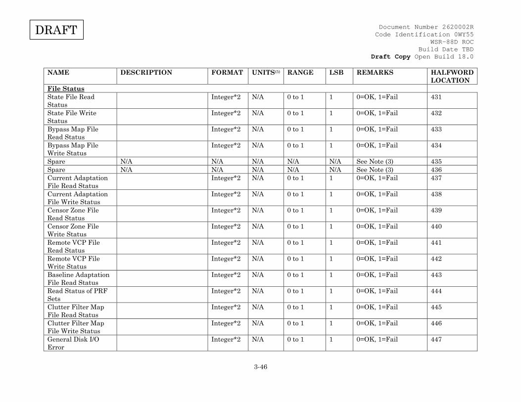
Document Number 2620002R Code Identification 0WY55
WSR-88D ROC Build Date TBD
Draft Copy Open Build 18.0
3-46
DRAFT
NAME DESCRIPTION FORMAT UNITS(5) RANGE LSB REMARKS HALFWORD LOCATION
File Status State File Read Status
Integer*2 N/A 0 to 1 1 0=OK, 1=Fail 431
State File Write Status
Integer*2 N/A 0 to 1 1 0=OK, 1=Fail 432
Bypass Map File Read Status
Integer*2 N/A 0 to 1 1 0=OK, 1=Fail 433
Bypass Map File Write Status
Integer*2 N/A 0 to 1 1 0=OK, 1=Fail 434
Spare N/A N/A N/A N/A N/A See Note (3) 435 Spare N/A N/A N/A N/A N/A See Note (3) 436 Current Adaptation File Read Status
Integer*2 N/A 0 to 1 1 0=OK, 1=Fail 437
Current Adaptation File Write Status
Integer*2 N/A 0 to 1 1 0=OK, 1=Fail 438
Censor Zone File Read Status
Integer*2 N/A 0 to 1 1 0=OK, 1=Fail 439
Censor Zone File Write Status
Integer*2 N/A 0 to 1 1 0=OK, 1=Fail 440
Remote VCP File Read Status
Integer*2 N/A 0 to 1 1 0=OK, 1=Fail 441
Remote VCP File Write Status
Integer*2 N/A 0 to 1 1 0=OK, 1=Fail 442
Baseline Adaptation File Read Status
Integer*2 N/A 0 to 1 1 0=OK, 1=Fail 443
Read Status of PRF Sets
Integer*2 N/A 0 to 1 1 0=OK, 1=Fail 444
Clutter Filter Map File Read Status
Integer*2 N/A 0 to 1 1 0=OK, 1=Fail 445
Clutter Filter Map File Write Status
Integer*2 N/A 0 to 1 1 0=OK, 1=Fail 446
General Disk I/O Error
Integer*2 N/A 0 to 1 1 0=OK, 1=Fail 447
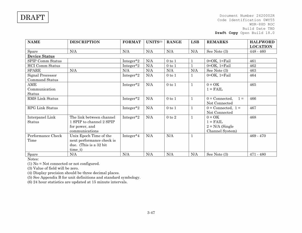
Document Number 2620002R Code Identification 0WY55
WSR-88D ROC Build Date TBD
Draft Copy Open Build 18.0
3-47
DRAFT
NAME DESCRIPTION FORMAT UNITS(5) RANGE LSB REMARKS HALFWORD LOCATION
Spare N/A N/A N/A N/A N/A See Note (3) 448 - 460 Device Status SPIP Comm Status Integer*2 N/A 0 to 1 1 0=OK, 1=Fail 461 HCI Comm Status Integer*2 N/A 0 to 1 1 0=OK, 1=Fail 462 SPARE N/A N/A N/A N/A N/A See Note (3) 463 Signal Processor Command Status
Integer*2 N/A 0 to 1 1 0=OK, 1=Fail 464
AME Communication Status
Integer*2 N/A 0 to 1 1 0 = OK 1 = FAIL
465
RMS Link Status Integer*2 N/A 0 to 1 1 0 = Connected, 1 = Not Connected
466
RPG Link Status Integer*2 N/A 0 to 1 1 0 = Connected, 1 = Not Connected
467
Interpanel Link Status
The link between channel 1 SPIP to channel 2 SPIP for power, and communications
Integer*2 N/A 0 to 2 1 0 = OK 1 = FAIL 2 = N/A (Single Channel System)
468
Performance Check Time
Unix Epoch Time of the next performance check is due. (This is a 32 bit time_t)
Integer*4 N/A N/A 1 469 - 470
Spare N/A N/A N/A N/A N/A See Note (3) 471 - 480 Notes: (1) No = Not connected or not configured. (3) Value of field will be zero. (4) Display precision should be three decimal places. (5) See Appendix B for unit definitions and standard symbology. (6) 24 hour statistics are updated at 15 minute intervals.

Document Number 2620002R Code Identification 0WY55
WSR-88D ROC Build Date TBD
Draft Copy Open Build 18.0
3-48
DRAFT
3.2.4.8 Table VI Console Message (Message Types 4, 10) Table VI. Console Message (Message Types 4, 10)
NAME DESCRIPTION FORMAT UNITS RANGE ACCURACY/ PRECISION
HALF WORD
Console Message Size
Number of bytes/characters in message.
Integer*2 N/A 2 to 404 N/A 1
Message Console message text including imbedded carriage returns, line feeds, etc.
String N/A N/A N/A 2 to 203
3.2.4.9 Table VIII. Loopback Test (Message Type 11 and Message Type 12) Table VIII. Loopback Test (Message Type 11 and Message Type 12)
Loopback message 11 is sent by the RDA to the RPG upon initial connection. The RPG will resend message 11, without any changes to the RDA. In addition, loopback message 12 will be sent from the RPG to the RDA upon initial connection. The RDA will simply retransmit message 12 to the RPG without any modifications. NAME DESCRIPTION FORMAT UNITS RANGE ACCURACY/
PRECISION HALF WORD
Loopback Message Size
Number of halfwords in message (does not include message header)
Integer*2 N/A 2 to 1200
N/A 1
Bit Pattern Bit Pattern of 0's and 1's used to test interface.
N/A N/A N/A N/A 2 to 1200
3.2.4.10 Table IX. Clutter Filter Bypass Map (Message Type 13) Table IX. Clutter Filter Bypass Map (Message Type 13)
NAME DESCRIPTION FORMAT UNITS(5) RANGE ACCURACY/ PRECISION
HALFWORD LOCATION
Bypass Map Generation Date
Julian Date - 2440586.5(3)
Integer*2 d 1 to 65535
1 1
Bypass Map Generation Time
Number of Minutes since Midnight Greenwich Mean Time
Integer*2 min 0 to 1440
1 2
Number of Segments
Number of Elevation Segments
Integer*2 N/A 1 to 5 1 3
For Each Segment (1) Segment Number
Segment Number Integer*2 N/A 1 to 5 1 E1
Range Bins Radial 1, Range Bins 0 to 15
Code*2 N/A 0 or 1 (2) 1 (4) E2
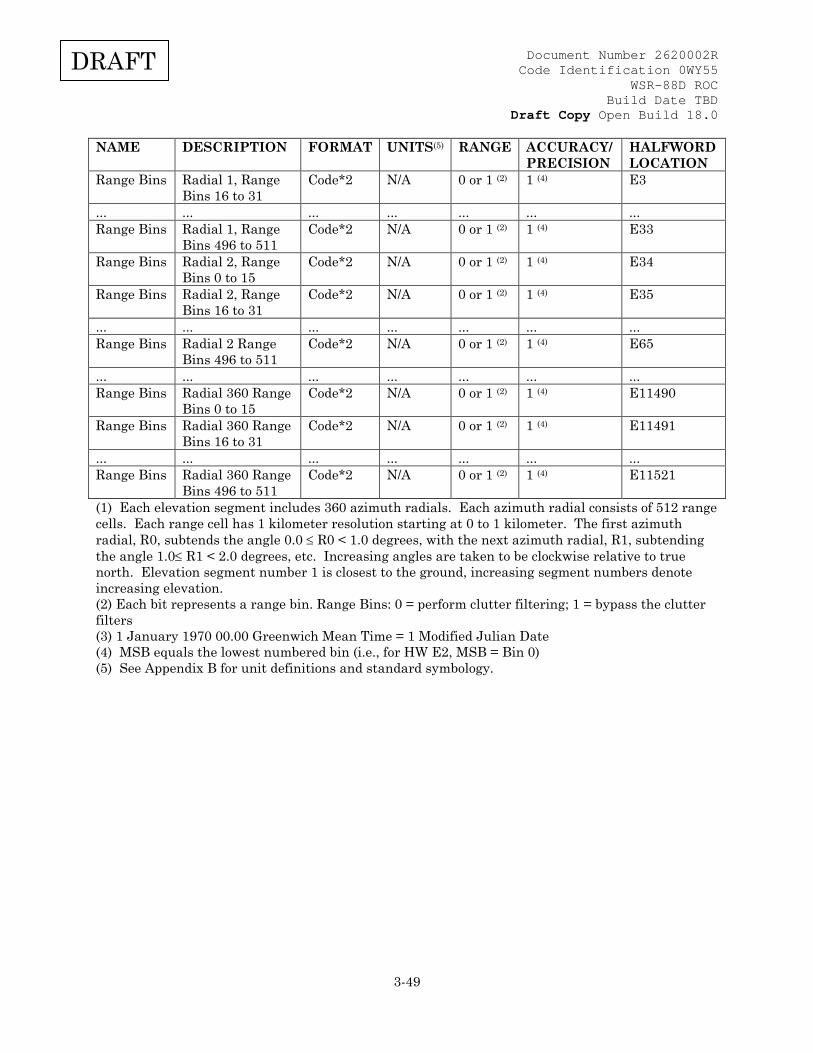
Document Number 2620002R Code Identification 0WY55
WSR-88D ROC Build Date TBD
Draft Copy Open Build 18.0
3-49
DRAFT
NAME DESCRIPTION FORMAT UNITS(5) RANGE ACCURACY/ PRECISION
HALFWORD LOCATION
Range Bins Radial 1, Range Bins 16 to 31
Code*2 N/A 0 or 1 (2) 1 (4) E3
... ... ... ... ... ... ... Range Bins Radial 1, Range
Bins 496 to 511 Code*2 N/A 0 or 1 (2) 1 (4) E33
Range Bins Radial 2, Range Bins 0 to 15
Code*2 N/A 0 or 1 (2) 1 (4) E34
Range Bins Radial 2, Range Bins 16 to 31
Code*2 N/A 0 or 1 (2) 1 (4) E35
... ... ... ... ... ... ... Range Bins Radial 2 Range
Bins 496 to 511 Code*2 N/A 0 or 1 (2) 1 (4) E65
... ... ... ... ... ... ... Range Bins Radial 360 Range
Bins 0 to 15 Code*2 N/A 0 or 1 (2) 1 (4) E11490
Range Bins Radial 360 Range Bins 16 to 31
Code*2 N/A 0 or 1 (2) 1 (4) E11491
... ... ... ... ... ... ... Range Bins Radial 360 Range
Bins 496 to 511 Code*2 N/A 0 or 1 (2) 1 (4) E11521
(1) Each elevation segment includes 360 azimuth radials. Each azimuth radial consists of 512 range cells. Each range cell has 1 kilometer resolution starting at 0 to 1 kilometer. The first azimuth radial, R0, subtends the angle 0.0 ≤ R0 < 1.0 degrees, with the next azimuth radial, R1, subtending the angle 1.0≤ R1 < 2.0 degrees, etc. Increasing angles are taken to be clockwise relative to true north. Elevation segment number 1 is closest to the ground, increasing segment numbers denote increasing elevation. (2) Each bit represents a range bin. Range Bins: 0 = perform clutter filtering; 1 = bypass the clutter filters (3) 1 January 1970 00.00 Greenwich Mean Time = 1 Modified Julian Date (4) MSB equals the lowest numbered bin (i.e., for HW E2, MSB = Bin 0) (5) See Appendix B for unit definitions and standard symbology.

Document Number 2620002R Code Identification 0WY55
WSR-88D ROC Build Date TBD
Draft Copy Open Build 18.0
3-50
DRAFT
3.2.4.11 Table X. RDA Control Commands (Message Type 6) Table X. RDA Control Commands (Message Type 6)
NAME DESCRIPTION FORMAT(2) UNITS(6) RANGE (OR VALUE)
ACCURACY/ PRECISION
HALFWORD LOCATION
RDA STATE COMMAND (1)
RDA State Command Values: •No Change •Stand-By •Offline Operate •Operate •Restart
Code*2
N/A As Listed •0 (no bits set) •32769 (bit 0 & 15 =1) •32770 (bit 1 & 15 =1) •32772 (bit 2 & 15 =1) •32776 (bit 3 & 15 =1)
N/A 1
SPARE Note (3)
N/A (CCR 08-00035)
N/A 2
AUXILIARY POWER GENERATOR CONTROL Note(4)
Aux. Power Generator Control Values: •No Change •Switch to Auxiliary Power •Switch to Utility Power
Code*2
N/A As Listed •0 (no bits set) •32772 (bit 2 & 15 =1) •32770 (bit 1 & 15 =1)
N/A 3
RDA CONTROL COMMANDS AND AUTHORIZATION
•No Change •Control Command Clear •Local Control Enabled •Remote Control Accepted •Remote Control Requested
Code*2 N/A As listed •0 (no bits set) •2 (bit 1 set) •4 (bit 2 set) •8 (bit 3 set) •16 (bit 4 set)
N/A 4

Document Number 2620002R Code Identification 0WY55
WSR-88D ROC Build Date TBD
Draft Copy Open Build 18.0
3-51
DRAFT
NAME DESCRIPTION FORMAT(2) UNITS(6) RANGE (OR VALUE)
ACCURACY/ PRECISION
HALFWORD LOCATION
RESTART VCP OR ELEVATION CUT
Restart VCP or Elevation Cut Values: •None •Restart Volume Coverage Pattern •Restart Elevation Cut
Code*2
N/A As Listed •0 (no bits set) •32768 (bit 15 = 1) •32768 + cut number (bit 15 = 1; set binary number of cut in bits 0 to 7)
N/A 5
SELECT LOCAL VCP NUMBER FOR NEXT VOLUME SCAN
•Use Remote Pattern •Pattern Number •No Change
Integer*2 N/A As Listed •0 (no bits set) •1 to 767 •32767
1 6
SPARE
7
SUPER RESOLUTION CONTROL
Values: •No change •Enable •Disable
Code*2 (4)
N/A As
Listed •0 (no bits set) •2 (bit 1 set) •4 (bit 2 set)
N/A 8
CLUTTER MITIGATION DECISION CONTROL
Values: •No change •Enable •Disable
Code*2 (4) N/A As Listed •0 (no bits set) •2 (bit 1 set) •4 (bit 2 set)
N/A 9

Document Number 2620002R Code Identification 0WY55
WSR-88D ROC Build Date TBD
Draft Copy Open Build 18.0
3-52
DRAFT
NAME DESCRIPTION FORMAT(2) UNITS(6) RANGE (OR VALUE)
ACCURACY/ PRECISION
HALFWORD LOCATION
AVSET CONTROL Values: •No change •Enable •Disable
Code*2 (4) N/A As Listed •0 (no bits set) •2 (bit 1 set) •4 (bit 2 set)
N/A 10
SPARE N/A N/A 11 CHANNEL CONTROL COMMAND
•No Change •Set to Controlling Channel •Set to Non-controlling Channel
Code*2 N/A As Listed •0 (no bits set) •1 (bit 0 set) •2 (bit 1 set)
N/A 12
PERFORMANCE CHECK CONTROL
No Change Force Performance Check
Code*2 N/A As Listed •0 (no bits set) 1 (bit 0 set)
N/A 13
SPARE N/A N/A N/A N/A N/A 14 to 20 SPOT BLANKING
•No Change •Enable Spot Blanking •Disable Spot Blanking
Code*2 N/A As Listed •0 (no bits set) •2 (bit 1 set) •4 (bit 2 set)
N/A 21
SPARE N/A N/A N/A N/A N/A 22 to 26 (1) Only one command is allowed at a time; except Restart, which is allowed with operational commands. (2) A halfword is defined to be 16 bits. All specified bit locations are referenced from 0 (the LSB) to 15 (the MSB). (3) As of RDA Build 14.0, the RDA will ignore any base data selection control commands. (4) The states are mutually exclusive. (5) The data in this field is stored as a scaled integer. The format is XX.YY. For example, -10.00 equals a value of -1000. A value of +0.25 would equal a value of 25. (6) See Appendix B for unit definitions and standard symbology.

Document Number 2620002R Code Identification 0WY55
WSR-88D ROC Build Date TBD
Draft Copy Open Build 18.0
3-53
DRAFT
3.2.4.12 Table XI. Volume Coverage Pattern Data (Message Types 5 & 7) Table XI. Volume Coverage Pattern Data (Message Types 5 & 7)
NAME DESCRIPTION FORMAT(4) UNITS (10)
RANGE (OR VALUE)(7)
ACCURACY/ PRECISION
HALFWORD LOCATION
MESSAGE SIZE Number of Halfwords in Message
Integer*2 halfword 23 to 594 1 1
PATTERN TYPE Constant Elevation Cut
Code*2 N/A As listed 2
N/A 2
PATTERN NUMBER Pattern Number Values: •Operational •Constant Elevation Types (11)
Integer*2 N/A See Appendix C for available VCPs
1 3
NUMBER OF ELEVATION CUTS
Number of elevation cuts in one complete volume scan
Integer*2 N/A 1 to 25 1 4
CLUTTER MAP GROUP NUMBER
Clutter map groups are not currently implemented.
Integer*2 N/A 1 to 2 (12) 1 5
DOPPLER VELOCITY RESOLUTION
Doppler Velocity Resolution Values: •0.5 •1.0
Code*1 m/s As Listed •2 (set bit 9) •4 (set bit 10)
N/A 6 (1)
PULSE WIDTH Pulse Width Values: •Short •Long
Code*1 N/A As listed •2 (set bit 1) •4 (set bit 2)
N/A 6 (2)
RESERVED(14) N/A N/A N/A N/A N/A 7 VCP SEQUENCING(14) VCP SEQUENCING
VALUES •Number of Elevations •Maximum SAILS Cuts •Sequence Active •Truncated VCP
Code*2(15) N/A Bits 0-4 Bits 5-6 Bit 13 set Bit 14 set
N/A 8

Document Number 2620002R Code Identification 0WY55
WSR-88D ROC Build Date TBD
Draft Copy Open Build 18.0
3-54
DRAFT
NAME DESCRIPTION FORMAT(4) UNITS (10)
RANGE (OR VALUE)(7)
ACCURACY/ PRECISION
HALFWORD LOCATION
VCP SUPPLEMENTAL DATA(14)
VCP SUPPLEMENTAL VALUES •SAILS VCP •Number SAILS Cuts •MRLE VCP •Number of MRLE Cuts
Code*2(15) N/A Bit 0 set Bits 1-3 Bit 4 set Bit 5-7
9
RESERVED(14) N/A N/A N/A N/A N/A 10 to 11 Repeat for each elevation angle (18) ELEVATION ANGLE (3) The elevation angle for this
cut Code*2 (6) deg 0.000000 to
359.956055 0.043945 E1
CHANNEL CONFIGURATION
Channel Configuration Values: •Constant Phase •Random Phase •SZ2 Phase
Code*1 N/A As Listed •0 •1 •2
N/A E2 (1)
WAVEFORM TYPE Waveform Type Values: •Contiguous Surveillance •Contiguous Doppler w/ Ambiguity Resolution •Contiguous Doppler w/o Ambiguity Resolution •Batch •Staggered Pulse Pair
Code*1 N/A As Listed (8)
•1 •2 •3 •4 •5
N/A E2 (2)
SUPER RESOLUTION CONTROL
Super Resolution Control Values:
• 0.5 degree azimuth • 1/4 km reflectivity
• Doppler to 300 km Dual Polarization Control • Dual Polarization to 300 km
Code*1 N/A As Listed (13)
• Bit 0 set • Bit 1 set
• Bit 2 set • Bit 3 set
N/A E3 (1)
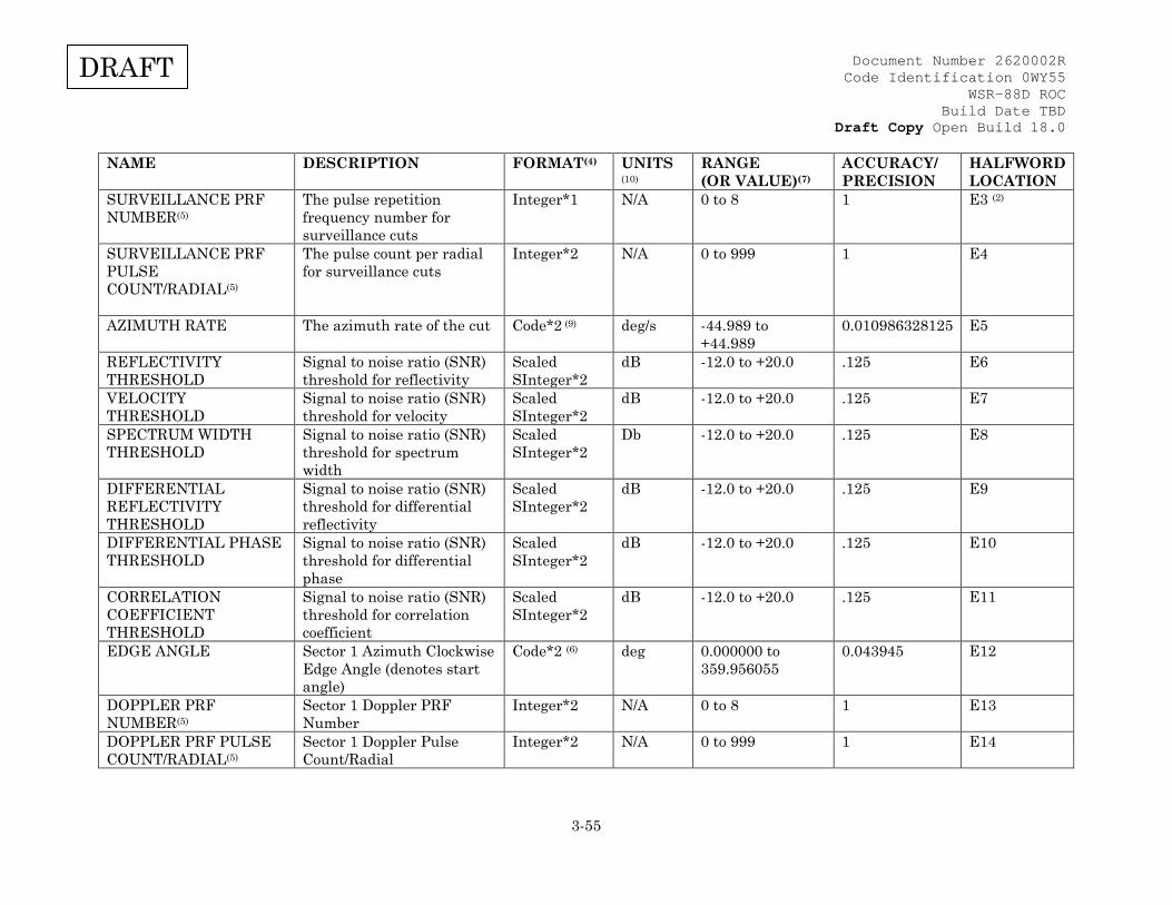
Document Number 2620002R Code Identification 0WY55
WSR-88D ROC Build Date TBD
Draft Copy Open Build 18.0
3-55
DRAFT
NAME DESCRIPTION FORMAT(4) UNITS (10)
RANGE (OR VALUE)(7)
ACCURACY/ PRECISION
HALFWORD LOCATION
SURVEILLANCE PRF NUMBER(5)
The pulse repetition frequency number for surveillance cuts
Integer*1 N/A 0 to 8 1 E3 (2)
SURVEILLANCE PRF PULSE COUNT/RADIAL(5)
The pulse count per radial for surveillance cuts
Integer*2 N/A 0 to 999 1 E4
AZIMUTH RATE The azimuth rate of the cut Code*2 (9) deg/s -44.989 to +44.989
0.010986328125 E5
REFLECTIVITY THRESHOLD
Signal to noise ratio (SNR) threshold for reflectivity
Scaled SInteger*2
dB -12.0 to +20.0 .125 E6
VELOCITY THRESHOLD
Signal to noise ratio (SNR) threshold for velocity
Scaled SInteger*2
dB -12.0 to +20.0 .125 E7
SPECTRUM WIDTH THRESHOLD
Signal to noise ratio (SNR) threshold for spectrum width
Scaled SInteger*2
Db -12.0 to +20.0 .125 E8
DIFFERENTIAL REFLECTIVITY THRESHOLD
Signal to noise ratio (SNR) threshold for differential reflectivity
Scaled SInteger*2
dB -12.0 to +20.0 .125 E9
DIFFERENTIAL PHASE THRESHOLD
Signal to noise ratio (SNR) threshold for differential phase
Scaled SInteger*2
dB -12.0 to +20.0 .125 E10
CORRELATION COEFFICIENT THRESHOLD
Signal to noise ratio (SNR) threshold for correlation coefficient
Scaled SInteger*2
dB -12.0 to +20.0 .125 E11
EDGE ANGLE Sector 1 Azimuth Clockwise Edge Angle (denotes start angle)
Code*2 (6) deg 0.000000 to 359.956055
0.043945 E12
DOPPLER PRF NUMBER(5)
Sector 1 Doppler PRF Number
Integer*2 N/A 0 to 8 1 E13
DOPPLER PRF PULSE COUNT/RADIAL(5)
Sector 1 Doppler Pulse Count/Radial
Integer*2 N/A 0 to 999 1 E14
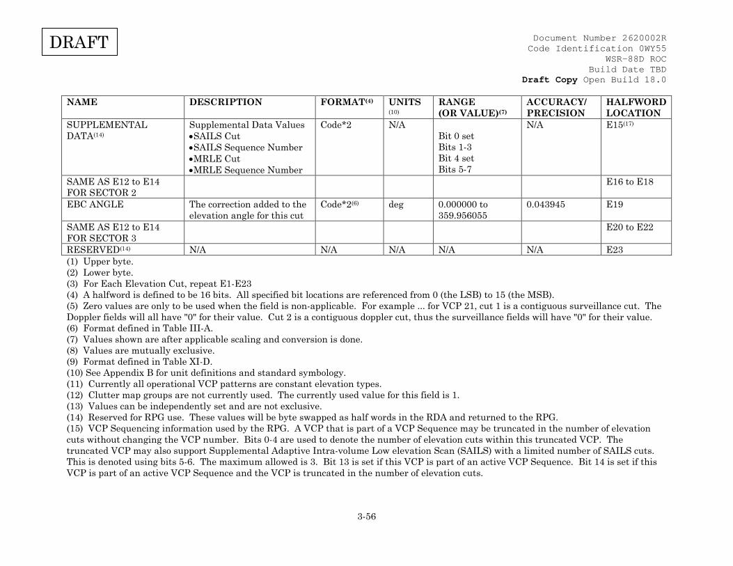
Document Number 2620002R Code Identification 0WY55
WSR-88D ROC Build Date TBD
Draft Copy Open Build 18.0
3-56
DRAFT
NAME DESCRIPTION FORMAT(4) UNITS (10)
RANGE (OR VALUE)(7)
ACCURACY/ PRECISION
HALFWORD LOCATION
SUPPLEMENTAL DATA(14)
Supplemental Data Values •SAILS Cut •SAILS Sequence Number •MRLE Cut •MRLE Sequence Number
Code*2 N/A Bit 0 set Bits 1-3 Bit 4 set Bits 5-7
N/A E15(17)
SAME AS E12 to E14 FOR SECTOR 2
E16 to E18
EBC ANGLE The correction added to the elevation angle for this cut
Code*2(6) deg 0.000000 to 359.956055
0.043945 E19
SAME AS E12 to E14 FOR SECTOR 3
E20 to E22
RESERVED(14) N/A N/A N/A N/A N/A E23 (1) Upper byte. (2) Lower byte. (3) For Each Elevation Cut, repeat E1-E23 (4) A halfword is defined to be 16 bits. All specified bit locations are referenced from 0 (the LSB) to 15 (the MSB). (5) Zero values are only to be used when the field is non-applicable. For example ... for VCP 21, cut 1 is a contiguous surveillance cut. The Doppler fields will all have "0" for their value. Cut 2 is a contiguous doppler cut, thus the surveillance fields will have "0" for their value. (6) Format defined in Table III-A. (7) Values shown are after applicable scaling and conversion is done. (8) Values are mutually exclusive. (9) Format defined in Table XI-D. (10) See Appendix B for unit definitions and standard symbology. (11) Currently all operational VCP patterns are constant elevation types. (12) Clutter map groups are not currently used. The currently used value for this field is 1. (13) Values can be independently set and are not exclusive. (14) Reserved for RPG use. These values will be byte swapped as half words in the RDA and returned to the RPG. (15) VCP Sequencing information used by the RPG. A VCP that is part of a VCP Sequence may be truncated in the number of elevation cuts without changing the VCP number. Bits 0-4 are used to denote the number of elevation cuts within this truncated VCP. The truncated VCP may also support Supplemental Adaptive Intra-volume Low elevation Scan (SAILS) with a limited number of SAILS cuts. This is denoted using bits 5-6. The maximum allowed is 3. Bit 13 is set if this VCP is part of an active VCP Sequence. Bit 14 is set if this VCP is part of an active VCP Sequence and the VCP is truncated in the number of elevation cuts.
Document Number 2620002R Code Identification 0WY55
WSR-88D ROC Build Date TBD
Draft Copy Open Build 18.0
3-57
DRAFT
(16) Supplemental Scan information used by the RPG. Bit 0 is set if this VCP contains SAILS cuts. Bits 1-3 are used to denote the number of SAILS cuts in the VCP limited to a maximum of 3. Bit 4 is set if this VCP contains Mid-volume Rescan of Low-level Elevations (MRLE) cuts. Bits 5-7 denote the number of MRLE cuts in the VCP limited to a maximum of 4. SAILS and MRLE cannot be simultaneously active. (17) This word defines information about whether the elevation cut is a SAILS or a MRLE cut. If a SAILS cut (bit 0 set), bits 1-3 denote the SAILS sequence number. If a MRLE cut (bit 4 set), bits 5-7 denote the MRLE sequence number. The MRLE sequence number will be the same as the RPG elevation index of the cut. By definition, the RPG elevation indexing scheme treats split cuts as the same elevation index. An elevation cut cannot be both a SAILS cut and a MRLE cut. (18) E value halfword locations are determined by EX = 12 + (X-1).
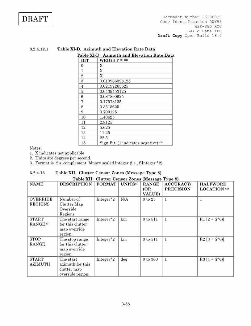
Document Number 2620002R Code Identification 0WY55
WSR-88D ROC Build Date TBD
Draft Copy Open Build 18.0
3-58
DRAFT
3.2.4.12.1 Table XI-D. Azimuth and Elevation Rate Data Table XI-D. Azimuth and Elevation Rate Data
BIT WEIGHT (1) (2) 0 X 1 X 2 X 3 0.010986328125 4 0.02197265625 5 0.0439453125 6 0.087890625 7 0.17578125 8 0.3515625 9 0.703125 10 1.40625 11 2.8125 12 5.625 13 11.25 14 22.5 15 Sign Bit (1 indicates negative) (3)
Notes: 1. X indicates not applicable 2. Units are degrees per second. 3. Format is 2's complement binary scaled integer (i.e., SInteger *2)
3.2.4.13 Table XII. Clutter Censor Zones (Message Type 8) Table XII. Clutter Censor Zones (Message Type 8)
NAME DESCRIPTION FORMAT UNITS(3) RANGE (OR VALUE)
ACCURACY/ PRECISION
HALFWORD LOCATION (2)
OVERRIDE REGIONS
Number of Clutter Map Override Regions
Integer*2 N/A 0 to 25 1 1
START RANGE (1)
The start range for this clutter map override region.
Integer*2 km 0 to 511 1 R1 [2 + (i*6)]
STOP RANGE
The stop range for this clutter map override region.
Integer*2 km 0 to 511 1 R2 [3 + (i*6)]
START AZIMUTH
The start azimuth for this clutter map override region.
Integer*2 deg 0 to 360 1 R3 [4 + (i*6)]

Document Number 2620002R Code Identification 0WY55
WSR-88D ROC Build Date TBD
Draft Copy Open Build 18.0
3-59
DRAFT
NAME DESCRIPTION FORMAT UNITS(3) RANGE (OR VALUE)
ACCURACY/ PRECISION
HALFWORD LOCATION (2)
STOP AZIMUTH
The stop azimuth for this clutter map override region.
Integer*2 deg 0 to 360 1 R4 [5 + (i*6)]
ELEVATION SEGMENT NUMBER
Elevation segment 1 is closest to the ground, increasing segment number denotes increasing elevation.
Integer*2 N/A 1 to 5 1 R5 [6 + (i*6)]
OPERATOR SELECT CODE
•Bypass Filter Forced (no filtering) •Bypass Map in Control •Clutter Filtering Forced
Code*2 N/A As Listed •0 •1 •2
N/A R6 [7 + (i*6)]
Notes: 1. For each subsequent region, halfwords R1 through R6 shall be repeated. For example, region 0 will use halfwords 2 through 7, region 1 will use halfwords 8 through 13, region 2 will use halfwords 14 through 19, etc. 2. Where "i" is used, i = override region number (0-based). 3. See Appendix B for unit definitions and standard symbology.

Document Number 2620002R Code Identification 0WY55
WSR-88D ROC Build Date TBD
Draft Copy Open Build 18.0
3-60
DRAFT
3.2.4.14 Table XIII. Request for Data (Message Type 9) Table XIII. Request for Data (Message Type 9)
NAME DESCRIPTION FORMAT (1)
UNITS RANGE (OR VALUE)
ACCURACY/ PRECISION
HALFWORD LOCATION
Data Request Type
•Request Summary RDA Status •Request RDA Performance/Maintenance Data •Request Clutter Filter Bypass Map •Request Clutter Filter Map •Request RDA Adaptation Data •Request Volume Coverage Pattern Data
Code*2 N/A As Listed •129 (bits 0&7=1) •130 (bits 1&7=1) •132 (bits 2&7=1) •136 (bits 3&7=1) •144 (bits 4&7=1) •160 (bits 5&7=1)
N/A 1
Notes: 1. LSB = bit 0
3.2.4.15 Table XIV. Clutter Filter Map (Message Type 15) Table XIV. Clutter Filter Map (Message Type 15)
NAME DESCRIPTION FORMAT UNITS(5) RANGE (OR VALUE)
ACCURACY /PRECISION
HALFWORD LOCATION
Map Generation Date
Julian Date - 2440586.5 (1)
Integer*2 d 1 to 65535
1 1
Map Generation Time
Number of Minutes since Midnight Greenwich Mean Time
Integer*2 min 0 to 1440 1 2
Number of Elevation Segments
Number of elevation segments in map.
Integer*2 N/A 1 to 5 1 3
Repeat for each Elevation Segment (2) Repeat for each Azimuth Segment (3) Number of Range Zones
Number of defined range zones for this azimuth.
Integer*2 N/A 1 to 20 1 A1
Range Zone (4)

Document Number 2620002R Code Identification 0WY55
WSR-88D ROC Build Date TBD
Draft Copy Open Build 18.0
3-61
DRAFT
NAME DESCRIPTION FORMAT UNITS(5) RANGE (OR VALUE)
ACCURACY /PRECISION
HALFWORD LOCATION
Op Code Bypass Filter Bypass map in Control Force Filter
Code*2 N/A As Listed 0 1 2
N/A R1
End Range (4)
Stop Range per Zone
Integer*2 km 0 to 511 1 R2
Same as R1 & R2 for Range Zone 1
... ... ... ... ... ... ... Same as R1 & R2 for # of Range Zones specified
Notes: 1. 1 January 1970 00.00 Greenwich Mean Time = 1 Modified Julian Date 2. There can be up to 5 elevation segments. Typically, only 2 elevation segments are used. The first elevation segment is closest to the ground, increasing segment numbers denote increasing elevation. 3. There are 360 azimuth segments (segment 0 through segment 359). The first azimuth radial, R0, subtends the angle (0.0 ≤ R0 < 1.0) degrees, with the next azimuth radial, R1, subtending the angle (1.0 ≤ R1 < 2.0) degrees, etc. Increasing angles are taken to be clockwise relative to true north. 4. There are 20 possible range zones. Not all range zones need to be defined. The last range zone must have end range of 511. 5. See Appendix B for unit definitions and standard symbology.
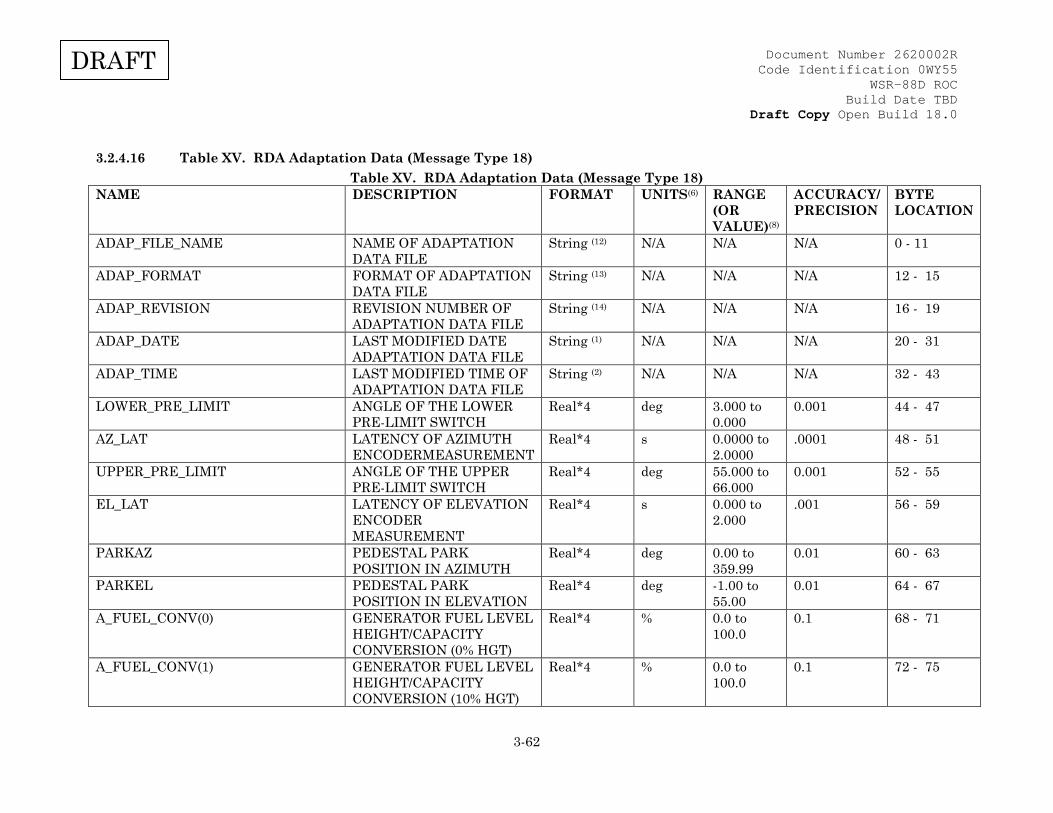
Document Number 2620002R Code Identification 0WY55
WSR-88D ROC Build Date TBD
Draft Copy Open Build 18.0
3-62
DRAFT
3.2.4.16 Table XV. RDA Adaptation Data (Message Type 18) Table XV. RDA Adaptation Data (Message Type 18)
NAME DESCRIPTION FORMAT UNITS(6) RANGE (OR VALUE)(8)
ACCURACY/ PRECISION
BYTE LOCATION
ADAP_FILE_NAME NAME OF ADAPTATION DATA FILE
String (12) N/A N/A N/A 0 - 11
ADAP_FORMAT FORMAT OF ADAPTATION DATA FILE
String (13) N/A N/A N/A 12 - 15
ADAP_REVISION REVISION NUMBER OF ADAPTATION DATA FILE
String (14) N/A N/A N/A 16 - 19
ADAP_DATE LAST MODIFIED DATE ADAPTATION DATA FILE
String (1) N/A N/A N/A 20 - 31
ADAP_TIME LAST MODIFIED TIME OF ADAPTATION DATA FILE
String (2) N/A N/A N/A 32 - 43
LOWER_PRE_LIMIT ANGLE OF THE LOWER PRE-LIMIT SWITCH
Real*4 deg 3.000 to 0.000
0.001 44 - 47
AZ_LAT LATENCY OF AZIMUTH ENCODERMEASUREMENT
Real*4 s 0.0000 to 2.0000
.0001 48 - 51
UPPER_PRE_LIMIT ANGLE OF THE UPPER PRE-LIMIT SWITCH
Real*4 deg 55.000 to 66.000
0.001 52 - 55
EL_LAT LATENCY OF ELEVATION ENCODER MEASUREMENT
Real*4 s 0.000 to 2.000
.001 56 - 59
PARKAZ PEDESTAL PARK POSITION IN AZIMUTH
Real*4 deg 0.00 to 359.99
0.01 60 - 63
PARKEL PEDESTAL PARK POSITION IN ELEVATION
Real*4 deg -1.00 to 55.00
0.01 64 - 67
A_FUEL_CONV(0) GENERATOR FUEL LEVEL HEIGHT/CAPACITY CONVERSION (0% HGT)
Real*4 % 0.0 to 100.0
0.1 68 - 71
A_FUEL_CONV(1) GENERATOR FUEL LEVEL HEIGHT/CAPACITY CONVERSION (10% HGT)
Real*4 % 0.0 to 100.0
0.1 72 - 75

Document Number 2620002R Code Identification 0WY55
WSR-88D ROC Build Date TBD
Draft Copy Open Build 18.0
3-63
DRAFT
NAME DESCRIPTION FORMAT UNITS(6) RANGE (OR VALUE)(8)
ACCURACY/ PRECISION
BYTE LOCATION
A_FUEL_CONV(2) GENERATOR FUEL LEVEL HEIGHT/CAPACITY CONVERSION (20% HGT)
Real*4 % 0.0 to 100.0
0.1 76 - 79
A_FUEL_CONV(3) GENERATOR FUEL LEVEL HEIGHT/CAPACITY CONVERSION (30% HGT)
Real*4 % 0.0 to 100.0
0.1 80 - 83
A_FUEL_CONV(4) GENERATOR FUEL LEVEL HEIGHT/CAPACITY CONVERSION (40% HGT)
Real*4 % 0.0 to 100.0
0.1 84 - 87
A_FUEL_CONV(5) GENERATOR FUEL LEVEL HEIGHT/CAPACITY CONVERSION (50% HGT)
Real*4 % 0.0 to 100.0
0.1 88 - 91
A_FUEL_CONV(6) GENERATOR FUEL LEVEL HEIGHT/CAPACITY CONVERSION (60% HGT)
Real*4 % 0.0 to 100.0
0.1 92 - 95
A_FUEL_CONV(7) GENERATOR FUEL LEVEL HEIGHT/CAPACITY CONVERSION (70% HGT)
Real*4 % 0.0 to 100.0
0.1 96 - 99
A_FUEL_CONV(8) GENERATOR FUEL LEVEL HEIGHT/CAPACITY CONVERSION (80% HGT)
Real*4 % 0.0 to 100.0
0.1 100 - 103
A_FUEL_CONV(9) GENERATOR FUEL LEVEL HEIGHT/CAPACITY CONVERSION (90% HGT)
Real*4 % 0.0 to 100.0
0.1 104 - 107
A_FUEL_CONV(10) GENERATOR FUEL LEVEL HEIGHT/CAPACITY CONVERSION (100% HGT)
Real*4 % 0.0 to 100.0
0.1 108 - 111
A_MIN_SHELTER_TEMP MINIMUM EQUIPMENT SHELTER ALARM TEMPERATURE
Real*4 deg C 0.0 to 50.0 0.1 112 - 115

Document Number 2620002R Code Identification 0WY55
WSR-88D ROC Build Date TBD
Draft Copy Open Build 18.0
3-64
DRAFT
NAME DESCRIPTION FORMAT UNITS(6) RANGE (OR VALUE)(8)
ACCURACY/ PRECISION
BYTE LOCATION
A_MAX_SHELTER_TEMP MAXIMUM EQUIPMENT SHELTER ALARM TEMPERATURE
Real*4 deg C 0.0 to 50.0 0.1 116 - 119
A_MIN_SHELTER_AC_TEMP_DIFF MINIMUM A/C DISCHARGE AIR TEMPERATURE DIFFERENTIAL
Real*4 deg C 0.0 to 10.0 0.1 120 - 123
A_MAX_XMTR_AIR_TEMP MAXIMUM TRANSMITTER LEAVING AIR ALARM TEMPERATURE
Real*4 deg C 0.0 to 55.0 0.1 124 - 127
A_MAX_RAD_TEMP MAXIMUM RADOME ALARM TEMPERATURE
Real*4 deg C 0.0 to 50.0 0.1 128 - 131
A_MAX_RAD_TEMP_RISE MAXIMUM RADOME MINUS AMBIENT TEMPERATURE DIFFERENCE
Real*4 deg C 0.0 to 10.0 0.1 132 - 135
LOWER_DEAD_LIMIT ANGLE OF LOWER DEAD LIMIT SWITCH
Real*4 deg 4.000 to 0.000
0.001 136 - 139
UPPER_DEAD_LIMIT ANGLE OF THE UPPER DEAD LIMIT SWITCH
Real*4 deg 60.000 to 66.000
0.001 140 - 143
SPARE N/A N/A N/A N/A N/A 144 - 147 A_MIN_GEN_ROOM_TEMP MINIMUM GENERATOR
SHELTER ALARM TEMPERATURE
Real*4 deg C 0.0 to 50.0 0.1 148 - 151
A_MAX_GEN_ROOM_TEMP MAXIMUM GENERATOR SHELTER ALARM TEMPERATURE
Real*4 deg C 0.0 to 50.0 0.1 152 - 155
SPIP_5V_REG_LIM SPIP +5 VOLT POWER SUPPLY TOLERANCE
Real*4 % 0.0 to 20.0 0.1 156 - 159
SPIP_15V_REG_LIM SPIP +/- 15 VOLT POWER SUPPLY TOLERANCE
Real*4 % 0.0 to 20.0 0.1 160 - 163
SPARE N/A N/A N/A N/A N/A 164 - 175
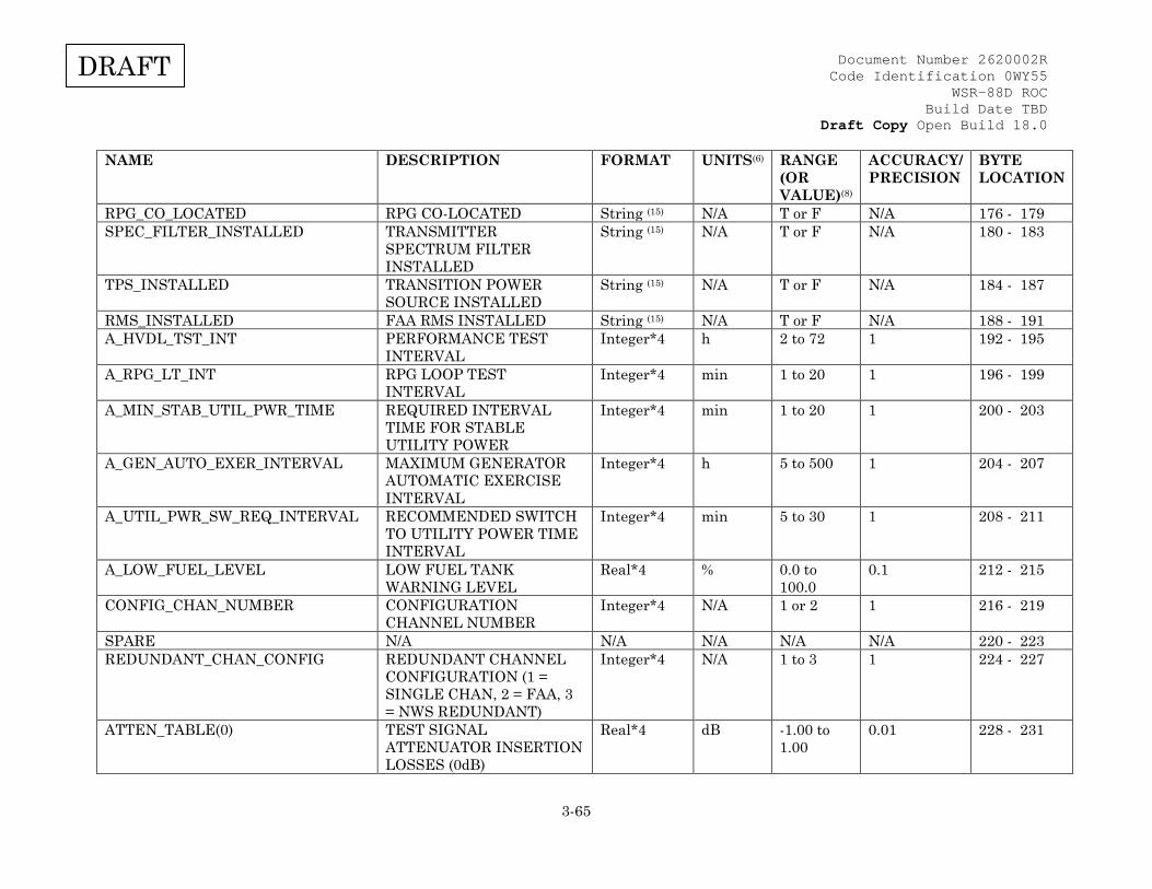
Document Number 2620002R Code Identification 0WY55
WSR-88D ROC Build Date TBD
Draft Copy Open Build 18.0
3-65
DRAFT
NAME DESCRIPTION FORMAT UNITS(6) RANGE (OR VALUE)(8)
ACCURACY/ PRECISION
BYTE LOCATION
RPG_CO_LOCATED RPG CO-LOCATED String (15) N/A T or F N/A 176 - 179 SPEC_FILTER_INSTALLED TRANSMITTER
SPECTRUM FILTER INSTALLED
String (15) N/A T or F N/A 180 - 183
TPS_INSTALLED TRANSITION POWER SOURCE INSTALLED
String (15) N/A T or F N/A 184 - 187
RMS_INSTALLED FAA RMS INSTALLED String (15) N/A T or F N/A 188 - 191 A_HVDL_TST_INT PERFORMANCE TEST
INTERVAL Integer*4 h 2 to 72 1 192 - 195
A_RPG_LT_INT RPG LOOP TEST INTERVAL
Integer*4 min 1 to 20 1 196 - 199
A_MIN_STAB_UTIL_PWR_TIME REQUIRED INTERVAL TIME FOR STABLE UTILITY POWER
Integer*4 min 1 to 20 1 200 - 203
A_GEN_AUTO_EXER_INTERVAL MAXIMUM GENERATOR AUTOMATIC EXERCISE INTERVAL
Integer*4 h 5 to 500 1 204 - 207
A_UTIL_PWR_SW_REQ_INTERVAL RECOMMENDED SWITCH TO UTILITY POWER TIME INTERVAL
Integer*4 min 5 to 30 1 208 - 211
A_LOW_FUEL_LEVEL LOW FUEL TANK WARNING LEVEL
Real*4 % 0.0 to 100.0
0.1 212 - 215
CONFIG_CHAN_NUMBER CONFIGURATION CHANNEL NUMBER
Integer*4 N/A 1 or 2 1 216 - 219
SPARE N/A N/A N/A N/A N/A 220 - 223 REDUNDANT_CHAN_CONFIG REDUNDANT CHANNEL
CONFIGURATION (1 = SINGLE CHAN, 2 = FAA, 3 = NWS REDUNDANT)
Integer*4 N/A 1 to 3 1 224 - 227
ATTEN_TABLE(0) TEST SIGNAL ATTENUATOR INSERTION LOSSES (0dB)
Real*4 dB -1.00 to 1.00
0.01 228 - 231
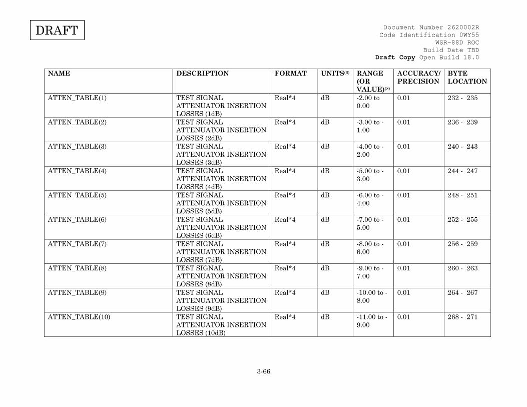
Document Number 2620002R Code Identification 0WY55
WSR-88D ROC Build Date TBD
Draft Copy Open Build 18.0
3-66
DRAFT
NAME DESCRIPTION FORMAT UNITS(6) RANGE (OR VALUE)(8)
ACCURACY/ PRECISION
BYTE LOCATION
ATTEN_TABLE(1) TEST SIGNAL ATTENUATOR INSERTION LOSSES (1dB)
Real*4 dB -2.00 to 0.00
0.01 232 - 235
ATTEN_TABLE(2) TEST SIGNAL ATTENUATOR INSERTION LOSSES (2dB)
Real*4 dB -3.00 to -1.00
0.01 236 - 239
ATTEN_TABLE(3) TEST SIGNAL ATTENUATOR INSERTION LOSSES (3dB)
Real*4 dB -4.00 to -2.00
0.01 240 - 243
ATTEN_TABLE(4) TEST SIGNAL ATTENUATOR INSERTION LOSSES (4dB)
Real*4 dB -5.00 to -3.00
0.01 244 - 247
ATTEN_TABLE(5) TEST SIGNAL ATTENUATOR INSERTION LOSSES (5dB)
Real*4 dB -6.00 to -4.00
0.01 248 - 251
ATTEN_TABLE(6) TEST SIGNAL ATTENUATOR INSERTION LOSSES (6dB)
Real*4 dB -7.00 to -5.00
0.01 252 - 255
ATTEN_TABLE(7) TEST SIGNAL ATTENUATOR INSERTION LOSSES (7dB)
Real*4 dB -8.00 to -6.00
0.01 256 - 259
ATTEN_TABLE(8) TEST SIGNAL ATTENUATOR INSERTION LOSSES (8dB)
Real*4 dB -9.00 to -7.00
0.01 260 - 263
ATTEN_TABLE(9) TEST SIGNAL ATTENUATOR INSERTION LOSSES (9dB)
Real*4 dB -10.00 to -8.00
0.01 264 - 267
ATTEN_TABLE(10) TEST SIGNAL ATTENUATOR INSERTION LOSSES (10dB)
Real*4 dB -11.00 to -9.00
0.01 268 - 271

Document Number 2620002R Code Identification 0WY55
WSR-88D ROC Build Date TBD
Draft Copy Open Build 18.0
3-67
DRAFT
NAME DESCRIPTION FORMAT UNITS(6) RANGE (OR VALUE)(8)
ACCURACY/ PRECISION
BYTE LOCATION
ATTEN_TABLE(11) TEST SIGNAL ATTENUATOR INSERTION LOSSES (11dB)
Real*4 dB -12.00 to -10.00
0.01 272 - 275
ATTEN_TABLE(12) TEST SIGNAL ATTENUATOR INSERTION LOSSES (12dB)
Real*4 dB -13.00 to -11.00
0.01 276 - 279
ATTEN_TABLE(13) TEST SIGNAL ATTENUATOR INSERTION LOSSES (13dB)
Real*4 dB -14.00 to -12.00
0.01 280 - 283
ATTEN_TABLE(14) TEST SIGNAL ATTENUATOR INSERTION LOSSES (14dB)
Real*4 dB -15.00 to -13.00
0.01 284 - 287
ATTEN_TABLE(15) TEST SIGNAL ATTENUATOR INSERTION LOSSES (15dB)
Real*4 dB -16.00 to -14.00
0.01 288 - 291
ATTEN_TABLE(16) TEST SIGNAL ATTENUATOR INSERTION LOSSES (16dB)
Real*4 dB -17.00 to -15.00
0.01 292 - 295
ATTEN_TABLE(17) TEST SIGNAL ATTENUATOR INSERTION LOSSES (17dB)
Real*4 dB -18.00 to -16.00
0.01 296 - 299
ATTEN_TABLE(18) TEST SIGNAL ATTENUATOR INSERTION LOSSES (18dB)
Real*4 dB -19.00 to -17.00
0.01 300 - 303
ATTEN_TABLE(19) TEST SIGNAL ATTENUATOR INSERTION LOSSES (19dB)
Real*4 dB -20.00 to -18.00
0.01 304 - 307
ATTEN_TABLE(20) TEST SIGNAL ATTENUATOR INSERTION LOSSES (20dB)
Real*4 dB -21.00 to -19.00
0.01 308 - 311

Document Number 2620002R Code Identification 0WY55
WSR-88D ROC Build Date TBD
Draft Copy Open Build 18.0
3-68
DRAFT
NAME DESCRIPTION FORMAT UNITS(6) RANGE (OR VALUE)(8)
ACCURACY/ PRECISION
BYTE LOCATION
ATTEN_TABLE(21) TEST SIGNAL ATTENUATOR INSERTION LOSSES (21dB)
Real*4 dB -22.00 to -20.00
0.01 312 - 315
ATTEN_TABLE(22) TEST SIGNAL ATTENUATOR INSERTION LOSSES (22dB)
Real*4 dB -23.00 to -21.00
0.01 316 - 319
ATTEN_TABLE(23) TEST SIGNAL ATTENUATOR INSERTION LOSSES (23dB)
Real*4 dB -24.00 to -22.00
0.01 320 - 323
ATTEN_TABLE(24) TEST SIGNAL ATTENUATOR INSERTION LOSSES (24dB)
Real*4 dB -25.00 to -23.00
0.01 324 - 327
ATTEN_TABLE(25) TEST SIGNAL ATTENUATOR INSERTION LOSSES (25dB)
Real*4 dB -26.00 to -24.00
0.01 328 - 331
ATTEN_TABLE(26) TEST SIGNAL ATTENUATOR INSERTION LOSSES (26dB)
Real*4 dB -27.00 to -25.00
0.01 332 - 335
ATTEN_TABLE(27) TEST SIGNAL ATTENUATOR INSERTION LOSSES (27dB)
Real*4 dB -28.00 to -26.00
0.01 336 - 339
ATTEN_TABLE(28) TEST SIGNAL ATTENUATOR INSERTION LOSSES (28dB)
Real*4 dB -29.00 to -27.00
0.01 340 - 343
ATTEN_TABLE(29) TEST SIGNAL ATTENUATOR INSERTION LOSSES (29dB)
Real*4 dB -30.00 to -28.00
0.01 344 - 347
ATTEN_TABLE(30) TEST SIGNAL ATTENUATOR INSERTION LOSSES (30dB)
Real*4 dB -31.00 to -29.00
0.01 348 - 351

Document Number 2620002R Code Identification 0WY55
WSR-88D ROC Build Date TBD
Draft Copy Open Build 18.0
3-69
DRAFT
NAME DESCRIPTION FORMAT UNITS(6) RANGE (OR VALUE)(8)
ACCURACY/ PRECISION
BYTE LOCATION
ATTEN_TABLE(31) TEST SIGNAL ATTENUATOR INSERTION LOSSES (31dB)
Real*4 dB -32.00 to -30.00
0.01 352 - 355
ATTEN_TABLE(32) TEST SIGNAL ATTENUATOR INSERTION LOSSES (32dB)
Real*4 dB -33.00 to -31.00
0.01 356 - 359
ATTEN_TABLE(33) TEST SIGNAL ATTENUATOR INSERTION LOSSES (33dB)
Real*4 dB -34.00 to -32.00
0.01 360 - 363
ATTEN_TABLE(34) TEST SIGNAL ATTENUATOR INSERTION LOSSES (34dB)
Real*4 dB -35.00 to -33.00
0.01 364 - 367
ATTEN_TABLE(35) TEST SIGNAL ATTENUATOR INSERTION LOSSES (35dB)
Real*4 dB -36.00 to -34.00
0.01 368 - 371
ATTEN_TABLE(36) TEST SIGNAL ATTENUATOR INSERTION LOSSES (36dB)
Real*4 dB -37.00 to -35.00
0.01 372 - 375
ATTEN_TABLE(37) TEST SIGNAL ATTENUATOR INSERTION LOSSES (37dB)
Real*4 dB -38.00 to -36.00
0.01 376 - 379
ATTEN_TABLE(38) TEST SIGNAL ATTENUATOR INSERTION LOSSES (38dB)
Real*4 dB -39.00 to -37.00
0.01 380 - 383
ATTEN_TABLE(39) TEST SIGNAL ATTENUATOR INSERTION LOSSES (39dB)
Real*4 dB -40.00 to -38.00
0.01 384 - 387
ATTEN_TABLE(40) TEST SIGNAL ATTENUATOR INSERTION LOSSES (40dB)
Real*4 dB -41.00 to -39.00
0.01 388 - 391

Document Number 2620002R Code Identification 0WY55
WSR-88D ROC Build Date TBD
Draft Copy Open Build 18.0
3-70
DRAFT
NAME DESCRIPTION FORMAT UNITS(6) RANGE (OR VALUE)(8)
ACCURACY/ PRECISION
BYTE LOCATION
ATTEN_TABLE(41) TEST SIGNAL ATTENUATOR INSERTION LOSSES (41dB)
Real*4 dB -42.00 to -40.00
0.01 392 - 395
ATTEN_TABLE(42) TEST SIGNAL ATTENUATOR INSERTION LOSSES (42dB)
Real*4 dB -43.00 to -41.00
0.01 396 - 399
ATTEN_TABLE(43) TEST SIGNAL ATTENUATOR INSERTION LOSSES (43dB)
Real*4 dB -44.00 to -42.00
0.01 400 - 403
ATTEN_TABLE(44) TEST SIGNAL ATTENUATOR INSERTION LOSSES (44dB)
Real*4 dB -45.00 to -43.00
0.01 404 - 407
ATTEN_TABLE(45) TEST SIGNAL ATTENUATOR INSERTION LOSSES (45dB)
Real*4 dB -46.00 to -44.00
0.01 408 - 411
ATTEN_TABLE(46) TEST SIGNAL ATTENUATOR INSERTION LOSSES (46dB)
Real*4 dB -47.00 to -45.00
0.01 412 - 415
ATTEN_TABLE(47) TEST SIGNAL ATTENUATOR INSERTION LOSSES (47dB)
Real*4 dB -48.00 to -46.00
0.01 416 - 419
ATTEN_TABLE(48) TEST SIGNAL ATTENUATOR INSERTION LOSSES (48dB)
Real*4 dB -49.00 to -47.00
0.01 420 - 423
ATTEN_TABLE(49) TEST SIGNAL ATTENUATOR INSERTION LOSSES (49dB)
Real*4 dB -50.00 to -48.00
0.01 424 - 427
ATTEN_TABLE(50) TEST SIGNAL ATTENUATOR INSERTION LOSSES (50dB)
Real*4 dB -51.00 to -49.00
0.01 428 - 431

Document Number 2620002R Code Identification 0WY55
WSR-88D ROC Build Date TBD
Draft Copy Open Build 18.0
3-71
DRAFT
NAME DESCRIPTION FORMAT UNITS(6) RANGE (OR VALUE)(8)
ACCURACY/ PRECISION
BYTE LOCATION
ATTEN_TABLE(51) TEST SIGNAL ATTENUATOR INSERTION LOSSES (51dB)
Real*4 dB -52.00 to -50.00
0.01 432 - 435
ATTEN_TABLE(52) TEST SIGNAL ATTENUATOR INSERTION LOSSES (52dB)
Real*4 dB -53.00 to -51.00
0.01 436 - 439
ATTEN_TABLE(53) TEST SIGNAL ATTENUATOR INSERTION LOSSES (53dB)
Real*4 dB -54.00 to -52.00
0.01 440 - 443
ATTEN_TABLE(54) TEST SIGNAL ATTENUATOR INSERTION LOSSES (54dB)
Real*4 dB -55.00 to -53.00
0.01 444 - 447
ATTEN_TABLE(55) TEST SIGNAL ATTENUATOR INSERTION LOSSES (55dB)
Real*4 dB -56.00 to -54.00
0.01 448 - 451
ATTEN_TABLE(56) TEST SIGNAL ATTENUATOR INSERTION LOSSES (56dB)
Real*4 dB -57.00 to -55.00
0.01 452 - 455
ATTEN_TABLE(57) TEST SIGNAL ATTENUATOR INSERTION LOSSES (57dB)
Real*4 dB -58.00 to -56.00
0.01 456 - 459
ATTEN_TABLE(58) TEST SIGNAL ATTENUATOR INSERTION LOSSES (58dB)
Real*4 dB -59.00 to -57.00
0.01 460 - 463
ATTEN_TABLE(59) TEST SIGNAL ATTENUATOR INSERTION LOSSES (59dB)
Real*4 dB -60.00 to -58.00
0.01 464 - 467
ATTEN_TABLE(60) TEST SIGNAL ATTENUATOR INSERTION LOSSES (60dB)
Real*4 dB -61.00 to -59.00
0.01 468 - 471

Document Number 2620002R Code Identification 0WY55
WSR-88D ROC Build Date TBD
Draft Copy Open Build 18.0
3-72
DRAFT
NAME DESCRIPTION FORMAT UNITS(6) RANGE (OR VALUE)(8)
ACCURACY/ PRECISION
BYTE LOCATION
ATTEN_TABLE(61) TEST SIGNAL ATTENUATOR INSERTION LOSSES (61dB)
Real*4 dB -62.00 to -60.00
0.01 472 - 475
ATTEN_TABLE(62) TEST SIGNAL ATTENUATOR INSERTION LOSSES (62dB)
Real*4 dB -63.00 to -61.00
0.01 476 - 479
ATTEN_TABLE(63) TEST SIGNAL ATTENUATOR INSERTION LOSSES (63dB)
Real*4 dB -64.00 to -62.00
0.01 480 - 483
ATTEN_TABLE(64) TEST SIGNAL ATTENUATOR INSERTION LOSSES (64dB)
Real*4 dB -65.00 to -63.00
0.01 484 - 487
ATTEN_TABLE(65) TEST SIGNAL ATTENUATOR INSERTION LOSSES (65dB)
Real*4 dB -66.00 to -64.00
0.01 488 - 491
ATTEN_TABLE(66) TEST SIGNAL ATTENUATOR INSERTION LOSSES (66dB)
Real*4 dB -67.00 to -65.00
0.01 492 - 495
ATTEN_TABLE(67) TEST SIGNAL ATTENUATOR INSERTION LOSSES (67dB)
Real*4 dB -68.00 to -66.00
0.01 496 - 499
ATTEN_TABLE(68) TEST SIGNAL ATTENUATOR INSERTION LOSSES (68dB)
Real*4 dB -69.00 to -67.00
0.01 500 - 503
ATTEN_TABLE(69) TEST SIGNAL ATTENUATOR INSERTION LOSSES (69dB)
Real*4 dB -70.00 to -68.00
0.01 504 - 507
ATTEN_TABLE(70) TEST SIGNAL ATTENUATOR INSERTION LOSSES (70dB)
Real*4 dB -71.00 to -69.00
0.01 508 - 511

Document Number 2620002R Code Identification 0WY55
WSR-88D ROC Build Date TBD
Draft Copy Open Build 18.0
3-73
DRAFT
NAME DESCRIPTION FORMAT UNITS(6) RANGE (OR VALUE)(8)
ACCURACY/ PRECISION
BYTE LOCATION
ATTEN_TABLE(71) TEST SIGNAL ATTENUATOR INSERTION LOSSES (71dB)
Real*4 dB -72.00 to -70.00
0.01 512 - 515
ATTEN_TABLE(72) TEST SIGNAL ATTENUATOR INSERTION LOSSES (72dB)
Real*4 dB -73.00 to -71.00
0.01 516 - 519
ATTEN_TABLE(73) TEST SIGNAL ATTENUATOR INSERTION LOSSES (73dB)
Real*4 dB -74.00 to -72.00
0.01 520 - 523
ATTEN_TABLE(74) TEST SIGNAL ATTENUATOR INSERTION LOSSES (74dB)
Real*4 dB -75.00 to -73.00
0.01 524 - 527
ATTEN_TABLE(75) TEST SIGNAL ATTENUATOR INSERTION LOSSES (75dB)
Real*4 dB -76.00 to -74.00
0.01 528 - 531
ATTEN_TABLE(76) TEST SIGNAL ATTENUATOR INSERTION LOSSES (76dB)
Real*4 dB -77.00 to -75.00
0.01 532 - 535
ATTEN_TABLE(77) TEST SIGNAL ATTENUATOR INSERTION LOSSES (77dB)
Real*4 dB -78.00 to -76.00
0.01 536 - 539
ATTEN_TABLE(78) TEST SIGNAL ATTENUATOR INSERTION LOSSES (78dB)
Real*4 dB -79.00 to -77.00
0.01 540 - 543
ATTEN_TABLE(79) TEST SIGNAL ATTENUATOR INSERTION LOSSES (79dB)
Real*4 dB -80.00 to -78.00
0.01 544 - 547
ATTEN_TABLE(80) TEST SIGNAL ATTENUATOR INSERTION LOSSES (80dB)
Real*4 dB -81.00 to -79.00
0.01 548 - 551

Document Number 2620002R Code Identification 0WY55
WSR-88D ROC Build Date TBD
Draft Copy Open Build 18.0
3-74
DRAFT
NAME DESCRIPTION FORMAT UNITS(6) RANGE (OR VALUE)(8)
ACCURACY/ PRECISION
BYTE LOCATION
ATTEN_TABLE(81) TEST SIGNAL ATTENUATOR INSERTION LOSSES (81dB)
Real*4 dB -82.00 to -80.00
0.01 552 - 555
ATTEN_TABLE(82) TEST SIGNAL ATTENUATOR INSERTION LOSSES (82dB)
Real*4 dB -83.00 to -81.00
0.01 556 - 559
ATTEN_TABLE(83) TEST SIGNAL ATTENUATOR INSERTION LOSSES (83dB)
Real*4 dB -84.00 to -82.00
0.01 560 - 563
ATTEN_TABLE(84) TEST SIGNAL ATTENUATOR INSERTION LOSSES (84dB)
Real*4 dB -85.00 to -83.00
0.01 564 - 567
ATTEN_TABLE(85) TEST SIGNAL ATTENUATOR INSERTION LOSSES (85dB)
Real*4 dB -86.00 to -84.00
0.01 568 - 571
ATTEN_TABLE(86) TEST SIGNAL ATTENUATOR INSERTION LOSSES (86dB)
Real*4 dB -87.00 to -85.00
0.01 572 - 575
ATTEN_TABLE(87) TEST SIGNAL ATTENUATOR INSERTION LOSSES (87dB)
Real*4 dB -88.00 to -86.00
0.01 576 - 579
ATTEN_TABLE(88) TEST SIGNAL ATTENUATOR INSERTION LOSSES (88dB)
Real*4 dB -89.00 to -87.00
0.01 580 - 583
ATTEN_TABLE(89) TEST SIGNAL ATTENUATOR INSERTION LOSSES (89dB)
Real*4 dB -90.00 to -88.00
0.01 584 - 587
ATTEN_TABLE(90) TEST SIGNAL ATTENUATOR INSERTION LOSSES (90dB)
Real*4 dB -91.00 to -89.00
0.01 588 - 591

Document Number 2620002R Code Identification 0WY55
WSR-88D ROC Build Date TBD
Draft Copy Open Build 18.0
3-75
DRAFT
NAME DESCRIPTION FORMAT UNITS(6) RANGE (OR VALUE)(8)
ACCURACY/ PRECISION
BYTE LOCATION
ATTEN_TABLE(91) TEST SIGNAL ATTENUATOR INSERTION LOSSES (91dB)
Real*4 dB -92.00 to -90.00
0.01 592 - 595
ATTEN_TABLE(92) TEST SIGNAL ATTENUATOR INSERTION LOSSES (92dB)
Real*4 dB -93.00 to -91.00
0.01 596 - 599
ATTEN_TABLE(93) TEST SIGNAL ATTENUATOR INSERTION LOSSES (93dB)
Real*4 dB -94.00 to -92.00
0.01 600 - 603
ATTEN_TABLE(94) TEST SIGNAL ATTENUATOR INSERTION LOSSES (94dB)
Real*4 dB -95.00 to -93.00
0.01 604 - 607
ATTEN_TABLE(95) TEST SIGNAL ATTENUATOR INSERTION LOSSES (95dB)
Real*4 dB -96.00 to -94.00
0.01 608 - 611
ATTEN_TABLE(96) TEST SIGNAL ATTENUATOR INSERTION LOSSES (96dB)
Real*4 dB -97.00 to -95.00
0.01 612 - 615
ATTEN_TABLE(97) TEST SIGNAL ATTENUATOR INSERTION LOSSES (97dB)
Real*4 dB -98.00 to -96.00
0.01 616 - 619
ATTEN_TABLE(98) TEST SIGNAL ATTENUATOR INSERTION LOSSES (98dB)
Real*4 dB -99.00 to -97.00
0.01 620 - 623
ATTEN_TABLE(99) TEST SIGNAL ATTENUATOR INSERTION LOSSES (99dB)
Real*4 dB -100.00 to -98.00
0.01 624 - 627
ATTEN_TABLE(100) TEST SIGNAL ATTENUATOR INSERTION LOSSES (100dB)
Real*4 dB -101.00 to -99.00
0.01 628 - 631
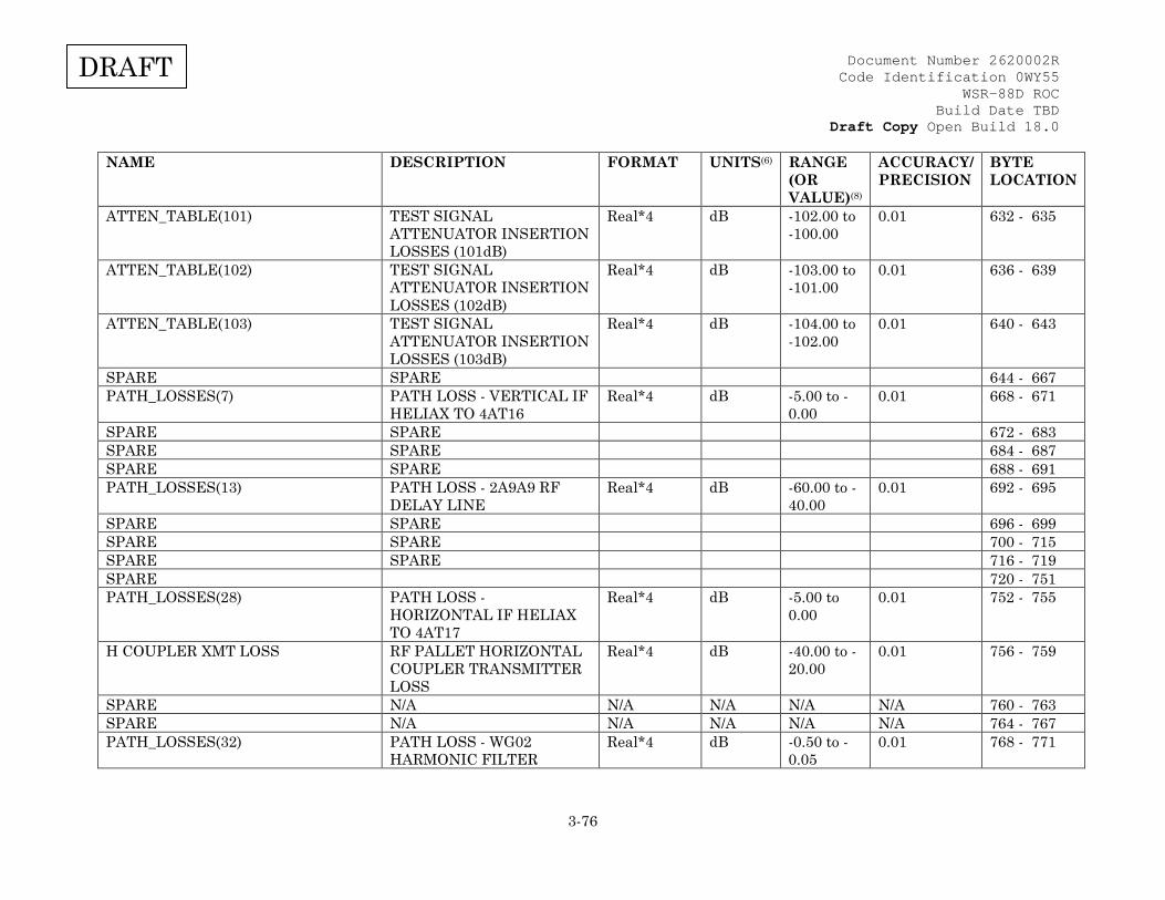
Document Number 2620002R Code Identification 0WY55
WSR-88D ROC Build Date TBD
Draft Copy Open Build 18.0
3-76
DRAFT
NAME DESCRIPTION FORMAT UNITS(6) RANGE (OR VALUE)(8)
ACCURACY/ PRECISION
BYTE LOCATION
ATTEN_TABLE(101) TEST SIGNAL ATTENUATOR INSERTION LOSSES (101dB)
Real*4 dB -102.00 to -100.00
0.01 632 - 635
ATTEN_TABLE(102) TEST SIGNAL ATTENUATOR INSERTION LOSSES (102dB)
Real*4 dB -103.00 to -101.00
0.01 636 - 639
ATTEN_TABLE(103) TEST SIGNAL ATTENUATOR INSERTION LOSSES (103dB)
Real*4 dB -104.00 to -102.00
0.01 640 - 643
SPARE SPARE 644 - 667 PATH_LOSSES(7) PATH LOSS - VERTICAL IF
HELIAX TO 4AT16 Real*4 dB -5.00 to -
0.00 0.01 668 - 671
SPARE SPARE 672 - 683 SPARE SPARE 684 - 687 SPARE SPARE 688 - 691 PATH_LOSSES(13) PATH LOSS - 2A9A9 RF
DELAY LINE Real*4 dB -60.00 to -
40.00 0.01 692 - 695
SPARE SPARE 696 - 699 SPARE SPARE 700 - 715 SPARE SPARE 716 - 719 SPARE 720 - 751 PATH_LOSSES(28) PATH LOSS -
HORIZONTAL IF HELIAX TO 4AT17
Real*4 dB -5.00 to 0.00
0.01 752 - 755
H COUPLER XMT LOSS RF PALLET HORIZONTAL COUPLER TRANSMITTER LOSS
Real*4 dB -40.00 to -20.00
0.01 756 - 759
SPARE N/A N/A N/A N/A N/A 760 - 763 SPARE N/A N/A N/A N/A N/A 764 - 767 PATH_LOSSES(32) PATH LOSS - WG02
HARMONIC FILTER Real*4 dB -0.50 to -
0.05 0.01 768 - 771
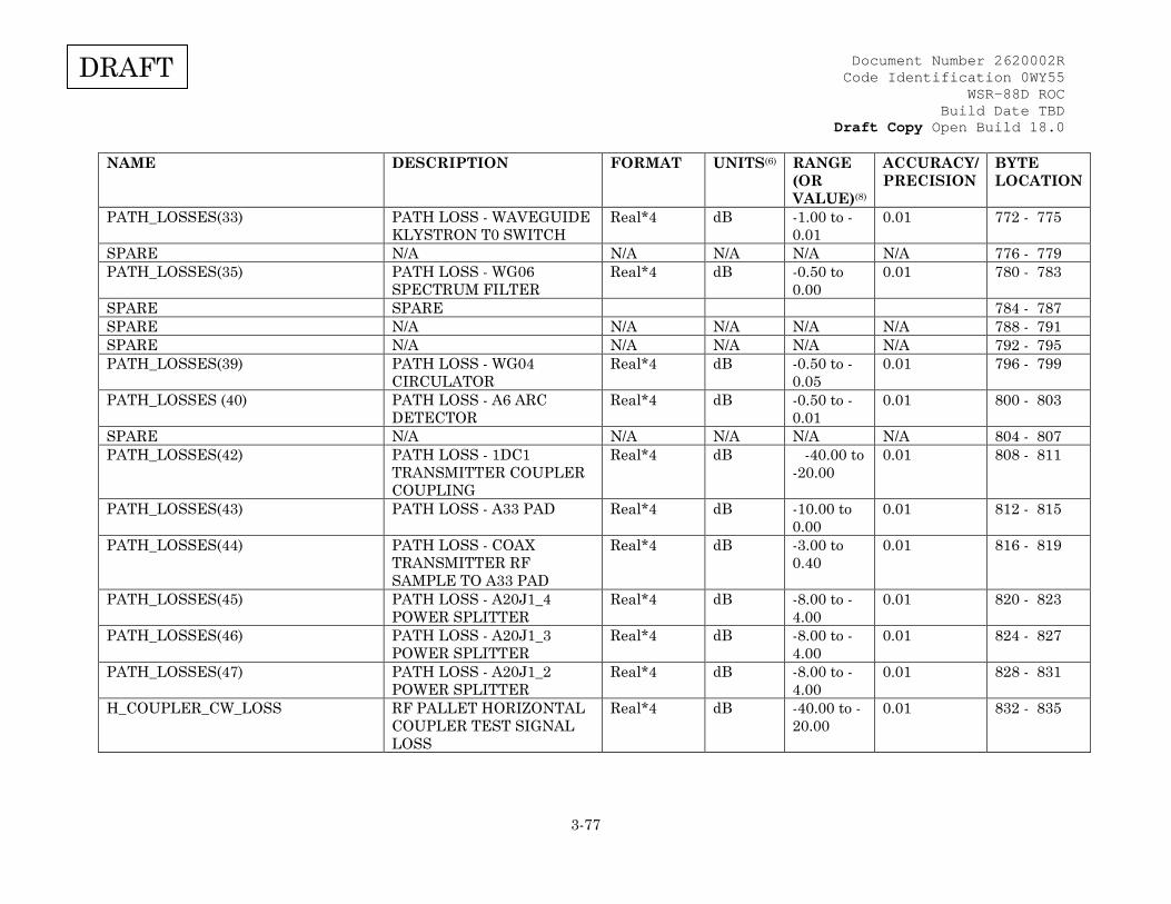
Document Number 2620002R Code Identification 0WY55
WSR-88D ROC Build Date TBD
Draft Copy Open Build 18.0
3-77
DRAFT
NAME DESCRIPTION FORMAT UNITS(6) RANGE (OR VALUE)(8)
ACCURACY/ PRECISION
BYTE LOCATION
PATH_LOSSES(33) PATH LOSS - WAVEGUIDE KLYSTRON T0 SWITCH
Real*4 dB -1.00 to -0.01
0.01 772 - 775
SPARE N/A N/A N/A N/A N/A 776 - 779 PATH_LOSSES(35) PATH LOSS - WG06
SPECTRUM FILTER Real*4 dB -0.50 to
0.00 0.01 780 - 783
SPARE SPARE 784 - 787 SPARE N/A N/A N/A N/A N/A 788 - 791 SPARE N/A N/A N/A N/A N/A 792 - 795 PATH_LOSSES(39) PATH LOSS - WG04
CIRCULATOR Real*4 dB -0.50 to -
0.05 0.01 796 - 799
PATH_LOSSES (40) PATH LOSS - A6 ARC DETECTOR
Real*4 dB -0.50 to -0.01
0.01 800 - 803
SPARE N/A N/A N/A N/A N/A 804 - 807 PATH_LOSSES(42) PATH LOSS - 1DC1
TRANSMITTER COUPLER COUPLING
Real*4 dB -40.00 to -20.00
0.01 808 - 811
PATH_LOSSES(43) PATH LOSS - A33 PAD Real*4 dB -10.00 to 0.00
0.01 812 - 815
PATH_LOSSES(44) PATH LOSS - COAX TRANSMITTER RF SAMPLE TO A33 PAD
Real*4 dB -3.00 to 0.40
0.01 816 - 819
PATH_LOSSES(45) PATH LOSS - A20J1_4 POWER SPLITTER
Real*4 dB -8.00 to -4.00
0.01 820 - 823
PATH_LOSSES(46) PATH LOSS - A20J1_3 POWER SPLITTER
Real*4 dB -8.00 to -4.00
0.01 824 - 827
PATH_LOSSES(47) PATH LOSS - A20J1_2 POWER SPLITTER
Real*4 dB -8.00 to -4.00
0.01 828 - 831
H_COUPLER_CW_LOSS RF PALLET HORIZONTAL COUPLER TEST SIGNAL LOSS
Real*4 dB -40.00 to -20.00
0.01 832 - 835
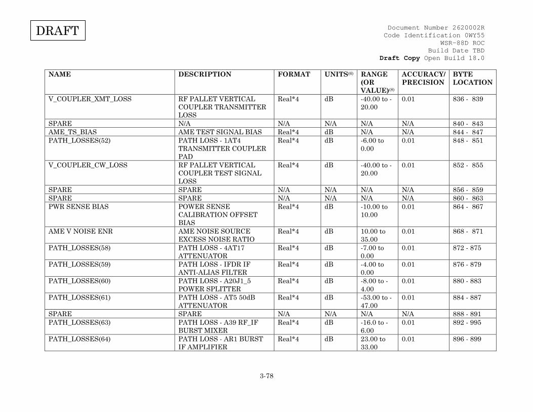
Document Number 2620002R Code Identification 0WY55
WSR-88D ROC Build Date TBD
Draft Copy Open Build 18.0
3-78
DRAFT
NAME DESCRIPTION FORMAT UNITS(6) RANGE (OR VALUE)(8)
ACCURACY/ PRECISION
BYTE LOCATION
V_COUPLER_XMT_LOSS RF PALLET VERTICAL COUPLER TRANSMITTER LOSS
Real*4 dB -40.00 to -20.00
0.01 836 - 839
SPARE N/A N/A N/A N/A N/A 840 - 843 AME_TS_BIAS AME TEST SIGNAL BIAS Real*4 dB N/A N/A 844 - 847 PATH_LOSSES(52) PATH LOSS - 1AT4
TRANSMITTER COUPLER PAD
Real*4 dB -6.00 to 0.00
0.01 848 - 851
V_COUPLER_CW_LOSS RF PALLET VERTICAL COUPLER TEST SIGNAL LOSS
Real*4 dB -40.00 to -20.00
0.01 852 - 855
SPARE SPARE N/A N/A N/A N/A 856 - 859 SPARE SPARE N/A N/A N/A N/A 860 - 863 PWR SENSE BIAS POWER SENSE
CALIBRATION OFFSET BIAS
Real*4 dB -10.00 to 10.00
0.01 864 - 867
AME V NOISE ENR AME NOISE SOURCE EXCESS NOISE RATIO
Real*4 dB 10.00 to 35.00
0.01 868 - 871
PATH_LOSSES(58) PATH LOSS - 4AT17 ATTENUATOR
Real*4 dB -7.00 to 0.00
0.01 872 - 875
PATH_LOSSES(59) PATH LOSS - IFDR IF ANTI-ALIAS FILTER
Real*4 dB -4.00 to 0.00
0.01 876 - 879
PATH_LOSSES(60) PATH LOSS - A20J1_5 POWER SPLITTER
Real*4 dB -8.00 to -4.00
0.01 880 - 883
PATH_LOSSES(61) PATH LOSS - AT5 50dB ATTENUATOR
Real*4 dB -53.00 to -47.00
0.01 884 - 887
SPARE SPARE N/A N/A N/A N/A 888 - 891 PATH_LOSSES(63) PATH LOSS - A39 RF_IF
BURST MIXER Real*4 dB -16.0 to -
6.00 0.01 892 - 995
PATH_LOSSES(64) PATH LOSS - AR1 BURST IF AMPLIFIER
Real*4 dB 23.00 to 33.00
0.01 896 - 899
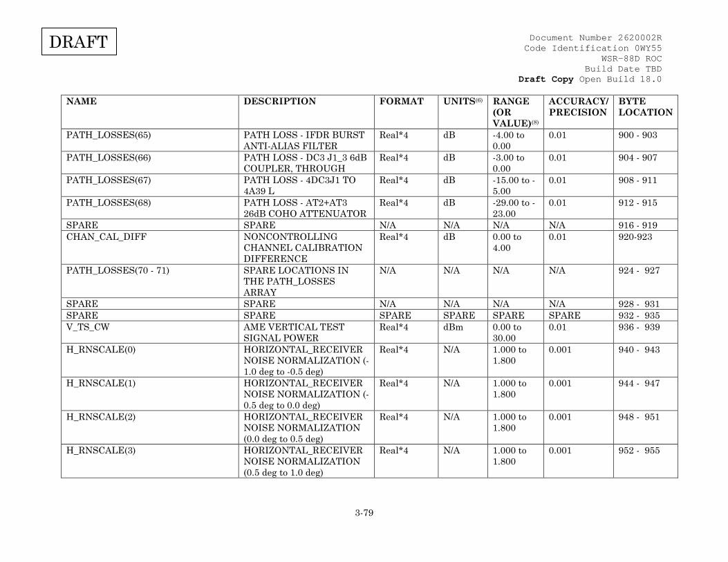
Document Number 2620002R Code Identification 0WY55
WSR-88D ROC Build Date TBD
Draft Copy Open Build 18.0
3-79
DRAFT
NAME DESCRIPTION FORMAT UNITS(6) RANGE (OR VALUE)(8)
ACCURACY/ PRECISION
BYTE LOCATION
PATH_LOSSES(65) PATH LOSS - IFDR BURST ANTI-ALIAS FILTER
Real*4 dB -4.00 to 0.00
0.01 900 - 903
PATH_LOSSES(66) PATH LOSS - DC3 J1_3 6dB COUPLER, THROUGH
Real*4 dB -3.00 to 0.00
0.01 904 - 907
PATH_LOSSES(67) PATH LOSS - 4DC3J1 TO 4A39 L
Real*4 dB -15.00 to -5.00
0.01 908 - 911
PATH_LOSSES(68) PATH LOSS - AT2+AT3 26dB COHO ATTENUATOR
Real*4 dB -29.00 to -23.00
0.01 912 - 915
SPARE SPARE N/A N/A N/A N/A 916 - 919 CHAN_CAL_DIFF NONCONTROLLING
CHANNEL CALIBRATION DIFFERENCE
Real*4 dB 0.00 to 4.00
0.01 920-923
PATH_LOSSES(70 - 71) SPARE LOCATIONS IN THE PATH_LOSSES ARRAY
N/A N/A N/A N/A 924 - 927
SPARE SPARE N/A N/A N/A N/A 928 - 931 SPARE SPARE SPARE SPARE SPARE SPARE 932 - 935 V_TS_CW AME VERTICAL TEST
SIGNAL POWER Real*4 dBm 0.00 to
30.00 0.01 936 - 939
H_RNSCALE(0) HORIZONTAL_RECEIVER NOISE NORMALIZATION (-1.0 deg to -0.5 deg)
Real*4 N/A 1.000 to 1.800
0.001 940 - 943
H_RNSCALE(1) HORIZONTAL_RECEIVER NOISE NORMALIZATION (-0.5 deg to 0.0 deg)
Real*4 N/A 1.000 to 1.800
0.001 944 - 947
H_RNSCALE(2) HORIZONTAL_RECEIVER NOISE NORMALIZATION (0.0 deg to 0.5 deg)
Real*4 N/A 1.000 to 1.800
0.001 948 - 951
H_RNSCALE(3) HORIZONTAL_RECEIVER NOISE NORMALIZATION (0.5 deg to 1.0 deg)
Real*4 N/A 1.000 to 1.800
0.001 952 - 955
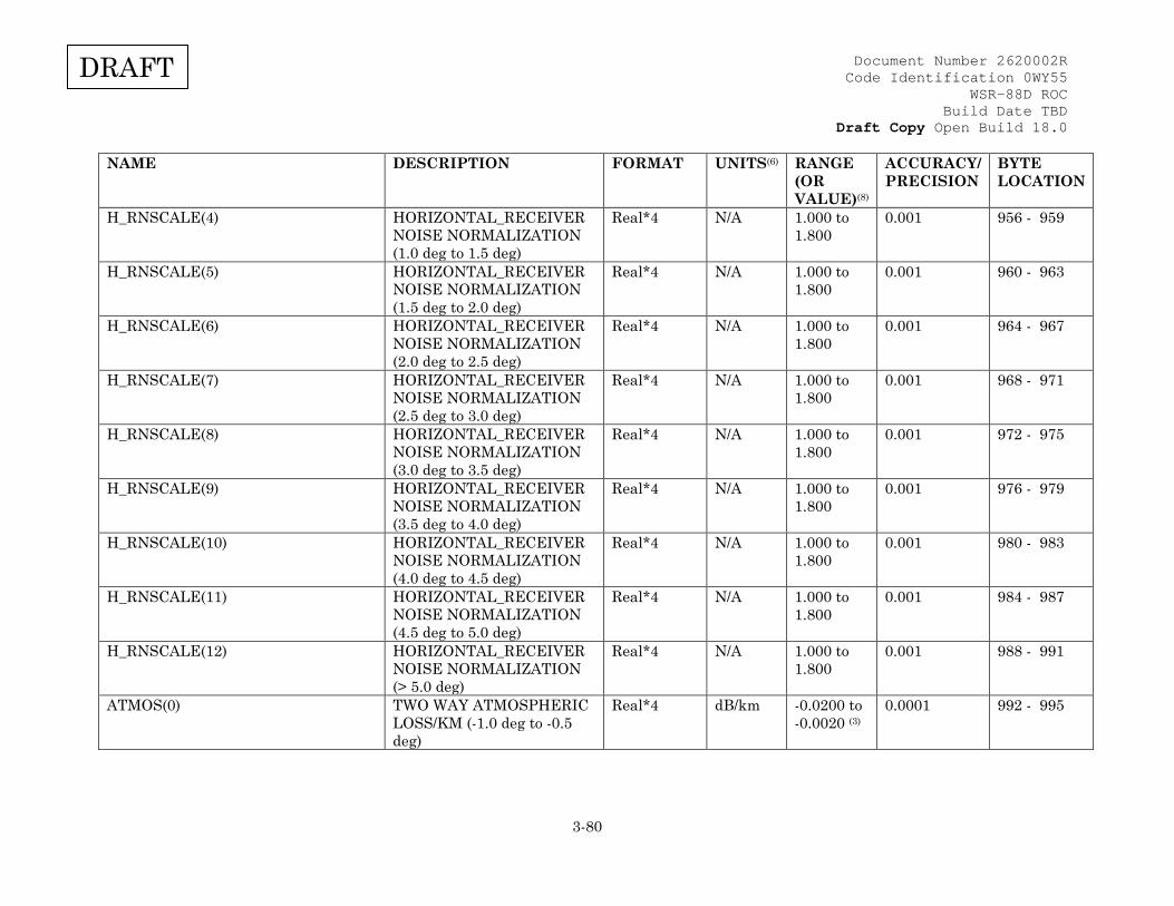
Document Number 2620002R Code Identification 0WY55
WSR-88D ROC Build Date TBD
Draft Copy Open Build 18.0
3-80
DRAFT
NAME DESCRIPTION FORMAT UNITS(6) RANGE (OR VALUE)(8)
ACCURACY/ PRECISION
BYTE LOCATION
H_RNSCALE(4) HORIZONTAL_RECEIVER NOISE NORMALIZATION (1.0 deg to 1.5 deg)
Real*4 N/A 1.000 to 1.800
0.001 956 - 959
H_RNSCALE(5) HORIZONTAL_RECEIVER NOISE NORMALIZATION (1.5 deg to 2.0 deg)
Real*4 N/A 1.000 to 1.800
0.001 960 - 963
H_RNSCALE(6) HORIZONTAL_RECEIVER NOISE NORMALIZATION (2.0 deg to 2.5 deg)
Real*4 N/A 1.000 to 1.800
0.001 964 - 967
H_RNSCALE(7) HORIZONTAL_RECEIVER NOISE NORMALIZATION (2.5 deg to 3.0 deg)
Real*4 N/A 1.000 to 1.800
0.001 968 - 971
H_RNSCALE(8) HORIZONTAL_RECEIVER NOISE NORMALIZATION (3.0 deg to 3.5 deg)
Real*4 N/A 1.000 to 1.800
0.001 972 - 975
H_RNSCALE(9) HORIZONTAL_RECEIVER NOISE NORMALIZATION (3.5 deg to 4.0 deg)
Real*4 N/A
1.000 to 1.800
0.001 976 - 979
H_RNSCALE(10) HORIZONTAL_RECEIVER NOISE NORMALIZATION (4.0 deg to 4.5 deg)
Real*4 N/A
1.000 to 1.800
0.001 980 - 983
H_RNSCALE(11) HORIZONTAL_RECEIVER NOISE NORMALIZATION (4.5 deg to 5.0 deg)
Real*4 N/A
1.000 to 1.800
0.001 984 - 987
H_RNSCALE(12) HORIZONTAL_RECEIVER NOISE NORMALIZATION (> 5.0 deg)
Real*4 N/A
1.000 to 1.800
0.001 988 - 991
ATMOS(0) TWO WAY ATMOSPHERIC LOSS/KM (-1.0 deg to -0.5 deg)
Real*4 dB/km -0.0200 to -0.0020 (3)
0.0001 992 - 995

Document Number 2620002R Code Identification 0WY55
WSR-88D ROC Build Date TBD
Draft Copy Open Build 18.0
3-81
DRAFT
NAME DESCRIPTION FORMAT UNITS(6) RANGE (OR VALUE)(8)
ACCURACY/ PRECISION
BYTE LOCATION
ATMOS(1) TWO WAY ATMOSPHERIC LOSS/KM (-0.5 deg to 0.0 deg)
Real*4 dB/km -0.0200 to -0.0020 (3)
0.0001 996 - 999
ATMOS(2) TWO WAY ATMOSPHERIC LOSS/KM (0.0 deg to 0.5 deg)
Real*4 dB/km -0.0200 to -0.0020 (3)
0.0001 1000 - 1003
ATMOS(3) TWO WAY ATMOSPHERIC LOSS/KM (0.5 deg to 1.0 deg)
Real*4 dB/km -0.0200 to -0.0020 (3)
0.0001 1004 - 1007
ATMOS(4) TWO WAY ATMOSPHERIC LOSS/KM (1.0 deg to 1.5 deg)
Real*4 dB/km -0.0200 to -0.0020 (3)
0.0001 1008 - 1011
ATMOS(5) TWO WAY ATMOSPHERIC LOSS/KM (1.5 deg to 2.0 deg)
Real*4 dB/km -0.0200 to -0.0020 (3)
0.0001 1012 - 1015
ATMOS(6) TWO WAY ATMOSPHERIC LOSS/KM (2.0 deg to 2.5 deg)
Real*4 dB/km -0.0200 to -0.0020 (3)
0.0001 1016 - 1019
ATMOS(7) TWO WAY ATMOSPHERIC LOSS/KM (2.5 deg to 3.0 deg)
Real*4 dB/km -0.0200 to -0.0020 (3)
0.0001 1020 - 1023
ATMOS(8) TWO WAY ATMOSPHERIC LOSS/KM (3.0 deg to 3.5 deg)
Real*4 dB/km -0.0200 to -0.0020 (3)
0.0001 1024 - 1027
ATMOS(9) TWO WAY ATMOSPHERIC LOSS/KM (3.5 deg to 4.0 deg)
Real*4 dB/km -0.0200 to -0.0020 (3)
0.0001 1028 - 1031
ATMOS(10) TWO WAY ATMOSPHERIC LOSS/KM (4.0 deg to 4.5 deg)
Real*4 dB/km -0.0200 to -0.0020 (3)
0.0001 1032 - 1035
ATMOS(11) TWO WAY ATMOSPHERIC LOSS/KM (4.5 deg to 5.0 deg)
Real*4 dB/km -0.0200 to -0.0020 (3)
0.0001 1036 - 1039
ATMOS(12) TWO WAY ATMOSPHERIC LOSS/KM (> 5.0 deg)
Real*4 dB/km -0.0200 to -0.0020 (3)
0.0001 1040 - 1043
EL_INDEX(0) BYPASS MAP GENERATION ELEVATION ANGLE (0)
Real*4 deg -1.000 to 45.000
0.001 1044 - 1047
EL_INDEX(1) BYPASS MAP GENERATION ELEVATION ANGLE (1)
Real*4 deg -1.000 to 45.000
0.001 1048 - 1051
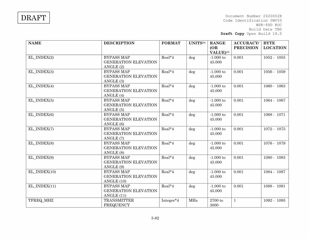
Document Number 2620002R Code Identification 0WY55
WSR-88D ROC Build Date TBD
Draft Copy Open Build 18.0
3-82
DRAFT
NAME DESCRIPTION FORMAT UNITS(6) RANGE (OR VALUE)(8)
ACCURACY/ PRECISION
BYTE LOCATION
EL_INDEX(2) BYPASS MAP GENERATION ELEVATION ANGLE (2)
Real*4 deg -1.000 to 45.000
0.001 1052 - 1055
EL_INDEX(3) BYPASS MAP GENERATION ELEVATION ANGLE (3)
Real*4 deg -1.000 to 45.000
0.001 1056 - 1059
EL_INDEX(4) BYPASS MAP GENERATION ELEVATION ANGLE (4)
Real*4 deg -1.000 to 45.000
0.001 1060 - 1063
EL_INDEX(5) BYPASS MAP GENERATION ELEVATION ANGLE (5)
Real*4 deg -1.000 to 45.000
0.001 1064 - 1067
EL_INDEX(6) BYPASS MAP GENERATION ELEVATION ANGLE (6)
Real*4 deg -1.000 to 45.000
0.001 1068 - 1071
EL_INDEX(7) BYPASS MAP GENERATION ELEVATION ANGLE (7)
Real*4 deg -1.000 to 45.000
0.001 1072 - 1075
EL_INDEX(8) BYPASS MAP GENERATION ELEVATION ANGLE (8)
Real*4 deg -1.000 to 45.000
0.001 1076 - 1079
EL_INDEX(9) BYPASS MAP GENERATION ELEVATION ANGLE (9)
Real*4 deg -1.000 to 45.000
0.001 1080 - 1083
EL_INDEX(10) BYPASS MAP GENERATION ELEVATION ANGLE (10)
Real*4 deg -1.000 to 45.000
0.001 1084 - 1087
EL_INDEX(11) BYPASS MAP GENERATION ELEVATION ANGLE (11)
Real*4 deg -1.000 to 45.000
0.001 1088 - 1091
TFREQ_MHZ TRANSMITTER FREQUENCY
Integer*4 MHz 2700 to 3000
1 1092 - 1095
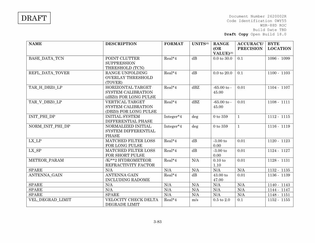
Document Number 2620002R Code Identification 0WY55
WSR-88D ROC Build Date TBD
Draft Copy Open Build 18.0
3-83
DRAFT
NAME DESCRIPTION FORMAT UNITS(6) RANGE (OR VALUE)(8)
ACCURACY/ PRECISION
BYTE LOCATION
BASE_DATA_TCN POINT CLUTTER SUPPRESSION THRESHOLD (TCN)
Real*4 dB 0.0 to 30.0 0.1 1096 - 1099
REFL_DATA_TOVER RANGE UNFOLDING OVERLAY THRESHOLD (TOVER)
Real*4 dB 0.0 to 20.0 0.1 1100 - 1103
TAR_H_DBZ0_LP HORIZONTAL TARGET SYSTEM CALIBRATION (dBZ0) FOR LONG PULSE
Real*4 dBZ -65.00 to -45.00
0.01 1104 - 1107
TAR_V_DBZ0_LP VERTICAL TARGET SYSTEM CALIBRATION (DBZ0) FOR LONG PULSE
Real*4 dBZ -65.00 to -45.00
0.01 1108 - 1111
INIT_PHI_DP INITIAL SYSTEM DIFFERENTIAL PHASE
Integer*4 deg 0 to 359 1 1112 - 1115
NORM_INIT_PHI_DP NORMALIZED INITIAL SYSTEM DIFFERENTIAL PHASE
Integer*4 deg 0 to 359 1 1116 - 1119
LX_LP MATCHED FILTER LOSS FOR LONG PULSE
Real*4 dB -3.00 to 0.00
0.01 1120 - 1123
LX_SP MATCHED FILTER LOSS FOR SHORT PULSE
Real*4 dB -3.00 to 0.00
0.01 1124 - 1127
METEOR_PARAM /K/**2 HYDROMETEOR REFRACTIVITY FACTOR
Real*4 N/A 0.10 to 1.10
0.01 1128 - 1131
SPARE N/A N/A N/A N/A N/A 1132 - 1135 ANTENNA_GAIN ANTENNA GAIN
INCLUDING RADOME Real*4 dB 43.00 to
47.00 0.01 1136 - 1139
SPARE N/A N/A N/A N/A N/A 1140 - 1143 SPARE N/A N/A N/A N/A N/A 1144 - 1147 SPARE SPARE N/A N/A N/A N/A 1148 - 1151 VEL_DEGRAD_LIMIT VELOCITY CHECK DELTA
DEGRADE LIMIT Real*4 m/s 0.5 to 2.0 0.1 1152 - 1155
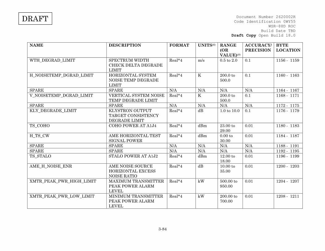
Document Number 2620002R Code Identification 0WY55
WSR-88D ROC Build Date TBD
Draft Copy Open Build 18.0
3-84
DRAFT
NAME DESCRIPTION FORMAT UNITS(6) RANGE (OR VALUE)(8)
ACCURACY/ PRECISION
BYTE LOCATION
WTH_DEGRAD_LIMIT SPECTRUM WIDTH CHECK DELTA DEGRADE LIMIT
Real*4 m/s 0.5 to 2.0 0.1 1156 - 1159
H_NOISETEMP_DGRAD_LIMIT HORIZONTAL SYSTEM NOISE TEMP DEGRADE LIMIT
Real*4 K 200.0 to 500.0
0.1 1160 - 1163
SPARE SPARE N/A N/A N/A N/A 1164 - 1167 V_NOISETEMP_DGRAD_LIMIT VERTICAL SYSTEM NOISE
TEMP DEGRADE LIMIT Real*4 K 200.0 to
500.0 0.1 1168 - 1171
SPARE SPARE N/A N/A N/A N/A 1172 - 1175 KLY_DEGRADE_LIMIT KLYSTRON OUTPUT
TARGET CONSISTENCY DEGRADE LIMIT
Real*4 dB 1.0 to 10.0 0.1 1176 - 1179
TS_COHO COHO POWER AT A1J4 Real*4 dBm 23.00 to 29.00
0.01 1180 - 1183
H_TS_CW AME HORIZONTAL TEST SIGNAL POWER
Real*4 dBm 0.00 to 30.00
0.01 1184 - 1187
SPARE SPARE N/A N/A N/A N/A 1188 - 1191 SPARE SPARE N/A N/A N/A N/A 1192 - 1195 TS_STALO STALO POWER AT A1J2 Real*4 dBm 12.00 to
18.00 0.01 1196 - 1199
AME_H_NOISE_ENR AME NOISE SOURCE HORIZONTAL EXCESS NOISE RATIO
Real*4 dB 10.00 to 35.00
0.01 1200 - 1203
XMTR_PEAK_PWR_HIGH_LIMIT MAXIMUM TRANSMITTER PEAK POWER ALARM LEVEL
Real*4 kW 500.00 to 950.00
0.01 1204 - 1207
XMTR_PEAK_PWR_LOW_LIMIT MINIMUM TRANSMITTER PEAK POWER ALARM LEVEL
Real*4 kW 200.00 to 700.00
0.01 1208 - 1211
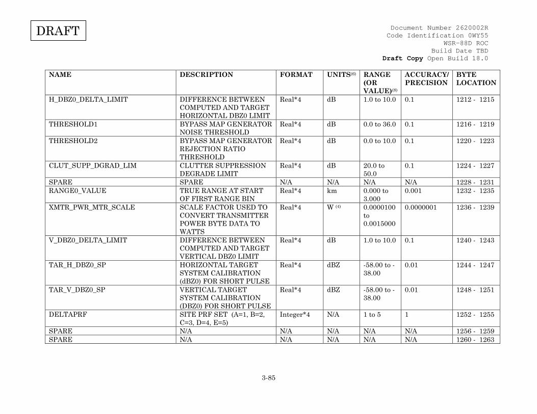
Document Number 2620002R Code Identification 0WY55
WSR-88D ROC Build Date TBD
Draft Copy Open Build 18.0
3-85
DRAFT
NAME DESCRIPTION FORMAT UNITS(6) RANGE (OR VALUE)(8)
ACCURACY/ PRECISION
BYTE LOCATION
H_DBZ0_DELTA_LIMIT DIFFERENCE BETWEEN COMPUTED AND TARGET HORIZONTAL DBZ0 LIMIT
Real*4 dB 1.0 to 10.0 0.1 1212 - 1215
THRESHOLD1 BYPASS MAP GENERATOR NOISE THRESHOLD
Real*4 dB 0.0 to 36.0 0.1 1216 - 1219
THRESHOLD2 BYPASS MAP GENERATOR REJECTION RATIO THRESHOLD
Real*4 dB 0.0 to 10.0 0.1 1220 - 1223
CLUT_SUPP_DGRAD_LIM CLUTTER SUPPRESSION DEGRADE LIMIT
Real*4 dB 20.0 to 50.0
0.1 1224 - 1227
SPARE SPARE N/A N/A N/A N/A 1228 - 1231 RANGE0_VALUE TRUE RANGE AT START
OF FIRST RANGE BIN Real*4 km 0.000 to
3.000 0.001 1232 - 1235
XMTR_PWR_MTR_SCALE SCALE FACTOR USED TO CONVERT TRANSMITTER POWER BYTE DATA TO WATTS
Real*4 W (4) 0.0000100 to 0.0015000
0.0000001 1236 - 1239
V_DBZ0_DELTA_LIMIT DIFFERENCE BETWEEN COMPUTED AND TARGET VERTICAL DBZ0 LIMIT
Real*4 dB 1.0 to 10.0 0.1 1240 - 1243
TAR_H_DBZ0_SP HORIZONTAL TARGET SYSTEM CALIBRATION (dBZ0) FOR SHORT PULSE
Real*4 dBZ -58.00 to -38.00
0.01 1244 - 1247
TAR_V_DBZ0_SP VERTICAL TARGET SYSTEM CALIBRATION (DBZ0) FOR SHORT PULSE
Real*4 dBZ -58.00 to -38.00
0.01 1248 - 1251
DELTAPRF SITE PRF SET (A=1, B=2, C=3, D=4, E=5)
Integer*4 N/A 1 to 5 1 1252 - 1255
SPARE N/A N/A N/A N/A N/A 1256 - 1259 SPARE N/A N/A N/A N/A N/A 1260 - 1263
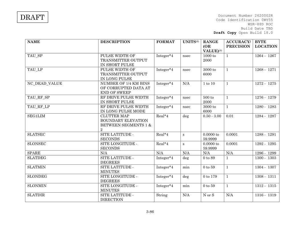
Document Number 2620002R Code Identification 0WY55
WSR-88D ROC Build Date TBD
Draft Copy Open Build 18.0
3-86
DRAFT
NAME DESCRIPTION FORMAT UNITS(6) RANGE (OR VALUE)(8)
ACCURACY/ PRECISION
BYTE LOCATION
TAU_SP PULSE WIDTH OF TRANSMITTER OUTPUT IN SHORT PULSE
Integer*4 nsec 1000 to 2000
1 1264 - 1267
TAU_LP PULSE WIDTH OF TRANSMITTER OUTPUT IN LONG PULSE
Integer*4 nsec 3000 to 6000
1 1268 - 1271
NC_DEAD_VALUE NUMBER OF 1/4 KM BINS OF CORRUPTED DATA AT END OF SWEEP
Integer*4 N/A 1 to 10 1 1272 - 1275
TAU_RF_SP RF DRIVE PULSE WIDTH IN SHORT PULSE
Integer*4 nsec 500 to 2000
1 1276 - 1279
TAU_RF_LP RF DRIVE PULSE WIDTH IN LONG PULSE MODE
Integer*4 nsec 3000 to 6000
1 1280 - 1283
SEG1LIM CLUTTER MAP BOUNDARY ELEVATION BETWEEN SEGMENTS 1 & 2
Real*4 deg 0.50 - 3.00 0.01 1284 - 1287
SLATSEC SITE LATITUDE - SECONDS
Real*4 s 0.0000 to 59.9999
0.0001 1288 - 1291
SLONSEC SITE LONGITUDE - SECONDS
Real*4 s 0.0000 to 59.9999
0.0001 1292 - 1295
SPARE N/A N/A N/A N/A N/A 1296 - 1299 SLATDEG SITE LATITUDE -
DEGREES Integer*4 deg 0 to 89 1 1300 - 1303
SLATMIN SITE LATITUDE - MINUTES
Integer*4 min 0 to 59 1 1304 - 1307
SLONDEG SITE LONGITUDE - DEGREES
Integer*4 deg 0 to 179 1 1308 - 1311
SLONMIN SITE LONGITUDE - MINUTES
Integer*4 min 0 to 59 1 1312 - 1315
SLATDIR SITE LATITUDE - DIRECTION
String N/A N or S N/A 1316 - 1319
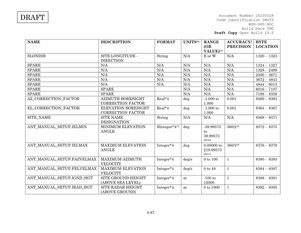
Document Number 2620002R Code Identification 0WY55
WSR-88D ROC Build Date TBD
Draft Copy Open Build 18.0
3-87
DRAFT
NAME DESCRIPTION FORMAT UNITS(6) RANGE (OR VALUE)(8)
ACCURACY/ PRECISION
BYTE LOCATION
SLONDIR SITE LONGITUDE - DIRECTION
String N/A E or W N/A 1320 - 1323
SPARE N/A N/A N/A N/A N/A 1324 - 1327 SPARE N/A N/A N/A N/A N/A 1328 - 2499 SPARE N/A N/A N/A N/A N/A 2500 - 3671 SPARE N/A N/A N/A N/A N/A 3672 - 4843 SPARE N/A N/A N/A N/A N/A 4844 - 6015 SPARE SPARE N/A N/A N/A 6016 - 7187 SPARE SPARE N/A N/A N/A 7188 - 8359 AZ_CORRECTION_FACTOR AZIMUTH BORESIGHT
CORRECTION FACTOR Real*4 deg -1.000 to
1.000 0.001 8360 - 8363
EL_CORRECTION_FACTOR ELEVATION BORESIGHT CORRECTION FACTOR
Real*4 deg -1.000 to 1.000
0.001 8364 - 8367
SITE_NAME SITE NAME DESIGNATION
String N/A
N/A
N/A 8368 - 8371
ANT_MANUAL_SETUP.IELMIN MINIMUM ELEVATION ANGLE
SInteger*4(7) deg -39.99573 to 39.99573 (9)(10)
360/216 8372 - 8375
ANT_MANUAL_SETUP.IELMAX MAXIMUM ELEVATION ANGLE
Integer*4 deg 0.00000 to 219.99573 (9)(11)
360/216 8376 - 8379
ANT_MANUAL_SETUP.FAZVELMAX MAXIMUM AZIMUTH VELOCITY
Integer*4 deg/s 0 to 100 1 8380 - 8383
ANT_MANUAL_SETUP.FELVELMAX MAXIMUM ELEVATION VELOCITY
Integer*4 deg/s 0 to 48 1 8384 - 8387
ANT_MANUAL_SETUP.IGND_HGT SITE GROUND HEIGHT (ABOVE SEA LEVEL)
Integer*4 m -100 to 12000
1 8388 - 8391
ANT_MANUAL_SETUP.IRAD_HGT SITE RADAR HEIGHT (ABOVE GROUND)
Integer*4 m 0 to 1000 1 8392 - 8395
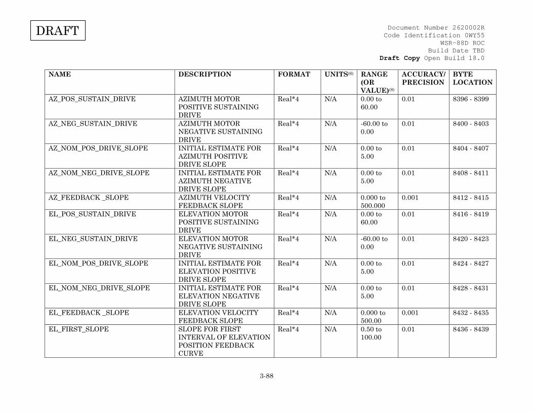
Document Number 2620002R Code Identification 0WY55
WSR-88D ROC Build Date TBD
Draft Copy Open Build 18.0
3-88
DRAFT
NAME DESCRIPTION FORMAT UNITS(6) RANGE (OR VALUE)(8)
ACCURACY/ PRECISION
BYTE LOCATION
AZ_POS_SUSTAIN_DRIVE AZIMUTH MOTOR POSITIVE SUSTAINING DRIVE
Real*4 N/A 0.00 to 60.00
0.01 8396 - 8399
AZ_NEG_SUSTAIN_DRIVE AZIMUTH MOTOR NEGATIVE SUSTAINING DRIVE
Real*4 N/A -60.00 to 0.00
0.01 8400 - 8403
AZ_NOM_POS_DRIVE_SLOPE INITIAL ESTIMATE FOR AZIMUTH POSITIVE DRIVE SLOPE
Real*4 N/A 0.00 to 5.00
0.01 8404 - 8407
AZ_NOM_NEG_DRIVE_SLOPE INITIAL ESTIMATE FOR AZIMUTH NEGATIVE DRIVE SLOPE
Real*4 N/A 0.00 to 5.00
0.01 8408 - 8411
AZ_FEEDBACK _SLOPE AZIMUTH VELOCITY FEEDBACK SLOPE
Real*4 N/A 0.000 to 500.000
0.001 8412 - 8415
EL_POS_SUSTAIN_DRIVE ELEVATION MOTOR POSITIVE SUSTAINING DRIVE
Real*4 N/A 0.00 to 60.00
0.01 8416 - 8419
EL_NEG_SUSTAIN_DRIVE ELEVATION MOTOR NEGATIVE SUSTAINING DRIVE
Real*4 N/A -60.00 to 0.00
0.01 8420 - 8423
EL_NOM_POS_DRIVE_SLOPE INITIAL ESTIMATE FOR ELEVATION POSITIVE DRIVE SLOPE
Real*4 N/A 0.00 to 5.00
0.01 8424 - 8427
EL_NOM_NEG_DRIVE_SLOPE INITIAL ESTIMATE FOR ELEVATION NEGATIVE DRIVE SLOPE
Real*4 N/A 0.00 to 5.00
0.01 8428 - 8431
EL_FEEDBACK _SLOPE ELEVATION VELOCITY FEEDBACK SLOPE
Real*4 N/A 0.000 to 500.00
0.001 8432 - 8435
EL_FIRST_SLOPE SLOPE FOR FIRST INTERVAL OF ELEVATION POSITION FEEDBACK CURVE
Real*4 N/A 0.50 to 100.00
0.01 8436 - 8439

Document Number 2620002R Code Identification 0WY55
WSR-88D ROC Build Date TBD
Draft Copy Open Build 18.0
3-89
DRAFT
NAME DESCRIPTION FORMAT UNITS(6) RANGE (OR VALUE)(8)
ACCURACY/ PRECISION
BYTE LOCATION
EL_SECOND_SLOPE SLOPE FOR SECOND INTERVAL OF ELEVATION POSITION FEEDBACK CURVE
Real*4 N/A 0.10 to 100.00
0.01 8440 - 8443
EL_THIRD_SLOPE SLOPE FOR THIRD INTERVAL OF ELEVATION POSITION FEEDBACK CURVE
Real*4 N/A 0.00 to 100.00
0.01 8444 - 8447
EL_DROOP_POS NEUTRAL DROOP ANGLE Real*4 deg -180.00 to 180.00
0.01 8448 - 8451
EL_OFF_NEUTRAL_DRIVE 90 DEGREE OFF NEUTRAL DRIVE
Real*4 N/A -100.00 to 100.00
0.01 8452 - 8455
SPARE N/A N/A N/A N/A N/A 8456 - 8695 RVP8NV.IWAVEGUIDE_LENGTH WAVEGUIDE LENGTH Integer*4 m 0 to 1000 1 8696 - 8699 V_RNSCALE(0) RECEIVER NOISE
NORMALIZATION (-1.0 deg to -0.5 deg)
Real*4 N/A 1.000 to 1.800
0.001 8700 - 8703
V_RNSCALE(1) VERTICAL RECEIVER NOISE NORMALIZATION (-0.5 deg to 0.0 deg)
Real*4 N/A 1.000 to 1.800
0.001 8704 - 8707
V_RNSCALE(2) VERTICAL RECEIVER NOISE NORMALIZATION (0.0 deg to 0.5 deg)
Real*4 N/A 1.000 to 1.800
0.001 8708 - 8711
V_RNSCALE(3) VERTICAL RECEIVER NOISE NORMALIZATION (0.5 deg to 1.0 deg)
Real*4 N/A 1.000 to 1.800
0.001 8712 - 8715
V_RNSCALE(4) VERTICAL RECEIVER NOISE NORMALIZATION (1.0 deg to 1.5 deg)
Real*4 N/A 1.000 to 1.800
0.001 8716 - 8719
V_RNSCALE(5) VERTICAL RECEIVER NOISE NORMALIZATION (1.5 deg to 2.0 deg)
Real*4 N/A 1.000 to 1.800
0.001 8720 - 8723

Document Number 2620002R Code Identification 0WY55
WSR-88D ROC Build Date TBD
Draft Copy Open Build 18.0
3-90
DRAFT
NAME DESCRIPTION FORMAT UNITS(6) RANGE (OR VALUE)(8)
ACCURACY/ PRECISION
BYTE LOCATION
V_RNSCALE(6) VERTICAL RECEIVER NOISE NORMALIZATION (2.0 deg to 2.5 deg)
Real*4 N/A 1.000 to 1.800
0.001 8724 - 8727
V_RNSCALE(7) VERTICAL RECEIVER NOISE NORMALIZATION (2.5 deg to 3.0 deg)
Real*4 N/A 1.000 to 1.800
0.001 8728 - 8731
V_RNSCALE(8) VERTICAL RECEIVER NOISE NORMALIZATION (3.0 deg to 3.5 deg)
Real*4 N/A 1.000 to 1.800
0.001 8732 - 8735
V_RNSCALE(9) VERTICAL RECEIVER NOISE NORMALIZATION (3.5 deg to 4.0 deg)
Real*4 N/A 1.000 to 1.800
0.001 8736 - 8739
V_RNSCALE(10) VERTICAL RECEIVER NOISE NORMALIZATION (4.0 deg to 4.5 deg)
Real*4 N/A 1.000 to 1.800
0.001 8740 - 8743
VEL_DATA_TOVER VELOCITY UNFOLDING OVERLAY THRESHOLD
Real*4 dB 0.0 to 20.0 0.1 8744 - 8747
WIDTH_DATA_TOVER WIDTH UNFOLDING OVERLAY THRESHOLD
Real*4 dB 0.0 to 20.0 0.1 8748 - 8751
V_RNSCALE(11) VERTICAL RECEIVER NOISE NORMALIZATION (4.5 deg to 5.0 deg)
Real*4 N/A 1.000 to 1.800
0.001 8752 - 8755
V_RNSCALE(12) VERTICAL RECEIVER NOISE NORMALIZATION (>5.0 deg)
Real*4 N/A 1.000 to 1.800
0.001 8756 - 8759
SPARE N/A N/A N/A N/A N/A 8760 - 8763 DOPPLER_RANGE_START START RANGE FOR FIRST
DOPPLER RADIAL Real*4 km -32.768 to
32.768 0.001 8764 - 8767
MAX_EL_INDEX THE MAXIMUM INDEX FOR THE EL_INDEX PARAMETERS
Integer*4 N/A 0 to 11 1 8768 - 8771

Document Number 2620002R Code Identification 0WY55
WSR-88D ROC Build Date TBD
Draft Copy Open Build 18.0
3-91
DRAFT
NAME DESCRIPTION FORMAT UNITS(6) RANGE (OR VALUE)(8)
ACCURACY/ PRECISION
BYTE LOCATION
SEG2LIM CLUTTER MAP BOUNDARY ELEVATION BETWEEN SEGMENTS 2 & 3.
Real*4 deg 0.80 - 4.50 0.01 8772 - 8775
SEG3LIM CLUTTER MAP BOUNDARY ELEVATION BETWEEN SEGMENTS 3 & 4.
Real*4 deg 1.00 - 6.00 0.01 8776 - 8779
SEG4LIM CLUTTER MAP BOUNDARY ELEVATION BETWEEN SEGMENTS 4 & 5.
Real*4 deg 1.00 - 8.00 0.01 8780 - 8783
NBR_EL_SEGMENTS NUMBER OF ELEVATION SEGMENTS IN ORDA CLUTTER MAP.
Integer*4 N/A 1 - 5 1 8784 - 8787
H_NOISE_LONG
HORIZONTAL RECEIVER NOISE FOR LONG PULSE
Real*4 dBm -95.0 to -80.0
0.1 8788 - 8791
ANT_NOISE_TEMP
ANTENNA NOISE TEMPERATURE
Real*4 K 30.0 to 200.0
0.1 8792 - 8795
H_NOISE_SHORT HORIZONTAL RECEIVER NOISE FOR SHORT PULSE
Real*4 dBm -90.0 to -75.0
0.1 8796 - 8799
H_NOISE_TOLERANCE HORIZONTAL RECEIVER NOISE TOLERANCE
Real*4 dB 0.0 to 6.0 0.1 8800 - 8803
MIN_H_DYN_RANGE MINIMUM HORIZONTAL DYNAMIC RANGE
Real*4 dB 85.0 to 95.0
0.1 8804 - 8807
GEN_INSTALLED AUXILIARY GENERATOR INSTALLED (FAA ONLY)
String N/A T or F N/A 8808 - 8811
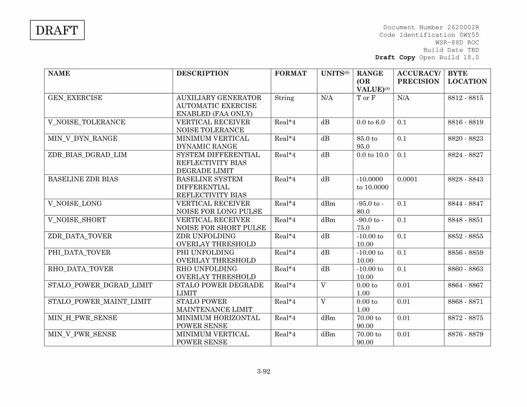
Document Number 2620002R Code Identification 0WY55
WSR-88D ROC Build Date TBD
Draft Copy Open Build 18.0
3-92
DRAFT
NAME DESCRIPTION FORMAT UNITS(6) RANGE (OR VALUE)(8)
ACCURACY/ PRECISION
BYTE LOCATION
GEN_EXERCISE AUXILIARY GENERATOR AUTOMATIC EXERCISE ENABLED (FAA ONLY)
String N/A T or F N/A 8812 - 8815
V_NOISE_TOLERANCE VERTICAL RECEIVER NOISE TOLERANCE
Real*4 dB 0.0 to 6.0 0.1 8816 - 8819
MIN_V_DYN_RANGE MINIMUM VERTICAL DYNAMIC RANGE
Real*4 dB 85.0 to 95.0
0.1 8820 - 8823
ZDR_BIAS_DGRAD_LIM SYSTEM DIFFERENTIAL REFLECTIVITY BIAS DEGRADE LIMIT
Real*4 dB 0.0 to 10.0 0.1 8824 - 8827
BASELINE ZDR BIAS BASELINE SYSTEM DIFFERENTIAL REFLECTIVITY BIAS
Real*4 dB -10.0000 to 10.0000
0.0001 8828 - 8843
V_NOISE_LONG VERTICAL RECEIVER NOISE FOR LONG PULSE
Real*4 dBm -95.0 to -80.0
0.1 8844 - 8847
V_NOISE_SHORT VERTICAL RECEIVER NOISE FOR SHORT PULSE
Real*4 dBm -90.0 to -75.0
0.1 8848 - 8851
ZDR_DATA_TOVER ZDR UNFOLDING OVERLAY THRESHOLD
Real*4 dB -10.00 to 10.00
0.1 8852 - 8855
PHI_DATA_TOVER PHI UNFOLDING OVERLAY THRESHOLD
Real*4 dB -10.00 to 10.00
0.1 8856 - 8859
RHO_DATA_TOVER RHO UNFOLDING OVERLAY THRESHOLD
Real*4 dB -10.00 to 10.00
0.1 8860 - 8863
STALO_POWER_DGRAD_LIMIT STALO POWER DEGRADE LIMIT
Real*4 V 0.00 to 1.00
0.01 8864 - 8867
STALO_POWER_MAINT_LIMIT STALO POWER MAINTENANCE LIMIT
Real*4 V 0.00 to 1.00
0.01 8868 - 8871
MIN_H_PWR_SENSE MINIMUM HORIZONTAL POWER SENSE
Real*4 dBm 70.00 to 90.00
0.01 8872 - 8875
MIN_V_PWR_SENSE MINIMUM VERTICAL POWER SENSE
Real*4 dBm 70.00 to 90.00
0.01 8876 - 8879

Document Number 2620002R Code Identification 0WY55
WSR-88D ROC Build Date TBD
Draft Copy Open Build 18.0
3-93
DRAFT
NAME DESCRIPTION FORMAT UNITS(6) RANGE (OR VALUE)(8)
ACCURACY/ PRECISION
BYTE LOCATION
H_PWR_SENSE_OFFSET HORIZONTAL POWER SENSE CALIBRATION OFFSET
Real*4 dB -100.00 to -50.00
0.01 8880 - 8883
V_PWR_SENSE_OFFSET VERTICAL POWER SENSE CALIBRATION OFFSET
Real*4 dB -100.00 to -50.00
0.01 8884 - 8887
PS_GAIN_REF POWER SENSE GAIN REFERENCE VALUE
Real*4 dB -40.00 to -20.00
0.01 8888 - 8891
RF_PALLET_BROAD_LOSS RF PALLET BROADBAND LOSS
Real*4 dB -10.00 to 0.00
0.01 8892 - 8895
ZDR_CHECK_THRESHOLD ZDR CHECK FAILURE THRESHOLD
Real*4 dB 0.00 to 10.00
0.01 8896 - 8899
PHI_CHECK_THRESHOLD PHI CHECK FAILURE THRESHOLD
Real*4 deg 0.00 to 20.00
0.01 8900 - 8903
RHO_CHECK_THRESHOLD RHO CHECK FAILURE THRESHOLD
Real*4 ratio 0.00 to 1.00
0.01 8904 - 8907
SPARE SPARE 8908 - 8959 AME_PS_TOLERANCE AME POWER SUPPLY
TOLERANCE Real*4 % 0.0 to 20.0 0.1 8960 - 8963
AME_MAX_TEMP MAXIMUM AME INTERNAL ALARM TEMPERATURE
Real*4 deg C 0.0 to 65.0 0.1 8964 - 8967
AME_MIN_TEMP MINIMUM AME INTERNAL ALARM TEMPERATURE
Real*4 deg C -10.0 to 20.0
0.1 8968 - 8971
RCVR_MOD_MAX_TEMP MAXIMUM AME RECEIVER MODULE ALARM TEMPERATURE
Real*4 deg C 0.0 to 65.0 0.1 8972 - 8975
RCVR_MOD_MIN_TEMP MINIMUM AME RECEIVER MODULE ALARM TEMPERATURE
Real*4 deg C -10.0 to 20.0
0.1 8976 - 8979
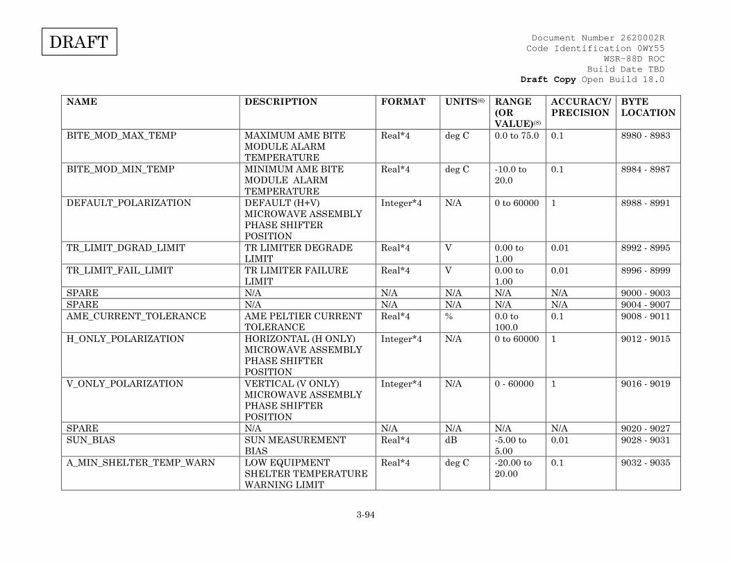
Document Number 2620002R Code Identification 0WY55
WSR-88D ROC Build Date TBD
Draft Copy Open Build 18.0
3-94
DRAFT
NAME DESCRIPTION FORMAT UNITS(6) RANGE (OR VALUE)(8)
ACCURACY/ PRECISION
BYTE LOCATION
BITE_MOD_MAX_TEMP MAXIMUM AME BITE MODULE ALARM TEMPERATURE
Real*4 deg C 0.0 to 75.0 0.1 8980 - 8983
BITE_MOD_MIN_TEMP MINIMUM AME BITE MODULE ALARM TEMPERATURE
Real*4 deg C -10.0 to 20.0
0.1 8984 - 8987
DEFAULT_POLARIZATION DEFAULT (H+V) MICROWAVE ASSEMBLY PHASE SHIFTER POSITION
Integer*4 N/A 0 to 60000 1 8988 - 8991
TR_LIMIT_DGRAD_LIMIT TR LIMITER DEGRADE LIMIT
Real*4 V 0.00 to 1.00
0.01 8992 - 8995
TR_LIMIT_FAIL_LIMIT TR LIMITER FAILURE LIMIT
Real*4 V 0.00 to 1.00
0.01 8996 - 8999
SPARE N/A N/A N/A N/A N/A 9000 - 9003 SPARE N/A N/A N/A N/A N/A 9004 - 9007 AME_CURRENT_TOLERANCE AME PELTIER CURRENT
TOLERANCE Real*4 % 0.0 to
100.0 0.1 9008 - 9011
H_ONLY_POLARIZATION HORIZONTAL (H ONLY) MICROWAVE ASSEMBLY PHASE SHIFTER POSITION
Integer*4 N/A 0 to 60000 1 9012 - 9015
V_ONLY_POLARIZATION VERTICAL (V ONLY) MICROWAVE ASSEMBLY PHASE SHIFTER POSITION
Integer*4 N/A 0 - 60000 1 9016 - 9019
SPARE N/A N/A N/A N/A N/A 9020 - 9027 SUN_BIAS SUN MEASUREMENT
BIAS Real*4 dB -5.00 to
5.00 0.01 9028 - 9031
A_MIN_SHELTER_TEMP_WARN LOW EQUIPMENT SHELTER TEMPERATURE WARNING LIMIT
Real*4 deg C -20.00 to 20.00
0.1 9032 - 9035

Document Number 2620002R Code Identification 0WY55
WSR-88D ROC Build Date TBD
Draft Copy Open Build 18.0
3-95
DRAFT
NAME DESCRIPTION FORMAT UNITS(6) RANGE (OR VALUE)(8)
ACCURACY/ PRECISION
BYTE LOCATION
POWER_METER_ZERO POWER METER 0 BIAS VOLTAGE
Real*4 v -10.00 to 10.00
.01 9036 - 9039
TXB_BASELINE Expected value of the RDA transmit bias (TXB) between the horizontal and vertical channels
Real*4 dB -1.000 to 1.000
0.001 9040 - 9043
TXB_ALARM_THRESH Threshold for delta between an actual measurement of TXB, and the expected TXB BASELINE value for the RDA to set an alarm
Real*4 dB 0 to 1.000 0.001 9044 - 9047
SPARE N/A N/A N/A N/A N/A 9048 - 9467 Notes: 1. Format is "mm/dd/yy", where mm = month, dd = day, and yy = year. 2. Format is "hh-mm-ss", where hh = hour, mm = minutes, and ss = seconds. 3. See Table XVI for default value. 4. Value of the LSB of the power measurement. 5. N/A. 6. See Appendix B for unit definitions and standard symbology. 7. Two's complement integer value should be multiplied by 360/216 to get the actual value in degrees. 8. Range shown is after applicable scaling and conversion has been applied. 9. Precision is shown to 5 decimal places. Actual precision is 13 digits. 10. Integer range is -7281 to 7281. 11. Integer range is 0 to 40049. 12. Format is "baseline" or "current". 13. Format is "11", null terminated string. This is always "11", for all builds. 14. Format is "10", null terminated string. This number is the build number and changes with each build. 15. "T" or "F", null terminated string.
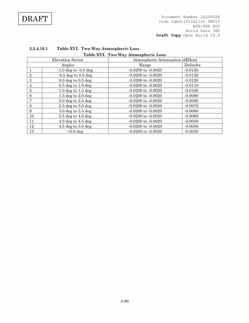
Document Number 2620002R Code Identification 0WY55
WSR-88D ROC Build Date TBD
Draft Copy Open Build 18.0
3-96
DRAFT
3.2.4.16.1 Table XVI. Two Way Atmospheric Loss Table XVI. Two Way Atmospheric Loss
Elevation Sector Atmospheric Attenuation (dB/km) Angles Range Defaults
1 -1.0 deg to -0.5 deg -0.0200 to -0.0020 -0.0150 2 -0.5 deg to 0.0 deg -0.0200 to -0.0020 -0.0150 3 0.0 deg to 0.5 deg -0.0200 to -0.0020 -0.0120 4 0.5 deg to 1.0 deg -0.0200 to -0.0020 -0.0110 5 1.0 deg to 1.5 deg -0.0200 to -0.0020 -0.0100 6 1.5 deg to 2.0 deg -0.0200 to -0.0020 -0.0090 7 2.0 deg to 2.5 deg -0.0200 to -0.0020 -0.0080 8 2.5 deg to 3.0 deg -0.0200 to -0.0020 -0.0070 9 3.0 deg to 3.5 deg -0.0200 to -0.0020 -0.0060 10 3.5 deg to 4.0 deg -0.0200 to -0.0020 -0.0060 11 4.0 deg to 4.5 deg -0.0200 to -0.0020 -0.0050 12 4.5 deg to 5.0 deg -0.0200 to -0.0020 -0.0050 13 >5.0 deg -0.0200 to -0.0020 -0.0050

Document Number 2620002R Code Identification 0WY55
WSR-88D ROC Build Date TBD
Draft Copy Open Build 18.0
3-97
DRAFT
3.2.4.17 Table XVII. Digital Radar Data Generic Format Blocks (Message Type 31) Table XVII. Digital Radar Data Generic Format Blocks (Message Type 31)
3.2.4.17.1 Table XVII-A. Data Header Block Table XVII-A. Data Header Block
NAME DESCRIPTION FORMAT UNITS (1)
RANGE (2) ACCURACY/ PRECISION
BYTE LOCATION(3)
Radar Identifier ICAO Radar Identifier String N/A (e.g., "KTLX") N/A 0 to 3 Collection Time Radial data collection time in
milliseconds past midnight GMT Integer*4 msec 0 to 86,399,999 ± 2000/
1 4 to 7
Modified Julian Date
Current Julian date - 2440586.5 (4) Integer*2 d 1 to 65,535 1 8 and 9
Azimuth Number
Radial number within elevation scan Integer*2 N/A 1 to 720 1 10 and 11
Azimuth Angle Azimuth angle at which radial data was collected
Real*4 deg 0 to 359.956055 ± 0.1°/ NA
12 to 15
Compression Indicator
Indicates if message type 31 is compressed and what method of compression is used. The Data Header Block is not compressed.
Code*1 N/A 0 = uncompressed 1 = compressed using BZIP2 2 = compressed using zlib 3 = future use
N/A 16
Spare Spare and forces halfword alignment N/A N/A N/A N/A 17 Radial Length Uncompressed length of the radial in
bytes including the Data Header block length
Integer*2 N/A 9352 to 14288 bytes 1 18 and 19
Azimuth Resolution Spacing
Azimuthal spacing between adjacent radials
Code*1 N/A 1 = 0.5° (5)
2 = 1.0° N/A 20
Radial Status Radial Status (e.g. first, last)
Code*1 N/A 0 to 132 (6) N/A 21
Elevation Number
Elevation number within volume scan Integer*1 N/A 1 to 25 1 22
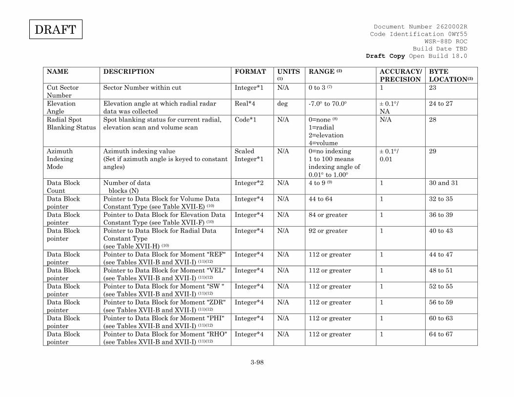
Document Number 2620002R Code Identification 0WY55
WSR-88D ROC Build Date TBD
Draft Copy Open Build 18.0
3-98
DRAFT
NAME DESCRIPTION FORMAT UNITS (1)
RANGE (2) ACCURACY/ PRECISION
BYTE LOCATION(3)
Cut Sector Number
Sector Number within cut Integer*1 N/A 0 to 3 (7) 1 23
Elevation Angle
Elevation angle at which radial radar data was collected
Real*4 deg -7.0° to 70.0° ± 0.1°/ NA
24 to 27
Radial Spot Blanking Status
Spot blanking status for current radial, elevation scan and volume scan
Code*1 N/A 0=none (8)
1=radial 2=elevation 4=volume
N/A 28
Azimuth Indexing Mode
Azimuth indexing value (Set if azimuth angle is keyed to constant angles)
Scaled Integer*1
N/A 0=no indexing 1 to 100 means indexing angle of 0.01° to 1.00°
± 0.1°/ 0.01
29
Data Block Count
Number of data blocks (N)
Integer*2 N/A 4 to 9 (9) 1 30 and 31
Data Block pointer
Pointer to Data Block for Volume Data Constant Type (see Table XVII-E) (10)
Integer*4 N/A 44 to 64 1 32 to 35
Data Block pointer
Pointer to Data Block for Elevation Data Constant Type (see Table XVII-F) (10)
Integer*4 N/A 84 or greater 1 36 to 39
Data Block pointer
Pointer to Data Block for Radial Data Constant Type (see Table XVII-H) (10)
Integer*4 N/A 92 or greater 1 40 to 43
Data Block pointer
Pointer to Data Block for Moment "REF" (see Tables XVII-B and XVII-I) (11)(12)
Integer*4 N/A 112 or greater 1 44 to 47
Data Block pointer
Pointer to Data Block for Moment "VEL" (see Tables XVII-B and XVII-I) (11)(12)
Integer*4 N/A 112 or greater 1 48 to 51
Data Block pointer
Pointer to Data Block for Moment "SW " (see Tables XVII-B and XVII-I) (11)(12)
Integer*4 N/A 112 or greater 1 52 to 55
Data Block pointer
Pointer to Data Block for Moment "ZDR" (see Tables XVII-B and XVII-I) (11)(12)
Integer*4 N/A 112 or greater 1 56 to 59
Data Block pointer
Pointer to Data Block for Moment "PHI" (see Tables XVII-B and XVII-I) (11)(12)
Integer*4 N/A 112 or greater 1 60 to 63
Data Block pointer
Pointer to Data Block for Moment "RHO" (see Tables XVII-B and XVII-I) (11)(12)
Integer*4 N/A 112 or greater 1 64 to 67
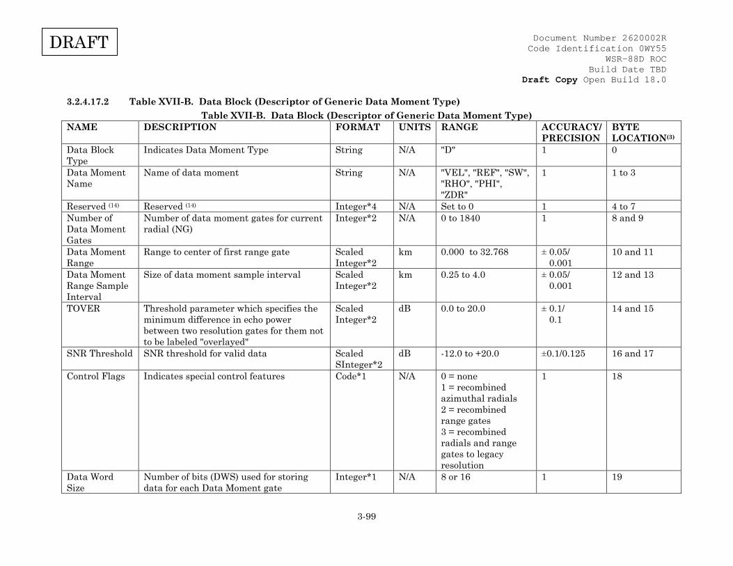
Document Number 2620002R Code Identification 0WY55
WSR-88D ROC Build Date TBD
Draft Copy Open Build 18.0
3-99
DRAFT
3.2.4.17.2 Table XVII-B. Data Block (Descriptor of Generic Data Moment Type) Table XVII-B. Data Block (Descriptor of Generic Data Moment Type)
NAME DESCRIPTION FORMAT UNITS RANGE ACCURACY/ PRECISION
BYTE LOCATION(3)
Data Block Type
Indicates Data Moment Type String N/A "D" 1 0
Data Moment Name
Name of data moment String N/A "VEL", "REF", "SW", "RHO", "PHI", "ZDR"
1 1 to 3
Reserved (14) Reserved (14) Integer*4 N/A Set to 0 1 4 to 7 Number of Data Moment Gates
Number of data moment gates for current radial (NG)
Integer*2 N/A 0 to 1840 1 8 and 9
Data Moment Range
Range to center of first range gate Scaled Integer*2
km 0.000 to 32.768 ± 0.05/ 0.001
10 and 11
Data Moment Range Sample Interval
Size of data moment sample interval Scaled Integer*2
km 0.25 to 4.0 ± 0.05/ 0.001
12 and 13
TOVER Threshold parameter which specifies the minimum difference in echo power between two resolution gates for them not to be labeled "overlayed"
Scaled Integer*2
dB 0.0 to 20.0 ± 0.1/ 0.1
14 and 15
SNR Threshold SNR threshold for valid data Scaled SInteger*2
dB -12.0 to +20.0 ±0.1/0.125 16 and 17
Control Flags Indicates special control features Code*1 N/A 0 = none 1 = recombined azimuthal radials 2 = recombined range gates 3 = recombined radials and range gates to legacy resolution
1 18
Data Word Size
Number of bits (DWS) used for storing data for each Data Moment gate
Integer*1 N/A 8 or 16 1 19
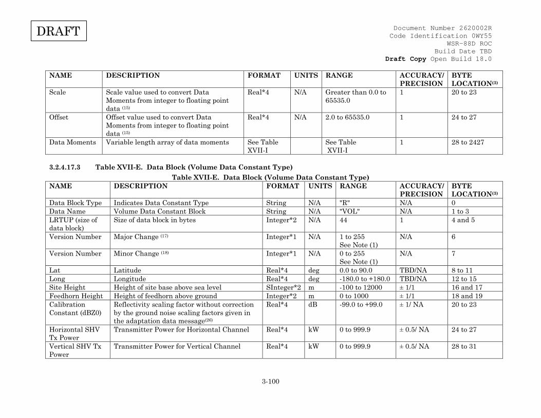
Document Number 2620002R Code Identification 0WY55
WSR-88D ROC Build Date TBD
Draft Copy Open Build 18.0
3-100
DRAFT
NAME DESCRIPTION FORMAT UNITS RANGE ACCURACY/ PRECISION
BYTE LOCATION(3)
Scale Scale value used to convert Data Moments from integer to floating point data (15)
Real*4 N/A Greater than 0.0 to 65535.0
1 20 to 23
Offset Offset value used to convert Data Moments from integer to floating point data (15)
Real*4 N/A 2.0 to 65535.0 1 24 to 27
Data Moments Variable length array of data moments See Table XVII-I
See Table XVII-I
1 28 to 2427
3.2.4.17.3 Table XVII-E. Data Block (Volume Data Constant Type) Table XVII-E. Data Block (Volume Data Constant Type)
NAME DESCRIPTION FORMAT UNITS RANGE ACCURACY/ PRECISION
BYTE LOCATION(3)
Data Block Type Indicates Data Constant Type String N/A "R" N/A 0 Data Name Volume Data Constant Block String N/A "VOL" N/A 1 to 3 LRTUP (size of data block)
Size of data block in bytes Integer*2 N/A 44
1 4 and 5
Version Number
Major Change (17) Integer*1 N/A 1 to 255 See Note (1)
N/A 6
Version Number Minor Change (18) Integer*1 N/A 0 to 255 See Note (1)
N/A 7
Lat Latitude Real*4 deg 0.0 to 90.0 TBD/NA 8 to 11 Long Longitude Real*4 deg -180.0 to +180.0 TBD/NA 12 to 15 Site Height Height of site base above sea level SInteger*2 m -100 to 12000 ± 1/1 16 and 17 Feedhorn Height Height of feedhorn above ground Integer*2 m 0 to 1000 ± 1/1 18 and 19 Calibration Constant (dBZ0)
Reflectivity scaling factor without correction by the ground noise scaling factors given in the adaptation data message(26)
Real*4 dB -99.0 to +99.0 ± 1/ NA 20 to 23
Horizontal SHV Tx Power
Transmitter Power for Horizontal Channel Real*4 kW 0 to 999.9 ± 0.5/ NA 24 to 27
Vertical SHV Tx Power
Transmitter Power for Vertical Channel Real*4 kW 0 to 999.9 ± 0.5/ NA 28 to 31
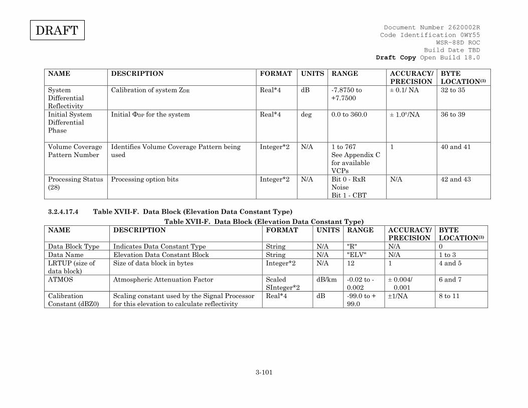
Document Number 2620002R Code Identification 0WY55
WSR-88D ROC Build Date TBD
Draft Copy Open Build 18.0
3-101
DRAFT
NAME DESCRIPTION FORMAT UNITS RANGE ACCURACY/ PRECISION
BYTE LOCATION(3)
System Differential Reflectivity
Calibration of system ZDR Real*4 dB -7.8750 to +7.7500
± 0.1/ NA 32 to 35
Initial System Differential Phase
Initial ΦDP for the system Real*4 deg 0.0 to 360.0 ± 1.0°/NA 36 to 39
Volume Coverage Pattern Number
Identifies Volume Coverage Pattern being used
Integer*2 N/A 1 to 767 See Appendix C for available VCPs
1 40 and 41
Processing Status (28)
Processing option bits Integer*2 N/A Bit 0 - RxR Noise Bit 1 - CBT
N/A 42 and 43
3.2.4.17.4 Table XVII-F. Data Block (Elevation Data Constant Type) Table XVII-F. Data Block (Elevation Data Constant Type)
NAME DESCRIPTION FORMAT UNITS RANGE ACCURACY/ PRECISION
BYTE LOCATION(3)
Data Block Type Indicates Data Constant Type String N/A "R" N/A 0 Data Name Elevation Data Constant Block String N/A "ELV" N/A 1 to 3 LRTUP (size of data block)
Size of data block in bytes Integer*2 N/A 12
1 4 and 5
ATMOS Atmospheric Attenuation Factor Scaled SInteger*2
dB/km -0.02 to -0.002
± 0.004/ 0.001
6 and 7
Calibration Constant (dBZ0)
Scaling constant used by the Signal Processor for this elevation to calculate reflectivity
Real*4 dB -99.0 to + 99.0
±1/NA 8 to 11
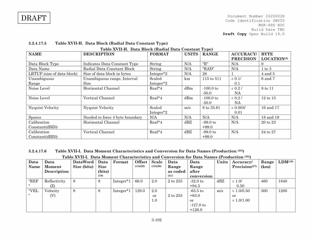
Document Number 2620002R Code Identification 0WY55
WSR-88D ROC Build Date TBD
Draft Copy Open Build 18.0
3-102
DRAFT
3.2.4.17.5 Table XVII-H. Data Block (Radial Data Constant Type) Table XVII-H. Data Block (Radial Data Constant Type)
NAME DESCRIPTION FORMAT UNITS RANGE ACCURACY/ PRECISION
BYTE LOCATION(3)
Data Block Type Indicates Data Constant Type String N/A "R" N/A 0 Data Name Radial Data Constant Block String N/A "RAD" N/A 1 to 3 LRTUP (size of data block) Size of data block in bytes Integer*2 N/A 28 1 4 and 5 Unambiguous Range
Unambiguous range, Interval Size
Scaled Integer*2
km 115 to 511 ± 0.1/ 0.1
6 and 7
Noise Level Horizontal Channel Real*4 dBm -100.0 to -50.0
± 0.2 / NA
8 to 11
Noise Level Vertical Channel Real*4 dBm -100.0 to -50.0
± 0.2 / NA
12 to 15
Nyquist Velocity Nyquist Velocity Scaled Integer*2
m/s 8 to 35.61
± 0.003/ 0.01
16 and 17
Spares Needed to force 4 byte boundary N/A N/A N/A N/A 18 and 19 Calibration Constant(dBZ0)
Horizontal Channel Real*4 dBZ -99.0 to +99.0
N/A 20 to 23
Calibration Constant(dBZ0)
Vertical Channel Real*4 dBZ -99.0 to +99.0
N/A 24 to 27
3.2.4.17.6 Table XVII-I. Data Moment Characteristics and Conversion for Data Names (Production (25)) Table XVII-I. Data Moment Characteristics and Conversion for Data Names (Production (25))
Data Name
Data Moment Description
DataWord Size (bits)
Data Size (bits) (19)
Format Offset (15)(20)
Scale (15)(20)
Data Range as coded (21)
Data Range after conversion
Units Accuracy/ Precision(27)
Range (km)
LDM(16)
"REF "
Reflectivity (Z)
8 8 Integer*1 66.0 2.0 2 to 255 -32.0 to +94.5
dBZ ± 1.0/ 0.50
460 1840
"VEL "
Velocity (V)
8 8 Integer*1 129.0 2.0 or 1.0
2 to 255
-63.5 to +63.0 or -127.0 to +126.0
m/s ± 1.0/0.50 or ± 1.0/1.00
300 1200
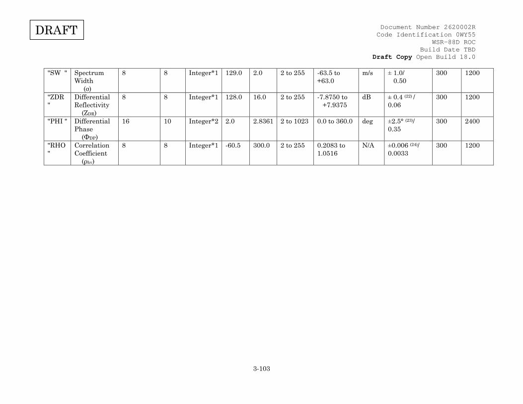
Document Number 2620002R Code Identification 0WY55
WSR-88D ROC Build Date TBD
Draft Copy Open Build 18.0
3-103
DRAFT
"SW " Spectrum Width (σ)
8 8 Integer*1 129.0 2.0 2 to 255 -63.5 to +63.0
m/s ± 1.0/ 0.50
300 1200
"ZDR "
Differential Reflectivity (ZDR)
8 8 Integer*1 128.0 16.0 2 to 255 -7.8750 to +7.9375
dB ± 0.4 (22) / 0.06
300 1200
"PHI " Differential Phase (ΦDP)
16 10 Integer*2 2.0 2.8361 2 to 1023 0.0 to 360.0 deg ±2.5° (23)/ 0.35
300 2400
"RHO "
Correlation Coefficient (ρhv)
8 8 Integer*1 -60.5 300.0 2 to 255 0.2083 to 1.0516
N/A ±0.006 (24)/ 0.0033
300 1200

Document Number 2620002R Code Identification 0WY55
WSR-88D ROC Build Date TBD
Draft Copy Open Build 18.0
3-104
DRAFT
3.2.4.17.7 Table XVII-K. Generic Format Header Block and Data Block (Message Type 31) (Notional description showing pointers)
Table XVII-K. Generic Format Header Block and Data Block (Message Type 31) (Notional description showing pointers)
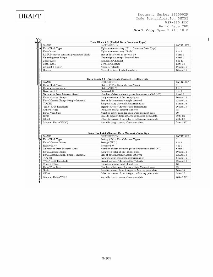
Document Number 2620002R Code Identification 0WY55
WSR-88D ROC Build Date TBD
Draft Copy Open Build 18.0
3-105
DRAFT

Document Number 2620002R Code Identification 0WY55
WSR-88D ROC Build Date TBD
Draft Copy Open Build 18.0
3-106
DRAFT

Document Number 2620002R Code Identification 0WY55
WSR-88D ROC Build Date TBD
Draft Copy Open Build 18.0
3-107
DRAFT
(1) See Appendix B for unit definitions and standard symbology. (2) This field represents the range of the item after any applicable scaling and conversion is done. (3) Byte location is relative to beginning of this message. (4) 1 January 1970 00.00 GMT = 1 Modified Julian Date. (5) Azimuthal spacing of radials is the commanded value not necessarily the actual spacing. (6) Format Defined in Table III-C. (Radial status definition) (7) A value of 0 is valid only for continuous surveillance cuts. (8) Equals 0 when spot blanking disabled; equals 4 when spot blanking enabled and no spot blanking radials in current elevation cut; equals 6 when there are no spot blanked radials in current elevation cut and current radial not spot blanked; equals 7 when current radial is spot blanked. (9) The number of data moments in each radial can vary from 1 to 6 depending on the VCP in use. There will always be 3 data blocks for "VOL", "ELV", and "RAD" plus the data moment block for "REF". Therefore, this parameter varies from 4 to 9. (10) Pointer is offset relative to beginning of Data Header Block (see table XVII-A). Note the Data Header Block for data blocks "VOL", "ELV", and "RAD" must always be present but the pointers are not order or location dependent but shown in this order in Table XVII-A for illustrative and clarity purposes. (11) Pointer is offset relative to beginning of Data Header Block (see table XVII-A) but if the pointer value is 0, there is no Data Moment Block referenced. Normally, if the Data Moment is missing, this pointer would not be present and the Data Block Count reduced. However, it is optional to set pointers to zero or simply delete the pointer to the missing Data Moment Block. (12) The presence of these Moment Pointers in each radial is determined by the VCP controlling the radar and can vary from none to 6 unique Moments. (13) Format Defined in Table III-B. (Range conversion) (14) "Reserved" means the field has a future use but not implemented at this time and must be set to zero. The field is not a "Spare" available for future use. (15) A non-zero Scale value indicates unsigned integer data that can be converted to floating point data using the Scale and Offset fields, i.e., F = (N - OFFSET) / SCALE where N is the integer data value and F is the resulting floating point value. A scale value of 0 indicates floating point moment data for each range gate. (16) LDM is the amount of space in bytes required for a data moment array and equals ((NG * DWS) / 8) where NG is the number of gates at the gate spacing resolution specified and DWS is the number of bits stored for each gate (DWS is always a multiple of 8). (17) Major version number. A larger major version number indicates a structural change has occurred within the ICD description. The current version is 2 for Build 14.
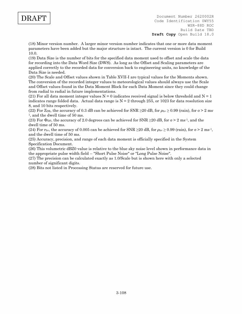
Document Number 2620002R Code Identification 0WY55
WSR-88D ROC Build Date TBD
Draft Copy Open Build 18.0
3-108
DRAFT
(18) Minor version number. A larger minor version number indicates that one or more data moment parameters have been added but the major structure is intact. The current version is 0 for Build 10.0. (19) Data Size is the number of bits for the specified data moment used to offset and scale the data for recording into the Data Word Size (DWS). As long as the Offset and Scaling parameters are applied correctly to the recorded data for conversion back to engineering units, no knowledge of the Data Size is needed. (20) The Scale and Offset values shown in Table XVII-I are typical values for the Moments shown. The conversion of the recorded integer values to meteorological values should always use the Scale and Offset values found in the Data Moment Block for each Data Moment since they could change from radial to radial in future implementations. (21) For all data moment integer values N = 0 indicates received signal is below threshold and N = 1 indicates range folded data. Actual data range is N = 2 through 255, or 1023 for data resolution size 8, and 10 bits respectively. (22) For ZDR, the accuracy of 0.3 dB can be achieved for SNR ≥20 dB, for ρhv ≥ 0.99 (rain), for σ > 2 ms-
1, and the dwell time of 50 ms. (23) For ΦDP, the accuracy of 2.0 degrees can be achieved for SNR ≥20 dB, for σ > 2 ms-1, and the dwell time of 50 ms. (24) For rhv, the accuracy of 0.005 can be achieved for SNR ≥20 dB, for ρhv ≥ 0.99 (rain), for σ > 2 ms-1, and the dwell time of 50 ms. (25) Accuracy, precision, and range of each data moment is officially specified in the System Specification Document. (26) This volumetric dBZ0 value is relative to the blue sky noise level shown in performance data in the appropriate pulse width field -- "Short Pulse Noise" or "Long Pulse Noise". (27) The precision can be calculated exactly as 1.0/Scale but is shown here with only a selected number of significant digits. (28) Bits not listed in Processing Status are reserved for future use.

Document Number 2620002R Code Identification 0WY55
WSR-88D ROC Build Date TBD
Draft Copy Open Build 18.0
3-109
DRAFT
3.2.4.18 Table XVIII. RDA PRF Data (Message Type 32) Table XVIII. RDA PRF Data (Message Type 32)
NAME DESCRIPTION FORMAT UNITS RANGE ACCURACY/ PRECISION
HALFWORD LOCATION
Number of Waveforms
The number of waveforms that PRF values are provided for
Integer*2 N/A 1 - 5 N/A 1
SPARE N/A Integer*2 N/A N/A N/A 2 First WAVEFORM TYPE
WAVEFORM TYPE of the first set of PRF DATA •Contiguous Serveillance •Contiguous Doppler w/Ambiguity Resolution •Staggered Pulse Pair
Code*2 N/A As listed(1)
•1 •2 •5
N/A P1(2)
PRF Count The number of PRFs following that are defined for this waveform type
Code*2 N/A 0 - 255 N/A P2
PRF 1 The PRF value for the first code of the waveform type
Scaled Integer*4
Hz 0 to 1500000
0.001 P3
PRF 2 Same as above, but for the second code
Scaled Integer*4
Hz 0 to 1500000
0.001 P5
PRF 3 Same as above, but for the third code
Scaled Integer*4
Hz 0 to 1500000
0.001 P7
PRF 4 Same as above, but for the fourth code
Scaled Integer*4
Hz 0 to 1500000
0.001 P9
PRF 5 Same as above, but for the fifth code
Scaled Integer*4
Hz 0 to 1500000
0.001 P11
PRF 6 Same as above, but for the sixth code
Scaled Integer*4
Hz 0 to 1500000
0.001 P13
PRF 7 Same as above, but for the seventh code
Scaled Integer*4
Hz 0 to 1500000
0.001 P15

Document Number 2620002R Code Identification 0WY55
WSR-88D ROC Build Date TBD
Draft Copy Open Build 18.0
3-110
DRAFT
NAME DESCRIPTION FORMAT UNITS RANGE ACCURACY/ PRECISION
HALFWORD LOCATION
PRF 8 Same as above, but for the eighth code
Scaled Integer*4
Hz 0 to 1500000
0.001 P17
...PRF N Same as above, but for the 'N'th PRF code
Scaled Integer*4
Hz 0 to 1500000
0.001 P'X'(3)
(1) For waveform type 3, the same PRFs as waveform type 2 will be used by the RDA. And for waveform type 4, the surveillance portion of Batch waveform uses the waveform type 1 PRFs, and the Doppler portion of the Batch waveform uses the codes from waveform type 2. (2) Repeat the format of P1 - P'X' (3), for each of the subsequent PRF data sections. (3) 'X' can be calculated as 3 + 2*(N-1) for the Nth PRF code of the waveform type.
3.2.5 Network Time Protocol (NTP)
3.2.5.1 LAN (RDA/RPG) Clock Synchronization Network Time Protocol (NTP) will be implemented for clock synchronization of the RPG and Master System Control Function (MSCF) processors. The RDA will serve as the master clock. The RPG A processor will serve as a secondary master clock in the event the RDA is unavailable. LAN components within the RPG and RDA (e.g. routers, LAN switches, etc.) will also use the RDA clock as the master and the RPG as a secondary. In FAA Redundant, the NTP master and secondary relationship is only specific to a given channel. Cross-channel secondary NTP sources are not implemented. For the frame relay hub routers serving DoD MSCFs, the local host NWS RDA and RPG are the primary and secondary time servers, respectively. For the frame relay hub routers service FAA MSCFs, the hub router will obtain time from only one of the FAA RDAs as primary and its respective RPG as secondary. The radar chosen for time service will correspond to the MSCF that is used to configure the frame relay hub router. Reference the TCP/IP ICD for design detail.
3.2.5.2 Applicable Standards The Network Time Protocol Standard RFC 1305 applies to the RDA/RPG LAN interface. If the master clock sends a time adjustment packet ± 1000 seconds, the client RPG processor(s) will reject the packet and manual intervention will be required to reset the client clocks within ± 1000 seconds of the RDA master clock. The exception is during the boot sequence of the client RPG processor(s). During the boot sequence, NTP will allow for a one-time setting of the client clock that is > 1000 seconds from its master clock. The initial clock set during RPG software loads should be set within ± 1000 seconds of the RDA clock.

Document Number 2620002R Code Identification 0WY55
WSR-88D ROC Build Date TBD
Draft Copy Open Build 18.0
A-1
DRAFT
APPENDIX A GLOSSARY TABLE Acronym / Abbreviation
Description
A Antenna/Pedestal A/D Analog/Digital AC Air conditioner AIS Alarm Indication Signal AMP Ampere ANSI American National Standards Institute ANT Antenna ARC/VSWR Arc/Voltage Standing Wave Ratio ARP Address Resolution Protocol ASCII American Standard Code for Information Interchange ATTEN Attenuator AVSET Automated Volume Scan Evaluation and Termination BDDS Base Data Distribution System BITE Built-in-Test-Equipment C Another designator for Communications CAL Calibration CF Clutter Filter CHAN Channel CI Configuration Item (hardware) CMD Command COHO Coherent COM Communications CPCI Computer Program Configuration Item CSU Channel Service Unit CTR Control CW Contiguous Wave DOC Department of Commerce DoD Department of Defense DOT Department of Transportation EBC Elevation Bias Correction ED Edge Detected EQUIP Equipment FAA Federal Aviation Administration FO Filtered Occurrence FREQ Frequency GEN Generator GPS Global Positioning System HCI Human Computer Interface I/O Input/Output ICD Interface Control Document ICMP Internet Control Message Protocol ID, I.D. Identification IHL Internet Header Length IN Inoperative INIT Initialization
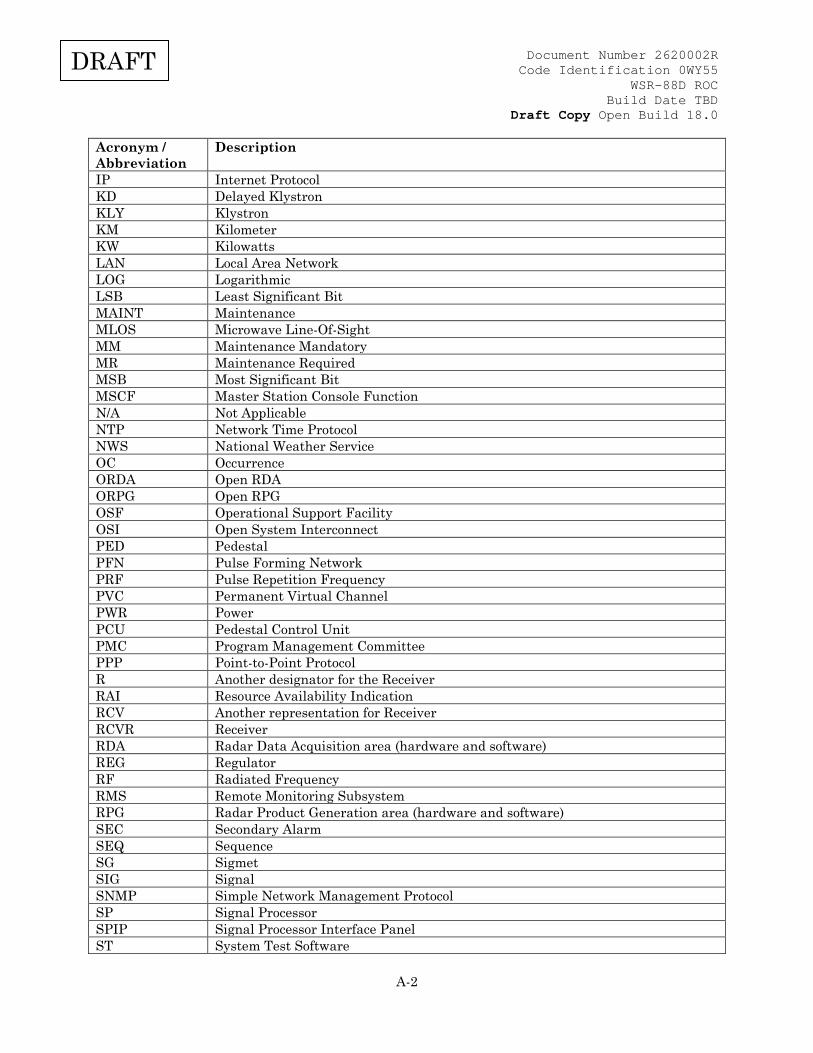
Document Number 2620002R Code Identification 0WY55
WSR-88D ROC Build Date TBD
Draft Copy Open Build 18.0
A-2
DRAFT
Acronym / Abbreviation
Description
IP Internet Protocol KD Delayed Klystron KLY Klystron KM Kilometer KW Kilowatts LAN Local Area Network LOG Logarithmic LSB Least Significant Bit MAINT Maintenance MLOS Microwave Line-Of-Sight MM Maintenance Mandatory MR Maintenance Required MSB Most Significant Bit MSCF Master Station Console Function N/A Not Applicable NTP Network Time Protocol NWS National Weather Service OC Occurrence ORDA Open RDA ORPG Open RPG OSF Operational Support Facility OSI Open System Interconnect PED Pedestal PFN Pulse Forming Network PRF Pulse Repetition Frequency PVC Permanent Virtual Channel PWR Power PCU Pedestal Control Unit PMC Program Management Committee PPP Point-to-Point Protocol R Another designator for the Receiver RAI Resource Availability Indication RCV Another representation for Receiver RCVR Receiver RDA Radar Data Acquisition area (hardware and software) REG Regulator RF Radiated Frequency RMS Remote Monitoring Subsystem RPG Radar Product Generation area (hardware and software) SEC Secondary Alarm SEQ Sequence SG Sigmet SIG Signal SNMP Simple Network Management Protocol SP Signal Processor SPIP Signal Processor Interface Panel ST System Test Software
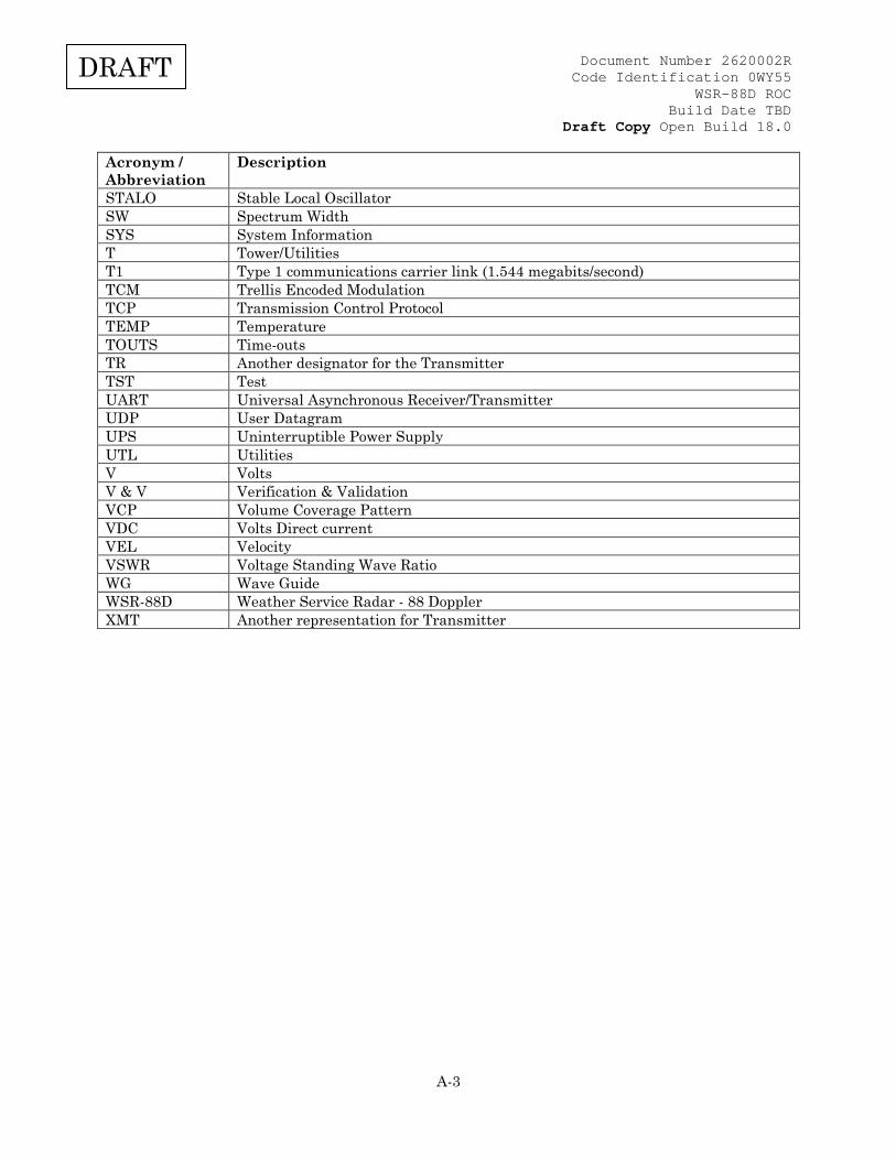
Document Number 2620002R Code Identification 0WY55
WSR-88D ROC Build Date TBD
Draft Copy Open Build 18.0
A-3
DRAFT
Acronym / Abbreviation
Description
STALO Stable Local Oscillator SW Spectrum Width SYS System Information T Tower/Utilities T1 Type 1 communications carrier link (1.544 megabits/second) TCM Trellis Encoded Modulation TCP Transmission Control Protocol TEMP Temperature TOUTS Time-outs TR Another designator for the Transmitter TST Test UART Universal Asynchronous Receiver/Transmitter UDP User Datagram UPS Uninterruptible Power Supply UTL Utilities V Volts V & V Verification & Validation VCP Volume Coverage Pattern VDC Volts Direct current VEL Velocity VSWR Voltage Standing Wave Ratio WG Wave Guide WSR-88D Weather Service Radar - 88 Doppler XMT Another representation for Transmitter

Document Number 2620002R Code Identification 0WY55
WSR-88D ROC Build Date TBD
Draft Copy Open Build 18.0
B-1
DRAFT
APPENDIX B UNIT DEFINITIONS AND SYMBOLOGY Unless otherwise noted, the units and symbology contained in this document adhere to those set forth in The International System of Units (SI). In some special cases there may be system limitations that force the use of non-standard symbology. In other special cases the quantity might not be recognized by the SI but is commonly used within the meteorological and radar engineering communities. References: 1) NIST Reference on Constants, Units, and Uncertainty (http://physics.nist.gov/cuu/index.html) Quantity Name Symbol Angular Velocity radian per second (2) rad/s degree per second (4) deg/s (5) Area square meter (2) m^2 (5) Computer Data byte (4) byte (5) octet (4) octet (5) halfword (4) halfword (5) Electrical Current ampere (1) A Electrical Potential Difference volt (2) V kilovolt kV millivolt mV Frequency hertz (2) Hz megahertz MHz Height kilometer km Length meter (1) m kilometer km nautical mile (3) nm (5) statute mile (4) mi (5) Mass kilogram (1) kg Percent percent (4) % (5) Plane Angle degree (3) deg (5) minute (3) min (5) radian (2) rad second (3) s (5) Power decibel dB (3) decibels above one milliwatt (4) dBm (5) kilowatt kW megawatt MW milliwatt mW watt (2) W Pressure bar (3) bar millibar (3) mb (5) Reflectivity decibels of equivalent
reflectivity dBZ
Speed knot(3) kt(5) meter per second (2) m/s mile per hour (4) mph (5) Thermodynamic Temperature degrees Celsius (2) deg C (5) K kelvin (1)

Document Number 2620002R Code Identification 0WY55
WSR-88D ROC Build Date TBD
Draft Copy Open Build 18.0
B-2
DRAFT
Quantity Name Symbol Time second (1) s microsecond usec (5) millisecond msec (5) nanosecond nsec (5) minute (3) min hour (3) h day (3) d month (4) mo (5) year (4) yr (5) Volume cubic meter (2) m^3 (5) Notes: 1. SI base unit 2. SI derived unit 3. Non-SI unit deemed acceptable for use by the SI 4. Unit not recognized by SI 5. Non-SI unit symbology
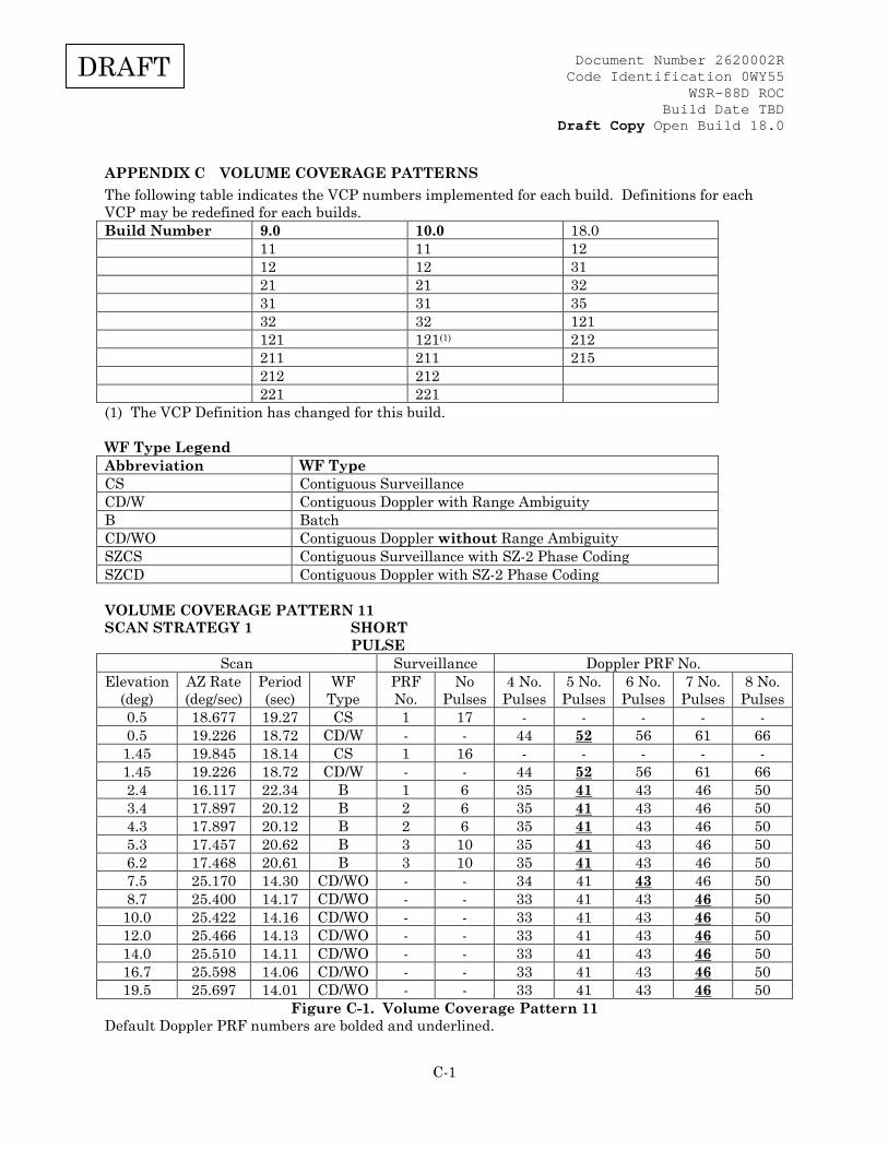
Document Number 2620002R Code Identification 0WY55
WSR-88D ROC Build Date TBD
Draft Copy Open Build 18.0
C-1
DRAFT
APPENDIX C VOLUME COVERAGE PATTERNS The following table indicates the VCP numbers implemented for each build. Definitions for each VCP may be redefined for each builds. Build Number 9.0 10.0 18.0 11 11 12 12 12 31 21 21 32 31 31 35 32 32 121 121 121(1) 212 211 211 215 212 212 221 221 (1) The VCP Definition has changed for this build. WF Type Legend Abbreviation WF Type CS Contiguous Surveillance CD/W Contiguous Doppler with Range Ambiguity B Batch CD/WO Contiguous Doppler without Range Ambiguity SZCS Contiguous Surveillance with SZ-2 Phase Coding SZCD Contiguous Doppler with SZ-2 Phase Coding VOLUME COVERAGE PATTERN 11 SCAN STRATEGY 1 SHORT
PULSE
Scan Surveillance Doppler PRF No. Elevation
(deg) AZ Rate (deg/sec)
Period (sec)
WF Type
PRF No.
No Pulses
4 No. Pulses
5 No. Pulses
6 No. Pulses
7 No. Pulses
8 No. Pulses
0.5 18.677 19.27 CS 1 17 - - - - - 0.5 19.226 18.72 CD/W - - 44 52 56 61 66 1.45 19.845 18.14 CS 1 16 - - - - - 1.45 19.226 18.72 CD/W - - 44 52 56 61 66 2.4 16.117 22.34 B 1 6 35 41 43 46 50 3.4 17.897 20.12 B 2 6 35 41 43 46 50 4.3 17.897 20.12 B 2 6 35 41 43 46 50 5.3 17.457 20.62 B 3 10 35 41 43 46 50 6.2 17.468 20.61 B 3 10 35 41 43 46 50 7.5 25.170 14.30 CD/WO - - 34 41 43 46 50 8.7 25.400 14.17 CD/WO - - 33 41 43 46 50 10.0 25.422 14.16 CD/WO - - 33 41 43 46 50 12.0 25.466 14.13 CD/WO - - 33 41 43 46 50 14.0 25.510 14.11 CD/WO - - 33 41 43 46 50 16.7 25.598 14.06 CD/WO - - 33 41 43 46 50 19.5 25.697 14.01 CD/WO - - 33 41 43 46 50
Figure C-1. Volume Coverage Pattern 11 Default Doppler PRF numbers are bolded and underlined.
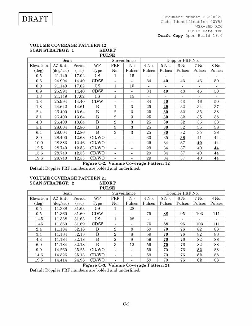
Document Number 2620002R Code Identification 0WY55
WSR-88D ROC Build Date TBD
Draft Copy Open Build 18.0
C-2
DRAFT
VOLUME COVERAGE PATTERN 12 SCAN STRATEGY: 1 SHORT
PULSE
Scan Surveillance Doppler PRF No. Elevation
(deg) AZ Rate (deg/sec)
Period (sec)
WF Type
PRF No.
No Pulses
4 No. Pulses
5 No. Pulses
6 No. Pulses
7 No. Pulses
8 No. Pulses
0.5 21.149 17.02 CS 1 15 - - - - - 0.5 24.994 14.40 CD/W - - 34 40 43 46 50 0.9 21.149 17.02 CS 1 15 - - - - - 0.9 25.994 14.40 CD/W - - 34 40 43 46 50 1.3 21.149 17.02 CS 1 15 - - - - - 1.3 25.994 14.40 CD/W - - 34 40 43 46 50 1.8 24.642 14.61 B 1 3 25 29 32 34 37 2.4 26.400 13.64 B 2 3 25 30 32 35 38 3.1 26.400 13.64 B 2 3 25 30 32 35 38 4.0 26.400 13.64 B 2 3 25 30 32 35 38 5.1 28.004 12.86 B 3 3 25 30 32 35 38 6.4 28.004 12.86 B 3 3 25 30 32 35 38 8.0 28.400 12.68 CD/WO - - 30 35 38 41 44 10.0 28.883 12.46 CD/WO - - 29 34 37 40 44 12.5 28.740 12.53 CD/WO - - 29 34 37 40 44 15.6 28.740 12.53 CD/WO - - 29 34 37 40 44 19.5 28.740 12.53 CD/WO - - 29 34 37 40 44
Figure C-2. Volume Coverage Pattern 12 Default Doppler PRF numbers are bolded and underlined. VOLUME COVERAGE PATTERN 21 SCAN STRATEGY: 2 SHORT
PULSE
Scan Surveillance Doppler PRF No. Elevation
(deg) AZ Rate (deg/sec)
Period (sec)
WF Type
PRF No.
No Pulses
4 No. Pulses
5 No. Pulses
6 No. Pulses
7 No. Pulses
8 No. Pulses
0.5 11.338 31.63 CS 1 28 - - - - - 0.5 11.360 31.69 CD/W - - 75 88 95 103 111 1.45 11.338 31.63 CS 1 28 - - - - - 1.45 11.360 31.69 CD/W - - 75 88 95 103 111 2.4 11.184 32.18 B 2 8 59 70 76 82 88 3.4 11.184 32.18 B 2 8 59 70 76 82 88 4.3 11.184 32.18 B 2 8 59 70 76 82 88 6.0 11.184 32.18 B 3 12 59 70 76 82 88 9.9 14.260 25.25 CD/WO - - 59 70 76 82 88 14.6 14.326 25.13 CD/WO - - 59 70 76 82 88 19.5 14.414 24.98 CD/WO - - 59 70 76 82 88
Figure C-3. Volume Coverage Pattern 21 Default Doppler PRF numbers are bolded and underlined.
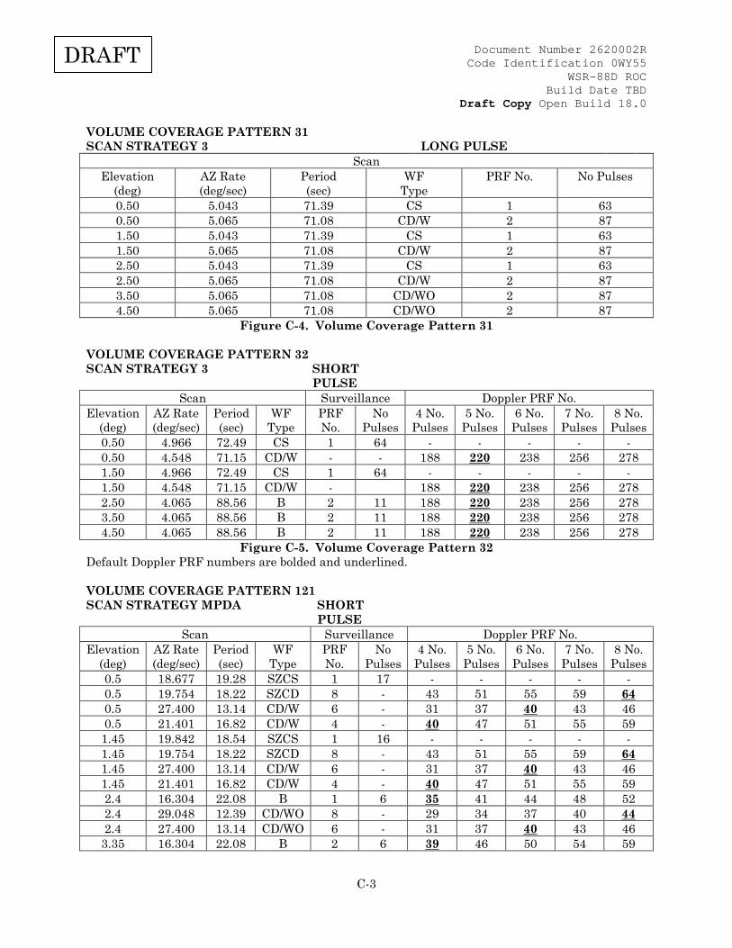
Document Number 2620002R Code Identification 0WY55
WSR-88D ROC Build Date TBD
Draft Copy Open Build 18.0
C-3
DRAFT
VOLUME COVERAGE PATTERN 31 SCAN STRATEGY 3 LONG PULSE
Scan Elevation
(deg) AZ Rate (deg/sec)
Period (sec)
WF Type
PRF No. No Pulses
0.50 5.043 71.39 CS 1 63 0.50 5.065 71.08 CD/W 2 87 1.50 5.043 71.39 CS 1 63 1.50 5.065 71.08 CD/W 2 87 2.50 5.043 71.39 CS 1 63 2.50 5.065 71.08 CD/W 2 87 3.50 5.065 71.08 CD/WO 2 87 4.50 5.065 71.08 CD/WO 2 87
Figure C-4. Volume Coverage Pattern 31 VOLUME COVERAGE PATTERN 32 SCAN STRATEGY 3 SHORT
PULSE
Scan Surveillance Doppler PRF No. Elevation
(deg) AZ Rate (deg/sec)
Period (sec)
WF Type
PRF No.
No Pulses
4 No. Pulses
5 No. Pulses
6 No. Pulses
7 No. Pulses
8 No. Pulses
0.50 4.966 72.49 CS 1 64 - - - - - 0.50 4.548 71.15 CD/W - - 188 220 238 256 278 1.50 4.966 72.49 CS 1 64 - - - - - 1.50 4.548 71.15 CD/W - 188 220 238 256 278 2.50 4.065 88.56 B 2 11 188 220 238 256 278 3.50 4.065 88.56 B 2 11 188 220 238 256 278 4.50 4.065 88.56 B 2 11 188 220 238 256 278
Figure C-5. Volume Coverage Pattern 32 Default Doppler PRF numbers are bolded and underlined. VOLUME COVERAGE PATTERN 121 SCAN STRATEGY MPDA SHORT
PULSE
Scan Surveillance Doppler PRF No. Elevation
(deg) AZ Rate (deg/sec)
Period (sec)
WF Type
PRF No.
No Pulses
4 No. Pulses
5 No. Pulses
6 No. Pulses
7 No. Pulses
8 No. Pulses
0.5 18.677 19.28 SZCS 1 17 - - - - - 0.5 19.754 18.22 SZCD 8 - 43 51 55 59 64 0.5 27.400 13.14 CD/W 6 - 31 37 40 43 46 0.5 21.401 16.82 CD/W 4 - 40 47 51 55 59 1.45 19.842 18.54 SZCS 1 16 - - - - - 1.45 19.754 18.22 SZCD 8 - 43 51 55 59 64 1.45 27.400 13.14 CD/W 6 - 31 37 40 43 46 1.45 21.401 16.82 CD/W 4 - 40 47 51 55 59 2.4 16.304 22.08 B 1 6 35 41 44 48 52 2.4 29.048 12.39 CD/WO 8 - 29 34 37 40 44 2.4 27.400 13.14 CD/WO 6 - 31 37 40 43 46 3.35 16.304 22.08 B 2 6 39 46 50 54 59
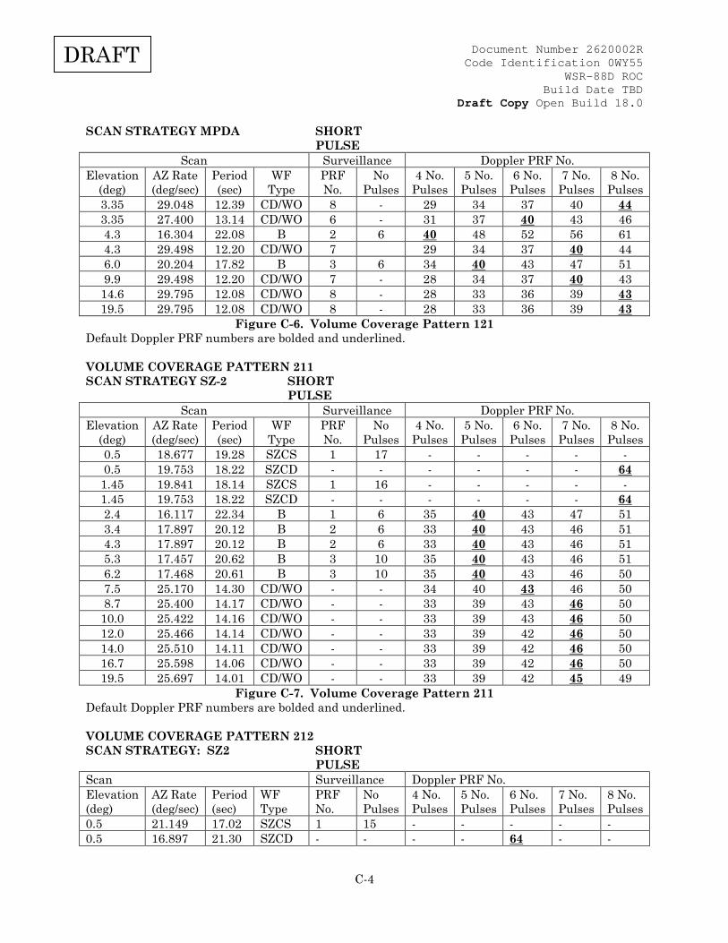
Document Number 2620002R Code Identification 0WY55
WSR-88D ROC Build Date TBD
Draft Copy Open Build 18.0
C-4
DRAFT
SCAN STRATEGY MPDA SHORT PULSE
Scan Surveillance Doppler PRF No. Elevation
(deg) AZ Rate (deg/sec)
Period (sec)
WF Type
PRF No.
No Pulses
4 No. Pulses
5 No. Pulses
6 No. Pulses
7 No. Pulses
8 No. Pulses
3.35 29.048 12.39 CD/WO 8 - 29 34 37 40 44 3.35 27.400 13.14 CD/WO 6 - 31 37 40 43 46 4.3 16.304 22.08 B 2 6 40 48 52 56 61 4.3 29.498 12.20 CD/WO 7 29 34 37 40 44 6.0 20.204 17.82 B 3 6 34 40 43 47 51 9.9 29.498 12.20 CD/WO 7 - 28 34 37 40 43 14.6 29.795 12.08 CD/WO 8 - 28 33 36 39 43 19.5 29.795 12.08 CD/WO 8 - 28 33 36 39 43
Figure C-6. Volume Coverage Pattern 121 Default Doppler PRF numbers are bolded and underlined. VOLUME COVERAGE PATTERN 211 SCAN STRATEGY SZ-2 SHORT
PULSE
Scan Surveillance Doppler PRF No. Elevation
(deg) AZ Rate (deg/sec)
Period (sec)
WF Type
PRF No.
No Pulses
4 No. Pulses
5 No. Pulses
6 No. Pulses
7 No. Pulses
8 No. Pulses
0.5 18.677 19.28 SZCS 1 17 - - - - - 0.5 19.753 18.22 SZCD - - - - - - 64 1.45 19.841 18.14 SZCS 1 16 - - - - - 1.45 19.753 18.22 SZCD - - - - - - 64 2.4 16.117 22.34 B 1 6 35 40 43 47 51 3.4 17.897 20.12 B 2 6 33 40 43 46 51 4.3 17.897 20.12 B 2 6 33 40 43 46 51 5.3 17.457 20.62 B 3 10 35 40 43 46 51 6.2 17.468 20.61 B 3 10 35 40 43 46 50 7.5 25.170 14.30 CD/WO - - 34 40 43 46 50 8.7 25.400 14.17 CD/WO - - 33 39 43 46 50 10.0 25.422 14.16 CD/WO - - 33 39 43 46 50 12.0 25.466 14.14 CD/WO - - 33 39 42 46 50 14.0 25.510 14.11 CD/WO - - 33 39 42 46 50 16.7 25.598 14.06 CD/WO - - 33 39 42 46 50 19.5 25.697 14.01 CD/WO - - 33 39 42 45 49
Figure C-7. Volume Coverage Pattern 211 Default Doppler PRF numbers are bolded and underlined. VOLUME COVERAGE PATTERN 212 SCAN STRATEGY: SZ2 SHORT
PULSE
Scan Surveillance Doppler PRF No. Elevation (deg)
AZ Rate (deg/sec)
Period (sec)
WF Type
PRF No.
No Pulses
4 No. Pulses
5 No. Pulses
6 No. Pulses
7 No. Pulses
8 No. Pulses
0.5 21.149 17.02 SZCS 1 15 - - - - - 0.5 16.897 21.30 SZCD - - - - 64 - -

Document Number 2620002R Code Identification 0WY55
WSR-88D ROC Build Date TBD
Draft Copy Open Build 18.0
C-5
DRAFT
SCAN STRATEGY: SZ2 SHORT PULSE
Scan Surveillance Doppler PRF No. Elevation (deg)
AZ Rate (deg/sec)
Period (sec)
WF Type
PRF No.
No Pulses
4 No. Pulses
5 No. Pulses
6 No. Pulses
7 No. Pulses
8 No. Pulses
0.9 21.149 17.02 SZCS 1 15 - - - - - 0.9 16.897 21.30 SZCD - - - - 64 - - 1.3 21.149 17.02 SZCS 1 15 - - - - - 1.3 16.897 21.30 SZCD - - - - 64 - - 1.8 24.642 14.61 B 1 3 23 28 30 32 35 2.4 26.400 13.64 B 2 3 24 28 31 33 36 3.1 26.400 13.64 B 2 3 24 28 31 33 36 4.0 26.400 13.64 B 2 3 24 28 31 33 36 5.1 28.004 12.86 B 3 3 24 29 31 34 37 6.4 28.004 12.86 B 3 3 24 29 31 34 37 8.0 28.400 12.68 CD/WO - - 30 35 38 41 44 10.0 28.883 12.46 CD/WO - - 29 35 38 41 44 12.5 28.740 12.53 CD/WO - - 29 35 38 41 44 15.6 28.740 12.53 CD/WO - - 29 35 38 41 44 19.5 28.740 12.53 CD/WO - - 29 35 38 41 44 Figure C-8 Volume Coverage Pattern 212 Default Doppler PRF numbers are bolded and underlined. VOLUME COVERAGE PATTERN 221 SCAN STRATEGY: SZ-2 SHORT
PULSE
Scan Surveillance Doppler PRF No. Elevation
(deg) AZ Rate (deg/sec)
Period (sec)
WF Type
PRF No.
No Pulses
4 No. Pulses
5 No. Pulses
6 No. Pulses
7 No. Pulses
8 No. Pulses
0.5 11.338 31.75 SZCS 1 28 - - - - - 0.5 15.612 23.06 SZCD - - 54 64 70 75 82 1.45 11.338 31.75 SZCS 1 28 - - - - - 1.45 15.612 23.06 SZCD - - 54 64 70 75 82 2.4 10.745 33.50 B 2 8 61 73 79 85 92 3.4 10.745 33.50 B 2 8 61 73 79 85 92 4.3 10.745 33.50 B 2 8 61 73 79 85 92 6.0 11.184 32.19 B 3 12 59 69 75 81 88 9.9 12.129 29.68 CD/WO - - 70 83 90 97 105 14.6 12.129 29.68 CD/WO - - 70 83 90 97 105 19.5 12.129 29.68 CD/WO - - 70 83 90 97 105
Figure C-9. Volume Coverage Pattern 221 Default Doppler PRF numbers are bolded and underlined.
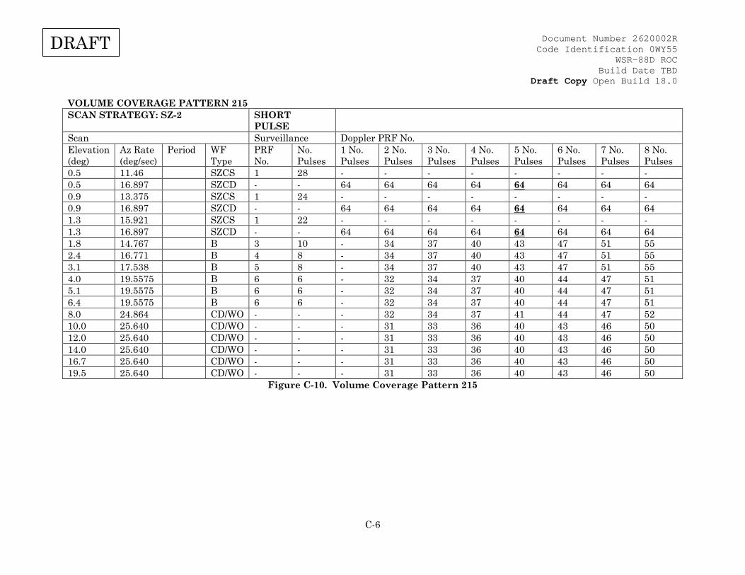
Document Number 2620002R Code Identification 0WY55
WSR-88D ROC Build Date TBD
Draft Copy Open Build 18.0
C-6
DRAFT
VOLUME COVERAGE PATTERN 215 SCAN STRATEGY: SZ-2 SHORT
PULSE
Scan Surveillance Doppler PRF No. Elevation (deg)
Az Rate (deg/sec)
Period WF Type
PRF No.
No. Pulses
1 No. Pulses
2 No. Pulses
3 No. Pulses
4 No. Pulses
5 No. Pulses
6 No. Pulses
7 No. Pulses
8 No. Pulses
0.5 11.46 SZCS 1 28 - - - - - - - - 0.5 16.897 SZCD - - 64 64 64 64 64 64 64 64 0.9 13.375 SZCS 1 24 - - - - - - - - 0.9 16.897 SZCD - - 64 64 64 64 64 64 64 64 1.3 15.921 SZCS 1 22 - - - - - - - - 1.3 16.897 SZCD - - 64 64 64 64 64 64 64 64 1.8 14.767 B 3 10 - 34 37 40 43 47 51 55 2.4 16.771 B 4 8 - 34 37 40 43 47 51 55 3.1 17.538 B 5 8 - 34 37 40 43 47 51 55 4.0 19.5575 B 6 6 - 32 34 37 40 44 47 51 5.1 19.5575 B 6 6 - 32 34 37 40 44 47 51 6.4 19.5575 B 6 6 - 32 34 37 40 44 47 51 8.0 24.864 CD/WO - - - 32 34 37 41 44 47 52 10.0 25.640 CD/WO - - - 31 33 36 40 43 46 50 12.0 25.640 CD/WO - - - 31 33 36 40 43 46 50 14.0 25.640 CD/WO - - - 31 33 36 40 43 46 50 16.7 25.640 CD/WO - - - 31 33 36 40 43 46 50 19.5 25.640 CD/WO - - - 31 33 36 40 43 46 50
Figure C-10. Volume Coverage Pattern 215

Document Number 2620002R Code Identification 0WY55
WSR-88D ROC Build Date TBD
Draft Copy Open Build 18.0
C-7
DRAFT
VOLUME COVERAGE PATTERN 35 SCAN STRATEGY: SZ-2 SHORT
PULSE
Scan Surveillance Doppler PRF No. Elevation
(deg) Az Rate (deg/sec)
Period WF Type
PRF No.
No. Pulses
1 No. Pulses
2 No. Pulses
3 No. Pulses
4 No. Pulses
5 No. Pulses
6 No. Pulses
7 No. Pulses
8 No. Pulses
0.5 4.966 SZCS 1 64 - - - - - - - - 0.5 15.612 SZCD - - 64 64 64 64 64 64 64 64 0.9 4.966 SZCS 1 64 - - - - - - - - 0.9 15.612 SZCD - - 64 64 64 64 64 64 64 64 1.3 5.473 SZCS 2 64 - - - - - - - - 1.3 15.612 SZCD - - 64 64 64 64 64 64 64 64 1.8 15.134 B 3 6 - 38 41 44 48 52 56 61 2.4 15.863 B 4 6 - 38 41 44 48 52 56 61 3.1 16.391 B 5 6 - 38 41 44 48 52 56 61 4.0 17.542 B 6 6 - 36 39 42 46 50 54 58 5.1 17.542 B 6 6 - 36 39 42 46 50 54 58 6.4 17.542 B 6 6 - 36 39 42 46 50 54 58
Figure C-11. Volume Coverage Pattern 35